WO2016002862A1 - ラベル付きブロー成形容器及びブロー成形用金型 - Google Patents
ラベル付きブロー成形容器及びブロー成形用金型 Download PDFInfo
- Publication number
- WO2016002862A1 WO2016002862A1 PCT/JP2015/069075 JP2015069075W WO2016002862A1 WO 2016002862 A1 WO2016002862 A1 WO 2016002862A1 JP 2015069075 W JP2015069075 W JP 2015069075W WO 2016002862 A1 WO2016002862 A1 WO 2016002862A1
- Authority
- WO
- WIPO (PCT)
- Prior art keywords
- label
- molded container
- blow
- blow molded
- mold
- Prior art date
- Legal status (The legal status is an assumption and is not a legal conclusion. Google has not performed a legal analysis and makes no representation as to the accuracy of the status listed.)
- Ceased
Links
Images


Classifications
-
- B—PERFORMING OPERATIONS; TRANSPORTING
- B65—CONVEYING; PACKING; STORING; HANDLING THIN OR FILAMENTARY MATERIAL
- B65D—CONTAINERS FOR STORAGE OR TRANSPORT OF ARTICLES OR MATERIALS, e.g. BAGS, BARRELS, BOTTLES, BOXES, CANS, CARTONS, CRATES, DRUMS, JARS, TANKS, HOPPERS, FORWARDING CONTAINERS; ACCESSORIES, CLOSURES, OR FITTINGS THEREFOR; PACKAGING ELEMENTS; PACKAGES
- B65D1/00—Rigid or semi-rigid containers having bodies formed in one piece, e.g. by casting metallic material, by moulding plastics, by blowing vitreous material, by throwing ceramic material, by moulding pulped fibrous material or by deep-drawing operations performed on sheet material
- B65D1/02—Bottles or similar containers with necks or like restricted apertures, designed for pouring contents
-
- B—PERFORMING OPERATIONS; TRANSPORTING
- B65—CONVEYING; PACKING; STORING; HANDLING THIN OR FILAMENTARY MATERIAL
- B65D—CONTAINERS FOR STORAGE OR TRANSPORT OF ARTICLES OR MATERIALS, e.g. BAGS, BARRELS, BOTTLES, BOXES, CANS, CARTONS, CRATES, DRUMS, JARS, TANKS, HOPPERS, FORWARDING CONTAINERS; ACCESSORIES, CLOSURES, OR FITTINGS THEREFOR; PACKAGING ELEMENTS; PACKAGES
- B65D25/00—Details of other kinds or types of rigid or semi-rigid containers
- B65D25/20—External fittings
- B65D25/205—Means for the attachment of labels, cards, coupons or the like
-
- B—PERFORMING OPERATIONS; TRANSPORTING
- B29—WORKING OF PLASTICS; WORKING OF SUBSTANCES IN A PLASTIC STATE IN GENERAL
- B29C—SHAPING OR JOINING OF PLASTICS; SHAPING OF MATERIAL IN A PLASTIC STATE, NOT OTHERWISE PROVIDED FOR; AFTER-TREATMENT OF THE SHAPED PRODUCTS, e.g. REPAIRING
- B29C45/00—Injection moulding, i.e. forcing the required volume of moulding material through a nozzle into a closed mould; Apparatus therefor
- B29C45/17—Component parts, details or accessories; Auxiliary operations
- B29C45/20—Injection nozzles
- B29C45/24—Cleaning equipment
-
- B—PERFORMING OPERATIONS; TRANSPORTING
- B29—WORKING OF PLASTICS; WORKING OF SUBSTANCES IN A PLASTIC STATE IN GENERAL
- B29C—SHAPING OR JOINING OF PLASTICS; SHAPING OF MATERIAL IN A PLASTIC STATE, NOT OTHERWISE PROVIDED FOR; AFTER-TREATMENT OF THE SHAPED PRODUCTS, e.g. REPAIRING
- B29C49/00—Blow-moulding, i.e. blowing a preform or parison to a desired shape within a mould; Apparatus therefor
- B29C49/24—Lining or labelling
- B29C49/2408—In-mould lining or labelling
-
- B—PERFORMING OPERATIONS; TRANSPORTING
- B29—WORKING OF PLASTICS; WORKING OF SUBSTANCES IN A PLASTIC STATE IN GENERAL
- B29C—SHAPING OR JOINING OF PLASTICS; SHAPING OF MATERIAL IN A PLASTIC STATE, NOT OTHERWISE PROVIDED FOR; AFTER-TREATMENT OF THE SHAPED PRODUCTS, e.g. REPAIRING
- B29C49/00—Blow-moulding, i.e. blowing a preform or parison to a desired shape within a mould; Apparatus therefor
- B29C49/42—Component parts, details or accessories; Auxiliary operations
- B29C49/48—Moulds
-
- B—PERFORMING OPERATIONS; TRANSPORTING
- B29—WORKING OF PLASTICS; WORKING OF SUBSTANCES IN A PLASTIC STATE IN GENERAL
- B29C—SHAPING OR JOINING OF PLASTICS; SHAPING OF MATERIAL IN A PLASTIC STATE, NOT OTHERWISE PROVIDED FOR; AFTER-TREATMENT OF THE SHAPED PRODUCTS, e.g. REPAIRING
- B29C65/00—Joining or sealing of preformed parts, e.g. welding of plastics materials; Apparatus therefor
- B29C65/02—Joining or sealing of preformed parts, e.g. welding of plastics materials; Apparatus therefor by heating, with or without pressure
-
- B—PERFORMING OPERATIONS; TRANSPORTING
- B65—CONVEYING; PACKING; STORING; HANDLING THIN OR FILAMENTARY MATERIAL
- B65D—CONTAINERS FOR STORAGE OR TRANSPORT OF ARTICLES OR MATERIALS, e.g. BAGS, BARRELS, BOTTLES, BOXES, CANS, CARTONS, CRATES, DRUMS, JARS, TANKS, HOPPERS, FORWARDING CONTAINERS; ACCESSORIES, CLOSURES, OR FITTINGS THEREFOR; PACKAGING ELEMENTS; PACKAGES
- B65D23/00—Details of bottles or jars not otherwise provided for
- B65D23/08—Coverings or external coatings
- B65D23/0842—Sheets or tubes applied around the bottle with or without subsequent folding operations
- B65D23/0864—Applied in mould
-
- G—PHYSICS
- G09—EDUCATION; CRYPTOGRAPHY; DISPLAY; ADVERTISING; SEALS
- G09F—DISPLAYING; ADVERTISING; SIGNS; LABELS OR NAME-PLATES; SEALS
- G09F3/00—Labels, tag tickets, or similar identification or indication means; Seals; Postage or like stamps
- G09F3/02—Forms or constructions
-
- B—PERFORMING OPERATIONS; TRANSPORTING
- B29—WORKING OF PLASTICS; WORKING OF SUBSTANCES IN A PLASTIC STATE IN GENERAL
- B29C—SHAPING OR JOINING OF PLASTICS; SHAPING OF MATERIAL IN A PLASTIC STATE, NOT OTHERWISE PROVIDED FOR; AFTER-TREATMENT OF THE SHAPED PRODUCTS, e.g. REPAIRING
- B29C49/00—Blow-moulding, i.e. blowing a preform or parison to a desired shape within a mould; Apparatus therefor
- B29C49/24—Lining or labelling
- B29C2049/2412—Lining or labelling outside the article
-
- B—PERFORMING OPERATIONS; TRANSPORTING
- B29—WORKING OF PLASTICS; WORKING OF SUBSTANCES IN A PLASTIC STATE IN GENERAL
- B29C—SHAPING OR JOINING OF PLASTICS; SHAPING OF MATERIAL IN A PLASTIC STATE, NOT OTHERWISE PROVIDED FOR; AFTER-TREATMENT OF THE SHAPED PRODUCTS, e.g. REPAIRING
- B29C49/00—Blow-moulding, i.e. blowing a preform or parison to a desired shape within a mould; Apparatus therefor
- B29C49/24—Lining or labelling
- B29C2049/2414—Linings or labels, e.g. specific geometry, multi-layered or material
- B29C2049/24302—Label materials
-
- B—PERFORMING OPERATIONS; TRANSPORTING
- B29—WORKING OF PLASTICS; WORKING OF SUBSTANCES IN A PLASTIC STATE IN GENERAL
- B29C—SHAPING OR JOINING OF PLASTICS; SHAPING OF MATERIAL IN A PLASTIC STATE, NOT OTHERWISE PROVIDED FOR; AFTER-TREATMENT OF THE SHAPED PRODUCTS, e.g. REPAIRING
- B29C49/00—Blow-moulding, i.e. blowing a preform or parison to a desired shape within a mould; Apparatus therefor
- B29C49/24—Lining or labelling
- B29C2049/2464—Means for verifying or keeping the position of the lining or label, e.g. sensors, or attachment on mould wall
- B29C2049/2472—Means for verifying or keeping the position of the lining or label, e.g. sensors, or attachment on mould wall using vacuum
-
- B—PERFORMING OPERATIONS; TRANSPORTING
- B29—WORKING OF PLASTICS; WORKING OF SUBSTANCES IN A PLASTIC STATE IN GENERAL
- B29L—INDEXING SCHEME ASSOCIATED WITH SUBCLASS B29C, RELATING TO PARTICULAR ARTICLES
- B29L2031/00—Other particular articles
- B29L2031/712—Containers; Packaging elements or accessories, Packages
-
- B—PERFORMING OPERATIONS; TRANSPORTING
- B29—WORKING OF PLASTICS; WORKING OF SUBSTANCES IN A PLASTIC STATE IN GENERAL
- B29L—INDEXING SCHEME ASSOCIATED WITH SUBCLASS B29C, RELATING TO PARTICULAR ARTICLES
- B29L2031/00—Other particular articles
- B29L2031/712—Containers; Packaging elements or accessories, Packages
- B29L2031/7158—Bottles
-
- B—PERFORMING OPERATIONS; TRANSPORTING
- B65—CONVEYING; PACKING; STORING; HANDLING THIN OR FILAMENTARY MATERIAL
- B65D—CONTAINERS FOR STORAGE OR TRANSPORT OF ARTICLES OR MATERIALS, e.g. BAGS, BARRELS, BOTTLES, BOXES, CANS, CARTONS, CRATES, DRUMS, JARS, TANKS, HOPPERS, FORWARDING CONTAINERS; ACCESSORIES, CLOSURES, OR FITTINGS THEREFOR; PACKAGING ELEMENTS; PACKAGES
- B65D2203/00—Decoration means, markings, information elements, contents indicators
- B65D2203/02—Labels
-
- G—PHYSICS
- G09—EDUCATION; CRYPTOGRAPHY; DISPLAY; ADVERTISING; SEALS
- G09F—DISPLAYING; ADVERTISING; SIGNS; LABELS OR NAME-PLATES; SEALS
- G09F3/00—Labels, tag tickets, or similar identification or indication means; Seals; Postage or like stamps
- G09F3/02—Forms or constructions
- G09F2003/0272—Labels for containers
Definitions
- the present invention relates to a blow molded container having a label with a three-dimensional shape and a mold suitable for producing the blow molded container.
- Patent Document 1 Japanese Unexamined Patent Application Publication No. 2012-180096 (Patent Document 1) and Japanese Unexamined Patent Application Publication No. 2011-246194 (Patent Document 2) prevent deformation of a blow molded container with a label, From the viewpoint of imparting a three-dimensional shape to a labeled blow-molded container, it has been proposed.
- Patent Document 3 discloses a cylindrical hollow container having a knurled protrusion (see FIGS. 8 and 25a).
- the present invention solves the technical problem and provides a blow molded container with a label and a mold for blow molding having one or both of a convex portion and a concave portion on the label surface.
- a blow-molded container with a label formed by heat-sealing a blow-molded container containing a thermoplastic resin and a label containing a thermoplastic resin film, wherein the label is attached
- a level h indicating a distance between the highest part of the label surface and the lowest part of the label surface, having one or both of a convex part and a concave part on the attached label surface, with the label surface as a reference in the height direction.
- a blow molded container with a label of 0.3 mm or more is provided.
- the maximum inclination angle theta 1 which the tangent of the side surface of the convex portion and the label side forms is 170 ° or less 85 ° or more.
- the maximum inclination angle theta 2 which the tangent to the label surface of the side of the recess forms is 275 ° or less 190 ° or more.
- the thickness of the label is 20 to 200 ⁇ m as measured by A method of JIS K 7130: 1999.
- the thermoplastic resin film is an unstretched film.
- the label thermoplastic resin film is a biaxially stretched film.
- at least one layer in which the label is formed from at least one resin selected from the group consisting of a polyolefin resin and a polyester resin.
- a blow molded container with a label in any one of the first to seventh aspects, is a group consisting of a polyolefin resin, a polyester resin, a polycarbonate resin, and a polystyrene resin. It is a blow molded container with a label which is 1 or more selected from.
- the label has print information.
- the printing information is formed by oil-based ink or radiation curable ink.
- the print information is formed with an ink amount of 0.5 to 6 g / m 2 in terms of solid printing.
- a blow molding mold having a cavity, wherein the mold has one or both of a convex part and a concave part at a portion in contact with a label on the inner wall surface of the mold,
- a blow molding die in which a step H indicating a distance between the highest portion of the inner wall surface and the lowest portion of the inner wall surface is 0.3 mm or more with the vertical direction of the inner wall surface as a reference in the height direction.
- the blow-molding mold is a blow-molded container with a label obtained by thermally fusing a blow-molded container containing a thermoplastic resin and a label containing a thermoplastic resin film. Is used to form
- the present invention can prevent the label from floating from the container or the label from tearing.
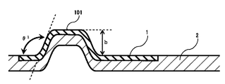
- FIG. 1 is a cross-sectional view of a label surface in a blow molded container with a label having a convex portion on the label surface.
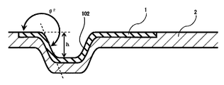
- FIG. 2 is a cross-sectional view of the label surface of the blow molded container with a label having a concave portion on the label surface.
- FIG. 3 is a cross-sectional view of a label surface in a blow molded container with a label having a convex portion and a concave portion on the label surface.
- FIG. 4 is a cross-sectional view of a blow molding die.
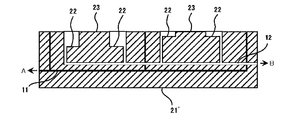
- FIG. 5 is a sectional view of the inner wall surface of the mold used in the example.
- the blow-molded container with a label of the present invention is formed by thermally fusing a blow-molded container 2 containing a thermoplastic resin and a label 1 containing a thermoplastic resin film.
- the blow-molded container has one or both of a convex portion 101 and a concave portion 102 at a location where the label 1 is affixed (hereinafter referred to as “label surface”).
- label surface a convex portion 101 and a concave portion 102 at a location where the label 1 is affixed
- the level difference h indicating the distance between the highest part on the surface of the label 1 and the lowest part on the surface of the label 1 is 0.3 mm or more with the label surface as a reference in the height direction.
- the blow molded container 2 contains a thermoplastic resin.
- a thermoplastic resin a material capable of forming a hollow container is used.
- a thermoplastic resin is used, and examples thereof include polyethylene terephthalate (PET) and copolymers thereof, polyolefin resins such as polypropylene (PP) and polyethylene (PE), and polycarbonate resins.
- PET polyethylene terephthalate
- PP polypropylene
- PE polyethylene
- polycarbonate resins polycarbonate resins
- the thermoplastic resin composition which has these thermoplastic resins as a main component and to which various additives are added.
- the label 1 includes a thermoplastic resin film.
- the thermoplastic resin film can be of any material and configuration. Or a manufacturing method.
- the thermoplastic resin film may have a single layer structure or a multilayer structure having two or more layers.
- thermoplastic resin included in the thermoplastic resin film examples include polyolefin resins such as polyethylene and polypropylene; polystyrene resins; polyester resins such as polyethylene terephthalate (PET) and polylactic acid; polyamide resins such as nylon-6; Polycarbonate resin is mentioned.
- these resins one kind or a mixture of two or more kinds can be used.
- thermoplastic resins it is preferable to use a polyolefin resin or a polyester resin, and from the viewpoint of excellent film processability, it is preferable to use a polyolefin resin.
- the thermoplastic resin film preferably includes at least one layer formed of at least one resin selected from the group consisting of polyolefin resins and polyester resins, and includes at least one layer formed of polyolefin resin films. It is more preferable.
- a laminate of different materials such as a biaxially stretched PET / non-stretched polypropylene (CPP) film and a biaxially stretched PET / biaxially stretched polypropylene (BOPP) film can be used.
- CPP biaxially stretched PET / non-stretched polypropylene
- BOPP biaxially stretched PET / biaxially stretched polypropylene
- the thermoplastic resin film preferably contains an inorganic fine powder in addition to the thermoplastic resin.
- the label 1 can be whitened and made opaque, and the visibility of printing provided on the label 1 can be improved.
- the kind of the inorganic fine powder calcium carbonate, talc, and titanium oxide are preferable from the viewpoints of whitening, opacification, and resin moldability.
- the surface of these inorganic fine powders may be subjected to a hydrophilic treatment or a hydrophobic treatment in advance.
- the particle diameter of the inorganic fine powder is represented by a volume average particle diameter measured by a laser diffraction method, and the volume average particle diameter is usually 0.01 ⁇ m or more, preferably from the viewpoint of achieving whitening and opacification of the label 1 Is 0.1 ⁇ m or more. On the other hand, from the viewpoint of improving the appearance of the label 1, it is usually 15 ⁇ m or less, preferably 5 ⁇ m or less.
- the label 1 preferably contains 1% by mass or more of inorganic fine powder, more preferably 5% by mass or more.
- the label 1 preferably contains 25% by mass or less of inorganic fine powder, and more preferably contains 20% by mass or less.
- the adhesive layer has a function of sticking to the blow molded container 2 in the label 1.
- the adhesive layer is usually composed of a resin composition mainly composed of a thermoplastic resin having a melting point lower than that of the thermoplastic resin constituting the label 1.
- thermoplastic resin used in the adhesive layer examples include ultra-low density, low density, or medium density high pressure polyethylene, linear linear low density polyethylene, ethylene / vinyl acetate copolymer, maleic acid modified ethylene / acetic acid.
- the adhesive layer When the adhesive layer is provided on the label 1, it may be provided by coextrusion when the thermoplastic resin film is produced, or may be provided by extrusion lamination in the course of producing the thermoplastic resin film, and the heat that becomes the adhesive layer.
- the plastic resin composition After the plastic resin composition is formed into a film, it may be provided by being attached to a thermoplastic resin film as a base material.
- the thermoplastic resin used in the adhesive layer may be dissolved in an organic solvent and then coated with a comma coater or gravure coater and dried, or the thermoplastic resin used in the adhesive layer may be converted into an aqueous emulsion.
- the aqueous paint containing may be applied by a gravure coater and dried.
- the surface of the adhesive layer of the label 1 is preferably embossed so that the air between the label 1 and the blow-molded container 2 is quickly discharged and no air pocket (blister) is formed.
- the thermoplastic resin film contained in the label 1 may be an unstretched layer, a uniaxially stretched layer, or a biaxially stretched layer.
- an unstretched layer is preferable from the viewpoint of improving the shapeability of the projections or recesses provided on the label surface of the blow-molded container.
- the thermoplastic resin film is an unstretched layer, from the viewpoint of increasing whiteness, the thermoplastic resin film preferably contains 0.5 to 10% by mass of titanium oxide, and preferably contains 1 to 5% by mass. More preferred.
- thermoplastic resin film When the thermoplastic resin film is a uniaxially stretched layer, it is preferable to give direction to the design.
- thermoplastic resin film When the thermoplastic resin film is a biaxially stretched layer, it is important not to make the stretch ratio too high in order to leave a stretchable force from the viewpoint of improving the shapeability of the projections or recesses provided on the label surface.
- the magnification (longitudinal draw ratio ⁇ lateral draw ratio) is preferably 50 times or less, and more preferably 40 times or less.
- the stretch ratio of the thermoplastic resin film is preferably 4 times or more, and more preferably 9 times or more.
- the thermoplastic resin film when it is necessary to increase the whiteness of the thermoplastic resin film, is preferably a stretched film containing 15% by mass or more, preferably 20% by mass or more of inorganic fine powder.
- Label 1 can be given print information. In general, printing is performed on one side of the label 1 and an adhesive layer is provided on the other side of the label 1.
- a recording layer suitable for printing can be provided on the surface of the label 1 and the print information can be provided via the recording layer.
- silk printing, gravure printing, offset printing, flexographic printing, various ink jet printing, digital printing, and the like are performed.
- silk printing and UV ink jet systems that can thicken the ink are preferable because the ink layer is easily cracked by stretching stress during molding, and can withstand the stress.
- oil-based ink or radiation curable ink is preferable.
- radiation-curable ink it is preferable to use visible light, ultraviolet light, or electron beam as radiation.
- the ink after curing is too hard, the ink layer is subject to stretching stress at the time of molding and is easily cracked.
- the printing information is preferably formed with an ink amount of 0.5 to 6 g / m 2 in terms of solid printing.
- the amount of ink is more preferably 1 g / m 2 or more, and further preferably 1.5 g / m 2 . Moreover, 5.5 g / m 2 or less is more preferable, and 5 g / m 2 or less is more preferable.
- the surface of the label 1 can be decorated.
- Examples of the decorating method include bonding of vapor deposition films, foil pressing, holograms, and the like.
- the recording layer can be provided by coating after applying an oxidation treatment to the surface of the thermoplastic resin film.
- Examples of the surface oxidation treatment include corona discharge treatment, flame treatment, plasma treatment, glow discharge treatment, and ozone treatment.
- a method for providing the recording layer there is a method in which a surface treatment liquid containing at least an antistatic agent and a polymer binder is applied and dried if necessary.
- the thickness of the label 1 thus obtained is preferably 20 ⁇ m or more, more preferably 30 ⁇ m or more, and further preferably 45 ⁇ m or more from the viewpoint of stable film formation.
- the thickness of the label 1 is preferably 200 ⁇ m or less, more preferably 180 ⁇ m or less, and further preferably 160 ⁇ m or less from the viewpoint of following the shape of the mold.
- the thickness of the label 1 is obtained by measuring with a constant pressure thickness measuring instrument based on the A method of JIS K 7130: 1999 “Plastics-Film and Sheet—Thickness Measuring Method”.
- the porosity of the label 1 is preferably 2% or more, and more preferably 10% or more.
- the label 1 may become transparent at the time of molding the blow molded container with a label, or the formation of convex portions or concave portions on the label surface may be reduced.
- the rate is preferably 60% or less, and more preferably 50% or less.
- the porosity of the label 1 is calculated by the following formula using the density ⁇ of the label 1 and the true density ⁇ 0 of the resin composition used for forming the label 1.
- Porosity (%) ( ⁇ 0 ⁇ ) / ⁇ 0 ⁇ 0 : True density of the thermoplastic resin composition
- ⁇ Label density
- the true density ⁇ 0 is based on the A method of JIS K 7112: 1999 “Plastics—Method of measuring density and specific gravity of non-foamed plastic” It calculates
- the density ⁇ of the label 1 is obtained by dividing the basis weight of the label 1 by the thickness of the label 1.
- the basis weight of the label 1 is based on JIS P 8124: 2011 “Paper and paperboard—Measurement method of basis weight”, and a sample punched out to a size of 100 mm ⁇ 100 mm is weighed with an electronic balance. Divide and seek.
- the blow molded container with a label is formed by thermally fusing the blow molded container 2 and the label 1 together. Furthermore, the blow molded container with a label has one or both of a convex part and a concave part on the label surface to which the label 1 is attached.
- the step h indicating the distance between the highest part of the surface of the label 1 and the lowest part of the surface of the label 1 with the label surface as a reference in the height direction is 0.3 mm or more.
- the level difference h is preferably 0.5 mm or more, and more preferably 1 mm or more.
- the upper limit of the level difference h is not particularly limited, it is preferably 20 mm or less, and more preferably 10 mm or less, from the viewpoint of shape followability of the decorative layer such as printing or foil.
- the blow molded container with a label has one or both of a convex portion and a concave portion on the label surface.
- the maximum inclination angle ⁇ 1 formed by the tangent to the side surface of the convex portion provided on the label surface and the label surface is greater than 0 ° and less than 180 °.
- the maximum inclination angle ⁇ 2 formed by the tangent to the side surface of the concave portion provided on the label surface and the label surface is greater than 180 ° and less than 360 °.
- the maximum inclination angle ⁇ 1 is preferably 85 ° or more, more preferably 90 ° or more, and further preferably 95 ° or more. Further, the maximum inclination angle ⁇ 1 is preferably 170 ° or less, more preferably 160 ° or less, and further preferably 150 ° or less. When the maximum inclination angle theta 1 is in the range, to be more easily removed from the mold after molding of labeled blow-molded container and, at the same time, three-dimensional feeling of the resulting labeled blow molded containers can be emphasized.
- the maximum inclination angle theta 2 is preferably at least 190 °, more preferably 200 ° or more, more preferably at least 210 °.
- the maximum inclination angle ⁇ 2 is preferably 275 ° or less, more preferably 270 ° or less, and further preferably 265 ° or less.
- the maximum inclination angle is obtained by cutting the cross section so as to cross the convex portion or concave portion provided on the label surface and observing the cross section with an optical microscope and analyzing the observation image, or by detecting the convex portion provided on the label surface.
- the part or the recess is directly determined by a laser displacement meter.
- the maximum inclination angle ⁇ 1 when one blow-molded container with a label can take a plurality of inclination angles of the convex portion, the one with the inclination angle closest to 90 ° is set as the maximum inclination angle ⁇ 1 .
- the one blow molded container with a label can take a plurality of inclination angles of the recesses, the one with the inclination angle closest to 270 ° is set as the maximum inclination angle ⁇ 2 .
- the present invention provides a cavity suitable for forming a blow molded container with a label obtained by thermally fusing the blow molded container 2 containing the thermoplastic resin and the label 1 containing the thermoplastic resin film as described above.
- a blow molding mold is provided.
- the blow molding die 21 of the present invention has one or both of a convex portion 23 and a concave portion 22 at a portion in contact with the label on the inner wall surface, and the concave portion 22 on the inner wall surface of the mold.
- the convex portion 23 on the inner wall surface of the mold corresponds to the concave portion 102 of the blow molded container.
- the step H indicating the distance between the highest part of the inner wall surface and the lowest part of the inner wall surface is 0.3 mm or more with the vertical direction of the inner wall surface of the blow molding die as the reference in the height direction.
- One or both of the concave portion 22 and the convex portion 23 are provided.
- the mold is preferably provided with a suction port 11 for holding the label at the label contact portion on the wall surface, as in normal in-mold molding, and sucks air existing between the label and the mold ( Arrow A).
- the suction port 11 has a diameter of 0.3 mm or more from the viewpoint of sure suction.
- the suction port 11 is 0.6 mm or less from a viewpoint of making the trace of the suction port 11 difficult to remain on the label surface.
- the exhaust port 12 preferably has a diameter of 0.3 to 0.8 mm.
- a label including a thermoplastic resin film is molded through a process such as punching to form an in-mold label, which is inserted into a mold of a blow molding machine, Install in a predetermined place in the mold.
- a process such as punching to form an in-mold label
- the punched labels are bundled and set in a label magazine, and a robot (automatic label feeder) having a suction cup is used.
- robot automated label feeder
- in-mold labels are individually taken out from the label magazine, inserted into a mold, and installed at a predetermined location in the mold.
- Such robots are made by Guangzhou Xinqi Electric Technology Co., Ltd., Beijing Jinglong Great Technology Co., Ltd., Zhangjiagang Doxing Machinery Co., Ltd., Tianqi Automation Machinery Manufacturing Co., Ltd., Tahara Co., Star Seiki Co., Ltd. Manufactured by Seylor, Yushin, Pentel, etc. can be used.
- the in-mold labels may be manually taken out one by one and installed at a predetermined location in the mold.
- ⁇ In-mold labels installed in the mold are fixed to the inner wall of the mold using a well-known technique such as suction or static electricity so that the position does not shift or drop.
- a well-known technique such as suction or static electricity
- the label can be sucked from a suction port provided in the mold and fixed to the inner wall of the mold.
- the in-mold label may be charged by a charging device such as a charge bar or pinner connected to the DC high voltage generator, and the label may be fixed to the inner wall of the mold by static electricity. it can.
- the blow molding method includes a direct blow method in which the required amount of hot parison is extruded and then the mold is closed and blown.
- the preform is molded by injection molding in advance, and is slightly lower than the glass transition temperature of the thermoplastic resin.
- Stretch blow method that mechanically stretches in the extrusion direction of the preform at a temperature, preforms the preform by injection molding in advance, and the resulting preform is either cooled or moved to a blow mold without cooling
- An injection blow method in which the mold is closed and blown can be applied.
- Suitable examples of the resin material used for forming the blow molded container are as described above, and examples thereof include polyolefin resin, polyester resin, polycarbonate resin, and polystyrene resin.
- the resin material is handled in a desired temperature range at the time of blow molding, and the parison formed by melt-extrusion of the resin material is preferably 150 ° C. or higher as the parison temperature immediately after being extruded from the die. .
- the temperature is more preferably in the range of 150 to 250 ° C, and still more preferably in the range of 150 to 220 ° C. If the parison temperature is 150 ° C. or higher, the heat seal layer on the in-mold label can be sufficiently activated to heat-seal the label.
- the parison temperature immediately after extrusion can be measured directly with a thermocouple thermometer or the like, or indirectly measured with an infrared thermometer or the like.
- parison controller When forming a parison, it is preferable to change the thickness of the formed parison according to the shape of the blow molded container with a label to be finally obtained by changing the extrusion amount of the resin material using a parison controller.
- the mold of the blow molding machine is to install a cooling pipe inside the mold and circulate cooling water in the cooling pipe in order to quickly cool the blow molded container to be molded and improve the production efficiency. It is preferable to cool.
- the mold cooling temperature when blow-molding the blow-molded container is 1 to 40 ° C.
- the temperature is preferably in the range of 5 to 30 ° C., more preferably in the range of 10 to 25 ° C.
- the mold can be cooled to a temperature below the freezing point by using an antifreeze liquid for cooling water. However, if the cooling temperature is 1 ° C. or higher, the mold does not overcool and the in-mold label and the blow-molded container are used.
- the cooling temperature of the mold is 40 ° C. or less, the production efficiency of the blow-molded container is not impaired.
- the mold cooling temperature may be a numerical value obtained by measuring the inner wall of the mold with a contact thermometer or the like, but is usually considered to be equal to the temperature of the cooling water circulating inside the mold. You can understand by temperature.
- the mold is clamped.
- air hereinafter, also referred to as “pressure air”
- the blow pressure of compressed air is 3 kg / cm 2 or more.
- the pressure is more preferably in the range of 3 to 30 kg / cm 2 , further preferably in the range of 3 to 10 kg / cm 2 , and particularly preferably in the range of 4 to 6 kg / cm 2 . If the blow pressure of the compressed air is 3 kg / cm 2 or more, it is easy to increase the adhesive strength between the in-mold label and the blow-molded container, and blisters are hardly generated.
- the blow time (container molding time) by compressed air is 5 seconds or more.
- the same time is preferably in the range of 5 to 50 seconds, more preferably in the range of 10 to 30 seconds.
- the blow time by compressed air can be changed depending on the size of the container, if the blow time is shortened in order to increase production efficiency, the high temperature discharge causes a large deviation in the heat history of the label and the container. Therefore, the container tends to be deformed like bulge and dent. If the blow time by compressed air is 5 seconds or more, the temperature of the blown container with a label discharged after that can be cooled uniformly to a desired level, and such container deformation hardly occurs.
- the mold After forming the blow-molded container by blow molding, the mold is opened, and the labeled blow-molded container is discharged and taken out. At that time, as a discharge condition, the temperature of the blow molded container with a label immediately after discharge is set to 120 ° C. or less. The temperature is preferably in the range of 60 to 110 ° C., more preferably in the range of 70 to 100 ° C., and still more preferably in the range of 80 to 90 ° C. If the temperature of the blow-molded container with a label at the time of discharge is 120 ° C. or less, container deformation such as bulge and dent is unlikely to occur. Further, since the thermoplastic resin of the heat seal layer of the label is not discharged in a molten state, the in-mold label is lifted after the discharged blow molded container with a label is cooled, and no blister is generated.
- the shot cycle including the process from setting the in-mold label in the mold of the blow molding machine to opening the mold and taking out the blow molded container with label is 20 seconds / time or more as a time, A range of 20 to 60 seconds / time is more preferable. Further, the number of blow molded containers with labels to be molded is preferably in the range of 1 to 10 / time.
- the blow molded container with a label immediately after discharge has a tendency that the convex part and the concave part are clearly formed, and there is no occurrence of cracks in the decorative part or blistering of the entire label, and the appearance is excellent. is there.
- the blow-molded container with a label after cooling can easily prevent the occurrence of blisters due to the floating of the in-mold label.
- the obtained blow-molded container with a label is easy to have an appearance to the extent that defects such as blisters cannot be visually confirmed, and the container with a label due to the design that causes convex parts and concave parts to occur. Can increase the product value.
- a bilayer biaxially stretched resin film comprising a biaxially stretched base material layer (A) and a lateral uniaxially stretched adhesive layer (B) was produced.
- Label production example 1 As materials for the substrate layer (A), the materials shown in Table 1 below were mixed so that PP-1 was 64 mass%, CA-1 was 25 mass%, and TI-1 was 1 mass%. The mixture was supplied to an extruder set at 250 ° C. and melt-kneaded in the extruder. The molten resin composition was supplied to a T die set at 250 ° C. and extruded from the T die into a sheet. The sheet-shaped resin composition was cooled to about 60 ° C. with a cooling roll to obtain an unstretched sheet. Next, this non-stretched sheet was heated to 145 ° C., stretched 4 times in the machine direction using the peripheral speed difference of the roll group, and cooled to about 60 ° C. with a cooling roll to obtain a uniaxially stretched sheet.
- PE-1 shown in Table 1 was melt-kneaded in an extruder set at 230 ° C.
- the molten thermoplastic resin is extruded into a sheet form from a T-die set at 230 ° C., and this thermoplastic resin is laminated on the produced uniaxially stretched sheet and cooled, so that uniaxially stretched sheet / adhesive layer thermoplastic resin A laminated resin sheet having a two-layer structure was obtained.
- this laminated resin sheet was reheated to 160 ° C. using a tenter oven, then stretched 9 times in the transverse direction using a tenter, and then subjected to an annealing treatment in a heat setting zone adjusted to 160 ° C.
- the biaxially stretched base material layer (A) / uniaxially stretched adhesive layer (B) is obtained by slitting the ear portion to about 60 ° C. It was.
- Label production examples 2 to 4 In Production Example 1, the amount of the resin composition of the base material layer (A) is increased, and the opening of the T die lip is widened to increase the thickness of the uniaxially stretched sheet. Thus, labels of Production Examples 2 to 4 were obtained. As shown in Table 2 below, these labels differ in the thickness of the base material layer (A).
- Label production example 5 In Production Example 1, the extrusion amount of the resin composition of the base material layer (A) was decreased, and the T die lip opening was narrowed to increase the thickness of the uniaxially stretched sheet, and the longitudinal stretching temperature was adjusted. Except for this, the label of Production Example 5 was obtained in the same manner as Production Example 1, except that the thickness of the base material layer (A) was reduced.
- Label production example 6 A two-layer uniaxially stretched resin film comprising a longitudinally uniaxially stretched base material layer (A) and an unstretched adhesive layer (B) was produced.
- materials for the substrate layer (A) the materials shown in Table 1 were mixed so that PP-1 was 95 mass% and TI-1 was 5 mass%.
- the mixture was supplied to an extruder set at 250 ° C. and melt-kneaded in the extruder.
- the molten resin composition was supplied to a T die set at 250 ° C. and extruded from the T die into a sheet.
- the sheet-shaped resin composition was cooled to about 60 ° C. with a cooling roll to obtain an unstretched sheet.
- this non-stretched sheet was heated to 140 ° C., stretched 5 times in the machine direction using the peripheral speed difference of the roll group, and cooled to about 60 ° C. with a cooling roll to obtain a uniaxially stretched sheet.
- PE-1 shown in Table 1 was melt-kneaded in an extruder set at 230 ° C.
- the molten thermoplastic resin is extruded into a sheet form from a T-die set at 230 ° C., and this thermoplastic resin is laminated on the produced uniaxially stretched sheet and cooled, so that uniaxially stretched sheet / adhesive layer thermoplastic resin
- a laminated resin sheet having a two-layer structure was obtained and used as the label of Production Example 6.
- Label production example 7 A two-layer unstretched resin film comprising an unstretched base material layer (A) and an unstretched adhesive layer (B) was produced.
- materials for the substrate layer (A) the materials shown in Table 1 were mixed so that PP-1 was 95 mass% and TI-1 was 5 mass%. The mixture was supplied to an extruder set at 250 ° C. and melt-kneaded in the extruder.
- PE-1 shown in Table 1 was melt-kneaded in another extruder set at 230 ° C.
- the molten resin composition of the base material layer (A) and the adhesive layer (B) was supplied to a T die set at 250 ° C. and extruded from the T die into a sheet shape.
- the sheet-shaped resin composition was cooled to about 60 ° C. with a cooling roll to obtain an unstretched sheet, and this was used as the label of Production Example 7.
- Label production example 8 In Production Example 7, the thickness of the base material layer (A) was increased as shown in Table 2 by increasing the extrusion amount of the resin composition of the base material layer (A) and widening the T die lip opening. Except this, the label of Production Example 8 was obtained in the same manner as in Production Example 1.
- Label production example 9 As materials for the base layer (A), the materials shown in Table 1 were mixed so that PE-2 was 64 mass%, CA-1 was 25 mass%, and TI-1 was 1 mass%. The mixture was supplied to an extruder set at 250 ° C. and melt-kneaded in the extruder. The molten resin composition was supplied to a T die set at 230 ° C. and extruded from the T die into a sheet. The sheet-shaped resin composition was cooled to about 45 ° C. with a cooling roll to obtain an unstretched sheet. Next, this non-stretched sheet was heated to 95 ° C., stretched 4 times in the machine direction using the peripheral speed difference of the roll group, and cooled to about 45 ° C.
- PE-1 shown in Table 1 was melt-kneaded in an extruder set at 230 ° C.
- the molten thermoplastic resin is extruded into a sheet form from a T-die set at 230 ° C., and this thermoplastic resin is laminated on the produced uniaxially stretched sheet and cooled, so that uniaxially stretched sheet / adhesive layer thermoplastic resin A laminated resin sheet having a two-layer structure was obtained.
- this laminated resin sheet was reheated to 100 ° C.
- Label production example 10 As materials for the base layer (A), the materials shown in Table 1 were mixed so that PE-2 was 29 mass%, CA-1 was 70 mass%, and TI-1 was 1 mass%. The mixture was supplied to an extruder set at 250 ° C. and melt-kneaded in the extruder. The molten resin composition was supplied to a T die set at 230 ° C. and extruded from the T die into a sheet. The sheet-shaped resin composition was cooled to about 45 ° C. with a cooling roll to obtain an unstretched sheet. Next, this non-stretched sheet was heated to 95 ° C., stretched 4 times in the machine direction using the peripheral speed difference of the roll group, and cooled to about 45 ° C.
- PE-1 shown in Table 1 was melt-kneaded in an extruder set at 230 ° C.
- the molten thermoplastic resin is extruded into a sheet form from a T-die set at 230 ° C., and this thermoplastic resin is laminated on the produced uniaxially stretched sheet and cooled, so that uniaxially stretched sheet / adhesive layer thermoplastic resin
- a laminated resin sheet having a two-layer structure was obtained and used as the label of Production Example 10.
- the thickness of the base material layer (A) of the label, the thickness of the adhesive layer (B) of the label, the thickness of the entire label and the label density were measured as follows, and the results were It shows according to Table 2.
- the thickness of the label obtained in the above production example is based on JIS K7130: 1999 “Plastic-Film and Sheet-Thickness Measuring Method”, constant pressure thickness measuring instrument (manufactured by Teclock Co., Ltd., device name: PG-01J) It measured using.
- the thickness of each layer of the base material layer (A) and the adhesive layer (B) constituting the label is determined by cooling the sample to be measured with liquid nitrogen to a temperature of ⁇ 60 ° C.
- a razor blade manufactured by Chic Japan Co., Ltd., trade name: Proline Blade
- JEOL Ltd. Manufactured, product name: JSM-6490
- cross-sectional observation is performed, the boundary line for each thermoplastic resin composition is determined from the composition appearance, and the total thickness is multiplied by the observed layer thickness ratio. Asked.
- the basis weight of the label obtained in the above production example was measured by weighing a sample punched into a size of 100 mm ⁇ 100 mm with an electronic balance based on JIS P8124: 2011 “Paper and paperboard—Measurement method of basis weight”.
- the density of the label obtained in the above production example was determined as the value obtained by dividing the basis weight obtained above by the thickness of the whole label obtained above.
- UV ink printing Using a UV curable ink (manufactured by T & K TOKA, product name: BC161), the RI tester was used to perform color development so as to achieve the peak amount shown in Table 3 below, and then irradiated with ultraviolet rays. The ink was cured.
- a convex portion 23 and a concave portion 22 having a cross section shown in FIG. 5 were formed at a label insertion position of a blow molding die 21 ′ having a 0.4 L cavity.
- Each set of the convex portion 23 and the concave portion 22 is a concentric circle (crater) having an outer circumference of 15 mm, an inner circumference of 9 mm, and a width of 3 mm, and the concave portion 22 is dug at an angle of 90 °.
- the blow-molded container with a label obtained by the present invention has irregularities at the location where the label is applied, and therefore can be given design.
- a character name, various characters, a geometric pattern, etc. can be adopted for this design.
- corrugation of a label surface can be used as forgery prevention or tampering prevention.
- it can utilize for the purpose of making it easy to hold the unevenness
- the type of content can be transmitted to a visually impaired person by changing the uneven shape of the label surface according to the type of content.
Landscapes
- Engineering & Computer Science (AREA)
- Mechanical Engineering (AREA)
- Manufacturing & Machinery (AREA)
- Ceramic Engineering (AREA)
- Physics & Mathematics (AREA)
- General Physics & Mathematics (AREA)
- Theoretical Computer Science (AREA)
- Blow-Moulding Or Thermoforming Of Plastics Or The Like (AREA)
- Details Of Rigid Or Semi-Rigid Containers (AREA)
- Containers Having Bodies Formed In One Piece (AREA)
- Moulds For Moulding Plastics Or The Like (AREA)
Abstract
Description
例えば、日本国特開2012-180096号公報(特許文献1)や日本国特開2011-246194号公報(特許文献2)には、ラベル付きブロー成形容器の変形を防止したり、容器に意匠性を付与したりする観点から、ラベル付きブロー成形容器に立体形状を賦形することが提案されている。
第2の態様によれば、第1の態様において、前記凸部の側面の接線と前記ラベル面とがなす最大傾斜角度θ1が85°以上170°以下である。
第3の態様によれば、第1または第2の態様において、前記凹部の側面の接線と前記ラベル面とがなす最大傾斜角度θ2が190°以上275°以下である。
第4の態様によれば、第1~第3のいずれか1つの態様において、JIS K 7130:1999のA法で測定した、前記ラベルの厚さが20~200μmである。
第5の態様によれば、第1~第4のいずれか1つの態様において、前記熱可塑性樹脂フィルムが無延伸フィルムである。
第6の態様によれば、第1~第4のいずれか1つの態様において、前記ラベル熱可塑性樹脂フィルムが2軸延伸フィルムである。
第7の態様によれば、第1~第6のいずれか1つの態様において、前記ラベルがポリオレフィン系樹脂およびポリエステル系樹脂からなる群から選ばれる少なくとも1つの樹脂から形成された層を少なくとも1層含むラベル付きブロー成形容器である。
第8の態様によれば、第1~第7のいずれか1つの態様において、前記ブロー成形容器に含まれる熱可塑性樹脂がポリオレフィン系樹脂、ポリエステル系樹脂、ポリカーボネート系樹脂およびポリスチレン系樹脂からなる群から選ばれる1以上であるラベル付きブロー成形容器である。
第9の態様によれば、第1~第8のいずれか1つの態様において、前記ラベルが印刷情報を有する。
第10の態様によれば、第9の態様において、前記印刷情報が油性インキまたは放射線硬化型インキにより形成される。
第11の態様によれば、第9または第10の態様において、前記印刷情報がベタ印刷換算で0.5~6g/m2のインキ量で形成される。
また、本発明の第12の態様によれば、キャビティを有するブロー成形用金型であって、前記金型の内壁面のラベルと接する部位に凸部および凹部の一方または両方を有し、前記内壁面の垂直方向を高さ方向の基準にして、内壁面の最も高い部位と内壁面の最も低い部位との距離を示す段差Hが0.3mm以上であるブロー成形用金型が提供される。
第13の態様によれば、第12の態様において、前記ブロー成形用金型は、熱可塑性樹脂を含むブロー成形容器と熱可塑性樹脂フィルムを含むラベルとを熱融着させてラベル付きブロー成形容器を形成するために用いられる。
尚、本明細書において、「質量」は「重量」のことを意味するものとする。
ブロー成形容器は、ラベル1が貼付された箇所(以下、「ラベル面」という)に凸部101および凹部102の一方または両方を有する。
ラベル面を高さ方向の基準にして、ラベル1表面の最も高い部位とラベル1表面の最も低い部位との距離を示す段差hが0.3mm以上である。
該熱可塑性樹脂としては、中空容器が成形可能な材料を用いる。通常は、熱可塑性樹脂を用い、例えば、ポリエチレンテレフタレート(PET)やその共重合体、ポリプロピレン(PP)、ポリエチレン(PE)などのポリオレフィン系樹脂、ポリカーボネート樹脂等を挙げることができる。なかでも、ブロー成形し易い樹脂であることから、ポリオレフィン系樹脂、ポリエステル系樹脂、ポリカーボネート系樹脂およびポリスチレン系樹脂から選ばれる1以上の樹脂を用いることが好ましい。また、これらの熱可塑性樹脂を主成分として、これに各種添加剤を添加した熱可塑性樹脂組成物を使用することが好ましい。
熱可塑性樹脂フィルムは単層構造のものであってもよいし、2層以上の多層構造のものであってもよい。
これらの熱可塑性樹脂の中でも、ポリオレフィン系樹脂またはポリエステル系樹脂を用いることが好ましく、フィルムの加工性に優れる観点から、ポリオレフィン系樹脂を用いることが好ましい。
また、熱可塑性樹脂フィルムがポリオレフィン系樹脂およびポリエステル系樹脂からなる群から選ばれる少なくとも1つの樹脂から形成された層を少なくとも1層含むことが好ましく、ポリオレフィン系樹脂フィルムからなる層を少なくとも1層含むことがより好ましい。
無機微細粉末の種類としては、白色化、不透明化、および樹脂成形性の観点から、炭酸カルシウム、タルク、酸化チタンが好ましい。
これらの無機微細粉末の表面には、事前に親水性処理または疎水性処理を施してもよい。
接着層は、ラベル1においてブロー成形容器2に貼着する機能を有するものである。接着層は通常、ラベル1を構成する熱可塑性樹脂の融点より低い融点を示す熱可塑性樹脂を主成分とする樹脂組成物からなる。
また、接着層に使用する熱可塑性樹脂を有機溶剤に溶解した後コンマコーターやグラビアコーター等で塗工し乾燥して設けてもよく、接着層に使用する熱可塑性樹脂を水性エマルジョンにしてこれを含む水性塗料をグラビアコーター等で塗工し乾燥して設けてもよい。
また、熱可塑性樹脂フィルムの白色度及び不透明度を向上させる観点から、熱可塑性樹脂フィルムの延伸倍率は4倍以上であることが好ましく、9倍以上であることがより好ましい。さらに熱可塑性樹脂フィルムの白色度を高める必要がある場合、熱可塑性樹脂フィルムは無機微細粉末を15質量%以上、好ましくは20質量%以上含有する延伸フィルムであることが好ましい。
空孔率(%)=(ρ0-ρ)/ρ0
ρ0:熱可塑性樹脂組成物の真密度
ρ:ラベルの密度
ここで、真密度ρ0は、JIS K 7112:1999「プラスチック-非発泡プラスチックの密度及び比重の測定方法」のA法に基づき、ラベル1に用いる熱可塑性樹脂組成物のプレスシートから水中置換法によって求める。
また、ラベル1の密度ρは、ラベル1の坪量をラベル1の厚さで除して求める。
ここで、ラベル1の坪量はJIS P 8124:2011「紙及び板紙-坪量の測定方法」に基づき、100mm×100mmサイズに打抜いたサンプルを電子天秤で秤量して得た質量を面積で除して求める。
インモールドラベルを個々に取り出し、ブロー成形機の金型内へ挿入する方法としては、打抜いたラベルを束としてこれをラベルマガジンにセットし、吸盤を有するロボット(自動ラベル供給装置)を用いてラベルマガジンよりインモールドラベルを個々に取り出し、これを金型内に挿入し、金型内の所定箇所に設置するのが一般的である。このようなロボットとしては広州新標機電科技有限公司製、北京上菱偉業数控科技有限公司製、張家港市同興機械有限公司製、天奇自動化機械製造有限公司製、タハラ社製、スター精機社製、セイラー社製、ユーシン社製、ペんてる社製のものなどを利用することができる。
このようなロボットを用いない場合や試作品作成時には、手作業でインモールドラベルを1枚ずつ取り出し、これを金型内の所定箇所に設置してもよい。
ここで金型の冷却温度は、金型の内壁を接触式温度計などで測った数値でも良いが、通常は金型内部を循環させる冷却水の温度と等しいと考えられることから、同冷却水温度で理解しても良い。
次いで、ブローエアー吹込み口13から該パリソン中に加圧した空気(以下、「圧空」ともいう)を導入してブロー成形を行い、ブロー成形容器を形成する。ブロー成形時の条件として、圧空のブロー圧は3kg/cm2以上とする。同圧力は3~30kg/cm2の範囲であることがより好ましく、3~10kg/cm2の範囲であることが更に好ましく、4~6kg/cm2の範囲であることが特に好ましい。圧空のブロー圧が3kg/cm2以上であれば、インモールドラベルとブロー成形容器の接着強度を高めやすく、ブリスターが生じにくい。
その際、排出条件として、排出直後のラベル付きブロー成形容器の温度を120℃以下とする。同温度は60~110℃の範囲であることが好ましく、70~100℃の範囲であることがより好ましく、80~90℃の範囲であることが更に好ましい。排出時のラベル付きブロー成形容器の温度が120℃以下であれば、バルジやデントのような容器変形が生じにくい。またラベルのヒートシール層の熱可塑性樹脂が溶融状態のまま排出されるということがないことから排出したラベル付きブロー成形容器の冷却後にインモールドラベルが浮き上がり、ブリスターが生じることもない。
結果として本発明の製造方法によれば、得られるラベル付きブロー成形容器が、目視でブリスター等の不良を確認できない程度の外観のものとしやすく、凸部及び凹部が生じさせる意匠性によりラベル付き容器の商品価値を高めることができる。
2軸延伸の基材層(A)と横1軸延伸の接着層(B)からなる2層2軸延伸樹脂フィルムを製造した。
基材層(A)の材料として、下記の表1記載の材料を、PP-1が64質量%、CA-1が25質量%、TI-1が1質量%となるように混合した。該混合物を250℃に設定した押出機に供給し、押出機内で溶融混練した。
溶融した樹脂組成物を250℃に設定したTダイに供給し、Tダイよりシート状に押し出した。シート状の樹脂組成物を冷却ロールにて約60℃まで冷却して無延伸シートを得た。次いでこの無延伸シートを145℃に加熱し、ロール群の周速差を利用して縦方向に4倍延伸し、冷却ロールにて約60℃まで冷却して、1軸延伸シートを得た。
溶融した熱可塑性樹脂を230℃に設定したTダイよりシート状に押し出し、この熱可塑性樹脂を上記作製した1軸延伸シートに積層し冷却して、1軸延伸シート/接着層用熱可塑性樹脂の2層構造を有する積層樹脂シートを得た。
次いでこの積層樹脂シートを、テンターオーブンを用いて160℃に再加熱した後、テンターを用いて横方向に9倍延伸した後、更に160℃に調整した熱セットゾーンによりアニーリング処理を行い、冷却ロールにて約60℃まで冷却し、耳部をスリットして2軸延伸基材層(A)/1軸延伸接着層(B)の2層延伸樹脂フィルムを得て、これを製造例1のラベルとした。

製造例1において、基材層(A)の樹脂組成物の押出量を増加するとともに、Tダイリップ開度を広げることによって、1軸延伸シートの厚さを厚くしたこと以外は製造例1と同様にして製造例2~4のラベルを得た。これらのラベルは下記の表2に示すように、基材層(A)の厚さが異なっている。
製造例1において、基材層(A)の樹脂組成物の押出量を減少するとともに、Tダイリップ開度を狭めることによって、1軸延伸シートの厚さを厚くしたこと、縦延伸温度を調整したこと以外は製造例1と同様にして、基材層(A)の厚さを薄くした製造例5のラベルを得た。
縦1軸延伸の基材層(A)と無延伸の接着層(B)からなる2層1軸延伸樹脂フィルムを製造した。
基材層(A)の材料として、表1記載の材料を、PP-1が95質量%、TI-1が5質量%となるように混合した。該混合物を250℃に設定した押出機に供給し、押出機内で溶融混練した。
溶融した樹脂組成物を250℃に設定したTダイに供給し、Tダイよりシート状に押し出した。シート状の樹脂組成物を冷却ロールにて約60℃まで冷却して無延伸シートを得た。次いでこの無延伸シートを140℃に加熱し、ロール群の周速差を利用して縦方向に5倍延伸し、冷却ロールにて約60℃まで冷却して、1軸延伸シートを得た。
接着層(B)の材料として、表1に記載のPE-1を230℃に設定した押出機にて溶融混練した。
溶融した熱可塑性樹脂を230℃に設定したTダイよりシート状に押し出し、この熱可塑性樹脂を上記作製した1軸延伸シートに積層し冷却して、1軸延伸シート/接着層用熱可塑性樹脂の2層構造を有する積層樹脂シートを得て、これを製造例6のラベルとした。
無延伸の基材層(A)と無延伸の接着層(B)からなる2層無延伸樹脂フィルムを製造した。
基材層(A)の材料として、表1記載の材料を、PP-1が95質量%、TI-1が5質量%となるように混合した。該混合物を250℃に設定した押出機に供給し、押出機内で溶融混練した。
接着層(B)の材料として、表1に記載のPE-1を230℃に設定したもう一つ別の押出機にて溶融混練した。
溶融した基材層(A)、接着層(B)の樹脂組成物を250℃に設定したTダイに供給し、Tダイよりシート状に押し出した。シート状の樹脂組成物を冷却ロールにて約60℃まで冷却して無延伸シートを得て、これを製造例7のラベルとした。
製造例7において、基材層(A)の樹脂組成物の押出量を増加するとともに、Tダイリップ開度を広げることによって、表2に示すように基材層(A)の厚さを厚くしたこと以外は製造例1と同様にして製造例8のラベルを得た。
基材層(A)の材料として、表1記載の材料を、PE-2が64質量%、CA-1が25質量%、TI-1が1質量%となるように混合した。該混合物を250℃に設定した押出機に供給し、押出機内で溶融混練した。
溶融した樹脂組成物を230℃に設定したTダイに供給し、Tダイよりシート状に押し出した。シート状の樹脂組成物を冷却ロールにて約45℃まで冷却して無延伸シートを得た。次いでこの無延伸シートを95℃に加熱し、ロール群の周速差を利用して縦方向に4倍延伸し、冷却ロールにて約45℃まで冷却して、1軸延伸シートを得た。
接着層(B)の材料として、表1に記載のPE-1を230℃に設定した押出機にて溶融混練した。
溶融した熱可塑性樹脂を230℃に設定したTダイよりシート状に押し出し、この熱可塑性樹脂を上記作製した1軸延伸シートに積層し冷却して、1軸延伸シート/接着層用熱可塑性樹脂の2層構造を有する積層樹脂シートを得た。
次いでこの積層樹脂シートを、テンターオーブンを用いて100℃に再加熱した後、テンターを用いて横方向に8倍延伸した後、更に160℃に調整した熱セットゾーンによりアニーリング処理を行い、冷却ロールにて約45℃まで冷却し、耳部をスリットして2軸延伸基材層(A)/1軸延伸接着層(B)の2層延伸樹脂フィルムを得て、これを製造例9のラベルとした。
基材層(A)の材料として、表1記載の材料を、PE-2が29質量%、CA-1が70質量%、TI-1が1質量%となるように混合した。該混合物を250℃に設定した押出機に供給し、押出機内で溶融混練した。
溶融した樹脂組成物を230℃に設定したTダイに供給し、Tダイよりシート状に押し出した。シート状の樹脂組成物を冷却ロールにて約45℃まで冷却して無延伸シートを得た。次いでこの無延伸シートを95℃に加熱し、ロール群の周速差を利用して縦方向に4倍延伸し、冷却ロールにて約45℃まで冷却して、1軸延伸シートを得た。
接着層(B)の材料として、表1に記載のPE-1を230℃に設定した押出機にて溶融混練した。
溶融した熱可塑性樹脂を230℃に設定したTダイよりシート状に押し出し、この熱可塑性樹脂を上記作製した1軸延伸シートに積層し冷却して、1軸延伸シート/接着層用熱可塑性樹脂の2層構造を有する積層樹脂シートを得て、これを製造例10のラベルとした。
(厚さ)
上記製造例で得たラベルの厚さは、JIS K7130:1999「プラスチック-フィルム及びシート-厚さ測定方法」に基づき、定圧厚さ測定器((株)テクロック製、機器名:PG-01J)を用いて測定した。
上記ラベルを構成する基材層(A)および接着層(B)の各層の厚さは、測定対象試料を液体窒素にて-60℃以下の温度に冷却し、ガラス板上に置いた試料に対してカミソリ刃(シック・ジャパン(株)製、商品名:プロラインブレード)を直角に当て切断し断面測定用の試料を作成し、得られた試料を走査型電子顕微鏡(日本電子(株)製、機器名:JSM-6490)を使用して断面観察を行い、組成外観から熱可塑性樹脂組成物ごとの境界線を判別して、全体の厚さと観察される層厚さ比率を乗算して求めた。
(密度)
上記製造例で得たラベルの坪量を、JIS P8124:2011「紙及び板紙-坪量の測定方法」に基づき、100mm×100mmサイズに打抜いたサンプルを電子天秤で秤量して測定した。
上記製造例で得たラベルの密度は、上記で得た坪量を、上記で得たラベル全体の厚さで割った値として求めた。

各製造例のラベルの印刷面(接着層(B)と反対面)に、所定のインキをRIテスター((株)小久保精密社製、製品名:RI-2型)を用いて下記の方法にて印刷を実施した。
油性インキ印刷:合成紙用インキ((株)T&K TOKA製、製品名:ベストSP)を用いて、RIテスターで表3に記載の盛量になるよう展色を実施し、酸化重合させてインキを乾燥させた。
UVインキ印刷:UV硬化型インキ((株)T&K TOKA製、製品名:BC161)を用いて、RIテスターで下記の表3に記載の盛量になるよう展色を実施し、紫外線照射してインキを硬化させた。
0.4Lのキャビティを有するブロー成形用金型21’のラベル挿入箇所に、図5に示す断面をもつ凸部23及び凹部22を作成した。それぞれの凸部23と凹部22の組は、外周15mm、内周9mm、幅3mmの同心円状(クレーター)であり、凹部22の掘り込みは角度90°である。また、クレーターは金型内壁の上下に2つ配され、内壁面の最も高い部位と内壁面の最も低い部位との段差Hは上のクレーターが3mmで、下のクレーターが1mmである。また、この金型は水冷による温度制御が可能である。
上記の金型21’をインモールドブロー成形機に取り付け、金型内に、上記製造例で作製した印刷ラベルを印刷面が金型の内壁と接する状態で挿入し、吸引してラベルを固定した。
次いで、中空成形容器胴部の材料として熱可塑性樹脂(PE-2)を170℃で溶融して冷却温度を20℃に設定した金型内部にパリソン状に押出した。続いて金型を型締めした後、2.94MPa(30kgf/cm2)の圧縮空気をパリソン内に供給し、パリソンを膨張させて16秒間金型に密着させて容器状とすると同時にラベルと融着させた。続いて金型内で成形物を冷却し、型開きをして、実施例1~11、比較例1のラベル付き中空成形容器を得た。
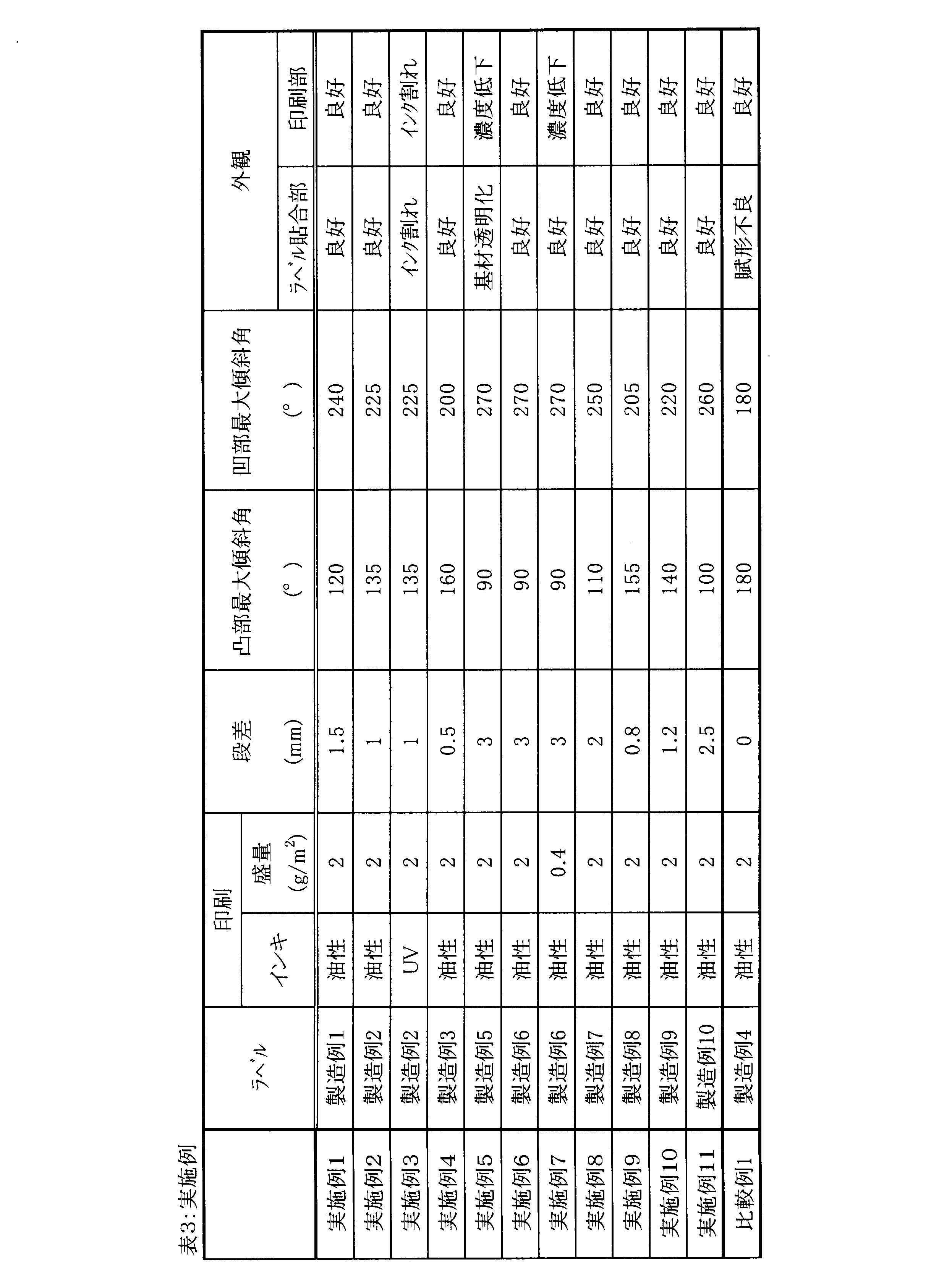
このようにして得られた中空成形容器をラベル面の凹凸部(クレーター)の中央部を通るようにレーザー変位計((株)キーエンス製、商品名:LK-G85)を用いて計測して、段差h、凸部の最大傾斜角度θ1、凹部最大傾斜角度θ2を求めた。結果を表3に合わせて示す。
得られた中空成形容器外観を形状、印刷面の状態を確認し、結果を表3に示した。
2 ブロー成形容器
11 吸引口
12 排気口
13 ブローエアー吹込み口
21,21’ ブロー成形用金型
22 凹部(金型凹部)
23 凸部(金型凸部)
101 凸部
102 凹部
Claims (13)
- 熱可塑性樹脂を含むブロー成形容器と熱可塑性樹脂フィルムを含むラベルとが熱融着して形成されるラベル付きブロー成形容器であって、
前記ラベルが貼り付けられたラベル面に凸部および凹部の一方または両方を有し、
前記ラベル面を高さ方向の基準にして、ラベル表面の最も高い部位とラベル表面の最も低い部位との距離を示す段差hが0.3mm以上であるラベル付きブロー成形容器。 - 前記凸部の側面の接線と前記ラベル面とがなす最大傾斜角度θ1が85°以上170°以下である請求項1に記載のラベル付きブロー成形容器。
- 前記凹部の側面の接線と前記ラベル面とがなす最大傾斜角度θ2が190°以上275°以下である請求項1または2に記載のラベル付きブロー成形容器。
- JIS K 7130:1999のA法で測定した、前記ラベルの厚さが20~200μmである請求項1~3の何れか1項に記載のラベル付きブロー成形容器。
- 前記熱可塑性樹脂フィルムが無延伸フィルムである請求項1~4の何れか1項に記載のラベル付きブロー成形容器。
- 前記熱可塑性樹脂フィルムが2軸延伸フィルムである請求項1~4の何れか1項に記載のラベル付きブロー成形容器。
- 前記ラベルがポリオレフィン系樹脂およびポリエステル系樹脂からなる群から選ばれる少なくとも1つの樹脂から形成された層を少なくとも1層含む請求項1~6の何れか1項に記載のラベル付きブロー成形容器。
- 前記ブロー成形容器に含まれる熱可塑性樹脂がポリオレフィン系樹脂、ポリエステル系樹脂、ポリカーボネート系樹脂およびポリスチレン系樹脂からなる群から選ばれる1以上である請求項1~7の何れか1項に記載のラベル付きブロー成形容器。
- 前記ラベルが印刷情報を有する請求項1~8の何れか1項に記載のラベル付きブロー成形容器。
- 前記印刷情報が油性インキまたは放射線硬化型インキにより形成される請求項9に記載のラベル付きブロー成形容器。
- 前記印刷情報がベタ印刷換算で0.5~6g/m2のインキ量で形成される請求項9または10に記載のラベル付きブロー成形容器。
- キャビティを有するブロー成形用金型であって、
前記金型の内壁面のラベルと接する部位に凸部および凹部の一方または両方を有し、前記内壁面の垂直方向を高さ方向の基準にして、内壁面の最も高い部位と内壁面の最も低い部位との距離を示す段差Hが0.3mm以上であるブロー成形用金型。 - 熱可塑性樹脂を含むブロー成形容器と熱可塑性樹脂フィルムを含むラベルとを熱融着させてラベル付きブロー成形容器を形成するために用いられる請求項12に記載のブロー成形用金型。
Priority Applications (6)
| Application Number | Priority Date | Filing Date | Title |
|---|---|---|---|
| JP2016531431A JPWO2016002862A1 (ja) | 2014-07-01 | 2015-07-01 | ラベル付きブロー成形容器及びブロー成形用金型 |
| BR112016030889A BR112016030889A2 (pt) | 2014-07-01 | 2015-07-01 | Recipiente marcado moldado por sopro, e, molde para moldagem por sopro |
| MX2016017292A MX2016017292A (es) | 2014-07-01 | 2015-07-01 | Recipiente moldeado por soplado etiquetado y molde de moldeo por soplado. |
| EP15815259.5A EP3165474A4 (en) | 2014-07-01 | 2015-07-01 | Labeled blow molded container and mold for blow molding |
| KR1020167036450A KR20170023862A (ko) | 2014-07-01 | 2015-07-01 | 라벨이 부착된 블로 성형 용기 및 블로 성형용 금형 |
| US15/322,574 US20170129654A1 (en) | 2014-07-01 | 2015-07-01 | Labeled blow-molded container and blow molding mold |
Applications Claiming Priority (2)
| Application Number | Priority Date | Filing Date | Title |
|---|---|---|---|
| CN201420361292.7U CN203921422U (zh) | 2014-07-01 | 2014-07-01 | 带标签的吹塑成形容器及吹塑成型用模具 |
| CN201420361292.7 | 2014-07-01 |
Publications (1)
| Publication Number | Publication Date |
|---|---|
| WO2016002862A1 true WO2016002862A1 (ja) | 2016-01-07 |
Family
ID=51817282
Family Applications (1)
| Application Number | Title | Priority Date | Filing Date |
|---|---|---|---|
| PCT/JP2015/069075 Ceased WO2016002862A1 (ja) | 2014-07-01 | 2015-07-01 | ラベル付きブロー成形容器及びブロー成形用金型 |
Country Status (9)
| Country | Link |
|---|---|
| US (1) | US20170129654A1 (ja) |
| EP (1) | EP3165474A4 (ja) |
| JP (1) | JPWO2016002862A1 (ja) |
| KR (1) | KR20170023862A (ja) |
| CN (1) | CN203921422U (ja) |
| BR (1) | BR112016030889A2 (ja) |
| MX (1) | MX2016017292A (ja) |
| TW (1) | TWI552928B (ja) |
| WO (1) | WO2016002862A1 (ja) |
Cited By (1)
| Publication number | Priority date | Publication date | Assignee | Title |
|---|---|---|---|---|
| JP2019147351A (ja) * | 2018-02-28 | 2019-09-05 | 株式会社吉野工業所 | 加飾成形体 |
Families Citing this family (6)
| Publication number | Priority date | Publication date | Assignee | Title |
|---|---|---|---|---|
| CN104077956B (zh) * | 2013-03-28 | 2017-05-17 | 优泊公司 | 模内成型用标签及使用其的带标签的塑料容器 |
| US10810909B2 (en) | 2016-06-28 | 2020-10-20 | Yupo Corporation | Labeled molded container having light contrast at three-dimensional end portion |
| CN107571480B (zh) * | 2016-07-04 | 2020-11-06 | 边宇弘 | 具有模内标签及立体形状的压力容器的制造方法 |
| US10807898B2 (en) * | 2018-03-16 | 2020-10-20 | Owens-Brockway Glass Container Inc. | Glass container with embossed indicia |
| CN113710456A (zh) * | 2019-04-26 | 2021-11-26 | 京洛株式会社 | 后备箱隔板 |
| EP4067043A4 (en) * | 2019-11-25 | 2023-11-22 | Nissei Asb Machine Co., Ltd. | Method and device for manufacturing resin-made container |
Citations (4)
| Publication number | Priority date | Publication date | Assignee | Title |
|---|---|---|---|---|
| JPH02139327A (ja) * | 1988-11-17 | 1990-05-29 | Ueno Hiroshi | ラベル付中空容器の製法 |
| WO2005054066A1 (ja) * | 2003-12-05 | 2005-06-16 | Dai Nippon Printing Co., Ltd. | インモールド容器およびその製造装置 |
| JP2012018346A (ja) * | 2010-07-09 | 2012-01-26 | Yoshino Kogyosho Co Ltd | インモールドラベル、インモールド成形品、及びインモールドラベルの製造方法 |
| JP2013043935A (ja) * | 2011-08-24 | 2013-03-04 | Fujifilm Corp | インクジェットインク組成物、インクジェット記録方法、加飾シート、及び、インモールド成形方法 |
Family Cites Families (8)
| Publication number | Priority date | Publication date | Assignee | Title |
|---|---|---|---|---|
| GB1227083A (ja) * | 1968-07-11 | 1971-03-31 | ||
| US4662528A (en) * | 1985-06-28 | 1987-05-05 | Plastipak Packaging, Inc. | Blow molded plastic container having plastic label |
| EP1099641A4 (en) * | 1999-02-27 | 2009-03-18 | Yoshino Kogyosho Co Ltd | PLASTIC TANK WITH LABEL |
| JP4171558B2 (ja) | 1999-07-30 | 2008-10-22 | 株式会社吉野工業所 | 円筒状の耐熱性中空容器 |
| AU2003208103A1 (en) * | 2002-02-04 | 2003-09-02 | Yupo Corporation | Label for in-mold molding |
| JP5660431B2 (ja) | 2010-05-31 | 2015-01-28 | 株式会社吉野工業所 | ラベル付き容器 |
| EP2468643A1 (en) * | 2010-12-23 | 2012-06-27 | KPSS-Kao Professional Salon Services GmbH | Container having a labeled textured surface |
| JP5700335B2 (ja) | 2011-02-28 | 2015-04-15 | 株式会社吉野工業所 | インモールドラベル付き薄肉容器 |
-
2014
- 2014-07-01 CN CN201420361292.7U patent/CN203921422U/zh not_active Expired - Lifetime
- 2014-12-05 TW TW103142477A patent/TWI552928B/zh active
-
2015
- 2015-07-01 US US15/322,574 patent/US20170129654A1/en not_active Abandoned
- 2015-07-01 KR KR1020167036450A patent/KR20170023862A/ko not_active Withdrawn
- 2015-07-01 MX MX2016017292A patent/MX2016017292A/es unknown
- 2015-07-01 BR BR112016030889A patent/BR112016030889A2/pt not_active Application Discontinuation
- 2015-07-01 WO PCT/JP2015/069075 patent/WO2016002862A1/ja not_active Ceased
- 2015-07-01 JP JP2016531431A patent/JPWO2016002862A1/ja active Pending
- 2015-07-01 EP EP15815259.5A patent/EP3165474A4/en not_active Withdrawn
Patent Citations (4)
| Publication number | Priority date | Publication date | Assignee | Title |
|---|---|---|---|---|
| JPH02139327A (ja) * | 1988-11-17 | 1990-05-29 | Ueno Hiroshi | ラベル付中空容器の製法 |
| WO2005054066A1 (ja) * | 2003-12-05 | 2005-06-16 | Dai Nippon Printing Co., Ltd. | インモールド容器およびその製造装置 |
| JP2012018346A (ja) * | 2010-07-09 | 2012-01-26 | Yoshino Kogyosho Co Ltd | インモールドラベル、インモールド成形品、及びインモールドラベルの製造方法 |
| JP2013043935A (ja) * | 2011-08-24 | 2013-03-04 | Fujifilm Corp | インクジェットインク組成物、インクジェット記録方法、加飾シート、及び、インモールド成形方法 |
Non-Patent Citations (1)
| Title |
|---|
| See also references of EP3165474A4 * |
Cited By (1)
| Publication number | Priority date | Publication date | Assignee | Title |
|---|---|---|---|---|
| JP2019147351A (ja) * | 2018-02-28 | 2019-09-05 | 株式会社吉野工業所 | 加飾成形体 |
Also Published As
| Publication number | Publication date |
|---|---|
| KR20170023862A (ko) | 2017-03-06 |
| BR112016030889A2 (pt) | 2017-08-22 |
| CN203921422U (zh) | 2014-11-05 |
| JPWO2016002862A1 (ja) | 2017-05-25 |
| TWI552928B (zh) | 2016-10-11 |
| US20170129654A1 (en) | 2017-05-11 |
| EP3165474A4 (en) | 2018-03-07 |
| TW201601977A (zh) | 2016-01-16 |
| EP3165474A1 (en) | 2017-05-10 |
| MX2016017292A (es) | 2017-08-24 |
Similar Documents
| Publication | Publication Date | Title |
|---|---|---|
| JPWO2016002862A1 (ja) | ラベル付きブロー成形容器及びブロー成形用金型 | |
| JP3142602B2 (ja) | ラベルの付着した中空容器の製造方法 | |
| CN101821167B (zh) | 注塑成形复合容器及其制造方法 | |
| RU2688597C2 (ru) | Пленка из термопластичной смолы и способ ее изготовления, вплавляемая этикетка, пластмассовая емкость с этикеткой и способ ее изготовления | |
| TWI651200B (zh) | 薄膜及附標籤塑膠容器 | |
| US11975511B2 (en) | In-mold label, and container with in-mold label | |
| ES2397869T3 (es) | Película de etiqueta para etiquetas envolventes | |
| JPWO2000036040A1 (ja) | ラベル | |
| WO2004026577A1 (ja) | 形状記憶ポリブチレンテレフタレート積層フィルム及びその製造方法及び用途、並びにポリブチレンテレフタレートフィルムの製造方法 | |
| WO2000017839A1 (en) | Transparent label | |
| CN106157802A (zh) | 具有网络结构的标签材料、模内标签及其制备方法和包装容器 | |
| CA2758758C (en) | Label film | |
| GB2428402A (en) | Moulded, labelled plastic article with a relief pattern. | |
| CN104640776B (zh) | 带标签中空成形容器以及中空容器成形方法 | |
| US12499783B2 (en) | Laminated body, heat-sensitive label, in-mold label and labeled container | |
| JP2000047588A (ja) | インモールド成形用ラベル | |
| JP7665010B2 (ja) | ラベル付き容器 | |
| JP2011194702A (ja) | 積層フィルムおよびそれを用いた成型用シート | |
| JP5753937B1 (ja) | インモールドラベル及びラベル付きプラスチック容器 | |
| CN203512199U (zh) | 带标签中空成形容器及模具 | |
| JP2005091594A (ja) | インモールド成形用ラベル | |
| WO2023027180A1 (ja) | インモールドラベル及びラベル付き容器 | |
| US10810909B2 (en) | Labeled molded container having light contrast at three-dimensional end portion | |
| JPH0388579A (ja) | 透明ラベル |
Legal Events
| Date | Code | Title | Description |
|---|---|---|---|
| 121 | Ep: the epo has been informed by wipo that ep was designated in this application |
Ref document number: 15815259 Country of ref document: EP Kind code of ref document: A1 |
|
| ENP | Entry into the national phase |
Ref document number: 2016531431 Country of ref document: JP Kind code of ref document: A |
|
| WWE | Wipo information: entry into national phase |
Ref document number: MX/A/2016/017292 Country of ref document: MX |
|
| REEP | Request for entry into the european phase |
Ref document number: 2015815259 Country of ref document: EP |
|
| WWE | Wipo information: entry into national phase |
Ref document number: 2015815259 Country of ref document: EP |
|
| ENP | Entry into the national phase |
Ref document number: 20167036450 Country of ref document: KR Kind code of ref document: A |
|
| WWE | Wipo information: entry into national phase |
Ref document number: 15322574 Country of ref document: US |
|
| NENP | Non-entry into the national phase |
Ref country code: DE |
|
| REG | Reference to national code |
Ref country code: BR Ref legal event code: B01A Ref document number: 112016030889 Country of ref document: BR |
|
| ENP | Entry into the national phase |
Ref document number: 112016030889 Country of ref document: BR Kind code of ref document: A2 Effective date: 20161229 |