WO2016002893A1 - 電気掃除機 - Google Patents
電気掃除機 Download PDFInfo
- Publication number
- WO2016002893A1 WO2016002893A1 PCT/JP2015/069169 JP2015069169W WO2016002893A1 WO 2016002893 A1 WO2016002893 A1 WO 2016002893A1 JP 2015069169 W JP2015069169 W JP 2015069169W WO 2016002893 A1 WO2016002893 A1 WO 2016002893A1
- Authority
- WO
- WIPO (PCT)
- Prior art keywords
- dust
- cleaning unit
- autonomous cleaning
- unit
- vacuum cleaner
- Prior art date
- Legal status (The legal status is an assumption and is not a legal conclusion. Google has not performed a legal analysis and makes no representation as to the accuracy of the status listed.)
- Ceased
Links
Images










Classifications
-
- A—HUMAN NECESSITIES
- A47—FURNITURE; DOMESTIC ARTICLES OR APPLIANCES; COFFEE MILLS; SPICE MILLS; SUCTION CLEANERS IN GENERAL
- A47L—DOMESTIC WASHING OR CLEANING; SUCTION CLEANERS IN GENERAL
- A47L9/00—Details or accessories of suction cleaners, e.g. mechanical means for controlling the suction or for effecting pulsating action; Storing devices specially adapted to suction cleaners or parts thereof; Carrying-vehicles specially adapted for suction cleaners
- A47L9/28—Installation of the electric equipment, e.g. adaptation or attachment to the suction cleaner; Controlling suction cleaners by electric means
- A47L9/2868—Arrangements for power supply of vacuum cleaners or the accessories thereof
- A47L9/2873—Docking units or charging stations
-
- A—HUMAN NECESSITIES
- A47—FURNITURE; DOMESTIC ARTICLES OR APPLIANCES; COFFEE MILLS; SPICE MILLS; SUCTION CLEANERS IN GENERAL
- A47L—DOMESTIC WASHING OR CLEANING; SUCTION CLEANERS IN GENERAL
- A47L9/00—Details or accessories of suction cleaners, e.g. mechanical means for controlling the suction or for effecting pulsating action; Storing devices specially adapted to suction cleaners or parts thereof; Carrying-vehicles specially adapted for suction cleaners
- A47L9/10—Filters; Dust separators; Dust removal; Automatic exchange of filters
- A47L9/16—Arrangement or disposition of cyclones or other devices with centrifugal action
- A47L9/1691—Mounting or coupling means for cyclonic chamber or dust receptacles
-
- A—HUMAN NECESSITIES
- A47—FURNITURE; DOMESTIC ARTICLES OR APPLIANCES; COFFEE MILLS; SPICE MILLS; SUCTION CLEANERS IN GENERAL
- A47L—DOMESTIC WASHING OR CLEANING; SUCTION CLEANERS IN GENERAL
- A47L9/00—Details or accessories of suction cleaners, e.g. mechanical means for controlling the suction or for effecting pulsating action; Storing devices specially adapted to suction cleaners or parts thereof; Carrying-vehicles specially adapted for suction cleaners
- A47L9/10—Filters; Dust separators; Dust removal; Automatic exchange of filters
- A47L9/106—Dust removal
-
- A—HUMAN NECESSITIES
- A47—FURNITURE; DOMESTIC ARTICLES OR APPLIANCES; COFFEE MILLS; SPICE MILLS; SUCTION CLEANERS IN GENERAL
- A47L—DOMESTIC WASHING OR CLEANING; SUCTION CLEANERS IN GENERAL
- A47L9/00—Details or accessories of suction cleaners, e.g. mechanical means for controlling the suction or for effecting pulsating action; Storing devices specially adapted to suction cleaners or parts thereof; Carrying-vehicles specially adapted for suction cleaners
- A47L9/10—Filters; Dust separators; Dust removal; Automatic exchange of filters
- A47L9/12—Dry filters
- A47L9/122—Dry filters flat
-
- A—HUMAN NECESSITIES
- A47—FURNITURE; DOMESTIC ARTICLES OR APPLIANCES; COFFEE MILLS; SPICE MILLS; SUCTION CLEANERS IN GENERAL
- A47L—DOMESTIC WASHING OR CLEANING; SUCTION CLEANERS IN GENERAL
- A47L9/00—Details or accessories of suction cleaners, e.g. mechanical means for controlling the suction or for effecting pulsating action; Storing devices specially adapted to suction cleaners or parts thereof; Carrying-vehicles specially adapted for suction cleaners
- A47L9/10—Filters; Dust separators; Dust removal; Automatic exchange of filters
- A47L9/14—Bags or the like; Rigid filtering receptacles; Attachment of, or closures for, bags or receptacles
- A47L9/1409—Rigid filtering receptacles
-
- A—HUMAN NECESSITIES
- A47—FURNITURE; DOMESTIC ARTICLES OR APPLIANCES; COFFEE MILLS; SPICE MILLS; SUCTION CLEANERS IN GENERAL
- A47L—DOMESTIC WASHING OR CLEANING; SUCTION CLEANERS IN GENERAL
- A47L9/00—Details or accessories of suction cleaners, e.g. mechanical means for controlling the suction or for effecting pulsating action; Storing devices specially adapted to suction cleaners or parts thereof; Carrying-vehicles specially adapted for suction cleaners
- A47L9/28—Installation of the electric equipment, e.g. adaptation or attachment to the suction cleaner; Controlling suction cleaners by electric means
-
- A—HUMAN NECESSITIES
- A47—FURNITURE; DOMESTIC ARTICLES OR APPLIANCES; COFFEE MILLS; SPICE MILLS; SUCTION CLEANERS IN GENERAL
- A47L—DOMESTIC WASHING OR CLEANING; SUCTION CLEANERS IN GENERAL
- A47L9/00—Details or accessories of suction cleaners, e.g. mechanical means for controlling the suction or for effecting pulsating action; Storing devices specially adapted to suction cleaners or parts thereof; Carrying-vehicles specially adapted for suction cleaners
- A47L9/28—Installation of the electric equipment, e.g. adaptation or attachment to the suction cleaner; Controlling suction cleaners by electric means
- A47L9/2868—Arrangements for power supply of vacuum cleaners or the accessories thereof
-
- A—HUMAN NECESSITIES
- A47—FURNITURE; DOMESTIC ARTICLES OR APPLIANCES; COFFEE MILLS; SPICE MILLS; SUCTION CLEANERS IN GENERAL
- A47L—DOMESTIC WASHING OR CLEANING; SUCTION CLEANERS IN GENERAL
- A47L9/00—Details or accessories of suction cleaners, e.g. mechanical means for controlling the suction or for effecting pulsating action; Storing devices specially adapted to suction cleaners or parts thereof; Carrying-vehicles specially adapted for suction cleaners
- A47L9/28—Installation of the electric equipment, e.g. adaptation or attachment to the suction cleaner; Controlling suction cleaners by electric means
- A47L9/2868—Arrangements for power supply of vacuum cleaners or the accessories thereof
- A47L9/2884—Details of arrangements of batteries or their installation
-
- A—HUMAN NECESSITIES
- A47—FURNITURE; DOMESTIC ARTICLES OR APPLIANCES; COFFEE MILLS; SPICE MILLS; SUCTION CLEANERS IN GENERAL
- A47L—DOMESTIC WASHING OR CLEANING; SUCTION CLEANERS IN GENERAL
- A47L9/00—Details or accessories of suction cleaners, e.g. mechanical means for controlling the suction or for effecting pulsating action; Storing devices specially adapted to suction cleaners or parts thereof; Carrying-vehicles specially adapted for suction cleaners
- A47L9/28—Installation of the electric equipment, e.g. adaptation or attachment to the suction cleaner; Controlling suction cleaners by electric means
- A47L9/2894—Details related to signal transmission in suction cleaners
-
- A—HUMAN NECESSITIES
- A47—FURNITURE; DOMESTIC ARTICLES OR APPLIANCES; COFFEE MILLS; SPICE MILLS; SUCTION CLEANERS IN GENERAL
- A47L—DOMESTIC WASHING OR CLEANING; SUCTION CLEANERS IN GENERAL
- A47L2201/00—Robotic cleaning machines, i.e. with automatic control of the travelling movement or the cleaning operation
- A47L2201/02—Docking stations; Docking operations
-
- A—HUMAN NECESSITIES
- A47—FURNITURE; DOMESTIC ARTICLES OR APPLIANCES; COFFEE MILLS; SPICE MILLS; SUCTION CLEANERS IN GENERAL
- A47L—DOMESTIC WASHING OR CLEANING; SUCTION CLEANERS IN GENERAL
- A47L2201/00—Robotic cleaning machines, i.e. with automatic control of the travelling movement or the cleaning operation
- A47L2201/02—Docking stations; Docking operations
- A47L2201/022—Recharging of batteries
-
- A—HUMAN NECESSITIES
- A47—FURNITURE; DOMESTIC ARTICLES OR APPLIANCES; COFFEE MILLS; SPICE MILLS; SUCTION CLEANERS IN GENERAL
- A47L—DOMESTIC WASHING OR CLEANING; SUCTION CLEANERS IN GENERAL
- A47L2201/00—Robotic cleaning machines, i.e. with automatic control of the travelling movement or the cleaning operation
- A47L2201/02—Docking stations; Docking operations
- A47L2201/024—Emptying dust or waste liquid containers
-
- A—HUMAN NECESSITIES
- A47—FURNITURE; DOMESTIC ARTICLES OR APPLIANCES; COFFEE MILLS; SPICE MILLS; SUCTION CLEANERS IN GENERAL
- A47L—DOMESTIC WASHING OR CLEANING; SUCTION CLEANERS IN GENERAL
- A47L2201/00—Robotic cleaning machines, i.e. with automatic control of the travelling movement or the cleaning operation
- A47L2201/04—Automatic control of the travelling movement; Automatic obstacle detection
Definitions
- the embodiment according to the present invention relates to a vacuum cleaner.
- an electric vacuum cleaner comprising an autonomous cleaning unit that autonomously moves a surface to be cleaned and collects dust on the surface to be cleaned, and a station unit that accumulates dust collected by the autonomous cleaning unit. Yes.
- the autonomous cleaning unit autonomously moves to the dust discharge position of the trapezoidal station unit, and the dust collected by the autonomous cleaning unit is collected by its own weight by using the fall of the dust by its own weight. Drop and collect in a dust container in the station unit.
- the present invention proposes a vacuum cleaner that can fluidly connect the dust container in the autonomous cleaning unit and the station unit by utilizing the propulsive force of the autonomous cleaning unit that moves to the dust discharge position.
- an electric vacuum cleaner includes an autonomous cleaning unit that autonomously moves a surface to be cleaned and collects dust on the surface to be cleaned, and a charging electrode of the autonomous cleaning unit.
- the autonomous cleaning unit includes a main body case, a container body that is provided in the main body case and accumulates dust collected by the autonomous cleaning unit, a disposal port that discards dust in the container body, and the disposal port And a primary dust container having a waste lid for opening and closing.
- the station unit includes a dust transfer pipe connected to the disposal port of the primary dust container, and is caught on the disposal lid while the autonomous cleaning unit returns, and opens the disposal lid to open the disposal port and the dust.
- a lever that fluidly connects the transfer pipe; and a secondary dust container that accumulates dust discarded from the primary dust container through the dust transfer pipe.
- the disposal lid and the lever of the vacuum cleaner according to the present invention swing around a rotation center line intersecting with the autonomous cleaning unit in a direction toward the home position.
- the rotation center line of the lever of the electric vacuum cleaner according to the present invention is supported so that the autonomous cleaning unit can move in the direction toward the home position.
- the waste lid of the vacuum cleaner according to the present invention includes a lever receiver that hooks the lever, and a rotation center line of the waste lid is a position where the autonomous cleaning unit is electrically connected to the charging electrode. It is preferable that it is arrange
- the rotation center line of the lever of the electric vacuum cleaner according to the present invention is such that the autonomous cleaning unit first reaches the opening edge of the dust transfer pipe in the direction in which the autonomous cleaning unit moves toward the homing position. It is preferable to arrange at the edge.
- the waste cover of the electric vacuum cleaner according to the present invention has an inclined surface that guides dust from the container body to the dust transfer pipe when opened by the lever.
- the primary dust container of the electric vacuum cleaner according to the present invention is detachable from the main body case.
- the disposal lid of the vacuum cleaner according to the present invention is exposed to the appearance of the autonomous cleaning unit.
- the homing position of the electric vacuum cleaner according to the present invention is a position where the autonomous cleaning unit is connected to the charging electrode.
- the perspective view which shows the external appearance of the vacuum cleaner which concerns on embodiment of this invention The perspective view which shows the bottom face of the autonomous cleaning unit of the vacuum cleaner which concerns on embodiment of this invention.
- the longitudinal cross-sectional view which shows the connection part of the autonomous type cleaning unit and station unit of the vacuum cleaner which concerns on embodiment of this invention.
- the longitudinal cross-sectional view which shows the connection part of the autonomous type cleaning unit and station unit of the vacuum cleaner which concerns on embodiment of this invention The longitudinal cross-sectional view which shows the connection part of the autonomous type cleaning unit and station unit of the vacuum cleaner which concerns on embodiment of this invention.
- the longitudinal cross-sectional view which shows the connection part of the autonomous type cleaning unit and station unit of the vacuum cleaner which concerns on embodiment of this invention.
- the longitudinal cross-sectional view which shows the connection part of the autonomous type cleaning unit and station unit of the vacuum cleaner which concerns on embodiment of this invention.
- the longitudinal cross-sectional view which shows the connection part of the autonomous type cleaning unit and station unit of the vacuum cleaner which concerns on embodiment of this invention.
- the longitudinal cross-sectional view which shows the connection part of the autonomous type cleaning unit and station unit of the vacuum cleaner which concerns on embodiment of this invention.
- the longitudinal cross-sectional view which shows the connection part of the autonomous type cleaning unit and station unit of the vacuum cleaner which concerns on embodiment of this invention.
- the longitudinal cross-sectional view which shows the connection part of the autonomous type cleaning unit and station unit of the vacuum cleaner which concerns on embodiment of this invention.
- the cross-sectional perspective view which shows the station unit of the vacuum cleaner which concerns on embodiment of this invention.
- the cross-sectional perspective view which shows the station unit of the vacuum cleaner which concerns on embodiment of this invention.
- the cross-sectional perspective view which shows the station unit of the vacuum cleaner which concerns on embodiment of this invention.
- the perspective view which shows the secondary dust container of the vacuum cleaner which concerns on embodiment of this invention.
- the perspective view which shows the secondary dust container of the vacuum cleaner which concerns on embodiment of this invention.
- FIG. 1 is a perspective view showing an appearance of a vacuum cleaner according to an embodiment of the present invention.
- the vacuum cleaner 1 includes an autonomous cleaning unit 2 that autonomously moves a surface to be cleaned and collects dust on the surface to be cleaned, and an autonomous cleaning.
- the vacuum cleaner 1 autonomously moves the autonomous cleaning unit 2 over the entire surface to be cleaned in the living room to collect dust, and thereafter returns the autonomous cleaning unit 2 to the station unit 5. Dust collected by the autonomous cleaning unit 2 is taken to the station unit 5 side and collected.
- the position where the autonomous cleaning unit 2 is electrically connected to the charging electrode 3 of the station unit 5 is the home position of the autonomous cleaning unit 2 returning to the station unit 5. When charging is required or when the room has been cleaned, the home is returned to this home position.
- the position where the autonomous cleaning unit 2 is electrically connected to the charging electrode 3 of the station unit 5 is relative between the autonomous cleaning unit 2 that moves autonomously and the station unit 5 that can be installed at any place. It is a serious positional relationship.
- the arrow A in FIG. 1 is the forward direction of the autonomous cleaning unit 2
- the arrow B is the backward direction of the autonomous cleaning unit 2.
- the width direction of the autonomous cleaning unit 2 is a direction orthogonal to the arrows A and B.
- the autonomous cleaning unit 2 moves forward and leaves the station unit 5 and travels autonomously in the living room. On the other hand, when returning to the station unit 5, the autonomous cleaning unit 2 moves backward and connects to the station unit 5.
- the autonomous cleaning unit 2 is a so-called robot cleaner.
- the autonomous cleaning unit 2 includes a hollow disk-shaped main body case 11, a primary dust container 12 that is detachably provided at a rear portion of the main body case 11, and a primary that is accommodated in the main body case 11 and connected to the primary dust container 12.
- the electric blower 13 the moving unit 15 for moving the autonomous cleaning unit 2 on the surface to be cleaned, the driving unit 16 for driving the moving unit 15, and the driving unit 16 to control the body case 11 on the surface to be cleaned autonomously.
- a secondary battery 18 as a power source.
- the station unit 5 is installed on the surface to be cleaned.
- the station unit 5 includes a pedestal 21 on which the autonomous cleaning unit 2 heads for a position (homing position) electrically connected to the charging electrode 3, a dust collecting unit 22 integrated with the pedestal 21, and the charging electrode 3.
- a dust transfer tube 25 that is airtightly connected to the primary dust container 12 of the autonomous cleaning unit 2, a lever 26 that protrudes from the dust transfer tube 25, and a power cord 29 that guides power from a commercial AC power source. .
- FIG. 2 is a perspective view showing a bottom surface of the autonomous cleaning unit of the electric vacuum cleaner according to the embodiment of the present invention.
- the autonomous cleaning unit 2 of the vacuum cleaner 1 includes a center brush 31 provided on the bottom surface 11 a of the main body case 11 and a center brush drive that drives the center brush 31.
- the disk-shaped main body case 11 is made of, for example, a synthetic resin, and can easily turn the surface to be cleaned.
- a horizontally long suction port 36 is provided at the center in the width direction of the rear half of the bottom surface 11a.
- the suction port 36 has a width dimension of the main body case 11, that is, a width dimension of about two thirds of the diameter dimension.
- the suction port 36 is fluidly connected to the primary electric blower 13 through the primary dust container 12.
- the main body case 11 has a dust container opening 37 on the bottom surface 11a.
- the dust container port 37 is disposed in a portion covering the lower part of the primary dust container 12.
- the dust container opening 37 is opened in a rounded rectangular shape to partially expose the primary dust container 12 attached to the main body case 11.
- the primary dust container 12 accumulates the dust sucked from the suction port 36 by the suction negative pressure generated by the primary electric blower 13.
- a filter that collects and collects dust, a separation device that accumulates dust by inertial separation such as centrifugal separation (cyclonic separation) and straight separation, and the like are applied to the primary dust container 12.
- the primary dust container 12 is disposed at the rear part of the main body case 11.
- the primary dust container 12 is detachably provided on the main body case 11 and is exposed from the dust container mouth 37 when attached to the main body case 11 and a container main body 38 that accumulates dust collected by the autonomous cleaning unit 2.
- a connecting portion 39, a discard port 41 provided at the connecting portion 39 for discarding the dust in the container main body 38, and a disposal lid 42 for opening and closing the discard port 41 are provided.
- the moving unit 15 includes a pair of left and right drive wheels 45 disposed on the bottom surface 11 a of the main body case 11 and a turning wheel 46 disposed on the bottom surface 11 a of the main body case 11.
- the pair of drive wheels 45 protrude from the bottom surface 11a of the main body case 11, and are grounded to the surface to be cleaned with the autonomous cleaning unit 2 placed on the surface to be cleaned. Further, the pair of drive wheels 45 is disposed at a substantially central portion in the front-rear direction of the main body case 11, and is disposed close to the left and right side portions of the main body case 11 while avoiding the front of the suction port 36.
- the rotation shafts of the pair of drive wheels 45 are arranged on a straight line extending along the width direction of the main body case 11.
- the autonomous cleaning unit 2 moves forward or backward by rotating the left and right drive wheels 45 in the same direction, and turns clockwise or counterclockwise by rotating the left and right drive wheels 45 in opposite directions.
- the turning wheel 46 is a driven wheel that can turn freely.
- the main body case 11 is disposed at a substantially central portion in the width direction and at the front portion.
- the drive unit 16 is a pair of electric motors connected to each of the pair of drive wheels 45.
- the drive unit 16 drives the left and right drive wheels 45 independently of each other.
- the robot control unit 17 includes a microprocessor (not shown) and a storage device (not shown) for storing various arithmetic programs executed by the microprocessor, parameters, and the like.
- the robot control unit 17 is electrically connected to the primary electric blower 13, the center brush drive unit 32, the drive unit 16, and the side brush drive unit 35.
- the secondary battery 18 is a power source for the primary electric blower 13, the center brush drive unit 32, the drive unit 16, the side brush drive unit 35, and the robot control unit 17.
- the secondary battery 18 is disposed, for example, between the turning wheel 46 and the suction port 36.
- the secondary battery 18 is electrically connected to a pair of charging terminals 47 arranged on the bottom surface 11 a of the main body case 11.
- the secondary battery 18 is charged by connecting a charging terminal 47 to the charging electrode 3 of the station unit 5.
- the center brush 31 is provided in the suction port 36.
- the center brush 31 is an axial brush that can rotate around a rotation center line extending in the width direction of the main body case 11.
- the center brush 31 includes, for example, a long shaft portion and a plurality of brushes extending in the radial direction of the shaft portion and arranged in a spiral shape in the longitudinal direction of the shaft portion.
- the center brush 31 projects downward from the bottom surface 11a of the main body case 11 through the suction port 36, and makes the brush contact the surface to be cleaned with the autonomous cleaning unit 2 placed on the surface to be cleaned.
- the center brush drive unit 32 is accommodated in the main body case 11.
- the pair of side brushes 33 are arranged on the left and right sides with respect to the forward direction of the center brush 31, and auxiliary cleaning bodies that scrape dust on the surface to be cleaned near the wall where the center brush 31 does not reach and guide it to the suction port 36. It is.
- Each of the side brushes 33 includes a brush base 48 having a center of rotation that slightly tilts forward with respect to the normal to the surface to be cleaned, and, for example, three linear cleaning bodies 49 that protrude radially in the radial direction of the brush base 48. It is equipped with.
- the left and right brush bases 48 are arranged in front of the suction port 36 and the left and right drive wheels 45 and rearward of the swivel wheel 46 and closer to the left and right sides of the suction port 36. Further, the rotation center line of each brush base 48 is slightly inclined forward with respect to the normal of the surface to be cleaned. For this reason, the linear cleaning body 49 is turning along the surface inclined forward with respect to the surface to be cleaned. The linear cleaning body 49 turning to the front side from the brush base 48 is pressed against the surface to be cleaned toward the tip side, and the linear cleaning body 49 turning to the rear side from the brush base portion 48 is cleaned toward the tip side. You will leave the face.
- the plurality of linear cleaning bodies 49 are arranged radially from the brush base 48, for example, at equal intervals in three directions.
- the side brush 33 may include four or more linear cleaning bodies 49 for each brush base 48.
- Each linear cleaning body 49 includes a plurality of brush hairs as cleaning members on the tip side. Further, the brush bristles swirl while drawing a trajectory extending outward from the outer peripheral edge of the main body case 11.
- Each side brush drive unit 35 includes a rotating shaft that protrudes downward and is connected to the brush base 48 of the side brush 33. Each side brush drive unit 35 rotates the side brush 33 so as to scrape dust on the surface to be cleaned to the suction port 36.
- station unit 5 according to the embodiment of the present invention will be described in detail.
- FIG. 3 is a perspective view showing a station unit of the vacuum cleaner according to the embodiment of the present invention.
- the pedestal 21 of the station unit 5 projects to the front side of the station unit 5 and expands into a rectangular shape.
- the pedestal 21 includes a high floor portion 61 that is connected to the bottom of the dust collection portion 22, and a low floor portion 62 that projects from the high floor portion 61.
- the low floor portion 62 and the high floor portion 61 extend in a band shape in the width direction of the station unit 5.
- a roller pair 23 is disposed on the low floor portion 62.
- the charging electrode 3 and the entrance of the dust transfer tube 25 are arranged.
- the autonomous cleaning unit 2 rides the pair of driving wheels 45 on the low floor 62 and reaches the homing position with the primary dust container 12 disposed above the high floor 61.
- the roller pair 23 is disposed at each of the left and right ends of the low floor 62 of the base 21 and the front end.
- the roller pair 23 guides the autonomous cleaning unit 2 in a direction crossing a direction (retracting direction) toward the position (homing position) where the autonomous cleaning unit 2 is electrically connected to the charging electrode 3, that is, in the width direction.
- a pair of cross-direction rollers 63, a pair of stop rollers 65 that idle each of the pair of drive wheels 45 when reaching the position (home position) where the autonomous cleaning unit 2 is electrically connected to the charging electrode 3, It has.
- the pair of rollers 23, that is, the pair of cross-direction rollers 63 and the pair of stop rollers 65 protrude from the pedestal 21 as the ground contact surface of the pair of drive wheels 45.
- the pair of cross-direction rollers 63 have a non-parallel rotation center C1 whose separation distance is narrowed toward a position (home position) where the autonomous cleaning unit 2 is electrically connected to the charging electrode 3.
- the pair of cross-direction rollers 63 have a rotation center C1 that approaches each other as it approaches the dust collection unit 22 from the pedestal 21 side.
- the pair of stop rollers 65 have a rotation center C2 that intersects in a direction toward the position (home position) where the autonomous cleaning unit 2 is electrically connected to the charging electrode 3.
- the pair of stop rollers 65 idle each of the pair of driving wheels 45 to advance the autonomous cleaning unit 2. Stop (retreat).
- the rotation center C2 of the pair of stop rollers 65 is preferably orthogonal to the direction toward the position (home position) where the autonomous cleaning unit 2 is electrically connected to the charging electrode 3.
- the pedestal 21 includes an uneven running surface 66 that reduces the ground contact area of each of the pair of drive wheels 45 when the autonomous cleaning unit 2 moves toward a position (homing position) where the autonomous cleaning unit 2 is electrically connected to the charging electrode 3. Yes.
- the running surface 66 is provided at a portion surrounded by the roller pair 23, that is, the pair of cross-direction rollers 63 and the pair of stop rollers 65.
- the running surface 66 is a plurality of linear irregularities, a lattice-shaped irregularity, or a plurality of hemispherical irregularities provided on a part of the pedestal 21.
- the dust collection unit 22 includes a secondary dust container 68 that accumulates dust discarded from the primary dust container 12 through the dust transfer pipe 25, and a secondary that is accommodated in the dust collection unit 22 and connected to the secondary dust container 68.
- An electric blower 69 and a power cord 29 for guiding electric power from a commercial AC power source to the secondary electric blower 69 and the charging electrode 3 are provided.
- the dust collecting unit 22 is a rounded rectangular box that is disposed at the rear of the station unit 5 and extends upward from the base 21.
- the front wall of the dust collection unit 22 includes an arcuate recess 71 corresponding to the rear end of the autonomous cleaning unit 2.
- the entrance of the dust transfer pipe 25 extends from the raised floor portion 61 of the pedestal 21 to the recessed portion 71.
- the recessed portion 71 is provided with a homing confirmation detector 72 that detects whether or not the autonomous cleaning unit 2 has reached a position (homing position) where the autonomous cleaning unit 2 is electrically connected to the charging electrode 3.
- the homing confirmation detection unit 72 is a so-called objective sensor that detects a relative distance from the autonomous cleaning unit 2 using visible light or infrared light.
- the homing confirmation detection unit 72 includes a first sensor unit 73 that detects a relative distance from the autonomous cleaning unit 2 in the front direction of the dust collection unit 22, and an autonomous cleaning unit 2 in the height direction of the dust collection unit 22.
- a second sensor unit 75 that detects a relative distance.
- the dust collection unit 22 includes a lid 82 that covers the secondary dust container 68 accommodated in the main body 81.
- the lid 82 opens and closes a part of the ceiling of the dust collection unit 22, specifically, the right half.
- a secondary dust container 68 is disposed below the lid 82.
- the pair of charging electrodes 3 are arranged with the entrance of the dust transfer tube 25 interposed therebetween. Each charging electrode 3 is arranged in front of the left and right edges of the recessed portion 71.
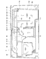
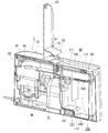
- FIG. 4 is a longitudinal section showing a station unit of a vacuum cleaner according to an embodiment of the present invention.
- FIG. 5 is a cross-sectional view showing the station unit of the electric vacuum cleaner according to the embodiment of the present invention.
- the dust collection unit 22 of the station unit 5 takes out a main body 81 having a dust transfer pipe 25 as an air passage for guiding the dust, and the main body 81.
- a secondary dust container 68 as a dust collecting part that is freely stored and is detachably connected to the dust transfer pipe 25, and a second vacuum that sucks the dust transfer pipe 25 through the secondary dust container 68 to generate negative pressure.
- the lid body 82 that covers the secondary dust container 68 accommodated in the main body 81, and the secondary dust container 68 provided on the lid body 82 are taken out from the main body 81
- the dust collection unit 22 is provided in the erroneous suction prevention unit 83 and regulates the swing angle of the erroneous suction prevention unit 83 when the lid 82 is in contact with the secondary dust container 68 during the closing process.
- a claw 87 is provided to direct the sealing surface 86 that closes the air passage on the suction side of the electric blower 69 toward the secondary dust container 68.
- the dust collection unit 22 includes a pressure detection unit 91 that detects the suction negative pressure of the secondary electric blower 69 and a notification unit that notifies that the dust accumulated in the secondary dust container 68 has reached a predetermined amount. 92, and a control unit 93 that operates the notification unit 92 when the detection result of the pressure detection unit 91 is lower than a predetermined suction negative pressure.
- the main body 81 is short in the depth direction (the direction that travels when the autonomous cleaning unit 2 returns) and long in the width direction.
- the main body 81 has a dust container chamber 95 that houses the secondary dust container 68 in one half in the width direction, specifically, the right half, and the other half in the width direction, specifically, the left half.
- a blower chamber 96 that houses the secondary electric blower 69 is provided in the section.
- the dust transfer tube 25 is airtightly connected to the disposal port 41 in contact with the connecting portion 39 of the primary dust container 12 in a position (homing position) where the autonomous cleaning unit 2 is electrically connected to the charging electrode 3. .
- An annular seal member 25 a is provided at the opening edge of the dust transfer tube 25, that is, at the inlet.
- the seal member 25 a is in close contact with the connecting portion 39 in a position (homing position) where the autonomous cleaning unit 2 is electrically connected to the charging electrode 3.
- the dust transfer pipe 25 extends rearward from an inlet disposed in the high floor portion 61 of the pedestal 21, reaches the dust collecting unit 22, is bent in the dust collecting unit 22, and is disposed between the dust container chamber 95 and the blower chamber 96. To the side of the secondary dust container 68.
- the dust transfer pipe 25 has an inlet opening upward toward the station unit 5 and an outlet opening laterally toward the secondary dust container 68.
- the lever 26 disposed at the entrance of the dust transfer pipe 25 includes a hook 97 extending in the front direction and upward of the dust collection unit 22.
- the secondary dust container 68 is provided in the discharge port 103, the dust container 102 having a top surface open and having a suction port 101 on the side surface, the lid 105 having the discharge port 103 while closing the top surface of the dust container 102, and the discharge port 103.
- the net filter 106 is divided into an upstream space 107 that hangs down from the lid 105 toward the bottom surface of the dust container 102 and directly connects the inside of the dust container 102 to the suction port 101, and a downstream space 108 that connects to the discharge port 103.
- a partition plate 109 that connects the upstream space 107 and the downstream space 108 at the bottom in the dust container 102, a secondary filter 110 that is connected to the discharge port 103 and covers the cover 105, and downstream of the secondary filter 110. And a cover tube 111 that partitions the side air passage.
- the dust container 102 includes a bulging portion 112 that is disposed below the downstream space 108 and bulges downward from the bottom of the upstream space 107.
- the secondary filter 110 is connected to the downstream pipe 85.
- the secondary dust container 68 includes a first hinge mechanism 115 that integrally opens and closes the lid body 105, the partition plate 113, and the secondary filter 110, and a lid body 105 and the partition plate 113 that are integrally swung to form a secondary. And a second hinge mechanism 116 for opening and closing the space on the filtration surface side of the filter 110.
- the cover pipe 111 also serves as an air path connecting the downstream air path of the secondary filter 110 to the downstream pipe 85.
- the cover tube 111 is swingably supported by the first hinge mechanism 115 together with the lid body 105.
- the first hinge mechanism 115 is disposed above the suction port 101 and at the upper end of the side wall of the dust container 102 having the suction port 101.
- the second hinge mechanism 116 is provided at the end of the lid 105 opposite to the first hinge mechanism 115.
- the secondary electric blower 69 is accommodated in the blower chamber 96 of the main body 81 with the suction port facing upward.
- the downstream pipe 85 is an air passage on the suction side of the secondary electric blower 69 and is arranged above the dust transfer pipe 25 and extends in the width direction in the main body 81 of the dust collection unit 22.
- An inlet of the downstream pipe 85 opens into the dust container chamber 95.
- the outlet of the downstream pipe 85 is connected to the suction port of the secondary electric blower 69.
- the downstream pipe 85 is connected to the downstream side of the secondary filter 110 of the secondary dust container 68 when the secondary dust container 68 is stored in the dust container chamber 95.
- the lid 82 is swingably provided on the main body 81.
- the lid 82 opens and closes the opening on the top surface of the dust container chamber 95 that houses the secondary dust container 68.
- the erroneous suction preventing portion 83 is provided on the lid 82 so as to be swingable.
- the erroneous suction prevention unit 83 has a vent hole 121 that avoids complete blockage of the air passage on the suction side of the secondary electric blower 69.
- the charging terminal 47 of the autonomous cleaning unit 2 is electrically connected to the charging electrode 3 of the station unit 5.
- the dust transfer tube 25 of the station unit 5 is connected to the connecting portion 39 of the primary dust container 12.
- the station unit 5 drives the secondary electric blower 69 to suck air in the direction of the solid line arrow in FIGS. 4 and 5 to move the dust from the primary dust container 12 to the secondary dust container 68.
- the secondary dust container 68 supplements coarse dust with a net filter 106 and accumulates it in the downstream space 108. The dust captured by the net filter 106 is accumulated so as to be stacked from the upper side to the lower side of the downstream space 108.
- the dust captured by the net filter 106 is compressed by being pressed against the net filter 106 by the air flow.
- the compressed coarse dust serves as a fine filter and supplements fine fine dust contained in the air.
- the fine dust that is captured by the compressed coarse dust may be collected by the coarse dust, while the fine dust may be dropped from the coarse dust and reach the lower side of the downstream space 108.
- air flowing in a U shape from the upstream space 107 to the downstream space 108 in the secondary dust container 68 is likely to stagnate. For this reason, the fine dust that accumulates on the bulging portion 112 does not rise in the air flow in the secondary dust container 68 and easily collects in the bulging portion 112.
- Fine fine dust passing through the net filter 106 and fine dust passing through the compressed coarse dust are supplemented by the secondary filter 110.
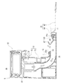
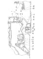
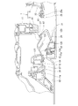
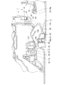
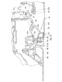
- 6 to 16 are longitudinal cross-sectional views showing a connecting portion of the autonomous cleaning unit and the station unit of the vacuum cleaner according to the embodiment of the present invention.
- FIGS. 6 to 16 show in a stepwise manner how the autonomous cleaning unit 2 approaches a position (homing position) where it is electrically connected to the charging electrode 3. Further, when the autonomous cleaning unit 2 moves away from the station unit 5, the reverse order of FIG. 16 to FIG. 6 occurs.
- the primary dust container 12 of the autonomous cleaning unit 2 is detachably provided on the main body case 11 and accumulates dust collected by the autonomous cleaning unit 2.
- the connecting portion 39 is integrally formed with the container body 38.
- the connecting portion 39 protrudes in a rounded rectangular shape corresponding to the dust container opening 37.
- the connecting portion 39 is fitted into the dust container opening 37.
- the connecting portion 39 has an outer peripheral edge that is flush with the outer surface of the main body case 11, and has a recessed portion at the peripheral edge of the disposal port 41.
- a disposal port 41 is disposed in the center of the recessed portion.
- a disposal lid 42 is disposed in the recessed portion.
- connection part 39 may be arrange
- the connecting portion 39 is disposed inside the main body case 11 at a place where it can be seen from the dust container port 37.
- the dust transfer tube 25 preferably has a protruding length that can reach the connecting portion 39 through the dust container port 37.
- the disposal port 41 is opened downward of the autonomous cleaning unit 2 in a state where the primary dust container 12 is attached to the main body case 11.
- the disposal port 41 is disposed closer to the station unit 5 than the center of the autonomous cleaning unit 2 in relation to the position (homing position) where the autonomous cleaning unit 2 is electrically connected to the charging electrode 3. That is, the disposal port 41 approaches the dust collection unit 22 of the station unit 5 when the autonomous cleaning unit 2 moves backward and approaches the station unit 5 and rides the pair of drive wheels 45 on the base 21 of the station unit 5.
- the disposal lid 42 is exposed to the external appearance of the autonomous cleaning unit 2 and is flush with the outer surface of the main body case 11.
- the waste lid 42 includes a lever receiver 123 that hooks the lever 26 of the station unit 5.
- the disposal lid 42 may also be disposed at a location facing the dust container opening 37 in a state of being attached to the main body case 11 in the same manner as the connecting portion 39. In this case, the disposal lid 42 is disposed inside the main body case 11 and can be seen from the dust container port 37.
- the lever 26 of the station unit 5 is attached to the disposal lid 42 of the autonomous cleaning unit 2 on the way to the position (home position) where the autonomous cleaning unit 2 is electrically connected to the charging electrode 3.
- the disposal lid 42 is opened and the disposal port 41 and the dust transfer pipe 25 are fluidized. (FIGS. 14 to 16).
- the disposal lid 42 of the autonomous cleaning unit 2 and the lever 26 of the station unit 5 are connected to the rotation center line C3 that intersects in the direction toward the position (homing position) where the autonomous cleaning unit 2 is electrically connected to the charging electrode 3. Swing around.
- the rotation center C4 of the disposal lid 42 and the rotation center line C3 of the lever 26 may be orthogonal to the direction toward the position (home position) where the autonomous cleaning unit 2 is electrically connected to the charging electrode 3. desirable.
- the rotation center line C3 of the lever 26 indicates that the autonomous cleaning unit 2 in the opening edge of the dust transfer tube 25 is in the direction toward the position (homing position) where the autonomous cleaning unit 2 is electrically connected to the charging electrode 3. It is arranged at the edge that reaches first, that is, at the front end of the opening edge of the dust transfer tube 25.
- the rotation center line C3 of the lever 26 is supported so as to be movable in a direction toward the position (home position) where the autonomous cleaning unit 2 is electrically connected to the charging electrode 3. That is, the rotation center line C3 of the lever 26 moves in a direction toward the position (homing position) where the autonomous cleaning unit 2 is electrically connected to the charging electrode 3, so that in the homing control of the autonomous cleaning unit 2.
- the hook 97 can be hooked on the lever receiver 123 without being affected by variations in positional accuracy.
- the rotation center line C3 of the lever 26 is an autonomous cleaning unit of the opening edge of the dust transfer tube 25 in the direction toward the position (homing position) where the autonomous cleaning unit 2 is electrically connected to the charging electrode 3. 2 is covered with a shaft cover 125 provided at the edge that reaches first, that is, the front end of the opening edge of the dust transfer tube 25.
- the rotation center line C4 of the disposal lid 42 is arranged on the far side of the disposal lid 42 in the direction toward the position (homing position) where the autonomous cleaning unit 2 is electrically connected to the charging electrode 3. Further, the rotation center line C4 of the disposal lid 42 is disposed farther than the lever receiver 123 in the direction toward the position (home position) where the autonomous cleaning unit 2 is electrically connected to the charging electrode 3. Further, the rotation center line C4 of the disposal lid 42 is in contact with or away from the disposal port 41 of the disposal lid 42 in the direction toward the position (homing position) where the autonomous cleaning unit 2 is electrically connected to the charging electrode 3. It is arranged on the far side from the lid body 126.
- the waste lid 42 guides dust from the container body 38 of the autonomous cleaning unit 2 to the dust transfer tube 25 when opened by the lever 26. (See FIG. 16).
- the disposal lid 42 receives the spring force of the coil spring 127 in the closing direction.
- the waste lid 42 is opened when the propulsive force toward the position (home position) where the autonomous cleaning unit 2 is electrically connected to the charging electrode 3 exceeds the spring force of the coil spring 127.
- the coil spring 127 is crushed and accumulates energy, while when the autonomous cleaning unit 2 leaves the station unit 5 and the lever 26 comes out of the lever receiver 123, the energy is released. Then, the waste lid 42 is closed.
- the lever 26 receives a spring force of a coil spring (not shown) in a direction to stand (FIG. 6).
- the lever 26 is pushed down when the propulsive force toward the position (home position) where the autonomous cleaning unit 2 is electrically connected to the charging electrode 3 exceeds the spring force of the coil spring.
- the coil spring is crushed and accumulates energy.
- the autonomous cleaning unit 2 leaves the station unit 5 and the lever 26 comes out of the lever receiver 123, the coil spring releases energy. To raise the lever 26.
- 17 and 18 are cross-sectional perspective views showing the station unit of the vacuum cleaner according to the embodiment of the present invention.
- FIG. 17 shows a state where the lid 82 is fully opened.
- FIG. 18 shows a state in which the erroneous suction preventing portion 83 starts to come into contact with the secondary dust container 68 while closing the lid 82.
- the station unit 5 can take out the secondary dust container 68 from the dust container chamber 95 in the main body 81 by opening the lid 82.
- the lid 82 Since the rotation center of the lid 82 is on the blower chamber 96 side, the lid 82 is opened so as to approach the blower chamber 96 side.
- the lid body 82 opens substantially vertically and opens largely above the dust container chamber 95.
- the lid 82 Since the erroneous suction preventing portion 83 is swingably supported by the lid 82, the lid 82 is in a state along the inner surface of the lid 82 when the lid 82 is closed (FIG. 5). When opened, it tilts (swings) by its own weight and falls. At this time, the claw 87 provided in the erroneous suction preventing portion 83 regulates the inclination of the erroneous suction preventing portion 83 at an appropriate angle. The appropriate angle is set to an angle at which the erroneous suction prevention portion 83 hits the secondary dust container 68 and does not hinder the closing of the lid 82 when the lid 82 is closed. That is, as shown in FIG.
- the claw 87 has an outer shell of the secondary dust container 68 and the erroneous suction prevention portion 83 when the erroneous suction prevention portion 83 contacts the secondary dust container 68 in the process of closing the lid 82.
- the inclination of the erroneous suction preventing portion 83 is appropriately adjusted so that the erroneous suction preventing portion 83 falls into a state along the inner surface of the lid 82 (FIG. 5) by further closing the lid 82. Regulated by angle.
- FIG. 19 is a cross-sectional perspective view showing the station unit of the vacuum cleaner according to the embodiment of the present invention.
- FIG. 19 shows a state where the secondary dust container 68 is removed from the station unit 5.
- the dust transfer pipe 25 and the downstream pipe 85 of the station unit 5 are fluidly connected through the dust container chamber 95 when the secondary dust container 68 is taken out from the dust container chamber 95.
- the secondary electric blower 69 When the secondary electric blower 69 is operated while the dust transfer pipe 25 and the downstream pipe 85 are fluidly connected through the dust container chamber 95, the negative pressure generated by the secondary electric blower 69 is It acts on the dust transfer pipe 25 through the dust container chamber 95. In this case, if the autonomous cleaning unit 2 returns to the home position, the dust in the primary dust container 12 may be scattered in the dust container chamber 95 or may be sucked into the secondary electric blower 69.
- the station unit 5 closes the inlet of the downstream pipe 85 by the erroneous suction preventing portion 83 when the secondary dust container 68 is taken out from the dust container chamber 95.
- the fluid connection between the downstream pipe 85 and the dust container chamber 95 is cut off.
- the secondary electric blower 69 is operated in a state where the inlet of the downstream pipe 85 is closed by the erroneous suction prevention unit 83, the negative pressure generated by the secondary electric blower 69 causes the erroneous suction prevention part 83 to enter the downstream pipe 85.
- the dust in the primary dust container 12 is scattered in the dust container chamber 95 even if the autonomous cleaning unit 2 returns to the homing position without acting on the dust transfer pipe 25.
- the next electric blower 69 is prevented from being sucked.
- the vent hole 121 of the erroneous suction preventing portion 83 allows air to flow from the dust container chamber 95 into the downstream pipe 85. Lead.
- the opening area of the vent hole 121 is sufficiently smaller than the cross-sectional area of the downstream pipe 85, and the dust in the primary dust container 12 is scattered in the dust container chamber 95 due to the negative pressure acting on the dust container chamber 95. The size is set so as to avoid being sucked into the secondary electric blower 69.
- the control unit 93 monitors the negative pressure in the downstream pipe 85 by the pressure detection unit 91. When the detection result of the pressure detection unit 91 is lower than the predetermined suction negative pressure, the control unit 93 operates the notification unit 92. Notifies that the dust accumulated in the secondary dust container 68 has reached a predetermined amount.
- the dust amount notification control of the control unit 93 functions effectively even when the secondary dust container 68 is taken out from the dust container chamber 95. In other words, the control unit 93 also notifies the notification unit when the negative suction in the downstream pipe 85 is increased by closing the erroneous suction prevention unit 83 and the detection result of the pressure detection unit 91 is lower than the predetermined suction negative pressure. 92 is activated to notify that the dust accumulated in the secondary dust container 68 has reached a predetermined amount.
- the vacuum cleaner 1 starts to operate with the secondary dust container 68 removed from the dust container chamber 95, and tries to transfer the dust from the autonomous cleaning unit 2 to the station unit 5.
- the erroneous suction block 83 prevents the dust from being transferred, and activates the notification unit 92 due to an increase in the negative pressure in the downstream pipe 85. By this notification, the user of the vacuum cleaner 1 notices that the secondary dust container 68 has not been attached.
- 20 and 21 are perspective views showing a secondary dust container of the electric vacuum cleaner according to the embodiment of the present invention.
- FIG. 20 shows the secondary dust container 68 accommodated in the station unit 5, and FIG. 21 shows the secondary dust container 68 when dust is discarded or the filter is cleaned. Yes.
- the secondary dust container 68 of the station unit 5 opens the lid 105 around the first hinge mechanism 115, and thereby enters the downstream space 108 by the partition plate 113.
- the accumulated dust can be discarded so as to be scraped out of the dust container 102.
- the secondary dust container 68 opens the lid 105 around the first hinge mechanism 115, so that the fine dust accumulated in the bulging portion 112 is changed into the dust container 102 together with the coarse dust accumulated in the downstream space 108. It can be discarded in a state that is difficult to be scattered along the side wall.
- the secondary dust container 68 can be cleaned by opening the lid 105 around the second hinge mechanism 116 to expose the filtration surface of the secondary filter 110.
- the cover tube 111 is also opened around the first hinge mechanism 115 and can be cleaned by exposing the side opposite to the filtration surface of the secondary filter 110.
- the cover tube 111, the secondary filter 110, and the lid 105 are opened by releasing the opening / closing hook 129 provided on the cover tube 111.
- the autonomous cleaning unit 2 is caught on the disposal lid 42 of the primary dust container 12 on the way to the homing position, and the autonomous cleaning unit 2 reaches the homing position. Then, the waste lid 42 is opened without using a single power source, for example, a motor, by the lever 26 that opens the waste lid 42 and fluidly connects the primary dust container 12 and the dust transfer pipe 25, and thus the autonomous cleaning unit.
- a single power source for example, a motor
- the vacuum cleaner 1 crosses the rotation center of the disposal lid 42 and the lever 26 in the direction in which the autonomous cleaning unit 2 heads toward the home position, thereby moving the autonomous cleaning unit 2 and the disposal lid.
- the opening of 42 can be smoothly interlocked.
- the vacuum cleaner 1 supports the position of the autonomous cleaning unit 2 toward the homing position by supporting the rotation center of the lever 26 so that the autonomous cleaning unit 2 can move in the direction toward the homing position. Even if the accuracy varies every time, the disposal lid 42 can be reliably opened.
- the vacuum cleaner 1 arranges the rotation center line of the disposal lid 42 on the front side of the lid body 126, thereby moving the autonomous cleaning unit 2 and opening the disposal lid 42. It can be linked smoothly.
- the vacuum cleaner 1 which concerns on this embodiment opens the waste cover 42 so that it may be pulled out from the waste port 41 by arrange
- the vacuum cleaner 1 according to the present embodiment can smoothly transfer dust by opening the disposal lid 42 so as to be an inclined surface for guiding dust from the primary dust container 12 to the dust transfer tube 25.
- the vacuum cleaner 1 includes the primary dust container 12 that is detachably attached to the main body case 11, so that the station unit 5 normally accumulates dust to maintain and clean the primary dust container 12. While avoiding inconvenience, for example, when the filter in the primary dust container 12 becomes clogged with long-term use, the primary dust container 12 is removed from the autonomous cleaning unit 2 to maintain the primary dust container 12. Cleaning can be performed independently, and maintenance is high.
- the disposal lid 42 since the disposal lid 42 is exposed to the external appearance of the autonomous cleaning unit 2, the primary dust container 12 and the dust transfer pipe 25 can be connected smoothly and easily. it can.
- the dust container and station unit in an autonomous cleaning unit are made use of the driving force of the autonomous cleaning unit 2 which moves to a dust discharge position, ie, a homing position. Can be connected fluidly.
Landscapes
- Engineering & Computer Science (AREA)
- Mechanical Engineering (AREA)
- Robotics (AREA)
- Electric Vacuum Cleaner (AREA)
- Filters For Electric Vacuum Cleaners (AREA)
Abstract
Description
2 自律型掃除ユニット
3 充電電極
5 ステーションユニット
11 本体ケース
11a 底面
12 一次塵埃容器
13 一次電動送風機
15 移動部
16 駆動部
17 ロボット制御部
18 二次電池
21 台座
22 塵埃回収部
23 ローラ対
25 塵埃移送管
25a シール部材
26 レバー
29 電源コード
31 センターブラシ
32 センターブラシ用駆動部
33 サイドブラシ
35 サイドブラシ用駆動部
36 吸込口
37 塵埃容器口
38 容器本体
39 連結部
41 廃棄口
42 廃棄蓋
45 駆動輪
46 旋回輪
47 充電端子
48 ブラシ基部
49 線状清掃体
61 高床部
62 低床部
63 交差方向ローラ
65 停止用ローラ
66 走行面
68 二次塵埃容器
69 二次電動送風機
71 凹没部
72 帰巣確認検知部
73 第一センサ部
75 第二センサ部
81 本体
82 蓋体
83 誤吸込阻止部
85 下流管
86 シール面
87 爪
91 圧力検知部
92 報知部
93 制御部
95 塵埃容器室
96 送風機室
97 フック
101 吸込口
102 塵埃容器
103 吐出口
105 蓋体
106 ネットフィルタ
107 上流側空間
108 下流側空間
109 仕切板
110 二次フィルタ
111 カバー管
112 膨出部
113 仕切板
115 第一ヒンジ機構
116 第二ヒンジ機構
121 通気孔
123 レバー受
125 軸カバー
126 蓋本体
127 コイルバネ
129 開閉フック
Claims (9)
- 自律して被掃除面を移動して前記被掃除面の塵埃を捕集する自律型掃除ユニットと、
前記自律型掃除ユニットの充電電極を有するステーションユニットと、を備え、
前記自律型掃除ユニットは、
本体ケースと、
前記本体ケースに設けられて前記自律型掃除ユニットが捕集する塵埃を蓄積する容器本体、前記容器本体内の塵埃を廃棄する廃棄口、および前記廃棄口を開閉する廃棄蓋を有する一次塵埃容器と、を備え、
前記ステーションユニットは、
前記一次塵埃容器の前記廃棄口に連結される塵埃移送管と、
前記自律型掃除ユニットが帰巣する途中で前記廃棄蓋に引っ掛かり、前記廃棄蓋を開いて前記廃棄口と前記塵埃移送管とを流体的に接続させるレバーと、
前記塵埃移送管を通じて前記一次塵埃容器から廃棄される塵埃を蓄積する二次塵埃容器と、を備える電気掃除機。 - 前記廃棄蓋および前記レバーは、前記自律型掃除ユニットが帰巣位置へ向かう方向に交差する回転中心線のまわりに揺動する請求項1に記載の電気掃除機。
- 前記レバーの回転中心線は、前記自律型掃除ユニットが帰巣位置へ向かう方向に移動自在に支持される請求項2に記載の電気掃除機。
- 前記廃棄蓋は、前記レバーを引っ掛けるレバー受を備え、
前記廃棄蓋の回転中心線は、前記自律型掃除ユニットが帰巣位置へ向かう方向において前記レバー受よりも遠方側に配置される請求項2または3に記載の電気掃除機。 - 前記レバーの回転中心線は、前記自律型掃除ユニットが帰巣位置へ向かう方向において前記塵埃移送管の開口縁部のうち前記自律型掃除ユニットが最初に到達する縁部に配置される請求項2から4のいずれか1項に記載の電気掃除機。
- 前記廃棄蓋は、前記レバーによって開かれると前記容器本体から前記塵埃移送管へ塵埃を案内する傾斜面になる請求項2から5のいずれか1項に記載の電気掃除機。
- 前記一次塵埃容器は、前記本体ケースに着脱自在である請求項1から6のいずれか1項に記載の電気掃除機。
- 前記廃棄蓋は、前記自律型掃除ユニットの外観に露出している請求項1から7のいずれか1項に記載の電気掃除機。
- 前記帰巣位置は、前記自律型掃除ユニットが前記充電電極に接続される位置である請求項1から8のいずれか1項に記載の電気掃除機。
Priority Applications (5)
| Application Number | Priority Date | Filing Date | Title |
|---|---|---|---|
| KR1020167035838A KR101985391B1 (ko) | 2014-07-04 | 2015-07-02 | 전기청소기 |
| CN201580035831.5A CN106470584B (zh) | 2014-07-04 | 2015-07-02 | 电动吸尘器 |
| EP15814040.0A EP3165147B1 (en) | 2014-07-04 | 2015-07-02 | Electric vacuum cleaner |
| US15/322,965 US9907447B2 (en) | 2014-07-04 | 2015-07-02 | Electric vacuum cleaner |
| CA2954157A CA2954157C (en) | 2014-07-04 | 2015-07-02 | Electric vacuum cleaner |
Applications Claiming Priority (2)
| Application Number | Priority Date | Filing Date | Title |
|---|---|---|---|
| JP2014-138307 | 2014-07-04 | ||
| JP2014138307A JP6411794B2 (ja) | 2014-07-04 | 2014-07-04 | 電気掃除機 |
Publications (1)
| Publication Number | Publication Date |
|---|---|
| WO2016002893A1 true WO2016002893A1 (ja) | 2016-01-07 |
Family
ID=55019420
Family Applications (1)
| Application Number | Title | Priority Date | Filing Date |
|---|---|---|---|
| PCT/JP2015/069169 Ceased WO2016002893A1 (ja) | 2014-07-04 | 2015-07-02 | 電気掃除機 |
Country Status (8)
| Country | Link |
|---|---|
| US (1) | US9907447B2 (ja) |
| EP (1) | EP3165147B1 (ja) |
| JP (1) | JP6411794B2 (ja) |
| KR (1) | KR101985391B1 (ja) |
| CN (1) | CN106470584B (ja) |
| CA (1) | CA2954157C (ja) |
| MY (1) | MY180385A (ja) |
| WO (1) | WO2016002893A1 (ja) |
Families Citing this family (36)
| Publication number | Priority date | Publication date | Assignee | Title |
|---|---|---|---|---|
| DE202016102396U1 (de) | 2016-05-04 | 2017-08-07 | Alfred Kärcher Gmbh & Co. Kg | Bodenbehandlungssystem |
| WO2017190788A1 (de) | 2016-05-04 | 2017-11-09 | Alfred Kärcher Gmbh & Co. Kg | Bodenbehandlungssystem und verfahren zum betreiben eines solchen |
| KR20190022458A (ko) | 2016-05-04 | 2019-03-06 | 알프레드 캐르혀 에쎄 운트 컴파니. 카게 | 바닥 청소 시스템 |
| KR20190021201A (ko) | 2016-05-04 | 2019-03-05 | 알프레드 캐르혀 에쎄 운트 컴파니. 카게 | 바닥 처리 시스템 |
| JP6820729B2 (ja) * | 2016-11-30 | 2021-01-27 | 東芝ライフスタイル株式会社 | 電気掃除装置 |
| WO2018234857A1 (en) | 2017-06-22 | 2018-12-27 | Universidade Do Minho | Vacuum cleaner with 360 degree rotation |
| JP6910864B2 (ja) * | 2017-06-22 | 2021-07-28 | 東芝ライフスタイル株式会社 | 電気掃除装置 |
| JP6986871B2 (ja) * | 2017-06-22 | 2021-12-22 | 東芝ライフスタイル株式会社 | 電気掃除装置 |
| JP6933924B2 (ja) * | 2017-06-23 | 2021-09-08 | 東芝ライフスタイル株式会社 | 電気掃除装置 |
| USD860934S1 (en) * | 2017-11-20 | 2019-09-24 | AI Incorporated | Charging station for mobile robotic vacuum |
| CN112004449B (zh) * | 2018-05-01 | 2021-05-25 | 尚科宁家运营有限公司 | 用于机器人清洁器的对接站 |
| KR102071959B1 (ko) * | 2018-05-16 | 2020-04-01 | 엘지전자 주식회사 | 로봇 청소기의 충전 데크 |
| US10952578B2 (en) | 2018-07-20 | 2021-03-23 | Sharkninja Operating Llc | Robotic cleaner debris removal docking station |
| CN110881900A (zh) * | 2018-09-10 | 2020-03-17 | 苏州宝时得电动工具有限公司 | 清洁系统以及清洁系统的基站 |
| US20210345849A1 (en) * | 2018-10-30 | 2021-11-11 | Mitsubishi Electric Corporation | Charging base and electric vacuum cleaner system |
| KR102620360B1 (ko) | 2018-12-14 | 2024-01-04 | 삼성전자주식회사 | 로봇 청소기, 스테이션 및 청소 시스템 |
| CN109480714B (zh) | 2018-12-25 | 2023-10-03 | 北京享捷科技有限公司 | 一种扫地机器人吸尘充电装置以及吸尘充电方法 |
| KR102730954B1 (ko) | 2019-06-25 | 2024-11-18 | 삼성전자주식회사 | 로봇 청소기, 스테이션 및 청소 시스템 |
| US11910991B2 (en) | 2019-07-31 | 2024-02-27 | Lg Electronics Inc. | Charging apparatus for mobile robot |
| AU2020322423B2 (en) * | 2019-07-31 | 2023-09-28 | Lg Electronics Inc. | Charging stand for moving robot |
| KR102849406B1 (ko) * | 2019-07-31 | 2025-08-22 | 엘지전자 주식회사 | 이동로봇 충전대 |
| CN112641401A (zh) * | 2019-10-10 | 2021-04-13 | 广州科语机器人有限公司 | 一种用于移动机器人的尘盒和包括该尘盒的清洁系统 |
| CN113017486B (zh) * | 2019-12-25 | 2024-08-30 | 美智纵横科技有限责任公司 | 一种集尘站和清洁系统 |
| KR20210108136A (ko) * | 2020-02-25 | 2021-09-02 | 엘지전자 주식회사 | 청소기 |
| US11437843B2 (en) | 2020-05-29 | 2022-09-06 | Taiwan Semiconductor Manufacturing Company, Ltd. | Under-floor charging station |
| EP4162853A4 (en) * | 2020-06-05 | 2024-04-10 | Positec Power Tools (Suzhou) Co., Ltd. | SELF-MOVING ROBOT SYSTEM |
| KR20220000297A (ko) * | 2020-06-25 | 2022-01-03 | 삼성전자주식회사 | 도킹 스테이션, 이동 로봇 및 도킹 스테이션과 이동 로봇을 제어하는 이동 로봇 관리 시스템 |
| KR20220006850A (ko) * | 2020-07-09 | 2022-01-18 | 엘지전자 주식회사 | 청소기 스테이션 |
| CN114246506B (zh) * | 2020-09-24 | 2022-12-09 | 江苏美的清洁电器股份有限公司 | 充电装置及清洁装置 |
| USD965517S1 (en) * | 2020-10-19 | 2022-10-04 | Amazon Technologies, Inc. | Docking station |
| US11737625B2 (en) * | 2020-12-04 | 2023-08-29 | Omachron Intellectual Property Inc. | Evacuation station for a mobile floor cleaning robot |
| US20220287527A1 (en) * | 2021-03-15 | 2022-09-15 | Irobot Corporation | Evacuation Station |
| WO2022195840A1 (ja) * | 2021-03-19 | 2022-09-22 | 本田技研工業株式会社 | ロボット |
| EP4111930B1 (en) * | 2021-05-21 | 2023-08-30 | Shenzhen Hua Xin Information Technology Co., Ltd. | Garbage collection system of cleaning robot |
| CN216221344U (zh) * | 2021-07-16 | 2022-04-08 | 北京石头世纪科技股份有限公司 | 基站和清洁机器人系统 |
| KR20230041918A (ko) * | 2021-09-17 | 2023-03-27 | 삼성전자주식회사 | Uwb 통신을 이용하는 로봇 청소기 및 그 제어 방법 |
Citations (3)
| Publication number | Priority date | Publication date | Assignee | Title |
|---|---|---|---|---|
| US20070226949A1 (en) * | 2006-04-04 | 2007-10-04 | Samsung Electronics Co., Ltd | Robot cleaner system having robot cleaner and docking station |
| US20090049640A1 (en) * | 2007-08-24 | 2009-02-26 | Samsung Electronics Co., Ltd. | Robot cleaner system having robot cleaner and docking station |
| US20120291809A1 (en) * | 2011-01-07 | 2012-11-22 | Tucker Kuhe | Evacuation station system |
Family Cites Families (11)
| Publication number | Priority date | Publication date | Assignee | Title |
|---|---|---|---|---|
| CN2335560Y (zh) * | 1998-09-10 | 1999-09-01 | 郭东发 | 自走式吸尘器 |
| DE10242257C5 (de) * | 2001-09-14 | 2017-05-11 | Vorwerk & Co. Interholding Gmbh | Selbsttätig verfahrbares Bodenstaub-Aufsammelgerät, sowie Kombination eines derartigen Aufsammelgerätes und einer Basisstation |
| US7222400B2 (en) * | 2003-10-03 | 2007-05-29 | Leverett B Calvin | Modular casket system |
| US8392021B2 (en) * | 2005-02-18 | 2013-03-05 | Irobot Corporation | Autonomous surface cleaning robot for wet cleaning |
| KR20070074147A (ko) * | 2006-01-06 | 2007-07-12 | 삼성전자주식회사 | 청소기 시스템 |
| KR20070095558A (ko) * | 2006-03-21 | 2007-10-01 | 삼성전자주식회사 | 로봇청소기와 도킹 스테이션의 도킹 구조를 개선한 청소기시스템 |
| KR20070099359A (ko) * | 2006-04-04 | 2007-10-09 | 삼성전자주식회사 | 로봇청소기와 도킹 스테이션을 구비하는 로봇청소기 시스템 |
| CN201179041Y (zh) * | 2007-12-18 | 2009-01-14 | 燕成祥 | 自走式自动充电的电子装置 |
| CN102018472B (zh) * | 2009-09-22 | 2012-11-07 | 财团法人工业技术研究院 | 清洁装置及其侦测方法 |
| JP6010722B2 (ja) | 2010-08-01 | 2016-10-19 | ライフラボ株式会社 | ロボット掃除機、塵埃排出ステーション及び多段サイクロン掃除機 |
| US9192272B2 (en) | 2011-08-01 | 2015-11-24 | Life Labo Corp. | Robot cleaner and dust discharge station |
-
2014
- 2014-07-04 JP JP2014138307A patent/JP6411794B2/ja active Active
-
2015
- 2015-07-02 EP EP15814040.0A patent/EP3165147B1/en not_active Not-in-force
- 2015-07-02 KR KR1020167035838A patent/KR101985391B1/ko not_active Expired - Fee Related
- 2015-07-02 WO PCT/JP2015/069169 patent/WO2016002893A1/ja not_active Ceased
- 2015-07-02 CN CN201580035831.5A patent/CN106470584B/zh active Active
- 2015-07-02 US US15/322,965 patent/US9907447B2/en not_active Expired - Fee Related
- 2015-07-02 MY MYPI2016704747A patent/MY180385A/en unknown
- 2015-07-02 CA CA2954157A patent/CA2954157C/en not_active Expired - Fee Related
Patent Citations (3)
| Publication number | Priority date | Publication date | Assignee | Title |
|---|---|---|---|---|
| US20070226949A1 (en) * | 2006-04-04 | 2007-10-04 | Samsung Electronics Co., Ltd | Robot cleaner system having robot cleaner and docking station |
| US20090049640A1 (en) * | 2007-08-24 | 2009-02-26 | Samsung Electronics Co., Ltd. | Robot cleaner system having robot cleaner and docking station |
| US20120291809A1 (en) * | 2011-01-07 | 2012-11-22 | Tucker Kuhe | Evacuation station system |
Non-Patent Citations (1)
| Title |
|---|
| See also references of EP3165147A4 * |
Also Published As
| Publication number | Publication date |
|---|---|
| US20170150861A1 (en) | 2017-06-01 |
| CA2954157C (en) | 2019-06-18 |
| KR20170010402A (ko) | 2017-01-31 |
| CA2954157A1 (en) | 2016-01-07 |
| EP3165147A4 (en) | 2018-05-23 |
| CN106470584B (zh) | 2019-04-30 |
| EP3165147A1 (en) | 2017-05-10 |
| CN106470584A (zh) | 2017-03-01 |
| EP3165147B1 (en) | 2022-01-26 |
| MY180385A (en) | 2020-11-28 |
| JP2016015973A (ja) | 2016-02-01 |
| JP6411794B2 (ja) | 2018-10-24 |
| US9907447B2 (en) | 2018-03-06 |
| KR101985391B1 (ko) | 2019-06-03 |
Similar Documents
| Publication | Publication Date | Title |
|---|---|---|
| JP6411794B2 (ja) | 電気掃除機 | |
| JP6335050B2 (ja) | 電気掃除機 | |
| JP6522905B2 (ja) | 電気掃除機 | |
| JP6548875B2 (ja) | 塵埃集塵部および電気掃除機 | |
| JP2016015974A (ja) | 電気掃除機 | |
| KR20180038514A (ko) | 전기 청소 장치 | |
| JP2017055834A (ja) | 電気掃除装置 | |
| JP6489893B2 (ja) | 電気掃除機 | |
| JP2017104335A (ja) | 電気掃除装置 | |
| JP6670602B2 (ja) | 電気掃除装置 | |
| JP6313142B2 (ja) | 電気掃除機 | |
| JP5886715B2 (ja) | 電気掃除機 | |
| JP2017055835A (ja) | 電気掃除装置 |
Legal Events
| Date | Code | Title | Description |
|---|---|---|---|
| 121 | Ep: the epo has been informed by wipo that ep was designated in this application |
Ref document number: 15814040 Country of ref document: EP Kind code of ref document: A1 |
|
| REEP | Request for entry into the european phase |
Ref document number: 2015814040 Country of ref document: EP |
|
| WWE | Wipo information: entry into national phase |
Ref document number: 2015814040 Country of ref document: EP |
|
| ENP | Entry into the national phase |
Ref document number: 20167035838 Country of ref document: KR Kind code of ref document: A |
|
| WWE | Wipo information: entry into national phase |
Ref document number: 15322965 Country of ref document: US |
|
| ENP | Entry into the national phase |
Ref document number: 2954157 Country of ref document: CA |
|
| NENP | Non-entry into the national phase |
Ref country code: DE |