WO2016006604A1 - 蒸留設備、蒸留方法および蒸留設備の改造方法 - Google Patents
蒸留設備、蒸留方法および蒸留設備の改造方法 Download PDFInfo
- Publication number
- WO2016006604A1 WO2016006604A1 PCT/JP2015/069518 JP2015069518W WO2016006604A1 WO 2016006604 A1 WO2016006604 A1 WO 2016006604A1 JP 2015069518 W JP2015069518 W JP 2015069518W WO 2016006604 A1 WO2016006604 A1 WO 2016006604A1
- Authority
- WO
- WIPO (PCT)
- Prior art keywords
- distillation
- cooled cooler
- air
- water
- plant
- Prior art date
- Legal status (The legal status is an assumption and is not a legal conclusion. Google has not performed a legal analysis and makes no representation as to the accuracy of the status listed.)
- Ceased
Links
Images


Classifications
-
- B—PERFORMING OPERATIONS; TRANSPORTING
- B01—PHYSICAL OR CHEMICAL PROCESSES OR APPARATUS IN GENERAL
- B01D—SEPARATION
- B01D3/00—Distillation or related exchange processes in which liquids are contacted with gaseous media, e.g. stripping
- B01D3/14—Fractional distillation or use of a fractionation or rectification column
- B01D3/32—Other features of fractionating columns ; Constructional details of fractionating columns not provided for in groups B01D3/16 - B01D3/30
-
- B—PERFORMING OPERATIONS; TRANSPORTING
- B01—PHYSICAL OR CHEMICAL PROCESSES OR APPARATUS IN GENERAL
- B01D—SEPARATION
- B01D5/00—Condensation of vapours; Recovering volatile solvents by condensation
-
- F—MECHANICAL ENGINEERING; LIGHTING; HEATING; WEAPONS; BLASTING
- F25—REFRIGERATION OR COOLING; COMBINED HEATING AND REFRIGERATION SYSTEMS; HEAT PUMP SYSTEMS; MANUFACTURE OR STORAGE OF ICE; LIQUEFACTION SOLIDIFICATION OF GASES
- F25B—REFRIGERATION MACHINES, PLANTS OR SYSTEMS; COMBINED HEATING AND REFRIGERATION SYSTEMS; HEAT PUMP SYSTEMS
- F25B27/00—Machines, plants or systems, using particular sources of energy
- F25B27/02—Machines, plants or systems, using particular sources of energy using waste heat, e.g. from internal-combustion engines
-
- Y—GENERAL TAGGING OF NEW TECHNOLOGICAL DEVELOPMENTS; GENERAL TAGGING OF CROSS-SECTIONAL TECHNOLOGIES SPANNING OVER SEVERAL SECTIONS OF THE IPC; TECHNICAL SUBJECTS COVERED BY FORMER USPC CROSS-REFERENCE ART COLLECTIONS [XRACs] AND DIGESTS
- Y02—TECHNOLOGIES OR APPLICATIONS FOR MITIGATION OR ADAPTATION AGAINST CLIMATE CHANGE
- Y02A—TECHNOLOGIES FOR ADAPTATION TO CLIMATE CHANGE
- Y02A30/00—Adapting or protecting infrastructure or their operation
- Y02A30/27—Relating to heating, ventilation or air conditioning [HVAC] technologies
- Y02A30/274—Relating to heating, ventilation or air conditioning [HVAC] technologies using waste energy, e.g. from internal combustion engine
Definitions
- the present invention relates to a distillation facility and distillation method for distilling raw materials in a plant, and a method for remodeling the distillation facility.
- the operating pressure of the distillation tower is uniformly determined by the condensation temperature of the top vapor, and the operating pressure decreases as the condensation temperature decreases.
- the internal reflux of the distillation column for maintaining the purity of the distillate (product) at the top and bottom of the column at a predetermined value can be reduced.
- the amount of product at the top of the column is kept constant, if the internal reflux can be reduced, the load on the reboiler that vaporizes (re-evaporates) it can be reduced. Accordingly, the energy supplied to the reboiler can be reduced to save energy.
- a higher cooling capacity is required to lower the condensation temperature of the top vapor.
- the temperature of the cooling medium, air or cooling water depends on the natural conditions, so it is difficult to always expect the set cooling capacity. Therefore, there is a limit in maintaining the condensation temperature of the top vapor. In particular, as the temperature rises in summer, the temperature of air and cooling water increases and the cooling capacity decreases significantly. Therefore, the condensation temperature of the top steam must be set high. Therefore, it is difficult to save energy by lowering the operation pressure of the distillation column in the conventional method for condensing the top vapor using air or cooling water.
- the present invention has been made in view of these circumstances, and an object thereof is to provide a distillation facility, a distillation method, and a method for remodeling the distillation facility, which can save energy.
- a distillation facility is a distillation facility provided in a plant, which is a distillation column for distilling a supplied raw material, and cold water using heat generated in the plant.
- a water-cooled condenser that condenses the top vapor flowing out from the distillation tower using the produced cold water, a reflux device that recirculates a part of the liquid condensed by the water-cooled condenser to the distillation tower, Is provided.
- the apparatus may further include a low-pressure steam generator that generates low-pressure steam using heat generated in the plant, and the refrigerator may produce cold water using the low-pressure steam generated by the low-pressure steam generator.
- the heat used in the low pressure steam generator may be obtained from a process fluid generated in the plant.
- An air-cooled cooler that air-cools the top vapor flowing out from the distillation tower may be further provided.
- the air-cooled cooler may be provided upstream of the water-cooled cooler.
- a bypass line for directly connecting the air-cooled cooler and the reflux device may be further provided.
- the cold water produced by the refrigerator may be 7 ° C to 12 ° C.
- Another aspect of the present invention is a distillation method in a plant.
- This method uses a step of distilling a raw material supplied using a distillation tower, a step of producing cold water using heat generated in the plant, and a cold water produced from the top vapor flowing out of the distillation tower. And a step of condensing the liquid condensed using the reflux device to the distillation column.
- An air-cooled cooler for air-cooling the top vapor flowing out from the distillation tower may be provided upstream of the water-cooled cooler used in the process of condensing with cold water.
- the air-cooled cooler and the reflux device may be directly connected via a bypass line. Based on the environmental conditions of the plant, a first operating state in which the overhead vapor passing through the air-cooled cooler and / or its condensate enters the reflux device via the water-cooled cooler, and the overhead steam passed through the air-cooled cooler and A step of switching the second operation state in which the condensed liquid enters the reflux device directly via the bypass line may be further provided.
- Still another aspect of the present invention is a method for remodeling distillation equipment for condensing tower-top steam flowing out from a distillation tower provided in a plant with an air-cooled cooler.
- This method includes a step of providing a refrigerator for producing cold water using heat generated in the plant, and a water-cooled cooler for condensing the top vapor flowing out from the distillation tower using the cold water produced by the refrigerator. A process.
- the distillation equipment is equipped with a reflux device for refluxing a part of the condensed liquid to the distillation tower, and the water-cooled cooler is the air-cooled cooler while leaving a line directly connecting the air-cooled cooler and the reflux device before the modification. It may be provided downstream in parallel with the line.
- FIGS. 2A and 2B are views for explaining a method for remodeling a distillation facility according to an embodiment of the present invention. It is a figure which shows the simulation result of distillation by the distillation installation before remodeling and after remodeling. It is a figure which shows the setting conditions around the absorption refrigerator used for the simulation calculation, and an absorption refrigerator.
- FIG. 1 is a diagram for explaining a distillation facility 10 according to an embodiment of the present invention.
- the distillation facility 10 shown in FIG. 1 is provided in an industrial plant such as an oil refinery plant or a petrochemical plant.
- the distillation facility 10 includes a distillation column 12, a reboiler 14, an air-cooled cooler 16, a water-cooled cooler 18, a reflux device 20, an absorption refrigerator 22, and a low-pressure steam generator 24.
- a distillation column 12 As shown in FIG. 1, the distillation facility 10 includes a distillation column 12, a reboiler 14, an air-cooled cooler 16, a water-cooled cooler 18, a reflux device 20, an absorption refrigerator 22, and a low-pressure steam generator 24.
- the distillation column 12 is provided with a structure such as a tray.
- the liquid flowing down from the column top 12c and the vapor rising from the column bottom 12b repeat the heat exchange and mass transfer to obtain a product of the desired purity.
- a distillate rich in highly volatile components is extracted from the top of the distillation column 12 and a low volatile component is extracted from the bottom of the column.
- the distillation column 12 distills the raw material supplied from the raw material supply port 12a provided in the middle stage.
- the raw material supplied into the distillation column 12 consists of two phases of gas and liquid.
- the liquid joins with the liquid flowing down in the distillation column 12 and is heated by the reboiler 14 at the tower bottom 12b.
- the tower top steam that has flowed out of the steam outlet 12e enters the water-cooled cooler 18 via the line 17.
- the water-cooled cooler 18 condenses the top vapor using the cold water from the absorption refrigerator 22.
- the liquid condensed by the water cooling cooler 18 is sent to the reflux device 20.
- An air-cooled cooler 16 may be provided on a line 17 that connects the distillation tower 12 and the water-cooled cooler 18. That is, the air cooling cooler 16 may be provided upstream of the water cooling cooler 18.
- the air-cooled cooler 16 may be configured to condense at least a portion of the top vapor from the distillation column 12. In this configuration, the top vapor from the distillation column 12 and the condensate thereof pass through the air-cooled cooler 16 and the water-cooled cooler 18 in this order, and then enter the distillate tank 21.
- the reflux device 20 refluxes a part of the liquid condensed by the water-cooled cooler 18 to the distillation column 12.
- the reflux device 20 includes a distillate tank 21 and a pump 23.
- the liquid condensed by the water cooling cooler 18 is stored in the distillate tank 21.
- the liquid stored in the distillate tank 21 is pressurized by the pump 23, and then a part of the liquid is taken out as a distillate, and the remainder is refluxed as a reflux liquid into the distillation column 12 through the reflux liquid supply port 12d. Is done.
- the low-pressure steam generator 24 generates low-pressure steam using a process fluid generated in the plant.
- the low pressure steam generator 24 includes a kettle heat exchanger 25 and a pump 26.
- the kettle heat exchanger 25 is supplied with boiler feed water (BFW).
- BFW boiler feed water
- the kettle heat exchanger 25 heats and evaporates the BFW by heat exchange with the process fluid, and generates low-pressure steam of, for example, 0.15 MPaG to 0.20 MPaG.
- the process fluid is a fluid generated in a process facility (for example, a reactor or a heat exchanger) for performing predetermined production in the plant.
- a process facility for generating gasoline from petroleum there are a process facility for generating gasoline from petroleum, a process facility for generating naphtha from gasoline, a process facility for generating kerosene from petroleum, and the like.
- the absorption refrigerator 22 produces cold water using the low pressure steam generated by the low pressure steam generator 24.
- a water / lithium bromide type is used as the absorption refrigerator 22, but the absorption refrigerator 22 is not limited to this.
- the temperature of the cold water produced by the absorption refrigerator 22 may be 7 ° C to 12 ° C.
- the condensed water discharged from the absorption refrigerator 22 is supplied again to the kettle heat exchanger 25 as BFW via the pump 26.
- the cold water produced by the absorption refrigerator 22 is supplied to the water-cooled cooler 18 and used to condense the top vapor from the distillation tower 12 as described above.
- the chilled water produced by the absorption chiller 22 can provide a stable and high cooling capacity that is not affected by natural conditions. Therefore, the operating temperature of the distillation column 12 can be lowered by lowering the condensation temperature of the top vapor. Lowering the operating pressure of the distillation column 12 leads to lowering the load on the reboiler 14. That is, since the energy supplied to the reboiler 14 can be reduced, energy saving can be achieved.
- the distillation facility 10 according to the present embodiment can provide a stable cooling capacity that is not affected by natural conditions, the raw material can be stably supplied to the distillation column 12. That is, according to the distillation facility 10 according to the present embodiment, the yield can be improved.
- the low-pressure steam supplied to the absorption refrigerator 22 is generated using a process fluid generated in the plant. Since it is not necessary to add fuel separately to generate low-pressure steam, the energy efficiency of the entire plant can be improved. Moreover, since the low pressure steam is generated by heat exchange with the process fluid, the temperature of the process fluid can be lowered. This means that if the process fluid needs to be cooled for use in the process equipment, the equipment and load for cooling the process fluid within the plant can be reduced. Energy efficiency can be increased.
- the operating pressure at the maximum temperature of the distillation column is 10 kg / cm 2 or more, “high pressure gas” is applied, and as a result, a lot of man-hours are required for maintenance and inspection.
- the operating pressure of the distillation column 12 can be reduced, if the operating pressure falls below 10 kg / cm 2 , it is removed from the application of “high pressure gas”, and as a result, maintenance of the distillation column 12 is performed. ⁇ Inspection is easy.
- the construction pressure (equipment cost) of the distillation column 12 can be reduced by lowering the operating pressure of the distillation column 12.
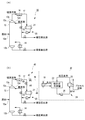
- FIGS. 2 (a) and 2 (b) are diagrams for explaining a method for remodeling a distillation facility according to an embodiment of the present invention. 2 (a) and 2 (b), the same or corresponding components as those in the distillation facility 10 shown in FIG.
- FIG. 2 (a) shows the distillation facility 30 before remodeling.
- the distillation equipment 30 shown in FIG. 2A is configured such that only the air-cooled cooler 16 provided on the line 17 connecting the distillation column 12 and the distillate tank 21 cools the top vapor. Therefore, in the distillation facility 30 before remodeling, the cooling capacity of the top vapor is affected by natural conditions. Especially in the summer, the cooling capacity is remarkably reduced, so that the condensation temperature of the top vapor of the tower rises, so that the operating pressure of the distillation tower 12 must be increased. As a result, since the reflux ratio must be increased, it is necessary to supply a large amount of energy to the reboiler 14, and the distillation facility 30 before the modification has a problem from the viewpoint of energy saving.
- FIG. 2 (b) shows the distillation equipment 40 after modification.
- the distillation facility 40 includes a water-cooled cooler 18, an absorption chiller 22 that supplies chilled water to the water-cooled cooler 18, and low-pressure steam that generates low-pressure steam using a process fluid and that is supplied to the absorption chiller 22.
- Modifications have been made to add additional components 42, including the device 24, to the distillation facility 30.
- An additional component 42 is added so that the output of the air-cooled cooler 16 and the input of the water-cooled cooler 18 are connected by a line 46, and the output of the water-cooled cooler 18 and the input of the distillate tank 21 are connected by a line 48. Is done. That is, the additional component 42 is added so that the water-cooled cooler 18 is located downstream of the air-cooled cooler 16.
- a first valve 47 is provided on the line 46.
- a line (referred to as a bypass line 44) that directly connects the air-cooled cooler 16 and the distillate tank 21 remains.
- a second valve 49 is provided on the bypass line 44.
- the water-cooled cooler 18 is provided in parallel with the bypass line 44 downstream of the air-cooled cooler 16 via lines 46 and 48.
- the distillation equipment 40 modified as shown in FIG. 2 (b), by controlling the open / close state of the first valve 47 and the second valve 49, the top vapor passing through the air-cooled cooler 16 and / or the condensation thereof.
- the first operating state in which the liquid enters the distillate tank 21 via the water-cooled cooler 18 and the overhead vapor and / or its condensate that has passed through the air-cooled cooler 16 are directly (ie, water-cooled cooled) via the bypass line 44.
- the second operating state entering the distillate tank 21 can be switched (without going through the vessel 18).
- the top vapor from the distillation tower 12 passes through the air-cooled cooler 16, the line 46, the water-cooled cooler 18, and the line 48 in this order, It enters the distillate tank 21 (first operation state).
- the top steam is condensed using the cold water produced by the absorption refrigerator 22.
- the top vapor from the distillation column 12 passes through the air-cooled cooler 16 and then directly (that is, water-cooled) via the bypass line 44. It enters the distillate tank 21 (without passing through the cooler 18) (second operation state). In this case, only the air-cooled cooler 16 condenses the tower top vapor.
- the switching between the first operating state and the second operating state may be performed based on the environmental conditions (for example, environmental temperature) of the plant in which the distillation facility is used. For example, when the environmental temperature is high in summer or in the daytime (for example, the environmental temperature of the plant is equal to or higher than a predetermined threshold), the air cooling cooler 16 alone cannot be expected to provide sufficient cooling capacity, so the first operation state is set. On the other hand, when the environmental temperature is low (for example, the environmental temperature of the plant is lower than a predetermined threshold value) in winter, for example, the air cooling cooler 16 alone can be expected to provide sufficient cooling capacity, so the second operation state is set.
- the environmental conditions for example, environmental temperature of the plant in which the distillation facility is used.
- the environmental temperature is high in summer or in the daytime (for example, the environmental temperature of the plant is equal to or higher than a predetermined threshold)
- the air cooling cooler 16 alone cannot be expected to provide sufficient cooling capacity, so the first operation state is set.
- the environmental temperature is low (for example
- both the first valve 47 and the second valve 49 are opened, and the top vapor and / or its condensate that has passed through the air-cooled cooler 16 enter the distillate tank 21 via the water-cooled cooler 18.
- a third operating state that enters the distillate tank 21 directly via the bypass line 44 may be set. In this case, since a plurality of condensing means (that is, the air-cooled cooler 16 and the water-cooled cooler 18) are prepared, even if a failure occurs in one condensing means, the operation of the distillation facility can be continued.
- the distillation facility 40 may include a control device for automatically switching the above-described operation state, that is, controlling the open / close state of the first valve 47 and the second valve 49.
- This control device may include, for example, a temperature sensor for measuring the environmental temperature and a control unit that controls opening and closing of the first valve 47 and the second valve 49 based on the output of the temperature sensor.
- the control unit may control the opening and closing of the first valve 47 and the second valve 49 based on the date and time when the distillation facility operates in addition to or instead of the output of the temperature sensor. That is, the opening and closing of the first valve 47 and the second valve 49 may be controlled according to the day or time zone in which the environmental temperature is expected to rise.
- the operation state may be switched by the operator of the distillation facility 40.
- the remodeling method according to the present embodiment by adding an additional component 42 to the existing distillation facility 30, as in the distillation facility 10 shown in FIG. It is possible to improve efficiency and facilitate maintenance / inspection of the distillation column 12. Further, since the air-cooled cooler 16 and the distillate tank 21 can be directly connected using the bypass line 44, it is easy to operate in the form of the original distillation equipment 30 after the modification.
- Fig. 3 shows the simulation results of distillation by distillation equipment before and after modification.
- a naphtha splitter is selected from a plurality of distillation columns with an operating pressure of 1.0 MPaG to 2.0 MPaG, which has a high energy-saving effect and does not require any significant remodeling of the packing.
- the equipment distillation was simulated.
- As the absorption refrigerator a water / lithium bromide type was selected.
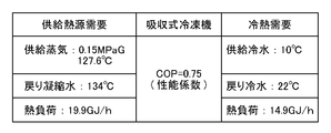
- FIG. 4 shows the setting conditions around the absorption refrigerator and the absorption refrigerator used in the simulation calculation.
- the performance coefficient (COP: Coefficient Of Performance) of the absorption refrigerator was set to 0.75.
- the pressure of the low-pressure steam supplied to the absorption refrigerator was set to 0.15 MPaG and the temperature was 127.6 ° C.
- emitted from the absorption refrigerator 22 was set to 134 degreeC.
- the temperature of the cold water supplied from the absorption chiller 22 to the water-cooled cooler 18 was 10 ° C., and the temperature of the cold water returning from the water-cooled cooler 18 to the absorption chiller 22 was 22 ° C.
- the low-pressure steam generator 24 generates low-pressure steam using heat obtained from the process fluid generated in the plant.
- the heat used for generating the low-pressure steam by the low-pressure steam generator 24 is not limited to the heat obtained from the process fluid, and may be obtained from exhaust heat that has not been effectively used in the conventional plant.
- the low-pressure steam generator 24 may generate low-pressure steam using, for example, exhaust heat generated when cooling the components of the distillation facility 10 (for example, the distillation column 12 or the like). Or when remodeling the existing distillation equipment, the low pressure steam generator 24 may generate low pressure steam using the exhaust heat from the existing cooler and air fin cooler in the plant. By these, the energy efficiency of the distillation installation 10 can be improved.
- the absorption chiller 22 produces cold water using low-pressure steam generated using heat generated in the plant.
- the absorption refrigerator 22 may manufacture cold water using hot water generated using heat generated in the plant.
- the temperature of the hot water may be 80 ° C. or higher, and preferably 90 ° C. or higher.
- the absorption refrigerator 22 can produce 7 ° C. cold water using 88 ° C. hot water. In both cases of using low-pressure steam and hot water, it can be said that the absorption refrigerator 22 is producing cold water using heat generated in the plant.
- the present invention can be used in a distillation facility for distilling raw materials in a plant.
Landscapes
- Chemical & Material Sciences (AREA)
- Engineering & Computer Science (AREA)
- Chemical Kinetics & Catalysis (AREA)
- Combustion & Propulsion (AREA)
- Physics & Mathematics (AREA)
- Mechanical Engineering (AREA)
- Thermal Sciences (AREA)
- General Engineering & Computer Science (AREA)
- Vaporization, Distillation, Condensation, Sublimation, And Cold Traps (AREA)
Abstract
プラント内に設けられる蒸留設備10は、供給された原料を蒸留する蒸留塔12と、プラント内で発生した熱を用いて低圧蒸気を発生させる低圧蒸気発生装置24と、低圧蒸気発生装置24で発生した低圧蒸気を用いて冷水を製造する吸収式冷凍機22と、蒸留塔12から流出する塔頂蒸気を吸収式冷凍機22で製造された冷水を用いて凝縮させる水冷冷却器18と、水冷冷却器18で凝縮した液体の一部を蒸留塔12に還流させる還流装置20とを備える。
Description
本発明は、プラントにおいて原料を蒸留する蒸留設備および蒸留方法並びに蒸留設備の改造方法に関する。
石油・石油化学等の産業プラントの蒸留設備では、蒸留塔の塔頂から流出する塔頂蒸気の凝縮方法として、空気を用いた空冷、冷却水を用いた水冷、それらを組み合わせた方法等が採用されている。蒸留塔の運転圧力を低下させる省エネルギーは広く知られており、省エネルギー実現のための課題の一つとなっている。
蒸留塔の運転圧力は、塔頂蒸気の凝縮温度で一様に決まり、凝縮温度が下がれば運転圧力も下がる。蒸留塔の運転圧力を下げると原料中の成分の比揮発度が大きくなり成分の分離が容易になる。従って、塔頂及び塔底の留出物(製品)の純度を所定の値に維持するための蒸留塔の内部還流が少なくできる。内部還流量は測定が困難であるが、外部還流量(以降、還流と呼ぶ)と相関があるので、一般的には還流比(=還流量/塔頂留出量)を塔頂及び塔底の留出物の純度の管理に用いている。塔頂留出量(製品)を一定とすると内部還流が少なくできれば、それを気化(再蒸発)するリボイラーの負荷も下げられる。従って、リボイラーに供給するエネルギーが減って省エネルギーを図ることができる。
塔頂蒸気の凝縮温度をより下げるためにはより高い冷却能力が必要となる。しかしながら、従来の空気や冷却水を用いた塔頂蒸気の凝縮方法の場合、冷却媒体である空気や冷却水の温度は自然条件に依存するため、常に設定した冷却能力を期待するのは難しく、従って塔頂蒸気の凝縮温度の維持には限界がある。特に夏期の気温上昇に伴い空気や冷却水の温度が高くなって冷却能力が著しく低下するため、塔頂蒸気の凝縮温度は高く設定せざるを得ない。従って、従来の空気や冷却水を用いた塔頂蒸気の凝縮方法では、蒸留塔の運転圧力を下げて省エネルギーを図ることは難しい。
本発明は、こうした状況を鑑みてなされたものであり、その目的は、省エネルギーを図ることのできる蒸留設備、蒸留方法および蒸留設備の改造方法を提供することにある。
上記課題を解決するために、本発明のある態様の蒸留設備は、プラント内に設けられる蒸留設備であって、供給された原料を蒸留する蒸留塔と、プラント内で発生した熱を用いて冷水を製造する冷凍機と、蒸留塔から流出する塔頂蒸気を製造された冷水を用いて凝縮させる水冷冷却器と、水冷冷却器で凝縮した液体の一部を蒸留塔に還流させる還流装置と、を備える。
プラント内で発生した熱を用いて低圧蒸気を発生させる低圧蒸気発生装置をさらに備え、冷凍機は、低圧蒸気発生装置で発生した低圧蒸気を用いて冷水を製造してもよい。
低圧蒸気発生装置で用いる熱は、プラント内で発生したプロセス流体から得られてもよい。
蒸留塔から流出する塔頂蒸気を空冷する空冷冷却器をさらに備えてもよい。
空冷冷却器は、水冷冷却器の上流に設けられてもよい。空冷冷却器と還流装置とを直接接続するためのバイパスラインをさらに備えてもよい。
冷凍機により製造される冷水は、7℃~12℃であってもよい。
本発明の別の態様は、プラント内での蒸留方法である。この方法は、蒸留塔を用いて供給された原料を蒸留する工程と、プラント内で発生した熱を用いて冷水を製造する工程と、蒸留塔から流出する塔頂蒸気を製造された冷水を用いて凝縮させる工程と、還流装置を用いて凝縮した液体の一部を蒸留塔に還流させる工程と、を備える。
冷水を用いて凝縮させる工程で用いる水冷冷却器の上流に、蒸留塔から流出する塔頂蒸気を空冷する空冷冷却器が設けられてもよい。空冷冷却器と還流装置とがバイパスラインを介して直接接続されてもよい。プラントの環境条件に基づいて、空冷冷却器を通過した塔頂蒸気および/またはその凝縮液が水冷冷却器を介して還流装置に入る第1動作状態と、空冷冷却器を通過した塔頂蒸気および/またはその凝縮液がバイパスラインを介して直接還流装置に入る第2動作状態とを切り替える工程をさらに備えてもよい。
本発明のさらに別の態様は、プラント内に設けられた蒸留塔から流出する塔頂蒸気を空冷冷却器で凝縮させる蒸留設備の改造方法である。この方法は、プラント内で発生した熱を用いて冷水を製造する冷凍機を設ける工程と、蒸留塔から流出する塔頂蒸気を冷凍機で製造された冷水を用いて凝縮させる水冷冷却器を設ける工程と、を備える。
蒸留設備は、凝縮した液体の一部を蒸留塔に還流させる還流装置を備え、水冷冷却器は、改造前の空冷冷却器と還流装置とを直接接続するラインを残したまま、空冷冷却器の下流にラインと並列に設けられてもよい。
なお、以上の構成要素の任意の組合せ、本発明の表現を方法、装置、システム、記録媒体、コンピュータプログラムなどの間で変換したものもまた、本発明の態様として有効である。
本発明によれば、省エネルギーを図ることのできる蒸留設備、蒸留方法および蒸留設備の改造方法を提供できる。
図1は、本発明の実施形態に係る蒸留設備10を説明するための図である。図1に示す蒸留設備10は、例えば石油精製プラントや石油化学プラント等の産業プラント内に設けられる。
図1に示すように、蒸留設備10は、蒸留塔12と、リボイラー14と、空冷冷却器16と、水冷冷却器18と、還流装置20と、吸収式冷凍機22と、低圧蒸気発生装置24とを備える。
蒸留塔12は、内部にトレイ等の構造物が設置されていて塔頂部12cから流下してくる液と塔底部12bから上昇してくる蒸気が熱交換と物質移動を繰り返して目的の純度の製品を得る機能を持つ。蒸留塔12の塔頂からは揮発性の高い成分に富む、塔底からは揮発性の低い成分に富む留出液が抜き出される。蒸留塔12は、その中段部に設けられた原料供給口12aから供給された原料を蒸留する。蒸留塔12内に供給された原料は、気液の2相からなり、液は蒸留塔12内を流下してきた液と合流して塔底部12bにおいてリボイラー14により加熱される。リボイラー14の加熱により、塔底部12bの塔底液の一部は蒸気とされ、塔頂部12cに向かって上昇する。蒸気とならない塔底液は塔底留出液となる。原料供給口12aで蒸気となった原料はリボイラー14からの蒸気と合流して蒸留塔12内を上昇する。また、蒸留塔12からの塔頂蒸気は凝縮されて還流装置を経て一部は塔頂留出液として抜き出され、残りは蒸留塔12の塔頂部12cに設けられた還流液供給口12dから還流液として供給される。
蒸気取出口12eから流出した塔頂蒸気は、ライン17を介して水冷冷却器18に入る。水冷冷却器18は、吸収式冷凍機22からの冷水を用いて塔頂蒸気を凝縮させる。水冷冷却器18により凝縮された液体は、還流装置20に送られる。
蒸留塔12と水冷冷却器18とを接続するライン17上に空冷冷却器16が設けられてもよい。すなわち、水冷冷却器18の上流に空冷冷却器16が設けられてもよい。空冷冷却器16は、蒸留塔12からの塔頂蒸気の少なくとも一部を凝縮するよう構成されてよい。この構成の場合、蒸留塔12からの塔頂蒸気およびその凝縮液は、空冷冷却器16、水冷冷却器18を順に通過した後、留出液タンク21に入る。
還流装置20は、水冷冷却器18で凝縮した液体の一部を蒸留塔12に還流させる。還流装置20は、留出液タンク21と、ポンプ23とを含む。水冷冷却器18で凝縮した液体は留出液タンク21に貯留される。留出液タンク21に貯留された液体は、ポンプ23により昇圧された後、その一部が留出液として取り出され、残りが還流液として還流液供給口12dを介して蒸留塔12内に還流される。
低圧蒸気発生装置24は、プラント内で発生したプロセス流体を用いて低圧蒸気を発生させる。低圧蒸気発生装置24は、ケトル型熱交換器25と、ポンプ26とを備える。ケトル型熱交換器25は、ボイラー給水(BFW:Boiler Feed Water)が供給される。ケトル型熱交換器25は、プロセス流体との熱交換によりこのBFWを加熱蒸発し、例えば0.15MPaGから0.20MPaGの低圧蒸気を発生させる。プロセス流体とは、プラント内で所定の生産を行うためのプロセス設備(例えば、反応器や熱交換器など)で生じた流体である。例えば石油プラントであれば、石油からガソリンを生成するためのプロセス設備、ガソリンからナフサを生成するためのプロセス設備、石油から灯油を生成するためのプロセス設備などである。
吸収式冷凍機22は、低圧蒸気発生装置24で発生した低圧蒸気を用いて冷水を製造する。本実施形態では、吸収式冷凍機22として水・臭化リチウム系のものを用いるが、吸収式冷凍機22はこれに限定されない。吸収式冷凍機22で製造される冷水の温度は、7℃~12℃であってよい。吸収式冷凍機22から排出された凝縮水は、ポンプ26を介して再びBFWとしてケトル型熱交換器25に供給される。
吸収式冷凍機22で製造された冷水は、水冷冷却器18に供給され、上述したように蒸留塔12からの塔頂蒸気を凝縮させるために用いられる。吸収式冷凍機22で製造された冷水は、自然条件に影響されない安定した高い冷却能力を提供できるため、塔頂蒸気の凝縮温度を下げて蒸留塔12の運転圧力を低下させることができる。蒸留塔12の運転圧力を下げることは、リボイラー14の負荷を下げることにつながる。すなわち、リボイラー14へ供給するエネルギーを低減できるため、省エネルギーを図ることができる。
また、本実施形態に係る蒸留設備10では、自然条件に影響されない安定した冷却能力を提供できるため、蒸留塔12に安定的に原料を供給することができる。すなわち、本実施形態に係る蒸留設備10によれば、収率の向上を図ることができる。
また、本実施形態に係る蒸留設備10では、吸収式冷凍機22に供給される低圧蒸気は、プラント内で発生したプロセス流体を用いて生成されている。低圧蒸気を発生させるために別途燃料を投入する必要がないため、プラント全体としてエネルギー効率を高めることができる。また、プロセス流体との熱交換で低圧蒸気を発生させているため、プロセス流体の温度を低下させることができる。これは、プロセス設備に使用するためにプロセス流体を冷却する必要がある場合には、プラント内でプロセス流体を冷却するための設備および負荷を軽減できることを意味するため、この観点からもプラント全体としてエネルギー効率を高めることができる。
また、蒸留塔の最高温度における運転圧力が10kg/cm2以上の場合は「高圧ガス」の適用を受け、その結果、保守・点検に多くの工数が必要となる。その点、本実施形態に係る蒸留設備10では、蒸留塔12の運転圧力を低下できることから、運転圧力が10kg/cm2未満に下がれば「高圧ガス」適用から外れ、その結果蒸留塔12の保守・点検が容易となる。また、新設の場合、蒸留塔12の運転圧力が低くなることにより、蒸留塔12の建設コスト(機器費)を下げることができる。
図2(a)および(b)は、本発明の実施形態に係る蒸留設備の改造方法を説明するための図である。図2(a)および(b)において、図1に示す蒸留設備10と同一又は対応する構成要素には同一の符号を付すとともに、重複する説明は適宜省略する。
図2(a)は、改造前の蒸留設備30を示す。図2(a)に示す蒸留設備30は、蒸留塔12と留出液タンク21を接続するライン17上に設けられた空冷冷却器16のみが塔頂蒸気の冷却を行うよう構成されている。従って、この改造前の蒸留設備30では、塔頂蒸気の冷却能力が自然条件に影響される。特に夏場には冷却能力が著しく低下するため、塔頂蒸気の凝縮温度が高くなるので蒸留塔12の運転圧力を上げなくてはならない。その結果、還流比を大きくしなければならないのでリボイラー14に多くのエネルギーを供給する必要が生じて、改造前の蒸留設備30は省エネルギーの観点から課題がある。
図2(b)は、改造後の蒸留設備40を示す。この蒸留設備40は、水冷冷却器18と、水冷冷却器18に冷水を供給する吸収式冷凍機22と、プロセス流体を用いて低圧蒸気を発生させ、吸収式冷凍機22に供給する低圧蒸気発生装置24と、を含む追加構成要素42を蒸留設備30に追加する改造がなされている。追加構成要素42は、空冷冷却器16の出力と水冷冷却器18の入力がライン46で接続され、水冷冷却器18の出力と留出液タンク21の入力がライン48で接続されるように追加される。すなわち、追加構成要素42は、空冷冷却器16の下流に水冷冷却器18が位置するように追加される。ライン46上には第1バルブ47が設けられる。図2(b)に示すように、空冷冷却器16と留出液タンク21とを直接接続するライン(バイパスライン44と呼ぶ)は残されている。バイパスライン44上には第2バルブ49が設けられる。図2(b)に示すように、水冷冷却器18は、ライン46,48を介して、空冷冷却器16の下流にバイパスライン44と並列に設けられる。
図2(b)のように改造された蒸留設備40においては、第1バルブ47と第2バルブ49の開閉状態を制御することで、空冷冷却器16を通過した塔頂蒸気および/またはその凝縮液が水冷冷却器18を介して留出液タンク21に入る第1動作状態と、空冷冷却器16を通過した塔頂蒸気および/またはその凝縮液がバイパスライン44を介して直接(すなわち水冷冷却器18を通らずに)留出液タンク21に入る第2動作状態とを切り替えることができる。
第1バルブ47を開状態且つ第2バルブ49を閉状態とした場合、蒸留塔12からの塔頂蒸気は、空冷冷却器16、ライン46、水冷冷却器18、ライン48を順に通過した後、留出液タンク21に入る(第1動作状態)。この場合、図1に示す蒸留設備10と同様に、空冷冷却器16に加えて、吸収式冷凍機22で製造された冷水を用いて塔頂蒸気の凝縮が行われる。その結果、塔頂蒸気の凝縮温度を下げて蒸留塔12の運転圧力を低下させることが可能となる。
一方、第1バルブ47を閉状態且つ第2バルブ49を開状態とした場合、蒸留塔12からの塔頂蒸気は、空冷冷却器16を通過した後、バイパスライン44を介して直接(すなわち水冷冷却器18を通らずに)留出液タンク21に入る(第2動作状態)。この場合、空冷冷却器16のみで塔頂蒸気の凝縮が行われる。
第1動作状態と第2動作状態の切替は、蒸留設備が用いられるプラントの環境条件(例えば環境温度等)に基づいて行われてもよい。例えば、夏場や昼間で環境温度が高い(例えばプラントの環境温度が所定の閾値以上である)場合、空冷冷却器16だけでは十分な冷却能力が期待できないため、第1動作状態に設定する。一方、例えば冬場等で環境温度が低い(例えばプラントの環境温度が所定の閾値未満である)場合、空冷冷却器16だけでも十分な冷却能力が期待できるため、第2動作状態に設定する。このような構成をとることにより、必要なときだけ水冷冷却器18や吸収式冷凍機22等の追加構成要素42を動作さればよくなるため、エネルギー効率を高めることができる。
さらに、第1バルブ47および第2バルブ49を共に開状態として、空冷冷却器16を通過した塔頂蒸気および/またはその凝縮液が、水冷冷却器18を介して留出液タンク21に入るとともに、バイパスライン44を介して直接留出液タンク21に入る第3動作状態を設定してもよい。この場合、複数の凝縮手段(すなわち空冷冷却器16および水冷冷却器18)を用意されるので、仮に一つの凝縮手段に故障が発生した場合でも、蒸留設備の運転を継続することができる。
蒸留設備40は、上記の動作状態の切り替え、すなわち第1バルブ47および第2バルブ49の開閉状態の制御を自動的に行うための制御装置を備えてもよい。この制御装置は、例えば環境温度を測定するための温度センサと、該温度センサの出力に基づいて第1バルブ47および第2バルブ49の開閉を制御する制御部を備えてもよい。
制御部は、温度センサの出力に加えてまたは代えて、蒸留設備が稼働する日時に基づいて第1バルブ47および第2バルブ49の開閉を制御してもよい。すなわち、環境温度が高くなることが想定される日や時間帯に応じて第1バルブ47および第2バルブ49の開閉を制御してもよい。
あるいは、上記動作状態の切り替えは、蒸留設備40の操作者によりなされてもよい。
本実施形態に係る改造方法によれば、既存の蒸留設備30に追加構成要素42を追加することで、図1に示す蒸留設備10と同様に、省エネルギー、収率の向上、プラント全体としてのエネルギー効率の向上、蒸留塔12の保守・点検の容易化などを図ることができる。また、バイパスライン44を用いて空冷冷却器16と留出液タンク21を直接接続することが可能なため、改造後に元々の蒸留設備30の形態で運用することも容易である。
図3は、改造前と改造後の蒸留設備による蒸留のシミュレーション結果を示す。ここでは、運転圧力が1.0MPaGから2.0MPaGの複数の蒸留塔の中から、省エネルギー効果が高く、充填物の大幅な改造を必要としないナフサスプリッターを選択し、改造前と改造後の蒸留設備による蒸留をシミュレーションした。吸収式冷凍機としては、水・臭化リチウム系のものを選択した。
図4は、シミュレーション計算に用いた吸収式冷凍機および吸収式冷凍機まわりの設定条件を示す。本シミュレーションでは、吸収式冷凍機の性能係数(COP:Coefficient Of Performance)を0.75とした。また、吸収式冷凍機に供給される低圧蒸気の圧力を0.15MPaG、温度を127.6℃とした。また、吸収式冷凍機22から排出される戻り凝縮水の温度を134℃とした。また、吸収式冷凍機22から水冷冷却器18に供給される冷水の温度を10℃とし、水冷冷却器18から吸収式冷凍機22に戻る冷水の温度を22℃とした。この冷水を製造するのに必要な熱負荷を14.9GJ/hとした。吸収式冷凍機のCOP=0.75であるため、吸収式冷凍機22が必要とする熱負荷は(14.9GJ/h)/0.75=19.9GJ/hとなる。
図3のシミュレーション結果から、改造前と比較して改造後は凝縮温度を35℃から25℃に低下でき、蒸留塔の運転圧力を1.10MPaGから0.70MPaGまで低下できていることが分かる。改造前に対する改造後の低圧化率は、(1.1MPaG-0.7MPaG)/1.1MPaG×100=36.4%である。その結果、リボイラーの熱負荷が20.1GJ/hから14.7GJ/hまで低下し、省エネルギー率=20.1GJ/h-14.7GJ/h)20.1GJ/h×100=26.9%を達成できている。
上述の実施形態では、低圧蒸気発生装置24は、プラント内で発生したプロセス流体から得られる熱を用いて低圧蒸気を発生させている。しかしながら、低圧蒸気発生装置24で低圧蒸気を発生させるために用いる熱は、プロセス流体から得られる熱に限定されず、従来プラント内で有効利用されていなかった排熱から得てもよい。低圧蒸気発生装置24は、例えば、蒸留設備10の構成要素(例えば蒸留塔12等)の冷却の際に生じる排熱等を利用して低圧蒸気を発生させてもよい。あるいは、既存の蒸留設備を改造する場合には、低圧蒸気発生装置24は、プラント内の既設のクーラー及びエアフィンクーラーからの排熱を用いて低圧蒸気を発生させてもよい。これらにより、蒸留設備10のエネルギー効率を高めることができる。
上述の実施形態では、吸収式冷凍機22は、プラント内で発生した熱を用いて発生された低圧蒸気を用いて冷水を製造している。しかしながら、吸収式冷凍機22は、プラント内で発生した熱を用いて発生された熱水を用いて冷水を製造してもよい。熱水の温度は、80℃以上であってよく、好ましくは90℃以上であってよい。例えば、吸収式冷凍機22は、88℃の熱水を用いて7℃の冷水を製造することができる。低圧蒸気を用いる場合と熱水を用いる場合ともに、吸収式冷凍機22はプラント内で発生した熱を用いて冷水を製造しているということができる。
以上、本発明を実施例をもとに説明した。この実施例は例示であり、それらの各構成要素や各処理プロセスの組合せにいろいろな変形例が可能なこと、またそうした変形例も本発明の範囲にあることは当業者に理解されるところである。
10、30、40 蒸留設備、 12 蒸留塔、 14 リボイラー、 16 空冷冷却器、 18 水冷冷却器、 20 還流装置、 21 留出液タンク、 22 吸収式冷凍機、 23 ポンプ、 24 低圧蒸気発生装置、 25 ケトル型熱交換器、 26 ポンプ、 42 追加構成要素、 44 バイパスライン、 47 第1バルブ、 49 第2バルブ。
本発明は、プラントにおいて原料を蒸留する蒸留設備に利用できる。
Claims (10)
- プラント内に設けられる蒸留設備であって、
供給された原料を蒸留する蒸留塔と、
前記プラント内で発生した熱を用いて冷水を製造する冷凍機と、
前記蒸留塔から流出する塔頂蒸気を製造された冷水を用いて凝縮させる水冷冷却器と、
前記水冷冷却器で凝縮した液体の一部を前記蒸留塔に還流させる還流装置と、
を備えることを特徴とする蒸留設備。 - 前記プラント内で発生した熱を用いて低圧蒸気を発生させる低圧蒸気発生装置をさらに備え、
前記冷凍機は、前記低圧蒸気発生装置で発生した低圧蒸気を用いて冷水を製造することを特徴とする請求項1に記載の蒸留設備。 - 前記低圧蒸気発生装置で用いる熱は、前記プラント内で発生したプロセス流体から得られることを特徴とする請求項2に記載の蒸留設備。
- 前記蒸留塔から流出する塔頂蒸気を空冷する空冷冷却器をさらに備えることを特徴とする請求項1から3のいずれかに記載の蒸留設備。
- 前記空冷冷却器は、前記水冷冷却器の上流に設けられており、
前記空冷冷却器と前記還流装置とを直接接続するためのバイパスラインをさらに備えることを特徴とする請求項4に記載の蒸留設備。 - 前記冷凍機により製造される冷水は、7℃~12℃であることを特徴とする請求項1から5のいずれかに記載の蒸留設備。
- プラント内での蒸留方法であって、
蒸留塔を用いて供給された原料を蒸留する工程と、
前記プラント内で発生した熱を用いて冷水を製造する工程と、
前記蒸留塔から流出する塔頂蒸気を製造された冷水を用いて凝縮させる工程と、
還流装置を用いて凝縮した液体の一部を前記蒸留塔に還流させる工程と、
を備えることを特徴とする蒸留方法。 - 前記冷水を用いて凝縮させる工程で用いる水冷冷却器の上流に、前記蒸留塔から流出する塔頂蒸気を空冷する空冷冷却器が設けられており、
前記空冷冷却器と前記還流装置とがバイパスラインを介して直接接続されており、
前記プラントの環境条件に基づいて、前記空冷冷却器を通過した塔頂蒸気および/またはその凝縮液が前記水冷冷却器を介して前記還流装置に入る第1動作状態と、前記空冷冷却器を通過した塔頂蒸気および/またはその凝縮液が前記バイパスラインを介して直接前記還流装置に入る第2動作状態とを切り替える工程をさらに備えることを特徴とする請求項7に記載の蒸留方法。 - プラント内に設けられた蒸留塔から流出する塔頂蒸気を空冷冷却器で凝縮させる蒸留設備の改造方法であって、
前記プラント内で発生した熱を用いて冷水を製造する冷凍機を設ける工程と、
前記蒸留塔から流出する塔頂蒸気を前記冷凍機で製造された冷水を用いて凝縮させる水冷冷却器を設ける工程と、
を備えることを特徴とする蒸留設備の改造方法。 - 前記蒸留設備は、凝縮した液体の一部を前記蒸留塔に還流させる還流装置を備え、
前記水冷冷却器は、改造前の前記空冷冷却器と前記還流装置とを直接接続するラインを残したまま、前記空冷冷却器の下流に前記ラインと並列に設けられることを特徴とする請求項9に記載の蒸留設備の改造方法。
Applications Claiming Priority (2)
| Application Number | Priority Date | Filing Date | Title |
|---|---|---|---|
| JP2014-141700 | 2014-07-09 | ||
| JP2014141700A JP6368179B2 (ja) | 2014-07-09 | 2014-07-09 | 蒸留設備および蒸留方法 |
Publications (1)
| Publication Number | Publication Date |
|---|---|
| WO2016006604A1 true WO2016006604A1 (ja) | 2016-01-14 |
Family
ID=55064234
Family Applications (1)
| Application Number | Title | Priority Date | Filing Date |
|---|---|---|---|
| PCT/JP2015/069518 Ceased WO2016006604A1 (ja) | 2014-07-09 | 2015-07-07 | 蒸留設備、蒸留方法および蒸留設備の改造方法 |
Country Status (2)
| Country | Link |
|---|---|
| JP (1) | JP6368179B2 (ja) |
| WO (1) | WO2016006604A1 (ja) |
Cited By (2)
| Publication number | Priority date | Publication date | Assignee | Title |
|---|---|---|---|---|
| CN109715258A (zh) * | 2016-09-07 | 2019-05-03 | 沙特基础全球技术有限公司 | 用于分离丙烯和丙烷的系统和方法 |
| CN115574621A (zh) * | 2022-08-31 | 2023-01-06 | 新疆中泰化学托克逊能化有限公司 | 一种转化系统热水节能装置 |
Citations (4)
| Publication number | Priority date | Publication date | Assignee | Title |
|---|---|---|---|---|
| JPS5971904U (ja) * | 1982-11-05 | 1984-05-16 | 三菱重工業株式会社 | 空冷コンデンサと水冷コンデンサとを有する蒸気タ−ビンの制御装置 |
| JPH0929001A (ja) * | 1995-07-17 | 1997-02-04 | Jgc Corp | 蒸留装置及び蒸留方法 |
| JP2000300902A (ja) * | 1999-04-23 | 2000-10-31 | Jgc Corp | 蒸留装置 |
| JP2007277182A (ja) * | 2006-04-07 | 2007-10-25 | Nippon Shokubai Co Ltd | 有機酸の製造方法 |
-
2014
- 2014-07-09 JP JP2014141700A patent/JP6368179B2/ja active Active
-
2015
- 2015-07-07 WO PCT/JP2015/069518 patent/WO2016006604A1/ja not_active Ceased
Patent Citations (4)
| Publication number | Priority date | Publication date | Assignee | Title |
|---|---|---|---|---|
| JPS5971904U (ja) * | 1982-11-05 | 1984-05-16 | 三菱重工業株式会社 | 空冷コンデンサと水冷コンデンサとを有する蒸気タ−ビンの制御装置 |
| JPH0929001A (ja) * | 1995-07-17 | 1997-02-04 | Jgc Corp | 蒸留装置及び蒸留方法 |
| JP2000300902A (ja) * | 1999-04-23 | 2000-10-31 | Jgc Corp | 蒸留装置 |
| JP2007277182A (ja) * | 2006-04-07 | 2007-10-25 | Nippon Shokubai Co Ltd | 有機酸の製造方法 |
Cited By (4)
| Publication number | Priority date | Publication date | Assignee | Title |
|---|---|---|---|---|
| CN109715258A (zh) * | 2016-09-07 | 2019-05-03 | 沙特基础全球技术有限公司 | 用于分离丙烯和丙烷的系统和方法 |
| JP2019529394A (ja) * | 2016-09-07 | 2019-10-17 | サビック グローバル テクノロジーズ ベスローテン フェンノートシャップ | プロピレンとプロパンとの分離のためのシステムおよび方法 |
| JP7019675B2 (ja) | 2016-09-07 | 2022-02-15 | サビック グローバル テクノロジーズ ベスローテン フェンノートシャップ | プロピレンとプロパンとの分離のためのシステムおよび方法 |
| CN115574621A (zh) * | 2022-08-31 | 2023-01-06 | 新疆中泰化学托克逊能化有限公司 | 一种转化系统热水节能装置 |
Also Published As
| Publication number | Publication date |
|---|---|
| JP2016016379A (ja) | 2016-02-01 |
| JP6368179B2 (ja) | 2018-08-01 |
Similar Documents
| Publication | Publication Date | Title |
|---|---|---|
| Waheed et al. | Performance enhancement of vapor recompression heat pump | |
| Kumar et al. | A novel multistage vapor recompression reactive distillation system with intermediate reboilers | |
| Jiménez-Arreola et al. | Direct vs indirect evaporation in Organic Rankine Cycle (ORC) systems: A comparison of the dynamic behavior for waste heat recovery of engine exhaust | |
| Vučković et al. | Advanced exergy analysis and exergoeconomic performance evaluation of thermal processes in an existing industrial plant | |
| Andersson et al. | Techno-economic analysis of excess heat driven post-combustion CCS at an oil refinery | |
| Mehdizadeh-Fard et al. | Improving energy efficiency in a complex natural gas refinery using combined pinch and advanced exergy analyses | |
| Long et al. | Review of retrofitting distillation columns using thermally coupled distillation sequences and dividing wall columns to improve energy efficiency | |
| Semkov et al. | Efficiency improvement through waste heat reduction | |
| De Paepe et al. | Water injection in a micro gas turbine–Assessment of the performance using a black box method | |
| Wang et al. | Optimal match between heat source and absorption refrigeration | |
| De Paepe et al. | Optimal waste heat recovery in micro gas turbine cycles through liquid water injection | |
| Reddy et al. | Improving energy efficiency of distillation using heat pump assisted columns | |
| CN106987264B (zh) | 一种凝析油分离装置及工艺方法 | |
| Wang et al. | Sustainable process design and multi-objective optimization of efficient and energy-saving separation of xylene isomers via extractive distillation based on double extractants | |
| Tahouni et al. | Debottlenecking of condensate stabilization unit in a gas refinery | |
| Wakabayashi et al. | Design and commercial operation of a discretely heat-integrated distillation column | |
| Pan et al. | Efficiency improvement of cogeneration system using statistical model | |
| Bahmani et al. | Simulation and optimization of an industrial gas condensate stabilization unit to modify LPG and NGL production with minimizing CO2 emission to the environment | |
| CN104383704B (zh) | 一种对气体分馏塔进口物料预热的梯级加热系统 | |
| Jahromi et al. | An extended energy saving method for modification of MTP process heat exchanger network | |
| JP6368179B2 (ja) | 蒸留設備および蒸留方法 | |
| Farhat et al. | A new methodology combining total site analysis with exergy analysis | |
| Van Duc Long et al. | Debottlenecking the retrofitted thermally coupled distillation sequence | |
| Gao et al. | Application of Three‐Vapor Recompression Heat‐Pump Concepts to a Dimethylformamide–Water Distillation Column for Energy Savings | |
| Liu et al. | A new retrofit approach to the absorption-stabilization process for improving energy efficiency in refineries |
Legal Events
| Date | Code | Title | Description |
|---|---|---|---|
| 121 | Ep: the epo has been informed by wipo that ep was designated in this application |
Ref document number: 15818559 Country of ref document: EP Kind code of ref document: A1 |
|
| NENP | Non-entry into the national phase |
Ref country code: DE |
|
| 122 | Ep: pct application non-entry in european phase |
Ref document number: 15818559 Country of ref document: EP Kind code of ref document: A1 |