WO2016009531A1 - 回転電機 - Google Patents
回転電機 Download PDFInfo
- Publication number
- WO2016009531A1 WO2016009531A1 PCT/JP2014/069072 JP2014069072W WO2016009531A1 WO 2016009531 A1 WO2016009531 A1 WO 2016009531A1 JP 2014069072 W JP2014069072 W JP 2014069072W WO 2016009531 A1 WO2016009531 A1 WO 2016009531A1
- Authority
- WO
- WIPO (PCT)
- Prior art keywords
- fins
- outer peripheral
- rotating electrical
- electrical machine
- fan
- Prior art date
- Legal status (The legal status is an assumption and is not a legal conclusion. Google has not performed a legal analysis and makes no representation as to the accuracy of the status listed.)
- Ceased
Links
Images


Classifications
-
- H—ELECTRICITY
- H02—GENERATION; CONVERSION OR DISTRIBUTION OF ELECTRIC POWER
- H02K—DYNAMO-ELECTRIC MACHINES
- H02K9/00—Arrangements for cooling or ventilating
- H02K9/02—Arrangements for cooling or ventilating by ambient air flowing through the machine
- H02K9/04—Arrangements for cooling or ventilating by ambient air flowing through the machine having means for generating a flow of cooling medium
-
- H—ELECTRICITY
- H02—GENERATION; CONVERSION OR DISTRIBUTION OF ELECTRIC POWER
- H02K—DYNAMO-ELECTRIC MACHINES
- H02K5/00—Casings; Enclosures; Supports
- H02K5/04—Casings or enclosures characterised by the shape, form or construction thereof
- H02K5/20—Casings or enclosures characterised by the shape, form or construction thereof with channels or ducts for flow of cooling medium
- H02K5/207—Casings or enclosures characterised by the shape, form or construction thereof with channels or ducts for flow of cooling medium with openings in the casing specially adapted for ambient air
-
- H—ELECTRICITY
- H02—GENERATION; CONVERSION OR DISTRIBUTION OF ELECTRIC POWER
- H02K—DYNAMO-ELECTRIC MACHINES
- H02K5/00—Casings; Enclosures; Supports
- H02K5/04—Casings or enclosures characterised by the shape, form or construction thereof
- H02K5/18—Casings or enclosures characterised by the shape, form or construction thereof with ribs or fins for improving heat transfer
Definitions
- the present invention relates to a rotating electrical machine and relates to a rotating electrical machine having a cooling structure for guiding cooling air to the outer surface of the rotating electrical machine.
- Rotating electrical machines generally tend to be larger in size when trying to achieve higher output and higher torque. Along with the increase in size of the rotating electrical machine, it is necessary to increase the size of the machine-side device in which the rotating electrical machine is incorporated, which causes problems such as restrictions on the installation space of the device and higher costs.
- ⁇ Cooling fans are often used to improve cooling efficiency against exhaust heat from the housing surface.
- patent document 1 as an example of the cooling structure using a cooling fan.
- a cooling fan is provided at the center position on the counter-output shaft side, a plurality of fins extending radially in the radial direction are provided on the outer surface of the end bracket, and the cooling air discharged from the cooling fan is rectified.
- a structure that improves the cooling efficiency by efficiently leading to the above is disclosed.
- the cooling fan provided at the center position on the counter-output shaft side is a self-excited fan
- the motor shaft rotates in both the clockwise and counterclockwise directions.
- the plurality of fins provided on the outer surface of the end bracket are radially arranged from the rotation axis so that the performance is the same. Therefore, since the cooling air discharged from the self-excited fan is a swirling flow, the cooling air collides with the fins on the outer surface of the end bracket, which has the same center and extends linearly from the inner peripheral side to the outer peripheral side. Becomes ventilation resistance, and the wind speed of the cooling air decreases.
- every other plurality of fins provided on the outer surface of the end bracket are arranged with respect to the fins on the outer peripheral surface of the housing to be connected. Therefore, the end of the fin on the outer peripheral surface of the housing that is not connected to the fin on the outer surface of the end bracket collides with the cooling air from the cooling fan to generate turbulent flow and the cooling air interferes with each other. Cannot be efficiently guided to the motor body side.
- An object of the present invention is to cool a rotating electrical machine more efficiently.
- the present invention includes a plurality of means for solving the above-mentioned problems.
- a housing having a plurality of cooling fins extending from the end portion on the counter-output shaft side toward the output shaft side on the outer peripheral surface.
- An end bracket having a plurality of cooling fins provided on the outer surface of the housing on the side opposite to the output shaft, a cooling fan disposed at a central position on the side opposite to the output shaft, and cooling air from the fan
- the number of fins on the outer peripheral surface of the housing is the same as the number of fins on the outer surface of the end bracket.
- the plurality of fins on the outer surface of the end bracket are arranged on the inner peripheral side at an angle along the direction of the cooling air from the fan that is a swirling flow, and on the outer peripheral side, the end cross section is And anti-output shaft side end section of the fins of the housing outer peripheral surface, a rotating electrical machine to reduce opposing the gap without or gap.
- a housing provided with a plurality of cooling fins on the outer peripheral surface extending from the end portion on the counter-output shaft side toward the output shaft side, and an end bracket provided on the counter-output shaft side of the housing
- a cooling fan disposed at the center position on the counter-output shaft side, a fan cover that is inclined so that cooling air from the fan is directed toward the housing side, and has a plurality of fins on the inner surface
- the number of fins on the inner surface of the fan cover is the same as the number of fins on the outer peripheral surface of the housing, and the plurality of fins on the inner surface of the fan cover are swiveled on the inner peripheral side.
- the fin is disposed at an angle along the direction of the cooling air from the fan, and on the outer peripheral side, the end section of the fin is the same as the end section of the fin on the outer peripheral surface of the housing. Or a rotating electrical machine to reduce opposing the gap.
- a housing provided with a plurality of cooling fins on the outer peripheral surface extending from the end portion on the counter-output shaft side toward the output shaft side, and a cooling provided on the counter-output shaft side of the housing
- An end bracket having a plurality of fins on the outer surface, a cooling fan disposed at a central position on the counter-output shaft side, and an inclination so that cooling air from the fan is directed to the housing side.
- a rotary electric machine having a fan cover having a plurality of fins on the inner surface, the number of fins on the outer peripheral surface of the housing, the number of fins on the inner surface of the fan cover, and the number of fins on the outer surface of the end bracket
- the plurality of fins on the inner surface of the fan cover are arranged at an angle along the direction of the cooling air from the fan that is a swirling flow on the inner peripheral side, and the fan cover
- the outer peripheral end cross section of the fin on the surface and the inner peripheral end cross section of the fin on the outer surface of the end bracket face each other without a gap or with a small gap, and on the outer peripheral side, the fin on the outer surface of the end bracket
- This is a rotating electrical machine in which the cross section on the outer peripheral side of the housing and the cross section on the counter output shaft side of the fin on the outer peripheral surface of the housing face each other without a gap or with a small gap.
- the cooling efficiency of the rotating electrical machine is improved.
- FIG. 1 and FIG. 2 show a rotating electrical machine of Example 1 to which the present invention is applied.
- FIG. 1 is a view of the surface portion of the end bracket 3 on the counter-output shaft side as viewed from the counter-output shaft side.
- FIG. 2 shows a side view of the rotating electrical machine of the first embodiment.
- the rotating electrical machine of the first embodiment includes a housing 5 and a rotating shaft 7 that is an output shaft, and a plurality of fins 6 extending in parallel with the output shaft are provided on the outer peripheral surface of the housing 5.
- the fins 6 are provided radially from the outer peripheral surface of the housing in the radial direction, for example.
- the plurality of fins may extend spirally with respect to the output shaft.
- An end bracket 3 is attached to the side opposite to the output shaft of the housing 5, and a radial inclination is provided on the outer surface of the end bracket 3 toward the outer peripheral side of the housing 5 with the axial center as the center. That is, the outer surface of the end racket 3 has a substantially truncated cone shape.
- the shape of the outer surface of the end bracket 3 may be a polygonal frustum, a hemispherical shape, or a funnel shape, and is not limited to a truncated cone.
- a plurality of fins 4 extending from the inner peripheral side to the outer peripheral side are arranged on the outer surface of the end bracket 3.
- the number of fins 4 is the same as the number of fins 6 provided on the outer peripheral surface of the housing 5.
- the fins 4 are provided such that the outer peripheral side end portion side is inclined in any of the left and right rotational directions with respect to the central end portion of the end bracket 3.
- the inclining direction coincides with the turning direction of the turning air blown from the fan described later (in the case of this example, the outer peripheral side end is inclined in the clockwise direction).
- the outermost end portion of the fin 4 is formed so as to be parallel to the radiation extension line from the center of the end bracket 3.
- the fin 4 is configured such that the outer end side cross section of the parallel portion and the end bracket side end cross section of the fin 6 on the outer periphery of the housing 5 face each other without a gap or with a small gap, and the cross sections at both ends are close to each other. Or configured to contact. That is, a flow path that is continuous from the inner peripheral side of the end bracket 3 toward the outer periphery of the housing 5 is formed between the pair of fins 4 and 6 whose end sections are opposed to each other.
- the fin width (thickness) in the vicinity of the end cross section facing at least the fin 6 of the fin 4 is preferably equal to or greater than the fin width (thickness) of the end cross section of the fin 6. More preferred. This is to eliminate the elements (steps and gaps) that become the resistance of the cooling air 8 at the opposing portions of the end section.
- a separately excited fan 1 that generates cooling air 8 is supported by the fan cover 2 and arranged.
- the self-excited fan is driven by a motor or the like different from the rotating electric machine, unlike a self-excited fan that generates cooling air by rotating around the rotary shaft 7 with the center of the fan connected to the rotary shaft 7. I am a fan.
- the cooling air generated by the separately excited fan 1 is a swirling flow (in this example, it is a right swirling with respect to the end bracket 3). Note that the present invention is not limited to the separately excited fan, and may be a self-excited fan, and preferably generates a cooling air that forms a swirling flow with respect to the end bracket 3.
- the fan cover 2 has a substantially concave inner peripheral shape covering the outer surface of the end bracket 3 and the entire vicinity of the fins 4 and 6 near the opposite output shaft side. Further, a part of the inner periphery of the fan cover 2 is provided with an inclination formed of an annular linear portion, and cooling from the separately excited fan 1 installed at the central portion of the fan cover 2 in the extension line direction of the rotating shaft 7. The wind 8 is guided to the outer peripheral surface of the housing 5.
- the metallic fan cover 2 such as iron or aluminum is exemplified, but a resin or the like may be used.
- the corners of the fin 4 on the outer peripheral side and in the opposite output shaft direction have a shape cut out substantially in parallel with the inclination of the inner periphery of the fan cover 2, and the fan cover 2 is When installed, the top of the notch and the inclined portion of the fan cover 2 are configured to be close to or in contact with each other.
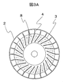
- FIGS. 3A and 3B are views of the surface portion of the end bracket 3 as viewed from the side opposite to the output shaft
- FIG. 3B is a view of the rotating electrical machine as viewed from the side.
- the cooling air 8 discharged from the fan 1 in a swirling manner flows along the fins 4 on the outer surface of the end bracket 3 arranged along the air direction of the cooling air 8 on the inner peripheral side. Further, the cooling air 8 is guided to the outer peripheral side of the end bracket 3 by the inclination applied to the fan cover 2 and the inclination of the outer surface of the end bracket 3 to which the cooling air 8 is blown.
- the cooling air 8 guided to the outer peripheral side of the end bracket 3 smoothly passes through the gap between the fan cover 2 and the outer peripheral side of the end bracket 3 and the outer peripheral surface of the housing 4 and is discharged to the housing 5 side.
- the cooling air 8 blown to the end bracket 3 is a swirling air. Since the outer periphery side of the fin 4 is inclined toward the turning direction of the swirl wind, the linear component of the cooling air that collides with the fin 4 proceeds to the outer periphery side without being attenuated by the inclination of the fin 4. That is, it proceeds to the outer peripheral side while maintaining the wind pressure. The amount of cooling air traveling on the surface of the end bracket 3 and the surface of the housing 5 becomes large, and the cooling efficiency is improved.
- the flow path secured by both has a large air volume. This prevents the cooling air from diffusing and generating turbulent flow, and allows the cooling air 8 to flow to the outer periphery of the housing 5 more efficiently.
- the fins 4 are inclined toward the outer peripheral side, the fin length is longer than that in the case where the fins 4 are formed in a radial straight line from the center of the end bracket 3, and the heat dissipation elements (fins 4 and end 4) of the end bracket 3 are increased. There is also an effect that the outer surface of the bracket 3 is increased.
- the cooling efficiency by the fins 4 and 6 it is possible to expect power saving and downsizing of the separately excited fan 1. That is, in the rotating electrical machine of this embodiment, the amount of air flowing through the surfaces of the end bracket 3 and the housing 4 is increased as compared with the rotating electrical machine to which the configuration of the present embodiment is not applied. Therefore, the size of the separately excited fan 1 can be reduced.
- the shape of the end bracket 3 is a substantially frustum shape to improve the flow efficiency of the cooling air.
- the rotating electrical machine is a servo motor
- the end on the side opposite to the output shaft is provided.
- an encoder for measuring the number of rotations or the like is built in the bracket 3 side.
- a configuration in which the inside of the frustum-shaped end bracket 3 is a space with a built-in encoder is also possible.
- a self-excited fan cannot be installed on the non-output shaft side, and a cooling structure using a separately-excited fan may be used. Applying the configuration of the present embodiment to the servo motor can improve the cooling efficiency while maintaining the installation configuration and space of the encoder, and can be said to be one of the particularly preferable applications.
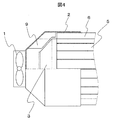
- FIG. 4 shows the rotating electrical machine of Example 2 to which the present invention is applied.
- the fins 4 are provided on the outer surface of the end bracket 3 on the side opposite to the output shaft.
- the fan cover 2 to which the separately excited fan 1 is attached is used instead of the outer surface of the end bracket 3.
- a plurality of fins 9 are provided on the inner surface.
- the fin 9 is formed from the inner peripheral side of the inner surface of the fan cover 2 to a position corresponding to the fin 6 on the outer peripheral surface of the housing 5.
- the number of fins 9 is the same as the number of fins 6 provided on the outer peripheral surface of the housing 5.
- the fins 9 provided on the inner surface of the fan cover 2 are arranged on the inner peripheral side at an angle along the direction of the cooling air 8 that is swirled from the separately excited fan 1.
- the fin 9 has a linear shape from the inner peripheral side to the outer peripheral side, is refracted at a certain point, for example, the position of the outer peripheral surface of the housing 5, and is provided linearly toward the outer peripheral side.
- the outermost end cross-section of the fin 9 and the end cross-section of the fin 6 are configured to face each other without a gap or with a small gap so as to be close to or in contact with each other. Yes.
- the same effects as those of the first embodiment can be obtained, and the collision between the cooling air 8 and the fins 9 can be mitigated.
- the turbulent flow generated by colliding with the end of 6 can be suppressed, the cooling air 8 can be smoothly guided to the housing side, and the cooling efficiency of the rotating electrical machine can be improved.
- the fins 9 can be provided from the vicinity of the separately-excited fan 1, and the rectifying effect of the cooling air is improved.
- the fin cover 2 of the second embodiment is not required to have a function as a heat dissipation element, so that the fan cover 2 can be easily manufactured at a low cost using a resin or the like. While improving the cooling efficiency of the rotating electrical machine, it is also possible to expect manufacturing cost and weight saving merit. Further, by providing the fan cover 2 with fins 9 and attaching the separately excited fan 1 for integration, it is possible to expect the merit of manufacturing and assembling the rotating electrical machine.
- FIG. 5 shows a rotating electrical machine of Example 3 to which the present invention is applied.
- a plurality of fins 4 are provided on the outer surface of the end bracket 3 on the counter-output shaft side, and a plurality of fins are formed on the inner surface of the fan cover 2 to which the separately excited fan 1 located at the center of the counter-output shaft is attached. 9 is provided.
- the number of fins 4 and fins 9 is the same as the number of fins 6 provided on the outer peripheral surface of the housing 5.
- the fins 9 provided on the inner surface of the fan cover 2 are arranged on the inner peripheral side at an angle along the direction of the cooling air 8 that is swirled from the separately excited fan 1.
- the end cross section of the fin 9 formed on the inner surface of the fan cover 2 and the end cross section of the fin 4 formed on the outer surface of the end bracket 3 have no gap or a gap so that they are close to or in contact with each other. It is configured to face less.
- the fin body composed of the fin 9 and the fin 4 has a linear shape from the inner peripheral side to the outer peripheral side, refracts at a certain point, for example, the position of the outer peripheral surface of the housing 5, and is linear toward the outer peripheral side. Is formed.
- the end cross section of each fin 4 is opposed to the end cross section of the fin 6 on the outer peripheral surface of the corresponding housing so as to be close to or in contact with each other with little or no gap. Has been.
- the same effect as in the first or second embodiment is obtained, and the collision between the cooling air 8 and the fin 9 on the inner surface of the fan cover 2 or the fin 4 on the outer surface of the end bracket 3 is achieved. Can be relaxed. Further, it is possible to suppress the occurrence of turbulent flow in the connecting portion between the fin 9 and the fin 4 and the connecting portion between the fin 4 and the fin 6, and to smoothly guide the cooling air 8 to the housing side. Cooling efficiency can be improved.
- the fins 9 can be provided from the vicinity of the separately excited fan 1 as in the second embodiment, and the rectifying effect of the cooling air is improved.
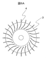
- Example 4 is different from Example 1 or Example 2 in the shape of the fin 4 or the fin 9.
- 6A is a view showing a modification of the fin shape applied to the outer surface of the end bracket as viewed from the side opposite to the output shaft
- FIG. 6B is a modification of the fin shape applied to the inner surface of the fan cover as viewed from the output shaft.
- the shape of the fins 4 on the outer surface of the end bracket 3 is arranged along the swirl direction of the cooling air on the inner peripheral side, and is smoothly curved from the inner peripheral side toward the outer peripheral side. For example, it is formed linearly from the position corresponding to the outer periphery of the housing toward the outer peripheral side of the end bracket 3.
- the fin 9 on the inner surface of the fan cover 2 is arranged along the turning direction of the cooling air on the inner peripheral side, and is smoothly curved from the inner peripheral side toward the outer peripheral side. For example, it is formed linearly from the position corresponding to the outer periphery of the housing toward the outer peripheral side of the end bracket 3.
- the fins 4 on the outer surface of the end bracket 3 or the fins 9 on the inner surface of the fan cover 2 are smoothly curved from the inner peripheral side toward the outer peripheral side.
- the cooling efficiency of the rotating electrical machine can be improved.
Landscapes
- Engineering & Computer Science (AREA)
- Power Engineering (AREA)
- Physics & Mathematics (AREA)
- Thermal Sciences (AREA)
- Motor Or Generator Cooling System (AREA)
- Motor Or Generator Frames (AREA)
Abstract
Description
本発明は、上記課題を解決する手段を複数含んでいるが、その一例を挙げるならば、反出力軸側端部から出力軸側に向かって延伸する冷却用のフィンを外周面に複数備えるハウジングと、前記ハウジングの反出力軸側に設けられる冷却用のフィンを、外表面に複数備えるエンドブラケットと、反出力軸側の中心位置に配置される冷却用のファンと、前記ファンからの冷却風が前記ハウジング側へ向かうように傾斜が施されたファンカバーと、を有する回転電機であって、前記ハウジング外周面のフィンの数と、前記エンドブラケット外表面のフィンの数とは、同数であり、前記エンドブラケットの外表面の複数のフィンは、内周側では、旋回流である前記ファンからの冷却風の風向に沿う角度で配置され、また、外周側では、端部断面が、前記ハウジング外周面のフィンの反出力軸側端部断面と、間隙無く或いは間隙を少なく対向する回転電機である。
更に、ファンカバー2にフィン9を設け、他励ファン1を取り付けて一体化することにより、回転電機の製造、組み立て面のメリットも期待できる。
2 ファンカバー
3 エンドブラケット
4 エンドブラケット外表面のフィン
5 ハウジング
6 ハウジング外周面のフィン
7 回転軸(出力軸)
8 他励ファンからの冷却風
9 ファンカバー内面のフィン
Claims (18)
- 反出力軸側端部から出力軸側に向かって延伸する冷却用のフィンを外周面に複数備えるハウジングと、
前記ハウジングの反出力軸側に設けられる冷却用のフィンを、外表面に複数備えるエンドブラケットと、
反出力軸側の中心位置に配置される冷却用のファンと、
前記ファンからの冷却風が前記ハウジング側へ向かうように傾斜が施されたファンカバーと、
を有する回転電機であって、
前記ハウジング外周面のフィンの数と、前記エンドブラケット外表面のフィンの数とは、同数であり、
前記エンドブラケットの外表面の複数のフィンは、内周側では、旋回流である前記ファンからの冷却風の風向に沿う角度で配置され、また、外周部では、端部断面が、前記ハウジング外周面のフィンの反出力軸側端部断面と、間隙無く或いは間隙を少なく対向する回転電機。 - 請求項1に記載の回転電機であって、
前記エンドブラケット外表面のフィンが、内周側から外周側へ向かい直線形状をなし、ある点で屈折し、外周側へ向かい直線状に形成された回転電機。 - 請求項1に記載の回転電機であって、
前記エンドブラケット外表面のフィンが、内周側から外周側に向かうにつれて滑らかに湾曲し、ある点より外周側へ向かい直線状に形成された回転電機。 - 請求項1に記載の回転電機であって、
前記エンドブラケットの外表面の複数のフィンの外周側端部近傍の厚みと、前記ハウジング外周面の複数のフィンの反出力軸側近傍の厚みとが、略同一である回転電機。 - 請求項1に記載の回転電機であって、
前記冷却用のファンが、他励ファンである回転電機。 - 請求項5に記載の回転電機であって、
前記他励ファンが、前記ファンカバーに取り付けられている回転電機。 - 反出力軸側端部から出力軸側に向かって延伸する冷却用のフィンを外周面に複数備えるハウジングと、
前記ハウジングの反出力軸側に設けられるエンドブラケットと、
反出力軸側の中心位置に配置される冷却用のファンと、
前記ファンからの冷却風が前記ハウジング側へ向かうように傾斜が施され、また内面に複数のフィンを備えたファンカバーと、
を有する回転電機であって、
前記ファンカバー内面のフィンの数と前記ハウジング外周面のフィンの数とは、同数であり、
前記ファンカバーの内面の複数のフィンは、内周側では、旋回流である前記ファンからの冷却風の風向に沿う角度で配置され、また、外周側では、フィンの端部断面が、前記ハウジング外周面のフィンの反出力軸側端部断面と、間隙無く或いは間隙を少なく対向する回転電機。 - 請求項7に記載の回転電機であって、
前記ファンカバー内面のフィンが、内周側から外周側へ向かい直線形状をなし、ある点で屈折し、外周側へ向かい直線状に形成された回転電機。 - 請求項7に記載の回転電機であって、
前記ファンカバーの内面のフィンが、内周側から外周側に向かうにつれて滑らかに湾曲し、ある点より外周側へ向かい直線状に形成された回転電機。 - 請求項7に記載の回転電機であって、
前記ファンカバー内面のフィンの外周側端部近傍の厚みと、前記ハウジング外周面の複数のフィンの反出力軸側近傍の厚みとが、略同一である回転電機。 - 請求項7に記載の回転電機であって、
前記冷却用のファンが、他励ファンである回転電機。 - 請求項11に記載の回転電機であって、
前記他励ファンが、前記ファンカバーに取り付けられている回転電機。 - 反出力軸側端部から出力軸側に向かって延伸する冷却用のフィンを外周面に複数備えるハウジングと、
前記ハウジングの反出力軸側に設けられる、冷却用のフィンを外表面に複数備えるエンドブラケットと、
反出力軸側の中心位置に配置される冷却用のファンと、
前記ファンからの冷却風が前記ハウジング側へ向かうように傾斜が施され、また内面に複数のフィンを備えたファンカバーと、
を有する回転電機であって、
前記ハウジング外周面のフィンの数と、前記ファンカバーの内面のフィンの数と、前記エンドブラケット外表面のフィンの数とは、同数であり、
前記ファンカバー内面の複数のフィンが、内周側では、旋回流である前記ファンからの冷却風の風向に沿う角度で配置され、
前記ファンカバー内面のフィンの外周側端部断面と、前記エンドブラケット外表面のフィンの内周側端部断面とが、間隙無く或いは間隙を少なく対向し、
また、外周側において、前記エンドブラケット外表面のフィンの外周側端部断面と、前記ハウジング外周面のフィンの反出力軸側端部断面とが、間隙無く或いは間隙を少なく対向する回転電機。 - 請求項13に記載の回転電機であって、
前記ファンカバーの内面のフィンと、前記エンドブラケット外表面のフィンとで構成されるフィン体が、内周側から外周側へ向かい直線形状をなし、ある点で屈折し、外周側へ向かい直線状に形成された回転電機。 - 請求項13に記載の回転電機であって、
前記ファンカバーの内面のフィンと、前記エンドブラケット外表面のフィンとで構成されるフィン体が、内周側から外周側に向かうにつれて滑らかに湾曲し、ある点より外周側へ向かい直線状に形成された回転電機。 - 請求項13に記載の回転電機であって、
前記ファンカバー内面のフィンの外周側端部近傍の厚みと、前記エンドブラケット外表面の複数のフィンの内周側端部近傍の厚みとが、略同一であり、
前記エンドブラケット外表面の複数のフィンの外周側端部近傍の厚みと、前記ハウジング外周面の複数のフィンの反出力軸側端部近傍の厚みとが、略同一である回転電機。 - 請求項13に記載の回転電機であって、
前記冷却用のファンが、他励ファンである回転電機。 - 請求項17に記載の回転電機であって、
前記他励ファンが、前記ファンカバーに取り付けられている回転電機。
Priority Applications (4)
| Application Number | Priority Date | Filing Date | Title |
|---|---|---|---|
| PCT/JP2014/069072 WO2016009531A1 (ja) | 2014-07-17 | 2014-07-17 | 回転電機 |
| CN201480079659.9A CN106416014B (zh) | 2014-07-17 | 2014-07-17 | 旋转电机 |
| JP2016534047A JP6259087B2 (ja) | 2014-07-17 | 2014-07-17 | 回転電機 |
| EP14897774.7A EP3171492B1 (en) | 2014-07-17 | 2014-07-17 | Rotating electric machine |
Applications Claiming Priority (1)
| Application Number | Priority Date | Filing Date | Title |
|---|---|---|---|
| PCT/JP2014/069072 WO2016009531A1 (ja) | 2014-07-17 | 2014-07-17 | 回転電機 |
Publications (1)
| Publication Number | Publication Date |
|---|---|
| WO2016009531A1 true WO2016009531A1 (ja) | 2016-01-21 |
Family
ID=55078048
Family Applications (1)
| Application Number | Title | Priority Date | Filing Date |
|---|---|---|---|
| PCT/JP2014/069072 Ceased WO2016009531A1 (ja) | 2014-07-17 | 2014-07-17 | 回転電機 |
Country Status (4)
| Country | Link |
|---|---|
| EP (1) | EP3171492B1 (ja) |
| JP (1) | JP6259087B2 (ja) |
| CN (1) | CN106416014B (ja) |
| WO (1) | WO2016009531A1 (ja) |
Cited By (6)
| Publication number | Priority date | Publication date | Assignee | Title |
|---|---|---|---|---|
| WO2019189442A1 (ja) * | 2018-03-28 | 2019-10-03 | 日本電産株式会社 | 回転翼装置 |
| JP2020502964A (ja) * | 2016-12-15 | 2020-01-23 | ボストン ダイナミクス,インコーポレイテッド | 脚付きロボット用のモーターおよびコントローラ一体化 |
| WO2020170824A1 (ja) * | 2019-02-19 | 2020-08-27 | 株式会社 マキタ | 電動作業機 |
| JP2022189307A (ja) * | 2021-06-11 | 2022-12-22 | 株式会社荏原製作所 | 冷却ファン、電動機組立体 |
| WO2023243116A1 (ja) * | 2022-06-13 | 2023-12-21 | 株式会社日立産機システム | 回転電機 |
| JP2024512777A (ja) * | 2021-04-01 | 2024-03-19 | カーエスベー ソシエタス ヨーロピア ウント コンパニー コマンディート ゲゼルシャフト アウフ アクチェン | 冷却装置を備えた電気モータ |
Families Citing this family (2)
| Publication number | Priority date | Publication date | Assignee | Title |
|---|---|---|---|---|
| CN113007828A (zh) * | 2021-04-12 | 2021-06-22 | 山东豪事达智能家居有限公司 | 一种高效降温循环扇及其工作方法 |
| CN118432349B (zh) * | 2024-07-05 | 2024-09-06 | 广东兆力电机集团有限公司 | 一种散热结构、电机机壳及电机 |
Citations (5)
| Publication number | Priority date | Publication date | Assignee | Title |
|---|---|---|---|---|
| JPS62107546U (ja) * | 1985-12-25 | 1987-07-09 | ||
| JPH089594A (ja) * | 1994-06-24 | 1996-01-12 | Toshiba Corp | 全閉外扇形回転電機 |
| JPH09252563A (ja) * | 1996-03-14 | 1997-09-22 | Toshiba Corp | 制御装置一体型モータ |
| JP2003218295A (ja) * | 2002-01-21 | 2003-07-31 | Nippon Densan Corp | ヒートシンク及びこれを備える冷却装置 |
| JP2007174824A (ja) * | 2005-12-22 | 2007-07-05 | Nissan Motor Co Ltd | 電動機固定子の冷却法 |
Family Cites Families (4)
| Publication number | Priority date | Publication date | Assignee | Title |
|---|---|---|---|---|
| JPH07245915A (ja) * | 1994-03-01 | 1995-09-19 | Hitachi Ltd | 回転電気機械 |
| JP2008091644A (ja) * | 2006-10-02 | 2008-04-17 | Nippon Densan Corp | ヒートシンク及びヒートシンク冷却装置 |
| DE202008000225U1 (de) * | 2008-01-07 | 2008-03-13 | Hanning Elektro-Werke Gmbh & Co. Kg | Elektromotor |
| CN101764467A (zh) * | 2008-12-09 | 2010-06-30 | 江苏海狮机械集团有限公司 | 全自动工业洗衣机中电动机的风冷却装置 |
-
2014
- 2014-07-17 WO PCT/JP2014/069072 patent/WO2016009531A1/ja not_active Ceased
- 2014-07-17 JP JP2016534047A patent/JP6259087B2/ja not_active Expired - Fee Related
- 2014-07-17 CN CN201480079659.9A patent/CN106416014B/zh not_active Expired - Fee Related
- 2014-07-17 EP EP14897774.7A patent/EP3171492B1/en active Active
Patent Citations (5)
| Publication number | Priority date | Publication date | Assignee | Title |
|---|---|---|---|---|
| JPS62107546U (ja) * | 1985-12-25 | 1987-07-09 | ||
| JPH089594A (ja) * | 1994-06-24 | 1996-01-12 | Toshiba Corp | 全閉外扇形回転電機 |
| JPH09252563A (ja) * | 1996-03-14 | 1997-09-22 | Toshiba Corp | 制御装置一体型モータ |
| JP2003218295A (ja) * | 2002-01-21 | 2003-07-31 | Nippon Densan Corp | ヒートシンク及びこれを備える冷却装置 |
| JP2007174824A (ja) * | 2005-12-22 | 2007-07-05 | Nissan Motor Co Ltd | 電動機固定子の冷却法 |
Non-Patent Citations (1)
| Title |
|---|
| See also references of EP3171492A4 * |
Cited By (9)
| Publication number | Priority date | Publication date | Assignee | Title |
|---|---|---|---|---|
| JP2020502964A (ja) * | 2016-12-15 | 2020-01-23 | ボストン ダイナミクス,インコーポレイテッド | 脚付きロボット用のモーターおよびコントローラ一体化 |
| JP2021182862A (ja) * | 2016-12-15 | 2021-11-25 | ボストン ダイナミクス,インコーポレイテッド | 脚付きロボット用のモーターおよびコントローラ一体化 |
| WO2019189442A1 (ja) * | 2018-03-28 | 2019-10-03 | 日本電産株式会社 | 回転翼装置 |
| WO2020170824A1 (ja) * | 2019-02-19 | 2020-08-27 | 株式会社 マキタ | 電動作業機 |
| JP2024512777A (ja) * | 2021-04-01 | 2024-03-19 | カーエスベー ソシエタス ヨーロピア ウント コンパニー コマンディート ゲゼルシャフト アウフ アクチェン | 冷却装置を備えた電気モータ |
| JP2022189307A (ja) * | 2021-06-11 | 2022-12-22 | 株式会社荏原製作所 | 冷却ファン、電動機組立体 |
| WO2023243116A1 (ja) * | 2022-06-13 | 2023-12-21 | 株式会社日立産機システム | 回転電機 |
| JP2023181851A (ja) * | 2022-06-13 | 2023-12-25 | 株式会社日立産機システム | 回転電機 |
| JP7660545B2 (ja) | 2022-06-13 | 2025-04-11 | 株式会社日立産機システム | 回転電機 |
Also Published As
| Publication number | Publication date |
|---|---|
| JP6259087B2 (ja) | 2018-01-10 |
| EP3171492A4 (en) | 2018-04-04 |
| EP3171492B1 (en) | 2021-05-12 |
| CN106416014A (zh) | 2017-02-15 |
| JPWO2016009531A1 (ja) | 2017-04-27 |
| EP3171492A1 (en) | 2017-05-24 |
| CN106416014B (zh) | 2019-04-02 |
Similar Documents
| Publication | Publication Date | Title |
|---|---|---|
| JP6259087B2 (ja) | 回転電機 | |
| US9621010B2 (en) | Rotating electrical machine | |
| US8593022B2 (en) | Electric motor with heat dissipation structure | |
| US9473001B2 (en) | Brushless motor fan with stator insulator having ventilation recesses and grooves | |
| JP6376981B2 (ja) | 回転装置 | |
| CN101981352B (zh) | 适配器、减速器和驱动装置 | |
| CN101517865A (zh) | 具有内冷转子的电机 | |
| CN105027398A (zh) | 旋转电机 | |
| TWM595926U (zh) | 散熱框架組件 | |
| JP6504754B6 (ja) | 電動送風機およびそれを用いた電気掃除機 | |
| US20180076693A1 (en) | Electric motor having improved cooling | |
| JP2016116272A (ja) | 回転電機及びファンカバー | |
| JP2015092800A (ja) | 電力供給ユニット一体型回転電機 | |
| JP5156223B2 (ja) | 回転電機 | |
| JP6213397B2 (ja) | 回転電機 | |
| JP6084561B2 (ja) | 回転電機 | |
| JP6694804B2 (ja) | 外転型回転電機 | |
| JP6208652B2 (ja) | ファンを有する電動機の冷却機構 | |
| JP5517714B2 (ja) | 回転電機 | |
| KR20150048383A (ko) | 산업용 전동기 | |
| JP7504320B1 (ja) | モータ | |
| JP7329721B1 (ja) | 回転電機 | |
| JP6775715B1 (ja) | ロータおよび回転電機 | |
| US10784735B2 (en) | Rotor and generator including the same | |
| KR200237059Y1 (ko) | 전동기의 냉각구조 |
Legal Events
| Date | Code | Title | Description |
|---|---|---|---|
| 121 | Ep: the epo has been informed by wipo that ep was designated in this application |
Ref document number: 14897774 Country of ref document: EP Kind code of ref document: A1 |
|
| ENP | Entry into the national phase |
Ref document number: 2016534047 Country of ref document: JP Kind code of ref document: A |
|
| REEP | Request for entry into the european phase |
Ref document number: 2014897774 Country of ref document: EP |
|
| WWE | Wipo information: entry into national phase |
Ref document number: 2014897774 Country of ref document: EP |
|
| NENP | Non-entry into the national phase |
Ref country code: DE |