WO2016009726A1 - 航空機用作動油配管の洗浄装置及び洗浄方法 - Google Patents
航空機用作動油配管の洗浄装置及び洗浄方法 Download PDFInfo
- Publication number
- WO2016009726A1 WO2016009726A1 PCT/JP2015/065515 JP2015065515W WO2016009726A1 WO 2016009726 A1 WO2016009726 A1 WO 2016009726A1 JP 2015065515 W JP2015065515 W JP 2015065515W WO 2016009726 A1 WO2016009726 A1 WO 2016009726A1
- Authority
- WO
- WIPO (PCT)
- Prior art keywords
- hydraulic oil
- valve
- pipe
- cleaning
- cleaning agent
- Prior art date
- Legal status (The legal status is an assumption and is not a legal conclusion. Google has not performed a legal analysis and makes no representation as to the accuracy of the status listed.)
- Ceased
Links
Images


Classifications
-
- B—PERFORMING OPERATIONS; TRANSPORTING
- B08—CLEANING
- B08B—CLEANING IN GENERAL; PREVENTION OF FOULING IN GENERAL
- B08B9/00—Cleaning hollow articles by methods or apparatus specially adapted thereto
- B08B9/02—Cleaning pipes or tubes or systems of pipes or tubes
- B08B9/027—Cleaning the internal surfaces; Removal of blockages
- B08B9/032—Cleaning the internal surfaces; Removal of blockages by the mechanical action of a moving fluid, e.g. by flushing
- B08B9/0321—Cleaning the internal surfaces; Removal of blockages by the mechanical action of a moving fluid, e.g. by flushing using pressurised, pulsating or purging fluid
- B08B9/0323—Arrangements specially designed for simultaneous and parallel cleaning of a plurality of conduits
-
- B—PERFORMING OPERATIONS; TRANSPORTING
- B08—CLEANING
- B08B—CLEANING IN GENERAL; PREVENTION OF FOULING IN GENERAL
- B08B9/00—Cleaning hollow articles by methods or apparatus specially adapted thereto
- B08B9/02—Cleaning pipes or tubes or systems of pipes or tubes
- B08B9/027—Cleaning the internal surfaces; Removal of blockages
- B08B9/032—Cleaning the internal surfaces; Removal of blockages by the mechanical action of a moving fluid, e.g. by flushing
- B08B9/0321—Cleaning the internal surfaces; Removal of blockages by the mechanical action of a moving fluid, e.g. by flushing using pressurised, pulsating or purging fluid
- B08B9/0325—Control mechanisms therefor
-
- B—PERFORMING OPERATIONS; TRANSPORTING
- B64—AIRCRAFT; AVIATION; COSMONAUTICS
- B64F—GROUND OR AIRCRAFT-CARRIER-DECK INSTALLATIONS SPECIALLY ADAPTED FOR USE IN CONNECTION WITH AIRCRAFT; DESIGNING, MANUFACTURING, ASSEMBLING, CLEANING, MAINTAINING OR REPAIRING AIRCRAFT, NOT OTHERWISE PROVIDED FOR; HANDLING, TRANSPORTING, TESTING OR INSPECTING AIRCRAFT COMPONENTS, NOT OTHERWISE PROVIDED FOR
- B64F5/00—Designing, manufacturing, assembling, cleaning, maintaining or repairing aircraft, not otherwise provided for; Handling, transporting, testing or inspecting aircraft components, not otherwise provided for
- B64F5/30—Cleaning aircraft
-
- B—PERFORMING OPERATIONS; TRANSPORTING
- B08—CLEANING
- B08B—CLEANING IN GENERAL; PREVENTION OF FOULING IN GENERAL
- B08B2209/00—Details of machines or methods for cleaning hollow articles
- B08B2209/02—Details of apparatuses or methods for cleaning pipes or tubes
- B08B2209/027—Details of apparatuses or methods for cleaning pipes or tubes for cleaning the internal surfaces
- B08B2209/032—Details of apparatuses or methods for cleaning pipes or tubes for cleaning the internal surfaces by the mechanical action of a moving fluid
Definitions
- the present invention relates to a cleaning device and a cleaning method for hydraulic oil pipes arranged in an aircraft body.
- Patent Document 1 discloses a single lever type faucet disposed at a terminal part of a water supply pipe and a hot water supply pipe, in a water supply pipe and a pipe between the hot water supply pipe and the water tap, An invention in which a piston for avoiding the occurrence of water hammer action is arranged is disclosed.
- the water hammer prevention device described in Patent Document 1 is disposed in the vicinity of a water supply pipe and a water supply pipe faucet through which fluid flows in one direction. And generation
- Patent Document 2 discloses a method for releasing a water channel in a fluid passage through which a fluid flows in one direction.
- the vibration Pr is detected by a vibration sensor arranged upstream of the actuator-actuated valve, and the control for the vibration detection signal Pr to be substantially zero is performed.
- the vibration sensor is disposed in the vicinity of the upstream side of the actuator-actuated valve.
- Patent Document 3 discloses a water hammer suppression device that suppresses water hammer generated in a main pipe line (a flow path through which fluid flows in one direction) for an inline turbine in a hydroelectric power plant.
- the water hammer suppression device described in Patent Literature 3 includes a bypass conduit and a rupture disk that bypass the inline turbine near the inline turbine.
- the water hammer suppression device described in Patent Document 3 is a drastic suppression of the amount of inflow into the inline turbine as the inline turbine generator is disconnected from the system due to an accident or the like. As a result, the water hammer generated as a result is suppressed and the occurrence of water hammer is confirmed after the fact.
- auxiliary wings, rudder and elevator In addition to the main control surfaces such as auxiliary wings, rudder and elevator, secondary control surfaces such as flaps, spoilers, slats, and air brakes, retractable legs, brakes, steering, reverse injection
- moving parts such as devices.
- An actuator is connected to each of these movable parts.
- the actuator In the configuration in which the actuator is driven using hydraulic pressure, the actuator is driven and the movable part is moved by controlling the hydraulic pressure supplied to the hydraulic oil piping of the supply flow path and the return flow path connected to the actuator.
- a hydraulic oil pipe is connected to a hydraulic oil tank, a hydraulic pump, and the like.
- Aircraft generally have a plurality of independent hydraulic systems from the viewpoint of safety. Accordingly, the number of hydraulic oil pipes arranged in the wing and the fuselage is inevitably increased.
- the hydraulic oil piping is composed of many parts such as elbows, joints, branching parts, and fittings when passing through the bulkhead.Many man-hours are required to clean the hydraulic oil piping during manufacturing and overhauling. It is necessary.
- a cleaning device is connected to each hydraulic oil piping system, and the cleaning operation in the hydraulic oil piping, the cleaning confirmation operation, and the switching operation of the hydraulic oil piping to be cleaned are repeated in the hydraulic oil piping. Was cleaning.
- the distance from the supply end of the hydraulic oil piping to the equipment end is often as long as 10 to 40 m. For this reason, the switching operation of the hydraulic oil piping at the time of the cleaning operation requires many people and man-hours.
- An object of the present invention is to provide a cleaning device and a cleaning method for cleaning a supply flow path and a return flow path of hydraulic oil pipes arranged in an aircraft body in a shorter time.
- the cleaning device of the present invention is a cleaning device that simultaneously cleans the first hydraulic oil piping and the second hydraulic oil piping of the aircraft.
- the cleaning device is connected to a cleaning agent supply flow path connected to a supply end of the first hydraulic oil pipe included in the first hydraulic system, and a supply end of the second hydraulic oil pipe included in the second hydraulic system.
- a cleaning agent circulation device having a cleaning agent return flow path.
- the cleaning device is disposed between the connection end of the first hydraulic oil pipe and the connection end of the second hydraulic oil pipe, and fluidly connects the first hydraulic oil pipe and the second hydraulic oil pipe.
- the connecting pipe opening / closing valve controls the flow rate of the cleaning agent flowing through the connecting pipe with valve based on an instruction from the control unit.
- the cleaning device of the present invention it is possible to clean the supply flow path and the return flow path of the hydraulic oil piping arranged in the aircraft body in a shorter time.
- FIG. 1 is a diagram schematically illustrating an example of a hydraulic circuit of a cleaning agent circulation device in a cleaning device.
- FIG. 2 is a diagram schematically illustrating the connection between the hydraulic circuit of the two hydraulic oil pipings on the aircraft side to be cleaned, the connecting pipe with a valve, and the connecting pipe on-off valve.
- FIG. 3 is a first half portion of a flowchart for explaining a pipe cleaning method using the cleaning apparatus.
- FIG. 4 is the latter half of the flowchart for explaining the pipe cleaning method using the cleaning apparatus.
- FIG. 5 is a chart for explaining the opening / closing operation (Left) of the connecting pipe opening / closing valve.
- FIG. 6 is a diagram schematically illustrating an example of a hydraulic circuit in which a bypass channel and a bypass valve are arranged in a cleaning agent circulation device in the cleaning device.
- FIG. 7 is a diagram schematically illustrating the connection between the hydraulic circuit of the two hydraulic oil pipes on the aircraft side to be cleaned, the connecting pipe with a valve, and the connecting pipe on-off valve.
- FIG. 8 is a timing chart for explaining the opening / closing timing of the bypass valve and the connecting pipe opening / closing valve in the cleaning process.
- FIG. 9 is a timing chart for explaining the opening / closing operation of the servo-type bypass valve and the connecting pipe opening / closing valve in the cleaning process.
- FIG. 10 is a diagram schematically illustrating a connection example of the hydraulic circuit of the two hydraulic oil pipings on the aircraft side to be cleaned, the connecting pipe with a valve, and the connecting pipe on-off valve.
- FIG. 11 is a chart for explaining the opening / closing operation (Right) of the connecting pipe opening / closing valve.
- FIG. 12 is a diagram schematically illustrating a connection example of the hydraulic circuit of the four hydraulic oil pipes on the aircraft side to be cleaned, the connecting pipe with a valve, the branch connecting pipe, and the connecting pipe on-off valve. .
- FIG. 13 is a diagram illustrating a cleaning agent circulation apparatus having two supply channels and one return channel.
- FIG. 14 schematically illustrates a connection example of a hydraulic circuit of five hydraulic oil pipes having an odd number of supply ends to be cleaned, a connection pipe with a valve, a branch connection pipe, and a connection pipe on-off valve.
- FIG. 15 is a chart for explaining an opening / closing operation (Center) of the connecting pipe opening / closing valve for cleaning the hydraulic oil pipe having an odd number of supply ends.
- FIG. 16 is a timing chart for controlling the supply valve, the bypass valve, and the connecting pipe opening / closing valve 24 based on the opening / closing operation shown in FIG. FIG.
- FIG. 17 shows a hydraulic circuit of three systems of hydraulic oil pipes including a sixth hydraulic oil pipe having equipment ends at both ends, a connection pipe with a valve, a connection pipe with a multi-branch valve, a connection pipe on-off valve, It is a figure which illustrates roughly the example of a connection with a pipe
- FIG. 18 is a diagram illustrating a cleaning agent circulation apparatus having four supply channels and three return channels.
- FIG. 19 shows a hydraulic circuit of five hydraulic oil pipes including a sixth hydraulic oil pipe having an equipment end at both ends, a connection pipe with a valve, a connection pipe with a multi-branch valve, a branch connection pipe, and a connection pipe It is a figure which illustrates roughly the example of a connection with an on-off valve and a connection pipe.
- FIG. 20 is a chart for explaining the opening / closing operation of the connection pipe opening / closing valve when cleaning the Left hydraulic oil pipe (for example, the hydraulic oil pipe arranged on the left wing).
- FIG. 21 is a connection example of a hydraulic circuit of five hydraulic oil pipes having an odd number of supply ends to be cleaned, a connection pipe with a valve, a branch connection pipe, a connection pipe on-off valve, and a connection pipe.
- FIG. FIG. 22 is a chart for explaining the opening / closing operation of the connection pipe opening / closing valve when cleaning the center hydraulic oil pipe (for example, the hydraulic oil pipe arranged on the body).
- FIG. 23 is a chart for explaining the opening / closing operation of the connection pipe opening / closing valve when cleaning the Right hydraulic oil pipe (for example, the hydraulic oil pipe arranged on the right wing).
- FIG. 1 is a diagram schematically illustrating an example of a hydraulic circuit of a cleaning agent circulation device 12 in the cleaning device 10.
- FIG. 2 shows a hydraulic circuit of two systems of hydraulic oil pipes composed of a first hydraulic oil pipe (91, 91A) and a second hydraulic oil pipe (92, 92A) on the aircraft side to be cleaned, It is a figure which illustrates roughly the example of a connection with the washing
- FIG. 3 and 4 are flowcharts for explaining a pipe cleaning method using the cleaning apparatus 10.
- FIG. 5 is a chart for explaining the opening / closing operation (Left) of the connecting pipe opening / closing valve 24.
- FIG. 1 shows a pump unit 30 and a cleaning agent circulation device 12 included in the cleaning device 10.
- the pump unit 30 pumps a cleaning agent having a predetermined pressure and a predetermined flow rate through the supply flow path 31P. Moreover, the pump part 30 collect
- the cleaning agent for example, a phosphate ester synthetic oil or the like can be used.
- the cleaning agent circulation device 12 includes a supply flow path 31, a return flow path 32, and a control unit 14.
- the cleaning agent circulation device 12 includes an input unit 15, a display unit 16, a storage unit 17, an output unit 18, a valve 38, a valve 39, a purge agent 40, a purge valve 41, a purge check valve 45, a purge as necessary.
- a check valve 46, a pressure gauge 47, a flow site 48 (flow light pipe), a thermometer 49, a filter 50, a filter valve 52, a flow meter 56, and a sampler 57 can be provided.
- the supply flow path 31 is a flow path that connects the supply flow path 31P of the pump unit 30 and the first hydraulic oil pipe 91 of the aircraft to supply the cleaning agent to the first hydraulic oil pipe 91.
- the return flow path 32 is a flow path that connects the return flow path 32P of the pump unit 30 and the second hydraulic oil pipe 92 of the aircraft and returns the cleaning agent from the second hydraulic oil pipe 92.
- the valve 38 is disposed in the supply flow path 31P between the pump unit 30 and the cleaning agent circulation device 12 and the return flow path 32P between the pump unit 30 and the cleaning agent circulation device 12, respectively.
- the valve 38 is closed.
- the pump unit 30 and the cleaning agent circulation device 12 are connected to clean the hydraulic oil piping, the valve 38 is opened so that the cleaning agent can be circulated.
- a valve that is manually opened and closed, an electromagnetic valve, or the like can be used as the valve 38.
- the valve 39 includes a supply flow path 31S between the cleaning agent circulation device 12 and the hydraulic oil piping (for example, the first hydraulic oil piping 91), and the cleaning agent circulation device 12 and the hydraulic oil piping (for example, the second hydraulic oil piping). 92) in the return channel 32S.
- the valve 39 is closed.
- the valve 39 is opened so that the cleaning agent can be circulated.
- a valve that is manually opened and closed, an electromagnetic valve, or the like can be used as the valve 39.
- the purge agent 40 is a fluid that is pumped into the hydraulic oil piping in the process of removing the cleaning agent after the cleaning of the hydraulic oil piping is completed.
- An inert gas such as nitrogen gas can be used as the purge agent 40.
- the purge valve 41 is a valve used to supply the purge agent 40 to the hydraulic oil piping via the supply flow path 31 or to shut off the supply.
- the purge valve 41 is normally closed and opened in a purging process for removing the cleaning agent.
- the purge check valve 45 is a check valve that prevents the cleaning agent from flowing into the supply valve 31 on the purge valve 41 side during cleaning or the like.
- the purge check valve 46 is a check valve that prevents the purge agent 40 from flowing into the pressure gauge 47 or the pump unit 30 side of the supply flow path 31 in the purging process or the like.
- the pressure gauge 47 is a device that is arranged in the supply flow path 31 and measures the supply pressure of the cleaning agent at the time of cleaning.
- the flow site 48 is an ophthalmic tube that is arranged in the return flow path 32 and inspects the flow of the cleaning agent.
- the thermometer 49 is a device that is disposed in the return flow path 32 and measures the temperature of the cleaning agent.
- the filter 50 is a device that is disposed in the return flow path 32 and prevents dust (contamination) present in the hydraulic oil pipe from being collected and flowing into the pump unit 30 in the cleaning process.
- the filter valve 52 is arranged in parallel with the filter 50 in the return flow path 32.
- the filter valve 52 is normally closed, and the cleaning agent circulated through the hydraulic oil pipe is passed through the filter 50.
- the filter valve 52 is opened, and the purge agent 40 is allowed to flow downstream without passing through the filter 50.
- the flow meter 56 is a device that is disposed in the return flow path 32 and measures the flow rate of the cleaning agent during cleaning.
- the sampler 57 is disposed in the return flow path 32, measures the amount of dust (contamination) contained in the cleaning agent returned during cleaning, and determines the end of cleaning, or the dust inspection device. This is a connector for connecting the inspection device and the return flow path 32.
- the control unit 14 acquires measurement values of various measuring devices such as a pressure gauge 47, a thermometer 49, a flow meter 56, and a sampler 57, and the periphery of the input unit 15, the display unit 16, the storage unit 17, the output unit 18, and the like. Send and receive information to and from the device. Moreover, the control part 14 controls the purge valve 41, the filter valve 52, and the connection pipe on-off valve 24 mentioned later with reference to FIG. The control unit 14 can automate the cleaning of the hydraulic oil piping by inputting information and commands from each peripheral device according to a pre-programmed order and outputting the information and commands to each peripheral device.
- various measuring devices such as a pressure gauge 47, a thermometer 49, a flow meter 56, and a sampler 57, and the periphery of the input unit 15, the display unit 16, the storage unit 17, the output unit 18, and the like. Send and receive information to and from the device. Moreover, the control part 14 controls the purge valve 41, the filter valve 52, and the connection pipe
- the input unit 15 includes a switch, a button, a keyboard, and the like. An operator inputs an instruction for starting automatic cleaning, determining various cleaning conditions, an emergency stop, and the like, and inputs the input instruction to the control unit 14. Output device.
- the display unit 16 includes a display device such as a display panel and a display lamp. Based on instructions from the control unit 14, the display unit 16 displays measurement values of various measuring devices, displays processes during automatic cleaning, and various types during automatic cleaning. Displays status and other displays.
- the storage unit 17 stores measurement values of various measuring devices, progress information of automatic cleaning, storage of various statuses during automatic cleaning, storage of programs related to automatic measurement, and the like.
- the output unit 18 outputs a control command such as opening / closing to the connecting pipe on / off valve 24 based on an instruction from the control unit 14. Further, the output unit 18 outputs the measurement values of various measuring devices, the output of process information at the time of automatic cleaning, and the output of various statuses to the computer PC connected to the outside based on an instruction from the control unit 14. It can be carried out.
- first hydraulic oil pipes 91, 91 ⁇ / b> A, 91 ⁇ / b> B and second hydraulic oil pipes 92, 92 ⁇ / b> A, 92 ⁇ / b> B are mounted on the aircraft side (for example, main wing).
- the connecting pipe 22 with a valve and the connecting pipe opening / closing valve 24 of the cleaning device 10 are connected to the equipment end 97 communicating with the first hydraulic oil pipes 91A and 91B and the second hydraulic oil pipes 92A and 92B.
- the equipment end 97 is a connection end on the equipment side to which an arbitrary device or member is connected when the aircraft is used.
- a supply end 95 is formed at one end of the first hydraulic oil pipe 91 (for example, the side connected to the fuselage in the main wing).
- a T-branch portion 96 is formed in the middle of the first hydraulic oil pipe 91 disposed inside the aircraft.
- Equipment ends (connection ends) 97 are provided at the ends of the first hydraulic oil pipe 91A and the first hydraulic oil pipe 91B, respectively.
- the supply end 95 is a connection part connected to the fuselage side of an aircraft, for example. Further, the equipment end 97 is a connection portion connected to the actuator side of the control device.
- a supply end 95 is formed at one end of the second hydraulic oil pipe 92 (for example, the side connected to the fuselage in the main wing).
- a T branch portion 96 is formed in the middle of the second hydraulic oil pipe 92 disposed inside the aircraft, and the second hydraulic oil pipe 92A (first branch portion) and the second hydraulic oil pipe 92B (second Branches to the branch part).
- Equipment ends (connection ends) 97 are provided at the ends of the second hydraulic oil pipe 92A and the second hydraulic oil pipe 92B, respectively.
- the equipment end 97 is, for example, a connection portion connected to the actuator side of the control device.
- the connecting pipe 22 with the valve is disposed between the first hydraulic oil pipe 91 ⁇ / b> A (first branch part) and the second hydraulic oil pipe 92 ⁇ / b> A (first branch part).
- the first hydraulic oil pipe 91 ⁇ / b> A and the second hydraulic oil pipe 92 ⁇ / b> A are fluidly connected via the valved connecting pipe 22.
- another connecting pipe 22 with a valve is arranged between the first hydraulic oil pipe 91B (second branch part) and the second hydraulic oil pipe 92B (second branch part).
- the first hydraulic oil pipe 91 ⁇ / b> B and the second hydraulic oil pipe 92 ⁇ / b> B are fluidly connected via the other valved connecting pipe 22.
- step S10 Connect the connecting pipe to the equipment end of the hydraulic oil piping of the aircraft”, the operator connects the equipment end 97 of the first hydraulic oil pipe 91A and the equipment end 97 of the second hydraulic oil pipe 92A.
- the connecting pipe 22 with valve is connected between the two.
- the connecting pipe 22 with the valve is connected between the equipment end 97 of the first hydraulic oil pipe 91B and the equipment end 97 of the second hydraulic oil pipe 92B.
- the connecting pipe 22 with valve is provided with a connecting pipe on / off valve 24 for controlling the passage and stop of the cleaning agent.
- step S12 “Connect the pipe to the pump unit, the cleaning agent circulation device, and the hydraulic oil piping of the aircraft.”
- the operator sets the supply flow path 31P (pipe) of the pump unit 30 shown in FIG. Connected to the supply flow path 31 of the cleaning agent circulation device 12, and the return flow path 32 ⁇ / b> P (pipe) is connected to the return flow path 32 of the cleaning agent circulation device 12.
- the supply flow path 31S is connected to the supply flow path 31 of the cleaning agent circulation device 12, and the supply flow path 31S is connected to the supply end 95 (port AO) of the first hydraulic oil pipe 91 of the aircraft shown in FIG.
- the return flow path 32S is connected to the return flow path 32 of the cleaning agent circulation device 12, and the return flow path 32S is connected to the supply end 95 (port AN) of the second hydraulic oil pipe 92 of the aircraft shown in FIG. .
- step S12 “Connect the control line of the connecting pipe on / off valve to the cleaning agent circulation device”, the operator is distant from the control lines 24C that transmit the control signal to the connecting pipe on / off valve 24. It connects with the output part 18 of the cleaning agent circulation apparatus 12 arrange
- step S14 “filling with cleaning agent”
- the pump unit 30 is started and the closed valve 38 and valve 39 are opened to set the state in which the cleaning agent can be circulated.
- the operator operates the input unit 15 and the like to instruct the control unit 14 to start pipe cleaning.
- the control unit 14 In the next step S16 “n-th pipe cleaning”, the control unit 14 outputs a control command for supplying a predetermined pressure and flow rate to the pump unit 30. Then, the control unit 14 instructs the opening / closing operation of the connection pipe opening / closing valve 24 via the output unit 18. As a result, the time elapse timer starts measuring time, and the cleaning device 10 starts cleaning.
- the control unit 14 acquires measurement values of various measuring devices such as a pressure gauge 47, a thermometer 49, a flow meter 56, a sampler 57, and the like as necessary, and at predetermined times (for example, at predetermined time intervals). The data is stored in the storage unit 17. The measured value can be displayed on the display unit 16 or output to the computer PC connected to the outside via the output unit 18.
- the first hydraulic oil pipes 91 and 91A and the second hydraulic oil pipes 92 and 92A shown in FIG. 5 are cleaned.
- the first hydraulic oil pipes 91 and 91B and the second hydraulic oil pipes 92 and 92B shown in FIG. 2 are cleaned.
- all of the first hydraulic oil pipes 91, 91A, 91B and the second hydraulic oil pipes 92, 92A, 92B shown in FIG. 2 are cleaned.
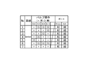
- the cleaning oil temperature is 100 ° F. and the minimum flow rate is 8. It is possible to determine 0 GPM (Gallon Per Minute), the cleaning agent pressure up to 900 PSI (Pound-force per Square Inch), and the amount of dust (contamination level) below a predetermined value (cleaner than CLASS 3). Further, in the third pipe cleaning step (No. 3), since the parallel portion exists in the pipe, the minimum value of the flow rate of the cleaning agent can be increased to 10.0 GPM.
- next step S18 “predetermined time elapse?”
- the control unit 14 performs a process of waiting for the count value of the time elapse timer to elapse a predetermined waiting time T1 (for example, 5 minutes).
- a predetermined waiting time T1 for example, 5 minutes.
- next step S20 “Contamination inspection OK?”
- the control unit 14 determines that the amount of dust (contamination level) contained in the cleaning agent measured by the sampler 57 is not more than a predetermined value (for example, from CLASS3).
- a process (confirmation time T2) is waited until it becomes “clean.”
- the processing executed by the control unit 14 proceeds to the next step S22.
- the cleaning time of the hydraulic oil pipe is a waiting time T1 + a confirmation time T2 (T1 + T2).
- next step S22 “n n + 1”, the control unit 14 sets the next cleaning process (for example, No. 2).
- step S26 the control unit 14 performs purging as necessary.
- the control unit 14 outputs a command to open the filter valve 52 shown in FIG. 1 and outputs a command to open the purge valve 41.
- the cleaning agents for the first hydraulic oil pipes 91, 91A, 91B and the second hydraulic oil pipes 92, 92A, 92B shown in FIG. Perform the removal process.
- step S28 “Remove the piping between the cleaning agent circulation device and the hydraulic oil piping of the aircraft. From the cleaning agent circulation device, connect the control line of the connecting pipe on / off valve. The process proceeds to “Remove”.
- step S28 the operator closes the valve 39 and performs the operation of removing the supply flow path 31S and the return flow path 32S from the supply end 95 of the aircraft. And the operation
- step S30 “Remove the connecting pipe from the equipment end of the aircraft hydraulic oil piping. Attach a stopper to the equipment end of the aircraft hydraulic oil piping”, the operator first oil piping 91A, 91B. And the connecting pipe 22 with a valve connected to the equipment end 97 of 2nd hydraulic oil piping 92A, 92B is removed. Then, an operation of attaching stoppers to the equipment end 97 and the supply end 95 is performed. When the operation of step S30 is finished, the pipe cleaning is finished.
- a solenoid valve can be used as the connection pipe opening / closing valve 24, a servo valve that changes the flow rate of the cleaning agent flowing through the connection pipe 22 with a valve based on an instruction from the control unit 14, or a shockless valve.
- a valve can be used. By using a servo valve or a shockless valve, the flow rate of the cleaning agent flowing inside the valve-equipped connecting pipe 22 is gradually changed to suppress water hammer caused by sudden stoppage of the cleaning agent flowing in the hydraulic oil piping. You can also
- FIG. 6 is a diagram schematically illustrating an example of a hydraulic circuit in which a bypass flow path 33 and a bypass valve 34 are arranged in the cleaning agent circulation device 12 in the cleaning device 10.
- FIG. 7 shows a hydraulic circuit of two systems of hydraulic oil pipes composed of the first hydraulic oil pipe 91 and the second hydraulic oil pipe 92 on the aircraft side to be cleaned, and the cleaning agent circulation device 12 in the cleaning device 10.
- a connection pipe 22 with a valve and a connection pipe on-off valve 24 are schematically described.
- FIG. 8 is a timing chart for explaining the opening / closing timing of the bypass valve 34 and the connecting pipe opening / closing valve 24 in the cleaning process.
- FIG. 7 shows a hydraulic circuit of two systems of hydraulic oil pipes composed of the first hydraulic oil pipe 91 and the second hydraulic oil pipe 92 on the aircraft side to be cleaned, and the cleaning agent circulation device 12 in the cleaning device 10.
- a connection pipe 22 with a valve and a connection pipe on-off valve 24 are schematically described.
- FIG. 8 is a timing
- a bypass flow path 33 and a bypass valve 34 are arranged between the supply flow path 31 and the return flow path 32 of the cleaning agent circulation device 12 shown in FIG. Further, a relay 19 is disposed between the output unit 18 and the connecting pipe opening / closing valve 24. By arranging the repeater 19 as close to the connecting pipe opening / closing valve 24 as possible, wiring of the control line 24C to the connecting pipe opening / closing valve 24 can be facilitated.
- a first hydraulic oil pipe 91 and a second hydraulic oil pipe 92 are mounted on the aircraft side shown in FIG.
- the connecting pipe 22 with valve and the connecting pipe opening / closing valve 24 of the cleaning device 10 are connected to an equipment end (connecting end) 97 communicating with the first hydraulic oil pipe 91 and the second hydraulic oil pipe 92.
- the supply flow path 31S is connected to the supply flow path 31 of the cleaning agent circulation device 12 shown in FIG. 6, and the supply flow path 31S is connected to the supply end 95 of the first hydraulic oil pipe 91 of the aircraft shown in FIG.
- the return flow path 32S is connected to the return flow path 32 of the cleaning agent circulation device 12, and the return flow path 32S is connected to the supply end 95 of the second hydraulic oil pipe 92 of the aircraft shown in FIG.
- the control line 24 ⁇ / b> C of the connecting pipe opening / closing valve 24 is connected to the relay 19.
- the cleaning method for the hydraulic oil pipe using the cleaning device 10 shown in FIGS. 6 and 7 is similar to the cleaning method shown in FIGS. 3 and 4. Therefore, differences from the cleaning method shown in FIGS. 3 and 4 will be described below.
- the bypass valve 34 is open and the connecting pipe opening / closing valve 24 is closed. In this case, all the cleaning agent pumped from the pump unit 30 flows from the supply channel 31 through the bypass channel 33 to the return channel 32 and returns to the pump unit 30 again.
- step S16 “n-th pipe cleaning” shown in FIG. 3, when the cleaning of the hydraulic oil pipe is started, the control unit 14 first opens the connection pipe opening / closing valve 24 from the closed state. Set to. At this time, most of the cleaning agent pumped from the pump unit 30 flows from the supply channel 31 to the return channel 32 through the bypass channel 33 and returns to the pump unit 30 again. A part of the cleaning agent pumped from the pump unit 30 flows from the supply flow path 31 to the return flow path 32 via the first hydraulic oil pipe 91, the valved connection pipe 22, and the second hydraulic oil pipe 92. Return to the pump unit 30.
- the bypass valve 34 is closed. Then, the cleaning agent pumped from the pump unit 30 flows from the supply flow path 31 to the return flow path 32 via the first hydraulic oil pipe 91, the valved connection pipe 22, and the second hydraulic oil pipe 92, and then the pump part. Returning to 30, the hydraulic oil piping is cleaned (steps S ⁇ b> 16 to S ⁇ b> 20 shown in FIG. 3).
- the control unit 14 When the cleaning time of the hydraulic oil pipe (waiting time T1 + confirmation time T2) has elapsed, the control unit 14 outputs an instruction to open the bypass valve 34. At this time, most of the cleaning agent pumped from the pump unit 30 flows from the supply channel 31 to the return channel 32 through the bypass channel 33. Thereafter, after a predetermined waiting time T0, the connecting pipe opening / closing valve 24 is closed.
- the bypass valve 34 that has been opened in advance is closed after the connection pipe opening / closing valve 24 is opened, and the cleaning of the hydraulic oil pipe is started, thereby reducing the rapid pressure change of the cleaning agent in the hydraulic oil pipe.
- the water hammer can be reduced.
- the closed bypass valve 34 is opened to alleviate a rapid flow rate change of the cleaning agent in the hydraulic oil pipe. Can reduce water hammer.
- step S16 “n-th pipe cleaning” shown in FIG. 3, when the cleaning of the hydraulic oil pipe is started, the control unit 14 gradually opens the connection pipe opening / closing valve 24 from the closed state. Go. Thereafter, the bypass valve 34 is gradually closed, and the cleaning agent pumped from the pump unit 30 is supplied from the supply passage 31 via the first hydraulic oil pipe 91, the valved connecting pipe 22, and the second hydraulic oil pipe 92. The hydraulic fluid piping is washed by flowing through the return flow path 32 (the processing in steps S16 to S20 shown in FIG. 3).
- the control unit 14 When the cleaning time of the hydraulic oil pipe (waiting time T1 + confirmation time T2) has elapsed, the control unit 14 outputs an instruction to gradually open the bypass valve 34. At this time, the flow of the cleaning agent pumped from the pump unit 30 is gradually switched from the hydraulic oil pipe to the bypass flow path 33. Thereafter, the connecting pipe opening / closing valve 24 is gradually closed, and the flow of the cleaning agent pumped from the pump unit 30 is gradually switched from the hydraulic oil pipe to the bypass flow path 33.
- FIG. 6 is a diagram schematically illustrating an example of a hydraulic circuit in which the bypass flow path 33 and the bypass valve 34 are arranged in the cleaning agent circulation device 12 in the cleaning device 10.
- FIG. 10 shows the hydraulic pressures of two systems of hydraulic oil pipes composed of the first hydraulic oil pipes 91, 91A, 91B, 91C and the second hydraulic oil pipes 92, 92A, 92B, 92C to be cleaned. It is a figure which illustrates roughly the connection of the circuit, the cleaning agent circulation device 12 in the cleaning device 10, the connecting pipe with valve 22, and the connecting pipe on-off valve 24.
- FIG. 11 is a chart for explaining the opening / closing operation of the connecting pipe opening / closing valve 24.
- part which has the effect
- the first hydraulic oil pipes 91, 91A, 91B, 91C and the T branch part 96 and the second hydraulic oil pipes 92, 92A, 92B, 92C and the T branch part 96 are mounted on the aircraft side shown in FIG. Yes.
- An equipment end (connection end) 97 communicating with the first hydraulic oil pipes 91A, 91B, 91 and the second hydraulic oil pipes 92A, 92B, 92C is connected to the connecting pipe 22 with valve and the connecting pipe opening / closing valve 24 of the cleaning device 10. Is connected.
- the supply flow path 31S is connected to the supply flow path 31 of the cleaning agent circulation device 12 shown in FIG. 6, and the supply flow path 31S is connected to the supply end 95 (port V) of the first hydraulic oil pipe 91 of the aircraft shown in FIG. To do.
- the return flow path 32S is connected to the return flow path 32 of the cleaning agent circulation device 12, and the return flow path 32S is connected to the supply end 95 (port U) of the second hydraulic oil pipe 92 of the aircraft shown in FIG.
- the control line 24 ⁇ / b> C of the connecting pipe opening / closing valve 24 is connected to the relay 19.
- the cleaning method for the hydraulic oil piping using the cleaning device 10 shown in FIGS. 6 and 10 is similar to the cleaning method shown in FIGS. 1 to 5. Therefore, differences from the cleaning method shown in FIGS. 1 to 5 will be described below.
- the first pipe cleaning step (No. 1) the first hydraulic oil pipes 91 and 91A and the second hydraulic oil pipes 92 and 92A are cleaned.
- the next second pipe cleaning step (No. 2) the first hydraulic oil pipes 91 and 91B and the second hydraulic oil pipes 92 and 92B are cleaned.
- the next third pipe cleaning step (No. 3) the first hydraulic oil pipes 91 and 91C and the second hydraulic oil pipes 92 and 92C are cleaned.
- the final fourth pipe cleaning step (No. 4) the first hydraulic oil pipes 91, 91A, 91B and the second hydraulic oil pipes 92, 92A, 91B are cleaned again.
- the cleaning oil temperature is 100 ° F. and the minimum flow rate is 8. It can be determined that 0 GPM, the cleaning agent pressure is 900 PSI at maximum, and the amount of dust (contamination level) is a predetermined value or less (cleaner than CLASS 3). Further, in the third pipe cleaning step (No. 3), since the sectional area of the hydraulic oil pipe to be cleaned is large, the minimum value of the flow rate of the cleaning agent can be increased to 10.0 GPM. Further, in the fourth pipe cleaning step (No. 4), since the parallel portion exists in the pipe, the minimum value of the flow rate of the cleaning agent can be increased to 10.0 GPM.
- FIG. 12 shows a hydraulic circuit of four hydraulic oil pipes on the aircraft side to be cleaned, a cleaning agent circulation device 12 in the cleaning device 10, a connecting pipe 22 with a valve, a branch connecting pipe 23, and a connecting pipe.
- 3 is a diagram schematically illustrating an example of connection with an on-off valve 24.
- the hydraulic oil piping of the aircraft shown in FIG. 2 includes two systems of the first hydraulic oil pipes 91 and 91A and the second hydraulic oil pipes 92 and 92A. It was.
- the hydraulic oil piping of the aircraft shown in FIG. 12 includes four independent hydraulic oil piping (the first hydraulic oil pipe 91, the second hydraulic oil pipe 92, the third hydraulic oil pipe 93, This is an embodiment for cleaning the four hydraulic oil pipes 94).
- the equipment ends (connection ends) 97 of the two branch connection pipes 23 are connected to each other by the connection pipe 22 with a valve. Further, the equipment end (connection end) 97 of the third hydraulic oil pipe 93 and the equipment end (connection end) 97 of the fourth hydraulic oil pipe 94 are connected using the connecting pipe 22 with a valve.
- the circuit configuration is the same as the hydraulic circuit of the hydraulic oil pipe shown in FIG. can do.
- the opening / closing operation of the connecting pipe opening / closing valve 24 shown in FIG. 12 is the same as the opening / closing operation described with reference to FIGS.
- FIG. 13 is a diagram for explaining the cleaning agent circulation device 12 having two supply channels 31 and one return channel 32.
- FIG. 14 shows a hydraulic circuit of five hydraulic oil pipes having an odd number of supply ends to be cleaned, a cleaning agent circulation device 12 in the cleaning device 10, a connecting pipe 22 with a valve, a branch connecting pipe 23,
- FIG. 6 is a diagram schematically illustrating an example of connection with a connecting pipe opening / closing valve 24.
- FIG. 15 is a chart for explaining the opening / closing operation of the connecting pipe opening / closing valve 24 for cleaning the hydraulic oil pipe having an odd number of supply ends.
- FIG. 16 shows the supply valves 35C and 35D, the bypass valves 34C and 34D shown in FIG.
- a supply valve 35C that controls the supply and shut-off of the cleaning agent is disposed in the supply flow path 31C, and a supply valve 35D that controls the supply and shut-off of the cleaning agent is disposed in the supply flow path 31D.
- the supply channel can be switched.
- a purge valve 41 for supplying the purge agent 40 and purge check valves 45 and 46 can be connected to the two supply flow paths 31C and 31D, respectively.
- a bypass channel 33 and bypass valves 34C and 34D can be arranged between the two supply channels 31C and 31D and the return channel 32.
- FIG. 14 a hydraulic circuit of five hydraulic oil pipes having an odd number of supply ends 95, a cleaning agent circulation device 12 in the cleaning device 10, a connecting pipe 22 with a valve, and a branching connecting pipe 23 A connection example with the connection pipe opening / closing valve 24 will be described.
- the hydraulic oil pipe shown in FIG. 14 includes first hydraulic oil pipes 91, 91A, 91B having one T branch part 96, and second hydraulic oil pipes 92, 92A, 92B, 92C having two T branch parts 96.
- the third hydraulic oil pipe 93, the fourth hydraulic oil pipe 94, and the fifth hydraulic oil pipe 98 are provided.
- connection ends (connection ends) 97 of the two branch connection pipes 23 are connected to each other by the connection pipe 22 with the valve, and the equipment ends (connection ends) 97 communicating with the third hydraulic oil pipe 93 are connected to the fourth end.
- An equipment end (connecting end) 97 communicating with the hydraulic oil pipe 94 is connected using the connecting pipe 22 with a valve.
- the cleaning agent return flow path 32S (port B) shown in FIG. 13 is connected to the supply end 95 (port B) of the second hydraulic oil pipe 92 of the aircraft shown in FIG. Further, the cleaning agent supply flow path 31S (port C) shown in FIG. 13 is connected to the supply end 95 (port C) of the fifth hydraulic oil pipe 98 of the aircraft shown in FIG.
- connection pipe opening / closing valve 24 when the hydraulic oil pipe shown in FIG. 14 is cleaned will be described.
- the supply valve 35C of the cleaning agent circulation device 12 shown in FIG. 13 is opened.
- the supply valve 35D is closed.
- the cleaning agent is supplied from the port A of the supply flow path 31S, and the first hydraulic oil pipes 91, 91A, the third operation are performed.
- the oil pipe 93, the fourth hydraulic oil pipe 94, and the second hydraulic oil pipes 92 and 92A are cleaned, and the cleaning agent is returned from the port B of the return flow path 32S to the cleaning agent circulation device 12, and a predetermined cleaning time ( Wash during T1 + T2).
- the bypass valve 34C is opened during the switching time T3, and the process proceeds to the next step.
- next second pipe cleaning step (No. 2), the first hydraulic oil pipes 91 and 91A and the second hydraulic oil pipes 92 and 92A are cleaned.
- the next third pipe cleaning step (No. 3) the first hydraulic oil pipes 91 and 91B and the second hydraulic oil pipes 92 and 92B are cleaned.
- the next fourth pipe cleaning step (No. 4), the first hydraulic oil pipes 91, 91A, 91B, the second hydraulic oil pipes 92, 92A, 92B, the third hydraulic oil pipe 93, and the fourth hydraulic oil pipe. 94 is washed.
- the supply valve 35C of the cleaning agent circulation device 12 shown in FIG. 13 is closed and the supply valve 35D is opened. Then, the cleaning agent is supplied from the port C of the supply flow path 31S, the fifth hydraulic oil pipe 98 and the second hydraulic oil pipes 92 and 92C are cleaned, and the cleaning agent is cleaned from the port B of the return flow path 32S. Return to the agent circulation device 12.
- the supply valves 35C and 35D of the cleaning agent circulation device 12 shown in FIG. 13 can also be arranged in the supply flow path 31 of the cleaning agent circulation device 12 shown in FIGS.
- a servo valve or a shockless valve that gradually changes the flow rate of the cleaning agent flowing inside the supply flow path 31 can be used as the supply valves 35C and 35D of the cleaning device 10.
- the cleaning oil temperature is 100 ° F. and the minimum flow rate is 8. It can be determined that 0 GPM, the cleaning agent pressure is 900 PSI at maximum, and the amount of dust (contamination level) is a predetermined value or less (cleaner than CLASS 3).
- the minimum value of the flow rate of the cleaning agent can be set to 6.0 GPM.
- the minimum value of the flow rate of the cleaning agent can be increased to 10.0 GPM.
- the fifth pipe cleaning step (No. 5) since the cross-sectional area of the hydraulic oil pipe to be cleaned is large, the minimum value of the flow rate of the cleaning agent can be increased to 10.0 GPM.
- FIG. 17 shows a hydraulic circuit of three systems of hydraulic oil piping including a sixth hydraulic oil piping 99 having equipment ends 97 at both ends, a cleaning agent circulation device 12 in the cleaning device 10, a connection pipe 22 with a valve, It is a figure which illustrates roughly the example of a connection with the connecting pipe 22T with a branch valve, the connecting pipe on-off valve 24, and the connecting pipe 25.
- part which has the effect
- the connecting pipe 22 with a valve in the cleaning device 10 and a multi-branch valve are attached.
- the connecting pipe 22T, the connecting pipe open / close valve 24, and the connecting pipe 25 are connected to perform cleaning.
- the hydraulic oil piping of the aircraft shown in FIG. 17 includes first hydraulic oil piping 91, 91A, 91B having one T branch portion 96, and second hydraulic oil piping 92, 92A, 92B having two T branch portions 96, 92C and a sixth hydraulic oil pipe 99 are provided.
- the multi-branch valve-equipped connecting pipe 22T (one form of valve-equipped connecting pipe) includes an equipment end (connection end) 97 of the first hydraulic oil pipe 91B and an equipment end (connection end) 97 of the second hydraulic oil pipe 92B.
- a second connection that connects the first connection flow path that connects the two, the equipment end (connection end) 97 of the sixth hydraulic oil pipe 99, and the equipment end (connection end) 97 of the first hydraulic oil pipe 91B. And a flow path.
- connection pipe opening / closing valve 24 is disposed in the middle of the first connection flow path and the second connection flow path of the multi-branch valve-equipped connection pipe 22T.
- the connection pipe opening / closing valve 24 controls the flow rate of the cleaning agent flowing in the first connection flow path and the second connection flow path based on an instruction from the control unit 14.
- an equipment end (connection end) 97 that communicates with the first hydraulic oil pipe 91A and an equipment end (connection) that communicates with the second hydraulic oil pipe 92A.
- End) 97 is connected to the connecting pipe 22 with a valve.
- an equipment end (connection end) 97 that communicates with the first hydraulic oil pipe 91B, an equipment end (connection end) 97 that communicates with the second hydraulic oil pipe 92B, and one of the sixth hydraulic oil pipes 99 communicate with each other.
- the equipment end (connection end) 97 to be connected is connected using the multi-branch valve-equipped connecting pipe 22T.
- an equipment end (connection end) 97 that communicates with the other of the sixth hydraulic oil piping 99 and an equipment end (connection end) 97 that communicates with the second hydraulic oil piping 92 ⁇ / b> C are connected by the connecting pipe 25.
- the cleaning agent return flow path 32S shown in FIG. 6 is connected to the supply end 95 of the second hydraulic oil pipe 92 of the aircraft shown in FIG.
- each connecting pipe opening / closing valve 24 can be automatically cleaned by performing opening / closing control of each connecting pipe opening / closing valve 24 using the control unit 14.
- the first pipe cleaning step the first hydraulic oil pipes 91 and 91A and the second hydraulic oil pipes 92 and 92A are cleaned.
- the first hydraulic oil pipes 91 and 91B and the second hydraulic oil pipes 92 and 92B are cleaned.
- the first hydraulic oil pipes 91 and 91B, the sixth hydraulic oil pipe 99, and the second hydraulic oil pipes 92 and 92C are cleaned.
- the opening / closing operation of the connection pipe on / off valve 24 of the connection pipe 22T with a multi-branch valve that is switched when cleaning the sixth hydraulic oil pipe 99 is performed as shown in FIG. 19 and FIG. 2, L-3) and the connecting pipe opening / closing valve 24 (R-2, R-3) shown in FIGS. 19 and 23.
- FIG. 18 is a view for explaining the cleaning agent circulation device 12 having four supply channels 31 and three return channels 32.
- FIG. 18 is a view for explaining the cleaning agent circulation device 12 having four supply channels 31 and three return channels 32.
- FIG. 19 shows a hydraulic circuit of some hydraulic oil pipes on the aircraft side to be cleaned, a connection pipe 22 with a valve, a connection pipe 22T with a multi-branch valve, a branch connection pipe 23, and a connection pipe on-off valve.
- 24 is a diagram for schematically explaining an example of connection between 24 and a connecting pipe 25.
- FIG. 20 is a chart for explaining the opening / closing operation of the connecting pipe opening / closing valve 24 when the hydraulic oil pipe shown in FIG. 19 is washed.
- symbol is attached
- the cleaning agent circulation device 12 shown in FIG. 18 has four supply channels 31 and three return channels 32.
- the hydraulic oil piping on the aircraft side to be cleaned including FIGS. 10, 14, and 19, has seven supply ends 95 (see FIG. 14), Left (see FIG. 19), and Right (see FIG. 10). It has four press ports A, C, J, V, and three Ret ports B, K, U). These hydraulic oil pipes have a total of 29 equipment ends (connection ends) 97.
- the hydraulic oil piping includes many elbows, joints, branching parts, fittings for passing through partition walls, and the like. Further, a dummy fuse or a dummy check valve can be arranged in the branch connecting pipe 23 or the like as necessary.
- the pipe cleaning process of Center is five times
- the pipe cleaning process of Left is five times
- the pipe cleaning process of Right is in the case of four times
- the cleaning can be completed in a time obtained by adding the respective switching time T3 to the 14 cleaning times (T1 + T2) and the purging time.
- FIG. 18 is a view for explaining the cleaning agent circulation device 12 having four supply channels 31 and three return channels 32.
- the cleaning agent circulation device 12 shown in FIG. 18 all the hydraulic oil pipes shown in FIGS. 2, 19, and 21 can be automatically and sequentially cleaned in one setup.
- FIG. 21 schematically shows an example of connection between the hydraulic circuit of the hydraulic oil piping on the aircraft side to be cleaned, the connecting pipe 22 with valve, the branch connecting pipe 23, the connecting pipe open / close valve 24, and the connecting pipe 25.
- FIG. 22 is a chart for explaining the opening / closing operation of the connection pipe opening / closing valve 24 when cleaning the hydraulic oil pipes of Center (see FIG. 21), Left (see FIG. 2), and Right (see FIG. 19).
- or FIG. 17 the same code
- the hydraulic oil piping on the aircraft side to be cleaned including FIGS. 2, 19, and 21 includes seven supply ends 95 (4) of Center (see FIG. 21), Left (see FIG. 2), and Right (see FIG. 19).
- These hydraulic oil pipes have a total of 29 equipment ends (connection ends) 97.
- the hydraulic oil piping includes many elbows, joints, branching parts, fittings for passing through partition walls, and the like.
- the pipe cleaning process of Center is seven times
- the pipe cleaning process of Left is three times
- the pipe cleaning process of Right is In the case of five times, the cleaning can be completed in a time obtained by adding the respective switching time T3 to the 15 cleaning times (T1 + T2) and the purging time.
Landscapes
- Engineering & Computer Science (AREA)
- Mechanical Engineering (AREA)
- Manufacturing & Machinery (AREA)
- Transportation (AREA)
- Aviation & Aerospace Engineering (AREA)
- Cleaning In General (AREA)
Abstract
洗浄装置(10)は、洗浄剤循環装置(12)と弁付連結管(22)と連結管開閉弁(24)と制御部(14)とを備える。洗浄剤循環装置(12)は、洗浄剤を供給するための供給流路(31)と、洗浄剤を戻すための戻り流路(32)とを有する。弁付連結管(22)は、第1作動油配管(91)の接続端(97)と、第2作動油配管(92)の接続端(97)との間に配置される。連結管開閉弁(24)は、弁付連結管(22)の流路に配置され、制御部(14)の指示に基づいて弁付連結管(22)に流れる洗浄剤の流量を制御する。
Description
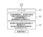
本発明は、航空機の機体に配置される作動油配管の洗浄装置及び洗浄方法に関する。
特開2002-357283号公報(特許文献1)には、水道の給水管及び給湯管の末端部分に配置するシングルレバー式水栓において、給水管及び給湯管と水栓との間の管内に、水撃作用の発生を回避させるピストンを配置した発明が開示されている。特許文献1に記載されている水撃作用防止装置は、一方向に流体が流れる給水管及び給湯管の水栓の近傍に配置される。そして、給水管及び給湯管に生ずる水撃の発生を回避させるとしている。
特開2005-208712号公報(特許文献2)には、一方向に流体が流れる流体通路の無水撃開放方法が開示されている。特許文献2に記載されている流体通路の無水撃開放方法では、アクチュエータ作動式バルブの上流側に配置した振動センサで振動Prを検出して、当該振動検出信号Prがほぼ零となる制御をアクチュエータ作動式バルブに対して行っている。振動センサは、アクチュエータ作動式バルブの上流側近傍に配置される。
特開2008-274871号公報(特許文献3)には、水力発電所におけるインライン水車用の主管路(一方向に流体が流れる流路)に発生する水撃を抑制する水撃抑制装置が開示されている。特許文献3に記載されている水撃抑制装置は、インライン水車の近傍にインライン水車をバイパスするバイパス管路とラプチャーディスクを備える。特許文献3に記載されている水撃抑制装置は、インライン水車の発電機が事故等により系統から切り離された際に、インライン水車の回転数上昇に伴ってインライン水車への流入量が急激に抑制され、その結果発生する水撃を抑制すると共に、水撃の発生を事後に確認するためのものである。
航空機には、補助翼、方向舵、昇降舵などの主操縦翼面に加え、フラップ、スポイラー、スラット、エアブレーキなどの二次操縦翼面等の動翼や、引込脚、ブレーキ、ステアリング、逆噴射装置等の可動部が存在する。これらの可動部にはそれぞれアクチュエータが接続されている。油圧を用いてアクチュエータを駆動する構成においては、このアクチュエータに接続した供給流路及び戻り流路の作動油配管に供給する油圧を制御することで、アクチュエータを駆動し、可動部を動かしている。また、作動油タンクや油圧ポンプ等に対しても、作動油配管が接続されている。
航空機においては、安全性の側面から、独立した複数の油圧系統を備えるのが一般的である。従って、翼内や胴体内に配置される作動油配管の数量は、必然的に多くなる。また、作動油配管は、エルボや継手、分岐部、隔壁を通す際のフィッティング等、多くの部品から構成されており、製造時や分解修理時における作動油配管内の洗浄には多くの工数が必要となっている。従来は、作動油配管の系統毎に洗浄装置を接続して、作動油配管内の洗浄作業と、洗浄の確認作業と、洗浄対象の作動油配管の切替作業とを、繰り返しながら作動油配管内の洗浄を行っていた。
特に旅客機においては、可動部や油圧ポンプ等の数量が多いことに加えて、作動油配管の供給端から装備品端までの距離が10~40mと長い場合が多い。そのため、洗浄作業時における作動油配管の切替作業には、多くの人員と工数とを要していた。
本発明は、航空機の機体に配置される作動油配管の供給流路及び戻り流路を、より短い時間で洗浄する洗浄装置及び洗浄方法を提供することを目的とする。
本発明の洗浄装置は、航空機の第1作動油配管及び第2作動油配管を同時に洗浄する洗浄装置である。洗浄装置は、第1油圧系統に含まれる前記第1作動油配管の供給端に接続される洗浄剤供給流路と、第2油圧系統に含まれる前記第2作動油配管の供給端に接続される洗浄剤戻り流路とを有する洗浄剤循環装置を備える。また、洗浄装置は、前記第1作動油配管の接続端と前記第2作動油配管の接続端との間に配置され、前記第1作動油配管と前記第2作動油配管とを流体接続する弁付連結管と、前記弁付連結管の流路に配置された連結管開閉弁と、制御部とを備える。前記連結管開閉弁は、前記制御部の指示に基づいて前記弁付連結管に流れる洗浄剤の流量を制御する。
本発明の洗浄装置を用いることによって、航空機の機体に配置される作動油配管の供給流路及び戻り流路を、より短い時間で洗浄することができる。
添付の図面は、実施形態の説明を助けるために本明細書に組み込まれる。なお、図面は、本発明を、図示された例および説明された例に限定するものとして解釈されるべきではない。
図1は、洗浄装置における洗浄剤循環装置の油圧回路の一例を概略説明する図である。
図2は、洗浄対象となっている航空機側の2系統の作動油配管の油圧回路と、弁付連結管と、連結管開閉弁との接続を概略説明する図である。
図3は、洗浄装置を用いた配管の洗浄方法を説明するフローチャートの前半部分である。
図4は、洗浄装置を用いた配管の洗浄方法を説明するフローチャートの後半部分である。
図5は、連結管開閉弁の開閉動作(Left)を説明する図表である。
図6は、洗浄装置における洗浄剤循環装置にバイパス流路及びバイパス弁を配置した油圧回路の一例を概略説明する図である。
図7は、洗浄対象となっている航空機側の2系統の作動油配管の油圧回路と、弁付連結管と、連結管開閉弁との接続を概略説明する図である。
図8は、洗浄工程におけるバイパス弁及び連結管開閉弁の開閉タイミングを説明するタイミングチャートである。
図9は、洗浄工程におけるサーボ式のバイパス弁、連結管開閉弁の開閉動作を説明するタイミングチャートである。
図10は、洗浄対象となっている航空機側の2系統の作動油配管の油圧回路と、弁付連結管と、連結管開閉弁との接続例を概略説明する図である。
図11は、連結管開閉弁の開閉動作(Right)を説明する図表である。
図12は、洗浄対象となっている航空機側の4系統の作動油配管の油圧回路と、弁付連結管と、分岐連結管と、連結管開閉弁との接続例を概略説明する図である。
図13は、2系統の供給流路と、1系統の戻り流路とを有する洗浄剤循環装置を説明する図である。
図14は、洗浄対象となっている奇数の供給端を有する5系統の作動油配管の油圧回路と、弁付連結管と、分岐連結管と、連結管開閉弁との接続例を概略説明する図である。
図15は、奇数の供給端を有する作動油配管を洗浄する、連結管開閉弁の開閉動作(Center)を説明する図表である。
図16は、供給弁、バイパス弁、連結管開閉弁24を、図15に示す開閉動作に基づいて制御する際のタイミングチャートである。
図17は、両端に装備品端を有する第6作動油配管を含む3系統の作動油配管の油圧回路と、弁付連結管と、多分岐弁付連結管と、連結管開閉弁と、連結管との接続例を概略説明する図である。
図18は、4系統の供給流路と、3系統の戻り流路とを有する洗浄剤循環装置を説明する図である。
図19は、両端に装備品端を有する第6作動油配管を含む5系統の作動油配管の油圧回路と、弁付連結管と、多分岐弁付連結管と、分岐連結管と、連結管開閉弁と、連結管との接続例を概略説明する図である。
図20は、Leftの作動油配管(例えば、左翼に配置される作動油配管)を洗浄する際の、連結管開閉弁の開閉動作を説明する図表である。
図21は、洗浄対象となっている奇数の供給端を有する5系統の作動油配管の油圧回路と、弁付連結管と、分岐連結管と、連結管開閉弁と、連結管との接続例を概略説明する図である。
図22は、Centerの作動油配管(例えば、胴体に配置される作動油配管)を洗浄する際の、連結管開閉弁の開閉動作を説明する図表である。
図23は、Rightの作動油配管(例えば、右翼に配置される作動油配管)を洗浄する際の、連結管開閉弁の開閉動作を説明する図表である。
以下の詳細な説明においては、実施形態の包括的な理解を提供するために、説明の目的で多くの詳細な特定事項が開示される。しかし、一又は複数の実施形態は、これらの詳細な特定事項なしで実行可能であることが明らかである。添付図面を参照して、洗浄装置を実施するための形態を、以下に説明する。以下に示す洗浄装置及び洗浄方法は、航空機の翼や胴体等の機体に配置される複数の作動油配管の内部を、効率良く短時間で洗浄するためのものであり、説明の都合上、多くの作動油配管の系統の中から、一部分を取り出して、簡単な部分から説明する。
(T分岐部96を有する2系統の作動油配管を洗浄する実施形態)
先ず、図1乃至図6を参照して、第1作動油配管(91、91A)及び第2作動油配管(92、92A)で構成される2系統の作動油配管(供給流路及び戻り流路)を洗浄する実施形態について説明する。なお、第1作動油配管は、例えば、第1油圧系統に含まれ、第2作動油配管は、第1油圧系統とは別の油圧系統に含まれる。
先ず、図1乃至図6を参照して、第1作動油配管(91、91A)及び第2作動油配管(92、92A)で構成される2系統の作動油配管(供給流路及び戻り流路)を洗浄する実施形態について説明する。なお、第1作動油配管は、例えば、第1油圧系統に含まれ、第2作動油配管は、第1油圧系統とは別の油圧系統に含まれる。
図1は、洗浄装置10における洗浄剤循環装置12の油圧回路の一例を概略説明する図である。図2は、洗浄対象となっている航空機側の第1作動油配管(91、91A)及び第2作動油配管(92、92A)で構成される2系統の作動油配管の油圧回路と、洗浄装置10における洗浄剤循環装置12と、弁付連結管22と、連結管開閉弁24との接続例を概略説明する図である。図3及び図4は、洗浄装置10を用いた配管の洗浄方法を説明するフローチャートである。図5は、連結管開閉弁24の開閉動作(Left)を説明する図表である。
図1には、ポンプ部30と、洗浄装置10に含まれる洗浄剤循環装置12とを表してある。ポンプ部30は、供給流路31Pを介して所定圧力及び所定流量の洗浄剤を圧送する。また、ポンプ部30は、洗浄に用いた洗浄剤を、戻り流路32Pを介して回収する。洗浄剤には、例えばリン酸エステル系の合成油等を用いることができる。
洗浄剤循環装置12は、供給流路31と、戻り流路32と、制御部14とを備えている。また、必要に応じて洗浄剤循環装置12は、入力部15、表示部16、記憶部17、出力部18、弁38、弁39、パージ剤40、パージ弁41、パージ逆止弁45、パージ逆止弁46、圧力計47、フローサイト48(flow sight pipe)、温度計49、フィルタ50、フィルタ弁52、流量計56、サンプラー57を設けることができる。
供給流路31は、ポンプ部30の供給流路31Pと、航空機の第1作動油配管91とを接続して、第1作動油配管91に対して洗浄剤の供給を行う流路である。
戻り流路32は、ポンプ部30の戻り流路32Pと、航空機の第2作動油配管92とを接続して、第2作動油配管92から洗浄剤を戻す流路である。
弁38は、ポンプ部30と洗浄剤循環装置12との間の供給流路31Pと、ポンプ部30と洗浄剤循環装置12との間の戻り流路32Pに、それぞれ配置される。供給流路31P及び戻り流路32Pを洗浄剤循環装置12から取り外す際には、弁38を閉鎖しておく。ポンプ部30と洗浄剤循環装置12とを接続して、作動油配管の洗浄を行う際には、弁38を開いて洗浄剤の循環が可能な状態にしておく。弁38として、手動で開閉を行う弁や、電磁弁等を用いることができる。
弁39は、洗浄剤循環装置12と作動油配管(例えば、第1作動油配管91)との間の供給流路31Sと、洗浄剤循環装置12と作動油配管(例えば、第2作動油配管92)との間の戻り流路32Sに、それぞれ配置される。供給流路31S及び戻り流路32Sを洗浄剤循環装置12から取り外す際には、弁39を閉鎖しておく。洗浄剤循環装置12と作動油配管とを接続して、作動油配管の洗浄を行う際には、弁39を開いて洗浄剤の循環が可能な状態にしておく。弁39として、手動で開閉を行う弁や、電磁弁等を用いることができる。
パージ剤40は、作動油配管の洗浄が終了した後に、洗浄剤を除去する工程において、作動油配管内に圧送される流体である。パージ剤40として窒素ガス等の不活性ガスを用いることができる。
パージ弁41は、パージ剤40を、供給流路31を介して作動油配管に供給したり、供給を遮断するために用いる弁である。パージ弁41は、通常は閉じておき、洗浄剤を除去するパージングの工程において開く。
パージ逆止弁45は、洗浄時等において、洗浄剤が供給流路31のパージ弁41側に流入することを防止する逆止弁である。
パージ逆止弁46は、パージング工程等において、パージ剤40が供給流路31の圧力計47や、ポンプ部30側に流入することを防止する逆止弁である。
圧力計47は、供給流路31に配置され、洗浄時における洗浄剤の供給圧力を計測する機器である。
フローサイト48は、戻り流路32に配置され、洗浄剤の流れを検視する検視管である。
温度計49は、戻り流路32に配置され、洗浄剤の温度を計測する機器である。
フィルタ50は、戻り流路32に配置され、洗浄工程において、作動油配管内に存在していた塵埃(コンタミネーション)を捕集して、ポンプ部30に流入することを防止する機器である。
フィルタ弁52は、戻り流路32においてフィルタ50と並列に配置される。フィルタ弁52は、通常は閉じておき、作動油配管内を循環した洗浄剤をフィルタ50に流す。洗浄終了後のパージング工程においては、フィルタ弁52を開いて、フィルタ50を通さずにパージ剤40を下流側に向けて流す。
流量計56は、戻り流路32に配置され、洗浄中における洗浄剤の流量を計測する機器である。
サンプラー57は、戻り流路32に配置され、洗浄中に戻ってきた洗浄剤に含まれる塵埃(コンタミネーション)の量を計測して、洗浄の終了を判断するための塵埃検査機器、又はその塵埃検査機器と戻り流路32とを接続するためのコネクタである。
制御部14は、圧力計47、温度計49、流量計56、サンプラー57等の各種計測機器の計測値を取得するとともに、入力部15、表示部16、記憶部17、出力部18等の周辺機器との間で情報の送受を行う。また、制御部14は、パージ弁41やフィルタ弁52、図2を参照して後述される連結管開閉弁24の制御を行う。制御部14は、予めプログラミングされた順序に従って、各周辺機器から情報や指令を入力し、各周辺機器に対して情報や指令を出力することで、作動油配管の洗浄を自動化することができる。
入力部15は、スイッチやボタン、キーボード等を含み、作業者が自動洗浄の開始指示や、各種洗浄条件の決定、非常停止等の指示を入力して、入力された指示を制御部14に対して出力する機器である。
表示部16は、表示パネルや表示ランプ等の表示装置から構成され、制御部14の指示に基づいて、各種計測機器の計測値の表示や、自動洗浄時における工程の表示、自動洗浄時における各種ステータスの表示、その他の表示を行う。
記憶部17は、各種計測機器の計測値の記憶や、自動洗浄の経過情報、自動洗浄時における各種ステータスの記憶、及び自動計測に関するプログラムの記憶等を行う。
出力部18は、制御部14の指示に基づいて、連結管開閉弁24に対して開閉等の制御指令を出力する。また、出力部18は、制御部14の指示に基づき、外部に接続されるコンピュータPCに対して、各種計測機器の計測値の出力や、自動洗浄時における工程情報の出力、各種ステータスの出力を行うことができる。
次に、図2を参照して、航空機側の油圧回路と、洗浄装置10との接続例について説明する。
図2を参照して、航空機側(例えば主翼。)には、第1作動油配管91、91A、91Bと、第2作動油配管92、92A、92Bとが搭載されている。第1作動油配管91A、91B及び第2作動油配管92A、92Bに連通する装備品端97には、洗浄装置10の弁付連結管22及び連結管開閉弁24を接続してある。なお、装備品端97は、航空機の使用時に、任意の装置又は部材が接続される装備品側の接続端である。
第1作動油配管91の一端(例えば主翼における胴体との接続側。)には、供給端95が形成されている。航空機の内部に配置される第1作動油配管91の途中には、T分岐部96が形成されており、第1作動油配管91A(第1分岐部)と第1作動油配管91B(第2分岐部)とに分岐している。第1作動油配管91Aと第1作動油配管91Bの端部には、装備品端(接続端)97が、それぞれ設けられている。供給端95は、例えば航空機の胴体側に接続される接続部である。また、装備品端97は、操縦装置のアクチュエータ側に接続する接続部である。
第2作動油配管92の一端(例えば主翼における胴体との接続側。)には、供給端95が形成されている。航空機の内部に配置される第2作動油配管92の途中には、T分岐部96が形成されており、第2作動油配管92A(第1分岐部)と第2作動油配管92B(第2分岐部)とに分岐している。第2作動油配管92Aと第2作動油配管92Bの端部には、装備品端(接続端)97が、それぞれ設けられている。装備品端97は、例えば操縦装置のアクチュエータ側に接続する接続部である。
図2に記載の例では、第1作動油配管91A(第1分岐部)と第2作動油配管92A(第1分岐部)との間に、弁付連結管22が配置されている。そして、第1作動油配管91Aと第2作動油配管92Aとが、弁付連結管22を介して流体接続されている。また、第1作動油配管91B(第2分岐部)と第2作動油配管92B(第2分岐部)との間に、他の弁付連結管22が配置されている。そして、第1作動油配管91Bと第2作動油配管92Bとが、当該他の弁付連結管22を介して流体接続されている。
(配管の洗浄方法)
次に、図3及び図4を参照して、作動油配管の洗浄方法について説明する。
次に、図3及び図4を参照して、作動油配管の洗浄方法について説明する。
ステップS10「航空機の作動油配管の装備品端に連結管を接続する。」にて作業者は、第1作動油配管91Aの装備品端97と、第2作動油配管92Aの装備品端97との間に、弁付連結管22を接続する。同様に、第1作動油配管91Bの装備品端97と、第2作動油配管92Bの装備品端97との間に、弁付連結管22を接続する。弁付連結管22には、洗浄剤の通過と停止とを制御する連結管開閉弁24が配置されている。
次に、ステップS12「ポンプ部、洗浄剤循環装置及び航空機の作動油配管に、配管を接続する。」にて作業者は、図1に示すポンプ部30の供給流路31P(配管)を、洗浄剤循環装置12の供給流路31に接続し、戻り流路32P(配管)を、洗浄剤循環装置12の戻り流路32に接続する。そして、洗浄剤循環装置12の供給流路31に供給流路31Sを接続し、供給流路31Sを図2に示す航空機の第1作動油配管91の供給端95(ポートAO)に接続する。同様に、洗浄剤循環装置12の戻り流路32に戻り流路32Sを接続し、戻り流路32Sを図2に示す航空機の第2作動油配管92の供給端95(ポートAN)に接続する。
次に同じステップS12の「連結管開閉弁の制御線を洗浄剤循環装置に接続する。」にて作業者は、連結管開閉弁24に制御信号を伝達する制御線24Cを、それぞれ遠く離れた場所に配置してある洗浄剤循環装置12の出力部18に接続する。このように洗浄剤循環装置12と連結管開閉弁24とを制御線24Cを介して接続することによって、連結管開閉弁24の開閉動作を、遠く離れた場所に配置してある洗浄剤循環装置12を用いて遠隔制御することができるようになる。
次に、ステップS14「洗浄剤を充填する」にて、ポンプ部30を起動し、閉じていた弁38、弁39を開いて、洗浄剤の循環が可能な状態に設定する。そして、作業者が入力部15等を操作して、制御部14に対して配管洗浄の開始を指示する。
次のステップS16「第n配管洗浄」にて制御部14は、ポンプ部30に対して所定の圧力及び流量を供給する制御指令を出力する。そして、制御部14は、出力部18を介して連結管開閉弁24の開閉動作を指示する。その結果、時間経過タイマーは、時間計測を開始して、洗浄装置10は、洗浄を開始する。制御部14は、必要に応じて、圧力計47、温度計49、流量計56、サンプラー57等の各種計測機器の計測値を取得して、所定の時刻毎(例えば、所定の時間間隔毎)に記憶部17に記憶してゆく。計測値は、表示部16に表示したり、出力部18を介して外部に接続されるコンピュータPCに出力することができる。
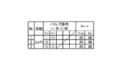
例えば、第1配管洗浄工程(No.1)においては、図5に示すように、連結管開閉弁24(R-5)を閉じて、連結管開閉弁24(R-7)を開く指示を出力する。なお、図5に示す洗浄条件では、第1作動油配管91の供給端95(ポートAO)を供給流路31(Press)に接続し、第2作動油配管92の供給端95(ポートAN)を戻り流路32(Ret)に接続する。
図5に示す第1配管洗浄工程では、図2に示す第1作動油配管91、91A及び、第2作動油配管92、92Aを洗浄する。また、第2配管洗浄工程では、図2に示す第1作動油配管91、91B及び、第2作動油配管92、92Bを洗浄する。そして、最後の第3配管洗浄工程では、図2に示す第1作動油配管91、91A、91B及び、第2作動油配管92、92A、92Bの全てを洗浄する。なお、洗浄対象の作動油配管の断面積が大きい場合には、一般的に洗浄剤の流量を多くする。
洗浄剤の供給に関する洗浄条件として、例えば第1配管洗浄工程(No.1)及び第2配管洗浄工程(No.2)において、洗浄剤の油温を100°F、流量の最低値を8.0GPM(Gallon Per Minute)、洗浄剤の圧力を最大900PSI(Pound-force per Square Inch)、塵埃の量(コンタミネーションレベル)を所定の値以下(CLASS3より清浄。)と定めることができる。また、第3配管洗浄工程(No.3)においては、配管に並列部分が存在するので、洗浄剤の流量の最低値を10.0GPMに高めることができる。
次のステップS18「所定時間経過?」にて制御部14は、時間経過タイマーの計数値が、所定の待ち時間T1(例えば、5分。)を経過するのを待つ処理を行う。時間経過タイマーの計数値が、所定の時間T1を経過した場合には、制御部14が実行する処理は次に進む。
次のステップS20「コンタミネーション検査OK?」にて制御部14は、必要に応じて、サンプラー57が計測する洗浄剤に含まれる塵埃の量(コンタミネーションレベル)が所定の値以下(例えばCLASS3より清浄。)となるまで待つ処理(確認時間T2)を行う。サンプラー57が計測する塵埃の量が所定の値以下に収束した場合には、制御部14が実行する処理は、次のステップS22に進む。なお、作動油配管の洗浄時間は、待ち時間T1+確認時間T2の時間(T1+T2)となる。
次のステップS22「n=n+1」にて制御部14は、次の洗浄工程(例えばNo.2)を設定する。
次のステップS24「n=Nmax?」にて制御部14は、最後の洗浄工程が終了したか否かの判断を行う。もし、最後の洗浄工程が終了していない場合には、ステップS16に戻って、次の洗浄工程(例えば図5に示すNo.2の第2配管洗浄工程。)を実行する。もし、最後の洗浄工程が終了したと判断した場合には、制御部14が実行する処理は、図4に示すステップS26「パージング」に進む。
ステップS26にて制御部14は、必要に応じてパージングを行う。パージング工程において制御部14は、図1に示すフィルタ弁52を開く指令を出力し、パージ弁41を開く指示を出力する。そして、例えば図5に示す洗浄工程(No.1~3)に沿って、図2に示す第1作動油配管91、91A、91B及び、第2作動油配管92、92A、92Bの洗浄剤を除去する処理を行う。ステップS26にて洗浄剤の除去が終了した場合には、ステップS28「洗浄剤循環装置と、航空機の作動油配管との間の配管を取り外す。洗浄剤循環装置から連結管開閉弁の制御線を外す。」の処理に進む。
ステップS28にて作業者は、弁39を閉じて、供給流路31S及び戻り流路32Sを航空機の供給端95から、それぞれ取り外す作業を行う。そして、連結管開閉弁24の制御線24Cを取り外す作業を行う。
次のステップS30「航空機の作動油配管の装備品端から連結管を外す。航空機の作動油配管の装備品端に止栓を取り付ける。」にて作業者は、第1作動油配管91A、91B及び、第2作動油配管92A、92Bの装備品端97に接続されていた弁付連結管22を取り外す。そして、装備品端97及び供給端95に止栓を取り付ける作業を行う。ステップS30の作業が終了すると配管洗浄が終了する。
上述のように洗浄装置10を用いることによって、第1作動油配管91Aから第1作動油配管91Bへの洗浄剤の流路の切り替えや、第2作動油配管92Aから第2作動油配管92Bへの洗浄剤の流路の切り替えを、自動で行うことが可能となる。これにより、図3及び図4に示すステップS12、S28、S30の配管の接続作業又は配管の取り外し作業の回数を減らして、短時間、且つ少ない作業員で、作動油配管の洗浄を行うことができる。
なお、上記の連結管開閉弁24としてソレノイドバルブを用いることもできるし、制御部14の指示に基づいて弁付連結管22の内部を流れる洗浄剤の流量を刻々変化させるサーボ弁や、ショックレス弁を用いることができる。サーボ弁やショックレス弁を用いて、弁付連結管22の内部を流れる洗浄剤の流量を徐々に変化させることによって、作動油配管内を流れる洗浄剤が急停止することによって生ずる水撃を抑制することもできる。
(洗浄剤循環装置12の供給流路31と戻り流路32との間にバイパス流路33及びバイパス弁34を配置した実施形態)
次に、図6乃至図9を参照して、洗浄剤循環装置12にバイパス流路33及びバイパス弁34を配置した構成について説明する。図6乃至図9に示す構成を用いることによって、第1作動油配管91及び第2作動油配管92の先端部の装備品端(接続端)97に接続した連結管開閉弁24の開閉動作により、作動油配管に発生する可能性がある水撃を緩和することができる。
次に、図6乃至図9を参照して、洗浄剤循環装置12にバイパス流路33及びバイパス弁34を配置した構成について説明する。図6乃至図9に示す構成を用いることによって、第1作動油配管91及び第2作動油配管92の先端部の装備品端(接続端)97に接続した連結管開閉弁24の開閉動作により、作動油配管に発生する可能性がある水撃を緩和することができる。
図6は、洗浄装置10における洗浄剤循環装置12に、バイパス流路33及びバイパス弁34を配置した油圧回路の一例を概略説明する図である。図7は、洗浄対象となっている航空機側の第1作動油配管91及び第2作動油配管92で構成される2系統の作動油配管の油圧回路と、洗浄装置10における洗浄剤循環装置12と、弁付連結管22と、連結管開閉弁24との接続を概略説明する図である。図8は、洗浄工程におけるバイパス弁34及び連結管開閉弁24の開閉タイミングを説明するタイミングチャートである。図9は、洗浄工程におけるサーボ式のバイパス弁34、連結管開閉弁24の開閉動作を説明するタイミングチャートである。なお、図1及び図2にて説明した部位と同様の作用を有する部位については、同一の符号を付してその説明を省略する。
図6に示す洗浄剤循環装置12の供給流路31と戻り流路32との間には、バイパス流路33及びバイパス弁34を配置してある。また、出力部18と連結管開閉弁24との間には、中継器19を配置してある。中継器19をなるべく連結管開閉弁24の近傍に配置することで、連結管開閉弁24に対する制御線24Cの配線を容易にすることができる。
次に、図7を参照して、航空機側の油圧回路と、洗浄装置10との接続例について説明する。図7に示す航空機側には、第1作動油配管91と、第2作動油配管92とが搭載されている。第1作動油配管91及び第2作動油配管92に連通する装備品端(接続端)97には、洗浄装置10の弁付連結管22及び連結管開閉弁24を接続してある。
次に、洗浄装置10と各作動油配管との接続について説明する。図6に示す洗浄剤循環装置12の供給流路31に供給流路31Sを接続し、供給流路31Sを図7に示す航空機の第1作動油配管91の供給端95に接続する。同様に、洗浄剤循環装置12の戻り流路32に戻り流路32Sを接続し、戻り流路32Sを図7に示す航空機の第2作動油配管92の供給端95に接続する。また、連結管開閉弁24の制御線24Cを、中継器19に接続する。図6及び図7に示す洗浄装置10を用いた作動油配管の洗浄方法は、図3及び図4に示した洗浄方法に準ずるものである。よって、図3及び図4に示した洗浄方法との相違点について以下に説明する。
(連結管開閉弁24及びバイパス弁34の開閉制御)
連結管開閉弁24及びバイパス弁34の開閉制御について、図8を用いて説明する。図1及び図2に示した作動油配管の洗浄方法では、連結管開閉弁24の開閉制御を行うことで、第n配管洗浄工程(図3に示すステップS16の処理、図5に示す第n配管洗浄工程の「No.」の欄を参照。)の洗浄を切り替えていた。これに対し、図6及び図7に示す洗浄装置10では、図8に示すように、バイパス弁34及び連結管開閉弁24の双方を制御することで、作動油配管等に作用する水撃を減少させつつ、第n配管洗浄工程の洗浄を切り替えている。
連結管開閉弁24及びバイパス弁34の開閉制御について、図8を用いて説明する。図1及び図2に示した作動油配管の洗浄方法では、連結管開閉弁24の開閉制御を行うことで、第n配管洗浄工程(図3に示すステップS16の処理、図5に示す第n配管洗浄工程の「No.」の欄を参照。)の洗浄を切り替えていた。これに対し、図6及び図7に示す洗浄装置10では、図8に示すように、バイパス弁34及び連結管開閉弁24の双方を制御することで、作動油配管等に作用する水撃を減少させつつ、第n配管洗浄工程の洗浄を切り替えている。
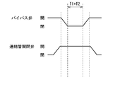
図8を参照して、作動油配管の洗浄時間(待ち時間T1+確認時間T2)の前から洗浄時間の後までの期間における、バイパス弁34及び連結管開閉弁24の開閉タイミングについて説明する。
図8に示すように、作動油配管の洗浄を行う前の段階においては、バイパス弁34が開いており、連結管開閉弁24は閉じた状態となっている。この場合には、ポンプ部30から圧送される洗浄剤は、全て供給流路31からバイパス流路33を通って戻り流路32に流れ、再びポンプ部30に戻る。
次に、図3に示すステップS16「第n配管洗浄」における処理において、作動油配管の洗浄を開始する場合には、制御部14は、先ず連結管開閉弁24を閉じた状態から開いた状態に設定する。このとき、ポンプ部30から圧送される洗浄剤の殆どは、供給流路31からバイパス流路33を通って戻り流路32に流れ、再びポンプ部30に戻る。また、ポンプ部30から圧送される洗浄剤の一部は、供給流路31から第1作動油配管91、弁付連結管22、第2作動油配管92を経由して戻り流路32に流れ、ポンプ部30に戻る。
その後、所定の待ち時間T0後に、バイパス弁34を閉じる。すると、ポンプ部30から圧送される洗浄剤は、供給流路31から第1作動油配管91、弁付連結管22、第2作動油配管92を経由して戻り流路32に流れてポンプ部30に戻り、作動油配管の洗浄を行う(図3に示すステップS16乃至S20の処理。)。
作動油配管の洗浄時間(待ち時間T1+確認時間T2)が経過した場合には、制御部14はバイパス弁34を開く指示を出力する。このとき、ポンプ部30から圧送される洗浄剤の殆どは、供給流路31からバイパス流路33を通って戻り流路32に流れるようになる。その後、所定の待ち時間T0後に、連結管開閉弁24を閉じる。
このように、予め開いてあったバイパス弁34を、連結管開閉弁24を開いた後に閉じて作動油配管の洗浄を開始することによって、作動油配管における洗浄剤の急激な圧力変化を減少させて、水撃を減少させることができる。また、作動油配管の洗浄時間(T1+T2)経過後に連結管開閉弁24を閉じる前に、閉じてあったバイパス弁34を開くことによって、作動油配管における洗浄剤の急激な流量変化を緩和させて、水撃を減少させることができる。
次に、図9を参照して、バイパス弁34、連結管開閉弁24にサーボ弁又はショックレス弁を用いた場合における、バイパス弁34、連結管開閉弁24の開閉動作について説明する。バイパス弁34、連結管開閉弁24にサーボ弁やショックレス弁を用いる場合においても、作動油配管の洗浄を行う前の段階においては、バイパス弁34を開いておき、連結管開閉弁24は閉じておく。
次に、図3に示すステップS16「第n配管洗浄」における処理において、作動油配管の洗浄を開始する場合には、制御部14は、連結管開閉弁24を閉じた状態から、徐々に開いてゆく。その後、バイパス弁34を徐々に閉じて、ポンプ部30から圧送された洗浄剤を、供給流路31から第1作動油配管91、弁付連結管22、第2作動油配管92を経由して戻り流路32に流して、作動油配管の洗浄を行う(図3に示すステップS16乃至S20の処理。)。
作動油配管の洗浄時間(待ち時間T1+確認時間T2)が経過した場合には、制御部14はバイパス弁34徐々に開く指示を出力する。このとき、ポンプ部30から圧送される洗浄剤の流れは、作動油配管からバイパス流路33に徐々に切り替わる。その後、連結管開閉弁24を徐々に閉じて、ポンプ部30から圧送される洗浄剤の流れを、作動油配管からバイパス流路33に徐々に切り替える。
このように、バイパス弁34及び連結管開閉弁24の開閉動作を徐々に行うことによって、作動油配管からバイパス流路33への洗浄剤の流れや、バイパス流路33から作動油配管への洗浄剤の流れを徐々に変化させることができる。そして、作動油配管における急激な圧力変化を減少させて、水撃を減少させることができる。また、水撃を押さえつつ、短時間で流路の切り替えを行うことも可能となる。
(洗浄剤循環装置12の供給流路31と戻り流路32との間にバイパス流路33及びバイパス弁34を配置し、複数の連結管開閉弁24を制御する実施形態)
次に、図6、図10及び図11を参照して、洗浄剤循環装置12にバイパス流路33及びバイパス弁34を配置して、第1作動油配管91A、91B、91C及び第2作動油配管92A、92B、92Cを自動で洗浄する実施形態について説明する。図6、図10及び図11に示す実施形態においても、洗浄前後の作動油配管に発生する水撃を緩和することができる。
次に、図6、図10及び図11を参照して、洗浄剤循環装置12にバイパス流路33及びバイパス弁34を配置して、第1作動油配管91A、91B、91C及び第2作動油配管92A、92B、92Cを自動で洗浄する実施形態について説明する。図6、図10及び図11に示す実施形態においても、洗浄前後の作動油配管に発生する水撃を緩和することができる。
図6は、洗浄装置10における洗浄剤循環装置12にバイパス流路33及びバイパス弁34を配置した油圧回路の一例を概略説明する図である。図10は、洗浄対象となっている航空機側の第1作動油配管91、91A、91B、91C及び第2作動油配管92、92A、92B、92Cで構成される2系統の作動油配管の油圧回路と、洗浄装置10における洗浄剤循環装置12と、弁付連結管22と、連結管開閉弁24との接続を概略説明する図である。図11は、連結管開閉弁24の開閉動作を説明する図表である。なお、図1、図2、図5乃至図8にて説明した部位と同様の作用を有する部位については、同一の符号を付してその説明を省略する。
図10を参照して、航空機側の油圧回路と、洗浄装置10との接続例について説明する。図10に示す航空機側には、第1作動油配管91、91A、91B、91C及びT分岐部96と、第2作動油配管92、92A、92B、92C及びT分岐部96とが搭載されている。第1作動油配管91A、91B、91及び第2作動油配管92A、92B、92Cに連通する装備品端(接続端)97には、洗浄装置10の弁付連結管22及び連結管開閉弁24を接続してある。
次に、洗浄装置10と各作動油配管との接続について説明する。図6に示す洗浄剤循環装置12の供給流路31に供給流路31Sを接続し、供給流路31Sを図10に示す航空機の第1作動油配管91の供給端95(ポートV)に接続する。同様に、洗浄剤循環装置12の戻り流路32に戻り流路32Sを接続し、戻り流路32Sを図10に示す航空機の第2作動油配管92の供給端95(ポートU)に接続する。また、連結管開閉弁24の制御線24Cを、中継器19に接続する。なお、図6及び図10に示す洗浄装置10を用いた作動油配管の洗浄方法は、図1乃至図5に示した洗浄方法に準ずるものである。よって、図1乃至図5に示した洗浄方法との相違点について以下に説明する。
(連結管開閉弁24の開閉動作と洗浄条件の説明)
図11を参照して、図10に示す作動油配管の洗浄方法の一例について説明する。図10に示すような、分岐を有する第1作動油配管91A、91B、91C、及び第2作動油配管92A、92B、92Cを洗浄する場合においても、制御部14が図11に示す連結管開閉弁24の開閉動作を行うことによって、少ない段取り替え作業で、短時間で洗浄を終了することができる。
図11を参照して、図10に示す作動油配管の洗浄方法の一例について説明する。図10に示すような、分岐を有する第1作動油配管91A、91B、91C、及び第2作動油配管92A、92B、92Cを洗浄する場合においても、制御部14が図11に示す連結管開閉弁24の開閉動作を行うことによって、少ない段取り替え作業で、短時間で洗浄を終了することができる。
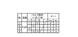
図11に示す実施形態では、第1配管洗浄工程(No.1)において、第1作動油配管91、91A及び第2作動油配管92、92Aを洗浄する。次の第2配管洗浄工程(No.2)において、第1作動油配管91、91B及び第2作動油配管92、92Bを洗浄する。次の第3配管洗浄工程(No.3)において、第1作動油配管91、91C及び第2作動油配管92、92Cを洗浄する。最後の第4配管洗浄工程(No.4)においては、再び第1作動油配管91、91A、91B及び第2作動油配管92、92A、91Bを洗浄する。
洗浄剤の供給に関する洗浄条件として、例えば第1配管洗浄工程(No.1)及び第2配管洗浄工程(No.2)において、洗浄剤の油温を100°F、流量の最低値を8.0GPM、洗浄剤の圧力を最大900PSI、塵埃の量(コンタミネーションレベル)を所定の値以下(CLASS3より清浄。)と定めることができる。また、第3配管洗浄工程(No.3)においては、洗浄対象の作動油配管の断面積が大きいので、洗浄剤の流量の最低値を10.0GPMに高めることができる。また、第4配管洗浄工程(No.4)においては、配管に並列部分が存在するので、洗浄剤の流量の最低値を10.0GPMに高めることができる。
上記の説明では、図10に示す航空機の作動油配管を、図6に示す洗浄剤循環装置12を用いて自動洗浄する実施形態について説明したが、図1に示した洗浄剤循環装置12を用いて自動洗浄を行うこともできる。
(4系統の作動油配管を洗浄する実施形態)
次に、図1、図12を参照して、4系統の作動油配管を洗浄する実施形態について説明する。図12は、洗浄対象となっている航空機側の4系統の作動油配管の油圧回路と、洗浄装置10における洗浄剤循環装置12と、弁付連結管22と、分岐連結管23と、連結管開閉弁24との接続例を概略説明する図である。
次に、図1、図12を参照して、4系統の作動油配管を洗浄する実施形態について説明する。図12は、洗浄対象となっている航空機側の4系統の作動油配管の油圧回路と、洗浄装置10における洗浄剤循環装置12と、弁付連結管22と、分岐連結管23と、連結管開閉弁24との接続例を概略説明する図である。
図2に示した航空機の作動油配管は、第1作動油配管91、91A、及び第2作動油配管92、92Aの2系統であり、T分岐部96を介して分岐した作動油配管であった。図12に示す航空機の作動油配管は、T分岐部96を有さない独立した4系統の作動油配管(第1作動油配管91、第2作動油配管92、第3作動油配管93、第4作動油配管94)を洗浄する実施形態である。
図1に示す洗浄剤循環装置12を用いて、図12に示す作動油配管を自動で洗浄を行う場合には、図12に示すように、第1作動油配管91に連通する装備品端(接続端)97と、第3作動油配管93に連通する装備品端(接続端)97とを、分岐連結管23を用いて接続する。同様に、第2作動油配管92に連通する装備品端(接続端)97と、第4作動油配管94に連通する装備品端(接続端)97とを、分岐連結管23を用いて接続する。
更に、2つの分岐連結管23の装備品端(接続端)97同士を、弁付連結管22で接続する。また、第3作動油配管93の装備品端(接続端)97と、第4作動油配管94の装備品端(接続端)97とを、弁付連結管22を用いて接続する。このように各作動油配管と、分岐連結管23と、弁付連結管22、連結管開閉弁24とを接続することで、図2に示した作動油配管の油圧回路と同様な回路構成にすることができる。図12に示す連結管開閉弁24の開閉動作は、図2乃至図5にて説明した開閉動作と同一であるので、その説明は省略する。
(奇数の供給端を有する作動油配管を洗浄する実施形態)
次に、図13乃至図16を参照して、奇数の供給端を有する作動油配管を洗浄する実施形態について説明する。
次に、図13乃至図16を参照して、奇数の供給端を有する作動油配管を洗浄する実施形態について説明する。
図13は、2系統の供給流路31と、1系統の戻り流路32を有する洗浄剤循環装置12を説明する図である。図14は、洗浄対象となっている奇数の供給端を有する5系統の作動油配管の油圧回路と、洗浄装置10における洗浄剤循環装置12と、弁付連結管22と、分岐連結管23と、連結管開閉弁24との接続例を概略説明する図である。図15は、奇数の供給端を有する作動油配管を洗浄する、連結管開閉弁24の開閉動作を説明する図表である。図16は、図13に示す供給弁35C、35D、バイパス弁34C、34D、図14に示す連結管開閉弁24(L-6、L-9、L-10)を図15に示す開閉動作に基づいて制御する際のタイミングチャートである。なお、図1、図2、図5乃至図12にて説明した部位と同様の作用を有する部位については、同一の符号を付してその説明を省略する。
先ず、図13を用いて、2系統の供給流路31と、1系統の戻り流路32を有する洗浄剤循環装置12の構成について説明する。
図13に示す洗浄剤循環装置12の供給流路31は、2つの供給流路31C、31Dに分岐してある。供給流路31Cには、洗浄剤の供給及び遮断を制御する供給弁35Cを配置し、供給流路31Dには、洗浄剤の供給及び遮断を制御する供給弁35Dを配置して、洗浄剤の供給流路の切り替えを可能にしている。また、2つの供給流路31C、31Dには、それぞれパージ剤40を供給するパージ弁41と、パージ逆止弁45、46とを接続することができる。また、2つの供給流路31C、31Dと戻り流路32との間には、バイパス流路33及びバイパス弁34C、34Dを配置することができる。
次に、図14を用いて、奇数の供給端95を有する5系統の作動油配管の油圧回路と、洗浄装置10における洗浄剤循環装置12と、弁付連結管22と、分岐連結管23と、連結管開閉弁24との接続例について説明する。
図14に示す作動油配管は、一つのT分岐部96を有する第1作動油配管91、91A、91Bと、2つのT分岐部96を有する第2作動油配管92、92A、92B、92Cと、第3作動油配管93と、第4作動油配管94と、第5作動油配管98とを有している。
図13に示す洗浄剤循環装置12を用いて、図14に示す作動油配管を自動で洗浄を行う場合には、図14に示すように、第1作動油配管91Aに連通する装備品端(接続端)97と、第3作動油配管93に連通する装備品端(接続端)97とを、分岐連結管23を用いて接続する。また、第2作動油配管92Aに連通する装備品端(接続端)97と、第4作動油配管94に連通する装備品端(接続端)97とを、分岐連結管23を用いて接続する。更に、2つの分岐連結管23の装備品端(接続端)97同士を、弁付連結管22で接続し、第3作動油配管93に連通する装備品端(接続端)97と、第4作動油配管94に連通する装備品端(接続端)97とを、弁付連結管22を用いて接続する。
そして、第5作動油配管98に連通する別の装備品端(接続端)97と、第2作動油配管92Cに連通する装備品端(接続端)97とを、連結管25を用いて接続する。
次に、図13に示す洗浄剤循環装置12と、図14に示す作動油配管の供給端95との接続について説明する。
図13に示す洗浄剤の供給流路31S(ポートA)は、図14に示す航空機の第1作動油配管91の供給端95(ポートA)に接続する。図13に示す洗浄剤の戻り流路32S(ポートB)は、図14に示す航空機の第2作動油配管92の供給端95(ポートB)に接続する。また、図13に示す洗浄剤の供給流路31S(ポートC)は、図14に示す航空機の第5作動油配管98の供給端95(ポートC)に接続する。
次に、図15及び図16を参照して、図14に示す作動油配管を洗浄する際の、連結管開閉弁24の開閉動作について説明する。なお、図16に示すように、第1配管洗浄工程(No.1)から第4配管洗浄工程(No.4)の間では、図13に示す洗浄剤循環装置12の供給弁35Cを開いておき、供給弁35Dは閉じておく。
図15及び図16に示す実施形態では、第1配管洗浄工程(No.1)において、供給流路31SのポートAから洗浄剤を供給して、第1作動油配管91、91A、第3作動油配管93、第4作動油配管94、及び第2作動油配管92、92Aを洗浄して、戻り流路32SのポートBから洗浄剤を洗浄剤循環装置12に戻して、所定の洗浄時間(T1+T2)の間洗浄を行う。次に、切替時間T3の間バイパス弁34Cを開いて、次の工程に移る。
次の第2配管洗浄工程(No.2)において、第1作動油配管91、91A及び第2作動油配管92、92Aを洗浄する。次の第3配管洗浄工程(No.3)において、第1作動油配管91、91B及び第2作動油配管92、92Bを洗浄する。次の第4配管洗浄工程(No.4)においては、第1作動油配管91、91A、91B,第2作動油配管92、92A、92B、第3作動油配管93、及び第4作動油配管94を洗浄する。
最後の第5配管洗浄工程(No.5)においては、先ず、図13に示す洗浄剤循環装置12の供給弁35Cを閉じて、供給弁35Dを開く。そして、供給流路31SのポートCから洗浄剤を供給して、第5作動油配管98、及び第2作動油配管92、92Cを洗浄して、戻り流路32SのポートBから洗浄剤を洗浄剤循環装置12に戻す。
このようにして、図14に示す航空機の作動油配管を、図13に示す洗浄剤循環装置12を用いて自動洗浄することができる。なお、図13に示す洗浄剤循環装置12の供給弁35C、35Dを、図1、図6その他の洗浄剤循環装置12の供給流路31にも配置することができる。また、洗浄装置10の供給弁35C、35Dに、供給流路31の内部に流れる洗浄剤の流量を徐々に変化させるサーボ弁やショックレス弁を用いることができる。
洗浄剤の供給に関する洗浄条件として、例えば第1配管洗浄工程(No.1)及び第2配管洗浄工程(No.2)において、洗浄剤の油温を100°F、流量の最低値を8.0GPM、洗浄剤の圧力を最大900PSI、塵埃の量(コンタミネーションレベル)を所定の値以下(CLASS3より清浄。)と定めることができる。また、第3配管洗浄工程(No.3)においては、洗浄剤の流量の最低値を6.0GPMに設定することができる。また、第4配管洗浄工程(No.4)においては、配管に並列部分が存在するので、洗浄剤の流量の最低値を10.0GPMに高めることができる。また、第5配管洗浄工程(No.5)においては、洗浄対象の作動油配管の断面積が大きいので、洗浄剤の流量の最低値を10.0GPMに高めることができる。
(両端に装備品端97を有する作動油配管を洗浄する実施形態)
次に、図6及び図17を参照して、両端に装備品端(接続端)97を有する第6作動油配管99を洗浄する実施形態について説明する。図17は、両端に装備品端97を有する第6作動油配管99を含む3系統の作動油配管の油圧回路と、洗浄装置10における洗浄剤循環装置12と、弁付連結管22と、多分岐弁付連結管22Tと、連結管開閉弁24と、連結管25との接続例を概略説明する図である。なお、図1、図2、図6、図10、図12乃至図14にて説明した部位と同様の作用を有する部位については、同一の符号を付してその説明を省略する。
次に、図6及び図17を参照して、両端に装備品端(接続端)97を有する第6作動油配管99を洗浄する実施形態について説明する。図17は、両端に装備品端97を有する第6作動油配管99を含む3系統の作動油配管の油圧回路と、洗浄装置10における洗浄剤循環装置12と、弁付連結管22と、多分岐弁付連結管22Tと、連結管開閉弁24と、連結管25との接続例を概略説明する図である。なお、図1、図2、図6、図10、図12乃至図14にて説明した部位と同様の作用を有する部位については、同一の符号を付してその説明を省略する。
航空機の作動油配管に、両端に装備品端97を有する第6作動油配管99が存在する場合には、図17に示すように、洗浄装置10における弁付連結管22と、多分岐弁付連結管22Tと、連結管開閉弁24と、連結管25とを接続して、洗浄を行う。
図17に示す航空機の作動油配管は、一つのT分岐部96を有する第1作動油配管91、91A、91Bと、2つのT分岐部96を有する第2作動油配管92、92A、92B、92Cと、第6作動油配管99とを有している。
多分岐弁付連結管22T(弁付連結管の一形態)は、第1作動油配管91Bの装備品端(接続端)97と第2作動油配管92Bの装備品端(接続端)97との間を接続する第1連結流路と、第6作動油配管99の装備品端(接続端)97と第1作動油配管91Bの装備品端(接続端)97とを接続する第2連結流路とを有している。
そして、連結管開閉弁24は、多分岐弁付連結管22Tの第1連結流路及び第2連結流路の途中にそれぞれ配置される。連結管開閉弁24は、制御部14の指示に基づいて、第1連結流路及び第2連結流路に流れる洗浄剤の流量を制御する。
図17に示す作動油配管を自動で洗浄を行う場合には、第1作動油配管91Aに連通する装備品端(接続端)97と、第2作動油配管92Aに連通する装備品端(接続端)97とを、弁付連結管22を用いて接続する。また、第1作動油配管91Bに連通する装備品端(接続端)97と、第2作動油配管92Bに連通する装備品端(接続端)97と、第6作動油配管99の一方に連通する装備品端(接続端)97とを、多分岐弁付連結管22Tを用いて接続する。更に、第6作動油配管99の他方に連通する装備品端(接続端)97と、第2作動油配管92Cに連通する装備品端(接続端)97とを、連結管25で接続する。
次に、図6に示す洗浄剤循環装置12と、図17に示す作動油配管の供給端95との接続について説明する。
図6に示す洗浄剤の供給流路31Sは、図17に示す航空機の第1作動油配管91の供給端95に接続する。図6に示す洗浄剤の戻り流路32Sは、図17に示す航空機の第2作動油配管92の供給端95に接続する。
図17に示す作動油配管は、制御部14を用いてそれぞれの連結管開閉弁24の開閉制御を行うことによって、自動洗浄することができる。例えば、第1配管洗浄工程において、第1作動油配管91、91A、及び第2作動油配管92、92Aを洗浄する。次の第2配管洗浄工程においては、第1作動油配管91、91B及び第2作動油配管92、92Bを洗浄する。次の第3配管洗浄工程においては、第1作動油配管91、91B、第6作動油配管99、及び第2作動油配管92、92Cを洗浄する。なお、第6作動油配管99の洗浄を行う際に切り替える、多分岐弁付連結管22Tの連結管開閉弁24の開閉動作については、図19及び図20に示す連結管開閉弁24(L-2、L-3)、及び図19及び図23に示す連結管開閉弁24(R-2、R-3)にも記載してある。
このようにして、図17に示す航空機の作動油配管を、図6に示す洗浄剤循環装置12を用いて自動洗浄することができる。
(実際の航空機における作動油配管を洗浄する実施形態1)
次に、図10、図11、図14、図15、図18乃至図20を参照して、実際の航空機の作動油配管を洗浄する実施形態について説明する。例えば航空機には、図10、図14、及び図19に示す作動油配管の全てが搭載されているものとする。
次に、図10、図11、図14、図15、図18乃至図20を参照して、実際の航空機の作動油配管を洗浄する実施形態について説明する。例えば航空機には、図10、図14、及び図19に示す作動油配管の全てが搭載されているものとする。
図18は、4系統の供給流路31と、3系統の戻り流路32を有する洗浄剤循環装置12を説明する図である。図18に示す洗浄剤循環装置12を用いることによって、図10、図14、及び図19に示す全ての作動油配管を、一回の段取りで順次自動洗浄することができる。
図19は、洗浄対象となっている航空機側の一部の作動油配管の油圧回路と、弁付連結管22と、多分岐弁付連結管22Tと、分岐連結管23と、連結管開閉弁24と、連結管25との接続例を概略説明する図である。
図20は、図19に示す作動油配管を洗浄する際の、連結管開閉弁24の開閉動作を説明する図表である。なお、図1乃至図17にて説明した部位と同様の作用を有する部位については、同一の符号を付してその説明を省略する。
図18に示す洗浄剤循環装置12は、4系統の供給流路31と、3系統の戻り流路32を有している。図10、図14、及び図19を含む洗浄対象の航空機側の作動油配管は、Center(図14参照)、Left(図19参照)、Right(図10参照)の7系統の供給端95(4系統のPressポートA、C、J、V、及び3系統のRetポートB、K、U)を有する。これらの作動油配管は、合計29個の装備品端(接続端)97を有する。作動油配管には、エルボや継手、分岐部、隔壁を通す際のフィッティング等が多数含まれている。また、必要に応じて分岐連結管23等にダミーヒューズや、ダミーチェック弁を配置することができる。
図10、図14及び図19を含む複雑な作動油配管群であっても、図18に示す洗浄剤循環装置12を一回接続するのみで、全ての作動油配管の洗浄を自動で行うことができる。例えば、図10、図14及び図19を含む作動油配管群を自動洗浄する場合には、先ず作業者が、図3及び図4に示すステップS10からS14までの作業を行う。その後、ステップS16からS26までの作動油配管の洗浄を、Center(図14及び図15参照)、Left(図19及び図20参照)、Right(図10及び図11参照)のそれぞれについて、第1配管から第n配管まで制御部14の指示に基づいて自動で繰り返し行う。
全ての作動油配管について自動洗浄が終了した場合には、作業者が、図3に示すステップS28からS30までの作業を行って、作動油配管の洗浄が終了する。
例えば、Center(図14及び図15参照)の配管洗浄工程が5回、Left(図19及び図20参照)の配管洗浄工程が5回、Right(図10及び図11参照)の配管洗浄工程が4回である場合には、14回の洗浄時間(T1+T2)及びパージング時間に、それぞれの切替時間T3を加えた時間で、洗浄を終了させることができる。
(実際の航空機における作動油配管を洗浄する実施形態2)
次に、図2、図5、図18、図19、図21乃至図23を参照して、実際の航空機の作動油配管を洗浄する実施形態について説明する。例えば航空機には、図2、図19、及び図21に示す作動油配管の全てが搭載されているものとする。
次に、図2、図5、図18、図19、図21乃至図23を参照して、実際の航空機の作動油配管を洗浄する実施形態について説明する。例えば航空機には、図2、図19、及び図21に示す作動油配管の全てが搭載されているものとする。
図18は、4系統の供給流路31と、3系統の戻り流路32を有する洗浄剤循環装置12を説明する図である。図18に示す洗浄剤循環装置12を用いることによって、図2、図19、及び図21に示す全ての作動油配管を、一回の段取りで順次自動洗浄することができる。
図21は、洗浄対象となっている航空機側の作動油配管の油圧回路と、弁付連結管22と、分岐連結管23と、連結管開閉弁24と、連結管25との接続例を概略説明する図である。図22は、Center(図21参照)、Left(図2参照)、及びRight(図19参照)の作動油配管を洗浄する際の、連結管開閉弁24の開閉動作を説明する図表である。なお、図1乃至図17にて説明した部位と同様の作用を有する部位については、同一の符号を付してその説明を省略する。
図2、図19及び図21を含む洗浄対象の航空機側の作動油配管は、Center(図21参照)、Left(図2参照)、Right(図19参照)の7系統の供給端95(4系統のPressポートAC、AE、AO、AT及び3系統のRetポートAD、AN、AU)を有する。これらの作動油配管は、合計29個の装備品端(接続端)97を有する。作動油配管には、エルボや継手、分岐部、隔壁を通す際のフィッティング等が多数含まれている。
図2、図19及び図21を含む複雑な作動油配管であっても、図18に示す洗浄剤循環装置12を一回接続するのみで、全ての作動油配管の洗浄を自動で行うことができる。例えば図2、図19及び図21を含む作動油配管を自動洗浄する場合には、先ず作業者が、図3及び図4に示すステップS10からS14までの作業を行う。その後、ステップS16からS26までの作動油配管の洗浄を、Center(図21及び図22参照)、Left(図2及び図5参照)、Right(図19及び図23参照)のそれぞれについて、第1配管から第n配管まで制御部14の指示に基づいて自動で繰り返し行う。
全ての作動油配管について自動洗浄が終了した場合には、作業者が、図3に示すステップS28からS30までの作業を行って、作動油配管の洗浄が終了する。
例えば、Center(図21及び図22参照)の配管洗浄工程が7回、Left(図2及び図5参照)の配管洗浄工程が3回、Right(図19及び図23参照)の配管洗浄工程が5回である場合には、15回の洗浄時間(T1+T2)及びパージング時間に、それぞれの切替時間T3を加えた時間で、洗浄を終了させることができる。
本発明は上記各実施の形態に限定されず、本発明の技術思想の範囲内において、各実施の形態は適宜変形又は変更され得ることは明らかである。また、実施の形態または変形例で用いられる種々の技術は、技術的矛盾が生じない限り、他の実施形態または変形例に適用可能である。
本出願は、2014年7月18日に出願された日本国特許出願第2014-148001号を基礎とする優先権を主張し、当該基礎出願の開示の全てを引用により本出願に取り込む。
Claims (15)
- 航空機の第1作動油配管及び第2作動油配管を同時に洗浄する洗浄装置であって、
第1油圧系統に含まれる前記第1作動油配管の供給端に接続される洗浄剤供給流路と、前記第1油圧系統とは異なる第2油圧系統に含まれる前記第2作動油配管の供給端に接続される洗浄剤戻り流路とを有する洗浄剤循環装置と、
前記第1作動油配管の接続端と前記第2作動油配管の接続端との間に配置され、前記第1作動油配管と前記第2作動油配管とを流体接続する弁付連結管と、
前記弁付連結管の流路に配置された連結管開閉弁と、
制御部と
を備え、
前記連結管開閉弁は、前記制御部の指示に基づいて前記弁付連結管に流れる洗浄剤の流量を制御する
洗浄装置。 - 他の弁付連結管を更に備え、
前記弁付連結管は、前記第1作動油配管の第1分岐部と、前記第2作動油配管の第1分岐部とを流体接続し、
前記他の弁付連結管は、前記第1作動油配管の第2分岐部と、前記第2作動油配管の第2分岐部とを、流体接続する
請求項1に記載の洗浄装置。 - 第1分岐連結管及び第2分岐連結管と、
第2弁付連結管と
を更に備え、
前記弁付連結管は、前記第1分岐連結管を介して、前記第1作動油配管の前記接続端に接続され、
前記弁付連結管は、前記第2分岐連結管を介して、前記第2作動油配管の前記接続端に接続され、
前記第2弁付連結管は、前記航空機の第3作動油配管を介して、前記第1分岐連結管に接続され、
前記第2弁付連結管は、前記航空機の第4作動油配管を介して、前記第2分岐連結管に接続される
請求項1に記載の洗浄装置。 - 前記航空機は、供給端及び接続端を有する第5作動油配管を有し、
前記第2作動油配管は、T分岐部を介して配置される別の接続端を有し、
前記第5作動油配管の前記接続端と、前記第2作動油配管の前記別の接続端とを接続する連結管を備える
請求項1乃至3のいずれか一項に記載の洗浄装置。 - 前記航空機は、両端に接続端を有する第6作動油配管を有し、
前記第2作動油配管は、T分岐部を介して配置される別の接続端を有し、
前記第6作動油配管の一方の接続端と、前記第2作動油配管の前記別の接続端とを接続する連結管を備え、
前記弁付連結管は、前記第1作動油配管の前記接続端と前記第2作動油配管の前記接続端との間を接続する第1連結流路と、前記第6作動油配管の他方の接続端と前記第1作動油配管の前記接続端とを接続する第2連結流路とを有し、
前記連結管開閉弁は、前記弁付連結管の前記第1連結流路に配置され、
他の連結管開閉弁が、前記弁付連結管の前記第2連結流路に配置される
請求項1乃至3のいずれか一項に記載の洗浄装置。 - バイパス流路と、バイパス弁とを更に備え、
前記バイパス流路は、前記洗浄剤供給流路と前記洗浄剤戻り流路との間を接続し、
前記バイパス弁は、前記バイパス流路に配置され、前記制御部の指示に基づいて前記バイパス流路に流れる前記洗浄剤の流量を制御し、
前記制御部は、前記連結管開閉弁を開いて前記弁付連結管に前記洗浄剤を流している状態で前記バイパス弁を開いて前記バイパス流路にも前記洗浄剤を流し、その後前記連結管開閉弁を閉じて前記弁付連結管に流れていた前記洗浄剤を遮断する制御を行う
請求項1乃至5のいずれか一項に記載の洗浄装置。 - バイパス流路と、バイパス弁とを更に備え、
前記バイパス流路は、前記洗浄剤供給流路と前記洗浄剤戻り流路との間を接続し、
前記バイパス弁は、前記バイパス流路に配置され、前記制御部の指示に基づいて前記バイパス流路に流れる前記洗浄剤の流量を制御し、
前記制御部は、前記バイパス弁を開いて前記バイパス流路に前記洗浄剤を流している状態で前記連結管開閉弁を開いて前記弁付連結管にも前記洗浄剤を流し、その後前記バイパス弁を閉じて前記バイパス流路に流れていた前記洗浄剤を遮断する制御を行う
請求項1乃至5のいずれか一項に記載の洗浄装置。 - 前記バイパス弁は、前記バイパス流路に流れる前記洗浄剤の流量を徐々に変化させるサーボ弁又はショックレス弁である
請求項6又は7に記載の洗浄装置。 - 前記連結管開閉弁は、前記弁付連結管の内部に流れる前記洗浄剤の流量を徐々に変化させるサーボ弁又はショックレス弁である
請求項1乃至8のいずれか一項に記載の洗浄装置。 - 前記洗浄剤供給流路に配置され、前記洗浄剤の供給を制御する供給弁を更に備える
請求項1乃至9のいずれか一項に記載の洗浄装置。 - 前記供給弁は、前記洗浄剤供給流路の内部に流れる前記洗浄剤の流量を徐々に変化させるサーボ弁又はショックレス弁である
請求項10に記載の洗浄装置。 - 前記戻り流路に配置されるフィルタ弁と、
前記フィルタ弁と並列に配置され、洗浄時の塵埃を捕集するフィルタと
を更に備える
請求項1乃至11のいずれか一項に記載の洗浄装置。 - 前記洗浄剤循環装置と前記連結管開閉弁との間で制御信号を伝達する制御線を中継する中継器を更に備える
請求項1乃至12のいずれか一項に記載の洗浄装置。 - 前記洗浄剤供給流路に対してパージ剤の供給を制御するパージ弁と、
前記洗浄剤供給流路に配置され、前記パージ剤の逆流を防止するパージ逆止弁と
を更に備える
請求項1乃至13のいずれか一項に記載の洗浄装置。 - 請求項1乃至14のいずれか一項に記載の洗浄装置を用いた航空機の作動油配管の洗浄方法であって、
前記洗浄剤循環装置の前記洗浄剤供給流路に、前記第1油圧系統に含まれる前記第1作動油配管の前記供給端を接続する工程と、
前記洗浄剤循環装置の前記洗浄剤戻り流路に、前記第2油圧系統に含まれる前記第2作動油配管の前記供給端を接続する工程と、
前記第1作動油配管の前記接続端と、前記第2作動油配管の前記接続端とを、前記弁付連結管を介して接続する工程と、
前記弁付連結管の流路に配置された前記連結管開閉弁を開く工程と、
前記洗浄剤供給流路に、前記洗浄剤を供給して、前記第1作動油配管と前記第2作動油配管とを、同時に洗浄する工程と
を備える
航空機の作動油配管の洗浄方法。
Priority Applications (2)
| Application Number | Priority Date | Filing Date | Title |
|---|---|---|---|
| EP15822107.7A EP3153245A4 (en) | 2014-07-18 | 2015-05-29 | Cleaning device for cleaning hydraulic oil piping for aircraft, and cleaning method therefor |
| US15/323,898 US10252300B2 (en) | 2014-07-18 | 2015-05-29 | Cleaning device and cleaning method for hydraulic oil tube in aircraft |
Applications Claiming Priority (2)
| Application Number | Priority Date | Filing Date | Title |
|---|---|---|---|
| JP2014148001A JP2016022423A (ja) | 2014-07-18 | 2014-07-18 | 航空機用作動油配管の洗浄装置及び洗浄方法 |
| JP2014-148001 | 2014-07-18 |
Publications (1)
| Publication Number | Publication Date |
|---|---|
| WO2016009726A1 true WO2016009726A1 (ja) | 2016-01-21 |
Family
ID=55078229
Family Applications (1)
| Application Number | Title | Priority Date | Filing Date |
|---|---|---|---|
| PCT/JP2015/065515 Ceased WO2016009726A1 (ja) | 2014-07-18 | 2015-05-29 | 航空機用作動油配管の洗浄装置及び洗浄方法 |
Country Status (4)
| Country | Link |
|---|---|
| US (1) | US10252300B2 (ja) |
| EP (1) | EP3153245A4 (ja) |
| JP (1) | JP2016022423A (ja) |
| WO (1) | WO2016009726A1 (ja) |
Cited By (4)
| Publication number | Priority date | Publication date | Assignee | Title |
|---|---|---|---|---|
| CN106269727A (zh) * | 2016-07-29 | 2017-01-04 | 中国冶集团有限公司 | 一种对液压管路进行循环冲洗的工艺方法 |
| CN106964612A (zh) * | 2017-05-26 | 2017-07-21 | 中国二十冶集团有限公司 | 液压管道油冲洗方法 |
| CN113894115A (zh) * | 2021-10-12 | 2022-01-07 | 东北石油大学 | 修井作业现场油管清洗装置 |
| JP2023181867A (ja) * | 2022-06-13 | 2023-12-25 | 株式会社日本製鋼所 | 反応システムおよび洗浄方法 |
Families Citing this family (9)
| Publication number | Priority date | Publication date | Assignee | Title |
|---|---|---|---|---|
| CN106984605A (zh) * | 2017-04-25 | 2017-07-28 | 广州爱高制冷设备有限公司 | 一种集气、液、水于一身的清洗装置及管排清洗方法 |
| JP6854870B1 (ja) * | 2019-11-27 | 2021-04-07 | 三菱電機株式会社 | 洗浄乾燥方法および洗浄乾燥装置 |
| CN111288155B (zh) * | 2020-03-19 | 2024-05-14 | 西安法士特汽车传动有限公司 | 一种用于变速器液压系统清洁装置及清洁方法 |
| CN112024494B (zh) * | 2020-07-08 | 2022-10-11 | 西安航空制动科技有限公司 | 一种飞机刹车装置的汽缸座清洗方法 |
| CN112264355B (zh) * | 2020-08-27 | 2022-04-08 | 北京实验工厂有限责任公司 | 一种多工位可调节伺服阀正反冲洗装置 |
| CN112474629A (zh) * | 2020-11-06 | 2021-03-12 | 太仓濂辉液压器材有限公司 | 一种用于液压油管的内壁高洁净自动化清洗方法 |
| IT202100024389A1 (it) * | 2021-09-22 | 2023-03-22 | Gatti Filtrazioni Lubrificanti Di Gatti Fabio & C S A S | Impianto per il flussaggio/filtrazione/riempimento/svuotamento dell’olio di una tubazione di un macchinario industriale e metodo per il controllo di tale impianto |
| CN113998140B (zh) * | 2021-10-18 | 2023-04-14 | 中航通飞华南飞机工业有限公司 | 一种大型水上飞机水密舱快速清洗设备及清洗方法 |
| CN119429157B (zh) * | 2024-11-13 | 2025-11-25 | 中国南方航空股份有限公司 | 一种航空滑油冷却器的维护方法、系统、设备和介质 |
Citations (2)
| Publication number | Priority date | Publication date | Assignee | Title |
|---|---|---|---|---|
| JPS60138207A (ja) * | 1983-12-27 | 1985-07-22 | Toshiba Corp | 蒸気タ−ビン制御装置の油通路清掃方法 |
| JP2014132189A (ja) * | 2012-12-04 | 2014-07-17 | Sumitomo Precision Prod Co Ltd | 脚揚降用電動油圧アクチュエータシステム |
Family Cites Families (12)
| Publication number | Priority date | Publication date | Assignee | Title |
|---|---|---|---|---|
| DE908834C (de) | 1951-05-04 | 1954-04-12 | Hendrik Franciscus Martinus Ri | Verfahren und Vorrichtung zum Reinigen von Bierleitungen |
| US3988966A (en) * | 1974-07-18 | 1976-11-02 | Willie Burt Leonard | Fluidic repeater |
| US6059528A (en) * | 1996-11-22 | 2000-05-09 | United Technologies Corporation | Electronic propeller control system |
| JP3255149B2 (ja) * | 1999-05-07 | 2002-02-12 | ダイキン工業株式会社 | 冷媒流路洗浄装置及び冷媒流路洗浄方法 |
| JP2002357283A (ja) | 2001-06-01 | 2002-12-13 | Yanmar Sangyo Kk | ウォーターハンマー防止装置 |
| JP4406292B2 (ja) | 2004-01-20 | 2010-01-27 | 株式会社フジキン | 流体通路のウォータハンマーレス開放方法及びこれを用いたウォータハンマーレス開放装置 |
| DE102006044205B3 (de) | 2006-09-15 | 2008-01-03 | Dikad Gmbh | Reinigungs- und Spülvorrichtung für Getränke-Schankanlagen |
| JP5010974B2 (ja) | 2007-05-01 | 2012-08-29 | 株式会社酉島製作所 | 水撃抑制装置 |
| JP5180248B2 (ja) * | 2010-03-09 | 2013-04-10 | 株式会社神戸製鋼所 | 油圧配管の支持構造及びこれを備えた作業機械 |
| JP2013542874A (ja) * | 2010-09-30 | 2013-11-28 | ゼネラル・エレクトリック・カンパニイ | 燃料貯蔵システム |
| JP2013176735A (ja) * | 2012-02-28 | 2013-09-09 | Mitsubishi Heavy Ind Ltd | 復水流路の洗浄方法及び洗浄装置 |
| FR2998201A1 (fr) | 2012-11-19 | 2014-05-23 | Airbus Operations Sas | Dispositif et methode de nettoyage d'un circuit hydraulique |
-
2014
- 2014-07-18 JP JP2014148001A patent/JP2016022423A/ja active Pending
-
2015
- 2015-05-29 WO PCT/JP2015/065515 patent/WO2016009726A1/ja not_active Ceased
- 2015-05-29 EP EP15822107.7A patent/EP3153245A4/en not_active Withdrawn
- 2015-05-29 US US15/323,898 patent/US10252300B2/en active Active
Patent Citations (2)
| Publication number | Priority date | Publication date | Assignee | Title |
|---|---|---|---|---|
| JPS60138207A (ja) * | 1983-12-27 | 1985-07-22 | Toshiba Corp | 蒸気タ−ビン制御装置の油通路清掃方法 |
| JP2014132189A (ja) * | 2012-12-04 | 2014-07-17 | Sumitomo Precision Prod Co Ltd | 脚揚降用電動油圧アクチュエータシステム |
Non-Patent Citations (1)
| Title |
|---|
| See also references of EP3153245A4 * |
Cited By (5)
| Publication number | Priority date | Publication date | Assignee | Title |
|---|---|---|---|---|
| CN106269727A (zh) * | 2016-07-29 | 2017-01-04 | 中国冶集团有限公司 | 一种对液压管路进行循环冲洗的工艺方法 |
| CN106964612A (zh) * | 2017-05-26 | 2017-07-21 | 中国二十冶集团有限公司 | 液压管道油冲洗方法 |
| CN106964612B (zh) * | 2017-05-26 | 2019-07-09 | 中国二十冶集团有限公司 | 液压管道油冲洗方法 |
| CN113894115A (zh) * | 2021-10-12 | 2022-01-07 | 东北石油大学 | 修井作业现场油管清洗装置 |
| JP2023181867A (ja) * | 2022-06-13 | 2023-12-25 | 株式会社日本製鋼所 | 反応システムおよび洗浄方法 |
Also Published As
| Publication number | Publication date |
|---|---|
| JP2016022423A (ja) | 2016-02-08 |
| EP3153245A1 (en) | 2017-04-12 |
| EP3153245A4 (en) | 2017-07-05 |
| US10252300B2 (en) | 2019-04-09 |
| US20170136506A1 (en) | 2017-05-18 |
Similar Documents
| Publication | Publication Date | Title |
|---|---|---|
| WO2016009726A1 (ja) | 航空機用作動油配管の洗浄装置及び洗浄方法 | |
| CN108655119B (zh) | 液压管路系统双向脉冲吹扫预清洁系统 | |
| US10337351B2 (en) | Piping system, steam turbine plant, and method of cleaning piping system | |
| JP6232650B1 (ja) | 管路洗浄装置および管路洗浄方法 | |
| CN104976168B (zh) | 安全且可用的歧管系统 | |
| JP2012137183A5 (ja) | ||
| US3385735A (en) | Method for cleaning hydraulic systems | |
| JP6586894B2 (ja) | 原子炉格納容器漏えい率検査用の圧縮空気ブロー構造 | |
| RU2576757C2 (ru) | Способ и оборудование для удаления текучей среды из клапанов текучей среды | |
| JP5456811B2 (ja) | 下水管の止水栓装置,下水管施設の作業用補助システム及び下水管施設の作業方法 | |
| JP2015139734A (ja) | フィルター装置のフィルター交換方法、フィルター装置および多方向バルブ | |
| JP6518150B2 (ja) | ブロックバルブ、ブロックバルブを有する流体制御装置、及びブロックバルブを用いたチャンバの洗浄方法 | |
| KR20150020790A (ko) | 피깅 시스템 및 피깅 제어 방법 | |
| JP4501027B2 (ja) | 流体制御装置 | |
| CN105971979B (zh) | 液压系统吹风清洗密封多功能一体化试验台 | |
| KR20150109095A (ko) | 파이프라인의 누수검사장치 및 그 방법 | |
| CN104438242B (zh) | 一种气体管路维护系统 | |
| KR101510235B1 (ko) | 신뢰성을 향상시킨 터빈 보호를 위한 터빈 정지 장치 | |
| JP5714675B2 (ja) | 配管路システム及び配管路の夾雑物除去方法 | |
| KR20130026470A (ko) | 배관의 부분 구간별 세정 및 유로 변경 장치와 그 방법 | |
| WO1995008044A1 (en) | Subsea production manifold | |
| US20180358133A1 (en) | Control rod drive system and inspection method of control rod drive system | |
| JP2019506573A (ja) | 液圧装置および併用液圧機器 | |
| KR20170035761A (ko) | 안전 매니폴더 밸브 | |
| CN203178074U (zh) | 一种大功率低速发动机总装试车铺机系统 |
Legal Events
| Date | Code | Title | Description |
|---|---|---|---|
| 121 | Ep: the epo has been informed by wipo that ep was designated in this application |
Ref document number: 15822107 Country of ref document: EP Kind code of ref document: A1 |
|
| REEP | Request for entry into the european phase |
Ref document number: 2015822107 Country of ref document: EP |
|
| WWE | Wipo information: entry into national phase |
Ref document number: 2015822107 Country of ref document: EP |
|
| WWE | Wipo information: entry into national phase |
Ref document number: 15323898 Country of ref document: US |
|
| NENP | Non-entry into the national phase |
Ref country code: DE |