WO2016009744A1 - 車両整備用リフトのリフトポイント合せ装置 - Google Patents
車両整備用リフトのリフトポイント合せ装置 Download PDFInfo
- Publication number
- WO2016009744A1 WO2016009744A1 PCT/JP2015/066414 JP2015066414W WO2016009744A1 WO 2016009744 A1 WO2016009744 A1 WO 2016009744A1 JP 2015066414 W JP2015066414 W JP 2015066414W WO 2016009744 A1 WO2016009744 A1 WO 2016009744A1
- Authority
- WO
- WIPO (PCT)
- Prior art keywords
- vehicle
- lift
- vehicle body
- mirror
- lift point
- Prior art date
- Legal status (The legal status is an assumption and is not a legal conclusion. Google has not performed a legal analysis and makes no representation as to the accuracy of the status listed.)
- Ceased
Links
Images

Classifications
-
- B—PERFORMING OPERATIONS; TRANSPORTING
- B66—HOISTING; LIFTING; HAULING
- B66F—HOISTING, LIFTING, HAULING OR PUSHING, NOT OTHERWISE PROVIDED FOR, e.g. DEVICES WHICH APPLY A LIFTING OR PUSHING FORCE DIRECTLY TO THE SURFACE OF A LOAD
- B66F7/00—Lifting frames, e.g. for lifting vehicles; Platform lifts
- B66F7/28—Constructional details, e.g. end stops, pivoting supporting members, sliding runners adjustable to load dimensions
-
- G—PHYSICS
- G01—MEASURING; TESTING
- G01B—MEASURING LENGTH, THICKNESS OR SIMILAR LINEAR DIMENSIONS; MEASURING ANGLES; MEASURING AREAS; MEASURING IRREGULARITIES OF SURFACES OR CONTOURS
- G01B11/00—Measuring arrangements characterised by the use of optical techniques
- G01B11/26—Measuring arrangements characterised by the use of optical techniques for measuring angles or tapers; for testing the alignment of axes
- G01B11/27—Measuring arrangements characterised by the use of optical techniques for measuring angles or tapers; for testing the alignment of axes for testing the alignment of axes
- G01B11/272—Measuring arrangements characterised by the use of optical techniques for measuring angles or tapers; for testing the alignment of axes for testing the alignment of axes using photoelectric detection means
-
- B—PERFORMING OPERATIONS; TRANSPORTING
- B66—HOISTING; LIFTING; HAULING
- B66F—HOISTING, LIFTING, HAULING OR PUSHING, NOT OTHERWISE PROVIDED FOR, e.g. DEVICES WHICH APPLY A LIFTING OR PUSHING FORCE DIRECTLY TO THE SURFACE OF A LOAD
- B66F2700/00—Lifting apparatus
- B66F2700/12—Lifting platforms for vehicles or motorcycles or similar lifting apparatus
- B66F2700/123—Details concerning the support members or devices not related to the lifting itself
-
- B—PERFORMING OPERATIONS; TRANSPORTING
- B66—HOISTING; LIFTING; HAULING
- B66F—HOISTING, LIFTING, HAULING OR PUSHING, NOT OTHERWISE PROVIDED FOR, e.g. DEVICES WHICH APPLY A LIFTING OR PUSHING FORCE DIRECTLY TO THE SURFACE OF A LOAD
- B66F3/00—Devices, e.g. jacks, adapted for uninterrupted lifting of loads
- B66F3/46—Combinations of several jacks with means for interrelating lifting or lowering movements
Definitions
- the present invention relates to a lift point alignment device for a vehicle maintenance lift.
- the lift device for vehicle maintenance is provided with front and rear lifting arms on the left and right lifting carriages provided on the left and right support columns, and a vehicle body support provided at the tip of each lifting arm is provided at the bottom of the vehicle. After adjusting to the lift points provided at the two front and rear positions on the left side and the two front and rear positions on the right side, the lift arms are raised to lift the vehicle horizontally.
- a vehicle body support is provided at each of the front and rear lift arms provided on the left and right lift carriages, and all these four vehicle body supports are attached to the lower part of the vehicle. After matching the four lift points, it is necessary to raise and lower all the lifting arms simultaneously. In order to lift up one vehicle, it is necessary to repeat a series of operations to match each of the four vehicle body supports to the corresponding locations of the four lift points at the bottom of the vehicle. It has become strong.
- An object of the present invention is to easily match a vehicle body support provided on a lift arm of a vehicle maintenance lift with a lift point provided on a lower portion of the vehicle.
- the invention according to claim 1 is a lift point alignment device for a vehicle maintenance lift that matches a vehicle body support provided on a lift arm of a vehicle maintenance lift with a lift point provided at a lower portion of the vehicle.
- a mirror body that is detachably mounted and has a mirror surface that faces upward when attached to the vehicle body holder, and a vertical direction that is provided on the mirror body and that faces the lower part of the vehicle from the mirror surface side of the mirror body that is attached to the vehicle body holder.
- the lift of the vehicle based on the coincidence state of the image of the lift point of the vehicle reflected on the mirror surface of the mirror body and the image of the light source, which is observed from the side of the vehicle. This makes it possible to recognize the matching state of the body support to the point.
- the mirror is attached to the vehicle body support member.
- the light source provided in the mirror body is set so as to match the vehicle body support portion of the vehicle body support.
- a plurality of light sources are received by the vehicle body receiver. It is designed to be installed on a straight line that matches the linear body support of the tool.
- the invention according to claim 4 is the invention according to claim 2 or 3, further comprising an attachment frame portion in which the mirror projects from the back side of the mirror surface, and the attachment of the mirror to the vehicle body support is performed.
- a frame portion is attached to the outer peripheral portion of the vehicle body support.
- the invention according to claim 5 is the invention according to any one of claims 2 to 4, wherein the mirror body further includes a mounting protrusion projecting on the back side of the mirror surface, and when the mirror body is attached to the vehicle body support.
- the mounting projection is fitted to a groove-like vehicle body support provided in the upper surface of the vehicle body support.
- the invention according to claim 6 is the invention according to any one of claims 1 to 5, wherein the light source comprises an LED, and the mirror includes a battery for the LED and a lighting switch. .
- An operator located on the side of the vehicle can observe the image of the lower part of the vehicle and the image of the light source projected on the lower part of the vehicle reflected on the mirror surface by reflecting the mirror surface.
- the operator adjusts the tip position of the lifting arm so that the image of the light source reflected on the mirror surface of the mirror body matches the image of the lift point at the bottom of the vehicle, and moves the body support to the lift point at the bottom of the vehicle. Can be matched.
- the street can be matched to the lift point at the bottom of the vehicle.
- the body of the lift point alignment device When the vehicle is lifted up, the body of the lift point alignment device can be removed from the vehicle body support and the vehicle body support of the lifting arm is raised in the vertical direction so that the vehicle body support can be applied to the lift point of the vehicle.
- the operator does not need to look into the lower part of the dark vehicle or take a tight working posture to lower the head to find the lower lift point of the vehicle. Can be combined.
- the mirror body of (b) and (c) described above is provided with a mounting frame portion projecting on the back side of the mirror surface, and when the mirror body is attached to the vehicle body holder, the mounting frame portion is attached to the vehicle body holder. It shall be attached to the outer periphery. Thereby, the attachment state of the mirror body to the vehicle body holder can be fixed, and the light source provided on the mirror body can be surely matched with the vehicle body support portion of the vehicle body holder.
- the mirror body of (b) to (d) described above has a mounting convex portion protruding on the back side of the mirror surface, and when the mirror body is attached to the vehicle body holder, the mounting convex portion is attached to the vehicle body holder. It shall be made to fit in the groove-shaped vehicle body support part provided in the upper surface. Thereby, the attachment state of the mirror body to the vehicle body holder can be fixed, and the light source provided on the mirror body can be surely matched with the grooved vehicle body support portion of the vehicle body holder.
- the groove of the vehicle body holder that is set to match this light source reliably
- the vehicle body support portion stably matches the lower lift point of the vehicle.
- the light source of the lift point aligning device includes an LED, and the mirror includes a battery for the LED and a lighting switch.
- the portable handling property of the lift point adjusting device can be improved.
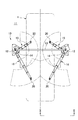
- FIG. 1 is a plan view showing a vehicle maintenance lift.
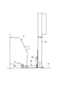
- FIG. 2 is a view taken along the line II-II in FIG.
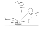
- FIG. 3 is a schematic diagram showing a use state of the lift point alignment apparatus.
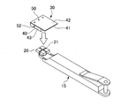
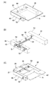
- FIG. 4 is a schematic perspective view showing the lifting arm and the lift point aligning device.
- 5A and 5B show a lift point aligning device
- FIG. 5A is an overall perspective view
- FIG. 5B is a schematic diagram showing an electric circuit of a light source built in the mirror body
- FIG. 5C is a structure for mounting the mirror body to a vehicle body support
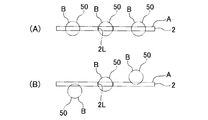
- It is a schematic diagram which shows. 6A and 6B show an image of a lift point and a light source image reflected on the mirror surface of the mirror body.
- FIG. 6A and 6B show an image of a lift point and a light source image reflected on the mirror surface of the mirror body.
- FIG. 6A and 6B show an image of a lift point and a light source image reflected on the
- FIG. 6A is a schematic diagram showing a matching state
- FIG. 6B is a schematic diagram showing a mismatching state
- 7A and 7B show a modification of the lift point aligning device.
- FIG. 7A is an overall perspective view
- FIG. 7B is a schematic diagram showing a structure for attaching a mirror body to a vehicle body support.
- the vehicle maintenance lift 10 has two support columns 12 and 12 erected on the left and right sides of the lift work area on the floor 11 of the maintenance site. Both struts 12 and 12 form a gate shape connected by a connecting beam 13.
- the vehicle maintenance lift 10 is provided with left and right lifting carriages 14 that can be lifted and lowered synchronously with each of the left and right support columns 12, and is supported by each lifting carriage 14 so as to be pivotable within a horizontal plane.
- An arm 15 and a long rear lifting arm 16 are provided.
- the front short elevating arm 15 includes a proximal arm, an intermediate arm, and a distal arm, and can be expanded and contracted in two short stages, and includes a body support 20 at the distal end of the distal arm.
- the rear long elevating arm 16 includes a proximal arm, an intermediate arm, and a distal arm, and can extend and contract in two major stages, and includes a vehicle body support 20 at the distal end of the distal arm.
- the swivel and expansion / contraction ranges in the horizontal plane of the elevating arms 15 and 16 are indicated by arcuate ranges in FIG.
- the vehicle maintenance lift 10 has a front short lifting arm 15 and a rear long lifting arm 16 provided on each of the left and right lifting carriages 14 pivoted and expanded in a horizontal plane, and each vehicle body support 20 provided at the tip thereof. To the lift points 2 provided at the front and rear two positions on the left side of the vehicle 1 and at the two front and rear positions on the right side. Thereafter, the lift arms 15 and 16 are raised in synchronization by operating the lift switch, so that the vehicle 1 can be lifted up and down horizontally.
- the lift point 2 provided in the lower part of the vehicle 1 consists of a linear side seal as shown in FIG.
- Each vehicle body support 20 provided at the tip of each lifting arm 15, 16 has a rectangular block shape made of, for example, hard rubber as shown in FIGS. 3 and 4, and has a linear shape (cross shape) on its upper surface. Groove-shaped vehicle body support portions 21 and 21 are provided. The vehicle body support portion 21 of the vehicle body support 20 is fitted into a side seal that is the lift point 2 at the bottom of the vehicle 1.
- the lift point aligning device 30 that matches the vehicle body receivers 20 provided at the tips of the lift arms 15 and 16 with the lift point 2 at the bottom of the vehicle 1 will be described in detail.
- the lift point aligning device 30 includes a mirror body 40 and a light source 50 as shown in FIG.
- the mirror body 40 is detachably attached to the vehicle body holder 20.
- the mirror body 40 includes a mirror plate 41, and the surface of the mirror plate 41 is a mirror surface 42. It is assumed that the mirror body 40 is disposed with the mirror surface 42 of the mirror surface plate 41 facing upward in a state of being attached to the vehicle body holder 20.
- the surface of the mirror surface plate 41 made of a stainless steel plate can be mirror-finished to obtain a mirror surface 42.
- the light source 50 is provided in the mirror body 40 and projects spot-like light in the vertical direction from the mirror surface 42 side of the mirror body 40 attached to the vehicle body support 20 toward the lower portion of the vehicle 1.
- the lift point aligning device 30 positions the image A of the lift point 2 of the vehicle 1 and the image B of the light source 50 that are reflected on the mirror surface 42 of the mirror body 40 on the side of the vehicle 1. Observe by worker M.
- the vehicle body with respect to the lift point 2 of the vehicle 1 based on the coincidence state of the image A of the lift point 2 reflected on the mirror surface 42 of the mirror body 40 and the image B of the light source 50 observed from the side of the vehicle 1 in this way.
- the matching state of the receiving tool 20 can be recognized.
- the vehicle body support portion 21 to be matched with the lift point 2 of the vehicle 1 is provided on the upper surface of the vehicle body support 20.
- the light source 50 provided in the mirror body 40 matches the vertical upper portion of the vehicle body support portion 21 of the vehicle body holder 20 with the mirror body 40 attached to the vehicle body holder 20. It is installed in the position to do.
- the vehicle body support portion 21 of the vehicle body support 20 forms a straight line (cross shape) that matches the straight lift point 2 (side seal) provided at the lower part of the vehicle 1. It is said that.
- the straight lift point 2 (side seal) provided at the lower part of the vehicle 1 clearly shows the lift center 2L of the side seal by notching it into a concave shape (FIG. 6).
- the lift point aligning device 30 is installed on a straight line in which a plurality of (three in this embodiment) light sources 50 match the linear vehicle body support portion 21 of the vehicle body support 20.
- One light source at the center of the three light sources 50 matches the center position of the linear vehicle body support portion 21 of the vehicle body support 20.
- the mounting frame portion 43 in which the mirror body 40 of the lift point aligning device 30 protrudes from two opposite sides (two left and right sides) on the back side of the mirror surface 41 is provided.
- each attachment frame portion 43 is received by the square block-shaped vehicle body receiver so that the two opposite side surfaces of the square block-like vehicle body holder 20 are sandwiched between the attachment frame portions 43. Attached to the outer periphery of the tool 20.
- the mirror body 40 of the lift point adjusting device 30 is mounted on the back side of the mirror surface 41 between the two mounting frame portions 43, 43 described above.
- the mounting projection 44 is provided so as to project orthogonally to 43.
- the attachment convex portion 44 is fitted to the groove-like vehicle body support portion 21 provided in the upper surface of the vehicle body holder 20 as shown in FIG.
- the mirror body 40 has a plurality of light sources 50 installed in a straight line due to the presence of the two mounting frame portions 43 and 44 and the above-described mounting convex portion 44 when mounted to the vehicle body holder 20. It is fixedly set so as to coincide with the vertical upper part of the linear vehicle body support portion 21 of the tool 20.
- the lift point aligning device 30 includes the light source 50 made of LEDs and includes three LEDs built in the mounting convex portion 44.
- the lift point aligning device 30 has a battery 51 such as a button-type battery for LEDs and a lighting switch 52 such as a push button built in the mounting frame portion 43.
- the electric circuit 53 which connects the light source 50, the battery 51, and the lighting switch 52 is incorporated in the mirror body 40 (attachment frame part 43 and attachment convex part 44).
- the battery 51 is hidden by a battery replacement lid 54 provided on the attachment frame portion 43, and the battery can be replaced by removing the lid 54.
- the battery 51 is fixed by a battery holder, and can be replaced without performing an electrical wiring process (disconnection or connection).
- the lighting switch 52 is assumed to perform an alternate operation. When the lighting switch 52 is pressed once, the LED is turned on, and when it is pressed again, the LED is turned off.
- the mirror body 40 of the lift point alignment device 30 with the light source 50 turned on is attached to the vehicle body holder 20 provided at the tip of the lift arms 15 and 16, and the vehicle body holder 20 of the lift arms 15 and 16 is attached to the vehicle 1.
- the vehicle body holder 20 of the lift arms 15 and 16 is attached to the vehicle 1.
- the worker M located on the side of the vehicle 1 displays the image A of the lower part of the vehicle 1 and the image B of the light source 50 projected on the lower part of the vehicle 1 reflected on the mirror surface 42 of the mirror body 40. It can be observed by reflection of the mirror surface 42. Thereby, the worker M moves the lifting arm so that the image B of the light source 50 reflected on the mirror surface 42 of the mirror body 40 coincides with the image A of the lift point 2 at the lower part of the vehicle 1 as shown in FIG.
- the front end positions of 15 and 16 can be adjusted so that the vehicle body support 20 matches the lift point 2 at the lower part of the vehicle 1.
- FIG. 6A shows the coincidence state between the image A of the lift point 2 and the image B of the light source 50.
- the image B of the three light sources 50 overlaps the image A of the linear lift point 2. This is a state where the position and orientation of the vehicle body support 20 match the lift point 2 of the vehicle 1.
- FIG. 6B shows a mismatch between the image A of the lift point 2 and the image B of the light source 50. Only the image B of only one light source 50 at the center of the three light sources 50 overlaps only the portion corresponding to the lift center portion 2L of the image A of the linear lift point 2. The center position of the vehicle body holder 20 is aligned with the lift center 2L of the lift point 2, but the direction of the vehicle body holder 20 is not aligned with the lift point 2.
- the position at which the image A of the lower part of the vehicle 1 and the image B of the light source 50 projected on the lower part of the vehicle 1 are reflected in the mirror surface 42 varies depending on the angular position at which the operator M views the mirror surface 42 of the mirror body 40.
- the light of the light source 50 is projected in the vertical direction toward the lower part of the vehicle 1, and the mutual position of the image A of the lower part of the vehicle 1 and the image B of the light source 50 projected on the lower part of the vehicle 1.
- the relationship does not change. Therefore, no matter where the operator M looks at the mirror surface 42 of the mirror body 40, the mutual position relationship between the image A of the lower part of the vehicle 1 and the image B of the light source 50 projected on the lower part of the vehicle 1 can be seen.
- the vehicle body support 20 can be matched with the lift point 2 at the bottom of the vehicle 1 as described above.
- the body 40 of the lift point aligning device 30 is removed from the vehicle body receiver 20 and the vehicle body receiver 20 of the lift arms 15 and 16 is raised in the vertical direction.
- the lift point 2 can be applied.
- the operator M does not need to look into the lower part of the dark vehicle 1 or take a tight working posture to lower his head in order to find the lift point 2 at the lower part of the vehicle 1.
- the lower lift point 2 can be adjusted.
- the light source 50 provided in the mirror body 40 is set to match the vehicle body support portion 21 of the vehicle body holder 20. Therefore, if the tip positions of the lift arms 15 and 16 are adjusted so that the image B of the light source 50 reflected on the mirror surface 42 of the mirror body 40 matches the image A of the lift point 2 at the lower part of the vehicle 1, the light source 50 matches the light source 50.
- the vehicle body support portion 21 of the vehicle body receiver 20 set so as to naturally match the lift point 2 at the lower part of the vehicle 1.
- the above-described mirror body 40 of (b) and (c) includes a mounting frame portion 43 protruding from the back side of the mirror surface 42, and when the mirror body 40 is mounted to the vehicle body holder 20, the mounting frame portion 43 is provided. Is attached to the outer periphery of the vehicle body support 20. Thereby, the attachment state of the mirror body 40 to the vehicle body holder 20 can be fixed, and the light source 50 provided on the mirror body 40 can be surely matched with the vehicle body support portion 21 of the vehicle body holder 20.
- the mirror body 40 of (b) to (d) described above includes a mounting convex portion 44 projecting from the back side of the mirror surface 42, and when the mirror body 40 is attached to the vehicle body holder 20, the mounting convex portion 44 is provided. Is fitted to a groove-like vehicle body support portion 21 provided in the upper surface of the vehicle body support 20. Thereby, the attachment state of the mirror body 40 to the vehicle body holder 20 can be fixed, and the light source 50 provided on the mirror body 40 is surely matched with the grooved vehicle body support portion 21 of the vehicle body holder 20. it can.
- the tip positions of the elevating arms 15 and 16 are adjusted so that the image B of the light source 50 reflected on the mirror surface 42 of the mirror body 40 matches the image A of the lift point 2 at the lower part of the vehicle 1, the light source 50 is surely matched.
- the groove-like vehicle body support portion 21 of the vehicle body receiver 20 set so as to stably match the lift point 2 at the lower portion of the vehicle 1.
- the light source 50 of the lift point aligning device 30 is formed of an LED, and the mirror body 40 includes a battery 51 for the LED and a lighting switch 52.
- the portable handling property of the lift point adjusting device 30 can be improved.
- FIG. 7 shows a modified example of the lift point aligning device 30.
- This modified example is different from the above-described embodiment in that the mirror body 40 protrudes from two opposite left and right sides of the mirror plate 41 as shown in FIG.
- the mounting frame portions 43 and 43 are provided, and the mounting frame portion 45 is provided on the front side on the back side of the specular plate 41. Then, when the mirror body 40 is attached to the vehicle body receiver 20, the attachment frame portions 43 and 45 are attached to three intersecting sides of the outer peripheral portion of the square block-shaped vehicle body receiver 20.
- the mirror body 40 has a plurality of light sources 50 installed in a straight line in a state where the mirror body 40 is attached to the vehicle body holder 20 and matches the vertical upper portion of the linear vehicle body support portion 21 of the vehicle body holder 20. Is set to be fixed.
- the mirror body 40 of the lift point aligning device 30 includes a connecting frame 46 that is orthogonal to the two mounting frame portions 43, 43 on the back side of the mirror plate 41.
- the connecting frame 46 of the mirror body 40 is set so as to coincide with the vertical upper portion of the vehicle body support portion 21 of the vehicle body holder 20 in a state where the mirror body 40 is attached to the vehicle body holder 20.
- the vehicle body support provided on the lifting arm is not limited to a square block shape, but may be a round disk shape.
- the vehicle body support is not limited to the one having a linear groove-shaped vehicle body support on the upper surface.
- the vehicle body support may include a hole-shaped vehicle body support portion at the center of the upper surface.
- the lift point of the vehicle is not limited to a linear shape such as a side seal but may be a surface shape.
- the mirror body of the lift point aligning device can be provided with a mounting portion on the back side of the mirror plate so as to be detachably engaged with the outer periphery of the vehicle body support and restrict free movement in the horizontal direction.
- the mirror surface of the mirror body is not limited to a mirror surface of a stainless steel plate.
- the light source is not limited to a spot shape but may be a line shape.
- the light source is not limited to LED, but may be laser light.
- the vehicle body support provided on the lift arm of the vehicle maintenance lift can be easily aligned with the lift point provided on the lower portion of the vehicle.
Landscapes
- Life Sciences & Earth Sciences (AREA)
- Engineering & Computer Science (AREA)
- Geology (AREA)
- Mechanical Engineering (AREA)
- Structural Engineering (AREA)
- Physics & Mathematics (AREA)
- General Physics & Mathematics (AREA)
- Vehicle Cleaning, Maintenance, Repair, Refitting, And Outriggers (AREA)
- Lighting Device Outwards From Vehicle And Optical Signal (AREA)
- Mirrors, Picture Frames, Photograph Stands, And Related Fastening Devices (AREA)
Abstract
Description
(a)光源を点灯させたリフトポイント合せ装置の鏡体を昇降アームの先端に設けた車体受具に取付け、この昇降アームの車体受具を車両の下部に挿入したとき、下記i、iiの通りになる。
(b)鏡体を車体受具に取付けた状態で、該鏡体に設けられる光源が、該車体受具の車体支持部に合致するように設定される。従って、鏡体の鏡面に映る光源の像が車両の下部のリフトポイントの像に一致するように昇降アームの先端位置を調整すれば、この光源に合致するように設定した車体受具の車体支持部が当然に車両の下部のリフトポイントに合致するものになる。
(c)上述(b)の車体受具の車体支持部が車両の直線状のリフトポイントに合致する直線状をなすとき、複数個の光源が該車体受具の直線状の車体支持部に合致する一直線上に設置されるものとする。従って、鏡体の鏡面に映る一直線上に設置された複数個の光源の像が車両の下部の直線状のリフトポイント(サイドシール等)の像に一致するように昇降アームの先端位置を平行移動、旋回移動して調整すれば、この複数個の光源が合致するように設定された車体受具の直線状の車体支持部が当該車両の下部の直線状のリフトポイントに合致するものになる。
(d)上述(b)、(c)の鏡体が鏡面の裏側に突設した取付枠部を備え、該鏡体の車体受具への取付け時に、該取付枠部を該車体受具の外周部に添設させるものとする。これにより、車体受具への鏡体の取付状態を固定化でき、鏡体に設けた光源を車体受具の車体支持部に確実に合致させるものとすることができる。
(e)上述(b)~(d)の鏡体が鏡面の裏側に突設した取付凸部を備え、該鏡体の車体受具への取付け時に、該取付凸部を該車体受具の上面内に設けた溝状車体支持部に嵌合させるものとする。これにより、車体受具への鏡体の取付状態を固定化でき、鏡体に設けた光源を車体受具の溝状車体支持部に確実に合致させるものとすることができる。鏡体の鏡面に映る光源の像が車両の下部のリフトポイントの像に一致するように昇降アームの先端位置を調整すれば、この光源に確実に合致するように設定された車体受具の溝状車体支持部が当然に車両の下部のリフトポイントに安定的に合致するものになる。
(f)リフトポイント合せ装置の前記光源がLEDからなり、前記鏡体がLEDのための電池、及び点灯スイッチを備える。リフトポイント合せ装置の携帯取扱い性を向上できる。
(a)光源50を点灯させたリフトポイント合せ装置30の鏡体40を昇降アーム15、16の先端に設けた車体受具20に取付け、この昇降アーム15、16の車体受具20を車両1の下部に挿入したとき、下記i、iiの通りになる。
2 リフトポイント
10 車両整備用リフト
15、16 昇降アーム
20 車体受具
21 溝状車体支持部
30 リフトポイント合せ装置
40 鏡体
42 鏡面
43 取付枠部
44 取付凸部
45 取付枠部
50 光源
51 電池
52 点灯スイッチ
Claims (6)
- 車両整備用リフトの昇降アームに設けた車体受具を、車両の下部に設けたリフトポイントに合せる車両整備用リフトのリフトポイント合せ装置であって、
車体受具に着脱可能に取付けられ、車体受具への取付状態で上向きとなる鏡面を備える鏡体と、
鏡体に設けられ、車体受具に取付けられた鏡体の鏡面の側から車両の下部に向かう鉛直方向に光を投射する光源とを有し、
車両の側方から観察される、鏡体の鏡面に映る車両の上記リフトポイントの像と光源の像との一致状態に基づいて、車両の上記リフトポイントに対する車体受具の合致状態を認識可能にする車両整備用リフトのリフトポイント合せ装置。 - 前記車体受具の上面に車両のリフトポイントに合致させるべき車体支持部を備えてなるとき、
鏡体を車体受具に取付けた状態で、該鏡体に設けられる光源が、該車体受具の車体支持部に合致するように設定されてなる請求項1に記載の車両整備用リフトのリフトポイント合せ装置。 - 前記車体受具の車体支持部が車両の直線状のリフトポイントに合致する直線状をなすとき、
複数個の光源が該車体受具の直線状の車体支持部に合致する一直線上に設置されてなる請求項2に記載の車両整備用リフトのリフトポイント合せ装置。 - 前記鏡体が鏡面の裏側に突設した取付枠部を備え、該鏡体の車体受具への取付け時に、該取付枠部を該車体受具の外周部に添設させてなる請求項2又は3に記載の車両整備用リフトのリフトポイント合せ装置。
- 前記鏡体が鏡面の裏側に突設した取付凸部を備え、該鏡体の車体受具への取付け時に、該取付凸部を該車体受具の上面内に設けた溝状車体支持部に嵌合させてなる請求項2~4のいずれかに記載の車両整備用リフトのリフトポイント合せ装置。
- 前記光源がLEDからなり、前記鏡体がLEDのための電池、及び点灯スイッチを備える請求項1~5のいずれかに記載の車両整備用リフトのリフトポイント合せ装置。
Priority Applications (4)
| Application Number | Priority Date | Filing Date | Title |
|---|---|---|---|
| US15/320,729 US10173873B2 (en) | 2014-07-15 | 2015-06-05 | Lift point alignment device for vehicle maintenance lifts |
| CN201580037132.4A CN106660766B (zh) | 2014-07-15 | 2015-06-05 | 车辆维修用升降机的升降点对准装置 |
| CA2952399A CA2952399C (en) | 2014-07-15 | 2015-06-05 | Lift point aligning device for vehicle maintenance lifts |
| EP15821339.7A EP3170785B1 (en) | 2014-07-15 | 2015-06-05 | Lift point aligning device for vehicle maintenance lifts |
Applications Claiming Priority (2)
| Application Number | Priority Date | Filing Date | Title |
|---|---|---|---|
| JP2014145364A JP5806368B1 (ja) | 2014-07-15 | 2014-07-15 | 車両整備用リフトのリフトポイント合せ装置 |
| JP2014-145364 | 2014-07-15 |
Publications (1)
| Publication Number | Publication Date |
|---|---|
| WO2016009744A1 true WO2016009744A1 (ja) | 2016-01-21 |
Family
ID=54545730
Family Applications (1)
| Application Number | Title | Priority Date | Filing Date |
|---|---|---|---|
| PCT/JP2015/066414 Ceased WO2016009744A1 (ja) | 2014-07-15 | 2015-06-05 | 車両整備用リフトのリフトポイント合せ装置 |
Country Status (6)
| Country | Link |
|---|---|
| US (1) | US10173873B2 (ja) |
| EP (1) | EP3170785B1 (ja) |
| JP (1) | JP5806368B1 (ja) |
| CN (1) | CN106660766B (ja) |
| CA (1) | CA2952399C (ja) |
| WO (1) | WO2016009744A1 (ja) |
Families Citing this family (6)
| Publication number | Priority date | Publication date | Assignee | Title |
|---|---|---|---|---|
| TWI617502B (zh) * | 2016-05-20 | 2018-03-11 | 明基三豐醫療器材股份有限公司 | 直線升降裝置 |
| US10195983B2 (en) | 2016-09-06 | 2019-02-05 | Ford Global Technologies, Llc | Motor vehicle jack positioning system and method |
| WO2020146803A2 (en) * | 2019-01-11 | 2020-07-16 | Fawley Bradford R | Lift pads with alignment functionality and methods of using the same |
| JP1642886S (ja) * | 2019-04-25 | 2019-10-07 | ||
| FR3100199B1 (fr) * | 2019-09-03 | 2022-11-18 | Laurens Frederic | Dispositif d’assistance au positionnement d’un objet sous un véhicule |
| WO2023178016A1 (en) * | 2022-03-15 | 2023-09-21 | BendPak, Inc. | Two post lift with reversible offset telescoping lift arms |
Citations (3)
| Publication number | Priority date | Publication date | Assignee | Title |
|---|---|---|---|---|
| JP2000238995A (ja) * | 1998-12-25 | 2000-09-05 | Sugiyasu Kogyo Kk | 自動車整備用リフトの車体支持装置 |
| JP2002128482A (ja) * | 2000-10-27 | 2002-05-09 | Banzai Ltd | 車両整備用2柱式リフト |
| JP2003081583A (ja) * | 2001-09-11 | 2003-03-19 | Sugiyasu Industries Co Ltd | 車輌整備用リフトのスイングアーム |
Family Cites Families (14)
| Publication number | Priority date | Publication date | Assignee | Title |
|---|---|---|---|---|
| US5309289A (en) * | 1991-03-11 | 1994-05-03 | Johnson Brady G | Optical target system for trailer hitch alignment |
| CN2221027Y (zh) | 1995-04-11 | 1996-02-28 | 李汉军 | 电动千斤顶 |
| US5947447A (en) * | 1997-01-29 | 1999-09-07 | Alltrade Inc. | Automotive service jack |
| US6076847A (en) * | 1998-08-26 | 2000-06-20 | Thornton; Morris E. | Trailer hitch alignment device |
| US20070216136A1 (en) * | 2006-03-15 | 2007-09-20 | Dietz Dan L | Single camera apparatus and methods for alignment of a trailer hitch |
| US8888121B2 (en) * | 2007-01-25 | 2014-11-18 | Target Hitch Llc | Towing vehicle guidance for trailer hitch connection |
| CN201301196Y (zh) | 2008-10-20 | 2009-09-02 | 安徽省广德中鼎汽车工具有限公司 | 带可视装置的千斤顶 |
| JP2011016618A (ja) * | 2009-07-08 | 2011-01-27 | Sugiyasu Corp | 車両整備用リフト |
| JP4961487B2 (ja) * | 2010-05-13 | 2012-06-27 | 本田技研工業株式会社 | 車両の後方確認装置 |
| US8220169B2 (en) * | 2010-09-11 | 2012-07-17 | Lawrence Auttlee Goddard | Method and system for guiding a plurality of load bearing members of a forklift |
| US9032633B2 (en) * | 2011-04-10 | 2015-05-19 | Steven C. Pittman | Method and apparatus for repositioning a tandem axle assembly of a trailer |
| US9085446B1 (en) * | 2012-07-31 | 2015-07-21 | Richard A. Dahs | Pivotable auto lift |
| WO2015194404A1 (ja) * | 2014-06-19 | 2015-12-23 | 株式会社ヤスヰ | 車両用リフト装置 |
| US9821849B2 (en) * | 2015-12-04 | 2017-11-21 | Bosch Automotive Service Solutions Llc | Wheel alignment and toe angle adjustment system for a three-wheeled vehicle |
-
2014
- 2014-07-15 JP JP2014145364A patent/JP5806368B1/ja active Active
-
2015
- 2015-06-05 CN CN201580037132.4A patent/CN106660766B/zh not_active Expired - Fee Related
- 2015-06-05 WO PCT/JP2015/066414 patent/WO2016009744A1/ja not_active Ceased
- 2015-06-05 US US15/320,729 patent/US10173873B2/en not_active Expired - Fee Related
- 2015-06-05 EP EP15821339.7A patent/EP3170785B1/en active Active
- 2015-06-05 CA CA2952399A patent/CA2952399C/en not_active Expired - Fee Related
Patent Citations (3)
| Publication number | Priority date | Publication date | Assignee | Title |
|---|---|---|---|---|
| JP2000238995A (ja) * | 1998-12-25 | 2000-09-05 | Sugiyasu Kogyo Kk | 自動車整備用リフトの車体支持装置 |
| JP2002128482A (ja) * | 2000-10-27 | 2002-05-09 | Banzai Ltd | 車両整備用2柱式リフト |
| JP2003081583A (ja) * | 2001-09-11 | 2003-03-19 | Sugiyasu Industries Co Ltd | 車輌整備用リフトのスイングアーム |
Non-Patent Citations (1)
| Title |
|---|
| See also references of EP3170785A4 * |
Also Published As
| Publication number | Publication date |
|---|---|
| JP2016020272A (ja) | 2016-02-04 |
| EP3170785A1 (en) | 2017-05-24 |
| CN106660766B (zh) | 2017-12-05 |
| CA2952399A1 (en) | 2016-01-21 |
| JP5806368B1 (ja) | 2015-11-10 |
| CN106660766A (zh) | 2017-05-10 |
| CA2952399C (en) | 2017-05-30 |
| EP3170785B1 (en) | 2019-09-11 |
| EP3170785A4 (en) | 2018-04-18 |
| US10173873B2 (en) | 2019-01-08 |
| US20180072544A1 (en) | 2018-03-15 |
Similar Documents
| Publication | Publication Date | Title |
|---|---|---|
| JP5806368B1 (ja) | 車両整備用リフトのリフトポイント合せ装置 | |
| JP5769412B2 (ja) | 構造物製造方法 | |
| US9885934B2 (en) | Portable defect mitigators for electrochromic windows | |
| CN203760047U (zh) | Amoled显示屏的otp装置及其定位机构 | |
| US9636824B2 (en) | Transfer system | |
| CN108406089A (zh) | 一种双光路激光打标设备及其打标方法 | |
| JP6998503B2 (ja) | 電子機器組立装置及び電子機器組立方法 | |
| JP2015168012A (ja) | 教示ジグ、教示システムおよび教示方法 | |
| TW201700245A (zh) | 刻劃裝置 | |
| CN108927422A (zh) | 整形机和天窗检测系统 | |
| JP5427566B2 (ja) | ロボット制御方法、ロボット制御プログラムおよびロボット制御方法に用いられるロボットハンド | |
| CN204241387U (zh) | 图像检测成像装置及图像检测设备 | |
| CN106077961A (zh) | 一种激光打标机 | |
| JP6280805B2 (ja) | ワーク形状測定システム及び制御方法 | |
| CN205414700U (zh) | 一种油杯焊接专机 | |
| CN212321472U (zh) | 一种玻璃面板的生产设备及其双相机检测系统 | |
| CN109079349A (zh) | 一种镜片切割装置及镜片切割方法 | |
| CN104815915B (zh) | 汽车零部件定位装置 | |
| CA2907555C (en) | Module placement device and method | |
| CN118809159B (zh) | 用于仪表盘组装的双工位对片装置 | |
| US10843345B2 (en) | Workpiece holding mechanism | |
| CN203843444U (zh) | 一种高压管道对接仪 | |
| JP6358619B2 (ja) | 車体の三次元位置測定方法及び三次元位置測定システム | |
| CN217099298U (zh) | 一种半自动ccd自动对位软对硬贴合机 | |
| CN213933065U (zh) | 一种灯具光照测试系统 |
Legal Events
| Date | Code | Title | Description |
|---|---|---|---|
| 121 | Ep: the epo has been informed by wipo that ep was designated in this application |
Ref document number: 15821339 Country of ref document: EP Kind code of ref document: A1 |
|
| ENP | Entry into the national phase |
Ref document number: 2952399 Country of ref document: CA |
|
| REEP | Request for entry into the european phase |
Ref document number: 2015821339 Country of ref document: EP |
|
| WWE | Wipo information: entry into national phase |
Ref document number: 15320729 Country of ref document: US Ref document number: 2015821339 Country of ref document: EP |
|
| NENP | Non-entry into the national phase |
Ref country code: DE |