WO2016009905A1 - ブレーキ装置 - Google Patents
ブレーキ装置 Download PDFInfo
- Publication number
- WO2016009905A1 WO2016009905A1 PCT/JP2015/069563 JP2015069563W WO2016009905A1 WO 2016009905 A1 WO2016009905 A1 WO 2016009905A1 JP 2015069563 W JP2015069563 W JP 2015069563W WO 2016009905 A1 WO2016009905 A1 WO 2016009905A1
- Authority
- WO
- WIPO (PCT)
- Prior art keywords
- brake
- brake device
- lever
- actuator
- eccentric
- Prior art date
- Legal status (The legal status is an assumption and is not a legal conclusion. Google has not performed a legal analysis and makes no representation as to the accuracy of the status listed.)
- Ceased
Links
Images
Classifications
-
- B—PERFORMING OPERATIONS; TRANSPORTING
- B61—RAILWAYS
- B61H—BRAKES OR OTHER RETARDING DEVICES SPECIALLY ADAPTED FOR RAIL VEHICLES; ARRANGEMENT OR DISPOSITION THEREOF IN RAIL VEHICLES
- B61H5/00—Applications or arrangements of brakes with substantially radial braking surfaces pressed together in axial direction, e.g. disc brakes
-
- F—MECHANICAL ENGINEERING; LIGHTING; HEATING; WEAPONS; BLASTING
- F16—ENGINEERING ELEMENTS AND UNITS; GENERAL MEASURES FOR PRODUCING AND MAINTAINING EFFECTIVE FUNCTIONING OF MACHINES OR INSTALLATIONS; THERMAL INSULATION IN GENERAL
- F16D—COUPLINGS FOR TRANSMITTING ROTATION; CLUTCHES; BRAKES
- F16D55/00—Brakes with substantially-radial braking surfaces pressed together in axial direction, e.g. disc brakes
- F16D55/02—Brakes with substantially-radial braking surfaces pressed together in axial direction, e.g. disc brakes with axially-movable discs or pads pressed against axially-located rotating members
- F16D55/22—Brakes with substantially-radial braking surfaces pressed together in axial direction, e.g. disc brakes with axially-movable discs or pads pressed against axially-located rotating members by clamping an axially-located rotating disc between movable braking members, e.g. movable brake discs or brake pads
- F16D55/224—Brakes with substantially-radial braking surfaces pressed together in axial direction, e.g. disc brakes with axially-movable discs or pads pressed against axially-located rotating members by clamping an axially-located rotating disc between movable braking members, e.g. movable brake discs or brake pads with a common actuating member for the braking members
- F16D55/225—Brakes with substantially-radial braking surfaces pressed together in axial direction, e.g. disc brakes with axially-movable discs or pads pressed against axially-located rotating members by clamping an axially-located rotating disc between movable braking members, e.g. movable brake discs or brake pads with a common actuating member for the braking members the braking members being brake pads
- F16D55/2255—Brakes with substantially-radial braking surfaces pressed together in axial direction, e.g. disc brakes with axially-movable discs or pads pressed against axially-located rotating members by clamping an axially-located rotating disc between movable braking members, e.g. movable brake discs or brake pads with a common actuating member for the braking members the braking members being brake pads in which the common actuating member is pivoted
-
- F—MECHANICAL ENGINEERING; LIGHTING; HEATING; WEAPONS; BLASTING
- F16—ENGINEERING ELEMENTS AND UNITS; GENERAL MEASURES FOR PRODUCING AND MAINTAINING EFFECTIVE FUNCTIONING OF MACHINES OR INSTALLATIONS; THERMAL INSULATION IN GENERAL
- F16D—COUPLINGS FOR TRANSMITTING ROTATION; CLUTCHES; BRAKES
- F16D65/00—Parts or details
- F16D65/14—Actuating mechanisms for brakes; Means for initiating operation at a predetermined position
- F16D65/16—Actuating mechanisms for brakes; Means for initiating operation at a predetermined position arranged in or on the brake
- F16D65/18—Actuating mechanisms for brakes; Means for initiating operation at a predetermined position arranged in or on the brake adapted for drawing members together, e.g. for disc brakes
- F16D65/183—Actuating mechanisms for brakes; Means for initiating operation at a predetermined position arranged in or on the brake adapted for drawing members together, e.g. for disc brakes with force-transmitting members arranged side by side acting on a spot type force-applying member
-
- F—MECHANICAL ENGINEERING; LIGHTING; HEATING; WEAPONS; BLASTING
- F16—ENGINEERING ELEMENTS AND UNITS; GENERAL MEASURES FOR PRODUCING AND MAINTAINING EFFECTIVE FUNCTIONING OF MACHINES OR INSTALLATIONS; THERMAL INSULATION IN GENERAL
- F16D—COUPLINGS FOR TRANSMITTING ROTATION; CLUTCHES; BRAKES
- F16D65/00—Parts or details
- F16D65/38—Slack adjusters
- F16D65/40—Slack adjusters mechanical
- F16D65/42—Slack adjusters mechanical non-automatic
- F16D65/44—Slack adjusters mechanical non-automatic by means of direct linear adjustment
-
- F—MECHANICAL ENGINEERING; LIGHTING; HEATING; WEAPONS; BLASTING
- F16—ENGINEERING ELEMENTS AND UNITS; GENERAL MEASURES FOR PRODUCING AND MAINTAINING EFFECTIVE FUNCTIONING OF MACHINES OR INSTALLATIONS; THERMAL INSULATION IN GENERAL
- F16D—COUPLINGS FOR TRANSMITTING ROTATION; CLUTCHES; BRAKES
- F16D2121/00—Type of actuator operation force
- F16D2121/02—Fluid pressure
-
- F—MECHANICAL ENGINEERING; LIGHTING; HEATING; WEAPONS; BLASTING
- F16—ENGINEERING ELEMENTS AND UNITS; GENERAL MEASURES FOR PRODUCING AND MAINTAINING EFFECTIVE FUNCTIONING OF MACHINES OR INSTALLATIONS; THERMAL INSULATION IN GENERAL
- F16D—COUPLINGS FOR TRANSMITTING ROTATION; CLUTCHES; BRAKES
- F16D2125/00—Components of actuators
- F16D2125/18—Mechanical mechanisms
- F16D2125/20—Mechanical mechanisms converting rotation to linear movement or vice versa
- F16D2125/22—Mechanical mechanisms converting rotation to linear movement or vice versa acting transversely to the axis of rotation
- F16D2125/28—Cams; Levers with cams
- F16D2125/32—Cams; Levers with cams acting on one cam follower
-
- F—MECHANICAL ENGINEERING; LIGHTING; HEATING; WEAPONS; BLASTING
- F16—ENGINEERING ELEMENTS AND UNITS; GENERAL MEASURES FOR PRODUCING AND MAINTAINING EFFECTIVE FUNCTIONING OF MACHINES OR INSTALLATIONS; THERMAL INSULATION IN GENERAL
- F16D—COUPLINGS FOR TRANSMITTING ROTATION; CLUTCHES; BRAKES
- F16D2125/00—Components of actuators
- F16D2125/18—Mechanical mechanisms
- F16D2125/58—Mechanical mechanisms transmitting linear movement
- F16D2125/64—Levers
-
- F—MECHANICAL ENGINEERING; LIGHTING; HEATING; WEAPONS; BLASTING
- F16—ENGINEERING ELEMENTS AND UNITS; GENERAL MEASURES FOR PRODUCING AND MAINTAINING EFFECTIVE FUNCTIONING OF MACHINES OR INSTALLATIONS; THERMAL INSULATION IN GENERAL
- F16D—COUPLINGS FOR TRANSMITTING ROTATION; CLUTCHES; BRAKES
- F16D2125/00—Components of actuators
- F16D2125/18—Mechanical mechanisms
- F16D2125/58—Mechanical mechanisms transmitting linear movement
- F16D2125/68—Lever-link mechanisms, e.g. toggles with change of force ratio
-
- F—MECHANICAL ENGINEERING; LIGHTING; HEATING; WEAPONS; BLASTING
- F16—ENGINEERING ELEMENTS AND UNITS; GENERAL MEASURES FOR PRODUCING AND MAINTAINING EFFECTIVE FUNCTIONING OF MACHINES OR INSTALLATIONS; THERMAL INSULATION IN GENERAL
- F16D—COUPLINGS FOR TRANSMITTING ROTATION; CLUTCHES; BRAKES
- F16D55/00—Brakes with substantially-radial braking surfaces pressed together in axial direction, e.g. disc brakes
- F16D55/02—Brakes with substantially-radial braking surfaces pressed together in axial direction, e.g. disc brakes with axially-movable discs or pads pressed against axially-located rotating members
- F16D55/22—Brakes with substantially-radial braking surfaces pressed together in axial direction, e.g. disc brakes with axially-movable discs or pads pressed against axially-located rotating members by clamping an axially-located rotating disc between movable braking members, e.g. movable brake discs or brake pads
- F16D55/224—Brakes with substantially-radial braking surfaces pressed together in axial direction, e.g. disc brakes with axially-movable discs or pads pressed against axially-located rotating members by clamping an axially-located rotating disc between movable braking members, e.g. movable brake discs or brake pads with a common actuating member for the braking members
- F16D55/2245—Brakes with substantially-radial braking surfaces pressed together in axial direction, e.g. disc brakes with axially-movable discs or pads pressed against axially-located rotating members by clamping an axially-located rotating disc between movable braking members, e.g. movable brake discs or brake pads with a common actuating member for the braking members in which the common actuating member acts on two levers carrying the braking members, e.g. tong-type brakes
Definitions
- the present invention relates to a brake device.
- the force of an actuator is applied to the force point of a pair of link arms that can rotate around a fulcrum, and the brake lining supported by the point of action of the link arm is brought into sliding contact with the brake disc to brake the rotation of the wheel.
- a brake device is used.
- JP10-505038A one end of a caliper lever is connected to each other, and the other end is pivotally attached to each brake pad.
- An eccentric transmission device provided at a fulcrum between both ends of the caliper lever includes a caliper lever.
- a brake caliper unit that pivots is disclosed.
- the eccentric body transmission device has an eccentric pin that rotates in response to a force generated by a brake force generator, and rotates the caliper lever around one end by the rotation of the eccentric pin.
- This invention aims at improving the mechanical efficiency of a brake device.
- a pair of link arms that support a brake lining that is rotatably supported and is provided on both sides of the brake disc, and the other end portion is in sliding contact with the brake disc to apply a frictional force.
- a connecting member that connects the one end portions of the pair of link arms, an actuator that is attached to the connecting member and moves the output member back and forth, and is rotatably connected to the output member of the actuator.
- a lever that is rotated by advancing and retreating, and at least one of the one end portions of the pair of link arms. The force transmitted by the turning and booster and a booster unit which rotates the link arm to pivot the support portion.
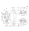
- FIG. 1 is a plan view of a brake device according to an embodiment of the present invention.
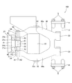
- FIG. 2 is a front view of the brake device according to the embodiment of the present invention.
- the brake device 100 is mainly applied to a railway vehicle.
- the brake device 100 brakes the wheel 1 by sandwiching a brake disc 1 a that rotates together with the wheel 1. Specifically, the brake device 100 sandwiches the brake disc 1a from both sides with a pair of brake linings 2, and brakes the rotation of the wheel 1 by the frictional force between the brake disc 1a and the brake lining 2.
- the brake disc 1a is formed on both front and back surfaces of the wheel 1 and rotates integrally with the wheel 1. Instead of the structure in which the brake disk 1a is formed integrally with the wheel 1, a separate brake disk 1a that rotates together with the wheel 1 may be provided.
- the brake lining 2 is opposed to the brake disk 1a with a predetermined interval (state shown in FIG. 1) when not braking. During braking, the brake lining 2 moves toward the brake disc 1a and is pressed against the brake disc 1a in parallel.
- the brake lining 2 includes a back plate portion 2a supported by the lining holding portion 3 of the brake device 100, and a friction member 2b that contacts the brake disc 1a during braking.
- the friction member 2b includes a plurality of segments and is fixed to the surface of the back plate portion 2a. The brake lining 2 brakes the rotation of the wheel 1 by the frictional force generated by the contact between the friction member 2b and the brake disc 1a.
- the lining holding part 3 has a dovetail groove (not shown) into which the back plate part 2a of the brake lining 2 is inserted.
- Anchor blocks 4 that are fixed to the lining holder 3 by a pair of anchor bolts 5 are respectively provided at the upper and lower ends of the lining holder 3.
- the anchor block 4 fixes the end of the back plate portion 2a of the brake lining 2 in the longitudinal direction (vertical direction in FIG. 2). Thereby, the brake lining 2 inserted in the dovetail is held by the lining holding part 3.
- the brake device 100 includes a brake main body 10, a pair of link arms 30 on which a support portion 32 between one end 31 and the other end 33 is rotatably supported with respect to the brake main body 10, and a pair of link arms.
- a connecting rod 35 as a connecting member for connecting the one end portions 31 of 30, an actuator 20 attached to the connecting rod 35 and moving the rod 21 as an output member back and forth, and a rod 21 of the actuator 20 so as to be rotatable.
- the lever 40 Provided on at least one of the lever 40 that rotates by the advancement and retraction of the rod 21 and the one end 31 of the pair of link arms 30, the force transmitted by the rotation of the lever 40 is boosted and the support 32 is used as a fulcrum.
- a booster unit 50 for rotating the link arm 30.
- the brake body 10 is supported by a carriage (not shown) when the brake device 100 is applied to a railway vehicle.
- the brake body 10 is supported by a vehicle body (not shown) when the brake device 100 is applied to a vehicle other than a railway vehicle.
- Actuator 20 is a fluid pressure actuator that operates by the pressure of a working fluid such as hydraulic pressure such as hydraulic pressure or pneumatic pressure.
- the actuator 20 is not limited to this, and may be another type such as a mechanical actuator that operates by rotation of an electric motor.
- the actuator 20 operates based on the driver's braking operation, and moves the rod 21 forward and backward with respect to the actuator body 20 a attached to the connecting rod 35.
- the actuator 20 is provided at a position farther from the support portion 32 than the one end portion 31 of the link arm 30. That is, the actuator 20 is provided to face the brake body 10 with the connecting rod 35 interposed therebetween. Thereby, since the actuator 20 is provided outside the region surrounded by the connecting rod 35 and the pair of link arms 30, the design freedom of the link arm 30 is improved. Therefore, since the link arm 30 can be shortened, the brake device 100 can be reduced in size and weight.
- the rod 21 is formed in a U shape having a connecting portion 21a connected to each of the pair of levers 40 and a recess 21b formed between the pair of connecting portions 21a.
- the recess 21b prevents interference between the rod 21 and the connecting rod 35 when the rod 21 is withdrawn from the actuator body 20a. Therefore, when the rod 21 retreats from the actuator main body 20a, the connecting rod 35 enters the recess 21b, and the pair of connecting portions 21a extend away from the connecting rod 35.
- the rod 21 has a pair of connecting shafts 22 for connecting the levers 40 to the respective connecting portions 21a in a rotatable manner (see FIG. 1).
- the pair of connecting shafts 22 are provided coaxially.
- the connecting shaft 22 is arranged so that the central axis thereof is parallel to the brake lining 2.
- the center of the brake disc 1a is located on the extension line of the central axis along which the rod 21 reciprocates.
- the rod 21 advances and retreats with respect to the actuator body 20a, and can swing in a direction in which the brake lining 2 can move (vertical direction in FIG. 1).
- the link arms 30 are respectively provided facing both surfaces of the brake disc 1a.
- One end portions 31 of the pair of link arms 30 are connected by a connecting rod 35.
- the other end portion 33 of the link arm 30 supports the brake lining 2 slidably in contact with the brake disc 1a to apply a frictional force so as to be swingable.
- the link arm 30 is formed in a substantially U shape having a pair of arm portions 30a provided on the top and bottom.
- one end 31 of one link arm 30 is provided with a connecting shaft 31 a that penetrates and connects the connecting rod 35 and the link arm 30.
- One end 31 of the other link arm 30 is connected through the connecting rod 35, the link arm 30, and the pair of levers 40, and the force generated by the advancement / retraction of the rod 21 of the actuator 20 is boosted to link arm 30. Is provided.
- a booster unit 50 may be provided at one end 31 of one link arm 30 and one end 31 of the other link arm 30. In that case, each booster unit 50 can rotate one link arm 30 and the other link arm 30, respectively.
- the booster unit 50 will be described later in detail.
- the support portion 32 of the link arm 30 is provided with an arm shaft 32 a that penetrates and connects the link arm 30 and the brake body 10.
- the link arm 30 is rotatably supported by the brake body 10 by an arm shaft 32a.
- a circumferential tangential force acting on the brake lining 2 from the brake disc 1a during braking of the brake device 100 acts on the brake body 10 from the support portion 32 via the arm shaft 32a.
- the other end portion 33 of the link arm 30 is provided with a lining shaft 33 a that penetrates and connects the link arm 30 and the lining holding portion 3.
- the lining holding part 3 is rotatably supported by the link arm 30 by the lining shaft 33a.
- the lever 40 transmits the force generated by the advancement / retraction of the rod 21 of the actuator 20 to the booster unit 50.
- One end 41 of the lever 40 is rotatably connected to the connecting shaft 22 of the rod 21.
- the other end portion 42 of the lever 40 is non-rotatably connected to an eccentric portion 53 described later of the booster unit 50.
- the lever 40 rotates between the connecting shaft 22 and the eccentric portion 53 when the rod 21 advances and retreats with respect to the actuator body 20a.
- the lever 40 rotates to a position parallel to the connecting rod 35 in a state where the rod 21 is most retracted from the actuator body 20a.
- the booster unit 50 has an eccentric cam 51 that rotates about the rotation axis A ⁇ b> 1 by the rotation of the lever 40.
- the rotational axis A1 of the eccentric cam 51 is provided such that the position with respect to the link arm 30 is the same position as the central axis of the connecting shaft 31a.
- the eccentric cam 51 has a large-diameter portion 52 that is rotatably connected to the connecting rod 35, a center axis A2 at a position offset from the rotation axis A1 of the eccentric cam 51, and a rotation axis A1 by rotation of the lever 40. And a pair of arm connecting portions 54 formed coaxially with the eccentric portion 53 and rotatably supported by the link arm 30.
- the large diameter portion 52 is formed to have the same outer diameter as the connecting shaft 31a.
- the central axis of the large-diameter portion 52 is the rotation axis A1 of the eccentric cam 51.
- the eccentric portion 53 is formed to have a smaller diameter than the large diameter portion 52.
- the eccentric portions 53 are provided on both sides of the large diameter portion 52 in the axial direction.
- the lever 40 is connected to the eccentric portion 53 so as not to be relatively rotatable. Therefore, when the rod 21 advances and retreats with respect to the actuator main body 20a and the lever 40 rotates, the eccentric portion 53 rotates in an arc shape centering on the rotation axis A1.
- the arm connecting portion 54 is formed to have the same diameter as the eccentric portion 53.
- the arm connecting portion 54 is provided on the opposite side of the large diameter portion 52 with the eccentric portion 53 interposed therebetween. Instead of this, the arm connecting portion 54 may be formed with a smaller diameter than the eccentric portion 53. Further, the arm connecting portion 54 may be provided between the eccentric portion 53 and the large diameter portion 52.
- the eccentric cam 51 has the large-diameter portion 52 at the center, the eccentric portions 53 smaller in diameter than the large-diameter portion 52 at both ends, and the same diameter or eccentric portion as the eccentric portion 53 at both ends.
- An arm connecting portion 54 having a smaller diameter than 53 is provided. Therefore, since the eccentric cam 51 is gradually reduced in diameter from the center toward both ends, it is easy to process. Moreover, since the connecting rod 35, the lever 40, and the link arm 30 can be assembled to the eccentric cam 51 in order, the assemblability is good.
- the brake device 100 further includes an adjuster 37 that extends the connecting rod 35 in accordance with the wear amount of the brake lining 2.
- the adjuster 37 is provided outside the range where the actuator 20 is attached.
- the adjuster 37 extends the connecting rod 35 by extending the adjustment rod 36.
- the adjuster 37 rotates an adjusting screw (not shown) provided in the connecting rod 35 to extend the adjusting rod 36.
- the adjuster 37 is provided outside the range where the actuator 20 of the connecting rod 35 is attached, the positional relationship between the actuator 20 and the booster unit 50 even if the brake lining 2 is worn and the connecting rod 35 extends. Does not change. Therefore, even if the brake lining 2 is worn, it is possible not to change the operating characteristics of the actuator 20.
- the brake device 100 changes from the non-braking state (the state shown in FIGS. 1 and 2) to the braking state.
- the eccentric cam 51 rotates in one direction (clockwise in FIG. 1) when the eccentric portion 53 rotates in an arc shape around the rotation axis A1 by the force transmitted through the lever 40.
- the arm connecting portion 54 rotates together with the eccentric portion 53 in a direction away from the rod 21, so that the one end portions 31 of the pair of link arms 30 move in directions away from each other.
- the link arm 30 is rotatably supported by the brake body 10 by the support portion 32, when the one end portion 31 moves in a direction away from each other, the other end portion 33 moves in a direction close to each other. Therefore, the brake lining 2 moves toward the brake disc 1a and is pressed in contact with the brake disc 1a in parallel, so that the rotation of the wheel 1 is braked.
- the eccentric cam 51 has a lever ratio between a distance L1 between the central axis A3 of the connecting shaft 22 and the rotational axis A1 and a distance L2 between the rotational axis A1 and the central axis A2 of the eccentric portion 53.
- the force transmitted from the rod 21 via the lever 40 is doubled by L1 / L2 and transmitted to the link arm 30. Therefore, a large braking force can be obtained without providing a large actuator. Therefore, the brake device 100 can be reduced in size and weight.
- the link arm 30 is supported such that the support portion 32 between the one end portion 31 and the other end portion 33 is rotatable with respect to the brake body 10.
- An eccentric cam 51 that rotates the link arm 30 by boosting the force transmitted to the rod 21 by the rotation of the lever 40 is provided at one end 31 of the link arm 30. Therefore, the circumferential tangential force that acts on the brake lining 2 from the brake disc 1 a during braking of the brake device 100 acts on the arm shaft 32 a of the support portion 32 and does not act on the eccentric cam 51. Therefore, since the frictional resistance when the eccentric cam 51 rotates does not increase, the mechanical efficiency during braking of the brake device 100 can be improved.
- the force transmitted from the eccentric cam 51 to the one end portion 31 of the link arm 30 is a lever of a distance L3 between the one end portion 31 and the support portion 32 and a distance L4 between the support portion 32 and the other end portion 33. Depending on the ratio, it is boosted to L3 / L4 times. In the brake device 100, since the distance L4 is larger than the distance L3, the force that presses the brake lining 2 against the brake disc 1a is larger than the force transmitted from the eccentric cam 51 to the one end 31 of the link arm 30. It becomes a small force.
- the force transmitted from the rod 21 of the actuator 20 via the lever 40 by the eccentric cam 51 is boosted at a large magnification. Therefore, even if the link arm 30 is shortened and the distance L3 is reduced in order to reduce the size and weight of the brake device 100, a sufficiently large braking force can be obtained.
- the eccentric cam 51 is provided at the one end 31 of the link arm 30, so that the design freedom of the position of the arm shaft 32 a of the support portion 32 is increased. Therefore, it is possible to arrange the arm shaft 32 a at a position facing the side surface of the wheel 1. Therefore, the distance L3 can be made larger than the distance L4, and the force boosted by the eccentric cam 51 can be further boosted to press the brake lining 2 against the brake disc 1a.
- Brake device 100 changes from a braking state to a non-braking state (the state shown in FIGS. 1 and 2) when actuator 20 operates in the direction opposite to that during braking based on a driver's braking release operation.
- the eccentric cam 51 rotates in the other direction (counterclockwise in FIG. 1) when the eccentric portion 53 rotates in an arc shape around the rotation axis A1 by the force transmitted through the lever 40.
- the one end part 31 of a pair of link arm 30 moves to the direction which adjoins mutually.
- the other end portions 33 of the pair of link arms 30 move in directions away from each other.
- the brake lining 2 is separated from the brake disc 1a, and the braking of the wheel 1 is released.
- the link arm 30 is supported such that a support portion 32 between one end portion 31 and the other end portion 33 is rotatable with respect to the brake body 10.
- An eccentric cam 51 that rotates the link arm 30 by boosting the force transmitted to the rod 21 by the rotation of the lever 40 is provided at one end 31 of the link arm 30. Therefore, the circumferential tangential force that acts on the brake lining 2 from the brake disc 1 a during braking of the brake device 100 acts on the arm shaft 32 a of the support portion 32 and does not act on the eccentric cam 51. Therefore, since the frictional resistance when the eccentric cam 51 rotates does not increase, the mechanical efficiency during braking of the brake device 100 can be improved.
- a brake device 100 that clamps and brakes a brake disc 1a that rotates with a wheel 1 includes a brake body 10 supported by a vehicle body or a carriage, and one end 31 and the other end 33 with respect to the brake body 10.
- a support portion 32 is rotatably supported and provided on both sides of the brake disc 1a, and the other end portion 33 supports the brake lining 2 that slides against the brake disc 1a and applies a frictional force.
- a pair of link arms 30, a connecting rod 35 that connects one end portions 31 of the pair of link arms 30, an actuator 20 that is attached to the connecting rod 35 and moves the rod 21 forward and backward, and can be rotated by the rod 21 of the actuator 20.
- the lever 40 that is connected to the rod 21 and rotates by the advancement and retraction of the rod 21, and one end 31 of the pair of link arms 30.
- Provided on at least one Chi characterized in that it comprises a booster unit 50 to rotate the link arm 30 to boost the forces transmitted by the rotation of the lever 40 to pivot the support portion 32, a.
- the link arm 30 is supported such that the support portion 32 between the one end portion 31 and the other end portion 33 is rotatable with respect to the brake body 10.
- An eccentric cam 51 that rotates the link arm 30 by boosting the force transmitted to the rod 21 by the rotation of the lever 40 is provided at one end 31 of the link arm 30. Therefore, the circumferential tangential force that acts on the brake lining 2 from the brake disc 1 a during braking of the brake device 100 acts on the arm shaft 32 a of the support portion 32 and does not act on the eccentric cam 51. Therefore, since the frictional resistance when the eccentric cam 51 rotates does not increase, the mechanical efficiency during braking of the brake device 100 can be improved.
- the connecting rod 35 is further provided with an adjuster 37 provided outside the range where the actuator 20 is attached and extending the connecting rod 35 according to the amount of wear of the brake lining 2.
- the actuator 20 is provided at a position farther from the support portion 32 than the one end portion 31 of the link arm 30.
- the actuator 20 is provided outside the area surrounded by the connecting rod 35 and the pair of link arms 30, the design freedom of the link arm 30 is improved. Therefore, since the link arm 30 can be shortened, the brake device 100 can be reduced in size and weight.
- the booster unit 50 has an eccentric cam 51 that rotates about the rotation axis A1 by the rotation of the lever 40, and the eccentric cam 51 is centered at a position offset from the rotation axis A1. It has the eccentric part 53 which has A2 and rotates in circular arc shape centering on rotating shaft A1 by rotation of the lever 40, It is characterized by the above-mentioned.
- the eccentric cam 51 further includes a large-diameter portion 52 that is rotatably connected to the connecting rod 35, and the eccentric portion 53 is formed with a smaller diameter than the large-diameter portion 52,
- the levers 40 are respectively provided on both sides in the axial direction of the large-diameter portion 52 and are connected so as not to be relatively rotatable.
- the eccentric cam 51 is formed on the opposite side of the large-diameter portion 52 with the eccentric portion 53 interposed therebetween or between the eccentric portion 53 and the large-diameter portion 52 and coaxially with the eccentric portion 53.
- 30 further includes a pair of arm connecting portions 54 that are rotatably supported by 30.
- the eccentric cam 51 is inserted from the rod 21 through the lever 40 according to the lever ratio between the distance between both ends of the lever 40 and the distance from the rotation axis A1 to the central axis A3 of the eccentric portion 53.
- the transmitted force is boosted and transmitted to the link arm 30. Therefore, a large braking force can be obtained without providing a large actuator. Therefore, the brake device 100 can be reduced in size and weight.
- the actuator 20 is provided outside the region surrounded by the connecting rod 35 and the pair of link arms 30.
- the present invention is not limited to this, and it is only necessary that the actuator 20 be attached to the connecting rod 35. Therefore, the actuator 20 may be provided inside a region surrounded by the connecting rod 35 and the pair of link arms 30.
- the rod 21 and the lever 40 of the actuator 20 may be covered with a cover member (not shown) attached to the connecting rod 35. Thereby, the rod 21 and the lever 40 which operate when the brake device 100 is operated can be protected.
Landscapes
- Engineering & Computer Science (AREA)
- General Engineering & Computer Science (AREA)
- Mechanical Engineering (AREA)
- Braking Arrangements (AREA)
Abstract
Description
Claims (6)
- 車輪とともに回転するブレーキディスクを挟持して制動するブレーキ装置であって、
車体又は台車に支持されるブレーキ本体と、
前記ブレーキ本体に対して一端部と他端部との間の支持部が回動可能に支持されて前記ブレーキディスクの両面に臨んで各々設けられ、前記他端部が前記ブレーキディスクに摺接して摩擦力を付与するブレーキライニングを支持する一対のリンクアームと、
前記一対のリンクアームの前記一端部どうしを連結する連結部材と、
前記連結部材に取り付けられ、出力部材を進退させるアクチュエータと、
前記アクチュエータの前記出力部材に回動可能に連結され前記出力部材の進退によって回動するレバーと、
前記一対のリンクアームの前記一端部のうち少なくとも一方に設けられ、前記レバーの回動によって伝達される力を倍力して前記支持部を支点に前記リンクアームを回動させる倍力ユニットと、を備えるブレーキ装置。 - 請求項1に記載のブレーキ装置であって、
前記連結部材の前記アクチュエータが取り付けられる範囲外に設けられ、前記ブレーキライニングの摩耗量に応じて前記連結部材を伸長させるアジャスタを更に備えるブレーキ装置。 - 請求項1に記載のブレーキ装置であって、
前記アクチュエータは、前記リンクアームの前記一端部よりも前記支持部から離れた位置に設けられるブレーキ装置。 - 請求項1に記載のブレーキ装置であって、
前記倍力ユニットは、前記レバーの回動によって回転軸を中心に回転する偏心カムを有し、
前記偏心カムは、前記回転軸からオフセットされた位置に中心軸を有し前記レバーの回動によって前記回転軸を中心として円弧状に回動する偏心部を有するブレーキ装置。 - 請求項4に記載のブレーキ装置であって、
前記偏心カムは、
前記連結部材に回動可能に連結される大径部を更に有し、
前記偏心部は、前記大径部と比較して小径に形成され、前記大径部の軸方向両側に各々設けられて前記レバーが相対回動不能に連結されるブレーキ装置。 - 請求項5に記載のブレーキ装置であって、
前記偏心カムは、前記偏心部を挟んで前記大径部の反対側に又は前記偏心部と前記大径部との間に、前記偏心部と同軸に形成され前記リンクアームに回転可能に支持される一対のアーム連結部を更に有するブレーキ装置。
Priority Applications (4)
| Application Number | Priority Date | Filing Date | Title |
|---|---|---|---|
| US15/031,014 US9815484B2 (en) | 2014-07-18 | 2015-07-07 | Brake apparatus |
| EP15821971.7A EP3045760B1 (en) | 2014-07-18 | 2015-07-07 | Brake apparatus |
| KR1020167010593A KR20160060710A (ko) | 2014-07-18 | 2015-07-07 | 브레이크 장치 |
| CN201580002221.5A CN105683608B (zh) | 2014-07-18 | 2015-07-07 | 制动装置 |
Applications Claiming Priority (2)
| Application Number | Priority Date | Filing Date | Title |
|---|---|---|---|
| JP2014147641A JP6277076B2 (ja) | 2014-07-18 | 2014-07-18 | ブレーキ装置 |
| JP2014-147641 | 2014-07-18 |
Publications (1)
| Publication Number | Publication Date |
|---|---|
| WO2016009905A1 true WO2016009905A1 (ja) | 2016-01-21 |
Family
ID=55078401
Family Applications (1)
| Application Number | Title | Priority Date | Filing Date |
|---|---|---|---|
| PCT/JP2015/069563 Ceased WO2016009905A1 (ja) | 2014-07-18 | 2015-07-07 | ブレーキ装置 |
Country Status (6)
| Country | Link |
|---|---|
| US (1) | US9815484B2 (ja) |
| EP (1) | EP3045760B1 (ja) |
| JP (1) | JP6277076B2 (ja) |
| KR (1) | KR20160060710A (ja) |
| CN (1) | CN105683608B (ja) |
| WO (1) | WO2016009905A1 (ja) |
Cited By (1)
| Publication number | Priority date | Publication date | Assignee | Title |
|---|---|---|---|---|
| EP3992055A1 (en) * | 2020-10-28 | 2022-05-04 | Nabtesco Corporation | Brake caliper |
Families Citing this family (10)
| Publication number | Priority date | Publication date | Assignee | Title |
|---|---|---|---|---|
| JP6007047B2 (ja) * | 2012-09-28 | 2016-10-12 | ボッシュ株式会社 | Abs液圧ユニット |
| JP6295167B2 (ja) * | 2014-08-18 | 2018-03-14 | Kyb株式会社 | ブレーキ装置 |
| JP6438327B2 (ja) * | 2015-03-11 | 2018-12-12 | Kyb株式会社 | ブレーキ装置 |
| JP6543149B2 (ja) * | 2015-09-25 | 2019-07-10 | Kyb株式会社 | ブレーキ装置 |
| KR102636704B1 (ko) * | 2016-11-03 | 2024-02-14 | 안가영 | 화물차량 리프트의 와이어드럼에 설치된 안전브레이크 |
| JP6862205B2 (ja) * | 2017-02-09 | 2021-04-21 | ナブテスコ株式会社 | キャリパ装置 |
| RU2717269C1 (ru) * | 2018-12-24 | 2020-03-19 | Федеральное государственное бюджетное образовательное учреждение высшего образования "Самарский государственный университет путей сообщения" (СамГУПС) | Дисковый тормоз колесной пары с независимым вращением колес |
| BR102020008271A2 (pt) * | 2020-04-24 | 2021-11-09 | Vulkan Do Brasil Ltda | Freio eletro-hidráulico a disco |
| CN111422174B (zh) * | 2020-06-09 | 2020-08-28 | 上海全路通铁道装备有限公司 | 一种铁路客车自动驻车制动装置及其制动方法 |
| CN112249995A (zh) * | 2020-11-19 | 2021-01-22 | 中国人民解放军63921部队 | 一种具有锁紧自适应能力的升降轨道系统及方法 |
Citations (3)
| Publication number | Priority date | Publication date | Assignee | Title |
|---|---|---|---|---|
| JPS57501277A (ja) * | 1980-08-27 | 1982-07-22 | ||
| JPH10505038A (ja) * | 1994-09-02 | 1998-05-19 | クノル−ブレムゼ ジステーメ フューア シーネンファールツォイゲ ゲゼルシャフト ミット ベシュレンクテル ハフツング | 車両、特にレール車両のディスクブレーキのためのブレーキキャリパユニット |
| JP2010280386A (ja) * | 2010-09-22 | 2010-12-16 | Nabtesco Corp | 鉄道車両用ディスクブレーキ装置 |
Family Cites Families (19)
| Publication number | Priority date | Publication date | Assignee | Title |
|---|---|---|---|---|
| US2348078A (en) * | 1942-01-20 | 1944-05-02 | Budd Wheel Co | Brake mechanism |
| US3489022A (en) * | 1968-04-08 | 1970-01-13 | Maschf Augsburg Nuernberg Ag | Vehicle disk brake |
| US3722636A (en) * | 1971-04-23 | 1973-03-27 | J Kobelt | Automatic holding disk brake |
| US4236608A (en) * | 1978-10-30 | 1980-12-02 | Jacob Kobelt | Compact caliper brake |
| US4308937A (en) * | 1979-12-04 | 1982-01-05 | Johnson Norman A | Self-aligning clamping apparatus |
| DE3326374A1 (de) * | 1983-07-21 | 1985-01-31 | Knorr-Bremse GmbH, 8000 München | Bremsgestaenge fuer fahrzeugreibungsbremsen |
| DE4431321C2 (de) | 1994-09-02 | 2000-02-24 | Knorr Bremse Systeme | Bremsgestänge für Fahrzeuge, insbesondere Schienenfahrzeuge |
| DE19945701A1 (de) * | 1999-09-23 | 2001-04-19 | Knorr Bremse Systeme | Bremsaktuator |
| DE19945702A1 (de) * | 1999-09-23 | 2001-04-19 | Knorr Bremse Systeme | Zuspannvorrichtung für eine Fahrzeugbremse |
| ITMI20061513A1 (it) * | 2006-07-31 | 2008-02-01 | Poli Costruzione Materiali Trazione Spa | Unita' frenante compatta a disco per veicoli su rotaia |
| WO2008123430A1 (ja) | 2007-03-29 | 2008-10-16 | Akebono Brake Industry Co., Ltd. | ディスクブレーキ装置 |
| DE102007058670B4 (de) * | 2007-12-06 | 2010-02-11 | Knorr-Bremse Systeme für Schienenfahrzeuge GmbH | Kombizylinder mit kraftübersetzendem Getriebe mit veränderlicher Übersetzung |
| JP5142296B2 (ja) | 2009-05-14 | 2013-02-13 | 新日鐵住金株式会社 | 鉄道車両用空圧式ディスクブレーキ装置 |
| EP2784341B1 (en) | 2011-11-25 | 2016-09-21 | Nabtesco Corporation | Brake cylinder device and disk brake device |
| CN202468679U (zh) * | 2012-03-12 | 2012-10-03 | 义乌市黑白矿山机械有限公司 | 一种凹槽式自平衡偏心轴 |
| JP6092256B2 (ja) * | 2012-12-26 | 2017-03-08 | ナブテスコ株式会社 | 鉄道車両用ディスクブレーキ装置 |
| JP6393521B2 (ja) * | 2014-05-27 | 2018-09-19 | Kyb株式会社 | ブレーキ装置 |
| JP6295167B2 (ja) * | 2014-08-18 | 2018-03-14 | Kyb株式会社 | ブレーキ装置 |
| CN106662184B (zh) * | 2014-08-18 | 2019-07-19 | Kyb株式会社 | 停车制动器单元 |
-
2014
- 2014-07-18 JP JP2014147641A patent/JP6277076B2/ja active Active
-
2015
- 2015-07-07 US US15/031,014 patent/US9815484B2/en not_active Expired - Fee Related
- 2015-07-07 KR KR1020167010593A patent/KR20160060710A/ko not_active Ceased
- 2015-07-07 EP EP15821971.7A patent/EP3045760B1/en active Active
- 2015-07-07 CN CN201580002221.5A patent/CN105683608B/zh active Active
- 2015-07-07 WO PCT/JP2015/069563 patent/WO2016009905A1/ja not_active Ceased
Patent Citations (3)
| Publication number | Priority date | Publication date | Assignee | Title |
|---|---|---|---|---|
| JPS57501277A (ja) * | 1980-08-27 | 1982-07-22 | ||
| JPH10505038A (ja) * | 1994-09-02 | 1998-05-19 | クノル−ブレムゼ ジステーメ フューア シーネンファールツォイゲ ゲゼルシャフト ミット ベシュレンクテル ハフツング | 車両、特にレール車両のディスクブレーキのためのブレーキキャリパユニット |
| JP2010280386A (ja) * | 2010-09-22 | 2010-12-16 | Nabtesco Corp | 鉄道車両用ディスクブレーキ装置 |
Cited By (1)
| Publication number | Priority date | Publication date | Assignee | Title |
|---|---|---|---|---|
| EP3992055A1 (en) * | 2020-10-28 | 2022-05-04 | Nabtesco Corporation | Brake caliper |
Also Published As
| Publication number | Publication date |
|---|---|
| EP3045760A1 (en) | 2016-07-20 |
| EP3045760B1 (en) | 2020-02-19 |
| EP3045760A4 (en) | 2017-06-28 |
| US9815484B2 (en) | 2017-11-14 |
| CN105683608B (zh) | 2018-12-07 |
| CN105683608A (zh) | 2016-06-15 |
| JP6277076B2 (ja) | 2018-02-07 |
| JP2016023697A (ja) | 2016-02-08 |
| US20160264158A1 (en) | 2016-09-15 |
| KR20160060710A (ko) | 2016-05-30 |
Similar Documents
| Publication | Publication Date | Title |
|---|---|---|
| JP6277076B2 (ja) | ブレーキ装置 | |
| JP6393521B2 (ja) | ブレーキ装置 | |
| JP6295167B2 (ja) | ブレーキ装置 | |
| JP6514642B2 (ja) | パーキングブレーキユニット | |
| JP6438327B2 (ja) | ブレーキ装置 | |
| JP6609171B2 (ja) | ブレーキ装置 | |
| JP6609172B2 (ja) | ブレーキ装置 | |
| JP4921296B2 (ja) | ディスクブレーキのテコ式ブレーキ摺動型リンク機構 | |
| JP2010190233A (ja) | ディスクブレーキのブレーキトルクアンカー |
Legal Events
| Date | Code | Title | Description |
|---|---|---|---|
| 121 | Ep: the epo has been informed by wipo that ep was designated in this application |
Ref document number: 15821971 Country of ref document: EP Kind code of ref document: A1 |
|
| REEP | Request for entry into the european phase |
Ref document number: 2015821971 Country of ref document: EP |
|
| WWE | Wipo information: entry into national phase |
Ref document number: 2015821971 Country of ref document: EP |
|
| WWE | Wipo information: entry into national phase |
Ref document number: 15031014 Country of ref document: US |
|
| ENP | Entry into the national phase |
Ref document number: 20167010593 Country of ref document: KR Kind code of ref document: A |
|
| NENP | Non-entry into the national phase |
Ref country code: DE |