WO2016010043A1 - 紫外線発光装置用接着剤および紫外線発光装置 - Google Patents
紫外線発光装置用接着剤および紫外線発光装置 Download PDFInfo
- Publication number
- WO2016010043A1 WO2016010043A1 PCT/JP2015/070172 JP2015070172W WO2016010043A1 WO 2016010043 A1 WO2016010043 A1 WO 2016010043A1 JP 2015070172 W JP2015070172 W JP 2015070172W WO 2016010043 A1 WO2016010043 A1 WO 2016010043A1
- Authority
- WO
- WIPO (PCT)
- Prior art keywords
- adhesive
- fluoropolymer
- unit
- polymer
- light emitting
- Prior art date
- Legal status (The legal status is an assumption and is not a legal conclusion. Google has not performed a legal analysis and makes no representation as to the accuracy of the status listed.)
- Ceased
Links
Images


Classifications
-
- C—CHEMISTRY; METALLURGY
- C09—DYES; PAINTS; POLISHES; NATURAL RESINS; ADHESIVES; COMPOSITIONS NOT OTHERWISE PROVIDED FOR; APPLICATIONS OF MATERIALS NOT OTHERWISE PROVIDED FOR
- C09J—ADHESIVES; NON-MECHANICAL ASPECTS OF ADHESIVE PROCESSES IN GENERAL; ADHESIVE PROCESSES NOT PROVIDED FOR ELSEWHERE; USE OF MATERIALS AS ADHESIVES
- C09J127/00—Adhesives based on homopolymers or copolymers of compounds having one or more unsaturated aliphatic radicals, each having only one carbon-to-carbon double bond, and at least one being terminated by a halogen; Adhesives based on derivatives of such polymers
- C09J127/02—Adhesives based on homopolymers or copolymers of compounds having one or more unsaturated aliphatic radicals, each having only one carbon-to-carbon double bond, and at least one being terminated by a halogen; Adhesives based on derivatives of such polymers not modified by chemical after-treatment
- C09J127/12—Adhesives based on homopolymers or copolymers of compounds having one or more unsaturated aliphatic radicals, each having only one carbon-to-carbon double bond, and at least one being terminated by a halogen; Adhesives based on derivatives of such polymers not modified by chemical after-treatment containing fluorine atoms
-
- C—CHEMISTRY; METALLURGY
- C08—ORGANIC MACROMOLECULAR COMPOUNDS; THEIR PREPARATION OR CHEMICAL WORKING-UP; COMPOSITIONS BASED THEREON
- C08F—MACROMOLECULAR COMPOUNDS OBTAINED BY REACTIONS ONLY INVOLVING CARBON-TO-CARBON UNSATURATED BONDS
- C08F116/00—Homopolymers of compounds having one or more unsaturated aliphatic radicals, each having only one carbon-to-carbon double bond, and at least one being terminated by an alcohol, ether, aldehydo, ketonic, acetal or ketal radical
- C08F116/12—Homopolymers of compounds having one or more unsaturated aliphatic radicals, each having only one carbon-to-carbon double bond, and at least one being terminated by an alcohol, ether, aldehydo, ketonic, acetal or ketal radical by an ether radical
-
- C—CHEMISTRY; METALLURGY
- C08—ORGANIC MACROMOLECULAR COMPOUNDS; THEIR PREPARATION OR CHEMICAL WORKING-UP; COMPOSITIONS BASED THEREON
- C08F—MACROMOLECULAR COMPOUNDS OBTAINED BY REACTIONS ONLY INVOLVING CARBON-TO-CARBON UNSATURATED BONDS
- C08F216/00—Copolymers of compounds having one or more unsaturated aliphatic radicals, each having only one carbon-to-carbon double bond, and at least one being terminated by an alcohol, ether, aldehydo, ketonic, acetal or ketal radical
- C08F216/12—Copolymers of compounds having one or more unsaturated aliphatic radicals, each having only one carbon-to-carbon double bond, and at least one being terminated by an alcohol, ether, aldehydo, ketonic, acetal or ketal radical by an ether radical
- C08F216/125—Monomers containing two or more unsaturated aliphatic radicals, e.g. trimethylolpropane triallyl ether or pentaerythritol triallyl ether
-
- C—CHEMISTRY; METALLURGY
- C08—ORGANIC MACROMOLECULAR COMPOUNDS; THEIR PREPARATION OR CHEMICAL WORKING-UP; COMPOSITIONS BASED THEREON
- C08F—MACROMOLECULAR COMPOUNDS OBTAINED BY REACTIONS ONLY INVOLVING CARBON-TO-CARBON UNSATURATED BONDS
- C08F216/00—Copolymers of compounds having one or more unsaturated aliphatic radicals, each having only one carbon-to-carbon double bond, and at least one being terminated by an alcohol, ether, aldehydo, ketonic, acetal or ketal radical
- C08F216/12—Copolymers of compounds having one or more unsaturated aliphatic radicals, each having only one carbon-to-carbon double bond, and at least one being terminated by an alcohol, ether, aldehydo, ketonic, acetal or ketal radical by an ether radical
- C08F216/14—Monomers containing only one unsaturated aliphatic radical
-
- C—CHEMISTRY; METALLURGY
- C08—ORGANIC MACROMOLECULAR COMPOUNDS; THEIR PREPARATION OR CHEMICAL WORKING-UP; COMPOSITIONS BASED THEREON
- C08F—MACROMOLECULAR COMPOUNDS OBTAINED BY REACTIONS ONLY INVOLVING CARBON-TO-CARBON UNSATURATED BONDS
- C08F216/00—Copolymers of compounds having one or more unsaturated aliphatic radicals, each having only one carbon-to-carbon double bond, and at least one being terminated by an alcohol, ether, aldehydo, ketonic, acetal or ketal radical
- C08F216/12—Copolymers of compounds having one or more unsaturated aliphatic radicals, each having only one carbon-to-carbon double bond, and at least one being terminated by an alcohol, ether, aldehydo, ketonic, acetal or ketal radical by an ether radical
- C08F216/14—Monomers containing only one unsaturated aliphatic radical
- C08F216/1416—Monomers containing oxygen in addition to the ether oxygen, e.g. allyl glycidyl ether
-
- C—CHEMISTRY; METALLURGY
- C08—ORGANIC MACROMOLECULAR COMPOUNDS; THEIR PREPARATION OR CHEMICAL WORKING-UP; COMPOSITIONS BASED THEREON
- C08F—MACROMOLECULAR COMPOUNDS OBTAINED BY REACTIONS ONLY INVOLVING CARBON-TO-CARBON UNSATURATED BONDS
- C08F8/00—Chemical modification by after-treatment
- C08F8/12—Hydrolysis
-
- C—CHEMISTRY; METALLURGY
- C09—DYES; PAINTS; POLISHES; NATURAL RESINS; ADHESIVES; COMPOSITIONS NOT OTHERWISE PROVIDED FOR; APPLICATIONS OF MATERIALS NOT OTHERWISE PROVIDED FOR
- C09J—ADHESIVES; NON-MECHANICAL ASPECTS OF ADHESIVE PROCESSES IN GENERAL; ADHESIVE PROCESSES NOT PROVIDED FOR ELSEWHERE; USE OF MATERIALS AS ADHESIVES
- C09J11/00—Features of adhesives not provided for in group C09J9/00, e.g. additives
-
- C—CHEMISTRY; METALLURGY
- C09—DYES; PAINTS; POLISHES; NATURAL RESINS; ADHESIVES; COMPOSITIONS NOT OTHERWISE PROVIDED FOR; APPLICATIONS OF MATERIALS NOT OTHERWISE PROVIDED FOR
- C09J—ADHESIVES; NON-MECHANICAL ASPECTS OF ADHESIVE PROCESSES IN GENERAL; ADHESIVE PROCESSES NOT PROVIDED FOR ELSEWHERE; USE OF MATERIALS AS ADHESIVES
- C09J11/00—Features of adhesives not provided for in group C09J9/00, e.g. additives
- C09J11/02—Non-macromolecular additives
- C09J11/04—Non-macromolecular additives inorganic
-
- C—CHEMISTRY; METALLURGY
- C09—DYES; PAINTS; POLISHES; NATURAL RESINS; ADHESIVES; COMPOSITIONS NOT OTHERWISE PROVIDED FOR; APPLICATIONS OF MATERIALS NOT OTHERWISE PROVIDED FOR
- C09J—ADHESIVES; NON-MECHANICAL ASPECTS OF ADHESIVE PROCESSES IN GENERAL; ADHESIVE PROCESSES NOT PROVIDED FOR ELSEWHERE; USE OF MATERIALS AS ADHESIVES
- C09J11/00—Features of adhesives not provided for in group C09J9/00, e.g. additives
- C09J11/02—Non-macromolecular additives
- C09J11/06—Non-macromolecular additives organic
-
- C—CHEMISTRY; METALLURGY
- C09—DYES; PAINTS; POLISHES; NATURAL RESINS; ADHESIVES; COMPOSITIONS NOT OTHERWISE PROVIDED FOR; APPLICATIONS OF MATERIALS NOT OTHERWISE PROVIDED FOR
- C09J—ADHESIVES; NON-MECHANICAL ASPECTS OF ADHESIVE PROCESSES IN GENERAL; ADHESIVE PROCESSES NOT PROVIDED FOR ELSEWHERE; USE OF MATERIALS AS ADHESIVES
- C09J11/00—Features of adhesives not provided for in group C09J9/00, e.g. additives
- C09J11/08—Macromolecular additives
-
- C—CHEMISTRY; METALLURGY
- C09—DYES; PAINTS; POLISHES; NATURAL RESINS; ADHESIVES; COMPOSITIONS NOT OTHERWISE PROVIDED FOR; APPLICATIONS OF MATERIALS NOT OTHERWISE PROVIDED FOR
- C09J—ADHESIVES; NON-MECHANICAL ASPECTS OF ADHESIVE PROCESSES IN GENERAL; ADHESIVE PROCESSES NOT PROVIDED FOR ELSEWHERE; USE OF MATERIALS AS ADHESIVES
- C09J129/00—Adhesives based on homopolymers or copolymers of compounds having one or more unsaturated aliphatic radicals, each having only one carbon-to-carbon double bond, and at least one being terminated by an alcohol, ether, aldehydo, ketonic, acetal, or ketal radical; Adhesives based on hydrolysed polymers of esters of unsaturated alcohols with saturated carboxylic acids; Adhesives based on derivatives of such polymers
- C09J129/10—Homopolymers or copolymers of unsaturated ethers
-
- H—ELECTRICITY
- H10—SEMICONDUCTOR DEVICES; ELECTRIC SOLID-STATE DEVICES NOT OTHERWISE PROVIDED FOR
- H10H—INORGANIC LIGHT-EMITTING SEMICONDUCTOR DEVICES HAVING POTENTIAL BARRIERS
- H10H20/00—Individual inorganic light-emitting semiconductor devices having potential barriers, e.g. light-emitting diodes [LED]
- H10H20/80—Constructional details
- H10H20/85—Packages
- H10H20/855—Optical field-shaping means, e.g. lenses
-
- C—CHEMISTRY; METALLURGY
- C08—ORGANIC MACROMOLECULAR COMPOUNDS; THEIR PREPARATION OR CHEMICAL WORKING-UP; COMPOSITIONS BASED THEREON
- C08K—Use of inorganic or non-macromolecular organic substances as compounding ingredients
- C08K3/00—Use of inorganic substances as compounding ingredients
- C08K3/18—Oxygen-containing compounds, e.g. metal carbonyls
- C08K3/20—Oxides; Hydroxides
- C08K3/22—Oxides; Hydroxides of metals
- C08K2003/2237—Oxides; Hydroxides of metals of titanium
- C08K2003/2241—Titanium dioxide
-
- C—CHEMISTRY; METALLURGY
- C08—ORGANIC MACROMOLECULAR COMPOUNDS; THEIR PREPARATION OR CHEMICAL WORKING-UP; COMPOSITIONS BASED THEREON
- C08K—Use of inorganic or non-macromolecular organic substances as compounding ingredients
- C08K3/00—Use of inorganic substances as compounding ingredients
- C08K3/02—Elements
- C08K3/04—Carbon
-
- C—CHEMISTRY; METALLURGY
- C09—DYES; PAINTS; POLISHES; NATURAL RESINS; ADHESIVES; COMPOSITIONS NOT OTHERWISE PROVIDED FOR; APPLICATIONS OF MATERIALS NOT OTHERWISE PROVIDED FOR
- C09J—ADHESIVES; NON-MECHANICAL ASPECTS OF ADHESIVE PROCESSES IN GENERAL; ADHESIVE PROCESSES NOT PROVIDED FOR ELSEWHERE; USE OF MATERIALS AS ADHESIVES
- C09J2203/00—Applications of adhesives in processes or use of adhesives in the form of films or foils
- C09J2203/318—Applications of adhesives in processes or use of adhesives in the form of films or foils for the production of liquid crystal displays
-
- C—CHEMISTRY; METALLURGY
- C09—DYES; PAINTS; POLISHES; NATURAL RESINS; ADHESIVES; COMPOSITIONS NOT OTHERWISE PROVIDED FOR; APPLICATIONS OF MATERIALS NOT OTHERWISE PROVIDED FOR
- C09J—ADHESIVES; NON-MECHANICAL ASPECTS OF ADHESIVE PROCESSES IN GENERAL; ADHESIVE PROCESSES NOT PROVIDED FOR ELSEWHERE; USE OF MATERIALS AS ADHESIVES
- C09J2427/00—Presence of halogenated polymer
-
- H—ELECTRICITY
- H10—SEMICONDUCTOR DEVICES; ELECTRIC SOLID-STATE DEVICES NOT OTHERWISE PROVIDED FOR
- H10H—INORGANIC LIGHT-EMITTING SEMICONDUCTOR DEVICES HAVING POTENTIAL BARRIERS
- H10H20/00—Individual inorganic light-emitting semiconductor devices having potential barriers, e.g. light-emitting diodes [LED]
- H10H20/01—Manufacture or treatment
- H10H20/036—Manufacture or treatment of packages
- H10H20/0363—Manufacture or treatment of packages of optical field-shaping means
-
- H—ELECTRICITY
- H10—SEMICONDUCTOR DEVICES; ELECTRIC SOLID-STATE DEVICES NOT OTHERWISE PROVIDED FOR
- H10H—INORGANIC LIGHT-EMITTING SEMICONDUCTOR DEVICES HAVING POTENTIAL BARRIERS
- H10H20/00—Individual inorganic light-emitting semiconductor devices having potential barriers, e.g. light-emitting diodes [LED]
- H10H20/80—Constructional details
- H10H20/81—Bodies
- H10H20/822—Materials of the light-emitting regions
- H10H20/824—Materials of the light-emitting regions comprising only Group III-V materials, e.g. GaP
- H10H20/825—Materials of the light-emitting regions comprising only Group III-V materials, e.g. GaP containing nitrogen, e.g. GaN
Definitions
- the present invention relates to an adhesive used in an ultraviolet light emitting device using ultraviolet light having a wavelength of 200 to 400 nm as a light source, and an ultraviolet light emitting device using the adhesive.
- LEDs light emitting diodes
- a substrate a light emitting chip mounted on the surface of the substrate, a frame-shaped support base disposed on the substrate so as to surround the light emitting chip, and an opening of the support base above the light emitting chip are blocked.
- the optical member a lens, a translucent window, etc.
- An optical member used in an LED that emits ultraviolet light having a wavelength of 400 nm or less is required to have transparency and light resistance to ultraviolet light having a wavelength of 400 nm or less. Therefore, quartz is usually used as the material for the optical member. However, since quartz has a high glass transition temperature and is difficult to injection mold, it is molded into a lens shape by laser processing. For this reason, the optical member made of quartz has poor productivity.
- a technique using a polymer having a fluorine-containing aliphatic ring structure for an optical member such as a lens has been proposed (for example, Patent Documents 1 and 2).
- a polymer having a fluorinated alicyclic structure has a lower melting temperature than quartz and is excellent in processability such as melt molding. Moreover, it is excellent in transparency and light resistance to ultraviolet rays having a wavelength of 400 nm or less.
- Patent Document 2 proposes that a fluoropolymer that is a homopolymer selected from a specific group A or a copolymer from groups B, C, and D is used as a component of the adhesive composition.
- Patent Document 3 an adhesive containing a polymer obtained by cyclopolymerization of perfluoroallyl vinyl ether or a polymer obtained by cyclopolymerization of perfluorobutenyl vinyl ether is used for laminating quartz lenses. Yes.
- the adhesive portion formed from the adhesive described in Patent Document 2 has insufficient adhesion to the optical member, and there is a concern that the optical member may be peeled off from the support base or the like. Further, since the fluoropolymer has —CH 2 — in the main chain, it has insufficient light resistance and heat resistance against ultraviolet rays having a wavelength of 400 nm or less. When exposed to light or heat having a wavelength of 400 nm or less for a long time, deterioration and decomposition occur, and there is a concern about corrosion and damage of peripheral equipment due to acidic decomposition gas such as HF. In the adhesive described in Patent Document 3, according to the present inventors, the adhesion may be insufficient depending on the type of optical element or optical member.
- the present invention can adhere a member made of a polymer having a fluorine-containing aliphatic ring structure, which is used in an ultraviolet light emitting device having an ultraviolet ray having a wavelength of 200 to 400 nm as a light source, with excellent adhesion and is exposed to the ultraviolet ray and heat. It is an object of the present invention to provide an adhesive for an ultraviolet light emitting device in which the adhesiveness is not easily lowered.
- a member made of a polymer having a fluorine-containing aliphatic ring structure is bonded with excellent adhesiveness using ultraviolet light having a wavelength of 200 to 400 nm as a light source, and the adhesiveness of the member is maintained even when exposed to the ultraviolet light or heat.
- Another object of the present invention is to provide an ultraviolet light emitting device that is not easily lowered.
- the present invention provides an adhesive for an ultraviolet light emitting device and an ultraviolet light emitting device having the following configurations [1] to [14].
- An adhesive for forming an adhesive portion of the following ultraviolet light-emitting device, from any of the following adhesive (A) or the following adhesive (B) containing a fluoropolymer having a fluorine-containing aliphatic ring structure The adhesive characterized by becoming.
- Ultraviolet light emitting device a light emitting element that generates ultraviolet light having a wavelength of 200 to 400 nm, an optical member that transmits ultraviolet light generated from the light emitting element, and an adhesive formed by an adhesive that bonds the light emitting element and the optical member.
- the fluoropolymer is a fluoropolymer having a reactive functional group at a side chain or a main chain terminal and having no hydrogen atom bonded to a carbon atom except a portion having the reactive functional group.
- the adhesive according to any one of [4].
- the fluoropolymer having a glass transition temperature of 30 to 100 ° C. has the unit (a) and the unit (b) represented by the following formula (b), and the unit (a) and the unit ( The adhesive according to any one of [9] to [12], which is a fluoropolymer having a total content of b) of 50 to 100 mol% based on the total of all units.
- R f is a good perfluoroalkylene group which may have an etheric oxygen atom
- X is COOH, COOR, SO 2 F, SO 3 R , or SO 3 H
- R is 1 carbon atoms ⁇ 5 alkyl groups.
- An ultraviolet light emitting device having a light emitting element that emits ultraviolet light having a wavelength of 200 to 400 nm and an optical member that transmits ultraviolet light having a wavelength of 200 to 400 nm, The ultraviolet light-emitting device, wherein the light-emitting element and the optical member are bonded together by an adhesive portion formed of the adhesives [1] to [13].
- the adhesive for an ultraviolet light emitting device of the present invention adheres a member made of a fluoropolymer having a fluorine-containing aliphatic ring structure, which is used in an ultraviolet light emitting device having an ultraviolet light having a wavelength of 200 to 400 nm as a light source, with excellent adhesion.
- the adhesiveness is not easily lowered even when exposed to the ultraviolet rays or heat.
- a member made of a fluoropolymer having a fluorine-containing aliphatic ring structure is bonded with excellent adhesion, and the adhesion of the member is maintained even when exposed to ultraviolet rays or heat having a wavelength of 200 to 400 nm. It is hard to decline.
- a “unit” of a polymer indicates a constituent part of the polymer derived from the monomer, formed by polymerization of the monomer.
- the unit may be a unit directly formed by a polymerization reaction, or a unit in which a part of the structure of the unit is converted into another structure by chemically converting a polymer obtained by the polymerization reaction. Also good.
- the “fluorinated aliphatic ring structure” means an aliphatic ring structure in which a fluorine atom or a fluorine-containing group is bonded to at least a part of carbon atoms constituting the main skeleton of the ring.
- fluorine-containing group examples include a perfluoroalkyl group, a perfluoroalkoxy group, and ⁇ CF 2 .
- a substituent other than a fluorine-containing group may be bonded to a part of carbon atoms constituting the main skeleton of the ring.
- “Aliphatic ring structure” means a saturated or unsaturated ring structure having no aromaticity.
- An “etheric oxygen atom” is one oxygen atom (—C—O—C—) present between carbon and carbon atoms.
- the “perfluoroalkyl group” is a group in which all hydrogen atoms of the alkyl group are substituted with fluorine atoms.
- the “perfluoroalkylene group” is a group in which all hydrogen atoms of the alkylene group are substituted with fluorine atoms.
- Perfluoropolymer refers to a fluorine-containing polymer having no hydrogen atom bonded to a carbon atom.
- Glass transition temperature (hereinafter also referred to as “T g ”) means an intermediate glass transition temperature (T mg ) measured according to JIS K 7121: 2012 edition.
- T g Glass transition temperature
- T mg intermediate glass transition temperature measured according to JIS K 7121: 2012 edition.
- the compound represented by the formula (1) is also referred to as “compound (1)”
- the unit represented by the formula (1) is also referred to as “unit (1)”. The same applies to compounds, units and the like represented by other formulas.
- the adhesive of the present invention is an adhesive for forming an adhesive part of the following ultraviolet light emitting device, and includes the following adhesive (A) or the following adhesive (B) containing a fluoropolymer having a fluorine-containing aliphatic ring structure.
- An adhesive comprising any one of the following.
- Ultraviolet light emitting device a light emitting element that generates ultraviolet light having a wavelength of 200 to 400 nm, an optical member that transmits ultraviolet light generated from the light emitting element, and an adhesive formed by an adhesive that bonds the light emitting element and the optical member.
- Adhesive (B) an adhesive containing the fluoropolymer and an ultraviolet blocking agent.
- Examples of the light emitting element include an LED element, a semiconductor laser, a low pressure mercury lamp, a high pressure mercury lamp, a metal halide lamp, and a xenon lamp.
- Examples of the optical member include a lens, an optical fiber, a light transmission window, a prism, a light guide plate, a resin fiber, an optical mirror, and a diffraction grating.
- the optical member is preferably made of a fluoropolymer, or at least the surface in contact with the adhesive portion is made of a fluoropolymer.
- the surface portion in contact with the adhesive portion of the light emitting element may also be made of a fluoropolymer.
- Such a fluoropolymer forming a light emitting element or an optical member is hereinafter referred to as “polymer (I)”.
- the surface of the light emitting element and the surface of the optical member that are in contact with the adhesive portion are composed of various parts.
- a fluoropolymer having a fluorine-containing aliphatic ring structure is preferable from the viewpoint of excellent optical characteristics and affinity with an adhesive portion.
- the adhesive (A) is a fluoropolymer having a fluorine-containing aliphatic ring structure, and has a polymer having a glass transition temperature of 30 to 100 ° C. (hereinafter also referred to as “polymer (II)”).
- the adhesive (A) may further contain components other than the polymer (II) and the ultraviolet blocking agent, if necessary.
- the adhesive (A) may further contain a solvent as necessary.
- Adhesive (A) when baked at T g above the temperature of the polymer in the adhesive (A) (II), the polymer in the adhesive (A) (II) is lower the viscosity, the light-emitting device or the light emitting member It penetrates into the irregularities on the surface, and an anchor effect is obtained.
- a reactive functional group such as a carboxy group or an alkoxycarbonyl group is introduced at the end of the main chain of a polymer having a fluorine-containing aliphatic ring structure to enhance the adhesion to other materials.
- These reactive functional groups are effective in improving the initial adhesion, but are decomposed when exposed to ultraviolet rays having a wavelength of 200 to 400 nm, and the adhesion improving effect by the reactive functional groups is lost.
- the adhesive (A) is in close contact with a member made of another material by a physical action such as an anchor effect, it is excellent even when the reactive functional group is decomposed by ultraviolet rays having a wavelength of 200 to 400 nm. Adhesion is maintained.
- Polymer (II) As the polymer (II), a polymer having the following unit (a) and the following unit (b) is preferable. You may have further units (henceforth "unit (c)") other than unit (a) and unit (b) as needed.
- unit (c) the affinity with the surface of the optical member made of the polymer (I) described later is excellent. Since the polymer (II) has the unit (b), the reactive functional group in the polymer (II) chemically reacts with the material forming the light emitting element or the light emitting member. Therefore, excellent initial adhesion can be obtained between the light emitting element and the optical member.
- the polymer (II) is preferably a perfluoropolymer except for the presence of reactive functional groups that enhance adhesion.
- the unit constituting the polymer (II) is a perfluoromonomer (that is, a fluorine-containing monomer having no hydrogen atom bonded to a carbon atom) except for a unit based on a monomer having a reactive functional group. ) -Based units (hereinafter also referred to as “perfluoro units”).
- a unit based on a fluorine-containing monomer having a reactive functional group may not have a hydrogen atom bonded to a carbon atom except for the reactive functional group portion (for example, X in the unit (b)). preferable.
- the reactive functional group will be described in detail later.
- the unit (a) is a unit having a fluorine-containing aliphatic ring structure.
- the unit (a) is preferably a perfluoro unit.
- the fluorine-containing aliphatic ring in the fluorine-containing aliphatic ring structure may have a carbocyclic structure in which the ring skeleton is composed of only carbon atoms, and the ring skeleton includes hetero atoms including atoms other than carbon atoms (heteroatoms). It may have a ring structure. Examples of the hetero atom include an oxygen atom and a nitrogen atom.
- the number of atoms constituting the ring skeleton of the fluorinated aliphatic ring is preferably 4 to 7, particularly preferably 5 or 6. That is, the aliphatic ring is preferably a 4- to 7-membered ring, particularly preferably a 5- or 6-membered ring.
- the fluorine-containing aliphatic ring structure in the unit (a) may constitute the main chain of the polymer (II) or may be contained in a side group. It is preferable to constitute the main chain of the polymer (II) from the viewpoint of excellent mechanical strength and chemical stability of the bonded portion.
- the fluorine-containing aliphatic ring structure “constitutes the main chain” means that at least one of the carbon atoms constituting the ring skeleton of the fluorine-containing aliphatic ring structure is a carbon atom constituting the polymer main chain. Means.
- two carbon atoms derived from the polymerizable double bond constitute the main chain of the polymer, in other words, one of the carbon atoms constituting the ring of the fluorine-containing aliphatic ring structure or two adjacent atoms are 1 It means a carbon atom derived from one polymerizable double bond.
- the unit (a) is formed by addition polymerization of a monoene monomer, two carbon atoms derived from a polymerizable double bond constitute a main chain, and the two Are two adjacent carbon atoms of the ring skeleton, or one of the two carbon atoms is a carbon atom of the ring skeleton.
- the unit (a) when the unit (a) is formed by cyclopolymerizing a diene monomer, a total of 4 carbon atoms derived from two polymerizable double bonds constitute the main chain. 2 to 4 of the 4 carbon atoms are carbon atoms constituting the ring skeleton.
- those in which the fluorinated aliphatic ring structure constitutes the main chain include units formed by cyclopolymerization of diene-based fluorinated monomers, units based on cyclic fluorinated monomers, etc. Is mentioned.
- the diene fluorine-containing monomer is a monomer having two polymerizable double bonds and a fluorine atom.
- the unit (a) is formed by cyclopolymerization.
- a vinyl group, an allyl group, an acryloyl group, and a methacryloyl group are preferable.
- some or all of the hydrogen atoms bonded to the carbon atoms may be substituted with fluorine atoms.
- the diene fluorine-containing monomer the following compound (ma1) is preferable.
- Q is a C 1-6 perfluoroalkylene group in which a part of the fluorine atom may be substituted with a halogen atom other than the fluorine atom and may have an etheric oxygen atom.
- the carbon number of the perfluoroalkylene group in Q is 1 to 6, preferably 1 to 5, and particularly preferably 1 to 3.
- the perfluoroarlen group is preferably linear or branched, particularly preferably linear.
- a part of fluorine atoms may be substituted with a halogen atom other than fluorine atoms.
- halogen atoms other than fluorine atoms include chlorine atoms and bromine atoms.
- the perfluoroalkylene group may have an etheric oxygen atom.
- Q is preferably a perfluoroalkylene group having an etheric oxygen atom.
- the etheric oxygen atom in the perfluoroalkylene group may be present at one end of the perfluoroalkylene group, may be present at both ends of the perfluoroalkylene group, It may exist between carbon atoms. From the viewpoint of cyclopolymerizability, it is preferably present at one end of the perfluoroalkylene group.
- Q is preferably a group represented by the following formula (q-1) or the following formula (q-2). -(CR 1 R 2 ) h- (q-1) -(CR 3 R 4 ) i O (CR 5 R 6 ) j- (q-2) (However, R 1 , R 2 , R 3 , R 4 , R 5 and R 6 are each independently a fluorine atom, a chlorine atom, a trifluoromethyl group or a trifluoromethoxy group.
- H is 2 to 4)
- a plurality of R 1 and R 2 may be different from each other, i and j are each an integer of 0 to 3, i + j is an integer of 1 to 3, and i is 2 or 3
- the plurality of R 3 and R 4 may be different from each other.
- the plurality of R 5 and R 6 may be different from each other.
- h is preferably 2 or 3
- R 1 and R 2 are preferably all fluorine atoms or all but one or two are preferably fluorine atoms. It is preferable that i is 0 and j is 1 or 2, and it is preferable that R 5 and R 6 are all fluorine atoms or all but one or two are fluorine atoms.
- the cyclic fluorine-containing monomer includes a fluorine-containing aliphatic ring, a monomer having a polymerizable double bond between carbon atoms constituting the fluorine-containing aliphatic ring, a fluorine-containing aliphatic ring, Examples thereof include a monomer having a polymerizable double bond between a carbon atom constituting the fluorinated aliphatic ring and a carbon atom outside the fluorinated aliphatic ring.
- the cyclic fluorine-containing monomer the following compound (ma2) or compound (ma3) is preferable.
- X 1 , X 2 , X 3 , X 4 , Y 1 and Y 2 are each independently a fluorine atom, a perfluoroalkyl group in which an etheric oxygen atom may be interposed, or an etheric oxygen atom.
- X 3 and X 4 may be bonded to each other to form a ring.
- the number of carbon atoms of the perfluoroalkyl group in X 1 , X 2 , X 3 , X 4 , Y 1 and Y 2 is preferably 1 to 7, more preferably 1 to 5. ⁇ 4 are particularly preferred.
- the perfluoroalkyl group is preferably linear or branched, and particularly preferably linear.
- a trifluoromethyl group, a pentafluoroethyl group, a heptafluoropropyl group and the like are preferable, and a trifluoromethyl group is particularly preferable.
- Examples of the perfluoroalkoxy group in X 1 , X 2 , X 3 , X 4 , Y 1 and Y 2 include those in which an oxygen atom (—O—) is bonded to the perfluoroalkyl group, and a trifluoromethoxy group is particularly preferred. preferable.
- an etheric oxygen atom (—O—) may be interposed between carbon atoms of the perfluoroalkyl group or perfluoroalkoxy group.
- X 1 is preferably a fluorine atom.
- X 2 is preferably a fluorine atom, a trifluoromethyl group or a perfluoroalkoxy group having 1 to 4 carbon atoms, particularly preferably a fluorine atom or a trifluoromethoxy group.
- X 3 and X 4 are each independently preferably a fluorine atom or a perfluoroalkyl group having 1 to 4 carbon atoms, particularly preferably a fluorine atom or a trifluoromethyl group.
- X 3 and X 4 may be bonded to each other to form a ring.
- the number of atoms constituting the ring skeleton of the ring is preferably 4 to 7, and more preferably 5 to 6.
- Y 1 and Y 2 are each independently preferably a fluorine atom, a C 1-4 perfluoroalkyl group or a C 1-4 perfluoroalkoxy group, particularly preferably a fluorine atom or a trifluoromethyl group. preferable.
- Preferable specific examples of compound (ma2) include compounds (ma21) to (ma25).
- Preferable specific examples of compound (ma3) include compounds (ma31) to (ma32).
- the unit (a) is preferably at least one selected from the group consisting of the following units (a1) to (a6).
- the following units (a1) to (a4) are units formed by cyclopolymerization of the compound (ma1), and at least one of the following units (a1) to (a4) is generated by cyclopolymerization of the compound (ma1) To do.
- a unit having a structure in which the number of atoms constituting the ring skeleton of the aliphatic ring is 5 or 6 is easily generated. A polymer containing two or more of these units may be produced.
- the compound (ma1) a compound (ma1) having a structure in which the number of atoms constituting the ring skeleton including the atoms in Q in the following units (a1) to (a4) is 5 or 6 is used.
- the following unit (a5) is a unit formed from the compound (ma2)
- the following unit (a6) is a unit formed from the compound (ma3).
- the polymer (II) when the light emitting element and the optical member are bonded, the polymer (II) has excellent affinity with the surface of the optical member made of the polymer (I) described later, and the polymer (II) From the viewpoint of excellent chemical stability, a unit formed by cyclopolymerization of a diene fluorine-containing monomer is preferred.
- the unit (a) of the polymer (II) may be one type or two or more types.
- the unit (b) is a unit represented by the following formula (b).
- R f is a good perfluoroalkylene group which may have an etheric oxygen atom
- X is COOH, COOR, SO 2 F, SO 3 R , or SO 3 H
- R is 1 carbon atoms ⁇ 5 alkyl groups.
- the perfluoroalkylene group for R f is preferably linear or branched.
- the perfluoroalkylene group preferably has 2 to 10 carbon atoms, more preferably 2 to 7 carbon atoms, and particularly preferably 2 to 5 carbon atoms.
- the perfluoroalkylene group may have an etheric oxygen atom. In this case, the number of etheric oxygen atoms in the perfluoroalkylene group may be 1 or 2 or more.
- Specific examples of R f include the following.
- the alkyl group of R in COOR and SO 3 R is preferably linear or branched.
- the alkyl group is preferably an alkyl group having 1 to 6 carbon atoms, and particularly preferably a methyl group.
- X is preferably COOCH 3 , SO 2 F, COOH, or SO 3 H.
- the unit (b) is preferably one in which —O—R f —X in the formula is any of the following: -OCF 2 CF (CF 3) OCF 2 CF 2 COOCH 3, -OCF 2 CF 2 CF 2 COOCH 3 , —OCF 2 CF (CF 3 ) OCF 2 CF 2 SO 2 F, -OCF 2 CF 2 CF 2 COOH, -OCF 2 CF (CF 3) OCF 2 CF 2 CF 2 COOCH 3, -OCF 2 CF (CF 3) OCF 2 CF 2 SO 3 H.
- the unit (b) of the polymer (II) may be one type or two or more types.
- the unit (b) can be formed by polymerizing CF 2 ⁇ CF—O—R f —X.
- the unit (c) is a unit other than the unit (a) and the unit (b).
- the unit (c) is not particularly limited as long as it is based on a monomer copolymerizable with the monomer forming each of the unit (a) and the unit (b).
- a unit based on a monomer having a polymerizable double bond and a reactive functional group (excluding the unit (b)) (hereinafter also referred to as “unit (c1)”), tetrafluoroethylene, etc.
- the total content of the unit (a) and the unit (b) in the polymer (II) is 50 to 100 mol% with respect to the total of all units constituting the polymer (II), and 75 to 100 mol%. Is preferred, with 85 to 100 mol% being particularly preferred. If the total content of the unit (a) and the unit (b) is not less than the lower limit of the above range, the polymer (II) has an affinity with the surface of the member made of the polymer (I) and is formed from an adhesive. Excellent adhesion between the bonded portion and the member made of polymer (I).
- the molar ratio (a / b) between the unit (a) and the unit (b) in the polymer (II) is preferably 70/30 to 99/1, particularly preferably 80/20 to 99/1.
- T g tends to be within the outlined polymer (II).
- a / b is not less than the lower limit of the above range, when the light emitting element and the optical member are bonded, the polymer (II) has excellent affinity with the surface of the member made of the polymer (I), Adhesion between the adhesive portion formed from the adhesive and the member made of polymer (I) is excellent.
- a / b is not more than the upper limit of the above range, the initial (immediately after bonding) adhesion is more improved when a member made of a material other than polymer (I) (metal, alloy, etc.) is bonded. Excellent.
- Reactive functional group When reactive functional groups are baked, they react with other molecules (metals, alloys, etc.) between polymers with reactive functional groups, or with chemical bonds (hydrogen bonds, covalent bonds). It means a group having reactivity capable of forming a bond and the like.
- the reactive functional group include a carboxy group, an acid halide group, an alkoxycarbonyl group, a carbonyloxy group, a carbonate group, a sulfo group, a phosphono group, a hydroxy group, a thiol group, and a silanol group.
- the polymer (II) has at least a reactive functional group derived from the unit (b) (X in —O—R f —X).
- the polymer (II) may or may not have other reactive functional groups other than those derived from the unit (b).
- the other reactive functional group may be bonded to the main chain terminal of the polymer (II) and may be included in the side group. For example, when the unit (c1) is included, another reactive functional group is included in the side group.
- T g II The T g (hereinafter also referred to as “T g II ”) of the polymer (II) is 30 to 100 ° C., preferably 40 to 95 ° C., and particularly preferably 60 to 90 ° C. If T g II is equal to or less than the upper limit of the above range, the bonded portion has excellent tackiness.
- the viscosity of the adhesive is lowered by baking (for example, baking at 100 ° C. or higher) when a member made of polymer (I) or another material is bonded, and the adhesive penetrates into the irregularities on the surface of the member. An anchor effect is obtained for adhesion between the members.
- the above-mentioned member and the adhesive portion have excellent adhesion. Since the adhesion is due to a physical action (tackiness, anchor effect), the adhesion is unlikely to deteriorate even when exposed to ultraviolet rays having a wavelength of 200 to 400 nm. If T g II is not less than the lower limit of the above range, it has sufficient heat resistance and heat cycle resistance required for members constituting an ultraviolet light emitting device such as an LED. For example, even under a high temperature condition of 80 ° C. or higher or a heat cycle condition of ⁇ 40 to 80 ° C., the bonded portion is difficult to melt and the bonded member is difficult to peel off.
- T g II is preferably not more than T g of polymer (I) (hereinafter also referred to as “T g I ”), and (T g I ⁇ 50 ° C.) above T g I or less, and particularly preferably less (T g I -50 °C) or (T g I -10 °C). If T g II is equal to or less than T g I , when adhering the light emitting element and the optical member, the polymer (II) has excellent affinity with the surface of the member made of the polymer (I), and the adhesive portion and the polymer Excellent adhesion to the member made of (I).
- T g II can be adjusted by the content of the unit (b) in the polymer (II), the type of the unit (a), and the like. For example, T g II tends to decrease as the content of unit (b) increases.
- the unit (a) is the unit (a1) or the unit (a2) and the case where the unit (a3) is the unit (a3)
- the unit (a) is the unit (a1) or the unit (a2)
- T g II tends to be low.
- the mass average molecular weight of the polymer (II) is preferably 10,000 to 150,000, more preferably 30,000 to 130,000, and particularly preferably 30,000 to 120,000.
- the average molecular weight of the polymer (II) is measured by gel permeation chromatography.
- the content of the polymer (II) in the adhesive (A) is preferably 50% by mass or more, more preferably 70% by mass or more, particularly preferably 80% by mass or more based on the solid content in the adhesive (A). . If the content of the polymer (II) is not less than the above lower limit, the polymer (II) has excellent affinity with the surface of the member made of the polymer (I) when the light emitting element and the optical member are bonded. The adhesion between the adhesive part and the member made of polymer (I) is excellent.
- the upper limit of the ratio of the polymer (II) to the solid content in the adhesive (A) is not particularly limited, and may be 100% by mass.
- the solid content concentration of the adhesive (A) may be appropriately set according to the method of applying the adhesive, the thickness of the coating film to be formed, etc., preferably 1 to 30% by mass, and preferably 1 to 20% by mass. % Is particularly preferred.
- Components other than the polymer (II) and the ultraviolet blocking agent are not particularly limited as long as the effects of the present invention are not impaired.
- SiO 2 for increasing the refractive index .
- examples thereof include sols such as ZrO 2 and TiO 2 , aminosilanes and epoxysilanes for improving adhesiveness. Any of these may be used alone or in combination of two or more.
- Components other than the polymers (I) to (III), the solvent, and the ultraviolet blocking agent are also referred to as “other components” hereinafter. Content of the other component in material (A) can be suitably set according to the kind of other component in the range which does not impair the effect of this invention.
- solvent As the solvent in the material (A), a solvent that dissolves at least the polymer (II) is used.
- the solvent that dissolves the polymer (II) functions as a dispersion medium for dispersing the ultraviolet blocking agent. You may have.
- the solvent include protic solvents and aprotic solvents.
- the “protic solvent” is a solvent having a proton donating property.
- An “aprotic solvent” is a solvent that does not have proton donating properties.
- protic solvent examples include the following protic non-fluorinated solvents and protic fluorinated solvents.
- 2-Protic fluorine-containing solvents such as fluorine-containing alcohols such as 2- (perfluorooctyl) ethanol, fluorine-containing carboxylic acids, amides of fluorine-containing carboxylic acids, and fluorine-containing sulfonic acids.
- aprotic solvent examples include the following aprotic non-fluorinated solvents and aprotic fluorinated solvents.
- Polyfluoroaromatic compounds such as 1,4-bis (trifluoromethyl) benzene, polyfluorotrialkylamine compounds such as perfluorotributylamine, polyfluorocycloalkane compounds such as perfluorodecalin, and perfluoro (2-butyltetrahydrofuran)
- Aprotic fluorine-containing solvents such as polyfluorocyclic ether compounds, perfluoropolyethers, polyfluoroalkane compounds, hydrofluoroethers (HFE);
- solvents may be used alone or in combination of two or more. In addition to these, a wide range of compounds can be used.
- an aprotic fluorine-containing solvent is preferable because the polymer (II) has a high solubility and is a good solvent.
- a solvent that dissolves a member to be bonded such as a member made of polymer (I), as the solvent. Thereby, the adhesiveness between this member and an adhesion part is more excellent.
- the boiling point of the solvent is preferably from 65 to 220 ° C., particularly preferably from 70 to 220 ° C., since a uniform coating film is easily formed when the adhesive (1) is applied.
- the content of the solvent is set according to the solid content concentration of the adhesive (A).
- the adhesive material (A) can be prepared by obtaining the polymer (II) or a solution thereof and mixing other components, a solvent and the like as necessary.
- the polymer (II) or a solution thereof may be used as long as a desired product is commercially available, and may be produced from various raw material compounds by an appropriate method such as polymerization.
- the polymer (II) can be produced according to the production method described in Japanese Patent No. 2526641.
- the adhesive (B) includes a fluoropolymer having a fluorine-containing aliphatic ring structure (hereinafter, the fluoropolymer contained in the adhesive (B) is also referred to as “polymer (III)”) and an ultraviolet blocking agent. It is an adhesive.
- the adhesive (B) contains an ultraviolet blocking agent, the deterioration or decomposition of the polymer (III) due to ultraviolet rays having a wavelength of 200 to 400 nm and the accompanying decrease in adhesion are less likely to occur.
- the adhesive (B) contains the polymer (III) and the ultraviolet blocking agent
- the adhesive part is made of the polymer (I) used for the ultraviolet light emitting device using the ultraviolet light having a wavelength of 200 to 400 nm as a light source. It can adhere
- the reason for the above effect is that since the polymer (III) has a fluorine-containing aliphatic ring structure, the polymer (III) has excellent affinity with the surface of the member made of the polymer (I), and the wavelength from the light source of the ultraviolet light emitting device is 200 to 400 nm. UV rays are absorbed and / or reflected by the UV blocking agent, so the amount of UV rays irradiated to the polymer (III) is reduced, and the degradation of the main chain and reactive functional groups of the polymer (III) by UV rays is suppressed. And the like.
- the adhesive (B) may further contain components other than the polymer (III) and the ultraviolet blocking agent, if necessary.
- the adhesive (B) may further contain a solvent as necessary.
- the polymer (III) has a fluorine-containing aliphatic ring structure.
- the polymer (III) is preferably a perfluoropolymer except for the reactive functional group portion.
- the fluorinated alicyclic structure include those similar to the fluorinated alicyclic structure in the unit (a) of the polymer (II).
- the polymer (III) include a fluoropolymer having the unit (a).
- the unit (a) is preferably a unit having a fluorinated aliphatic ring structure in the main chain, particularly a unit formed by cyclopolymerization of a diene-based fluorinated monomer, and a unit based on a cyclic fluorinated monomer. preferable.
- the diene fluorine-containing monomer and the cyclic fluorine-containing monomer are the same as those described in the description of the unit (a), and preferred embodiments are also the same.
- the polymer (III) may have, for example, the aforementioned unit (b) and unit (c) in addition to the unit (a).
- the proportion of the unit (a) is 50 mol% with respect to the total of all the units constituting the polymer (III). The above is preferable, 75 mol% or more is more preferable, and 100 mol% is particularly preferable.
- the proportion of the unit (a) is preferably at least 20 mol%, preferably 40 mol%, based on the total of all units constituting the polymer (III). The above is more preferable, and 100 mol% is particularly preferable.
- a polymer obtained by copolymerization of a diene fluorine-containing monomer and a cyclic fluorine-containing monomer is considered as a polymer having units based on the cyclic fluorine-containing monomer.
- the polymer (III) preferably has a reactive functional group.
- the adhesive (B) bonds a member made of the polymer (I) and a member made of a material other than the polymer (I), or when the polymer (I) has a reactive functional group, the polymer (III ) Has a reactive functional group, it reacts with the reactive functional group of another material or polymer (I), and more excellent adhesion is obtained.
- the adhesive (B) contains an ultraviolet blocking agent, the reactive functional group is hardly decomposed by ultraviolet rays, and the effect of the reactive functional group is easily exhibited over a long period of time. Examples of the reactive functional group include those described above.
- the reactive functional group is at least selected from the group consisting of carboxy group, acid halide group, alkoxycarbonyl group, carbonyloxy group, carbonate group, sulfo group, phosphono group, hydroxy group, thiol group, silanol group and alkoxysilyl group.
- One is preferable, and a carboxy group or an alkoxycarbonyl group is particularly preferable.
- the reactive functional group may be bonded to the main chain terminal of the polymer (III) or may be included in the side group. When it is contained in the side group, a polymer containing the unit (b) in the polymer (II) is preferable.
- the same as the polymer (II) can be mentioned. From the viewpoint of easy production, it is preferably bonded to the end of the main chain.
- a reactive functional group is contained at the main chain terminal, a polymer obtained by using a compound having a reactive functional group as a polymerization initiator or a chain transfer agent is preferable.
- the polymer (III) is preferably a polymer having a reactive functional group and a unit formed by cyclopolymerization of a diene fluorine-containing monomer, and formed by cyclopolymerization of a diene fluorine-containing monomer.
- a polymer having a reactive functional group at the main chain terminal is particularly preferred.
- T g of the polymer (III) is preferably 30 ⁇ 180 ° C.. As described in the polymer (II), from the viewpoint of excellent tackiness and anchor effect, 30 to 100 ° C is more preferable, 40 to 95 ° C is more preferable, and 60 to 90 ° C is particularly preferable.
- the ultraviolet blocking agent is an additive having one or both of a function of absorbing ultraviolet light and a function of reflecting ultraviolet light. It does not specifically limit as a ultraviolet blocker, A well-known thing can be used.
- at least one selected from the group consisting of inorganic particles and organic particles is preferable.
- the average particle size of the ultraviolet blocking agent is preferably from 0.01 to 5 ⁇ m, particularly preferably from 0.01 to 3 ⁇ m.
- the inorganic particles include metal particles, metal oxide particles, metal nitride particles, metal carbide particles, carbon allotrope, glass particles, ceramic particles, and complex oxide particles.
- Specific examples include Al particles, AlN particles, Al 2 O 3 particles, Ag particles, Au particles, BN particles, BaTiO 3 particles, Bi 2 O 3 particles, CeO 2 particles, CoO particles, Cr particles, CrO 3 particles, Cu particles, CuO particles, Dy 2 O 3 particles, Er 2 O 3 particles, Eu 2 O 3 particles, Fe particles, Fe 2 O 3 particles, Fe 2 O 5 particles, Gd 2 O 3 particles, Ho 2 O 3 particles , In 2 O 3 particles, ITO particles, La 2 O 3 particles, Lu 2 O 3 particles, MgO particles, Mn 3 O 4 particles, Mo particles, Nd 2 O 3 particles, Ni particles, NiO particles, Pd particles, Pr 6 O 11 particles, Pt particles, Sc 2 O 3 particles, Si particles, SiC particles, Si 3 N 4 particles, SiO 2 particles, Sm 2 O 3 particles, Sn particles,
- organic particles examples include resin particles. Specific examples include polytetrafluoroethylene (PTFE) particles, polyphenylene sulfide particles, polyamideimide particles, polyethersulfone particles, epoxy particles, nylon particles, polymethacrylate particles, and the like. Any one of these particles may be used alone, or two or more thereof may be used in combination. Among the above, carbon black, PTFE particles, TiO 2 particles, SiO 2 particles, ZnO particles, and ZrO 2 particles are preferable.
- PTFE polytetrafluoroethylene
- the content of the ultraviolet blocking agent in the adhesive (B) varies depending on the type of the ultraviolet blocking agent, but is preferably 0.1 to 20% by mass with respect to the polymer (III), % By mass is more preferable, and 0.1 to 10% by mass is particularly preferable.
- the content of the ultraviolet blocking agent is not less than the lower limit of the above range, the light resistance of the bonded portion is excellent.
- the content of the ultraviolet blocking agent is not more than the upper limit of the above range, the initial adhesiveness of the bonded portion, the surface flatness of the adhesive and the like are excellent.
- the total content of the polymer (III) and the ultraviolet blocking agent in the material (B) is preferably 50% by mass or more, more preferably 70% by mass or more, based on the solid content in the adhesive (B). A mass% or more is particularly preferred. If the total content of the polymer (III) and the ultraviolet blocking agent is not less than the above lower limit value, the member and the adhesive portion have excellent adhesion.
- the upper limit of the total ratio of the polymer (III) and the ultraviolet blocking agent to the solid content in the adhesive (B) is not particularly limited, and may be 100% by mass. It can set suitably according to content of the other component mix
- the solid content of the adhesive (B) is the total amount of the polymer (III), the ultraviolet blocking agent, and other components.
- Examples of other components include the same components as those in the first embodiment. Content of the other component in an adhesive agent (B) can be suitably set according to the kind of other component in the range which does not impair the effect of this invention.
- solvent As the solvent in the adhesive (B), a solvent that dissolves at least the polymer (III) is used.
- the solvent that dissolves the polymer (III) may have a function as a dispersion medium for dispersing the ultraviolet blocking agent.
- a solvent the thing similar to the solvent in a 1st aspect is mentioned, A preferable aspect is also the same.
- the content of the solvent is set according to the solid content concentration of the adhesive (B).
- the solid content concentration of the material (B) may be appropriately set according to the method of applying the adhesive, the thickness of the coating film to be formed, and the like, preferably 1 to 30% by mass, particularly 1 to 20% by mass. preferable.
- the adhesive (B) can be prepared by mixing the polymer (III) or a solution thereof, an ultraviolet blocking agent, and other components, a solvent and the like as necessary.
- the polymer (III) or a solution thereof may be used as long as a desired product is commercially available, and may be produced from various raw material compounds by an appropriate method such as polymerization.
- the polymer (III) can be produced according to the production method described in Japanese Patent No. 2526641.
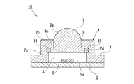
- FIG. 1 is a schematic cross-sectional view showing an example of an ultraviolet light emitting device in the present invention.
- the ultraviolet light emitting device 10 of this example includes a light emitting element 1, a lens (optical member) 9 made of polymer (I), and an adhesive portion 11 that bonds the light emitting element 1 and the lens 9.
- the light-emitting element 1 includes a substrate 3, an LED die 5 that generates ultraviolet rays having a wavelength of 200 to 400 nm, and a frame-shaped support base 7.
- the LED die 5 is mounted on the surface of the substrate 3.
- the support base 7 is disposed on the substrate 3 so as to surround the LED die 5.
- the lens 9 is disposed above the LED die 5 so as to be separated from the LED die 5 and close the opening of the support base 7.
- a space S for accommodating the LED die 5 is formed by the substrate 3, the support base 7, and the lens 9.
- Examples of the substrate 3 include a printed wiring board and a lead frame.
- the wavelength of ultraviolet rays generated by the LED die 5 is 200 to 400 nm, preferably 200 to 370 nm. The shorter the wavelength of ultraviolet light, the higher the utility of the present invention.
- Examples of the material of the LED die 5 include GaAs, AIN, AlGaN, and AlInGaN.
- the support base 7 has a side wall portion 7a and a top surface portion 7b. An opening 7c is formed in the top surface portion 7b. At the upper end of the inner wall of the side wall portion 7a, a groove 7d is formed over the entire circumference. An adhesive portion 11 is provided in the groove 7d.
- Materials for the support 7 include Kovar (Ni—Co alloy), Cu—Zn based copper alloy, Cu—Fe based copper alloy, Cr—Zr based copper alloy, alloys such as stainless steel, and metals such as Cu, Al, and Ni. , Ceramics such as alumina, and glass. Of these, alloys, ceramics, and Al are preferable in terms of light weight and excellent durability.
- the lens 9 includes a bullet-shaped lens body 9a having a dome shape on the top surface and a flat bottom surface, and a collar portion 9b provided on the entire peripheral surface of the lower end portion of the lens body 9a.
- the width of the flange portion 9b (the width in the direction perpendicular to the surface of the substrate 3) is substantially the same as the width of the groove 7d of the support base 7.
- the diameter of the lens body 9a is the same as or slightly smaller than the diameter of the opening 7c of the support base 7.
- the diameter of the flange 9b is larger than the diameter of the opening 7c of the support base 7 and the inner diameter of the side wall 7a. The size is smaller than that.
- the lens 9 when the lens 9 is inserted into the opening 7c from the lower side of the opening 7c of the support base 7, the upper surface of the flange portion 9b is in contact with the lower surface of the top surface portion 7b.
- the end of the flange portion 9 b is in contact with the adhesive portion 11, and is fixed to the support base 7 by the adhesive portion 11.
- the adhesion part 11 is formed from the adhesive agent of this invention.
- the ultraviolet light emitting device 10 is obtained by the following procedure. First, an adhesive is applied to the position of the groove 7d of the support base 7, and is dried as necessary. Next, the lens 9 is inserted into the opening 7c from the lower side of the opening 7c of the support base 7, and the flange 9b is brought into contact with the dried adhesive, and baked in that state. Thereby, the dried adhesive becomes the bonding part 11, and the support base 7 and the lens 9 are bonded by the bonding part 11. Next, the ultraviolet light emitting device 10 is obtained by arranging the support 7 to which the lens 9 is bonded on the substrate 3 on which the LED die 5 is mounted.
- a well-known coating method can be utilized.
- a spin coating method, a potting method, an ink jet method, a spray method, and the like can be given.
- a well-known drying method can be utilized. Examples thereof include heating, vacuum, and combined use of heating and vacuum.
- the baking temperature for bonding the support 7 and the lens 9 is typically a temperature equal to or higher than the T g of the polymer in the adhesive, and is higher than T g I and the T g of the polymer in the adhesive.
- T g above temperature of preferably the square, T g I and T g + 50 ° C. or higher temperatures higher of T g of the polymer in the adhesive is particularly preferred.
- the upper limit of the baking temperature is not particularly limited, in that the lens 9 are hardly degraded, T g + 100 ° C. or less preferably higher of the T g I and T g of the polymer in the adhesive, T g I and adhesion Of the T g of the polymer in the agent, the higher T g + 80 ° C. or less is particularly preferable.
- FIG. 2 is a schematic cross-sectional view illustrating another example of the ultraviolet light emitting device according to the present invention.
- the ultraviolet light emitting device 20 of this example includes a light emitting element 21, an optical fiber (optical member) 29, and an adhesive portion 31 that bonds the light emitting element 21 and the optical fiber 29.
- the light-emitting element 21 includes a substrate 23, an LED die 25 that generates ultraviolet rays having a wavelength of 200 to 400 nm, and a sealing material 27 made of polymer (I).
- substrate 23 has the wiring 23a for mounting the LED die
- the LED die 25 is mounted on the bottom surface of the recess 23b, and the sealing material 27 is filled in the recess 23b.
- the upper surface of the light emitting element 21 is a flat surface by the sealing material 27.
- An optical fiber 29 is fixed to the portion of the sealing material 27 on the upper surface of the light emitting element 21 by an adhesive portion 31.
- Examples of the material of the substrate 23 include kovar, Al, and ceramic.
- Examples of the material of the wiring 23a include Au, Ag, Al, and Cu.
- Examples of the material of the optical fiber 29 include quartz, sapphire, perfluoro fluororesin (for example, a polymer in CTX-809S (trade name, manufactured by Asahi Glass Co., Ltd.) used in the examples).
- An optical fiber 29 is disposed on the sealing material 27 of the light emitting element 21, the adhesive of the present invention is applied around the lower end of the optical fiber 29, dried as necessary, and then baked to seal it.
- the stop material 27 and the optical fiber 29 are bonded to obtain the ultraviolet light emitting device 20.
- the method of applying the adhesive and the method of drying are the same as described above, and the preferred range of baking is also the same as described above.
- FIG. 3 is a schematic cross-sectional view showing another example of the ultraviolet light emitting device in the present invention.
- the ultraviolet light emitting device 40 of this example includes a light emitting element 41, a light transmitting window (optical member) 49 on a flat plate made of polymer (I), a bonding portion 51 for bonding the light emitting element 41 and the light transmitting window 49, Is provided.
- the light emitting element 41 includes a substrate 43, a frame 45, and a plurality of LED dies 47 that generate ultraviolet rays having a wavelength of 200 to 400 nm.
- the LED die 47 is mounted on the surface of the substrate 43.
- the frame 45 is disposed on the substrate 43 so as to surround the plurality of LED dies 47.
- An adhesive portion 51 is formed on the upper surface of the frame 45.
- the translucent window 49 is disposed on the frame 45 so as to close the opening of the frame 45, and is bonded to the frame 45 by the bonding portion 51.
- the height of the frame 45 is higher than the height of the LED die 47, and the LED die 47 and the light transmission window 49 are separated from each other.
- a space S for accommodating a plurality of LED dies 47 is formed by the substrate 43, the frame 45, and the transparent window 49.
- Examples of the material of the substrate 43 and the frame 45 include Al, silicon, ceramics, SiC, GaN, glass, tungsten, molybdenum, and sapphire.
- the material of the substrate 43 and the frame 45 may be the same or different.
- LED die 47 the thing similar to the said LED die 5 is mentioned.
- the adhesive of the present invention is applied to the upper surface of the frame 45 of the light emitting element 41 and dried as necessary.
- a transparent window 49 is disposed on the frame 45 and baked in a state where it is in contact with the dried adhesive.
- the dried adhesive becomes the bonding part 51, and the frame 45 and the light transmission window 49 are bonded by the bonding part 51, and the ultraviolet light emitting device 40 is obtained.
- the method of applying the adhesive and the drying method are the same as described above, and the preferable baking range is also the same as described above.
- the ultraviolet light-emitting device in this invention is not limited to said example.
- Each configuration in the above example, a combination thereof, and the like are examples, and the addition, omission, replacement, and other changes of the configuration can be made without departing from the spirit of the present invention.
- the ultraviolet light emitting device is not limited to that shown in FIGS.
- the shape of the lens, the optical fiber, and the light transmission window, which are optical members, is not limited to those described above.
- As the light emitting element an LED element having a configuration other than the light emitting elements 1, 21, 41 may be used.
- the polymer (I) is preferably a fluoropolymer having a fluorine-containing aliphatic ring structure.
- the polymer (I) is preferably a perfluoropolymer except for the reactive functional group portion.
- the fluorinated alicyclic structure include those similar to the fluorinated alicyclic structure in the unit (a) of the polymer (II).
- the polymer (I) include a polymer having the unit (a).
- the unit (a) is preferably a unit having a fluorinated aliphatic ring structure in the main chain, particularly a unit formed by cyclopolymerization of a diene-based fluorinated monomer, and a unit based on a cyclic fluorinated monomer. preferable.
- the diene fluorine-containing monomer and the cyclic fluorine-containing monomer are the same as those described in the description of the unit (a), and preferred embodiments are also the same.
- the polymer (I) may have, for example, the aforementioned unit (b) and unit (c) in addition to the unit (a).
- the proportion of the unit (a) is 50 mol% based on the total of all the units constituting the polymer (I). The above is preferable, 75 mol% or more is more preferable, and 100 mol% is particularly preferable.
- the proportion of the unit (a) is preferably at least 20 mol%, preferably 40 mol%, based on the total of all units constituting the polymer (I). The above is more preferable, and 100 mol% is particularly preferable.
- the polymer (I) may or may not have a reactive functional group.
- the reactive functional group include those described above.
- the reactive functional group may be bonded to the main chain terminal of the polymer (I) or may be contained in a side group.
- the polymer (I) preferably has no reactive functional group. Therefore, it is preferable that the group bonded to the end of the main chain does not have the above-described units (b) and (c) and is a group other than a reactive functional group (for example, a trifluoromethyl group).
- the T g of the polymer (I) is preferably 90 ° C. or more, and particularly preferably 100 to 180 ° C.
- the combination of the adhesive portion and the optical element of the ultraviolet light-emitting device in this embodiment, i.e. in a combination of the polymer (I) and polymer (II) is higher than the T g of the polymer T g polymer of (I) (II) Such a combination is preferable.
- a light-emitting element including a member made of polymer (I) and an optical member made of polymer (I) may be used as long as the desired one is commercially available, or may be manufactured using polymer (I). Good.
- the polymer (I) may be used as long as the desired product is commercially available, and may be produced from various raw material compounds by an appropriate method such as polymerization.
- the polymer (I) can be produced according to the production method described in Japanese Patent No. 2526641.
- Examples of commercially available polymers (I) include Cytop (registered trademark, manufactured by Asahi Glass Co., Ltd.).
- Examples 1 to 10 described later examples 3, 5 to 6 and 8 to 10 are examples, Examples 1 to 2 and 4 are comparative examples, and Example 7 is a reference example.
- the materials and evaluation methods used in each example are shown below.
- Optical member (1) The following fluoropolymer (1) is press-molded into a film having a thickness of 200 ⁇ m.
- Fluoropolymer (1) A homopolymer obtained by cyclopolymerization of perfluoro (3-butenyl vinyl ether) (hereinafter also referred to as “BVE”), wherein the main chain end group is CF 3 .
- BVE perfluoro (3-butenyl vinyl ether)
- the fluoropolymer (1) was obtained by removing the solvent of CTX-809S (trade name, manufactured by Asahi Glass Co., Ltd.).
- Optical member (2) The following fluoropolymer (2) is press-molded into a film having a thickness of 200 ⁇ m.
- Fluoropolymer (2) A homopolymer obtained by cyclopolymerization of perfluoroallyl vinyl ether (hereinafter also referred to as “AVE”), wherein the main chain terminal group is COOH.
- AVE perfluoroallyl vinyl ether
- Fluoropolymer (2) is obtained by subjecting AVE to cyclopolymerization according to Example 1 of Japanese Patent No. 2526641 and then subjecting the polymer obtained according to Production Example 1 of International Publication No. 2010/032759 to heat treatment. After that, the terminal group was hydrolyzed to COOH.
- Optical member (3) The following fluoropolymer (3) is press-molded into a film having a thickness of 200 ⁇ m.
- Optical members (1) to (3) had a high transmittance of 80% or more at a wavelength of 200 to 400 nm.
- the transmittance was measured with a spectrophotometer UV-3100 (model number, manufactured by Shimadzu Corporation).
- a low-pressure mercury lamp made by USHIO INC., Model number: SUV-40L
- SUV-40L made of a fluorescent tube that cuts off a wavelength of 185 nm is adjusted so as to have an illuminance of 10 mW / cm 2. Irradiated for hours. After irradiation, the adhesion was evaluated by the same grid method as the initial adhesion.
- Heat-resistant The evaluation sample was set up vertically and placed in an 80 ° C. oven for 200 hours for heating. Then, the presence or absence of the detachment
- a fluoropolymer (5) was produced by the following procedure. 24.5 g of BVE, 3 g of CF 2 ⁇ CF—OCF 2 CF 2 CF 2 COOCH 3 (hereinafter also referred to as “MXM”), and Parroyl IPP (trade name, manufactured by NOF Corporation) as a polymerization initiator 0.04 g was put into an ampule and reacted at 40 ° C. for 24 hours to obtain a fluoropolymer (5).
- MXM CF 2 ⁇ CF—OCF 2 CF 2 CF 2 COOCH 3
- the obtained fluoropolymer (5) was dissolved in perfluorotributylamine to a concentration of 4% by mass to obtain an adhesive (c).
- a fluoropolymer (6) was obtained by reacting in the same manner as in Example 1 except that the amount of BVE was 7.9 g and the amount of MXM was 13 g.
- the obtained fluoropolymer (6) was dissolved in perfluorotributylamine to a concentration of 4% by mass to obtain an adhesive (d).
- Carbon black (manufactured by Mitsubishi Chemical Corporation, product number: MA-600) was dispersed in the solution produced in Production Example 2 so that the carbon black was 7% by mass with respect to the fluoropolymer to obtain an adhesive (e). .
- the fluoropolymer (7) was a polymer having a main chain terminal of COOCH 3 (confirmed by IR spectrum analysis), and T g was 108 ° C.
- the obtained fluoropolymer (7) was dissolved in perfluorotributylamine so as to have a concentration of 4% by mass.
- carbon black manufactured by Mitsubishi Chemical Corporation, product number: MA-600 was dispersed so that the carbon black was 7% by mass with respect to the fluoropolymer to obtain an adhesive (i).
- Example 1 An evaluation sample was prepared using the adhesive obtained in each production example, and initial adhesion, light resistance, and heat resistance were evaluated. The results are shown in Table 1. Further, also shown a T g of the fluoropolymer constituting the type and optical members of optical members used in the production of the evaluation samples in each Example in Table 1. In addition, about Example 1 whose evaluation result of initial adhesion was x, light resistance and heat resistance were not evaluated.
- Examples 3, 5 to 6 and 8 to 10 using the adhesive of the present invention were all excellent in initial adhesion, light resistance and heat resistance.
- Example 1 using a silane coupling agent generally used for improving adhesion initial adhesion was poor.
- T g is Example 2 using 100 ° C. greater than the fluoropolymer, light resistance was poor.
- Example 4 using a polymer with a Tg of 10 ° C was inferior in heat resistance. From the results of Examples 2-4, by changing the ratio of BVE and MXM, it was confirmed that can vary widely with T g.
- Adhesives example 7 is used a homopolymer of AVE in (f), it is impossible to select the T g.
- T g is an advantageous effect in terms of such range of selection of the adhesive members spreads.
Landscapes
- Chemical & Material Sciences (AREA)
- Organic Chemistry (AREA)
- Health & Medical Sciences (AREA)
- Chemical Kinetics & Catalysis (AREA)
- Medicinal Chemistry (AREA)
- Polymers & Plastics (AREA)
- Inorganic Chemistry (AREA)
- General Chemical & Material Sciences (AREA)
- Adhesives Or Adhesive Processes (AREA)
- Led Device Packages (AREA)
Abstract
Description
たとえば前記特許文献2では、特定のA群から選択されたホモポリマーまたはB、C、D群からのコポリマーであるフルオロポリマーを接着剤組成物の成分として用いることが提案されている。
特許文献3では、ぺルフルオロアリルビニルエーテルの環化重合により得られるポリマーやぺルフルオロブテニルビニルエーテルの環化重合により得られるポリマーを含む接着剤が、石英製のレンズの貼り合わせに使用されている。
特許文献3に記載の接着剤においては、本発明者によれば、光学素子や光学部材の種類によっては、密着性が不充分になることがある。
本発明は、波長200~400nmの紫外線を光源とし、含フッ素脂肪族環構造を有するポリマーからなる部材が優れた密着性で接着され、前記紫外線や熱に曝されても前記部材の密着性が低下しにくい紫外線発光装置を提供することを他の目的とする。
[1]下記紫外線発光装置の接着部を形成するための接着剤であって、含フッ素脂肪族環構造を有するフルオロポリマーを含む下記接着剤(A)または下記接着剤(B)のいずれかからなることを特徴とする接着剤。
紫外線発光装置:波長200~400nmの紫外線を発生させる発光素子と、前記発光素子から発生する紫外線が透過する光学部材と、前記発光素子と前記光学部材とを接着する、接着剤から形成される接着部と、を備える。
接着剤(A):前記フルオロポリマーのガラス転移温度が30~100℃であり、かつ、紫外線遮断剤を含まない接着剤。
接着剤(B):前記フルオロポリマーと紫外線遮断剤とを含む接着剤。
[3]前記接着剤(B)における紫外線遮断剤の含有量が、前記フルオロポリマーに対して0.1~20質量%である、[1]または[2]の接着剤。
[4]前記接着剤(B)における紫外線遮断剤が無機粒子および有機粒子からなる群から選択される少なくとも1種である、[1]~[3]のいずれかの接着剤。
[5]前記フルオロポリマーが、側鎖または主鎖末端に反応性官能基を有し、該反応性官能基を有する部分を除いて炭素原子に結合した水素原子を有しないフルオロポリマーである、[1]~[4]のいずれかの接着剤。
[7]前記光学材料中のフルオロポリマーのガラス転移温度が、前記接着剤中のフルオロポリマーのガラス転移温度以上である、[6]の接着剤。
[8]前記光学材料中のフルオロポリマーのガラス転移温度が100~180℃である、[6]または[7]の接着剤。
[10]前記単位(a)における含フッ素脂肪族環の環を構成する炭素原子の少なくとも1つが、ポリマーの主鎖を構成する炭素原子である、[9]の接着剤。
[11]前記単位(a)が、炭素原子に結合した水素原子を有しない単位である、[9]または[10]の接着剤。
[12]前記単位(a)が、ジエン系含フッ素単量体の環化重合により形成された単位である、[9]~[11]のいずれかの接着剤。

記発光素子と前記光学部材とは、[1]~[13]の接着剤から形成される接着部で接着されることを特徴とする紫外線発光装置。
本発明の紫外線発光装置は、含フッ素脂肪族環構造を有するフルオロポリマー等からなる部材が優れた密着性で接着され、波長200~400nmの紫外線や熱に曝されても前記部材の密着性が低下しにくい。
ポリマーの「単位」は、単量体が重合することによって形成された、該単量体に由来する、ポリマーの構成部分を示す。単位は、重合反応によって直接形成された単位であってもよく、重合反応によって得られた重合体を化学変換することによって該単位の一部の構造が別の構造に変換された単位であってもよい。
「含フッ素脂肪族環構造」とは、環の主骨格を構成する炭素原子の少なくとも一部に、フッ素原子またはフッ素含有基が結合している脂肪族環構造を意味する。フッ素含有基としては、ペルフルオロアルキル基、ペルフルオロアルコキシ基、=CF2等が挙げられる。該環の主骨格を構成する炭素原子の一部に、含フッ素基以外の置換基が結合していてもよい。
「脂肪族環構造」とは、芳香族性を有さない飽和または不飽和の環構造を意味する。
「エーテル性酸素原子」とは、炭素-炭素原子間に1個存在する酸素原子(-C-O-C-)である。
「ペルフルオロアルキル基」とは、アルキル基の水素原子のすべてがフッ素原子に置換された基である。「ペルフルオロアルキレン基」とは、アルキレン基の水素原子のすべてがフッ素原子に置換された基である。
「ペルフルオロポリマー」とは、炭素原子に結合した水素原子を有しない含フッ素ポリマーをいう。
「ガラス転移温度」(以下、「Tg」ともいう。)とは、JIS K 7121:2012年版に準拠して測定される中間点ガラス転移温度(Tmg)を意味する。
本明細書においては、式(1)で表される化合物を「化合物(1)」とも記し、式(1)で表される単位を「単位(1)」とも記す。他の式で表される化合物、単位等についても同様に記す。
本発明の接着剤は、下記紫外線発光装置の接着部を形成するための接着剤であって、含フッ素脂肪族環構造を有するフルオロポリマーを含む下記接着剤(A)または下記接着剤(B)のいずれかからなることを特徴とする接着剤。
紫外線発光装置:波長200~400nmの紫外線を発生させる発光素子と、前記発光素子から発生する紫外線が透過する光学部材と、前記発光素子と前記光学部材とを接着する、接着剤から形成される接着部と、を備える。
接着剤(A):前記フルオロポリマーのガラス転移温度が30~100℃であり、かつ、紫外線遮断剤を含まない接着剤。
接着剤(B):前記フルオロポリマーと紫外線遮断剤とを含む接着剤。
接着部が接する発光素子の表面および光学部材の表面は種々の部品からなる。該表面を形成する材料としては、光学特性に優れかつ接着部との親和性に優れる点から、含フッ素脂肪族環構造を有するフルオロポリマーが好ましい。
接着剤(A)は、含フッ素脂肪族環構造を有するフルオロポリマーであって、ガラス転移温度が30~100℃であるポリマー(以下、「ポリマー(II)」ともいう。)を有する。接着剤(A)は、必要に応じて、ポリマー(II)および紫外線遮断剤以外の成分をさらに含んでもよい。接着剤(A)は、必要に応じて、溶媒をさらに含んでもよい。
接着剤(A)は、接着剤(A)中のポリマー(II)のTg以上の温度でベークすると、接着剤(A)中のポリマー(II)が低粘性化し、発光素子または発光部材の表面の凹凸に浸透し、アンカー効果が得られる。
ポリマー(II)としては、下記単位(a)と下記単位(b)とを有するポリマーが好ましい。必要に応じて、単位(a)および単位(b)以外の単位(以下、「単位(c)」ともいう。)をさらに有してもよい。ポリマー(II)が単位(a)を有することで、後述するポリマー(I)からなる光学部材の表面との親和性に優れる。ポリマー(II)が単位(b)を有することで、ポリマー(II)中の反応性官能基が発光素子または発光部材を形成する材料と化学反応する。そのため、発光素子と光学部材との間に初期の優れた密着性が得られる。
ポリマー(II)は、接着性を高める反応性官能基の存在を除いて、ペルフルオロポリマーであることが好ましい。したがって、ポリマー(II)を構成する単位は、反応性官能基を有する単量体に基づく単位を除いて、ペルフルオロ単量体(すなわち、炭素原子に結合した水素原子を有しない含フッ素単量体)に基づく単位(以下、「ペルフルオロ単位」ともいう。)であることが好ましい。反応性官能基を有する含フッ素単量体に基づく単位についても、その反応性官能基の部分(たとえば、単位(b)におけるX)を除いて、炭素原子に結合した水素原子を有しないことが好ましい。
反応性官能基については後で詳述する。
単位(a)は、含フッ素脂肪族環構造を有する単位である。
単位(a)はペルフルオロ単位であることが好ましい。
含フッ素脂肪族環構造における含フッ素脂肪族環は、環骨格が炭素原子のみから構成される炭素環構造のものであってもよく、環骨格に炭素原子以外の原子(ヘテロ原子)を含む複素環構造のものであってもよい。該ヘテロ原子としては酸素原子、窒素原子等が挙げられる。
含フッ素脂肪族環の環骨格を構成する原子の数は、4~7個が好ましく、5または6個が特に好ましい。すなわち、脂肪族環は4~7員環であることが好ましく、5または6員環が特に好ましい。
含フッ素脂肪族環構造が「主鎖を構成する」とは、含フッ素脂肪族環構造の環骨格を構成する炭素原子のうち、少なくとも1つが、ポリマーの主鎖を構成する炭素原子であることを意味する。重合性二重結合に由来する2個の炭素原子がポリマーの主鎖を構成することより、言い換えれば、含フッ素脂肪族環構造の環を構成する炭素原子の1個または隣接する2個が1つの重合性二重結合に由来する炭素原子であることを意味する。
たとえば、単位(a)が、モノエン系単量体が付加重合することによって形成されたものである場合、重合性二重結合に由来する2個の炭素原子が主鎖を構成し、その2個の炭素原子が環骨格の隣接する2個の炭素原子であるか、または、その2個の炭素原子のうちの1個が環骨格の炭素原子である。また、単位(a)が、ジエン系単量体が環化重合することによって形成されたものである場合、2つの重合性二重結合に由来する合計4個の炭素原子が主鎖を構成し、その4個の炭素原子のうちの2~4個が環骨格を構成する炭素原子である。
重合性二重結合としては、特に限定されないが、ビニル基、アリル基、アクリロイル基、メタクリロイル基が好ましい。これらの重合性二重結合においては、炭素原子に結合した水素原子の一部または全部がフッ素原子で置換されていてもよい。
ジエン系含フッ素単量体としては、下記化合物(ma1)が好ましい。
CF2=CF-Q-CF=CF2 ・・・(ma1)。
(ただし、Qは、フッ素原子の一部がフッ素原子以外のハロゲン原子で置換されていてもよく、エーテル性酸素原子を有していてもよい炭素数1~6のペルフルオロアルキレン基である。)
該ペルフルオロアルキレン基は、フッ素原子の一部がフッ素原子以外のハロゲン原子で置換されていてもよい。フッ素原子以外のハロゲン原子としては、塩素原子、臭素原子等が挙げられる。
該ペルフルオロアルキレン基は、エーテル性酸素原子を有していてもよい。
Qとしては、エーテル性酸素原子を有するペルフルオロアルキレン基が好ましい。その場合、該ペルフルオロアルキレン基におけるエーテル性酸素原子は、該ペルフルオロアルキレン基の一方の末端に存在していてもよく、該ペルフルオロアルキレン基の両末端に存在していてもよく、該ペルフルオロアルキレン基の炭素原子間に存在していてもよい。環化重合性の点から、該ペルフルオロアルキレン基の一方の末端に存在していることが好ましい。
-(CR1R2)h- ・・・(q-1)
-(CR3R4)iO(CR5R6)j- ・・・(q-2)
(ただし、R1、R2、R3、R4、R5およびR6は、それぞれ独立に、フッ素原子、塩素原子、トリフルオロメチル基またはトリフルオロメトキシ基である。hは2~4の整数であって複数のR1およびR2はそれぞれ異なっていてもよく、iおよびjはそれぞれ0~3の整数であって、i+jは1~3の整数であり、iが2または3の場合複数のR3およびR4はそれぞれ異なっていてもよく、jが2または3の場合複数のR5およびR6はそれぞれ異なっていてもよい。)
hは2または3であることが好ましくR1およびR2はすべてフッ素原子であるか1つまたは2つを除いてすべてフッ素原子であることが好ましい。iは0であってかつjは1または2であることが好ましく、R5およびR6はすべてフッ素原子であるか1つまたは2つを除いてすべてフッ素原子であることが好ましい。
CF2=CFOCF2CF=CF2、
CF2=CFOCF(CF3)CF=CF2、
CF2=CFOCF2CF2CF=CF2、
CF2=CFOCF2CF(CF3)CF=CF2、
CF2=CFOCF(CF3)CF2CF=CF2、
CF2=CFOCFClCF2CF=CF2、
CF2=CFOCCl2CF2CF=CF2、
CF2=CFOCF2OCF=CF2、
CF2=CFOC(CF3)2OCF=CF2、
CF2=CFOCF2CF(OCF3)CF=CF2、
CF2=CFCF2CF=CF2、
CF2=CFCF2CF2CF=CF2、
CF2=CFCF2OCF2CF=CF2。
環状含フッ素単量体としては、下記の化合物(ma2)または化合物(ma3)が好ましい。

X1、X2、X3、X4、Y1およびY2におけるペルフルオロアルコキシ基としては、前記ペルフルオロアルキル基に酸素原子(-O-)が結合したものが挙げられ、トリフルオロメトキシ基が特に好ましい。
前記ペルフルオロアルキル基またはペルフルオロアルコキシ基の炭素数が2以上である場合、該ペルフルオロアルキル基またはペルフルオロアルコキシ基の炭素原子間にエーテル性酸素原子(-O-)が介在してもよい。
X2はフッ素原子、トリフルオロメチル基または炭素数1~4のペルフルオロアルコキシ基であることが好ましく、フッ素原子またはトリフルオロメトキシ基が特に好ましい。
X3およびX4はそれぞれ独立に、フッ素原子または炭素数1~4のペルフルオロアルキル基であることが好ましく、フッ素原子またはトリフルオロメチル基が特に好ましい。
X3およびX4は相互に結合して環を形成してもよい。前記環の環骨格を構成する原子の数は、4~7個が好ましく、5~6個であることがより好ましい。
化合物(ma3)の好ましい具体例として、化合物(ma31)~(ma32)が挙げられる。

下記単位(a1)~(a4)は化合物(ma1)の環化重合により形成された単位であり、化合物(ma1)の環化重合により下記単位(a1)~(a4)の少なくとも1種が生成する。その際、下記単位(a1)~(a4)のうち、脂肪族環の環骨格を構成する原子の数が5または6個となる構造の単位が生成しやすい。それらの単位の2種以上が含まれるポリマーが生成することもある。言い換えれば、化合物(ma1)としては、下記単位(a1)~(a4)における、Q中の原子を含めた環骨格を構成する原子の数が5または6個となる構造の化合物(ma1)が好ましい。
下記単位(a5)は化合物(ma2)から形成された単位であり、下記単位(a6)は化合物(ma3)から形成された単位である。
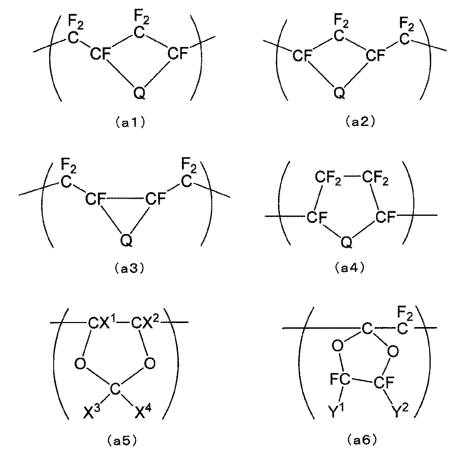
ポリマー(II)が有する単位(a)は1種でも2種以上でもよい。
単位(b)は、下式(b)で表される単位である。
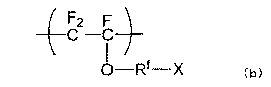
該ペルフルオロアルキレン基はエーテル性酸素原子を有していてもよい。この場合、ペルフルオロアルキレン基中のエーテル性酸素原子の数は、1個でもよく2個以上でもよい。
Rfの具体例としては、下記のものが挙げられる。
-CF2CF2CF2-、
-CF2CF(CF3)OCF2CF2-、
-CF2CF2CF(CF3)OCF2CF2-、
-CF2CF(CF3)OCF2CF2CF2-。
Xとしては、COOCH3、SO2F、COOH、SO3Hが好ましい。
-OCF2CF(CF3)OCF2CF2COOCH3、
-OCF2CF2CF2COOCH3、
-OCF2CF(CF3)OCF2CF2SO2F、
-OCF2CF2CF2COOH、
-OCF2CF(CF3)OCF2CF2CF2COOCH3、
-OCF2CF(CF3)OCF2CF2SO3H。
単位(b)は、CF2=CF-O-Rf-Xを重合させることにより形成できる。
単位(c)は、単位(a)および単位(b)以外の他の単位である。
単位(c)としては、単位(a)単位(b)それぞれを形成する単量体と共重合可能な単量体に基づくものであればよく、特に限定されない。たとえば、重合性二重結合と反応性官能基とを有する単量体に基づく単位(ただし、単位(b)を除く。)(以下、「単位(c1)」ともいう。)、テトラフルオロエチレン等の含フッ素オレフィンに基づく単位、含フッ素ビニルエーテルに基づく単位等が挙げられる。
重合性二重結合としては、CF2=CF-、CF2=CH-、CH2=CF-、CFH=CF-、CFH=CH-、CF2=C<、-CF=CF-等が挙げられる。
単位(c)としては、単位(c1)を除いて、ペルフルオロ単位であることが好ましい。単位(c1)の場合は、その反応性官能基の部分を除いて、炭素原子に結合した水素原子を有しないことが好ましい。
ポリマー(II)中の単位(a)と単位(b)との合計の含有量は、ポリマー(II)を構成する全単位の合計に対して50~100モル%であり、75~100モル%が好ましく、85~100モル%が特に好ましい。単位(a)と単位(b)との合計の含有量が前記範囲の下限値以上であれば、ポリマー(II)がポリマー(I)からなる部材の表面との親和性、および接着剤から形成される接着部とポリマー(I)からなる部材との密着性に優れる。
反応性官能基は、ベーク等を行った際に、反応性官能基を有するポリマーの分子間、または該ポリマー以外の他の物質(金属、合金等)と反応して化学結合(水素結合、共有結合等)を形成し得る反応性を有する基を意味する。
反応性官能基としては、たとえば、カルボキシ基、酸ハライド基、アルコキシカルボニル基、カルボニルオキシ基、カーボネート基、スルホ基、ホスホノ基、ヒドロキシ基、チオール基、シラノール基等が挙げられる。
ポリマー(II)は、単位(b)に由来するもの以外の他の反応性官能基を有してもよく、有しなくてもよい。他の反応性官能基は、ポリマー(II)の主鎖末端に結合していてもよく、側基に含まれてもよい。たとえば前出の単位(c1)を有する場合、他の反応性官能基を側基に含むものとなる。
ポリマー(II)のTg(以下、「Tg II」ともいう。)は、30~100℃であり、40~95℃が好ましく、60~90℃が特に好ましい。
Tg IIが前記範囲の上限値以下であれば、接着部が優れたタック性を有する。また、ポリマー(I)や他の材料からなる部材を接着する際のベーク(たとえば100℃以上のベーク)で接着剤の粘性が下がり、部材の表面の凹凸に接着剤が浸透し、接着部と部材との間の接着にアンカー効果が得られる。これらタック性やアンカー効果により、前記の部材と接着部とが優れた密着性を有する。該密着性は物理的作用(タック性、アンカー効果)によるものであるため、波長200~400nmの紫外線に曝された場合でも密着性が低下しにくい。
Tg IIが前記範囲の下限値以上であれば、LED等の紫外線発光装置を構成する部材に求められる耐熱性や耐ヒートサイクル性を充分に有する。たとえば80℃以上の高温条件下や-40~80℃のヒートサイクル条件下でも、接着部が溶融しにくく、接着している部材が剥離しにくい。
ポリマー(II)の質量平均分子量は、1万~15万が好ましく、3万~13万がより好ましく、3万~12万が特に好ましい。ポリマー(II)の質量平均分子量が前記範囲の下限値以上であれば、接着部の機械的強度に優れ、上限値以下であれば、溶媒への溶解性に優れる。
ポリマー(II)の平均分子量は、ゲル透過クロマトグラフィにより測定される。
接着剤(A)中の固形分に対するポリマー(II)の割合の上限は特に限定されず、100質量%であってもよい。任意に配合される紫外線遮断剤以外の成分等の含有量に応じて適宜設定できる。
なお、接着剤(A)の固形分濃度は、接着剤の塗布方法、形成しようとする塗膜の厚さ等に応じて適宜設定すればよく、1~30質量%が好ましく、1~20質量%が特に好ましい。
ポリマー(II)および紫外線遮断剤以外の成分としては、本発明の効果を損なわないものであれば特に限定されない。たとえば、屈折率を上げるためのSiO2。ZrO2、TiO2等のゾル、接着性を向上するためのアミノシランやエポキシシラン等が挙げられる。これらはいずれか1種を単独で用いてもよく2種以上を併用してもよい。
なお、ポリマー(I)~(III)、溶媒および紫外線遮断剤以外の成分を、以下、「他の成分」ともいう。
材料(A)中の他の成分の含有量は、本発明の効果を損なわない範囲で、他の成分の種類に応じて適宜設定できる。
材料(A)における溶媒としては、少なくともポリマー(II)を溶解する溶媒が用いられる。材料(A)が紫外線遮断剤として無機粒子および有機粒子からなる群から選択される少なくとも1種を含む場合、ポリマー(II)を溶解する溶媒は、紫外線遮断剤を分散する分散媒としての機能を有してもよい。
溶媒としては、プロトン性溶媒、非プロトン性溶媒等が挙げられる。「プロトン性溶媒」とは、プロトン供与性を有する溶媒である。「非プロトン性溶媒」とは、プロトン供与性を有さない溶媒である。
メタノール、エタノール、1-プロパノール、イソプロピルアルコール、1-ブタノール、2-ブタオール、t-ブタノール、ペンタノール、ヘキサノール、1-オクタノール、2-オクタノール、エチレングリコール、エチレングリコールモノメチルエーテル、プロピレングリコールモノメチルエーテル、プロピレングリコールモノブチルエーテル、プロピレングリコール、乳酸メチル等のプロトン性非含フッ素溶媒。
2-(ペルフルオロオクチル)エタノール等の含フッ素アルコール、含フッ素カルボン酸、含フッ素カルボン酸のアミド、含フッ素スルホン酸等のプロトン性含フッ素溶媒。
ヘキサン、シクロヘキサン、ヘプタン、オクタン、デカン、ドデカン、デカリン、アセトン、シクロヘキサノン、2-ブタノン、ジメトキシエタン、モノメチルエーテル、酢酸エチル、酢酸ブチル、ジグライム、トリグライム、プロピレングリコールモノメチルエーテルモノアセテート(PGMEA)、N,N-ジメチルホルムアミド(DMF)、N,N-ジメチルアセトアミド(DMA)、N-メチルピロリドン、テトラヒドロフラン、アニソール、ジクロロメタン、ジクロロエタン、クロロホルム、四塩化炭素、クロロベンゼン、ジクロロベンゼン、ベンゼン、トルエン、キシレン、エチルベンゼン、メシチレン、テトラリン、メチルナフタレン等の非プロトン性非含フッ素溶媒。
1,4-ビス(トリフルオロメチル)ベンゼン等のポリフルオロ芳香族化合物、ペルフルオロトリブチルアミン等のポリフルオロトリアルキルアミン化合物、ペルフルオロデカリン等のポリフルオロシクロアルカン化合物、ペルフルオロ(2-ブチルテトラヒドロフラン)等のポリフルオロ環状エーテル化合物、ペルフルオロポリエーテル、ポリフルオロアルカン化合物、ハイドロフルオロエーテル(HFE)等の非プロトン性含フッ素溶媒。
これらのうち、ポリマー(II)の溶解に用いる溶媒としては、ポリマー(II)の溶解度が大きく、良溶媒である点で、非プロトン性含フッ素溶媒が好ましい。
溶媒として、ポリマー(I)からなる部材等の、接着しようとする部材を溶解する溶媒を用いることも好ましい。これにより、該部材と接着部との間の密着性がより優れる。
溶媒の沸点は、接着剤(1)を塗布した際に均一な塗膜を形成しやすいことから、65~220℃が好ましく、70~220℃が特に好ましい。
溶媒の含有量は、接着剤(A)の固形分濃度に応じて設定される。
接着剤材料(A)は、ポリマー(II)またはその溶液を得て、必要に応じて他の成分、溶媒等を混合することにより調製できる。
ポリマー(II)またはその溶液は、所望のものが市販されていればそれを用いてもよく、各種原料化合物から重合等の適当な方法により製造してもよい。たとえば、特許第2526641号公報等に記載された製造方法に準じてポリマー(II)を製造できる。
接着剤(B)は、含フッ素脂肪族環構造を有するフルオロポリマー(以下、接着剤(B)中に含まれる該フルオロポリマーを「ポリマー(III)」ともいう。)と紫外線遮断剤とを含む接着剤である。接着剤(B)が紫外線遮断剤を含むと、波長200~400nmの紫外線によるポリマー(III)の劣化や分解、それに伴う密着性の低下がより生じにくい。接着剤(B)がポリマー(III)と紫外線遮断剤を含むことで、接着部が波長200~400nmの紫外線を光源とする紫外線発光装置に用いられるポリマー(I)からなる部材を、他の材料からなる部材やポリマー(I)からなる他の部材に対し、優れた密着性で接着できる。また、該密着性が、波長200~400nmの紫外線や高温(たとえば50~90℃)に曝されても低下しにくく、耐光性や耐熱性にも優れる。
接着剤(B)は、必要に応じて、溶媒をさらに含んでいてもよい。
ポリマー(III)は、含フッ素脂肪族環構造を有する。
ポリマー(III)は、反応性官能基が存在する場合はその反応性官能基部分を除いて、ペルフルオロポリマーであることが好ましい。
含フッ素脂肪族環構造としては、ポリマー(II)の単位(a)における含フッ素脂肪族環構造と同様のものが挙げられる。
ポリマー(III)としては、たとえば、前記単位(a)を有するフルオロポリマーが挙げられる。単位(a)としては、主鎖に含フッ素脂肪族環構造を有する単位が好ましく、ジエン系含フッ素単量体の環化重合により形成された単位、環状含フッ素単量体に基づく単位が特に好ましい。
ジエン系含フッ素単量体、環状含フッ素単量体はそれぞれ、単位(a)の説明で挙げたものと同様であり、好ましい態様も同様である。
ポリマー(III)は、単位(a)以外に、たとえば前述の単位(b)、単位(c)を有していてもよい。
単位(a)として環状含フッ素単量体に基づく単位を有する場合、単位(a)の割合は、ポリマー(III)を構成する全単位の合計に対し、20モル%以上が好ましく、40モル%以上がより好ましく、100モル%が特に好ましい。
なお、ジエン系含フッ素単量体と環状含フッ素単量体との共重合により得られる重合体は、環状含フッ素単量体に基づく単位を有するポリマーとして考える。
接着剤(B)が、ポリマー(I)からなる部材とポリマー(I)以外の他の材料からなる部材とを接着する場合や、ポリマー(I)が反応性官能基を有する場合、ポリマー(III)が反応性官能基を有すると、他の材料やポリマー(I)の反応性官能基と反応し、より優れた密着性が得られる。また、接着剤(B)が紫外線遮断剤を含むため、反応性官能基の紫外線による分解が生じにくく、反応性官能基による効果が長期にわたって発揮されやすい。
反応性官能基としては、前記と同様のものが挙げられる。
反応性官能基としては、カルボキシ基、酸ハライド基、アルコキシカルボニル基、カルボニルオキシ基、カーボネート基、スルホ基、ホスホノ基、ヒドロキシ基、チオール基、シラノール基およびアルコキシシリル基からなる群から選ばれる少なくとも1種が好ましく、カルボキシ基またはアルコキシカルボニル基が特に好ましい。
反応性官能基は、ポリマー(III)の主鎖末端に結合していてもよく、側基に含まれてもよい。側基に含まれる場合には、前述のポリマー(II)中の単位(b)を含むポリマーであることが好ましい。その際、ポリマー(III)中の単位(a)と単位(b)との合計の含有量の好ましい範囲としては、ポリマー(II)と同様のものが挙げられる。製造しやすい点からは、主鎖末端に結合していることが好ましい。主鎖末端に反応性官能基が含まれる場合には、重合開始剤または連鎖移動剤として反応性官能基を有する化合物を使用して得られるポリマーであることが好ましい。
紫外線遮断剤は、紫外線を吸収する機能および紫外線を反射する機能のいずれか一方または両方を有する添加剤である。
紫外線遮断剤としては、特に限定されず、公知のものを使用できる。接着剤の貯蔵安定性に優れる点では、無機粒子および有機粒子からなる群から選択される少なくとも1種が好ましい。
無機粒子および有機粒子からなる群から選択される少なくとも1種である場合の紫外線遮断剤の平均粒子径は、0.01~5μmが好ましく、0.01~3μmが特に好ましい。
有機粒子としては、樹脂粒子等が挙げられる。具体例としては、ポリテトラフルオロエチレン(PTFE)粒子、ポリフェニレンスルフィド粒子、ポリアミドイミド粒子、ポリエーテルスルホン粒子、エポキシ粒子、ナイロン粒子、ポリメタクリル酸エステル粒子等が挙げられる。
これらの粒子はいずれか1種を単独で用いてもよく2種以上を併用してもよい。
上記の中では、カーボンブラック、PTFE粒子、TiO2粒子、SiO2粒子、ZnO粒子、ZrO2粒子が好ましい。
接着剤(B)中の固形分に対するポリマー(III)と紫外線遮断剤との合計の割合の上限は特に限定されず、100質量%であってもよい。任意に配合される他の成分の含有量に応じて適宜設定できる。
なお、接着剤(B)の固形分は、ポリマー(III)と紫外線遮断剤と他の成分との合計量である。
他の成分としては、第一の態様における他の成分と同様のものが挙げられる。
接着剤(B)中の他の成分の含有量は、本発明の効果を損なわない範囲で、他の成分の種類に応じて適宜設定できる。
接着剤(B)における溶媒としては、少なくともポリマー(III)を溶解する溶媒が用いられる。ポリマー(III)を溶解する溶媒は、紫外線遮断剤を分散する分散媒としての機能を有してもよい。
溶媒としては、第一の態様における溶媒と同様のものが挙げられ、好ましい態様も同様である。
材料(B)の固形分濃度は、接着剤の塗布方法、形成しようとする塗膜の厚さ等に応じて適宜設定すればよく、1~30質量%が好ましく、1~20質量%が特に好ましい。
接着剤(B)は、ポリマー(III)またはその溶液と、紫外線遮断剤と、必要に応じて他の成分、溶媒等を混合することにより調製できる。
ポリマー(III)またはその溶液は、所望のものが市販されていればそれを用いてもよく、各種原料化合物から重合等の適当な方法により製造してもよい。たとえば、特許第2526641号公報等に記載された製造方法に準じてポリマー(III)を製造できる。
図1は、本発明における紫外線発光装置の一例を示す概略断面図である。
この例の紫外線発光装置10は、発光素子1と、ポリマー(I)からなるレンズ(光学部材)9と、発光素子1とレンズ9とを接着する接着部11と、を備える。
発光素子1は、基板3と、波長200~400nmの紫外線を発生するLEDダイ5と、枠状の支持台7と、を備える。
LEDダイ5は基板3の表面に実装されている。
支持台7は、基板3上に、LEDダイ5を囲むように配置されている。
レンズ9は、LEDダイ5の上方にLEDダイ5から離間して、支持台7の開口を塞ぐように配置されている。
紫外線発光装置10においては、基板3と支持台7とレンズ9とによって、LEDダイ5を収容する空間Sが形成されている。
LEDダイ5が発生する紫外線の波長は200~400nmであり、200~370nmが好ましい。紫外線の波長が短いほど、本発明の有用性が高い。
LEDダイ5の材質としては、GaAs、AIN、AlGaN、AlInGaN等が挙げられる。
支持台7の材料としては、コバール(Ni-Co合金)、Cu-Zn系銅合金、Cu-Fe系銅合金、Cr-Zr系銅合金、ステンレス等の合金、Cu、Al、Ni等の金属、アルミナ等のセラミックス、ガラス等が挙げられる。これらのうち、軽量かつ耐久性に優れる点で、合金、セラミックス、Alが好ましい。
鍔部9bの幅(基板3の表面に対して垂直方向における幅)は、支持台7の溝7dの幅とほぼ同じである。
レンズ本体9aの直径は、支持台7の開口7cの直径と同じかわずかに小さい大きさであり、鍔部9bの直径は、支持台7の開口7cの直径より大きく、かつ側壁部7aの内径よりも小さい大きさとされている。これにより、支持台7の開口7cの下側からレンズ9を開口7cに挿入したときに、鍔部9bの上面が天面部7bの下面と接するようになっている。
レンズ9は、鍔部9bの先端が接着部11と接しており、接着部11により支持台7に固定されている。
たとえば、以下の手順で紫外線発光装置10が得られる。まず、支持台7の溝7dの位置に接着剤を塗布し、必要に応じて乾燥する。次いで、支持台7の開口7cの下側からレンズ9を開口7cに挿入して鍔部9bを、乾燥させた接着剤と接触させ、その状態でベークする。これにより、乾燥させた接着剤が接着部11となり、接着部11によって支持台7とレンズ9とが接着される。次いで、レンズ9が接着された支持台7を、LEDダイ5が実装された基板3上に配置することで、紫外線発光装置10が得られる。
塗布後の乾燥方法としては、特に限定されず、公知の乾燥方法を利用できる。加熱、真空、加熱と真空の併用等が挙げられる。
ベーク温度の上限は、特に限定されないが、レンズ9が劣化しにくい点で、Tg Iおよび接着剤中のポリマーのTgのうち高い方のTg+100℃以下が好ましく、Tg Iおよび接着剤中のポリマーのTgのうち高い方のTg+80℃以下が特に好ましい。
この例の紫外線発光装置20は、発光素子21と、光ファイバ(光学部材)29と、発光素子21と光ファイバ29とを接着する接着部31と、を備える。
発光素子21は、基板23と、波長200~400nmの紫外線を発生するLEDダイ25と、ポリマー(I)からなる封止材27とを備える。
基板23は、LEDダイ25を実装するための配線23aと、凹部23bとを有し、配線23aは、凹部23bの底面に設けられている。凹部23bの底面にLEDダイ25が実装され、凹部23b内に封止材27が充填されている。発光素子21の上面は、封止材27によって平坦面となっている。発光素子21の上面の封止材27の部分に、接着部31によって光ファイバ29が固定されている。
配線23aの材質としては、Au、Ag、Al、Cu等が挙げられる。
LEDダイ25としては、前記のLEDダイ5と同様のものが挙げられる。
光ファイバ29の材質としては、石英、サファイア、ペルフルオロフッ素樹脂(たとえば実施例で使用のCTX-809S(商品名、旭硝子社製)中のポリマー)等が挙げられる。
接着剤の塗布方法よび乾燥方法は前記と同様であり、ベークの好ましい範囲も前記と同様である。
この例の紫外線発光装置40は、発光素子41と、ポリマー(I)からなる平板上の透光窓(光学部材)49と、発光素子41と透光窓49とを接着する接着部51と、を備える。
発光素子41は、基板43と、フレーム45と、波長200~400nmの紫外線を発生する複数のLEDダイ47とを備える。
LEDダイ47は基板43の表面に実装されている。フレーム45は、基板43上に、複数のLEDダイ47を囲むように配置されている。フレーム45の上面に接着部51が形成されている。透光窓49は、フレーム45の上にフレーム45の開口を塞ぐように配置され、接着部51によってフレーム45と接着されている。フレーム45の高さはLEDダイ47の高さよりも高く、LEDダイ47と透光窓49は離間している。
紫外線発光装置40においては、基板43とフレーム45と透光窓49とによって、複数のLEDダイ47を収容する空間Sが形成されている。
LEDダイ47としては、前記のLEDダイ5と同様のものが挙げられる。
接着剤の塗布方法および乾燥方法は前記と同様であり、ベークの好ましい範囲も前記と同様である。
紫外線発光装置は、図1~3に示すものに限定されない。
光学部材であるレンズ、光ファイバ、透光窓の形状は前記のものに限定されない。
発光素子は、発光素子1、21、41以外の構成のLED素子を用いてもよい。
ポリマー(I)は、含フッ素脂肪族環構造を有するフルオロポリマーが好ましい。
ポリマー(I)は、反応性官能基が存在する場合はその反応性官能基部分を除いて、ペルフルオロポリマーであることが好ましい。
含フッ素脂肪族環構造としては、ポリマー(II)の単位(a)における含フッ素脂肪族環構造と同様のものが挙げられる。
ポリマー(I)としては、たとえば、前記単位(a)を有するポリマーが挙げられる。単位(a)としては、主鎖に含フッ素脂肪族環構造を有する単位が好ましく、ジエン系含フッ素単量体の環化重合により形成された単位、環状含フッ素単量体に基づく単位が特に好ましい。
ジエン系含フッ素単量体、環状含フッ素単量体はそれぞれ、単位(a)の説明で挙げたものと同様であり、好ましい態様も同様である。
ポリマー(I)は、単位(a)以外に、たとえば前述の単位(b)、単位(c)を有していてもよい。
単位(a)として環状含フッ素単量体に基づく単位を有する場合、単位(a)の割合は、ポリマー(I)を構成する全単位の合計に対し、20モル%以上が好ましく、40モル%以上がより好ましく、100モル%が特に好ましい。
反応性官能基を有する場合、反応性官能基は、ポリマー(I)の主鎖末端に結合していてもよく、側基に含まれてもよい。
波長200~400nmの紫外線に対する透明性、耐光性の点では、ポリマー(I)は反応性官能基を有しないことが好ましい。したがって、前述の単位(b)、単位(c)を有さず、主鎖末端に結合する基が反応性官能基以外の基(たとえばトリフルオロメチル基)であることが好ましい。
後述の例1~10のうち、例3、5~6および8~10が実施例であり、例1~2および4が比較例であり、例7が参考例である。
各例で使用した材料および評価方法を以下に示す。
光学部材(1):下記フルオロポリマー(1)を、厚さ200μmのフィルム状になるようプレス成形したもの。
フルオロポリマー(1):ペルフルオロ(3-ブテニルビニルエーテル)(以下、「BVE」ともいう。)を環化重合して得られたホモポリマーであって、主鎖末端基がCF3であるポリマー。
フルオロポリマー(1)は、CTX-809S(商品名、旭硝子社製)の溶媒を除去することにより得た。
フルオロポリマー(2):ペルフルオロアリルビニルエーテル(以下、「AVE」ともいう。)を環化重合して得られたホモポリマーであって、主鎖末端基がCOOHであるポリマー。
フルオロポリマー(2)は、特許第2526641号公報の実施例1に準じてAVEを環化重合した後、国際公開第2010/032759号の製造例1に準じて得られた重合体に熱処理を行った後、末端基を加水分解してCOOHとした。
フルオロポリマー(3):2,2-ビストリフルオロメチル-4,5-ジフルオロ-1,3-ジオキソールとテトラフルオロエチレンとの共重合体であるテフロン(登録商標)AF1600。テフロン(登録商標)AF1600を溶媒に溶解してなるテフロン(登録商標)AF1600S(三井・デュポンフロロケミカル社製)の溶媒を除去することより得た。
ガラス転移温度(Tg):
JIS K 7121:2012年版に準拠して測定した中間点ガラス転移温度である。
スピンコータに3cm角の基板(材質:コバール)を設置し、毎分1,000回の回転数で回転させ、基板表面に接着剤を0.5mL滴下し、150℃で1時間ベークして乾燥膜を形成した。次いで、2cm角に切った光学部材を乾燥膜の上に載せ、150℃で2時間ベークした。これにより、基板/接着部/光学部材の層構成の評価サンプルを得た。
評価サンプル(基板/接着部/光学部材)の光学部材に、Cotec社製クロスカットガイドCCI-2(型番)を用いてカッターで2mm×2mmサイズのセルを25マス切った。その後、該光学部材上にセロテープ(登録商標)(ニチバン社製、型番:CT-18)を貼り、剥離する操作を10回行った。評価サンプルの光学部材面を20倍光学顕微鏡で観察し、25マスのうち剥離しなかったマスの数を数えた。
上記の結果から、剥離しなかったマスの数が20個以上であった場合を○(良好)、剥離しなかったマスの数が20個未満であった場合を×(不良)とした。
波長185nmをカットする蛍光管からなる低圧水銀灯(ウシオ電機社製、型番:SUV-40L)を、照度10mW/cm2になるよう調整し、評価サンプルの光学部材面に紫外線(波長254nm)を200時間照射した。照射後、初期密着と同じ碁盤目法で密着性を評価した。
評価サンプルを垂直に立て、80℃オーブンに200時間入れて加熱した。その後、光学部材の脱離や位置のずれの有無を目視で確認した。
光学部材の脱離が起きず、初期(加熱前)と同じ位置であった場合を○(良好)、光学部材の脱離が起きた場合と、脱離が起きなくても初期の位置から1mm以上ずれた場合を×(不良)とした。
3-アミノプロピルトリメトキシシランを濃度0.1質量%になるようにエタノールで希釈して接着剤(a)を得た。
CTL-809A(商品名、旭硝子社製)にペルフルオロトリブチルアミンを追加して、フルオロポリマー(4)が濃度4質量%の溶液を調整し、接着剤(b)とした。フルオロポリマー(4)は、前記フルオロポリマー(2)と同様のBVEを環化重合して得られたホモポリマーであって、主鎖末端基がCOOHであるポリマーであり、Tgは108℃であった。
特許第2526641号公報の実施例11を参照し、以下の手順でフルオロポリマー(5)を製造した。
BVEの24.5gと、CF2=CF-OCF2CF2CF2COOCH3(以下、「MXM」ともいう。)の3gと、重合開始剤としてパーロイルIPP(商品名、日本油脂社製)の0.04gとをアンプルに入れ、40℃で24時間反応させてフルオロポリマー(5)を得た。フルオロポリマー(5)の組成は、BVEの環化重合により形成された単位/MXMに基づく単位=9/1(モル比)であり、Tgは73℃であった。
得られたフルオロポリマー(5)をペルフルオロトリブチルアミンに、濃度4質量%となるように溶解して接着剤(c)を得た。
BVEの量を7.9gとし、MXMの量を13gとした以外は例1と同様に反応を行ってフルオロポリマー(6)を得た。フルオロポリマー(6)の組成は、BVEの環化重合により形成された単位/MXMに基づく単位=4/6(モル比)であり、Tgは10℃であった。
得られたフルオロポリマー(6)をペルフルオロトリブチルアミンに、濃度4質量%となるように溶解して接着剤(d)を得た。
製造例2で製造した溶液にカーボンブラック(三菱化学社製、品番:MA-600)を、カーボンブラックがフルオロポリマーに対して7質量%となるように分散させて接着剤(e)を得た。
前記フルオロポリマー(2)をペルフルオロトリブチルアミンに、濃度4質量%となるように溶解して接着剤(f)を得た。
製造例2で製造した溶液にPTFE微粒子(旭硝子社製、品番:L170A)を、PTFE微粒子がフルオロポリマーに対して7質量%となるように分散させて接着剤(g)を得た。
製造例2で製造した溶液にTiO2微粒子(堺化学工業社製、品番:D-2667)を、TiO2微粒子がフルオロポリマーに対して7質量%となるように分散させて接着剤(h)を得た。
BVEの100gと、連鎖移動剤としてメタノールの0.5gと、重合開始剤としてパーロイルIPP(商品名、日本油脂社製)の0.7gとをオートクレーブ(耐圧ガラス製)を入れて密閉した。オートクレーブ内で40℃で22時間反応させて、BVEの環化重合体を得た。該重合体の固有粘度は、30℃のペルフルオロ(2-ブチルテトラヒドロフラン)中で0.2dl/gであった。次に該重合体を熱風循環式オーブン中で、大気雰囲気下にて300℃で1時間熱処理し、さらにメタノール中に60℃で20時間浸漬した。次いで100℃で24時間真空乾燥させてフルオロポリマー(7)を得た。フルオロポリマー(7)は、主鎖末端がCOOCH3であるポリマーであり(IRスペクトル分析で確認。)、Tgは108℃であった。
得られたフルオロポリマー(7)をペルフルオロトリブチルアミンに、濃度4質量%となるように溶解した。さらに、カーボンブラック(三菱化学社製、品番:MA-600)を、カーボンブラックがフルオロポリマーに対して7質量%となるように分散させて、接着剤(i)を得た。
各製造例で得た接着剤を用いて評価サンプルを作製し、初期密着、耐光性、耐熱性を評価した。結果を表1に示す。また、各例で評価サンプルの作製に用いた光学部材の種類と該光学部材を構成するフルオロポリマーのTgを表1に併記する。
なお、初期密着の評価結果が×であった例1については、耐光性および耐熱性の評価は行わなかった。
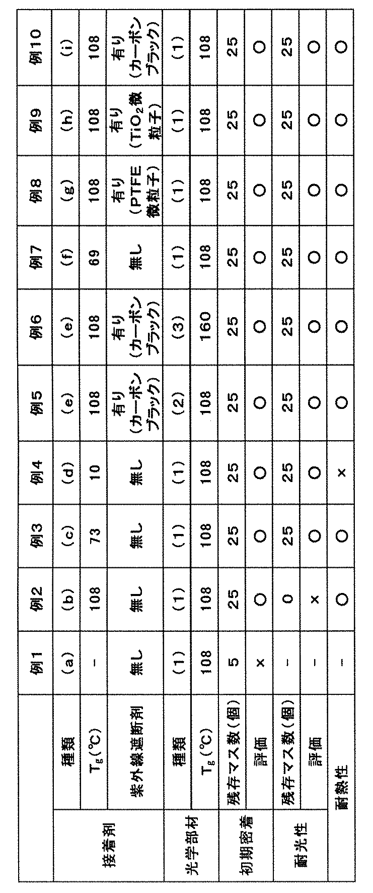
密着性向上のために一般的に用いられているシランカップリング剤を用いた例1は初期密着が悪かった。
Tgが100℃超のフルオロポリマーを用いた例2は、耐光性が悪かった。
Tg10℃のポリマーを用いた例4は、耐熱性が劣っていた。
また、例2~4の結果から、BVEとMXMとの比率を変化させることで、Tgを幅広く変化させ得ることが確認できた。AVEのホモポリマーを用いている例7の接着剤(f)では、Tgを選択することができない。幅広いTgを選択できることは、接着する部材の選択の幅が広がる等の点で有利な効果である。
なお、2014年7月15日に出願された日本特許出願2014-144975号の明細書、特許請求の範囲、要約書および図面の全内容をここに引用し、本発明の明細書の開示として、取り入れるものである。
Claims (14)
- 下記紫外線発光装置の接着部を形成するための接着剤であって、含フッ素脂肪族環構造を有するフルオロポリマーを含む下記接着剤(A)または下記接着剤(B)のいずれかからなることを特徴とする接着剤。
紫外線発光装置:波長200~400nmの紫外線を発生させる発光素子と、前記発光素子から発生する紫外線が透過する光学部材と、前記発光素子と前記光学部材とを接着する、接着剤から形成される接着部と、を備える。
接着剤(A):前記フルオロポリマーのガラス転移温度が30~100℃であり、かつ、紫外線遮断剤を含まない接着剤。
接着剤(B):前記フルオロポリマーと紫外線遮断剤とを含む接着剤。 - 前記接着剤(B)における前記フルオロポリマーのガラス転移温度が30~100℃である、請求項1に記載の接着剤。
- 前記接着剤(B)における紫外線遮断剤の含有量が、前記フルオロポリマーに対して0.1~20質量%である、請求項1または2に記載の接着剤。
- 前記接着剤(B)における紫外線遮断剤が無機粒子および有機粒子からなる群から選択される少なくとも1種である、請求項1~3のいずれか一項に記載の接着剤。
- 前記フルオロポリマーが、側鎖または主鎖末端に反応性官能基を有し、該反応性官能基を有する部分を除いて炭素原子に結合した水素原子を有しないフルオロポリマーである、請求項1~4のいずれか一項に記載の接着剤。
- 前記光学材料が含フッ素脂肪族環構造を有するフルオロポリマーから形成されている、請求項1~5のいずれか一項に記載の接着剤。
- 前記光学材料中のフルオロポリマーのガラス転移温度が、前記接着剤中のフルオロポリマーのガラス転移温度以上である、請求項6に記載の接着剤。
- 前記光学材料中のフルオロポリマーのガラス転移温度が100~180℃である、請求項6または7に記載の接着剤。
- 前記含フッ素脂肪族環構造を有するフルオロポリマーが、含フッ素脂肪族環構造を有する単位(a)を有するポリマーである、請求項1~8のいずれか一項に記載の接着剤。
- 前記単位(a)における含フッ素脂肪族環の環を構成する炭素原子の少なくとも1つが、ポリマーの主鎖を構成する炭素原子である、請求項9に記載の接着剤。
- 前記単位(a)が、炭素原子に結合した水素原子を有しない単位である、請求項9または10に記載の接着剤。
- 前記単位(a)が、ジエン系含フッ素単量体の環化重合により形成された単位である、請求項9~11のいずれか一項に記載の接着剤。
- 前記ガラス転移温度が30~100℃のフルオロポリマーが、前記単位(a)と下式(b)で表される単位(b)とを有し、前記単位(a)と前記単位(b)との合計の含有量が、全単位の合計に対し50~100モル%であるフルオロポリマーである、請求項9~12のいずれか一項に記載の接着剤。

- 波長200~400nmの紫外線を発生する発光素子、および、波長200~400nmの紫外線が透過する光学部材、を有する紫外線発光装置であって、
記発光素子と前記光学部材とは、請求項1~13のいずれか一項に記載の接着剤から形成される接着部で接着されることを特徴とする紫外線発光装置。
Priority Applications (5)
| Application Number | Priority Date | Filing Date | Title |
|---|---|---|---|
| CN201580038461.0A CN106488964B (zh) | 2014-07-15 | 2015-07-14 | 紫外线发光装置用粘接剂和紫外线发光装置 |
| KR1020177000713A KR102342911B1 (ko) | 2014-07-15 | 2015-07-14 | 자외선 발광 장치용 접착제 및 자외선 발광 장치 |
| EP15821675.4A EP3170875B1 (en) | 2014-07-15 | 2015-07-14 | Adhesive for ultraviolet-light-emitting device, and ultraviolet-light-emitting device |
| JP2016534451A JP6465113B2 (ja) | 2014-07-15 | 2015-07-14 | 紫外線発光装置用接着剤および紫外線発光装置 |
| US15/401,772 US10246615B2 (en) | 2014-07-15 | 2017-01-09 | Ultraviolet-light-emitting device with adhesive having low glass transition temperature |
Applications Claiming Priority (2)
| Application Number | Priority Date | Filing Date | Title |
|---|---|---|---|
| JP2014-144975 | 2014-07-15 | ||
| JP2014144975 | 2014-07-15 |
Related Child Applications (1)
| Application Number | Title | Priority Date | Filing Date |
|---|---|---|---|
| US15/401,772 Continuation US10246615B2 (en) | 2014-07-15 | 2017-01-09 | Ultraviolet-light-emitting device with adhesive having low glass transition temperature |
Publications (1)
| Publication Number | Publication Date |
|---|---|
| WO2016010043A1 true WO2016010043A1 (ja) | 2016-01-21 |
Family
ID=55078533
Family Applications (1)
| Application Number | Title | Priority Date | Filing Date |
|---|---|---|---|
| PCT/JP2015/070172 Ceased WO2016010043A1 (ja) | 2014-07-15 | 2015-07-14 | 紫外線発光装置用接着剤および紫外線発光装置 |
Country Status (7)
| Country | Link |
|---|---|
| US (1) | US10246615B2 (ja) |
| EP (1) | EP3170875B1 (ja) |
| JP (1) | JP6465113B2 (ja) |
| KR (1) | KR102342911B1 (ja) |
| CN (1) | CN106488964B (ja) |
| TW (1) | TWI663243B (ja) |
| WO (1) | WO2016010043A1 (ja) |
Cited By (7)
| Publication number | Priority date | Publication date | Assignee | Title |
|---|---|---|---|---|
| CN107275465A (zh) * | 2017-06-29 | 2017-10-20 | 华中科技大学鄂州工业技术研究院 | Led封装及其制作方法 |
| WO2019039440A1 (ja) * | 2017-08-23 | 2019-02-28 | 日本碍子株式会社 | 透明封止部材及び光学部品 |
| WO2021020565A1 (ja) * | 2019-07-31 | 2021-02-04 | 日東電工株式会社 | 発光素子封止用樹脂組成物、光源装置及び光源装置の製造方法 |
| JP2021118199A (ja) * | 2020-01-22 | 2021-08-10 | スタンレー電気株式会社 | 深紫外光を発する発光装置及びそれを用いた水殺菌装置 |
| JP7196208B2 (ja) | 2020-01-08 | 2022-12-26 | ダイキン工業株式会社 | 絶縁膜又は誘電膜 |
| CN116239944A (zh) * | 2023-01-18 | 2023-06-09 | 广州城建职业学院 | 一种吸收红外、防水的建筑材料及其制备方法和应用 |
| US12504149B2 (en) | 2023-12-26 | 2025-12-23 | Nichia Corporation | Light-emitting device |
Families Citing this family (5)
| Publication number | Priority date | Publication date | Assignee | Title |
|---|---|---|---|---|
| CN106848031A (zh) * | 2015-12-04 | 2017-06-13 | 财团法人工业技术研究院 | 紫外光发光二极管的封装结构 |
| CN111052421A (zh) * | 2017-08-30 | 2020-04-21 | 日本碍子株式会社 | 透明密封构件 |
| KR102642878B1 (ko) * | 2018-06-11 | 2024-03-05 | 서울바이오시스 주식회사 | 발광 다이오드 패키지 및 발광 다이오드 패키지를 포함하는 광 조사 장치 |
| CN111477732B (zh) | 2019-01-24 | 2021-10-08 | 隆达电子股份有限公司 | 发光装置 |
| CN112086547A (zh) | 2019-06-13 | 2020-12-15 | 光宝光电(常州)有限公司 | 发光二极管封装结构 |
Citations (5)
| Publication number | Priority date | Publication date | Assignee | Title |
|---|---|---|---|---|
| JPH0284456A (ja) * | 1988-09-20 | 1990-03-26 | Asahi Glass Co Ltd | 光学素子用接着剤 |
| JP2001330943A (ja) * | 2000-03-15 | 2001-11-30 | Asahi Glass Co Ltd | ペリクル |
| JP2004536171A (ja) * | 2001-05-14 | 2004-12-02 | イー・アイ・デュポン・ドウ・ヌムール・アンド・カンパニー | 紫外線及び真空紫外線の透明性を必要とする適用での部分フッ素化ポリマーの使用 |
| JP2006093372A (ja) * | 2004-09-24 | 2006-04-06 | Nichia Chem Ind Ltd | 半導体装置 |
| JP2013542096A (ja) * | 2010-09-10 | 2013-11-21 | サン−ゴバン パフォーマンス プラスティックス コーポレイション | Uv抵抗性の透明積層体 |
Family Cites Families (7)
| Publication number | Priority date | Publication date | Assignee | Title |
|---|---|---|---|---|
| JP2526641B2 (ja) | 1987-08-14 | 1996-08-21 | 旭硝子株式会社 | 新規含フッ素環状重合体 |
| JP2000103812A (ja) * | 1998-09-30 | 2000-04-11 | Asahi Glass Co Ltd | 銅含有フッ素樹脂の成形物 |
| JP2001226313A (ja) * | 2000-02-14 | 2001-08-21 | Asahi Glass Co Ltd | フッ素化ビニルエーテル化合物、その製造方法、および含フッ素重合体 |
| US6548129B2 (en) | 2000-03-15 | 2003-04-15 | Asahi Glass Company, Limited | Pellicle |
| AU2003257654A1 (en) | 2002-08-21 | 2004-03-11 | Asahi Glass Company, Limited | Ultraviolet-permeable fluoropolymers and pellicles made by using the same |
| CA2655180A1 (en) * | 2006-06-12 | 2007-12-21 | Asahi Glass Company, Limited | Curable composition and fluorinated cured product |
| KR101516358B1 (ko) * | 2012-03-06 | 2015-05-04 | 삼성전자주식회사 | 발광 장치 |
-
2015
- 2015-07-14 KR KR1020177000713A patent/KR102342911B1/ko active Active
- 2015-07-14 WO PCT/JP2015/070172 patent/WO2016010043A1/ja not_active Ceased
- 2015-07-14 JP JP2016534451A patent/JP6465113B2/ja active Active
- 2015-07-14 TW TW104122733A patent/TWI663243B/zh active
- 2015-07-14 EP EP15821675.4A patent/EP3170875B1/en active Active
- 2015-07-14 CN CN201580038461.0A patent/CN106488964B/zh active Active
-
2017
- 2017-01-09 US US15/401,772 patent/US10246615B2/en active Active
Patent Citations (5)
| Publication number | Priority date | Publication date | Assignee | Title |
|---|---|---|---|---|
| JPH0284456A (ja) * | 1988-09-20 | 1990-03-26 | Asahi Glass Co Ltd | 光学素子用接着剤 |
| JP2001330943A (ja) * | 2000-03-15 | 2001-11-30 | Asahi Glass Co Ltd | ペリクル |
| JP2004536171A (ja) * | 2001-05-14 | 2004-12-02 | イー・アイ・デュポン・ドウ・ヌムール・アンド・カンパニー | 紫外線及び真空紫外線の透明性を必要とする適用での部分フッ素化ポリマーの使用 |
| JP2006093372A (ja) * | 2004-09-24 | 2006-04-06 | Nichia Chem Ind Ltd | 半導体装置 |
| JP2013542096A (ja) * | 2010-09-10 | 2013-11-21 | サン−ゴバン パフォーマンス プラスティックス コーポレイション | Uv抵抗性の透明積層体 |
Non-Patent Citations (1)
| Title |
|---|
| See also references of EP3170875A4 * |
Cited By (15)
| Publication number | Priority date | Publication date | Assignee | Title |
|---|---|---|---|---|
| CN107275465A (zh) * | 2017-06-29 | 2017-10-20 | 华中科技大学鄂州工业技术研究院 | Led封装及其制作方法 |
| US11195980B2 (en) | 2017-08-23 | 2021-12-07 | Ngk Insulators, Ltd. | Transparent sealing member and optical component |
| WO2019039440A1 (ja) * | 2017-08-23 | 2019-02-28 | 日本碍子株式会社 | 透明封止部材及び光学部品 |
| JPWO2019039440A1 (ja) * | 2017-08-23 | 2020-08-20 | 日本碍子株式会社 | 透明封止部材及び光学部品 |
| WO2021020565A1 (ja) * | 2019-07-31 | 2021-02-04 | 日東電工株式会社 | 発光素子封止用樹脂組成物、光源装置及び光源装置の製造方法 |
| JP2021024901A (ja) * | 2019-07-31 | 2021-02-22 | 日東電工株式会社 | 発光素子封止用樹脂組成物、光源装置及び光源装置の製造方法 |
| JP7225054B2 (ja) | 2019-07-31 | 2023-02-20 | 日東電工株式会社 | 発光素子封止用樹脂組成物、光源装置及び光源装置の製造方法 |
| JP2023059896A (ja) * | 2019-07-31 | 2023-04-27 | 日東電工株式会社 | 発光素子封止用樹脂組成物、光源装置及び光源装置の製造方法 |
| JP7432776B2 (ja) | 2019-07-31 | 2024-02-16 | 日東電工株式会社 | 発光素子封止用樹脂組成物、光源装置及び光源装置の製造方法 |
| JP7196208B2 (ja) | 2020-01-08 | 2022-12-26 | ダイキン工業株式会社 | 絶縁膜又は誘電膜 |
| JP2021118199A (ja) * | 2020-01-22 | 2021-08-10 | スタンレー電気株式会社 | 深紫外光を発する発光装置及びそれを用いた水殺菌装置 |
| JP7397687B2 (ja) | 2020-01-22 | 2023-12-13 | スタンレー電気株式会社 | 深紫外光を発する発光装置及びそれを用いた水殺菌装置 |
| CN116239944A (zh) * | 2023-01-18 | 2023-06-09 | 广州城建职业学院 | 一种吸收红外、防水的建筑材料及其制备方法和应用 |
| CN116239944B (zh) * | 2023-01-18 | 2024-04-05 | 广州城建职业学院 | 一种吸收红外、防水的建筑材料及其制备方法和应用 |
| US12504149B2 (en) | 2023-12-26 | 2025-12-23 | Nichia Corporation | Light-emitting device |
Also Published As
| Publication number | Publication date |
|---|---|
| EP3170875B1 (en) | 2020-11-04 |
| JPWO2016010043A1 (ja) | 2017-05-25 |
| CN106488964A (zh) | 2017-03-08 |
| US10246615B2 (en) | 2019-04-02 |
| KR20170033292A (ko) | 2017-03-24 |
| CN106488964B (zh) | 2018-09-21 |
| JP6465113B2 (ja) | 2019-02-06 |
| KR102342911B1 (ko) | 2021-12-23 |
| TWI663243B (zh) | 2019-06-21 |
| TW201610086A (zh) | 2016-03-16 |
| US20170114253A1 (en) | 2017-04-27 |
| EP3170875A4 (en) | 2018-01-24 |
| EP3170875A1 (en) | 2017-05-24 |
Similar Documents
| Publication | Publication Date | Title |
|---|---|---|
| JP6465113B2 (ja) | 紫外線発光装置用接着剤および紫外線発光装置 | |
| JP5783902B2 (ja) | 太陽電池の光電地要素のための白色顔料を含む不透明フルオロポリマー組成物 | |
| CN101925622A (zh) | 固化性组合物、含氟固化物、使用其的光学材料及发光元件 | |
| JP6432524B2 (ja) | 含フッ素架橋体の製造方法およびその使用 | |
| CN101466744A (zh) | 固化性组合物及含氟固化物 | |
| WO2010074038A1 (ja) | 発光素子モジュールおよびその製造方法 | |
| JP6642580B2 (ja) | 含フッ素重合体、その製造方法、および含フッ素重合体の硬化物 | |
| CN109641992B (zh) | 含氟聚合物、其制造方法、以及具备含氟聚合物的固化物的物品 | |
| TW201139472A (en) | Fluoropolymer and curable fluorinated resin composition | |
| JP6927283B2 (ja) | 含フッ素重合体、その硬化物の製造方法および発光装置 | |
| JP7432776B2 (ja) | 発光素子封止用樹脂組成物、光源装置及び光源装置の製造方法 | |
| CN104520098A (zh) | 玻璃片氟树脂层叠体 | |
| US20220332880A1 (en) | Encapsulation resin | |
| JP6830168B1 (ja) | 電子部品の製造方法 | |
| JP6368940B2 (ja) | 含フッ素芳香族化合物、その製造方法、硬化性材料、その硬化物、及び光学部材 | |
| JP2008162191A (ja) | 光学素子の製造方法 | |
| WO2021153336A1 (ja) | フッ素樹脂シート及びその製造方法 |
Legal Events
| Date | Code | Title | Description |
|---|---|---|---|
| 121 | Ep: the epo has been informed by wipo that ep was designated in this application |
Ref document number: 15821675 Country of ref document: EP Kind code of ref document: A1 |
|
| ENP | Entry into the national phase |
Ref document number: 2016534451 Country of ref document: JP Kind code of ref document: A |
|
| ENP | Entry into the national phase |
Ref document number: 20177000713 Country of ref document: KR Kind code of ref document: A |
|
| NENP | Non-entry into the national phase |
Ref country code: DE |
|
| REEP | Request for entry into the european phase |
Ref document number: 2015821675 Country of ref document: EP |
|
| WWE | Wipo information: entry into national phase |
Ref document number: 2015821675 Country of ref document: EP |