WO2016013103A1 - 検査方法 - Google Patents
検査方法 Download PDFInfo
- Publication number
- WO2016013103A1 WO2016013103A1 PCT/JP2014/069660 JP2014069660W WO2016013103A1 WO 2016013103 A1 WO2016013103 A1 WO 2016013103A1 JP 2014069660 W JP2014069660 W JP 2014069660W WO 2016013103 A1 WO2016013103 A1 WO 2016013103A1
- Authority
- WO
- WIPO (PCT)
- Prior art keywords
- nozzle
- suction nozzle
- pallet
- determined
- inspection method
- Prior art date
- Legal status (The legal status is an assumption and is not a legal conclusion. Google has not performed a legal analysis and makes no representation as to the accuracy of the status listed.)
- Ceased
Links
Images


Classifications
-
- G—PHYSICS
- G06—COMPUTING OR CALCULATING; COUNTING
- G06T—IMAGE DATA PROCESSING OR GENERATION, IN GENERAL
- G06T7/00—Image analysis
- G06T7/0002—Inspection of images, e.g. flaw detection
- G06T7/0004—Industrial image inspection
-
- H—ELECTRICITY
- H05—ELECTRIC TECHNIQUES NOT OTHERWISE PROVIDED FOR
- H05K—PRINTED CIRCUITS; CASINGS OR CONSTRUCTIONAL DETAILS OF ELECTRIC APPARATUS; MANUFACTURE OF ASSEMBLAGES OF ELECTRICAL COMPONENTS
- H05K13/00—Apparatus or processes specially adapted for manufacturing or adjusting assemblages of electric components
- H05K13/04—Mounting of components, e.g. of leadless components
- H05K13/0404—Pick-and-place heads or apparatus, e.g. with jaws
- H05K13/0408—Incorporating a pick-up tool
- H05K13/0409—Sucking devices
-
- G—PHYSICS
- G01—MEASURING; TESTING
- G01D—MEASURING NOT SPECIALLY ADAPTED FOR A SPECIFIC VARIABLE; ARRANGEMENTS FOR MEASURING TWO OR MORE VARIABLES NOT COVERED IN A SINGLE OTHER SUBCLASS; TARIFF METERING APPARATUS; MEASURING OR TESTING NOT OTHERWISE PROVIDED FOR
- G01D5/00—Mechanical means for transferring the output of a sensing member; Means for converting the output of a sensing member to another variable where the form or nature of the sensing member does not constrain the means for converting; Transducers not specially adapted for a specific variable
- G01D5/26—Mechanical means for transferring the output of a sensing member; Means for converting the output of a sensing member to another variable where the form or nature of the sensing member does not constrain the means for converting; Transducers not specially adapted for a specific variable characterised by optical transfer means, i.e. using infrared, visible, or ultraviolet light
- G01D5/28—Mechanical means for transferring the output of a sensing member; Means for converting the output of a sensing member to another variable where the form or nature of the sensing member does not constrain the means for converting; Transducers not specially adapted for a specific variable characterised by optical transfer means, i.e. using infrared, visible, or ultraviolet light with deflection of beams of light, e.g. for direct optical indication
- G01D5/30—Mechanical means for transferring the output of a sensing member; Means for converting the output of a sensing member to another variable where the form or nature of the sensing member does not constrain the means for converting; Transducers not specially adapted for a specific variable characterised by optical transfer means, i.e. using infrared, visible, or ultraviolet light with deflection of beams of light, e.g. for direct optical indication the beams of light being detected by photocells
Definitions
- the present invention relates to an inspection method for inspecting whether or not a suction nozzle is stored in a nozzle storage portion.
- suction nozzles corresponding to the shape, size, etc. of the electronic components are used, and thus many suction nozzles are required. For this reason, a nozzle pallet or the like that can store the suction nozzle is used, and the suction nozzle is managed in a state of being stored in the nozzle pallet. At this time, it is necessary to detect the storage location of the suction nozzle in the nozzle pallet or the like. For this reason, it is inspected whether the suction nozzle is housed in a nozzle housing section such as a nozzle pallet.
- the following patent document describes a method for inspecting whether or not the suction nozzle is housed in the nozzle housing section using reflected light.
- the inspection method described in the above patent document it is possible to determine whether or not the suction nozzle is housed in the nozzle housing portion to some extent.
- the reflected light may not be reflected in an appropriate direction by the foreign matter.
- the suction nozzle is not stored in the nozzle storage unit, it may be erroneously determined that the suction nozzle is stored in the nozzle storage unit.
- This invention is made
- an inspection method for inspecting whether or not the suction nozzle is housed in the nozzle housing portion
- the inspection method includes: A determination step for determining whether or not the nozzle is stored in the nozzle storage portion, and when it is determined by the determination step that the suction nozzle is stored in the nozzle storage portion, air is ejected toward the storage portion. And a re-determination step of determining whether or not the suction nozzle is housed in the nozzle housing portion after the air is ejected by the air ejection step.
- each of the determination step and the re-determination step images the nozzle storage portion, and imaging data obtained by imaging. Based on the above, it is a step of determining whether or not the suction nozzle is housed in the nozzle housing portion.
- the nozzle storage portion penetrates in the vertical direction and is blocked by the suction nozzle when the suction nozzle is stored.
- a reflection member is provided below the through hole, and each of the determination step and the re-determination step includes the reflected light from the reflection member in the imaging data obtained by imaging.
- the step of determining that the suction nozzle is stored in the nozzle storage portion and determining that the suction nozzle is not stored in the nozzle storage portion when the reflected light from the reflection member is included It is characterized by being.
- each of the determination step and the re-determination step is written on the suction nozzle in imaging data obtained by imaging.
- the identification symbol is included, it is determined that the suction nozzle is stored in the nozzle storage portion, and when the identification symbol is not included, it is determined that the suction nozzle is not stored in the nozzle storage portion. It is characterized by being.
- the nozzle storage unit is imaged, and whether or not the suction nozzle is stored in the nozzle storage unit is determined based on imaging data obtained by imaging. Thereby, it is possible to suitably determine whether or not the suction nozzle is stored in the nozzle storage portion.
- the nozzle housing portion penetrates in the vertical direction, and a reflecting member is provided below the nozzle housing portion. Then, when the imaging data obtained by the imaging of the nozzle storage unit does not include the reflected light from the reflecting member, it is determined that the suction nozzle is stored in the nozzle storage unit. On the other hand, when the imaging data includes light reflected by the reflecting member, it is determined that the suction nozzle is not stored in the nozzle storage unit. When such a determination is made, if a foreign object adheres to the reflecting member, the reflected light is not regularly reflected by the foreign object, and erroneous determination is likely to occur. For this reason, in the inspection method described in this section, the effect of blowing off the foreign matters by the ejection of air is fully utilized.
- the suction nozzle is stored in the nozzle storage portion. It is determined that On the other hand, when the identification data is not included in the imaging data, it is determined that the suction nozzle is not stored in the nozzle storage unit. When such a determination is made, if a foreign substance is attached to the identification symbol, the identification symbol cannot be read properly and erroneous determination is likely to occur. For this reason, in the inspection method described in this section, the effect of blowing off the foreign matters by the ejection of air is fully utilized.
- FIG. 1 shows an electronic component mounting apparatus (hereinafter sometimes abbreviated as “mounting apparatus”) 10.
- the mounting apparatus 10 includes one system base 12 and two electronic component mounting machines (hereinafter, may be abbreviated as “mounting machines”) 14 adjacent on the system base 12.
- the direction in which the mounting machines 14 are arranged is referred to as the X-axis direction, and the horizontal direction perpendicular to the direction is referred to as the Y-axis direction.
- Each mounting machine 14 mainly includes a mounting machine main body 20, a transport device 22, a mounting head moving device (hereinafter also referred to as “moving device”) 24, a mounting head 26, a supply device 28, and a nozzle station 30. ing.
- the mounting machine main body 20 includes a frame portion 32 and a beam portion 34 that is overlaid on the frame portion 32.
- the transport device 22 includes two conveyor devices 40 and 42.
- the two conveyor devices 40 and 42 are disposed in the frame portion 32 so as to be parallel to each other and extend in the X-axis direction.
- Each of the two conveyor devices 40 and 42 conveys a circuit board supported by the conveyor devices 40 and 42 in the X-axis direction by an electromagnetic motor (not shown).
- the circuit board is fixedly held by a board holding device (not shown) at a predetermined position.
- the moving device 24 is an XY robot type moving device.
- the moving device 24 includes an electromagnetic motor (not shown) that slides the slider 50 in the X-axis direction and an electromagnetic motor (not shown) that slides in the Y-axis direction.
- a mounting head 26 is attached to the slider 50, and the mounting head 26 is moved to an arbitrary position on the frame portion 32 by operation of two electromagnetic motors.
- the mounting head 26 mounts electronic components on the circuit board.
- a suction nozzle 60 is provided on the lower end surface of the mounting head 26.
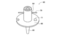
- the suction nozzle 60 includes a body cylinder 64, a flange portion 66, a suction pipe 68, and a latch pin 70.
- the body cylinder 64 has a cylindrical shape, and the flange portion 66 is fixed so as to overhang the outer peripheral surface of the body cylinder 64.
- a 2D code 71 is marked on the upper surface of the flange portion 66.
- the 2D code 71 is an identification symbol for identifying unique information of the suction nozzle 60.
- the suction pipe 68 has a thin pipe shape, and is held by the trunk cylinder 64 so as to be movable in the axial direction while extending downward from the lower end portion of the trunk cylinder 64.
- the latch pin 70 is provided at the upper end portion of the trunk cylinder 64 so as to extend in the radial direction of the trunk cylinder 64.
- the suction nozzle 60 is detachably attached to the mounting head 26 using the latch pin 70 with one touch.
- the suction nozzle 60 communicates with a positive / negative pressure supply device (not shown) via negative pressure air and positive pressure air passages.
- a positive / negative pressure supply device (not shown) via negative pressure air and positive pressure air passages.
- Each suction nozzle 60 sucks and holds the electronic component with a negative pressure, and detaches the held electronic component with a positive pressure.
- the mounting head 26 has a nozzle lifting / lowering device (not shown) that lifts and lowers the suction nozzle 60. The mounting head 26 changes the vertical position of the electronic component to be held by the nozzle lifting device.
- the supply device 28 is a feeder-type supply device, and is disposed at the front end of the frame portion 32 as shown in FIG.
- the supply device 28 has a tape feeder 72.
- the tape feeder 72 accommodates the taped component in a wound state.
- the taped component is a taped electronic component.
- the tape feeder 72 sends out the taped parts by a delivery device (not shown).
- the feeder type supply device 28 supplies the electronic component at the supply position by feeding the taped component.
- the nozzle station 30 has a nozzle tray 76 that houses a plurality of suction nozzles 60.
- exchange of the suction nozzle 60 attached to the mounting head 26 and the suction nozzle 60 accommodated in the nozzle tray 76 is performed as necessary.
- the nozzle tray 76 can be attached to and detached from the nozzle station 30, and the collection of the suction nozzle 60 accommodated in the nozzle tray 76 and the replenishment of the suction nozzle 60 to the nozzle tray 76 can be performed outside the mounting machine 14. Is possible.
- the mounting operation can be performed by the mounting head 26 on the circuit board held by the transport device 22 with the above-described configuration.
- the circuit board is transported to the work position according to a command from a control device (not shown) of the mounting machine 14, and is fixedly held by the board holding device at that position.
- the tape feeder 72 sends out the taped parts and supplies the electronic parts at the supply position in accordance with a command from the control device.
- the mounting head 26 moves above the supply position of the electronic component and sucks and holds the electronic component by the suction nozzle 60. Subsequently, the mounting head 26 moves above the circuit board and mounts the held electronic component on the circuit board.
- the electronic component supplied by the tape feeder 72 is sucked and held by the suction nozzle 60, and the electronic component is mounted on the circuit board.
- foreign matters such as solder may adhere to the suction nozzle 60, and an appropriate mounting operation cannot be performed with the suction nozzle 60 to which foreign matter has adhered.
- the nozzle tray 76 is removed from the nozzle station 30 of the mounting machine 14, and the suction nozzle 60 accommodated in the nozzle tray 76 is cleaned in the nozzle management device.
- the nozzle management device will be described in detail.
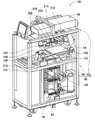
- the nozzle management device 80 has a generally rectangular parallelepiped shape.
- the nozzle management device 80 accommodates the nozzle tray 76 in the nozzle management device 80 on the front or takes out the nozzle tray 76 from the nozzle management device 80.
- a door 82 is provided above the door 82. Above the door 82, a panel 86 for displaying various information, an operation switch 88 for inputting information and the like are disposed.
- the nozzle management device 80 has a management device main body 90, a pallet storage device 92, a nozzle cleaning device 94, and a nozzle transfer device 96.
- FIG. 4 is a perspective view showing a state in which the outer shell member of the nozzle management device 80 is removed, and shows the internal structure of the nozzle management device 80.
- the management device main body 90 includes a frame unit 100 and a beam unit 102 that is overlaid on the frame unit 100.
- the frame portion 100 has a hollow structure, and the pallet accommodating device 92 is disposed inside the frame portion 100 with the upper end portion of the pallet accommodating device 92 exposed on the upper surface of the frame portion 100.
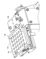
- the pallet storage device 92 is a device for storing the nozzle pallet 110 shown in FIG.
- a plurality of mounting holes 112 are formed in the nozzle pallet 110.
- the mounting hole 112 is a stepped through hole, and the suction nozzle 60 can be mounted on the mounting hole 112.
- the inner diameter of the step surface 114 of the stepped mounting hole 112 is slightly larger than the outer diameter of the flange portion 66 of the suction nozzle 60, and the flange portion 66 of the suction nozzle 60 is placed on the step surface 114. Is done.
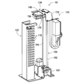
- the pallet accommodating device 92 is a device that accommodates the nozzle pallet 110 having the above structure. As shown in FIG. 7, the pallet accommodating device 92 has a pallet moving device 130 and a pallet accommodating tower 132, and the pallet moving device 130 and the pallet accommodating tower 132 are arranged so as to face each other. ing.
- the pallet moving device 130 includes a support arm 134 and an arm moving mechanism 136.
- the support arm 134 is generally U-shaped, and the end on the opening side functions as a tip. That is, the distal end portion of the support arm 134 extends in a bifurcated manner. Further, the distance between the tip portions of the support arm 134 that extends into the fork is smaller than the width of the nozzle pallet 110. Therefore, as shown in FIG. 5, the nozzle pallet 110 is placed on the upper surface of the support arm 134. Further, as shown in FIG. 7, a reflection plate 148 is attached to the lower surface side of the support arm 134.
- the arm moving mechanism 136 includes a base 150, an upper cover 152, a guide rail 154, a screw mechanism 156, and a slider 158.
- the guide rail 154 is disposed so as to extend in the vertical direction, and is fixed to the base 150 at the lower end.
- An upper cover 152 is fixed to the upper end portion of the guide rail 154.
- the screw mechanism 156 includes a screw rod 162 and a nut (not shown).
- a male screw (not shown) is formed on the outer peripheral surface of the screw rod 162, and the screw rod 162 is disposed in parallel with the guide rail 154 so as to extend in the vertical direction.
- the rod 162 is held by the base 150 and the upper cover 152 so as to be rotatable around its axis.
- the screw rod 162 rotates around the axis in a controllable manner by driving an electromagnetic motor (not shown).
- the nut is screwed into a male screw formed on the outer peripheral surface of the screw rod 162 and is fixed to the slider 158.
- the slider 158 is formed with a through hole (not shown) penetrating in the vertical direction.
- the guide rail 154 is inserted through the through hole, and the slider 158 moves along the guide rail 154.
- the screw rod 162 is rotated by driving of the electromagnetic motor, so that the slider 158 moves along the guide rail 154 to an arbitrary position in the vertical direction. Note that the upper end portion of the pallet moving device 130 is exposed on the upper surface of the frame portion 100.
- a support arm 134 is arranged on the upper surface of the slider 158 so as to be slidable in the front-rear direction. As a result, the support arm 134 approaches / separates toward the pallet accommodation tower 132. The support arm 134 slides to an arbitrary position by driving an electromagnetic motor (not shown).
- the pallet storage tower 132 is formed with a plurality of pallet storage portions 170.
- the plurality of pallet storage units 170 are arranged in the vertical direction, and the nozzle pallet 110 is stored in each pallet storage unit 170.
- the nozzle cleaning device 94 is a device for cleaning and drying the suction nozzle 60, and is disposed on the upper surface of the frame portion 100 as shown in FIG.
- the nozzle cleaning device 94 includes a cleaning / drying mechanism 180 and a cleaning pallet moving mechanism 182.
- the cleaning / drying mechanism 180 is a mechanism for cleaning and drying the suction nozzle 60 inside.
- the cleaning pallet moving mechanism 182 moves the cleaning pallet 186 between an exposure position where the cleaning pallet 186 is exposed (a position where the cleaning pallet 186 is illustrated in FIG. 4) and the cleaning / drying mechanism 180. It is.
- the cleaning pallet 186 has a plurality of mounting holes 188 having the same shape as the mounting hole 112 of the nozzle pallet 110, and the suction nozzle 60 can be mounted on the cleaning pallet 186.
- the nozzle transfer device 96 is a device for transferring the suction nozzle 60, and is disposed in the beam unit 102.
- the nozzle transfer device 96 includes a transfer head 200 and a head moving device 202.
- a camera 206 facing downward, a holding chuck 208 for holding the suction nozzle 60, and an air ejector 210 for ejecting air downward are attached.
- the head moving device 202 is an XYZ type moving device that moves the transfer head 200 in the front-rear direction, the left-right direction, and the up-down direction on the frame unit 100.
- a fixed stage 212 for setting the nozzle tray 76 is provided on the upper surface of the frame unit 100.
- the nozzle tray 76 set on the fixed stage 212, the nozzle pallet 110 supported by the support arm 134, and The suction nozzle 60 is transferred to and from the cleaning pallet 186 located at the exposure position.
- the suction nozzle 60 is cleaned, and the suction nozzle 60 after cleaning is stored in the pallet storage tower 132.
- the operator sets the nozzle tray 76 on which the suction nozzle 60 is mounted on the fixed stage 212.
- the holding chuck 208 of the nozzle transfer device 96 moves above the nozzle tray 76 by the operation of the head moving device 202, and the suction nozzle 60 mounted on the nozzle tray 76 is held by the holding chuck 208.
- the holding chuck 208 When the suction nozzle 60 is held by the holding chuck 208, the holding chuck 208 is moved above the exposed position of the cleaning pallet moving mechanism 182 by the operation of the head moving device 202. At this time, in the cleaning pallet moving mechanism 182, the cleaning pallet 186 is moved to the exposure position by the operation of the cleaning pallet moving mechanism 182. Then, the holding chuck 208 moves downward, and the suction nozzle 60 is mounted on the cleaning pallet 186. When the mounting of the suction nozzle 60 on the cleaning pallet 186 is completed, the cleaning pallet 186 is moved into the cleaning / drying mechanism 180 by the operation of the cleaning pallet moving mechanism 182. Then, the suction nozzle 60 is cleaned and dried inside the cleaning / drying mechanism 180.
- the cleaning pallet 186 is moved to the exposure position by the operation of the cleaning pallet moving mechanism 182. Then, the holding chuck 208 is moved above the cleaning pallet 186 by the operation of the head moving device 202, and the suction nozzle 60 after cleaning is held by the holding chuck 208. Subsequently, the holding chuck 208 is moved above the pallet moving device 130 by the operation of the head moving device 202. At this time, in the pallet moving device 130, the support arm 134 that supports the nozzle pallet 110 is moved upward most by the operation of the screw mechanism 156.
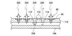
- the mounting hole 112 where the suction nozzle 60 is not mounted is detected. That is, it is determined whether or not the suction nozzle 60 is already mounted in the mounting hole 112 of the nozzle pallet 110. Specifically, as described above, the reflection plate 148 is disposed below the support arm 134 that supports the nozzle pallet 110. Further, the mounting hole 112 of the nozzle pallet 110 passes therethrough. Therefore, as shown in FIG. 6, when the suction nozzle 60 is not placed in the placement hole 112 of the nozzle pallet 110, the irradiation light 220 from above the nozzle pallet 110 passes through the placement hole 112.
- the suction nozzle 60 is placed in the placement hole 112
- the irradiation light 222 from above the nozzle pallet 110 is blocked by the suction nozzle 60 and is not reflected by the reflector 148. Therefore, when the nozzle pallet 110 supported by the support arm 134 is imaged from above by the camera 206 and the reflected light is included in the imaging data of the placement hole 112 of the nozzle pallet 110, the placement hole 112 is captured. It is possible to determine that the suction nozzle 60 is not placed on the surface. On the other hand, when the reflected light is not included in the imaging data of the placement hole 112, it can be determined that the suction nozzle 60 is placed in the placement hole 112.
- the suction nozzle 60 mounted on the nozzle pallet 110 is dried after cleaning in the cleaning / drying mechanism 180, but in the cleaning / drying mechanism 180, the suction nozzle 60 is mounted on the cleaning pallet 186. Since drying is performed, there is a possibility that moisture adheres to the suction nozzle 60. For this reason, the water adhering to the suction nozzle 60 falls to the nozzle pallet 110, the dropped water droplets adhere to the reflector 148, and whether or not the suction nozzle 60 is placed in the placement hole 112 by the water drops. May not be properly determined.
- water droplets 226 are attached to the reflector 148, and when light is irradiated from above the nozzle pallet 110 toward the water droplets, the irradiation light 228 is caused by the water droplets 226. It may be refracted and not regularly reflected. In such a case, even if the suction nozzle 60 is not mounted in the mounting hole 112 of the nozzle pallet 110, the reflected light is not included in the imaging data of the mounting hole 112. That is, when the suction nozzle 60 is not mounted in the mounting hole 112 of the nozzle pallet 110, it is erroneously determined that the suction nozzle 60 is mounted in the mounting hole 112.
- the air ejector 210 causes the mounting hole 112 to be mounted. After air is jetted out, whether or not the suction nozzle 60 is mounted in the mounting hole 112 is determined again. Specifically, when it is determined that the suction nozzle 60 is mounted in the mounting hole 112 based on the imaging data of the mounting hole 112, the air ejector 210 is operated by the operation of the head moving device 202. Then, it moves above the mounting hole 112 to be determined. Subsequently, air is ejected by the air ejector 210 toward the mounting hole 112 to be determined.
- the camera 206 re-images the nozzle pallet 110 and re-determines whether the suction nozzle 60 is mounted in the mounting hole 112 based on the image data. That is, after the water droplet 226 that causes an erroneous determination is blown off, whether or not the suction nozzle 60 is mounted in the mounting hole 112 is determined again. Thereby, it is possible to appropriately determine whether or not the suction nozzle 60 is mounted in the mounting hole 112.
- the suction nozzle 60 When it is determined whether or not the suction nozzle 60 is mounted in the mounting hole 112 according to the above procedure, the suction nozzle 60 is held above the mounting hole 112 determined that the suction nozzle 60 is not mounted.
- the chuck 208 is moved by the operation of the head moving device 202, and the suction nozzle 60 is mounted in the mounting hole 112.
- the support arm 134 that supports the nozzle pallet 110 is lowered by the operation of the screw mechanism 156. At this time, the support arm 134 is lowered so that the nozzle pallet 110 supported by the support arm 134 faces the pallet storage unit 170 to be stored. Then, the support arm 134 moves in a direction approaching the pallet accommodation tower 132. Thereby, the nozzle pallet 110 supported by the support arm 134 is accommodated in the pallet accommodating part 170 to be accommodated.
- the suction nozzle 60 is an example of a suction nozzle.
- the 2D code 71 is an example of an identification symbol.
- the mounting hole 112 is an example of a nozzle storage unit.
- the reflection plate 148 is an example of a reflection member.
- a step of determining whether or not the suction nozzle 60 is mounted in the mounting hole 112 based on the image data captured by the camera 206 is an example of a determination step.
- the step of ejecting air toward the placement hole 112 by the air ejector 210 after it is determined that the suction nozzle 60 is not mounted in the placement hole 112 is an example of the air ejection step.
- the step of re-determining whether or not the suction nozzle 60 is mounted in the mounting hole 112 based on the image data captured by the camera 206 after the air is ejected toward the mounting hole 112 is an example of a redetermination step. It is.
- the present invention is not limited to the above-described embodiments, and can be implemented in various modes with various changes and improvements based on the knowledge of those skilled in the art. Specifically, for example, in the above-described embodiment, whether or not the suction nozzle 60 is mounted in the mounting hole 112 is determined using the reflected light from the reflection plate 148. It is possible to determine whether or not the suction nozzle 60 is mounted in the mounting hole 112 using the identification symbol.
- the mounting hole 112 of the nozzle pallet 110 is imaged by the camera 206, and it is determined whether or not the data related to the 2D code 71 of the suction nozzle 60 is included in the imaging data. If the data related to the 2D code 71 of the suction nozzle 60 is included in the imaging data, it is determined that the suction nozzle 60 is mounted in the mounting hole 112, and the data related to the 2D code 71 of the suction nozzle 60 is included in the imaging data. Is not included, it is determined that the suction nozzle 60 is not mounted in the mounting hole 112. At this time, if it is determined that the suction nozzle 60 is not mounted in the mounting hole 112, the air ejector 210 ejects air toward the mounting hole 112.
- the mounting hole 112 of the nozzle pallet 110 is imaged by the camera 206, and it is determined whether or not the data related to the 2D code 71 of the suction nozzle 60 is included in the imaging data. As a result, it is possible to appropriately determine whether or not the suction nozzle 60 is mounted in the mounting hole 112 after blowing off dust, water droplets, or the like that cause erroneous determination.
- whether or not the suction nozzle 60 is mounted in the mounting hole 112 is determined using the image data obtained by the camera 206.
- the mounting of the suction nozzle 60 is performed using an optical sensor. It is possible to determine whether or not the hole 112 is mounted. Specifically, for example, when the distance between the sensor placement position and the mounting hole 112 is measured by a distance sensor, the measurement distance when the suction nozzle 60 is mounted in the mounting hole 112. Is shorter than the measurement distance when the suction nozzle 60 is not mounted in the mounting hole 112. Using this fact, it is possible to determine whether or not the suction nozzle 60 is mounted in the mounting hole 112.
- the nozzle management device 80 inspects whether or not the suction nozzle 60 is mounted on the nozzle pallet 110, but the mounting machine 14 determines whether or not the suction nozzle 60 is mounted on the nozzle tray 76. It is possible to inspect.
- Adsorption nozzle 71 2D code (identification symbol) 112: Placement hole (nozzle storage part) 148: Reflecting plate (reflecting member)
Landscapes
- Engineering & Computer Science (AREA)
- Physics & Mathematics (AREA)
- General Physics & Mathematics (AREA)
- Manufacturing & Machinery (AREA)
- Microelectronics & Electronic Packaging (AREA)
- Quality & Reliability (AREA)
- Computer Vision & Pattern Recognition (AREA)
- Theoretical Computer Science (AREA)
- Supply And Installment Of Electrical Components (AREA)
Abstract
Description
図1に、電子部品装着装置(以下、「装着装置」と略す場合がある)10を示す。装着装置10は、1つのシステムベース12と、そのシステムベース12の上に隣接された2台の電子部品装着機(以下、「装着機」と略す場合がある)14とを有している。なお、装着機14の並ぶ方向をX軸方向と称し、その方向に直角な水平の方向をY軸方向と称する。
装着機14では、上述した構成によって、搬送装置22に保持された回路基板に対して、装着ヘッド26によって装着作業を行うことが可能である。具体的には、装着機14の制御装置(図示省略)の指令により、回路基板が作業位置まで搬送され、その位置において、基板保持装置によって固定的に保持される。また、テープフィーダ72は、制御装置の指令により、テープ化部品を送り出し、電子部品を供給位置において供給する。そして、装着ヘッド26が、電子部品の供給位置の上方に移動し、吸着ノズル60によって電子部品を吸着保持する。続いて、装着ヘッド26は、回路基板の上方に移動し、保持している電子部品を回路基板上に装着する。
ノズル管理装置80は、図3に示すように、概して直方体形状をなしており、正面に、ノズルトレイ76をノズル管理装置80内に収納、若しくは、ノズル管理装置80からノズルトレイ76を取り出すための扉82が設けられている。その扉82の上方には、各種情報を表示するパネル86、情報等の入力を行うための操作スイッチ88等が配設されている。
管理装置本体90は、フレーム部100と、そのフレーム部100に上架されたビーム部102とによって構成されている。フレーム部100は、中空構造とされており、フレーム部100の上面にパレット収容装置92の上端部が露出した状態で、パレット収容装置92がフレーム部100の内部に配設されている。
パレット収容装置92は、図5に示すノズルパレット110を収容する装置である。ノズルパレット110には、複数の載置穴112が形成されている。載置穴112は、図6に示すように、段付形状の貫通穴であり、吸着ノズル60を載置することが可能である。詳しくは、段付形状の載置穴112の段差面114の内径は、吸着ノズル60のフランジ部66の外径より僅かに大きく、その段差面114に、吸着ノズル60のフランジ部66が載置される。
ノズル洗浄装置94は、吸着ノズル60の洗浄および乾燥を行う装置であり、図4に示すように、フレーム部100の上面に配設されている。ノズル洗浄装置94は、洗浄・乾燥機構180と洗浄パレット移動機構182とを備えている。洗浄・乾燥機構180は、内部において吸着ノズル60の洗浄および乾燥を行う機構である。洗浄パレット移動機構182は、洗浄パレット186が露出する露出位置(図4で洗浄パレット186が図示されている位置)と、洗浄・乾燥機構180の内部との間で、洗浄パレット186を移動させる機構である。なお、洗浄パレット186には、ノズルパレット110の載置穴112と同形状の載置穴188が複数形成されており、洗浄パレット186上に、吸着ノズル60を載置することが可能である。
ノズル移載装置96は、吸着ノズル60を移載するための装置であり、ビーム部102に配設されている。ノズル移載装置96は、移載ヘッド200とヘッド移動装置202とを有している。移載ヘッド200の下端面には、下方を向いた状態のカメラ206と、吸着ノズル60を保持するための保持チャック208と、下方に向かってエアを噴出するエア噴出器210とが取り付けられている。また、ヘッド移動装置202は、移載ヘッド200をフレーム部100の上において前後方向、左右方向、上下方向に移動させるXYZ型の移動装置である。
上述した構造のノズル管理装置80では、吸着ノズル60の洗浄が行われ、洗浄後の吸着ノズル60がパレット収容タワー132に収納される。詳しくは、作業者は、吸着ノズル60が搭載されたノズルトレイ76を、固定ステージ212にセットする。そして、ノズル移載装置96の保持チャック208が、ヘッド移動装置202の作動により、ノズルトレイ76の上方に移動し、ノズルトレイ76に搭載された吸着ノズル60が、保持チャック208によって保持される。
Claims (4)
- 吸着ノズルがノズル収納部に収納されているか否かを検査する検査方法において、
当該検査方法が、
吸着ノズルが前記ノズル収納部に収納されているか否かを判定する判定工程と、
前記判定工程により吸着ノズルが前記ノズル収納部に収納されていると判定された場合に、前記収納部に向かってエアを噴出するエア噴出工程と、
前記エア噴出工程によりエアを噴出した後に、吸着ノズルが前記ノズル収納部に収納されているか否かを判定する再判定工程と
を含むことを特徴とする検査方法。 - 前記判定工程と前記再判定工程との各々が、
前記ノズル収納部を撮像し、撮像により得られた撮像データに基づいて、吸着ノズルが前記ノズル収納部に収納されているか否かを判定する工程であることを特徴とする請求項1に記載の検査方法。 - 前記ノズル収納部が、
上下方向に貫通するとともに、吸着ノズルが収容された際にその吸着ノズルによって塞がれる貫通穴を有し、
前記貫通穴の下方に、反射部材が設けられており、
前記判定工程と前記再判定工程との各々が、
撮像により得られた撮像データに、前記反射部材による反射光が含まれない場合に、吸着ノズルが前記ノズル収納部に収納されていると判定し、前記反射部材による反射光が含まれる場合に、吸着ノズルが前記ノズル収納部に収納されていないと判定する工程であることを特徴とする請求項2に記載の検査方法。 - 前記判定工程と前記再判定工程との各々が、
撮像により得られた撮像データに、吸着ノズルに記された識別記号が含まれる場合に、吸着ノズルが前記ノズル収納部に収納されていると判定し、前記識別記号が含まれない場合に、吸着ノズルが前記ノズル収納部に収納されていないと判定する工程であることを特徴とする請求項2に記載の検査方法。
Priority Applications (5)
| Application Number | Priority Date | Filing Date | Title |
|---|---|---|---|
| JP2016535604A JP6356245B2 (ja) | 2014-07-25 | 2014-07-25 | 検査方法 |
| CN201480080790.7A CN106576438B (zh) | 2014-07-25 | 2014-07-25 | 检查吸嘴是否收纳于吸嘴收纳部的检查方法 |
| EP14898164.0A EP3174377B1 (en) | 2014-07-25 | 2014-07-25 | Inspection method |
| PCT/JP2014/069660 WO2016013103A1 (ja) | 2014-07-25 | 2014-07-25 | 検査方法 |
| US15/320,672 US10217206B2 (en) | 2014-07-25 | 2014-07-25 | Inspection method |
Applications Claiming Priority (1)
| Application Number | Priority Date | Filing Date | Title |
|---|---|---|---|
| PCT/JP2014/069660 WO2016013103A1 (ja) | 2014-07-25 | 2014-07-25 | 検査方法 |
Publications (1)
| Publication Number | Publication Date |
|---|---|
| WO2016013103A1 true WO2016013103A1 (ja) | 2016-01-28 |
Family
ID=55162657
Family Applications (1)
| Application Number | Title | Priority Date | Filing Date |
|---|---|---|---|
| PCT/JP2014/069660 Ceased WO2016013103A1 (ja) | 2014-07-25 | 2014-07-25 | 検査方法 |
Country Status (5)
| Country | Link |
|---|---|
| US (1) | US10217206B2 (ja) |
| EP (1) | EP3174377B1 (ja) |
| JP (1) | JP6356245B2 (ja) |
| CN (1) | CN106576438B (ja) |
| WO (1) | WO2016013103A1 (ja) |
Families Citing this family (5)
| Publication number | Priority date | Publication date | Assignee | Title |
|---|---|---|---|---|
| JP2747843B2 (ja) | 1990-04-05 | 1998-05-06 | 信越化学工業株式会社 | 塩化ビニル系重合体の製造方法 |
| US10292319B2 (en) * | 2014-04-22 | 2019-05-14 | Fuji Corporation | Load measurement method and collection method |
| WO2017068661A1 (ja) * | 2015-10-21 | 2017-04-27 | 富士機械製造株式会社 | ノズル管理装置およびノズル管理装置の制御方法 |
| JP2017130594A (ja) * | 2016-01-22 | 2017-07-27 | 富士機械製造株式会社 | 検査方法 |
| CN116615965B (zh) * | 2020-12-11 | 2025-02-25 | 株式会社富士 | 吸嘴及元件装配机 |
Citations (3)
| Publication number | Priority date | Publication date | Assignee | Title |
|---|---|---|---|---|
| JP2003101292A (ja) * | 2001-09-19 | 2003-04-04 | Matsushita Electric Ind Co Ltd | 部品実装方法及びその装置 |
| JP2010034571A (ja) * | 2009-09-30 | 2010-02-12 | Fuji Mach Mfg Co Ltd | 電子回路部品装着機 |
| JP2010073766A (ja) * | 2008-09-17 | 2010-04-02 | Juki Corp | 表面実装機におけるノズル交換装置のノズル有無検出方法及び装置 |
Family Cites Families (14)
| Publication number | Priority date | Publication date | Assignee | Title |
|---|---|---|---|---|
| JP3301304B2 (ja) * | 1996-03-28 | 2002-07-15 | 松下電器産業株式会社 | 電子部品実装装置および電子部品実装装置におけるノズル交換方法 |
| JPH1068759A (ja) * | 1996-05-31 | 1998-03-10 | Advantest Corp | 吸着物検知装置、該装置を用いた吸着物検知方法、該装置を用いた位置ずれ検知方法、および該装置を用いた清掃方法 |
| JP4445087B2 (ja) * | 2000-03-22 | 2010-04-07 | Juki株式会社 | 画像認識装置の清掃方法 |
| JP2005347317A (ja) * | 2004-05-31 | 2005-12-15 | Yamaha Motor Co Ltd | 部品供給装置およびそれを備えた実装機 |
| JP4520288B2 (ja) * | 2004-12-08 | 2010-08-04 | ヤマハ発動機株式会社 | 部品搬送装置、表面実装機および部品試験装置 |
| JP2007035872A (ja) * | 2005-07-26 | 2007-02-08 | Yamaha Motor Co Ltd | 清掃方法および表面実装機 |
| JP4851361B2 (ja) * | 2007-02-19 | 2012-01-11 | 富士機械製造株式会社 | 電子回路部品装着装置 |
| JP4849057B2 (ja) * | 2007-11-09 | 2011-12-28 | パナソニック株式会社 | 電子部品実装装置およびノズル装着履歴データ管理方法 |
| JP2010087040A (ja) * | 2008-09-29 | 2010-04-15 | Juki Corp | 表面実装機のノズル交換ユニット検査方法及び装置 |
| JP4592809B2 (ja) | 2009-07-06 | 2010-12-08 | 富士機械製造株式会社 | 電子回路部品装着機 |
| JP5670725B2 (ja) * | 2010-12-28 | 2015-02-18 | 富士機械製造株式会社 | 電子部品割振方法および電子部品実装方法 |
| JP5791408B2 (ja) * | 2011-07-15 | 2015-10-07 | 富士機械製造株式会社 | 電子部品実装装置 |
| JP6161022B2 (ja) * | 2012-05-08 | 2017-07-12 | 富士機械製造株式会社 | 吸着ノズル検査装置 |
| CN102826383B (zh) * | 2012-10-08 | 2014-06-25 | 深圳市景颢光电科技有限公司 | 一种取放料组件 |
-
2014
- 2014-07-25 JP JP2016535604A patent/JP6356245B2/ja active Active
- 2014-07-25 EP EP14898164.0A patent/EP3174377B1/en active Active
- 2014-07-25 WO PCT/JP2014/069660 patent/WO2016013103A1/ja not_active Ceased
- 2014-07-25 CN CN201480080790.7A patent/CN106576438B/zh active Active
- 2014-07-25 US US15/320,672 patent/US10217206B2/en active Active
Patent Citations (3)
| Publication number | Priority date | Publication date | Assignee | Title |
|---|---|---|---|---|
| JP2003101292A (ja) * | 2001-09-19 | 2003-04-04 | Matsushita Electric Ind Co Ltd | 部品実装方法及びその装置 |
| JP2010073766A (ja) * | 2008-09-17 | 2010-04-02 | Juki Corp | 表面実装機におけるノズル交換装置のノズル有無検出方法及び装置 |
| JP2010034571A (ja) * | 2009-09-30 | 2010-02-12 | Fuji Mach Mfg Co Ltd | 電子回路部品装着機 |
Also Published As
| Publication number | Publication date |
|---|---|
| EP3174377B1 (en) | 2020-08-26 |
| EP3174377A1 (en) | 2017-05-31 |
| US10217206B2 (en) | 2019-02-26 |
| JP6356245B2 (ja) | 2018-07-11 |
| CN106576438B (zh) | 2019-06-25 |
| EP3174377A4 (en) | 2018-03-21 |
| CN106576438A (zh) | 2017-04-19 |
| JPWO2016013103A1 (ja) | 2017-04-27 |
| US20170213332A1 (en) | 2017-07-27 |
Similar Documents
| Publication | Publication Date | Title |
|---|---|---|
| JP6408005B2 (ja) | ノズル収納庫 | |
| CN105265036B (zh) | 吸嘴管理系统 | |
| JP6356245B2 (ja) | 検査方法 | |
| CN107615910B (zh) | 附着物去除方法及附着物去除装置 | |
| CN101715287A (zh) | 表面安装机的吸附嘴更换单元检查方法及装置 | |
| CN114175872B (zh) | 吸嘴的检查装置和吸嘴的检查方法 | |
| JP6574842B2 (ja) | 制御装置 | |
| JP2017130594A (ja) | 検査方法 | |
| JP2017130595A (ja) | ノズル収納庫 | |
| US12392553B2 (en) | Drying device and drying method | |
| JP2020123749A (ja) | ノズル管理装置 | |
| JP6830329B2 (ja) | 検査装置、および検査方法 | |
| JP6703061B2 (ja) | ノズル収納庫 | |
| WO2019244196A1 (ja) | 吸着ノズル管理装置と吸着ノズル管理方法 | |
| JP7011441B2 (ja) | 実装装置及び実装方法 | |
| JP7263618B2 (ja) | 乾燥装置、およびノズル乾燥方法 | |
| JP6785214B2 (ja) | 検査装置、および検査方法 | |
| CN110447318B (zh) | 工具管理装置 |
Legal Events
| Date | Code | Title | Description |
|---|---|---|---|
| 121 | Ep: the epo has been informed by wipo that ep was designated in this application |
Ref document number: 14898164 Country of ref document: EP Kind code of ref document: A1 |
|
| ENP | Entry into the national phase |
Ref document number: 2016535604 Country of ref document: JP Kind code of ref document: A |
|
| WWE | Wipo information: entry into national phase |
Ref document number: 15320672 Country of ref document: US |
|
| REEP | Request for entry into the european phase |
Ref document number: 2014898164 Country of ref document: EP |
|
| WWE | Wipo information: entry into national phase |
Ref document number: 2014898164 Country of ref document: EP |
|
| NENP | Non-entry into the national phase |
Ref country code: DE |