WO2016013196A1 - トリガー式ポンプディスペンサ - Google Patents
トリガー式ポンプディスペンサ Download PDFInfo
- Publication number
- WO2016013196A1 WO2016013196A1 PCT/JP2015/003624 JP2015003624W WO2016013196A1 WO 2016013196 A1 WO2016013196 A1 WO 2016013196A1 JP 2015003624 W JP2015003624 W JP 2015003624W WO 2016013196 A1 WO2016013196 A1 WO 2016013196A1
- Authority
- WO
- WIPO (PCT)
- Prior art keywords
- trigger
- piston
- pump dispenser
- type pump
- housing
- Prior art date
- Legal status (The legal status is an assumption and is not a legal conclusion. Google has not performed a legal analysis and makes no representation as to the accuracy of the status listed.)
- Ceased
Links
Images


Classifications
-
- B—PERFORMING OPERATIONS; TRANSPORTING
- B05—SPRAYING OR ATOMISING IN GENERAL; APPLYING FLUENT MATERIALS TO SURFACES, IN GENERAL
- B05B—SPRAYING APPARATUS; ATOMISING APPARATUS; NOZZLES
- B05B11/00—Single-unit hand-held apparatus in which flow of contents is produced by the muscular force of the operator at the moment of use
- B05B11/01—Single-unit hand-held apparatus in which flow of contents is produced by the muscular force of the operator at the moment of use characterised by the means producing the flow
- B05B11/10—Pump arrangements for transferring the contents from the container to a pump chamber by a sucking effect and forcing the contents out through the dispensing nozzle
- B05B11/1001—Piston pumps
- B05B11/1009—Piston pumps actuated by a lever
- B05B11/1011—Piston pumps actuated by a lever without substantial movement of the nozzle in the direction of the pressure stroke
-
- B—PERFORMING OPERATIONS; TRANSPORTING
- B05—SPRAYING OR ATOMISING IN GENERAL; APPLYING FLUENT MATERIALS TO SURFACES, IN GENERAL
- B05B—SPRAYING APPARATUS; ATOMISING APPARATUS; NOZZLES
- B05B11/00—Single-unit hand-held apparatus in which flow of contents is produced by the muscular force of the operator at the moment of use
- B05B11/01—Single-unit hand-held apparatus in which flow of contents is produced by the muscular force of the operator at the moment of use characterised by the means producing the flow
- B05B11/10—Pump arrangements for transferring the contents from the container to a pump chamber by a sucking effect and forcing the contents out through the dispensing nozzle
- B05B11/1042—Components or details
- B05B11/1043—Sealing or attachment arrangements between pump and container
- B05B11/1045—Sealing or attachment arrangements between pump and container the pump being preassembled as an independent unit before being mounted on the container
-
- B—PERFORMING OPERATIONS; TRANSPORTING
- B05—SPRAYING OR ATOMISING IN GENERAL; APPLYING FLUENT MATERIALS TO SURFACES, IN GENERAL
- B05B—SPRAYING APPARATUS; ATOMISING APPARATUS; NOZZLES
- B05B11/00—Single-unit hand-held apparatus in which flow of contents is produced by the muscular force of the operator at the moment of use
- B05B11/01—Single-unit hand-held apparatus in which flow of contents is produced by the muscular force of the operator at the moment of use characterised by the means producing the flow
- B05B11/10—Pump arrangements for transferring the contents from the container to a pump chamber by a sucking effect and forcing the contents out through the dispensing nozzle
- B05B11/1042—Components or details
- B05B11/1052—Actuation means
- B05B11/1056—Actuation means comprising rotatable or articulated levers
- B05B11/1057—Triggers, i.e. actuation means consisting of a single lever having one end rotating or pivoting around an axis or a hinge fixedly attached to the container, and another end directly actuated by the user
-
- B—PERFORMING OPERATIONS; TRANSPORTING
- B05—SPRAYING OR ATOMISING IN GENERAL; APPLYING FLUENT MATERIALS TO SURFACES, IN GENERAL
- B05B—SPRAYING APPARATUS; ATOMISING APPARATUS; NOZZLES
- B05B11/00—Single-unit hand-held apparatus in which flow of contents is produced by the muscular force of the operator at the moment of use
- B05B11/01—Single-unit hand-held apparatus in which flow of contents is produced by the muscular force of the operator at the moment of use characterised by the means producing the flow
- B05B11/10—Pump arrangements for transferring the contents from the container to a pump chamber by a sucking effect and forcing the contents out through the dispensing nozzle
- B05B11/1042—Components or details
- B05B11/1059—Means for locking a pump or its actuation means in a fixed position
-
- B—PERFORMING OPERATIONS; TRANSPORTING
- B05—SPRAYING OR ATOMISING IN GENERAL; APPLYING FLUENT MATERIALS TO SURFACES, IN GENERAL
- B05B—SPRAYING APPARATUS; ATOMISING APPARATUS; NOZZLES
- B05B11/00—Single-unit hand-held apparatus in which flow of contents is produced by the muscular force of the operator at the moment of use
- B05B11/01—Single-unit hand-held apparatus in which flow of contents is produced by the muscular force of the operator at the moment of use characterised by the means producing the flow
- B05B11/10—Pump arrangements for transferring the contents from the container to a pump chamber by a sucking effect and forcing the contents out through the dispensing nozzle
- B05B11/1042—Components or details
- B05B11/1066—Pump inlet valves
- B05B11/1067—Pump inlet valves actuated by pressure
-
- B—PERFORMING OPERATIONS; TRANSPORTING
- B05—SPRAYING OR ATOMISING IN GENERAL; APPLYING FLUENT MATERIALS TO SURFACES, IN GENERAL
- B05B—SPRAYING APPARATUS; ATOMISING APPARATUS; NOZZLES
- B05B11/00—Single-unit hand-held apparatus in which flow of contents is produced by the muscular force of the operator at the moment of use
- B05B11/01—Single-unit hand-held apparatus in which flow of contents is produced by the muscular force of the operator at the moment of use characterised by the means producing the flow
- B05B11/10—Pump arrangements for transferring the contents from the container to a pump chamber by a sucking effect and forcing the contents out through the dispensing nozzle
- B05B11/1042—Components or details
- B05B11/1073—Springs
- B05B11/1077—Springs characterised by a particular shape or material
-
- B—PERFORMING OPERATIONS; TRANSPORTING
- B05—SPRAYING OR ATOMISING IN GENERAL; APPLYING FLUENT MATERIALS TO SURFACES, IN GENERAL
- B05B—SPRAYING APPARATUS; ATOMISING APPARATUS; NOZZLES
- B05B11/00—Single-unit hand-held apparatus in which flow of contents is produced by the muscular force of the operator at the moment of use
- B05B11/01—Single-unit hand-held apparatus in which flow of contents is produced by the muscular force of the operator at the moment of use characterised by the means producing the flow
- B05B11/10—Pump arrangements for transferring the contents from the container to a pump chamber by a sucking effect and forcing the contents out through the dispensing nozzle
- B05B11/1094—Pump arrangements for transferring the contents from the container to a pump chamber by a sucking effect and forcing the contents out through the dispensing nozzle having inlet or outlet valves not being actuated by pressure or having no inlet or outlet valve
-
- F—MECHANICAL ENGINEERING; LIGHTING; HEATING; WEAPONS; BLASTING
- F04—POSITIVE - DISPLACEMENT MACHINES FOR LIQUIDS; PUMPS FOR LIQUIDS OR ELASTIC FLUIDS
- F04B—POSITIVE-DISPLACEMENT MACHINES FOR LIQUIDS; PUMPS
- F04B9/00—Piston machines or pumps characterised by the driving or driven means to or from their working members
- F04B9/14—Pumps characterised by muscle-power operation
-
- B—PERFORMING OPERATIONS; TRANSPORTING
- B05—SPRAYING OR ATOMISING IN GENERAL; APPLYING FLUENT MATERIALS TO SURFACES, IN GENERAL
- B05B—SPRAYING APPARATUS; ATOMISING APPARATUS; NOZZLES
- B05B11/00—Single-unit hand-held apparatus in which flow of contents is produced by the muscular force of the operator at the moment of use
- B05B11/0005—Components or details
- B05B11/0062—Outlet valves actuated by the pressure of the fluid to be sprayed
- B05B11/007—Outlet valves actuated by the pressure of the fluid to be sprayed being opened by deformation of a sealing element made of resiliently deformable material, e.g. flaps, skirts, duck-bill valves
-
- B—PERFORMING OPERATIONS; TRANSPORTING
- B05—SPRAYING OR ATOMISING IN GENERAL; APPLYING FLUENT MATERIALS TO SURFACES, IN GENERAL
- B05B—SPRAYING APPARATUS; ATOMISING APPARATUS; NOZZLES
- B05B11/00—Single-unit hand-held apparatus in which flow of contents is produced by the muscular force of the operator at the moment of use
- B05B11/0005—Components or details
- B05B11/0062—Outlet valves actuated by the pressure of the fluid to be sprayed
- B05B11/0075—Two outlet valves being placed in a delivery conduit, one downstream the other
-
- B—PERFORMING OPERATIONS; TRANSPORTING
- B05—SPRAYING OR ATOMISING IN GENERAL; APPLYING FLUENT MATERIALS TO SURFACES, IN GENERAL
- B05B—SPRAYING APPARATUS; ATOMISING APPARATUS; NOZZLES
- B05B11/00—Single-unit hand-held apparatus in which flow of contents is produced by the muscular force of the operator at the moment of use
- B05B11/01—Single-unit hand-held apparatus in which flow of contents is produced by the muscular force of the operator at the moment of use characterised by the means producing the flow
- B05B11/10—Pump arrangements for transferring the contents from the container to a pump chamber by a sucking effect and forcing the contents out through the dispensing nozzle
- B05B11/1038—Pressure accumulation pumps, i.e. pumps comprising a pressure accumulation chamber
- B05B11/104—Pressure accumulation pumps, i.e. pumps comprising a pressure accumulation chamber the outlet valve being opened by pressure after a defined accumulation stroke
-
- B—PERFORMING OPERATIONS; TRANSPORTING
- B05—SPRAYING OR ATOMISING IN GENERAL; APPLYING FLUENT MATERIALS TO SURFACES, IN GENERAL
- B05B—SPRAYING APPARATUS; ATOMISING APPARATUS; NOZZLES
- B05B11/00—Single-unit hand-held apparatus in which flow of contents is produced by the muscular force of the operator at the moment of use
- B05B11/01—Single-unit hand-held apparatus in which flow of contents is produced by the muscular force of the operator at the moment of use characterised by the means producing the flow
- B05B11/10—Pump arrangements for transferring the contents from the container to a pump chamber by a sucking effect and forcing the contents out through the dispensing nozzle
- B05B11/1042—Components or details
- B05B11/1043—Sealing or attachment arrangements between pump and container
- B05B11/1046—Sealing or attachment arrangements between pump and container the pump chamber being arranged substantially coaxially to the neck of the container
- B05B11/1047—Sealing or attachment arrangements between pump and container the pump chamber being arranged substantially coaxially to the neck of the container the pump being preassembled as an independent unit before being mounted on the container
-
- B—PERFORMING OPERATIONS; TRANSPORTING
- B05—SPRAYING OR ATOMISING IN GENERAL; APPLYING FLUENT MATERIALS TO SURFACES, IN GENERAL
- B05B—SPRAYING APPARATUS; ATOMISING APPARATUS; NOZZLES
- B05B15/00—Details of spraying plant or spraying apparatus not otherwise provided for; Accessories
- B05B15/60—Arrangements for mounting, supporting or holding spraying apparatus
- B05B15/63—Handgrips
Definitions
- the present invention relates to a trigger type pump dispenser for efficiently injecting a liquid contained in a container attached to the container.
- a trigger-type pump dispenser has been widely used as an instrument that is attached to a container and discharges or injects liquid inside.
- the trigger type pump dispenser is usually provided with a piston and a cylinder, and a liquid is injected by applying pressure into the cylinder by moving the piston.
- This trigger type pump dispenser is divided into types depending on how the piston is moved. As one of them, for example, there is a trigger type pump dispenser in which a trigger is pulled with four fingers (see Patent Document 1 and Patent Document 2).
- the trigger type pump dispenser described in Patent Document 3 has the following structure. That is, the structure of the trigger type pump dispenser described in Patent Document 3 is a trigger type pump dispenser that can be attached to a container, and is attached to a cylinder part, a piston structure that can slide in the cylinder part, and the cylinder part. A housing part formed integrally with the housing part, a trigger part attached to the housing part and connected to the piston structure via the crank part, and a cap for attaching the cylinder part to the container body It has.
- the piston structure has a flexible long nozzle part and a piston part, and by pushing down the trigger part and bringing it close to the handle part, the piston part is pushed down via the crank part and pressure is applied to the cylinder part. The liquid is discharged through the long nozzle part.
- the trigger type pump dispenser described in Patent Document 3 can solve the above-mentioned drawbacks of Patent Document 1 and Patent Document 2.
- the trigger type pump dispenser described in Patent Document 3 is excellent in operability because the liquid is discharged by pushing down the trigger portion and bringing it closer to the handle portion. In the future, more usable ones are desired from the viewpoint of grip.
- Japanese Patent Application No. 2013-185663 Japanese Patent Application Laid-Open No. 2015-51398
- Japanese Patent Application Laid-Open No. 2015-51398 Japanese Patent Application Laid-Open No. 2015-51398
- this trigger type pump dispenser is generally a trigger type pump dispenser that pushes down the trigger part above the handle part and injects the liquid in the cylinder part from the nozzle part while holding the handle part.
- the finger contact portion is located behind the trigger point of the trigger portion.
- the piston part also moves downward accordingly.
- the nozzle part also moves downward. Therefore, the problem that the position of the nozzle portion moves up and down when the liquid is ejected remains.
- an object of the present invention is to provide a trigger type pump dispenser in which finger power is efficiently transmitted to a trigger portion and excellent in operability.
- the inventors of the present invention have intensively studied to solve the above problems, and found that the above problems can be solved by interposing a hollow piston shaft between the trigger and the piston, thereby completing the present invention. It reached.
- the present invention is (1) a trigger-type pump dispenser that can be attached to a container, a housing in which a front cylinder part and a reverse L-shaped handle part in the rear are integrally formed, and the housing.
- a piston base having a front nozzle portion mounted thereon, a hollow piston and a hollow piston shaft, and sliding inside the cylinder portion; the hollow piston and the hollow piston;
- a spring that urges the shaft upward, a trigger that is positioned above the housing, a front tip is rotatably mounted on the housing, and a tip of the piston shaft is in contact with an intermediate portion thereof;
- a valve rod disposed in a central portion of the cylinder portion, and the hollow piston has a large-diameter piston portion, a small-diameter piston portion, and a medium-diameter
- the small-diameter piston portion has a lip portion inside, and the valve stem has a valve function that cooperates with the lip portion at its tip portion.
- Trigger-type pump dispenser having a valve
- the hollow piston shaft has an upper portion formed in a bifurcated portion, a tip portion of the bifurcated portion is brought into contact with the trigger, and a lower portion thereof is incorporated in the hollow piston. It exists in the trigger type pump dispenser as described in said (1).
- the present invention resides in (3) the trigger-type pump dispenser according to (2), wherein a support shaft protrudes from the outer surface of the tip of the bifurcated portion.
- the small-diameter piston portion of the piston structure is slidable in the longitudinal hollow portion formed in the nozzle base portion so that the movement of the piston structure is not transmitted to the nozzle base. It exists in the trigger type pump dispenser as described in said (1).
- the present invention resides in (5) the trigger type pump dispenser according to any one of the above (1) to (4), wherein a stopper is inserted between the trigger and the inverted L-shaped handle.
- the trigger type pump dispenser according to the present invention has the following effects. Even if the trigger is rotated up and down, the position of the nozzle portion does not change, so that it is possible to accurately determine the liquid ejection direction.
- the hollow piston can be moved up and down via the hollow piston shaft, the space inside the housing can be reduced.
- the inverted L-shaped handle is located below the trigger, when pulling the trigger for injecting the liquid, it is easy to grip and there is no need to grip the entire trigger pump dispenser. Further, it is only necessary to place the thumb on the trigger with four fingers hooked on the inverted L-shaped handle and simply push it down.
- the trigger type pump dispenser that pushes down the trigger above the inverted L-shaped handle part while injecting the inverted L-shaped handle part, and jets the liquid in the cylinder part from the nozzle part. Since the finger contact part of the handle part is behind the force point of the thumb rest part of the trigger, the grip is good and the holding property is high (that is, the grip property is good), the force is transmitted efficiently, and the operability is also excellent. .
- the small-diameter piston portion of the piston structure is slidable in the vertical hollow portion formed in the nozzle base portion so that the movement of the piston structure is not transmitted to the nozzle base. It is possible to accurately determine the direction. Further, by inserting a stopper between the trigger and the inverted L-shaped handle, the trigger can be prevented from being pushed down for some reason during storage or transportation of the trigger pump dispenser.
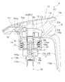
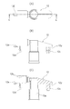
- FIG. 1 is a longitudinal sectional view of a central portion of a trigger type pump dispenser according to an embodiment of the present invention, showing a state where a stopper is inserted between a trigger and an inverted L-shaped handle.
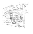
- FIG. 2 is a longitudinal sectional view of the central portion of the trigger type pump dispenser according to the embodiment of the present invention, and shows a state before the trigger is rotated.
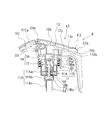
- FIG. 3 is a longitudinal sectional view of the central portion of the trigger type pump dispenser according to the embodiment of the present invention, and shows a state after the trigger is rotated.
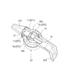
- FIG. 4 is a perspective view showing a state in which the housing, the nozzle base, and the piston structure used in the trigger type pump dispenser according to the embodiment of the present invention are assembled, with the trigger removed.
- FIG. 1 is a longitudinal sectional view of a central portion of a trigger type pump dispenser according to an embodiment of the present invention, showing a state where a stopper is inserted between a trigger and an inverted L-shaped handle.
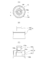
- FIG. 5 shows a nozzle base used in the trigger-type pump dispenser according to the embodiment of the present invention
- FIG. 5 (A) is a plan view of the nozzle base
- FIG. 5 (B) is a front view of the nozzle base
- FIG. 5C is a cross-sectional view of the nozzle base taken along the line aa in FIG. 6 shows a piston used in the trigger type pump dispenser according to the embodiment of the present invention
- FIG. 6 (A) is a plan view of the piston
- FIG. 6 (B) is a front view of the piston
- FIG. 6C is a cross-sectional view of the piston along the bb cross section of
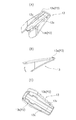
- FIG. 7 shows a piston shaft used in the trigger type pump dispenser according to the embodiment of the present invention
- FIG. 7 (A) is a plan view of the piston shaft
- FIG. 7 (B) is a perspective view of the piston shaft
- 7C is a front view of the piston shaft
- FIG. 7D is a cross-sectional view of the piston shaft taken along the line cc of FIG. 7A.
- FIG. 8 shows a state in which the nozzle base, piston and piston shaft used in the trigger type pump dispenser according to the embodiment of the present invention are assembled
- FIG. 8 (A) is a front view of the assembled state
- FIG. 8B is a cross-sectional view of the assembled state along the dd cross section of FIG.
- FIG. 9 shows a trigger used in the trigger type pump dispenser according to the embodiment of the present invention
- FIG. 9A is a perspective view of the trigger viewed from below
- FIG. 9B is a front view of the trigger
- FIG. 9C is a perspective view of the back surface of the trigger as viewed from below.
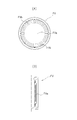
- FIG. 10 shows the outline of the fast valve used for the trigger type pump dispenser which concerns on embodiment of this invention
- FIG. 10 (A) is a top view of a fast valve
- FIG. 10 (B) shows the fast valve. It is sectional drawing.
- FIG. 11 is a cross-sectional view showing another modification of the nozzle base.
- FIG. 12 is a diagram showing a comparison between the above-described embodiment and the nozzle base 12 of FIG. 11 for reference.
- the trigger type pump dispenser A lowers the piston structure 14 by grasping the inverted L-shaped handle portion 11B and pushing down the thumb rest 13a of the trigger 13 with the thumb.
- the liquid is sprayed from the nozzle portion 11C by applying a compressive force.
- FIG. 1 is a longitudinal sectional view of a central portion of a trigger type pump dispenser A according to an embodiment of the present invention, and shows a state where a stopper 21 is inserted between a trigger 13 and an inverted L-shaped handle portion 11B.
- the reason why the stopper 21 is inserted is to prevent the trigger 13 from being pushed down for some reason during storage or transportation of the trigger type pump dispenser A.
- FIG. 2 is a longitudinal sectional view of the central portion of the trigger type pump dispenser A according to the embodiment of the present invention, and shows a state before the trigger is rotated.
- FIG. 3 is a longitudinal sectional view of the central portion of the trigger type pump dispenser A according to the embodiment of the present invention, and shows a state after the trigger is rotated.
- the trigger type pump dispenser A includes a housing 11, a nozzle base 12, a trigger 13, a piston structure 14, a hollow piston 15, and a hollow piston.
- a piston shaft 16, a spring 17, a valve rod 18, a tube 19, and a cap 20 are provided.
- a front cylinder part 11A and a rear inverted L-shaped handle part 11B are integrally formed (see FIG. 4).
- the cylinder portion 11 ⁇ / b> A is not shown because it is inside the cap 20.
- a nozzle base described later is attached to the housing 11.
- the cylinder portion 11A has a large diameter portion 11Aa, a medium diameter portion 11Ab, and a small diameter portion 11Ac.
- the piston 15 slides in the cylinder part.
- a collar 11Aaf is formed on the outer periphery of the large-diameter portion 11Aa, and the collar 11Aaf is pressed by a cap 20 described later and attached to the container.
- the inverted L-shaped handle 11B is located below the thumb rest 13a of the trigger 13 at the rear end of the trigger 13 described later.
- a finger contact portion 11Bs is provided on the side of the inverted L-shaped handle portion 11B facing the cap 20, and this finger contact portion 11Bs is located behind a force point P3 of a thumb rest portion 13a of the trigger 13 described later. Preferably there is.
- the nozzle portion 11 ⁇ / b> C is located in front of the housing 11 (see FIG. 4) and is attached to the nozzle base 12, and the upper surface thereof is flush with the upper surface of the housing 11.
- the nozzle portion 11C has a hollow cylindrical portion 11Ca.
- a second valve SV having a valve body SVa is built in the hollow cylindrical portion 11Ca of the nozzle portion.
- the valve body SVa of the second valve SV is in contact with the bottom (which functions as a valve seat) of the hollow portion 12b (see FIG. 5C) in the lateral direction of the nozzle base 12.
- the nozzle base 12 has a horizontal hollow portion 12b in front thereof and a vertical hollow portion 12a in the center thereof.
- a vertical latching claw 12d and a lateral latching claw 12e are provided on the front side, and a fitting projection 12c is provided on the rear side.
- the trigger 13 is positioned above the housing 11, and the front end thereof is rotatably connected to the mounting hole 11d (see FIG. 4) of the housing 11. That is, the portion of the mounting hole 11d where the front end portion of the trigger 13 is rotatably mounted becomes the rotation fulcrum P1 of the trigger 13.
- a thumb rest 13 a is formed at the rear end of the trigger 13. And the center part of this thumb rest part 13a is the power point P3.
- arc-shaped depressions 13b (two places) and notches 13c (two places) are formed on the back surface of the trigger 13, The arc-shaped depressions 13b (two places) are formed in the substantially middle part of the trigger 13, and the notches 13c (two places) are formed in the vicinity of the rear end part of the trigger 13.
- the support shaft 16c (two pieces) of the bifurcated part 16b of the hollow piston shaft 16 described later contacts the arcuate depressions 13b (two places) of the trigger 13.
- a portion where the support shafts 16c (two pieces) abut, that is, an arcuate depression 13b (two places) serves as an action point P2 of the trigger 13.
- the stopper 21 can be inserted between the trigger 13 and the inverted L-shaped handle portion 11B.
- the stopper 21 has an upper protruding portion 21a and a lower side protruding portion 21b.
- the stopper 21 is slid laterally along the horizontal surface portion 11Bx of the handle portion 11B, and the upper protruding portion 21a is locked to the notch 13c of the trigger 13, and the side protruding portion 21b is locked to the horizontal surface portion of the handle portion 11B.
- 11Bx and the rear step portion 12y of the nozzle base 12 are fitted. In this way, the stopper 21 can be easily attached. Moreover, in order to remove the stopper 21, it can remove by pulling out reversely to the sliding direction mentioned above.
- the piston structure 14 includes a hollow piston 15 and a hollow piston shaft 16.
- the hollow piston 15 is integrally formed so that the large-diameter piston portion 15A, the small-diameter piston portion 15B, and the medium-diameter intermediate portion 15C have the same axis. .
- the lower end of the small-diameter piston portion 15B is connected to the intermediate-diameter intermediate portion 15C by the upper connecting portion 15Ca of the intermediate-diameter intermediate portion 15C, and the vicinity of the lower end of the large-diameter piston portion 15A is
- the lower diameter connecting portion 15Cb of the intermediate diameter intermediate portion 15C is connected to the intermediate diameter intermediate portion 15C.
- a lip portion 15Ba is formed below the inside of the small diameter piston portion 15B, and an outward flange portion 15Bb is formed at the upper end.
- the small-diameter piston portion 15B is slidably inserted into the vertical hollow portion 12a of the nozzle base 12.
- the space in the cylinder portion 11A and the nozzle base 12 is sealed from the outside.
- the small-diameter piston portion 15B moves up and down, but the nozzle base 12 does not move up and down, so the nozzle portion 11C does not move and its position does not change.
- the large-diameter piston portion 15A is slidably inserted into the large-diameter portion 11Aa of the cylinder portion 11A.
- the hollow piston shaft 16 has a bifurcated portion 16b formed at the upper portion of the main body portion 16a. Further, support shafts 16c (two pieces) protrude from the outer surface of the upper portion of the bifurcated portion 16b. As described above, the support shafts 16c (two pieces) are in contact with the arcuate depressions 13b (two places) of the trigger 3. And the part which the spindle 16c (two pieces) contact
- a flange 16f protrudes outside the lower end of the main body portion 16a.
- the hollow piston shaft 16 has a flange 16f at the lower end of the main body 16a, and the lower connecting portion 15Cb of the intermediate diameter intermediate portion 15C described above ((C) in FIG. 6). Contact).
- the spring 17 is a coil spring and urges the piston structure 14 including the hollow piston 15 and the hollow piston shaft 16 upward.
- the upper end portion of the spring 17 is in contact with the back side of the middle connecting portion 15Ca of the middle diameter intermediate portion, and the lower end portion of the spring 17 is in contact with the upper surface of the enlarged portion 18b below the valve rod 18 described later.
- the spring 17 When the push-down of the thumb rest 13a is stopped, the spring 17 extends and urges the piston structure 14 including the hollow piston 15 and the hollow piston shaft 16 upward.
- the support shaft 16c of the hollow piston shaft 16 (fitted in the arcuate depression 13b of the trigger 13) is pushed up, and the trigger 13 is returned to its original position. Return. In this way, the spring 17 functions as a return spring of the trigger 13.
- the valve stem 18 is disposed at the center inside the large diameter portion 11Aa and the medium diameter portion 11Ab of the cylinder portion 11A.
- the valve stem 18 is provided with a valve body 18a having a valve function in cooperation with the lip portion 15Ba of the small-diameter piston portion 15B described above at the distal end portion thereof, and an enlarged portion 18b is provided at a lower base end portion thereof. Yes.
- the enlarged portion 18 b of the valve stem 18 is accommodated in the medium diameter portion 11 Ab of the housing 11.
- the enlarged portion 18b includes a space whose lower end is opened, and a first valve FV is provided in the open portion of the space.
- FIG. 10 An outline of the first valve FV is shown in FIG. 10, and the first valve FV includes a valve body FVa and leaf spring portions FVb (two pieces) as shown in FIG.
- the leaf spring portion FVb supports and biases the valve body FVa.
- the valve body FVa faces a portion that protrudes in an annular shape slightly upward from the middle diameter portion 11Ab of the housing 11 (that is, a portion that functions as a valve seat). The valve opens when the valve body FVa is separated from the annular projecting portion.
- the tube 19 is inserted and attached to the small diameter portion 11Ac of the cylinder portion 11A.
- the first valve FV described above is located above the opening at the upper end of the tube 19.
- the cap 20 is for attaching the housing 11 to the container, and is attached by screwing into the mouth of the container using the collar 11Aaf of the housing 11.
- the aforementioned hollow piston 15 is preferably made of polyethylene, and the other housing 11, nozzle base 12, trigger 13, hollow piston shaft 16, valve rod 18, tube 19, cap 20, and stopper 21 are Are all made of polypropylene. It is not necessarily limited to polyethylene or polypropylene.
- the stopper 21 (see FIG. 1) inserted between the trigger 13 and the inverted L-shaped handle 11B is removed, and the thumb rest 13a of the trigger 13 can be pushed down with the thumb.
- the thumb rest portion 13a of the trigger 13 is pushed down with the thumb.
- the hollow shape is interlocked with the movement of the trigger 13.
- the hollow piston 15 is also moved downward via the piston shaft 16, and the hydraulic pressure inside the large diameter part 11Aa and the medium diameter part 11Ab of the cylinder part 11A is increased.
- the first valve FV closes when the hydraulic pressure inside the medium diameter portion 11Ab increases.
- valve element 18a of the valve rod 18 comes into contact with the lip portion 15Ba of the small-diameter piston portion 15B, and the large-diameter portion 11Aa of the cylinder portion 11A and the nozzle base 12 Communication with the vertical hollow portion 12a (see FIG. 5C) is blocked. Therefore, liquid leakage to the outside is prevented.
- the trigger pump dispenser A has the following effects. Even if the trigger 13 rotates up and down, the position of the nozzle portion 11C does not change, so that it is possible to accurately determine the liquid ejection direction. In addition, since the hollow piston 15 can be moved up and down via the hollow piston shaft 16, the space inside the housing 11 can be reduced.
- the inverted L-shaped handle portion 11B is located under the trigger 13, when the trigger 13 for injecting the liquid is pulled in, it is easy to grip and there is no need to grip the entire trigger type pump dispenser A. Further, it is only necessary to place the thumb on the thumb rest 13a of the trigger 13 and push it down downward with four fingers hooked on the inverted L-shaped handle 11B. Therefore, it can be easily handled even by children with small hands, handicapped persons with weak grip, and finger strength. Further, even when the liquid is attached to the trigger type pump dispenser A itself, it is not soiled because the hand is separated from the trigger type pump dispenser A itself.
- the trigger 13 located above the inverted L-shaped handle portion 11B is pushed down to eject the liquid in the cylinder portion 11A from the nozzle portion 11C. Since the finger contact portion 11Bs of the inverted L-shaped handle portion 11B is behind the power point P3 of the thumb rest portion 13a of the trigger 13, the grip is good and the holding property is high. In addition, finger power is efficiently transmitted and the operability is excellent.
- the stopper 21 can be easily inserted, attached, and removed by sliding along the horizontal surface portion 11Bx of the handle portion 11B.
- FIG. 11 is a cross-sectional view showing a modified example of the nozzle base 12.
- the nozzle portion 11C is formed integrally with the nozzle base 12.
- the vertical hollow portion 12a is different from the nozzle base 12 unlike the nozzle base 12 of FIG. 1, and the second valve SV is mounted on the vertical hollow portion 12a.
- An upper lip portion 12a1 is formed in the hollow portion 12a in the vertical direction, and this and the valve body of the second valve SV cooperate to exert a valve opening / closing function.
- FIG. 12 is a view showing a comparison between the above-described embodiment (FIGS. 1 to 10) and the nozzle base 12 of FIG. 11 for reference.
- (A) shows the nozzle base 12 of the embodiment described above, and
- (B) shows the nozzle base 12 of FIG. In any case, the nozzle base 12 does not move up and down, and the nozzle portion 11C does not move.
- the present invention can be applied, for example, to the general industry for painting or medical instruments as long as it uses the liquid jet principle of the present invention.
- Piston structure 15 Hollow piston 15A ... Large diameter piston part 15B ... Small diameter piston part 15Ba ... Lip part 15Bb of small diameter piston part ... ⁇ part 15C ... middle diameter intermediate part 15Ca ... middle diameter middle part upper coupling part 15Cb ... middle diameter middle part lower coupling part 16 ... hollow piston Shaft 16a ... Body 16b ... Fork 16c ... Spindle 16f ... Rib 17 ... Spring 18 ... Valve 18a ... Valve 18b ... Enlarged part 19 ... Tube 20 ... Cap 21 ... Stopper 21a ... Upper protrusion 21b ... Side Projection part SV ... Second valve SVa ... Second valve body FV ... First valve FVa ... First valve body FVb ... First valve leaf spring part P1 ... Support point P2 ... Action point P3 ... Power point A ... Trigger type pump dispenser
Landscapes
- Engineering & Computer Science (AREA)
- Mechanical Engineering (AREA)
- General Engineering & Computer Science (AREA)
- Containers And Packaging Bodies Having A Special Means To Remove Contents (AREA)
- Closures For Containers (AREA)
- Reciprocating Pumps (AREA)
Abstract
ノズル部の位置が上下に移動せず液の噴射方向を的確に定めることができ、手が汚れずにグリップ性もよく、噴射の際、指力がトリガー部に効率よく伝わり操作性に優れたトリガー式ポンプディスペンサを提供する。前方のシリンダ部(11A)と後方の逆L字状の取っ手部(11B)とが一体に形成されたハウジング(11)と、該ハウジング(11)に取り付けられ、前方のノズル部(11C)が装着されたノズルベース(12)と、中空状のピストン(15)と中空状のピストンシャフト(16)とから構成され前記シリンダ部内を摺動するピストン構造体と、ピストン構造体(14)を上方に付勢するスプリング(17)と、ハウジング(11)の上方に位置し、前方の先端がハウジング(11)に回動可能に装着され、その中間部に中空状のピストンシャフト(16)の先端が当接されるトリガー(13)と、シリンダ部(11A)の中心部に配置される弁棒(18)と、を備える。
Description
本発明は、容器に取り付けて中に収容された液を効率よく噴射させるためのトリガー式ポンプディスペンサに関する。
従来、容器に取り付けて内部の液を吐出あるいは噴射させる器具としてトリガー式ポンプディスペンサが広く使用されている。
トリガー式ポンプディスペンサは、通常、ピストン及びシリンダを備えており、ピストンを移動させることでシリンダ内に圧を加え液が噴射されるものである。
このトリガー式ポンプディスペンサはピストンの動かし方によりタイプが分かれている。
その一つとして、例えば、4本の指でトリガーを引き込む形式のトリガー式ポンプディスペンサがある(特許文献1、特許文献2参照)。
トリガー式ポンプディスペンサは、通常、ピストン及びシリンダを備えており、ピストンを移動させることでシリンダ内に圧を加え液が噴射されるものである。
このトリガー式ポンプディスペンサはピストンの動かし方によりタイプが分かれている。
その一つとして、例えば、4本の指でトリガーを引き込む形式のトリガー式ポンプディスペンサがある(特許文献1、特許文献2参照)。
この特許文献1及び特許文献2に開示されているこれらのトリガー式ポンプディスペンサは、その前方にトリガーが設けられており、前方のトリガーを手で握り込んで後方に移動させると、トリガーの動きに連動してピストンを押し下げてシリンダ内の液圧が高まる。
その結果、ノズル部から液が勢いよく噴射されるものである。
その結果、ノズル部から液が勢いよく噴射されるものである。
また、従来、トリガーを本体の上方に配置して、トリガーの後端を押し込んで、トリガーの動きに連動してピストンを押し下げてシリンダ内の液圧が高まるタイプのトリガー式ポンプディスペンサが提案されている(特許文献3参照)。
この特許文献3に記載のトリガー式ポンプディスペンサは、更にいうなら、以下のような構造のものである。
すなわち、この特許文献3に記載のトリガー式ポンプディスペンサの構造は、容器に取り付け可能なトリガー式ポンプディスペンサであって、シリンダ部と、シリンダ部内に摺動自在なピストン構造体と、シリンダ部に装着されたハウジング部と、ハウジング部に一体形成された取っ手部と、ハウジング部に装着され、クランク部を介してピストン構造体に連結されるトリガー部と、シリンダ部を容器本体に取り付けるためのキャップとを備えている。
そしてピストン構造体は屈曲自在な長尺ノズル部とピストン部とが一体化されており、トリガー部を押し下げて取っ手部に近づけることにより、クランク部を介してピストン部を押し下げシリンダ部内に圧を加えて長尺ノズル部を通して液を吐出させる。
しかしながら、上述した特許文献1及び特許文献2に記載のこれらのトリガー式ポンプディスペンサにおいては、トリガーを引き込む場合、トリガー式ポンプディスペンサの周囲全体を手の平で握り、指を使ってトリガーを横方向に引き込まなければならない。
そのため、手の小さい子供、握力、指力の落ちた身障者等が扱う際には、トリガーを握る状態が浅くなり、力を入れ難くなる。
また、4本の指を使って全体を握るため、トリガー式ポンプディスペンサ本体の周囲に液等が付着している場合、それが手に付着し汚れる欠点がある。
特にノズルの真下に位置する指は汚れ易い。
そのため、手の小さい子供、握力、指力の落ちた身障者等が扱う際には、トリガーを握る状態が浅くなり、力を入れ難くなる。
また、4本の指を使って全体を握るため、トリガー式ポンプディスペンサ本体の周囲に液等が付着している場合、それが手に付着し汚れる欠点がある。
特にノズルの真下に位置する指は汚れ易い。
また、特許文献3に記載のトリガー式ポンプディスペンサは、特許文献1及び特許文献2についての上記のような欠点を解決することができる。
しかしながら、次のような問題点がある。
すなわち、トリガー部がクランク部を介してピストン構造体に連結されること、及びトリガー部が押し込まれると長尺ノズル部が屈曲すること、により、ハウジング部に余分な空間が必要になるという問題がある。
すなわち、トリガー部がクランク部を介してピストン構造体に連結されること、及びトリガー部が押し込まれると長尺ノズル部が屈曲すること、により、ハウジング部に余分な空間が必要になるという問題がある。
さらに、特許文献3に記載のトリガー式ポンプディスペンサは、トリガー部を押し下げて取っ手部に近づけることにより液を吐出させるものであるから、操作性に優れているといえる。
今後は、グリップ性の観点から更に使い良いものが望まれている。
今後は、グリップ性の観点から更に使い良いものが望まれている。
そこで、本出願人は、既に、特願2013-185763号(特開2015-51398号)として、グリップ性がよく噴射の際、指力がトリガー部に効率よく伝わり操作に優れたトリガー式ポンプディスペンサを提案した。
ところで、このトリガー式ポンプディスペンサは、概略、取っ手部を握った状態で、該取っ手部の上方にあるトリガー部を押し下げて、シリンダ部内の液体をノズル部から噴射させるトリガー式ポンプディスペンサにおいて、取っ手部の指当接部が、トリガー部の力点より後方にあることを特徴とするものである。
しかし、取っ手部とトリガー部とを握って、トリガー部を下方に押し下げると、それに伴ってピストン部も下方に移動する。
この場合、ピストン部が下方に移動するとノズル部も下方に移動する。
したがって、液を噴射させる際にノズル部の位置が上下に移動するという問題が残る。
しかし、取っ手部とトリガー部とを握って、トリガー部を下方に押し下げると、それに伴ってピストン部も下方に移動する。
この場合、ピストン部が下方に移動するとノズル部も下方に移動する。
したがって、液を噴射させる際にノズル部の位置が上下に移動するという問題が残る。
本発明は、かかる背景技術をもとになされたもので、ノズル部の位置が上下に移動せず液の噴射方向を的確に定めることができ、手が汚れずにグリップ性もよく、噴射の際、指力がトリガー部に効率よく伝わり操作性に優れたトリガー式ポンプディスペンサを提供することを目的とする。
本発明者らは、上記課題を解決するため鋭意検討したところ、トリガーとピストンとの間に中空状のピストンシャフトを介在させることにより、上記課題を解決し得ることを見出し、本発明を完成するに到った。
本発明は、(1)、容器に取り付け可能なトリガー式ポンプディスペンサであって、前方のシリンダ部と後方の逆L字状の取っ手部とが一体に形成されたハウジングと、該ハウジングに取り付けられ、前方のノズル部が装着されたノズルベースと、中空状のピストンと中空状のピストンシャフトとから構成され前記シリンダ部内を摺動するピストン構造体と、前記中空状のピストンと前記中空状のピストンシャフトとを上方に付勢するスプリングと、前記ハウジングの上方に位置し、前方の先端が前記ハウジングに回動可能に装着され、その中間部に前記ピストンシャフトの先端が当接されるトリガーと、前記シリンダ部の内部の中心部に配置されている弁棒と、を備え、前記中空状のピストンは、大径ピストン部と小径ピストン部と中径中間部とが同じ軸心を持つように一体的に形成され、前記小径ピストン部は内部にリップ部を有し、前記弁棒は、その先端部に、前記リップ部と協働する弁機能を有する弁体を有し、その基端部に、拡大部を有し、前記逆L字状の取っ手部の指当接部が、前記トリガーの親指当て部の力点より後方にあるトリガー式ポンプディスペンサに存する。
本発明は、(2)、前記中空状のピストンシャフトは、その上部が二股部に形成され、前記二股部の先端部は前記トリガーに当接され、その下部は前記中空状のピストンに組み込まれている上記(1)に記載のトリガー式ポンプディスペンサに存する。
本発明は、(3)、前記二股部の先端部の外側面には、それぞれ支軸が突出している上記(2)に記載のトリガー式ポンプディスペンサに存する。
本発明は、(4)、前記ノズルベース部に形成された縦方向の中空部内をピストン構造体の小径ピストン部が摺動自在となっており、ピストン構造体の動きがノズルベースに伝わらないようになっている上記(1)に記載のトリガー式ポンプディスペンサに存する。
本発明は、(5)、前記トリガーと前記逆L字形の取っ手部との間にストッパを挿入した上記(1)~(4)のいずれか一つに記載のトリガー式ポンプディスペンサに存する。
なお、本発明の目的に添ったものであれば、上記の各発明の構成を適宜組み合わせた構成も採用可能である。
本発明に係るトリガー式ポンプディスペンサによれば、次のような効果を有する。
トリガーが上下に回動しても、ノズル部の位置は変化しないので、液の噴射方向を的に向けて的確に定めることができる。
トリガーが上下に回動しても、ノズル部の位置は変化しないので、液の噴射方向を的に向けて的確に定めることができる。
また、中空状のピストンシャフトを介して中空状のピストンの上下の移動を行うことができるので、ハウジングの内部の空間を少なくすることができる。
また、逆L字形の取っ手部がトリガーの下に位置しているので、液を噴射するためのトリガーを引き込む場合、握りよく、トリガー式ポンプディスペンサ全体を握る必要はない。
また、逆L字形の取っ手部に4本の指を引っ掛けた状態で親指をトリガーの上に添えて、単に下方に押し下げるだけでよい。
また、逆L字形の取っ手部がトリガーの下に位置しているので、液を噴射するためのトリガーを引き込む場合、握りよく、トリガー式ポンプディスペンサ全体を握る必要はない。
また、逆L字形の取っ手部に4本の指を引っ掛けた状態で親指をトリガーの上に添えて、単に下方に押し下げるだけでよい。
そのため、手の小さい子供、握力、指力の落ちた身障者等でも簡単に扱うことができる。
さらに、トリガー式ポンプディスペンサ自体に液が付着している場合にも、手がトリガー式ポンプディスペンサ自体より離れているため汚れない。
さらに、トリガー式ポンプディスペンサ自体に液が付着している場合にも、手がトリガー式ポンプディスペンサ自体より離れているため汚れない。
また、逆L字形の取っ手部を握った状態で、逆L字形の取っ手部の上方にあるトリガーを押し下げて、シリンダ部内の液体をノズル部から噴射するトリガー式ポンプディスペンサであり、逆L字状の取っ手部の指当接部が、トリガーの親指当て部の力点より後方にあるので、握りよく保持性が高く(すなわちグリップ性が良く)、力が効率良く伝達され操作性にも優れている。
また前記ノズルベース部に形成された縦方向の中空部内をピストン構造体の小径ピストン部が摺動自在となっており、ピストン構造体の動きがノズルベースに伝わらないようになっているので、噴射方向を的に向けて的確に定めることができる。
また、トリガーと逆L字形の取っ手部の間にストッパを挿入することで、トリガー式ポンプディスペンサを保管中または輸送中に何らかの事情でトリガーが押し下げられるのを防止することができる。
また前記ノズルベース部に形成された縦方向の中空部内をピストン構造体の小径ピストン部が摺動自在となっており、ピストン構造体の動きがノズルベースに伝わらないようになっているので、噴射方向を的に向けて的確に定めることができる。
また、トリガーと逆L字形の取っ手部の間にストッパを挿入することで、トリガー式ポンプディスペンサを保管中または輸送中に何らかの事情でトリガーが押し下げられるのを防止することができる。
本発明の実施形態に係るトリガー式ポンプディスペンサAについて、以下に図面を参照して説明する。
本発明の実施形態に係るトリガー式ポンプディスペンサAは、逆L字形の取っ手部11Bを握って、トリガー13の親指当て部13aを親指を使って下に押し下げることで、ピストン構造体14を下降させて、液に圧縮力を与えてノズル部11Cから噴射させる構造である。
図1は、本発明の実施形態に係るトリガー式ポンプディスペンサAの中心部の縦断面図で、トリガー13と逆L字形の取っ手部11Bの間にストッパ21を挿入した状態を示す。
ストッパ21を挿入するのは、トリガー式ポンプディスペンサAを保管中または輸送中に何らかの事情でトリガー13が押し下げられるのを防止するためである。
ストッパ21を挿入するのは、トリガー式ポンプディスペンサAを保管中または輸送中に何らかの事情でトリガー13が押し下げられるのを防止するためである。
図2は、本発明の実施形態に係るトリガー式ポンプディスペンサAの中心部の縦断面図で、トリガーの回動前の状態を示す。
図3は、本発明の実施形態に係るトリガー式ポンプディスペンサAの中心部の縦断面図で、トリガーの回動後の状態を示す。
図2に示すように、本発明の実施形態に係るトリガー式ポンプディスペンサAは、ハウジング11と、ノズルベース12と、トリガー13と、ピストン構造体14と、中空状のピストン15と、中空状のピストンシャフト16と、スプリング17と、弁棒18と、チューブ19と、キャップ20と、を備えている。
ハウジング11は、前方のシリンダ部11Aと後方の逆L字状の取っ手部11Bとが一体に形成されている(図4参照)。
なお、図4においては、シリンダ部11Aはキャップ20の内側にあるため、図示されていない。
またハウジング11には後述するノズルベースが取り付けられている。
なお、図4においては、シリンダ部11Aはキャップ20の内側にあるため、図示されていない。
またハウジング11には後述するノズルベースが取り付けられている。
またシリンダ部11Aは、大径部11Aaと中径部11Abと小径部11Acとを有している。
なお、ピストン15は、このシリンダ部内を摺動する。
大径部11Aaの外周には、つば11Aafが形成されており、このつば11Aafを後述するキャップ20で押さえ込んで容器に取り付ける。
なお、ピストン15は、このシリンダ部内を摺動する。
大径部11Aaの外周には、つば11Aafが形成されており、このつば11Aafを後述するキャップ20で押さえ込んで容器に取り付ける。
逆L字形の取っ手部11Bは、後述するトリガー13の後端にあるトリガー13の親指当て部13aの下方に位置している。
そして、逆L字形の取っ手部11Bのキャップ20に対向する側には、指当接部11Bsがあり、この指当接部11Bsは、後述するトリガー13の親指当て部13aの力点P3より後方にあることが好ましい。
そして、逆L字形の取っ手部11Bのキャップ20に対向する側には、指当接部11Bsがあり、この指当接部11Bsは、後述するトリガー13の親指当て部13aの力点P3より後方にあることが好ましい。
ノズル部11Cは、ハウジング11の前方に位置し(図4参照)、ノズルベース12に装着されており、その上面はハウジング11の上面と面一となっている。
ノズル部11Cの内部には中空円筒部11Caを有している。
このノズル部の中空円筒部11Ca内には、弁体SVaを有するセカンドバルブSVが内蔵されている。
そして、ノズルベース12の横方向の中空部12b(図5(C)参照)の底部(弁座の機能をする)に、セカンドバルブSVの弁体SVaが当接している。
ノズル部11Cの内部には中空円筒部11Caを有している。
このノズル部の中空円筒部11Ca内には、弁体SVaを有するセカンドバルブSVが内蔵されている。
そして、ノズルベース12の横方向の中空部12b(図5(C)参照)の底部(弁座の機能をする)に、セカンドバルブSVの弁体SVaが当接している。
図5(A)~(C)に示すように、ノズルベース12は、その前方に横方向の中空部12bを有し、その中央に縦方向の中空部12aを有している。
また、その前方に縦方向の掛け止め爪12dと横方向の掛け止め爪12eを備え、後方には嵌合突起12cを備えている。
また、その前方に縦方向の掛け止め爪12dと横方向の掛け止め爪12eを備え、後方には嵌合突起12cを備えている。
またトリガー13は、ハウジング11の上方に位置し、その前方の端部がハウジング11の取り付け孔11d(図4参照)に回動可能に連結されている。
すなわち、トリガー13の前方の端部が回動可能に取り付けられる前述の取り付け孔11dの部分がトリガー13の回動支点P1となる。
すなわち、トリガー13の前方の端部が回動可能に取り付けられる前述の取り付け孔11dの部分がトリガー13の回動支点P1となる。
また、図2、図9(A)及び図9(B)に示すように、トリガー13の後方の先端に、親指当て部13aが形成されている。
そして、この親指当て部13aの中心部が力点P3になっている。
また、図9(A)及び図9(C)に示すように、トリガー13の裏面に、円弧状のくぼみ13b(2箇所)と、切欠き13c(2箇所)とが形成されており、円弧状のくぼみ13b(2箇所)はトリガー13の略中間部に形成され、切欠き13c(2箇所)はトリガー13の後端部の近傍に形成されている。
そして、後述する中空状のピストンシャフト16の二股部16bの支軸16c(2個)がトリガー13の円弧状のくぼみ13b(2箇所)に当接する。
支軸16c(2個)が当接する部分、すなわち円弧状のくぼみ13b(2箇所)がトリガー13の作用点P2となっている。
そして、この親指当て部13aの中心部が力点P3になっている。
また、図9(A)及び図9(C)に示すように、トリガー13の裏面に、円弧状のくぼみ13b(2箇所)と、切欠き13c(2箇所)とが形成されており、円弧状のくぼみ13b(2箇所)はトリガー13の略中間部に形成され、切欠き13c(2箇所)はトリガー13の後端部の近傍に形成されている。
そして、後述する中空状のピストンシャフト16の二股部16bの支軸16c(2個)がトリガー13の円弧状のくぼみ13b(2箇所)に当接する。
支軸16c(2個)が当接する部分、すなわち円弧状のくぼみ13b(2箇所)がトリガー13の作用点P2となっている。
前述したように、ストッパ21は、トリガー13と逆L字形の取っ手部11Bの間に挿入することができる。
そして、ストッパ21は、上部の突出部21aと下部側部の突出部21bを有している。
ストッパ21を取っ手部11Bの水平面部11Bxに沿って横方向にスライドさせ、上部の突出部21aをトリガー13の切欠き13cに係止させるとともに、側部の突出部21bを取っ手部11Bの水平面部11Bxとノズルベース12の後方段部12yとの間に嵌め込む。
このようにして、ストッパ21を簡単に取り付けることができる。
また、ストッパ21を取り外すには、上述したスライド方向と逆に引き出すことにより取り外すことができる。
そして、ストッパ21は、上部の突出部21aと下部側部の突出部21bを有している。
ストッパ21を取っ手部11Bの水平面部11Bxに沿って横方向にスライドさせ、上部の突出部21aをトリガー13の切欠き13cに係止させるとともに、側部の突出部21bを取っ手部11Bの水平面部11Bxとノズルベース12の後方段部12yとの間に嵌め込む。
このようにして、ストッパ21を簡単に取り付けることができる。
また、ストッパ21を取り外すには、上述したスライド方向と逆に引き出すことにより取り外すことができる。
図8(A)、図8(B)に示すように、ピストン構造体14は、中空状のピストン15と中空状のピストンシャフト16とから構成されている。
まず中空状のピストン15は、図6に示すように、大径ピストン部15Aと、小径ピストン部15Bと、中径中間部15Cと、が同じ軸心を持つように一体的に形成されている。
すなわち、図6(C)に示すように、小径ピストン部15Bの下端は、中径中間部15Cの上部連結部15Caで中径中間部15Cに連結され、大径ピストン部15Aの下端の近傍は中径中間部15Cの下部連結部15Cbで中径中間部15Cに連結されている。
そして、小径ピストン部15Bの内部の下方にはリップ部15Baが形成され、上端には外向きの鍔部15Bbが形成されている。
小径ピストン部15Bは、ノズルベース12の縦方向の中空部12a内に摺動自在に挿入される。
この状態ではシリンダ部11Aとノズルベース12内の空間が外部と封止される。
後で述べるように、トリガー13を操作して液を噴射させる場合、この小径ピストン部15Bは上下移動するがノズルベース12は上下移動しないので、ノズル部11Cは、動かず、その位置は変化しない。
また、大径ピストン部15Aは、シリンダ部11Aの大径部11Aa内に摺動自在に挿入される。
そして、小径ピストン部15Bの内部の下方にはリップ部15Baが形成され、上端には外向きの鍔部15Bbが形成されている。
小径ピストン部15Bは、ノズルベース12の縦方向の中空部12a内に摺動自在に挿入される。
この状態ではシリンダ部11Aとノズルベース12内の空間が外部と封止される。
後で述べるように、トリガー13を操作して液を噴射させる場合、この小径ピストン部15Bは上下移動するがノズルベース12は上下移動しないので、ノズル部11Cは、動かず、その位置は変化しない。
また、大径ピストン部15Aは、シリンダ部11Aの大径部11Aa内に摺動自在に挿入される。
図7(A)~(D)に示すように、中空状のピストンシャフト16は、本体部16aの上部は、二股部16bが形成されている。
また、二股部16bの上部の外側面には、支軸16c(2個)が突出している。
前述したように、支軸16c(2個)が、トリガー3の円弧状のくぼみ13b(2箇所)に当接している。
そして、支軸16c(2個)が当接する部分、すなわち円弧状のくぼみ13b(2箇所)がトリガー13の作用点P2となっている。
また、本体部16aの下端の外側には、つば16fが突出している。
また、二股部16bの上部の外側面には、支軸16c(2個)が突出している。
前述したように、支軸16c(2個)が、トリガー3の円弧状のくぼみ13b(2箇所)に当接している。
そして、支軸16c(2個)が当接する部分、すなわち円弧状のくぼみ13b(2箇所)がトリガー13の作用点P2となっている。
また、本体部16aの下端の外側には、つば16fが突出している。
そして、図8(B)に示すように、中空状のピストンシャフト16は、本体部16aの下端部のつば16fが、前述した中径中間部15Cの下部連結部15Cb(図6の(C)参照)に当接している。
スプリング17は、コイルスプリングであり、中空状のピストン15と中空状のピストンシャフト16とからなるピストン構造体14を上方に付勢する。
スプリング17の上端部は、中径中間部の上部連結部15Caの裏側に当接しており、スプリング17の下端部は、後述する弁棒18の下部の拡大部18bの上面に当接している。
そして、トリガー13の親指当て部13aを親指で押し下げて、トリガー13を回動させると、中空状のピストン15と中空状のピストンシャフト16とからなるピストン構造体14が下方に移動し、スプリング17は圧縮される。
スプリング17の上端部は、中径中間部の上部連結部15Caの裏側に当接しており、スプリング17の下端部は、後述する弁棒18の下部の拡大部18bの上面に当接している。
そして、トリガー13の親指当て部13aを親指で押し下げて、トリガー13を回動させると、中空状のピストン15と中空状のピストンシャフト16とからなるピストン構造体14が下方に移動し、スプリング17は圧縮される。
また、親指当て部13aの押し下げを中止すると、スプリング17は伸張して中空状のピストン15と中空状のピストンシャフト16とからなるピストン構造体14を上方に付勢する。
そして、ピストン構造体14が上方に付勢されると、中空状のピストンシャフト16の支軸16c(トリガー13の円弧状のくぼみ13bに嵌っている)が押し上げられ、トリガー13が元の位置に復帰する。
このようにスプリング17がトリガー13の復帰ばねの機能を果たすこととなる。
そして、ピストン構造体14が上方に付勢されると、中空状のピストンシャフト16の支軸16c(トリガー13の円弧状のくぼみ13bに嵌っている)が押し上げられ、トリガー13が元の位置に復帰する。
このようにスプリング17がトリガー13の復帰ばねの機能を果たすこととなる。
弁棒18は、シリンダ部11Aの大径部11Aa及び中径部11Abの内部の中心部に配置されている。
弁棒18は、その先端部には、先述した小径ピストン部15Bのリップ部15Baと協働する弁機能を有する弁体18aを備え、その下方の基端部には、拡大部18bを備えている。
そして、弁棒18のこの拡大部18bは、ハウジング11の中径部11Ab内に収容されている。
また、この拡大部18bは、下端が開放された空所を備え、この空所の開放部にはファーストバルブFVを備えている。
弁棒18は、その先端部には、先述した小径ピストン部15Bのリップ部15Baと協働する弁機能を有する弁体18aを備え、その下方の基端部には、拡大部18bを備えている。
そして、弁棒18のこの拡大部18bは、ハウジング11の中径部11Ab内に収容されている。
また、この拡大部18bは、下端が開放された空所を備え、この空所の開放部にはファーストバルブFVを備えている。
ファーストバルブFVの概略は、図10に示し、ファーストバルブFVは、図10(A)に示すように、弁体FVaと板ばね部FVb(2個)から構成されている。
そして、板ばね部FVbは、弁体FVaを支持し、付勢する。
また、弁体FVaはハウジング11の中径部11Abからわずかに上方に環状に突出する部分(すなわち、弁座の働きをする部分)に対向している。
弁体FVaがこの環状に突出する部分から離れることにより弁が開くことになる。
そして、板ばね部FVbは、弁体FVaを支持し、付勢する。
また、弁体FVaはハウジング11の中径部11Abからわずかに上方に環状に突出する部分(すなわち、弁座の働きをする部分)に対向している。
弁体FVaがこの環状に突出する部分から離れることにより弁が開くことになる。
図2、図3に示すように、チューブ19は、シリンダ部11Aの小径部11Acに挿入されて取り付けられている。
そして、チューブ19の上端部の開口の上方には前述したファーストバルブFVが位置している。
そして、チューブ19の上端部の開口の上方には前述したファーストバルブFVが位置している。
図2、図3に示すように、キャップ20は、ハウジング11を容器に取り付けるためのものであり、ハウジング11のつば11Aafを利用して容器の口部に螺合して取り付ける。
なお、好ましくは前述の中空状のピストン15は、ポリエチレン製であり、その他のハウジング11、ノズルベース12、トリガー13、中空状のピストンシャフト16、弁棒18、チューブ19、キャップ20、ストッパ21は、すべて、ポリプロピレン製である。
尚、必ずしもポリエチレン製やポリプロピレン製に限定されるものではない。
尚、必ずしもポリエチレン製やポリプロピレン製に限定されるものではない。
次に、本発明の実施形態に係るトリガー式ポンプディスペンサAの作動について説明する。
まず、トリガー13と逆L字形の取っ手部11Bの間に挿入しているストッパ21(図1参照)を取り外し、トリガー13の親指当て部13aを親指で押し下げることができる状態にする。
まず、トリガー13と逆L字形の取っ手部11Bの間に挿入しているストッパ21(図1参照)を取り外し、トリガー13の親指当て部13aを親指で押し下げることができる状態にする。
次に、図3に示すように、逆L字形の取っ手部11Bとトリガー13とを握って、トリガー13の親指当て部13aを親指で押し下げると、ノズルベース12の上面に当接するまでトリガー13は支点P1を中心に回動する。
逆L字形の取っ手部11Bとトリガー13とを握って、トリガー13の親指当て部13aを親指で押し下げ、トリガー13は支点P1を中心に回動すると、トリガー13の動きに連動して中空状のピストンシャフト16を介して中空状のピストン15も下方に移動し、シリンダ部11Aの大径部11Aa及び中径部11Abの内部の液圧が高まる。
なお、中径部11Abの内部の液圧が高まると、ファーストバルブFVは閉じる。
なお、中径部11Abの内部の液圧が高まると、ファーストバルブFVは閉じる。
スプリング17の復帰力に抗して、中空状のピストン15と中空状のピストンシャフト16とからなるピストン構造体14が下方に移動すると、弁棒18の弁体18aが小径ピストン部15Bのリップ部15Baとの接触が外れ、シリンダ部11Aの大径部11Aaの内側がノズルベース12の縦方向の中空部12a(図5(C)参照)に連通する。
よって、縦方向の中空部12a内の高まった液圧は、弁体SVaに作用してセカンドバルブ弁体SVが開く。
そのため、液は、ノズル部11Cから噴射される。
この場合、トリガー13が支点P1を中心にする回動によって、中空状のピストン15が下方に移動しても、ノズル部11Cは動かず定位置にある。
よって、縦方向の中空部12a内の高まった液圧は、弁体SVaに作用してセカンドバルブ弁体SVが開く。
そのため、液は、ノズル部11Cから噴射される。
この場合、トリガー13が支点P1を中心にする回動によって、中空状のピストン15が下方に移動しても、ノズル部11Cは動かず定位置にある。
また、図2に示すように、親指によるトリガー13からの押圧力を開放すると、スプリング17の復帰力により、中空状のピストンシャフト16及び中空状のピストン15からなるピストン構造体14が上昇して元の位置に戻る。
なお、トリガー13は、中空状のピストンシャフト16の支軸16c(2個)がトリガー13の円弧状のくぼみ13b(2箇所)に当接しているので、スプリング17の復帰力により、トリガー13も元の位置に回動して戻る。
中空状のピストン15が上昇するとシリンダ部内は負圧になるので、セカンドバルブSVは閉じて、ファーストバルブFVが開き、容器本体内の液がチューブ19によって吸い上げられる。
なお、トリガー13は、中空状のピストンシャフト16の支軸16c(2個)がトリガー13の円弧状のくぼみ13b(2箇所)に当接しているので、スプリング17の復帰力により、トリガー13も元の位置に回動して戻る。
中空状のピストン15が上昇するとシリンダ部内は負圧になるので、セカンドバルブSVは閉じて、ファーストバルブFVが開き、容器本体内の液がチューブ19によって吸い上げられる。
ここで中空状のピストン15が上昇して元の位置に戻ると、弁棒18の弁体18aが小径ピストン部15Bのリップ部15Baと接触し、シリンダ部11Aの大径部11Aaとノズルベース12の縦方向の中空部12a(図5(C)参照)との連通が遮断される。
そのため、外部への液漏れが防止されることとなる。
そのため、外部への液漏れが防止されることとなる。
本発明の実施形態に係るトリガー式ポンプディスペンサAによれば、次のような効果を有する。
トリガー13が上下に回動しても、ノズル部11Cの位置は変化しないので、液の噴射方向を的に向けて的確に定めることができる。
また、中空状のピストンシャフト16を介して中空状のピストン15の上下の移動を行うことができるので、ハウジング11の内部の空間を少なくすることができる。
トリガー13が上下に回動しても、ノズル部11Cの位置は変化しないので、液の噴射方向を的に向けて的確に定めることができる。
また、中空状のピストンシャフト16を介して中空状のピストン15の上下の移動を行うことができるので、ハウジング11の内部の空間を少なくすることができる。
また、逆L字形の取っ手部11Bがトリガー13の下に位置しているので、液を噴射するためのトリガー13を引き込む場合、握り易く、トリガー式ポンプディスペンサA全体を握る必要はない。
また、逆L字形の取っ手部11Bに4本の指を引っ掛けた状態で親指をトリガー13の親指当て部13aの上に添えて、単に下方に押し下げるだけでよい。
そのため、手の小さい子供、握力、指力の落ちた身障者等でも簡単に扱うことができる。
さらに、トリガー式ポンプディスペンサA自体に液が付着している場合にも、手がトリガー式ポンプディスペンサA自体より離れているため汚れない。
また、逆L字形の取っ手部11Bに4本の指を引っ掛けた状態で親指をトリガー13の親指当て部13aの上に添えて、単に下方に押し下げるだけでよい。
そのため、手の小さい子供、握力、指力の落ちた身障者等でも簡単に扱うことができる。
さらに、トリガー式ポンプディスペンサA自体に液が付着している場合にも、手がトリガー式ポンプディスペンサA自体より離れているため汚れない。
また、逆L字形の取っ手部11Bを握った状態で、逆L字形の取っ手部11Bの上方にあるトリガー13を押し下げて、シリンダ部11A内の液体をノズル部11Cから噴射するトリガー式ポンプディスペンサAであり、逆L字状の取っ手部11Bの指当接部11Bsが、トリガー13の親指当て部13aの力点P3より後方にあるので、握りよく保持性が高い。
また、指力が効率よく伝達されて操作性に優れる。
また、指力が効率よく伝達されて操作性に優れる。
また、トリガー13と逆L字形の取っ手部11Bの間にストッパ21を挿入することで、トリガー式ポンプディスペンサAを保管中または輸送中に何らかの事情でトリガー13が押し下げられるのを防止することができる。
そして、前述したように、ストッパ21の挿入すなわち取り付け、及び取り外しは、取っ手部11Bの水平面部11Bxに沿ってスライドさせることで、簡単に行うことができる。
以上、本発明の好適な実施形態について説明したが、本発明は上記の実施形態に限定されるものではない。
そして、前述したように、ストッパ21の挿入すなわち取り付け、及び取り外しは、取っ手部11Bの水平面部11Bxに沿ってスライドさせることで、簡単に行うことができる。
以上、本発明の好適な実施形態について説明したが、本発明は上記の実施形態に限定されるものではない。
例えば、図11は、ノズルベース12の変形例を示す断面図である。
この場合、上述した図1のノズル部11Cと異なって、このノズル部11Cはノズルベース12と一体に成形されている。
また縦方向の中空部12aは、図1のノズルベース12とは異なって、ノズルベース12とは別部品となっており、またセカンドバルブSVは、この縦方向の中空部12aに装着されている。
そして、縦方向の中空部12aには、上リップ部12a1が形成され、これとセカンドバルブSVの弁体とが協働して弁の開閉機能を発揮する。
この場合、上述した図1のノズル部11Cと異なって、このノズル部11Cはノズルベース12と一体に成形されている。
また縦方向の中空部12aは、図1のノズルベース12とは異なって、ノズルベース12とは別部品となっており、またセカンドバルブSVは、この縦方向の中空部12aに装着されている。
そして、縦方向の中空部12aには、上リップ部12a1が形成され、これとセカンドバルブSVの弁体とが協働して弁の開閉機能を発揮する。
また、図12は、上述した実施の形態(図1~図10)と図11のノズルベース12の比較を参考までに示した図である。
(A)は上述した実施の形態のノズルベース12を示し、(B)は図11のノズルベース12を示す。
いずれにしてもノズルベース12は、上下移動しなく、ノズル部11Cは動かない構造となっている。
(A)は上述した実施の形態のノズルベース12を示し、(B)は図11のノズルベース12を示す。
いずれにしてもノズルベース12は、上下移動しなく、ノズル部11Cは動かない構造となっている。
本発明は、例えば、当該発明の液体噴射原理を使用するものであれば、塗装用としての工業全般、あるいは医療用器具等の分野に適用が可能である。
11…ハウジング
11d…取り付け孔
11A…シリンダ部
11Aa…大径部
11Aaf…外周のつば
11Ab…中径部
11Ac…小径部
11B…逆L字形の取っ手部
11Bs…指当接部
11Bx…取っ手部の水平面部
11C…ノズル部
11Ca…ノズル部の中空円筒部
12…ノズルベース
12a…縦方向の中空部
12b…横方向の中空部
12c…嵌合突起
12d…縦方向の掛け止め爪
12e…横方向の掛け止め爪
12y…ノズルベースの後方段部
13…トリガー
13a…トリガーの親指当て部
13b…トリガーの円弧状のくぼみ
13c…トリガーの切欠き
14…ピストン構造体
15…中空状のピストン
15A…大径ピストン部
15B…小径ピストン部
15Ba…小径ピストン部のリップ部
15Bb…鍔部
15C…中径中間部
15Ca…中径中間部の上部連結部
15Cb…中径中間部の下部連結部
16…中空状のピストンシャフト
16a…本体部
16b…二股部
16c…支軸
16f…つば
17…スプリング
18… 弁棒
18a…弁体
18b…拡大部
19…チューブ
20…キャップ
21…ストッパ
21a…上部の突出部
21b…側部の突出部
SV…セカンドバルブ
SVa…セカンドバルブの弁体
FV…ファーストバルブ
FVa…ファーストバルブの弁体
FVb…ファーストバルブの板ばね部
P1…支点
P2…作用点
P3…力点
A…トリガー式ポンプディスペンサ
Claims (5)
- 容器に取り付け可能なトリガー式ポンプディスペンサであって、
前方のシリンダ部と後方の逆L字状の取っ手部とが一体に形成されたハウジングと、該ハウジングに取り付けられ、前方のノズル部が装着されたノズルベースと、
中空状のピストンと中空状のピストンシャフトとから構成され前記シリンダ部内を摺動するピストン構造体と、
前記中空状のピストンと前記中空状のピストンシャフトとを上方に付勢するスプリングと、
前記ハウジングの上方に位置し、前方の先端が前記ハウジングに回動可能に装着され、その中間部に前記ピストンシャフトの先端が当接されるトリガーと、
前記シリンダ部の内部の中心部に配置されている弁棒と、を備え、
前記中空状のピストンは、大径ピストン部と小径ピストン部と中径中間部とが同じ軸心を持つように一体的に形成され、前記小径ピストン部は内部にリップ部を有し、
前記弁棒は、その先端部に、前記リップ部と協働する弁機能を有する弁体を有し、その基端部に、拡大部を有し、
前記逆L字状の取っ手部の指当接部が、前記トリガーの親指当て部の力点より後方にあることを特徴とするトリガー式ポンプディスペンサ。 - 前記中空状のピストンシャフトは、その上部が二股部に形成され、前記二股部の先端部は前記トリガーに当接され、その下部は前記中空状のピストンに組み込まれていることを特徴とする請求項1に記載のトリガー式ポンプディスペンサ。
- 前記二股部の先端部の外側面には、それぞれ支軸が突出していることを特徴とする請求項2に記載のトリガー式ポンプディスペンサ。
- 前記ノズルベース部に形成された縦方向の中空部内をピストン構造体の小径ピストン部が摺動自在となっており、ピストン構造体の動きがノズルベースに伝わらないようになっていることを特徴とする請求項1記載のトリガー式ポンプディスペンサ。
- 前記トリガーと前記逆L字状の取っ手部との間にストッパを挿入したことを特徴とする請求項1~4のいずれか一項に記載のトリガー式ポンプディスペンサ。
Priority Applications (3)
| Application Number | Priority Date | Filing Date | Title |
|---|---|---|---|
| EP15824636.3A EP3173152B1 (en) | 2014-07-24 | 2015-07-17 | Trigger-type pump dispenser |
| CN201580041229.2A CN107073500B (zh) | 2014-07-24 | 2015-07-17 | 扳机式泵分配器 |
| US15/328,828 US10046349B2 (en) | 2014-07-24 | 2015-07-17 | Trigger-type pump dispenser |
Applications Claiming Priority (2)
| Application Number | Priority Date | Filing Date | Title |
|---|---|---|---|
| JP2014-151134 | 2014-07-24 | ||
| JP2014151134A JP6415884B2 (ja) | 2014-07-24 | 2014-07-24 | トリガー式ポンプディスペンサ |
Publications (1)
| Publication Number | Publication Date |
|---|---|
| WO2016013196A1 true WO2016013196A1 (ja) | 2016-01-28 |
Family
ID=55162740
Family Applications (1)
| Application Number | Title | Priority Date | Filing Date |
|---|---|---|---|
| PCT/JP2015/003624 Ceased WO2016013196A1 (ja) | 2014-07-24 | 2015-07-17 | トリガー式ポンプディスペンサ |
Country Status (5)
| Country | Link |
|---|---|
| US (1) | US10046349B2 (ja) |
| EP (1) | EP3173152B1 (ja) |
| JP (1) | JP6415884B2 (ja) |
| CN (1) | CN107073500B (ja) |
| WO (1) | WO2016013196A1 (ja) |
Cited By (2)
| Publication number | Priority date | Publication date | Assignee | Title |
|---|---|---|---|---|
| WO2016199382A1 (ja) * | 2015-06-08 | 2016-12-15 | キャニヨン株式会社 | ポンプディスペンサ |
| IT202300025929A1 (it) * | 2023-12-05 | 2025-06-05 | Coster Tecnologie Speciali Spa | Dispositivo di erogazione di una sostanza fluida |
Families Citing this family (13)
| Publication number | Priority date | Publication date | Assignee | Title |
|---|---|---|---|---|
| WO2017111037A1 (ja) * | 2015-12-24 | 2017-06-29 | 花王株式会社 | 液剤吐出容器 |
| CN105880074A (zh) * | 2016-06-02 | 2016-08-24 | 德晋(香港)控股有限公司 | 定量按压喷头及具有定量按压喷头的容器 |
| JP2019511433A (ja) * | 2016-06-02 | 2019-04-25 | 江蘇徳晋塑料包装有限公司 | 定量加圧式スプレーヘッド、及び定量加圧式スプレーヘッドを有する容器 |
| JP1597428S (ja) * | 2017-04-26 | 2018-02-13 | ||
| JP7118371B2 (ja) * | 2018-09-11 | 2022-08-16 | キャニヨン株式会社 | トリガー式ポンプディスペンサ |
| USD1103767S1 (en) * | 2018-10-04 | 2025-12-02 | Flocon, Inc. | Spray dispenser head for container |
| USD954555S1 (en) * | 2018-10-04 | 2022-06-14 | Flocon, Inc. | Spray dispenser head |
| CN115023293B (zh) * | 2019-11-27 | 2024-12-06 | 里克包装系统有限公司 | 连续喷雾扳机式分配器 |
| JP7503979B2 (ja) * | 2020-09-11 | 2024-06-21 | 花王株式会社 | ポンプディスペンサ及び吐出容器 |
| JP2022055967A (ja) * | 2020-09-29 | 2022-04-08 | 花王株式会社 | ポンプディスペンサ |
| JP7555230B2 (ja) * | 2020-10-14 | 2024-09-24 | 花王株式会社 | ポンプディスペンサー及び吐出容器 |
| JP2022064787A (ja) * | 2020-10-14 | 2022-04-26 | 花王株式会社 | ポンプディスペンサー及び吐出容器 |
| CN113042245B (zh) * | 2021-03-09 | 2022-05-17 | 宁波圣捷喷雾泵有限公司 | 一种喷枪 |
Citations (5)
| Publication number | Priority date | Publication date | Assignee | Title |
|---|---|---|---|---|
| JPS5281709A (en) * | 1975-12-24 | 1977-07-08 | Vieler Fa Carl | Containers with spraying means |
| JPH09249248A (ja) * | 1996-03-18 | 1997-09-22 | Kinshiyou Kk | 定量排出容器 |
| JP2008087808A (ja) * | 2006-09-29 | 2008-04-17 | Yoshino Kogyosho Co Ltd | 液体吐出容器 |
| JP2009090201A (ja) * | 2007-10-05 | 2009-04-30 | Canyon Corp | ポンプディスペンサ |
| JP2010184182A (ja) * | 2009-02-10 | 2010-08-26 | Canyon Corp | ポンプディスペンサ |
Family Cites Families (17)
| Publication number | Priority date | Publication date | Assignee | Title |
|---|---|---|---|---|
| US1937344A (en) * | 1931-09-21 | 1933-11-28 | Carl W Hollingsworth | Hand spray pump |
| AU471702B2 (en) * | 1973-06-26 | 1976-04-29 | Precision Valve Australia Pty. Limited | Pump |
| US4061250A (en) * | 1975-05-31 | 1977-12-06 | Tetsuya Tada | Depress button type sprayer |
| DE2649326C2 (de) * | 1976-10-29 | 1982-08-19 | Fa. Carl Vieler, 4690 Herne | "Betätigungsvorrichtung für Behälter zur Feinzerstäubung von Flüssigkeiten" |
| US4186855A (en) * | 1978-06-19 | 1980-02-05 | Zotos International, Inc. | Spray pump actuating and bottle holding device |
| CN1008424B (zh) * | 1986-01-18 | 1990-06-20 | 多田笃 | 一个手工操纵的扳机式喷枪 |
| KR920000591A (ko) * | 1990-06-15 | 1992-01-29 | 데쓰야 다다 | 용기와 푸시 버튼형의 수동식 푸시형 디스펜서와의 짜맞춤 |
| US6230935B1 (en) * | 1995-07-28 | 2001-05-15 | Colgate-Palmolive Company | Dual chamber pump dispenser |
| US6095377A (en) * | 1999-03-26 | 2000-08-01 | Calmar Inc. | Liquid dispensing pump |
| US20040182884A1 (en) * | 2002-09-11 | 2004-09-23 | Tetsuya Tada | Auxiliary cover for pump dispenser and vessel attached with pump dispenser |
| JP2008200624A (ja) * | 2007-02-21 | 2008-09-04 | Canyon Corp | トリガー式ポンプディスペンサー |
| WO2009089434A1 (en) * | 2008-01-09 | 2009-07-16 | Meadwestvaco Calmar, Inc. | Rotating sprayer and methods for using the same |
| CN201734607U (zh) * | 2010-05-20 | 2011-02-09 | 黄棣苍 | 油和调味料壶 |
| KR20140043736A (ko) * | 2011-05-03 | 2014-04-10 | 미드웨스트바코 칼마 인코퍼레이티드 | 액체 디스펜서 및 그 제조 방법 |
| JP6057767B2 (ja) * | 2013-02-19 | 2017-01-11 | キャニヨン株式会社 | ポンプディスペンサ |
| JP6271190B2 (ja) * | 2013-09-06 | 2018-01-31 | キャニヨン株式会社 | トリガー式ポンプディスペンサ |
| JP6595751B2 (ja) * | 2014-09-22 | 2019-10-23 | キャニヨン株式会社 | プッシュ型ポンプディスペンサ |
-
2014
- 2014-07-24 JP JP2014151134A patent/JP6415884B2/ja active Active
-
2015
- 2015-07-17 EP EP15824636.3A patent/EP3173152B1/en active Active
- 2015-07-17 WO PCT/JP2015/003624 patent/WO2016013196A1/ja not_active Ceased
- 2015-07-17 US US15/328,828 patent/US10046349B2/en active Active
- 2015-07-17 CN CN201580041229.2A patent/CN107073500B/zh active Active
Patent Citations (5)
| Publication number | Priority date | Publication date | Assignee | Title |
|---|---|---|---|---|
| JPS5281709A (en) * | 1975-12-24 | 1977-07-08 | Vieler Fa Carl | Containers with spraying means |
| JPH09249248A (ja) * | 1996-03-18 | 1997-09-22 | Kinshiyou Kk | 定量排出容器 |
| JP2008087808A (ja) * | 2006-09-29 | 2008-04-17 | Yoshino Kogyosho Co Ltd | 液体吐出容器 |
| JP2009090201A (ja) * | 2007-10-05 | 2009-04-30 | Canyon Corp | ポンプディスペンサ |
| JP2010184182A (ja) * | 2009-02-10 | 2010-08-26 | Canyon Corp | ポンプディスペンサ |
Non-Patent Citations (1)
| Title |
|---|
| See also references of EP3173152A4 * |
Cited By (2)
| Publication number | Priority date | Publication date | Assignee | Title |
|---|---|---|---|---|
| WO2016199382A1 (ja) * | 2015-06-08 | 2016-12-15 | キャニヨン株式会社 | ポンプディスペンサ |
| IT202300025929A1 (it) * | 2023-12-05 | 2025-06-05 | Coster Tecnologie Speciali Spa | Dispositivo di erogazione di una sostanza fluida |
Also Published As
| Publication number | Publication date |
|---|---|
| EP3173152A4 (en) | 2018-03-21 |
| US20170209883A1 (en) | 2017-07-27 |
| JP2016022466A (ja) | 2016-02-08 |
| CN107073500B (zh) | 2019-05-14 |
| US10046349B2 (en) | 2018-08-14 |
| CN107073500A (zh) | 2017-08-18 |
| JP6415884B2 (ja) | 2018-10-31 |
| EP3173152B1 (en) | 2018-12-26 |
| EP3173152A1 (en) | 2017-05-31 |
Similar Documents
| Publication | Publication Date | Title |
|---|---|---|
| JP6415884B2 (ja) | トリガー式ポンプディスペンサ | |
| JP6271190B2 (ja) | トリガー式ポンプディスペンサ | |
| JP6595751B2 (ja) | プッシュ型ポンプディスペンサ | |
| JP5274289B2 (ja) | ポンプディスペンサ | |
| US10300502B2 (en) | Pump dispenser | |
| JP2006240638A (ja) | ストッパ部材、噴射装置、および噴出器 | |
| WO2015111126A1 (ja) | トリガー式スプレイヤー | |
| JP6382149B2 (ja) | トリガー式噴出器 | |
| JP6057767B2 (ja) | ポンプディスペンサ | |
| JP2008030798A (ja) | 噴出装置、ポンプ式噴出器、およびエアゾール式噴出器 | |
| JPH10151381A (ja) | スプレー容器用ノズル | |
| JP2008081123A (ja) | トリガースプレー、及びそれを備えたスプレー容器 | |
| JP5288404B2 (ja) | 点鼻薬噴出器 | |
| JP2006198446A (ja) | トリガー式ポンプディスペンサー | |
| JP2011178433A (ja) | トリガースプレー | |
| JPH0585581A (ja) | 容器とプツシユタイプの手動式デイスペンサ−との組合せ | |
| JP2008114103A (ja) | トリガースプレー、及びそれを備えたスプレー容器 | |
| JP2024177874A (ja) | エアゾール容器及びエアゾール容器用レバー | |
| JP2018144831A (ja) | トリガー式噴霧機構 | |
| JP6058393B2 (ja) | 定量シリンジ型噴出容器 | |
| JP2010063980A (ja) | トリガースプレー |
Legal Events
| Date | Code | Title | Description |
|---|---|---|---|
| 121 | Ep: the epo has been informed by wipo that ep was designated in this application |
Ref document number: 15824636 Country of ref document: EP Kind code of ref document: A1 |
|
| NENP | Non-entry into the national phase |
Ref country code: DE |
|
| WWE | Wipo information: entry into national phase |
Ref document number: 15328828 Country of ref document: US |
|
| REEP | Request for entry into the european phase |
Ref document number: 2015824636 Country of ref document: EP |
|
| WWE | Wipo information: entry into national phase |
Ref document number: 2015824636 Country of ref document: EP |