WO2016013241A1 - 内部状態推定システム、及びその推定方法 - Google Patents
内部状態推定システム、及びその推定方法 Download PDFInfo
- Publication number
- WO2016013241A1 WO2016013241A1 PCT/JP2015/055164 JP2015055164W WO2016013241A1 WO 2016013241 A1 WO2016013241 A1 WO 2016013241A1 JP 2015055164 W JP2015055164 W JP 2015055164W WO 2016013241 A1 WO2016013241 A1 WO 2016013241A1
- Authority
- WO
- WIPO (PCT)
- Prior art keywords
- voltage
- unit
- soc
- power storage
- value
- Prior art date
- Legal status (The legal status is an assumption and is not a legal conclusion. Google has not performed a legal analysis and makes no representation as to the accuracy of the status listed.)
- Ceased
Links
Images


Classifications
-
- G—PHYSICS
- G01—MEASURING; TESTING
- G01R—MEASURING ELECTRIC VARIABLES; MEASURING MAGNETIC VARIABLES
- G01R31/00—Arrangements for testing electric properties; Arrangements for locating electric faults; Arrangements for electrical testing characterised by what is being tested not provided for elsewhere
- G01R31/36—Arrangements for testing, measuring or monitoring the electrical condition of accumulators or electric batteries, e.g. capacity or state of charge [SoC]
- G01R31/385—Arrangements for measuring battery or accumulator variables
- G01R31/387—Determining ampere-hour charge capacity or SoC
- G01R31/388—Determining ampere-hour charge capacity or SoC involving voltage measurements
-
- G—PHYSICS
- G01—MEASURING; TESTING
- G01R—MEASURING ELECTRIC VARIABLES; MEASURING MAGNETIC VARIABLES
- G01R31/00—Arrangements for testing electric properties; Arrangements for locating electric faults; Arrangements for electrical testing characterised by what is being tested not provided for elsewhere
- G01R31/36—Arrangements for testing, measuring or monitoring the electrical condition of accumulators or electric batteries, e.g. capacity or state of charge [SoC]
- G01R31/396—Acquisition or processing of data for testing or for monitoring individual cells or groups of cells within a battery
-
- G—PHYSICS
- G01—MEASURING; TESTING
- G01R—MEASURING ELECTRIC VARIABLES; MEASURING MAGNETIC VARIABLES
- G01R31/00—Arrangements for testing electric properties; Arrangements for locating electric faults; Arrangements for electrical testing characterised by what is being tested not provided for elsewhere
- G01R31/36—Arrangements for testing, measuring or monitoring the electrical condition of accumulators or electric batteries, e.g. capacity or state of charge [SoC]
- G01R31/367—Software therefor, e.g. for battery testing using modelling or look-up tables
-
- G—PHYSICS
- G01—MEASURING; TESTING
- G01R—MEASURING ELECTRIC VARIABLES; MEASURING MAGNETIC VARIABLES
- G01R31/00—Arrangements for testing electric properties; Arrangements for locating electric faults; Arrangements for electrical testing characterised by what is being tested not provided for elsewhere
- G01R31/36—Arrangements for testing, measuring or monitoring the electrical condition of accumulators or electric batteries, e.g. capacity or state of charge [SoC]
- G01R31/382—Arrangements for monitoring battery or accumulator variables, e.g. SoC
- G01R31/3842—Arrangements for monitoring battery or accumulator variables, e.g. SoC combining voltage and current measurements
Definitions
- Embodiments of the present invention relate to a method for estimating an internal state of a power storage system including a plurality of storage batteries as a charge rate of the power storage system, and an internal state estimation system using the method.
- the purpose is to estimate the charge rate (SOC: “State” of “Charge”) of the storage battery.
- SOC charge rate
- OCV Open Circuit Voltage
- the measured current value and the measured voltage value detected by each detector connected to the storage battery are measured, and the battery equivalent circuit model consisting of a resistor and a capacitor using the Kalman filter from the measured value. Create Then, the OCV is estimated based on the battery equivalent circuit model, and the SOC is calculated based on the relational data between the OCV estimated value and the SOC of the storage battery. By sequentially using the capacitor capacity obtained from the OCV estimated value obtained at the previous sampling, a highly accurate SOC can be obtained.
- Embodiments of the present invention are made to solve the above-described problem, and are for efficiently estimating the internal SOC of a power storage system composed of a plurality of power storage values, and the voltage value of a storage battery constituting the power storage system Is added to the system cell voltage, and the system SOC of the power storage system is estimated based on the system cell voltage.
- the internal state estimation system which suppressed the amount of calculations, and its estimation method are provided.
- an internal state estimation system has the following configuration.
- a voltage measuring unit that measures voltages in the plurality of storage batteries is provided.
- a current measuring unit that measures current flowing through the plurality of storage batteries is provided.
- the system cell voltage determination part which determines the system cell voltage used as the base of estimation of SOC of an electrical storage system part based on the voltage value in the some storage battery measured by the said voltage measurement part is provided.
- the system SOC estimation part which estimates SOC of the said electrical storage system part based on the electric current and system cell voltage which flow through the said storage battery is provided.
- the system cell voltage determination unit weights the voltage value according to the SOC of the power storage system unit calculated in advance to obtain a system cell voltage.
- an internal state estimation method for estimating the SOC of a power storage system unit composed of a plurality of storage batteries is an aspect of this embodiment.
- the internal state estimation system of the present embodiment estimates the system SOC of a power storage system unit composed of a plurality of storage batteries.
- the internal state estimation system estimates the internal state of the power storage system unit by estimating the system SOC in the power storage system unit.
- estimating the system SOC measure all the voltage values of the storage battery constituting the power storage system unit, select one of the voltage values, weight the selected voltage value and add the system cell voltage To do.
- estimation is performed based on the system cell voltage.
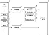
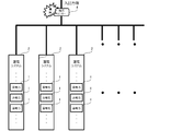
- FIG. 1 is a configuration diagram showing an outline of the internal state estimation system of the present embodiment.
- the internal state estimation system of this embodiment is connected to a power storage system unit 2 including a plurality of storage batteries 1.
- the voltage of each storage battery 1 constituting the power storage system unit 2 is measured, and the system cell voltage is determined by adding weight to the voltage. Based on the determined system cell voltage and the current flowing through each storage battery, the system SOC of the power storage system is estimated.
- the internal state estimation system includes a voltage measurement unit 3, a current measurement unit 4, a system cell voltage determination unit 5, and a system SOC estimation unit 6 in order to estimate the system SOC.
- the power storage system unit 2 to be estimated is one in which a plurality of storage batteries 1 are electrically connected, and the rated capacity and rated output are larger than those of a single storage battery 1.
- the storage battery 1 is a so-called secondary battery, and is a battery that can be repeatedly charged and discharged.
- a method for connecting the storage batteries 1 in the power storage system unit 2 a multi-series in which a plurality of storage batteries 1 are connected in series, another parallel connection in which a plurality of storage batteries 1 are connected in parallel, or a plurality of groups in which the storage batteries 1 are multi-series connected in parallel.
- a multi-parallel multi-series connected to can be employed.
- the voltages of all the storage batteries 1 constituting the power storage system unit 2 are measured.
- the voltage measuring unit 3 measures the voltage V by an arbitrary method. For example, when the storage battery 1 to be measured has the power storage system unit 2 configured by m storage batteries 1, the voltage values V1 to m are measured, and the measured voltage values V1 to m of the individual storage batteries 1 are Is output to the system cell voltage determination unit 5.
- the current measuring unit 4 measures individual currents flowing through the individual storage batteries 1 in the power storage system unit 2. An arbitrary method is used as a method for measuring the current flowing through each storage battery 1. The current information of each storage battery 1 measured by the current measuring unit 4 is output to the system SOC estimating unit 6.
- the system cell voltage determination unit 5 determines the system cell voltage Vsys of the power storage system unit 2 using the voltage values V 1 to m of the storage battery 1 sent from the voltage measurement unit 3.
- the system cell voltage Vsys is a voltage used for estimating the SOC of the power storage system unit 2.
- the system cell voltage determining unit 5 selects one of the voltage values V1 to m of the storage battery 1 and adds a weight according to the previously calculated system SOC of the power storage system unit 2 to obtain the system cell voltage Vsys. .
- Any value selected from the voltage values V1 to m of the storage battery 1 includes a maximum voltage value (hereinafter referred to as maximum voltage Vmax) and a minimum voltage value (hereinafter referred to as minimum voltage Vmin) among the voltage values V1 to m. To do.
- the system cell voltage determination unit 5 includes a voltage value storage unit 51, a voltage value selection unit 52, and a determination condition storage unit 53 in order to determine the system cell voltage Vsys.
- the voltage value storage unit 51 stores the voltage values V1 to Vm of the storage battery 1 sent from the voltage measurement unit 3.
- the voltage values V1 to m to be stored are all the storage batteries 1 of the power storage system unit 2 for each hour, for example, the voltage values Vt1 to Vtm at the time t1 are stored.
- the voltage value selection unit 52 selects a voltage value to be used when determining the system cell voltage Vsys.
- the voltage value selection unit 52 selects the maximum voltage Vmax from the voltage values at a certain time stored in the voltage value storage unit 51. And the minimum voltage Vmin. For example, when the voltage values Vt1 to Vtm at time t1 are stored in the voltage value storage unit 51, the maximum voltage value among the voltage values Vt1 to Vtm is set to the maximum voltage Vmax, and the minimum voltage value is set to the minimum voltage. Vmin.
- the determination condition storage unit 53 stores a condition for applying weighting to the selected voltage value.
- the weighting it is preferable that the maximum voltage Vmax is dominant when the system SOC of the power storage system unit 2 is high, and the minimum voltage Vmin is dominant when the system SOC is low and low.
- the determination condition storage unit 53 stores this equation (1).
- the weighting conditions stored in the determination condition storage unit 53 may be changed according to the configuration of the power storage system unit 2 to be installed, the installation location, and the like. Therefore, a plurality of conditions for determining the system cell voltage Vsys can be stored in the determination condition storage unit 53. For example, the following conditions can be stored.
- the weighting patterns stored in the determination condition storage unit 53 are as follows.
- Pattern 1 When the SOC region to be charged / discharged is a low SOC region, the minimum voltage is predominantly adopted, and when the SOC region is a high SOC region, the maximum voltage is predominantly adopted.
- the minimum voltage value and the maximum voltage value are weighted according to the system SOC calculated in advance.
- Vsys can be expressed by the following equation. [Formula 2]
- Pattern 2 When the SOC region to be charged / discharged is less than the threshold A, the minimum voltage is adopted, and when the SOC region is more than the threshold A, the maximum voltage is adopted.
- the voltage value adopted as the system cell voltage Vsys is switched from the minimum voltage value to the maximum voltage value or from the maximum voltage value to the minimum voltage value according to the system SOC value of the power storage system unit 2 calculated in advance. That is, when the SOC value is less than the threshold value A, the minimum voltage is adopted, and when the SOC value is more than the threshold value A, the maximum voltage is adopted.
- Vsys can be expressed by the following equation. [Formula 3]
- the threshold A can be freely set in the range of 0% to 100%.
- the storage battery voltage increases or decreases sharply.
- the increase or decrease of the storage battery voltage becomes relatively slow except at the end of charging and discharging.
- the increase or decrease in the storage battery voltage becomes severe, the difference in voltage value between the storage batteries 1 in each power storage system unit 2 increases, so that the value of the system cell voltage Vsys calculated based on that value also changes greatly. Therefore, it is preferable to set the threshold value A within a range where the increase or decrease of the storage battery voltage is relatively gradual.
- the range is 20% to 80%.
- This range is just an example, and depending on the type of storage battery 1, there is a range in which the increase or decrease of the storage battery voltage is relatively gradual 30% to 60%. It is desirable to set the threshold value A according to the type of the storage battery 1 to be used.
- Pattern 3 When the SOC region to be charged / discharged is less than the threshold A, the minimum voltage is adopted.
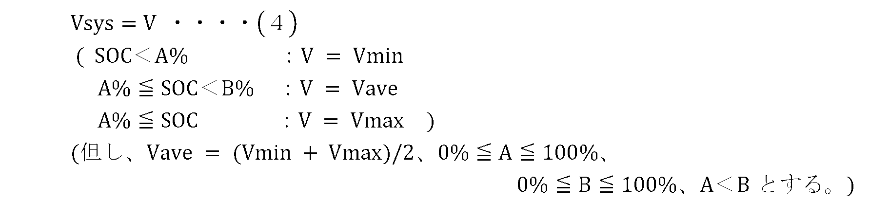
- the voltage information value adopted according to the SOC of the power storage system unit 2 is switched to three. That is, as the system cell voltage Vsys, the minimum voltage value is adopted when the SOC of the power storage system unit 2 is near the minimum value, the average voltage value is adopted when the SOC of the power storage system unit 2 is near the center, and the SOC of the power storage system unit 2 is The maximum voltage value is adopted near the maximum value.
- Vsys can be expressed by the following equation. [Formula 4]
- the threshold A is smaller than the threshold B, it can be freely set in the range of 0% to 100%.
- the threshold A and the threshold B are set in a range where the increase or decrease in the storage battery voltage is relatively gradual, as in the case of the pattern 1. Further, it is desirable that the interval between the threshold A and the threshold B is set with a constant interval.
- the system cell voltage Vsys determined by any of the methods 1 to 3 as described above is transmitted to the system SOC estimation unit 6 connected to the system cell voltage determination unit 5.
- the system SOC estimation unit 6 estimates the SOC in the power storage system unit 2 based on the input system cell voltage Vsys and the current value of each storage battery 1 measured by the current measurement unit 4.
- the SOC in the power storage system unit 2 is calculated by calculating the SOC for one series from the current value flowing in one series, and calculating the average value of each series SOC in the SOC in the power storage system unit 2
- the estimation of the SOC in the power storage system unit 2 may be adopted using the average value of the currents flowing in other parallel.
- the system SOC estimated here is a value indicating the internal state of the power storage system unit 2.
- An arbitrary method can be adopted as the system SOC estimation method in the system SOC estimation unit 6.
- the SOC is calculated using the characteristic data of the storage battery so that the battery equivalent circuit model composed of a resistor and a capacitor is used or the SOC is calculated based on the relational data between the OCV and the SOC. calculate.
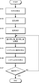
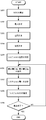
- FIG. 2 is a flowchart illustrating steps in estimating the internal state of the power storage system unit 2 in the internal state estimation system.
- a temporary system SOC is calculated (S101).
- a pre-calculated system SOC is necessary for estimating the system SOC. If the system SOC has already been estimated, the estimated system SOC can be used. However, the system SOC is not estimated at the start of the system operation. Therefore, the system SOC at the start of estimation of the internal state is calculated using another method.
- the method for calculating the system SOC at the start of internal state estimation can be performed using a known method.
- the SOC estimated based on the relationship between the open circuit voltage and the SOC value in the power storage system unit 2 may be used.
- the internal state estimation system acquires voltage value information of all the storage batteries 1 constituting the power storage system unit 2 (S102).
- the obtained voltage information is sent to the voltage value storage unit 51 in the system cell voltage determination unit 5 as the voltage value of the storage battery 1.
- the internal state estimation system acquires current information flowing through all the storage batteries 1 constituting the power storage system unit 2 (S103).
- the obtained current information is sent to the system SOC estimation unit 6 as the current value of the storage battery 1.
- the system cell voltage determination unit 5 weights the voltage value stored in the voltage value storage unit 51 according to the SOC of the power storage system unit 2 calculated in advance. At this time, the maximum voltage value and the minimum voltage value are selected from the voltage values of each storage battery 1 for each time as a voltage to be weighted (S104). Further, the system cell voltage determination unit 5 determines the system cell voltage Vsys by adding a weight to the maximum voltage value and the minimum voltage value based on the weighting condition for the selected voltage value (S105). .
- the system SOC in the power storage system unit 2 is estimated (S106).
- the system cell voltage Vsys is determined by adding a weight to the voltage value stored in the voltage value storage unit 51 based on the system SOC estimated in S106.
- the system SOC in the power storage system unit 2 is estimated based on the system cell voltage Vsys and current information flowing through the power storage system unit 2. This S104 to S106 are repeated, and the system SOC is continuously estimated until the estimation is completed (YES in S107).
- the system SOC of the power storage system can be estimated through the above processes. Further, in determining the system cell voltage Vsys, it is possible to change the weighting condition for each pattern. Below, operation
- the SOC of the power storage system unit 2 is determined by weighting the minimum voltage value and the maximum voltage value according to the system SOC calculated in advance.
- the weight for the minimum voltage is increased, and when the SOC of the power storage system unit 2 is estimated to be in the high SOC region, the weight for the maximum voltage is increased.
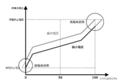
- FIG. 3 is a graph showing the system cell voltage Vsys determined based on the pattern 1 weighting condition.
- the system cell voltage Vsys matches the minimum voltage Vmin.
- the minimum voltage Vmin coincides with the discharge end voltage.
- the line indicating the system cell voltage Vsys is located at a position close to the minimum voltage Vmin.
- the system cell voltage Vsys moves away from the minimum voltage Vmin side and shifts to the maximum voltage Vmax side.
- the maximum voltage Vmax is weighted by 70 [%]
- the minimum voltage Vmin is weighted by 30 [%].
- the line indicating the system cell voltage Vsys is located at a position close to the maximum voltage Vmax.
- the maximum voltage Vmax is weighted by 100 [%], and the system cell voltage Vsys matches the maximum voltage Vmax. At this time, the maximum voltage Vmax coincides with the charge end voltage.
- the minimum voltage is employed when the SOC region to be charged / discharged is less than the threshold A, and the maximum voltage is employed when the SOC region is greater than or equal to the threshold A.
- FIG. 4 is a graph showing the system cell voltage Vsys determined based on the weighting condition of the pattern 2 when the threshold A is set to 35 [%].
- the system cell voltage Vsys matches the minimum voltage Vmin. At this time, the minimum voltage Vmin coincides with the discharge end voltage.
- the system cell voltage Vsys matches the maximum voltage Vmax.
- the system cell voltage Vsys matches the maximum voltage Vmax. At this time, the maximum voltage Vmax coincides with the charge end voltage.
- FIG. 5 is a graph showing the system cell voltage Vsys determined based on the pattern 3 weighting condition when the threshold A is 35 [%] and the threshold B is 70 [%].
- the system cell voltage Vsys matches the minimum voltage Vmin. At this time, the minimum voltage Vmin coincides with the discharge end voltage.
- the system cell voltage Vsys is an average voltage of the maximum voltage Vmax and the minimum voltage Vmin.
- the system cell voltage Vsys matches the maximum voltage Vmax.
- the system cell voltage Vsys matches the maximum voltage Vmax. At this time, the maximum voltage Vmax coincides with the charge end voltage.
- a storage battery has self-discharge, and the amount thereof varies depending on each storage battery. Therefore, the voltage of the storage battery 1 constituting the power storage system varies, and the maximum voltage and the minimum voltage can be acquired.
- the SOC estimated using either one is used as the system SOC, but in that case, there is a possibility that the estimation error becomes large at the end of discharging or at the end of charging.
- the power storage system when the maximum voltage is used for estimation, the behavior near the end of charging is not a problem because the maximum voltage reaches the end-of-charge voltage first, but the behavior near the end of discharging is the minimum voltage.
- the discharge end voltage is reached first.
- the power storage system In order to avoid overdischarge, the power storage system generally sets the system SOC to 0 [%], but a gap occurs because the maximum voltage has not yet reached the discharge end voltage.
- the estimated system SOC may contain more errors.
- the minimum voltage is used for estimation, a gap is similarly generated.
- a method of estimating the SOC of all the storage batteries 1 and setting the average value as the system SOC can be considered, but for a large-scale power storage system, calculation must be performed for each of many storage batteries. Therefore, the calculation amount may increase.
- the voltage value of the storage battery 1 of the power storage system unit 2 measured according to the system SOC value of the power storage system unit 2 calculated in advance is weighted to obtain the system cell voltage Vsys. Weighting determines a system cell voltage Vsys that predominantly uses the minimum voltage near the end of discharge and predominantly uses the maximum voltage near the end of charge. Thereby, it becomes possible to use a voltage value according to the state of the power storage system for estimation of the system SOC, and it is possible to prevent overdischarge and overcharge.
- the system cell voltage Vsys is used for system SOC estimation of the power storage system.
- the system cell voltage Vsys is obtained by weighting the maximum voltage and the minimum voltage of the storage battery 1 constituting the power storage system. For this reason, it is possible to calculate the system cell voltage Vsys from the work of selecting the maximum and minimum values from a plurality of data and the two data of the selected maximum and minimum voltage values. It is possible to estimate the SOC.
- the system cell voltage Vsys can be determined using a plurality of weighting conditions. Therefore, it is possible to estimate the system SOC with higher accuracy by selecting the optimum weighting according to the configuration of the power storage system unit 2, the arrangement location, and the like.
- the minimum voltage is employed when the SOC region to be charged / discharged is less than the threshold A
- the maximum voltage is employed when the SOC region is greater than or equal to the threshold A.
- the minimum voltage is adopted when the SOC region to be charged / discharged is less than the threshold A
- the maximum voltage is adopted when the SOC region is greater than or equal to the threshold B
- the average voltage is adopted for the region therebetween.
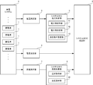
- FIG. 7 is a block diagram showing the configuration of the internal state estimation system according to the present embodiment.
- the internal state estimation system of the present embodiment includes a temperature measurement unit 7 and a system cell temperature determination unit 8 in addition to the configuration of the embodiment.
- the temperature measuring unit 7 measures the temperatures of all the storage batteries 1 constituting the power storage system unit 2.
- the temperature measuring unit 7 measures the temperature of the storage battery 1 by an arbitrary method. For example, in the case where the storage battery 1 to be measured is configured by the storage system 2 with m storage batteries 1, the temperatures T1 to m are measured, and the measured temperatures T1 to m of the individual storage batteries 1 are It is output to the cell temperature determining unit 8.
- the system cell temperature determination unit 8 determines the system cell temperature Tsys of the power storage system unit 2 using the temperatures T1 to m of the storage battery 1 sent from the temperature measurement unit 7.
- the system cell temperature Tsys is a temperature used for estimating the SOC value of the power storage system unit 2.
- the system cell temperature determination unit 8 determines the minimum temperature or the average temperature as the system cell temperature Tsys.
- the system cell temperature determination unit 8 includes a temperature storage unit 81 and a temperature selection unit 82.
- the temperature storage unit 51 stores the temperature values T1 to Tm of the storage battery 1 sent from the temperature measurement unit 7.
- the temperatures T1 to m to be stored are the temperatures of all the storage batteries 1 of the power storage system unit 2 for each hour, and for example, temperature values Tt1 to Ttm at the time t1 are stored.
- the temperature selection unit 82 selects the minimum temperature Tmin or the average Tave from the temperature values Tt1 to Ttm stored in the temperature storage unit 51 according to the temperature adopted as the system cell temperature Tsys.
- FIG. 8 is a flowchart showing steps in estimating the internal state of the power storage system unit 2 in the internal state estimation system.
- the provisional system SOC is calculated, and the voltage values and current values of all the storage batteries 1 constituting the power storage system unit 2 are measured (S201 to S203). The point is similar.
- the internal state estimation system acquires the temperatures of all the storage batteries 1 constituting the power storage system unit 2 (S204). Then, the system cell temperature Tsys corresponding to the condition is determined (S205). The determined system cell temperature Tsys is sent to the system SOC estimation unit 6 as the temperature of the storage battery 1.
- the system cell voltage determination unit 5 selects the maximum voltage value and the minimum voltage value as the voltages to be weighted, and adds the weights to the maximum voltage value and the minimum voltage value to thereby obtain the system cell voltage Vsys. Determine (S206 to S207).
- the system SOC in the power storage system unit 2 is estimated based on the system cell voltage Vsys, the system cell temperature Tsys, and the current value flowing through the power storage system unit 2 (S208).
- the system cell voltage Vsys is determined by adding a weight to the voltage value stored in the voltage value storage unit 51 based on the system SOC estimated in S208. Then, the system SOC in the power storage system unit 2 is estimated based on the system cell voltage Vsys, the system cell temperature Tsys, and current information flowing through the power storage system unit 2. These S206 to S209 are repeated, and the system SOC is continuously estimated until the estimation ends (YES in S209).
- the system cell temperature Tsys also changes according to the change in the temperature of the power storage system unit 2. Therefore, in the estimation of the system SOC by the system SOC estimation unit 6, it is possible to employ the system SOC estimation corresponding to the temperature change by giving the temperature dependence by making the resistance a function of temperature.
- the power storage system unit 2 is composed of a plurality of storage batteries 1. Therefore, if the temperature of each storage battery varies depending on the position of the storage battery relative to the power storage system, the position of the cooling device, etc., the maximum temperature, the minimum temperature, and the average temperature can be acquired.
- the SOC is calculated using that value.
- the calculated SOC is accompanied by a large error.
- the average temperature is adopted as the system cell temperature Tsys, it is possible to suppress the influence due to the abnormal value of the temperature, and it is possible to perform the SOC estimation stably and accurately.
- the temperature measurement unit 7 measures the temperature of all the storage batteries 1 constituting the power storage system unit 2, but it is necessary to provide temperature measurement means for all the storage batteries and directly measure the temperature of the storage battery. Absent.
- the temperature of the storage battery 1 may be indirectly measured by dividing the location where the storage battery 1 of the power storage system unit 2 is arranged into a plurality of blocks and measuring the temperature of the block.
- FIG. 9 is a block diagram showing the configuration of the internal state estimation system according to this embodiment.
- a current sensor 4 that is one current measurement unit 4 is installed at an input / output end of a power storage system.
- the voltage measuring unit 3 measures all the voltage values in the power storage system unit 2, but information indicating which storage battery 1 is the voltage may be added to the voltage value data. Thereby, it can be known in which position the storage battery 1 indicating the maximum voltage or the minimum voltage adopted when the system cell voltage determination unit 5 determines the system cell voltage Vsys is arranged. Then, by calculating the system SOC in consideration of the temperature of the arrangement place, it is possible to present a more accurate SOC.
Landscapes
- Physics & Mathematics (AREA)
- General Physics & Mathematics (AREA)
- Secondary Cells (AREA)
- Charge And Discharge Circuits For Batteries Or The Like (AREA)
- Engineering & Computer Science (AREA)
- Power Engineering (AREA)
- Tests Of Electric Status Of Batteries (AREA)
Abstract
Description
(1)複数の前記蓄電池における電圧を測定する電圧測定部を備える。
(2)複数の前記蓄電池を流れる電流を測定する電流測定部を備える。
(3)前記電圧測定部で計測した複数の蓄電池における電圧値に基づいて、蓄電システム部のSOCの推定の基となるシステムセル電圧を決定するシステムセル電圧決定部を備える。
(4)前記蓄電池を流れる電流とシステムセル電圧とに基づいて前記蓄電システム部のSOCの推定を行うシステムSOC推定部を備える。
(5)前記システムセル電圧決定部は、予め算出した前記蓄電システム部のSOCに応じて前記電圧値に重みづけを加えシステムセル電圧とする。
以下には、本発明の第1の実施形態である内部状態推定システムを図1~図4を用いて説明する。本実施形態の内部状態推定システムは、複数の蓄電池からなる蓄電システム部のシステムSOCの推定を行う。内部状態推定システムは、蓄電システム部におけるシステムSOCの推定を行うことで、蓄電システム部の内部状態の推定を行う。システムSOCの推定に際しては、蓄電システム部を構成する蓄電池のすべての電圧値を測定し、その中からいずれかの電圧値を選択し、選択した電圧値に対して重みづけを加えシステムセル電圧とする。システムSOCを推定する際には、このシステムセル電圧に基づいて推定を行う。
図1は、本実施形態の内部状態推定システムの概略を示す構成図である。本実施形態の内部状態推定システムは、複数の蓄電池1からなる蓄電システム部2に接続される。内部状態推定システムでは、蓄電システム部2を構成するそれぞれの蓄電池1の電圧を測定し、その電圧に対して重みづけを加えてシステムセル電圧を決定する。この決定したシステムセル電圧と、各蓄電池を流れる電流とに基づいて蓄電システムのシステムSOCを推定する。内部状態推定システムは、システムSOCを推定するために電圧測定部3、電流測定部4、システムセル電圧決定部5、システムSOC推定部6を備える。
[式1]

このパターンでは、予め算出したシステムSOCに応じて最小電圧値及び最大電圧値に対して重みづけを行う。この場合は、Vsysは、以下の式で表すことができる。
[式2]

このパターンでは、予め算出した蓄電システム部2のシステムSOC値に応じて、システムセル電圧Vsysとして採用する電圧値を最小電圧値から最大電圧値へ、若しくは最大電圧値から最小電圧値へ切り替える。すなわち、SOC値が閾値A未満の場合には最小電圧を採用し、閾値A以上の場合は最大電圧を採用する。この場合、Vsysは、以下の式で表すことができる。
[式3]

このパターンでは、蓄電システム部2のSOCに応じて採用する電圧情報値を3つに切り替える。すなわち、システムセル電圧Vsysとして、蓄電システム部2のSOCが最小値付近では最小電圧値を採用し、蓄電システム部2のSOCが中央付近では平均電圧値を採用し、蓄電システム部2のSOCが最大値付近では最大電圧値を採用する。この場合、Vsysは、以下の式で表すことができる。
[式4]
以上のような構成を有する図1の内部状態推定システムの動作の概略は次の通りである。図2は、内部状態推定システムにおける蓄電システム部2の内部状態の推定の際の工程を示すフローチャートである。
決定条件記憶部53に記憶されるパターン1の重みづけの条件では、予め算出したシステムSOCに応じて最小電圧値及び最大電圧値に対して重みづけを行うことで、蓄電システム部2のSOCが低SOC領域にあると推定される場合は前記最小電圧に対する重みづけを大きくし、蓄電システム部2のSOCが高SOC領域にあると推定される場合は前記最大電圧に対する重みづけを大きくする。
[式5]

決定条件記憶部53に記憶されるパターン2の重みづけの条件では、充放電するSOC領域が閾値A未満の場合は最小電圧を採用し、閾値A以上の場合は最大電圧を採用する。
決定条件記憶部53に記憶されるパターン3の重みづけの条件では、充放電するSOC領域が閾値A未満の場合は最小電圧を採用し、閾値B以上の場合は最大電圧を採用し、その間の領域は平均電圧を採用する。
以上のような構成及び作用を有する本実施形態によれば、以下のような効果を奏する。
[2-1.構成]
内部状態推定システムの第2実施形態について説明する。第2の実施形態では、システムSOCを推定する際に、蓄電システムの温度に即したシステムセル温度Tsysを採用することで、より正確なシステムSOCの推定を行うものである。なお、第1実施形態と同一の構成には同一の符号を付し、重複する説明は省略する。
以上のような構成を有する図7の内部状態推定システムの動作の概略は次の通りである。図8は、内部状態推定システムにおける蓄電システム部2の内部状態の推定の際の工程を示すフローチャートである。
以上のような構成及び作用を有する本実施形態によれば、以下のような効果を奏する。
[3-1.構成]
内部状態推定システムの第3実施形態について説明する。第3実施形態では、蓄電システムの電流の測定方法を前記各実施形態より変更したものである。なお、前記各実施形態と同一の構成には同一の符号を付し、重複する説明は省略する。
以上の様な構成を有する本実施形態の内部状態推定システムでは、蓄電システムの入出力端の電流を測定し、計測した電流を基に蓄電システム内の蓄電池1を流れる電流を算出している。つまり、蓄電システム部2における蓄電池1が多並列多直列に接続される場合には、計測した電流値を並列数で除することで各蓄電池1に流れる電流値を算出することが可能となる。これにより、各実施形態の効果に加えて、電流センサー点数低減、データ通信の煩雑さ低減、演算用CPUの演算量低減などが可能となる。
本明細書においては、本発明に係る複数の実施形態を説明したが、これらの実施形態は例として提示したものであって、発明の範囲を限定することを意図していない。具体的には、発明の範囲を逸脱しない範囲で、種々の省略や置き換え、変更を行うことができる。これらの実施形態やその変形は、発明の範囲や要旨に含まれると同様に、請求の範囲に記載された発明とその均等の範囲に含まれるものである。
2… 蓄電システム部
3… 電圧測定部
4… 電流測定部
5… システムセル電圧決定部
51… 電圧値記憶部
52… 電圧値選択部
53… 決定条件記憶部
6… システムSOC推定部
7… 温度計測部
8… システムセル温度決定部
81… 温度記憶部
82… 温度選択部
Claims (11)
- 複数の蓄電池からなる蓄電システム部のシステムSOCの推定を行う内部状態推定システムにおいて、
複数の前記蓄電池における電圧を測定する電圧測定部と、
複数の前記蓄電池を流れる電流を測定する電流測定部と、
前記電圧測定部で計測した複数の蓄電池における電圧値に基づいて、蓄電システム部のSOCの推定の基となるシステムセル電圧を決定するシステムセル電圧決定部と、
前記蓄電池を流れる電流とシステムセル電圧とに基づいて前記蓄電システム部のSOCの推定を行うシステムSOC推定部と、
を備え、
前記システムセル電圧決定部は、予め算出した前記蓄電システム部のSOCに応じて前記電圧値に重みづけを加えシステムセル電圧とすることを特徴とする内部状態推定システム。 - 前記システムセル電圧決定部は、
電圧測定部で測定した複数の蓄電池の時間ごとの電圧値を記憶する電圧値記憶部と、
電圧値記憶部に記憶した電圧値の中から最大電圧値と最小電圧値とを選択する電圧値選択部と、
前記最大電圧値と前記最小電圧値に加える重みづけの条件を記憶する決定条件記憶部と、
を備えることを特徴とする請求項1に記載の内部状態推定システム。 - 前記決定条件記憶部は、
前記蓄電システム部の充放電が低SOC領域で行われる場合は前記最小電圧に対する重みづけを大きくし、
充放電が高SOC領域で行わる場合には前記最大電圧に対する重みづけを大きくする重みづけ条件を記憶することを特徴とする請求項2に記載の内部状態推定システム。 - 前記決定条件記憶部は、
前記蓄電システム部のSOCにおける第1の閾値を記憶し、
前記蓄電システム部のSOCが前記第1の閾値未満の場合には前記最小電圧がシステムセル電圧となり、前記蓄電システム部のSOC値が前記第1の閾値以上の場合には前記最大電圧がシステムセル電圧となる重みづけの条件を記憶することを特徴とする請求項2に記載の内部状態推定システム。 - 前記決定条件記憶部は、
前記蓄電システム部のSOCにおける第1及び第2の閾値を記憶し、
前記蓄電システム部のSOCが前記第1の閾値未満の場合には前記最小電圧をシステムセル電圧し、
前記蓄電システム部のSOCが前記第1の閾値以上、且つ第2の閾値未満の場合は複数の蓄電池における電圧値の平均値である平均電圧をシステムセル電圧し、
前記蓄電システム部のSOCが前記第2の閾値以上の場合には前記最大電圧をシステムセル電圧とする重みづけの条件を記憶することを特徴とする請求項2に記載の内部状態推定システム。 - 前記第1の閾値及び/または第2の閾値は、前記蓄電システム部の充放電曲線における傾きが緩い領域に設定されることを特徴とする請求項4または請求項5に記載の内部状態推定システム。
- 前記複数の前記蓄電池の温度を測定する温度測定部と、
蓄電システム部のSOCの推定の基となるシステムセル温度を決定するシステムセル温度決定部と、
を更に備え、
前記システムSOC推定部は、前記蓄電池を流れる電流、システムセル電圧、及びシステムセル温度に基づいて前記蓄電システム部のSOCの推定を行うことを特徴とする請求項1乃至6のいずれか1項に記載の内部状態推定システム。 - 前記電流測定部は、前記蓄電システム部の1か所に設置され、
設置場所で計測される電流値に基づいて、前記電流測定部を構成する前記蓄電池に流れる電流値を算出することを特徴とする請求項1乃至7のいずれか1項に記載の内部状態推定システム。 - 予め算出した前記蓄電システム部のSOCとして、システムSOC推定部で推定した前記蓄電システム部のSOCを使用することを特徴とする請求項1乃至8のいずれか1項に記載の内部状態推定システム。
- 予め算出した前記蓄電システム部のSOCとして、前記蓄電システム部における開回路電圧とSOCの関係に基づいて推定したSOCを使用することを特徴とする請求項1乃至9のいずれか1項に記載の内部状態推定システム。
- 複数の蓄電池からなる蓄電システム部のSOCの推定を行う内部状態推定方法において、
複数の前記蓄電池における電圧を測定する電圧測定工程と、
複数の前記蓄電池を流れる電流を測定する電流測定工程と、
計測した複数の蓄電池における電圧値に基づいて、蓄電システム部のSOCの推定の基となるシステムセル電圧を決定するシステムセル電圧決定工程と、
前記蓄電池を流れる電流とシステムセル電圧とに基づいて前記蓄電システム部のSOCの推定を行うシステムSOC推定工程と、
を含み、
前記システムセル電圧決定工程では、予め算出した前記蓄電システム部のSOCに応じて前記電圧値に重みづけを加えシステムセル電圧とすることを特徴とする内部状態推定方法。
Priority Applications (5)
| Application Number | Priority Date | Filing Date | Title |
|---|---|---|---|
| EP15756541.7A EP3173805B1 (en) | 2014-07-25 | 2015-02-24 | Internal state estimation system and estimation method |
| JP2015545559A JP6367217B2 (ja) | 2014-07-25 | 2015-02-24 | 内部状態推定システム、及びその推定方法 |
| KR1020157024152A KR101717001B1 (ko) | 2014-07-25 | 2015-02-24 | 내부 상태 추정 시스템 및 그 추정 방법 |
| CN201580000407.7A CN105745552A (zh) | 2014-07-25 | 2015-02-24 | 内部状态推测系统及其推测方法 |
| US14/842,477 US10338152B2 (en) | 2014-07-25 | 2015-09-01 | Internal condition estimating system and estimating method |
Applications Claiming Priority (2)
| Application Number | Priority Date | Filing Date | Title |
|---|---|---|---|
| JP2014-151904 | 2014-07-25 | ||
| JP2014151904 | 2014-07-25 |
Related Child Applications (1)
| Application Number | Title | Priority Date | Filing Date |
|---|---|---|---|
| US14/842,477 Continuation US10338152B2 (en) | 2014-07-25 | 2015-09-01 | Internal condition estimating system and estimating method |
Publications (1)
| Publication Number | Publication Date |
|---|---|
| WO2016013241A1 true WO2016013241A1 (ja) | 2016-01-28 |
Family
ID=55162780
Family Applications (1)
| Application Number | Title | Priority Date | Filing Date |
|---|---|---|---|
| PCT/JP2015/055164 Ceased WO2016013241A1 (ja) | 2014-07-25 | 2015-02-24 | 内部状態推定システム、及びその推定方法 |
Country Status (6)
| Country | Link |
|---|---|
| US (1) | US10338152B2 (ja) |
| EP (1) | EP3173805B1 (ja) |
| JP (1) | JP6367217B2 (ja) |
| KR (1) | KR101717001B1 (ja) |
| CN (2) | CN110221228A (ja) |
| WO (1) | WO2016013241A1 (ja) |
Cited By (3)
| Publication number | Priority date | Publication date | Assignee | Title |
|---|---|---|---|---|
| WO2018079164A1 (ja) * | 2016-10-26 | 2018-05-03 | 日立オートモティブシステムズ株式会社 | 電池制御装置 |
| JP2018119839A (ja) * | 2017-01-24 | 2018-08-02 | 日本電気株式会社 | 蓄電制御装置、サーバ、蓄電制御方法及びプログラム |
| JP2022532105A (ja) * | 2019-09-11 | 2022-07-13 | エルジー エナジー ソリューション リミテッド | 電池診断装置および方法 |
Families Citing this family (9)
| Publication number | Priority date | Publication date | Assignee | Title |
|---|---|---|---|---|
| DE112018003701T5 (de) * | 2017-07-19 | 2020-04-02 | Mitsubishi Electric Corporation | Speicherbatteriesystem-ladesteuerungseinrichtung, speicherbatteriesystem und speicherbatterie-ladesteuerungsverfahren |
| KR102200550B1 (ko) | 2017-10-10 | 2021-01-07 | 주식회사 엘지화학 | 이차 전지의 충전 상태를 추정하기 위한 장치 |
| KR102824995B1 (ko) * | 2019-04-19 | 2025-06-24 | 주식회사 엘지에너지솔루션 | 비파괴 저항 분석을 이용한 배터리 관리 장치 및 방법 |
| JP7346155B2 (ja) * | 2019-08-21 | 2023-09-19 | 東芝エネルギーシステムズ株式会社 | 電池容量推定装置、電池容量推定方法、及びプログラム |
| JP7191873B2 (ja) * | 2020-01-17 | 2022-12-19 | 株式会社東芝 | 充放電制御装置、充放電システム、充放電制御方法及び充放電制御プログラム |
| JP7372295B2 (ja) * | 2021-09-30 | 2023-10-31 | 横河電機株式会社 | 診断装置、診断方法及び診断プログラム |
| KR102931475B1 (ko) * | 2022-01-14 | 2026-02-25 | 주식회사 엘지에너지솔루션 | 배터리 상태 추정 방법 및 그 방법을 제공하는 배터리 시스템 |
| JP7522147B2 (ja) * | 2022-02-18 | 2024-07-24 | 本田技研工業株式会社 | バッテリユニット |
| TWI866392B (zh) * | 2023-08-15 | 2024-12-11 | 台達電子工業股份有限公司 | 用於儲能系統的異常偵測方法、功率調節系統及溫度預測裝置 |
Citations (4)
| Publication number | Priority date | Publication date | Assignee | Title |
|---|---|---|---|---|
| JP2001153935A (ja) * | 1999-11-26 | 2001-06-08 | Sanyo Electric Co Ltd | 組電池の残存容量表示方法 |
| JP2003070251A (ja) | 2001-08-22 | 2003-03-07 | Toshiba Corp | 電圧調整装置 |
| JP2012177588A (ja) * | 2011-02-25 | 2012-09-13 | Mitsubishi Heavy Ind Ltd | 充電率推定装置、充電率推定方法、及びプログラム |
| JP2013178202A (ja) * | 2012-02-29 | 2013-09-09 | Mitsubishi Heavy Ind Ltd | 充電率演算システムおよび充電率演算方法 |
Family Cites Families (27)
| Publication number | Priority date | Publication date | Assignee | Title |
|---|---|---|---|---|
| JP3618472B2 (ja) * | 1996-07-01 | 2005-02-09 | 富士通株式会社 | 電池ユニット及び電池ユニットを使用する装置 |
| JP3398304B2 (ja) * | 1997-07-31 | 2003-04-21 | 東芝電池株式会社 | 二次電池の電圧測定回路およびこれを用いた保護回路 |
| JP3806578B2 (ja) * | 2000-05-22 | 2006-08-09 | スズキ株式会社 | バッテリ残存容量推定装置 |
| DE10056971A1 (de) * | 2000-11-17 | 2002-05-23 | Bosch Gmbh Robert | Verfahren und Vorrichtung zur Bestimmung des Ladezustandes einer Batterie |
| US6359419B1 (en) * | 2000-12-27 | 2002-03-19 | General Motors Corporation | Quasi-adaptive method for determining a battery's state of charge |
| JP2004109191A (ja) * | 2002-09-13 | 2004-04-08 | Toshiba Corp | 平面表示装置、表示用駆動回路、および表示用駆動方法 |
| JP2006112786A (ja) * | 2004-10-12 | 2006-04-27 | Sanyo Electric Co Ltd | 電池の残容量検出方法及び電源装置 |
| JP5089883B2 (ja) | 2005-12-16 | 2012-12-05 | 日立ビークルエナジー株式会社 | 蓄電池管理装置 |
| EP1965481A2 (en) * | 2007-02-28 | 2008-09-03 | STMicroelectronics, Inc. | Integrated circuit and method for monitoring and controlling power and for detecting open load state |
| US8264207B2 (en) * | 2007-10-16 | 2012-09-11 | Ford Global Technologies, Llc | Method and system for pulse charging an automotive battery |
| US20090102672A1 (en) * | 2007-10-19 | 2009-04-23 | Honeywell International, Inc. | Features to reduce low-battery reporting to security services at night |
| KR100970841B1 (ko) * | 2008-08-08 | 2010-07-16 | 주식회사 엘지화학 | 배터리 전압 거동을 이용한 배터리 용량 퇴화 추정 장치 및방법 |
| US8823323B2 (en) * | 2009-04-16 | 2014-09-02 | Valence Technology, Inc. | Batteries, battery systems, battery submodules, battery operational methods, battery system operational methods, battery charging methods, and battery system charging methods |
| CN102062841B (zh) * | 2009-11-11 | 2012-12-12 | 北汽福田汽车股份有限公司 | 动力电池荷电状态的估测方法及系统 |
| DE102009054924A1 (de) | 2009-12-18 | 2011-06-22 | SB LiMotive Company Ltd., Kyonggi | Verfahren zur Ermittlung des Ladezustands eines Batteriepacks |
| JP5292375B2 (ja) | 2010-09-16 | 2013-09-18 | カルソニックカンセイ株式会社 | バッテリの充電率推定装置 |
| US20120109556A1 (en) * | 2010-10-29 | 2012-05-03 | GM Global Technology Operations LLC | Band select state of charge weighted scaling method |
| JP5287844B2 (ja) * | 2010-12-27 | 2013-09-11 | 株式会社デンソー | 二次電池の残存容量演算装置 |
| DE102011079159A1 (de) * | 2011-05-18 | 2012-11-22 | Fraunhofer-Gesellschaft zur Förderung der angewandten Forschung e.V. | Vorrichtung und verfahren zum bestimmen eines zustandsparameters einer batterie |
| KR101856663B1 (ko) * | 2011-06-03 | 2018-05-10 | 에스케이이노베이션 주식회사 | 다중팩 병렬 구조의 정보 교환을 위한 2차 전지 관리 시스템 및 방법 |
| CN102496970B (zh) * | 2011-11-11 | 2014-05-28 | 江苏大学 | 纯电动公交客车动力电源的soc检测及能量均衡系统与方法 |
| FR2990516B1 (fr) * | 2012-05-11 | 2015-10-16 | Renault Sas | Estimation de l'etat de charge d'une batterie |
| JP2014025739A (ja) * | 2012-07-25 | 2014-02-06 | Sanyo Electric Co Ltd | 電池状態推定装置 |
| JP2014038254A (ja) * | 2012-08-17 | 2014-02-27 | Toshiba Corp | 液晶レンズ装置及び画像表示装置及び駆動装置 |
| JP5863603B2 (ja) * | 2012-08-24 | 2016-02-16 | 日立オートモティブシステムズ株式会社 | 電池状態推定装置、電池制御装置、電池システム、電池状態推定方法 |
| CN103852725B (zh) * | 2012-11-30 | 2018-05-01 | 凹凸电子(武汉)有限公司 | 用于估算电池剩余容量的设备、方法及系统 |
| WO2014122721A1 (ja) * | 2013-02-05 | 2014-08-14 | 日立ビークルエナジー株式会社 | 電池制御装置 |
-
2015
- 2015-02-24 KR KR1020157024152A patent/KR101717001B1/ko active Active
- 2015-02-24 JP JP2015545559A patent/JP6367217B2/ja active Active
- 2015-02-24 CN CN201910535995.4A patent/CN110221228A/zh active Pending
- 2015-02-24 WO PCT/JP2015/055164 patent/WO2016013241A1/ja not_active Ceased
- 2015-02-24 CN CN201580000407.7A patent/CN105745552A/zh active Pending
- 2015-02-24 EP EP15756541.7A patent/EP3173805B1/en active Active
- 2015-09-01 US US14/842,477 patent/US10338152B2/en active Active
Patent Citations (4)
| Publication number | Priority date | Publication date | Assignee | Title |
|---|---|---|---|---|
| JP2001153935A (ja) * | 1999-11-26 | 2001-06-08 | Sanyo Electric Co Ltd | 組電池の残存容量表示方法 |
| JP2003070251A (ja) | 2001-08-22 | 2003-03-07 | Toshiba Corp | 電圧調整装置 |
| JP2012177588A (ja) * | 2011-02-25 | 2012-09-13 | Mitsubishi Heavy Ind Ltd | 充電率推定装置、充電率推定方法、及びプログラム |
| JP2013178202A (ja) * | 2012-02-29 | 2013-09-09 | Mitsubishi Heavy Ind Ltd | 充電率演算システムおよび充電率演算方法 |
Non-Patent Citations (1)
| Title |
|---|
| See also references of EP3173805A4 |
Cited By (6)
| Publication number | Priority date | Publication date | Assignee | Title |
|---|---|---|---|---|
| WO2018079164A1 (ja) * | 2016-10-26 | 2018-05-03 | 日立オートモティブシステムズ株式会社 | 電池制御装置 |
| JPWO2018079164A1 (ja) * | 2016-10-26 | 2019-09-12 | 日立オートモティブシステムズ株式会社 | 電池制御装置 |
| JP2018119839A (ja) * | 2017-01-24 | 2018-08-02 | 日本電気株式会社 | 蓄電制御装置、サーバ、蓄電制御方法及びプログラム |
| JP2022532105A (ja) * | 2019-09-11 | 2022-07-13 | エルジー エナジー ソリューション リミテッド | 電池診断装置および方法 |
| US11965936B2 (en) | 2019-09-11 | 2024-04-23 | Lg Energy Solution, Ltd. | Battery diagnosis apparatus and method |
| JP7621274B2 (ja) | 2019-09-11 | 2025-01-24 | エルジー エナジー ソリューション リミテッド | 電池診断装置および方法 |
Also Published As
| Publication number | Publication date |
|---|---|
| KR101717001B1 (ko) | 2017-03-15 |
| US10338152B2 (en) | 2019-07-02 |
| KR20160037830A (ko) | 2016-04-06 |
| US20160025814A1 (en) | 2016-01-28 |
| EP3173805B1 (en) | 2021-05-26 |
| JPWO2016013241A1 (ja) | 2017-04-27 |
| EP3173805A1 (en) | 2017-05-31 |
| CN105745552A (zh) | 2016-07-06 |
| EP3173805A4 (en) | 2018-04-04 |
| JP6367217B2 (ja) | 2018-08-01 |
| CN110221228A (zh) | 2019-09-10 |
Similar Documents
| Publication | Publication Date | Title |
|---|---|---|
| JP6367217B2 (ja) | 内部状態推定システム、及びその推定方法 | |
| JP7289113B2 (ja) | 管理装置、及び電源システム | |
| JP7217474B2 (ja) | 管理装置、及び電源システム | |
| JP7226723B2 (ja) | バッテリー管理システム、バッテリーパック、電気車両及びバッテリー管理方法 | |
| JP5466564B2 (ja) | 電池劣化推定方法、電池容量推定方法、電池容量均等化方法、および電池劣化推定装置 | |
| JP7054868B2 (ja) | 電池管理装置、電池システム、及び車両用電源システム | |
| JP7155486B2 (ja) | バッテリー管理システム、バッテリー管理方法、バッテリーパック及び電気車両 | |
| JP5863603B2 (ja) | 電池状態推定装置、電池制御装置、電池システム、電池状態推定方法 | |
| JP6844090B2 (ja) | バッテリーのための等価回路モデルのパラメータを推定する方法及びバッテリー管理システム | |
| EP3002597B1 (en) | Battery control device | |
| JP6119402B2 (ja) | 内部抵抗推定装置及び内部抵抗推定方法 | |
| CN106451592B (zh) | 电池充放电的控制方法、电池充放电的控制设备和电动车 | |
| JP6548387B2 (ja) | 二次電池の充電状態推定方法および推定装置 | |
| JP2008520179A (ja) | 充電状態を用いた電池平滑化システム及び方法 | |
| JP6749080B2 (ja) | 蓄電システム、二次電池の制御システム及び二次電池の制御方法 | |
| KR20220041045A (ko) | 배터리 성능 평가 방법 및 장치 | |
| CN104237792B (zh) | 电池容量预测方法 | |
| CN107004514B (zh) | 用于均衡能量存储器系统的方法 | |
| CN112119564A (zh) | 管理装置、蓄电系统 | |
| JP2017125680A (ja) | 電池制御装置 | |
| JP2016024170A (ja) | 電池制御装置 | |
| JP5904916B2 (ja) | バッテリの健全度算出装置および健全度算出方法 | |
| KR101835375B1 (ko) | 배터리 집단군 건강상태 추정 장치 및 그 방법 | |
| JP2016211923A (ja) | 充電量推定方法及び充電量推定装置 | |
| CN104808151B (zh) | 蓄电装置的残存容量推定装置 |
Legal Events
| Date | Code | Title | Description |
|---|---|---|---|
| ENP | Entry into the national phase |
Ref document number: 20157024152 Country of ref document: KR Kind code of ref document: A |
|
| REEP | Request for entry into the european phase |
Ref document number: 2015756541 Country of ref document: EP |
|
| WWE | Wipo information: entry into national phase |
Ref document number: 2015756541 Country of ref document: EP |
|
| ENP | Entry into the national phase |
Ref document number: 2015545559 Country of ref document: JP Kind code of ref document: A |
|
| 121 | Ep: the epo has been informed by wipo that ep was designated in this application |
Ref document number: 15756541 Country of ref document: EP Kind code of ref document: A1 |
|
| NENP | Non-entry into the national phase |
Ref country code: DE |