WO2016013331A1 - プレート一体ガスケットの製造方法 - Google Patents
プレート一体ガスケットの製造方法 Download PDFInfo
- Publication number
- WO2016013331A1 WO2016013331A1 PCT/JP2015/067227 JP2015067227W WO2016013331A1 WO 2016013331 A1 WO2016013331 A1 WO 2016013331A1 JP 2015067227 W JP2015067227 W JP 2015067227W WO 2016013331 A1 WO2016013331 A1 WO 2016013331A1
- Authority
- WO
- WIPO (PCT)
- Prior art keywords
- plate
- gasket
- cavities
- gate
- mold
- Prior art date
- Legal status (The legal status is an assumption and is not a legal conclusion. Google has not performed a legal analysis and makes no representation as to the accuracy of the status listed.)
- Ceased
Links
Images






Classifications
-
- H—ELECTRICITY
- H01—ELECTRIC ELEMENTS
- H01M—PROCESSES OR MEANS, e.g. BATTERIES, FOR THE DIRECT CONVERSION OF CHEMICAL ENERGY INTO ELECTRICAL ENERGY
- H01M8/00—Fuel cells; Manufacture thereof
- H01M8/02—Details
- H01M8/0271—Sealing or supporting means around electrodes, matrices or membranes
- H01M8/0286—Processes for forming seals
-
- B—PERFORMING OPERATIONS; TRANSPORTING
- B29—WORKING OF PLASTICS; WORKING OF SUBSTANCES IN A PLASTIC STATE IN GENERAL
- B29C—SHAPING OR JOINING OF PLASTICS; SHAPING OF MATERIAL IN A PLASTIC STATE, NOT OTHERWISE PROVIDED FOR; AFTER-TREATMENT OF THE SHAPED PRODUCTS, e.g. REPAIRING
- B29C45/00—Injection moulding, i.e. forcing the required volume of moulding material through a nozzle into a closed mould; Apparatus therefor
- B29C45/14—Injection moulding, i.e. forcing the required volume of moulding material through a nozzle into a closed mould; Apparatus therefor incorporating preformed parts or layers, e.g. injection moulding around inserts or for coating articles
- B29C45/14065—Positioning or centering articles in the mould
-
- B—PERFORMING OPERATIONS; TRANSPORTING
- B29—WORKING OF PLASTICS; WORKING OF SUBSTANCES IN A PLASTIC STATE IN GENERAL
- B29C—SHAPING OR JOINING OF PLASTICS; SHAPING OF MATERIAL IN A PLASTIC STATE, NOT OTHERWISE PROVIDED FOR; AFTER-TREATMENT OF THE SHAPED PRODUCTS, e.g. REPAIRING
- B29C45/00—Injection moulding, i.e. forcing the required volume of moulding material through a nozzle into a closed mould; Apparatus therefor
- B29C45/14—Injection moulding, i.e. forcing the required volume of moulding material through a nozzle into a closed mould; Apparatus therefor incorporating preformed parts or layers, e.g. injection moulding around inserts or for coating articles
- B29C45/14336—Coating a portion of the article, e.g. the edge of the article
-
- F—MECHANICAL ENGINEERING; LIGHTING; HEATING; WEAPONS; BLASTING
- F16—ENGINEERING ELEMENTS AND UNITS; GENERAL MEASURES FOR PRODUCING AND MAINTAINING EFFECTIVE FUNCTIONING OF MACHINES OR INSTALLATIONS; THERMAL INSULATION IN GENERAL
- F16J—PISTONS; CYLINDERS; SEALINGS
- F16J15/00—Sealings
- F16J15/02—Sealings between relatively-stationary surfaces
- F16J15/06—Sealings between relatively-stationary surfaces with solid packing compressed between sealing surfaces
- F16J15/10—Sealings between relatively-stationary surfaces with solid packing compressed between sealing surfaces with non-metallic packing
- F16J15/108—Special methods for making a non-metallic packing
-
- H—ELECTRICITY
- H01—ELECTRIC ELEMENTS
- H01M—PROCESSES OR MEANS, e.g. BATTERIES, FOR THE DIRECT CONVERSION OF CHEMICAL ENERGY INTO ELECTRICAL ENERGY
- H01M8/00—Fuel cells; Manufacture thereof
- H01M8/02—Details
- H01M8/0271—Sealing or supporting means around electrodes, matrices or membranes
- H01M8/028—Sealing means characterised by their material
- H01M8/0284—Organic resins; Organic polymers
-
- B—PERFORMING OPERATIONS; TRANSPORTING
- B29—WORKING OF PLASTICS; WORKING OF SUBSTANCES IN A PLASTIC STATE IN GENERAL
- B29C—SHAPING OR JOINING OF PLASTICS; SHAPING OF MATERIAL IN A PLASTIC STATE, NOT OTHERWISE PROVIDED FOR; AFTER-TREATMENT OF THE SHAPED PRODUCTS, e.g. REPAIRING
- B29C45/00—Injection moulding, i.e. forcing the required volume of moulding material through a nozzle into a closed mould; Apparatus therefor
- B29C45/14—Injection moulding, i.e. forcing the required volume of moulding material through a nozzle into a closed mould; Apparatus therefor incorporating preformed parts or layers, e.g. injection moulding around inserts or for coating articles
- B29C45/14065—Positioning or centering articles in the mould
- B29C2045/14098—Positioning or centering articles in the mould fixing or clamping inserts having variable dimensions
-
- B—PERFORMING OPERATIONS; TRANSPORTING
- B29—WORKING OF PLASTICS; WORKING OF SUBSTANCES IN A PLASTIC STATE IN GENERAL
- B29C—SHAPING OR JOINING OF PLASTICS; SHAPING OF MATERIAL IN A PLASTIC STATE, NOT OTHERWISE PROVIDED FOR; AFTER-TREATMENT OF THE SHAPED PRODUCTS, e.g. REPAIRING
- B29C45/00—Injection moulding, i.e. forcing the required volume of moulding material through a nozzle into a closed mould; Apparatus therefor
- B29C45/14—Injection moulding, i.e. forcing the required volume of moulding material through a nozzle into a closed mould; Apparatus therefor incorporating preformed parts or layers, e.g. injection moulding around inserts or for coating articles
- B29C45/14336—Coating a portion of the article, e.g. the edge of the article
- B29C2045/14459—Coating a portion of the article, e.g. the edge of the article injecting seal elements
-
- B—PERFORMING OPERATIONS; TRANSPORTING
- B29—WORKING OF PLASTICS; WORKING OF SUBSTANCES IN A PLASTIC STATE IN GENERAL
- B29K—INDEXING SCHEME ASSOCIATED WITH SUBCLASSES B29B, B29C OR B29D, RELATING TO MOULDING MATERIALS OR TO MATERIALS FOR MOULDS, REINFORCEMENTS, FILLERS OR PREFORMED PARTS, e.g. INSERTS
- B29K2021/00—Use of unspecified rubbers as moulding material
-
- B—PERFORMING OPERATIONS; TRANSPORTING
- B29—WORKING OF PLASTICS; WORKING OF SUBSTANCES IN A PLASTIC STATE IN GENERAL
- B29K—INDEXING SCHEME ASSOCIATED WITH SUBCLASSES B29B, B29C OR B29D, RELATING TO MOULDING MATERIALS OR TO MATERIALS FOR MOULDS, REINFORCEMENTS, FILLERS OR PREFORMED PARTS, e.g. INSERTS
- B29K2905/00—Use of metals, their alloys or their compounds, as mould material
-
- B—PERFORMING OPERATIONS; TRANSPORTING
- B29—WORKING OF PLASTICS; WORKING OF SUBSTANCES IN A PLASTIC STATE IN GENERAL
- B29K—INDEXING SCHEME ASSOCIATED WITH SUBCLASSES B29B, B29C OR B29D, RELATING TO MOULDING MATERIALS OR TO MATERIALS FOR MOULDS, REINFORCEMENTS, FILLERS OR PREFORMED PARTS, e.g. INSERTS
- B29K2995/00—Properties of moulding materials, reinforcements, fillers, preformed parts or moulds
- B29K2995/0037—Other properties
- B29K2995/0046—Elastic
-
- B—PERFORMING OPERATIONS; TRANSPORTING
- B29—WORKING OF PLASTICS; WORKING OF SUBSTANCES IN A PLASTIC STATE IN GENERAL
- B29L—INDEXING SCHEME ASSOCIATED WITH SUBCLASS B29C, RELATING TO PARTICULAR ARTICLES
- B29L2031/00—Other particular articles
- B29L2031/26—Sealing devices, e.g. packaging for pistons or pipe joints
- B29L2031/265—Packings, Gaskets
-
- B—PERFORMING OPERATIONS; TRANSPORTING
- B29—WORKING OF PLASTICS; WORKING OF SUBSTANCES IN A PLASTIC STATE IN GENERAL
- B29L—INDEXING SCHEME ASSOCIATED WITH SUBCLASS B29C, RELATING TO PARTICULAR ARTICLES
- B29L2031/00—Other particular articles
- B29L2031/34—Electrical apparatus, e.g. sparking plugs or parts thereof
- B29L2031/3468—Batteries, accumulators or fuel cells
-
- H—ELECTRICITY
- H01—ELECTRIC ELEMENTS
- H01M—PROCESSES OR MEANS, e.g. BATTERIES, FOR THE DIRECT CONVERSION OF CHEMICAL ENERGY INTO ELECTRICAL ENERGY
- H01M8/00—Fuel cells; Manufacture thereof
- H01M8/02—Details
- H01M8/0202—Collectors; Separators, e.g. bipolar separators; Interconnectors
- H01M8/0247—Collectors; Separators, e.g. bipolar separators; Interconnectors characterised by the form
- H01M8/0254—Collectors; Separators, e.g. bipolar separators; Interconnectors characterised by the form corrugated or undulated
-
- H—ELECTRICITY
- H01—ELECTRIC ELEMENTS
- H01M—PROCESSES OR MEANS, e.g. BATTERIES, FOR THE DIRECT CONVERSION OF CHEMICAL ENERGY INTO ELECTRICAL ENERGY
- H01M8/00—Fuel cells; Manufacture thereof
- H01M8/02—Details
- H01M8/0271—Sealing or supporting means around electrodes, matrices or membranes
- H01M8/0276—Sealing means characterised by their form
-
- Y—GENERAL TAGGING OF NEW TECHNOLOGICAL DEVELOPMENTS; GENERAL TAGGING OF CROSS-SECTIONAL TECHNOLOGIES SPANNING OVER SEVERAL SECTIONS OF THE IPC; TECHNICAL SUBJECTS COVERED BY FORMER USPC CROSS-REFERENCE ART COLLECTIONS [XRACs] AND DIGESTS
- Y02—TECHNOLOGIES OR APPLICATIONS FOR MITIGATION OR ADAPTATION AGAINST CLIMATE CHANGE
- Y02E—REDUCTION OF GREENHOUSE GAS [GHG] EMISSIONS, RELATED TO ENERGY GENERATION, TRANSMISSION OR DISTRIBUTION
- Y02E60/00—Enabling technologies; Technologies with a potential or indirect contribution to GHG emissions mitigation
- Y02E60/30—Hydrogen technology
- Y02E60/50—Fuel cells
-
- Y—GENERAL TAGGING OF NEW TECHNOLOGICAL DEVELOPMENTS; GENERAL TAGGING OF CROSS-SECTIONAL TECHNOLOGIES SPANNING OVER SEVERAL SECTIONS OF THE IPC; TECHNICAL SUBJECTS COVERED BY FORMER USPC CROSS-REFERENCE ART COLLECTIONS [XRACs] AND DIGESTS
- Y02—TECHNOLOGIES OR APPLICATIONS FOR MITIGATION OR ADAPTATION AGAINST CLIMATE CHANGE
- Y02P—CLIMATE CHANGE MITIGATION TECHNOLOGIES IN THE PRODUCTION OR PROCESSING OF GOODS
- Y02P70/00—Climate change mitigation technologies in the production process for final industrial or consumer products
- Y02P70/50—Manufacturing or production processes characterised by the final manufactured product
Definitions
- the present invention relates to a method of manufacturing a plate-integrated gasket in which a gasket body made of a rubber-like elastic material is integrally provided on both surfaces of a peripheral portion of a plate such as a separator constituting a fuel battery cell.
- a fuel cell has a gas diffusion layer disposed on both sides in the thickness direction of a membrane electrode assembly (MEA) having a pair of electrode layers on both sides of an electrolyte membrane, and a separator is stacked on the fuel cell.
- MEA membrane electrode assembly
- a stack structure in which a large number of fuel cells are stacked is used.
- Each fuel cell uses a gasket for sealing a fuel gas, an oxidizing gas, or the like.
- a plate-integrated gasket 100 as shown in FIG. 7 is conventionally known.
- the gasket main bodies 102 and 103 are integrally provided, and the gasket main bodies 102 and 103 are respectively provided with base portions 102a and 103a formed in a filling state in strip-like grooves 101a and 101b formed on both surfaces of the carbon plate 101, respectively.
- the seal lips 102b and 103b are formed so as to protrude in a mountain shape from the intermediate portion in the width direction.
- the base portions 102a and 103a on both sides in the thickness direction are integrally continuous with each other through a through hole 101d formed in a thin portion 101c between the strip-like grooves 101a and 101b of the carbon plate 101.
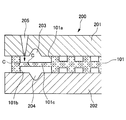
- the carbon plate 101 and the gasket main bodies 102 and 103 are integrally formed using a mold 200 as shown in FIGS. That is, first, the carbon plate 101 is positioned and arranged between the divided dies 201 and 202 of the mold 200, and is defined between the band-like grooves 101a and 101b on both surfaces of the carbon plate 101 and the divided dies 201 and 202 by clamping.
- the cavities 203 and 204 are filled with a liquid rubber material for molding.
- the gate 205 which is a supply port for the liquid rubber material, opens only in one cavity 203, but the cavities 203 and 204 communicate with each other through a through hole 101d provided in the carbon plate 101 as shown in FIG. Therefore, the liquid rubber material injected from the gate 205 into the cavity 203 flows into the cavity 204 through the through hole 101d from the cavity 203 and is shaped (see the following prior art document).
- the carbon plate 101 is brittle, there is a concern that the thin portion 101c between the strip-shaped grooves 101a and 101b may cause a crack C due to the injection pressure of the liquid rubber material from the gate 205.
- the crack C is likely to occur because the injection pressure of the liquid rubber material from the gate 205 is directly received, and as shown in FIG.
- a crack C starting from the through hole 101d may occur.
- the present invention has been made in view of the above points, and its technical problem is that when a gasket body made of a rubber-like elastic material is integrally formed on both surfaces of a plate made of a brittle material such as carbon,
- An object of the present invention is to provide a method for producing a plate-integrated gasket capable of effectively preventing cracking of a plate.
- a manufacturing method of a plate-integrated gasket according to the invention of claim 1 is a gasket made of a rubber-like elastic material on both sides in the thickness direction in a portion along the periphery of the plate.
- an area located between gasket forming cavities defined by clamping the plate by clamping the plate between divided molds of the mold. Is formed so as to be relatively thick at a position facing the opening of the gate for injecting the molding material into the cavity and in the vicinity thereof.
- the plate is formed from the gate into the gasket forming cavity defined on both sides in the thickness direction in the portion along the peripheral edge of the plate by clamping the plate between the divided molds of the mold.
- a gasket body made of a rubber-like elastic material is integrally formed on both sides in the thickness direction in the portion along the periphery of the plate.
- the plate is formed so that the region located between the cavities is relatively thick at the position facing the opening of the gate and in the vicinity thereof.
- the injection pressure of the molding material from the gate is received in a relatively thick portion of the region located between the cavities. And since this part is relatively thick and has high mechanical strength, even if the plate is made of a brittle material, it can be made difficult to cause cracks due to the injection pressure of the molding material. .
- a method for manufacturing a plate-integrated gasket according to a second aspect of the present invention is the method according to the first aspect, wherein the through-holes communicating with the cavities on both sides in the thickness direction of the plate are relatively thick. It is located in
- a method for manufacturing a plate-integrated gasket according to claim 3 is the method according to claim 1 or 2, wherein the relatively thick portion is clamped between the mold split molds. It extends from the part.
- a method of manufacturing the plate-integrated gasket according to any one of the first to third aspects wherein an extension portion in which the cavity extends in the width direction is formed in a part of the extension direction of the cavity.
- the gate is opened toward the extension portion, and a relatively thick portion of the plate in the region located between the cavities is formed so as to be located in the extension portion.
- the mechanical strength of the relatively thick portion in the region located between the cavities in the plate is further increased.
- a gasket body made of a rubber-like elastic material is integrally formed on both surfaces of a plate made of a brittle material such as carbon, the plate of the plate due to the injection pressure of the molding material from the gate is formed. Cracks can be effectively prevented.
- FIG. 5 is a cross-sectional view taken along the line A-A ′ of FIG. 4. It is explanatory drawing which shows the example of a partial change of 3rd embodiment shown in FIG.
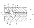
- FIG. 1 shows a first embodiment
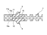
- FIG. 2 shows a plate-integrated gasket manufactured by the method according to the first embodiment.
- reference numeral 1 denotes a fuel cell as a separator.
- a plate to be incorporated, reference numeral 2 is a gasket body 3 made of a rubber-like elastic material (rubber material or a synthetic resin material having rubber-like elasticity) as shown in FIG. 4 is a mold for integrally injection-molding 4.
- the plate 1 is formed of carbon, and strip-like grooves 11 and 12 extending along the peripheral edge (outer peripheral edge and opening edge) are formed on both surfaces in the thickness direction so as to have cross-sectional shapes symmetrical to each other in the thickness direction.
- a large number of flow channel grooves 13 and 14 are formed on both sides in the thickness direction of the inner regions of the belt-shaped grooves 11 and 12 for circulating a reaction gas (fuel gas and oxidant gas) in the fuel cell. ing.
- the mold 2 includes split molds 21 and 22 that can sandwich the plate 1, that is, the plate 1 is positioned and positioned between the split molds 21 and 22 and clamped to clamp the periphery of the plate 1.
- Gasket forming cavities 23 and 24 are defined between the strip-shaped grooves 11 and 12 on both sides in the thickness direction and the split dies 21 and 22, respectively.
- the cavities 23 and 24 have a negative and positive cross-sectional shape corresponding to the gasket bodies 3 and 4 shown in FIG. 2, that is, correspond to the base portions 31 and 41 filled in the belt-like grooves 11 and 12 of the plate 1, respectively.
- Base molding parts 231 and 241 and seal lip molding parts 232 and 242 corresponding to seal lips 32 and 42 raised in a mountain shape from the widthwise intermediate part of the base parts 31 and 41. Both cavities 23 and 24 communicate with each other through a through hole (not shown) provided between the cavities 23 and 24.
- One split mold 21 is provided with a gate 25 which is a supply port for the liquid rubber material for molding.
- the opening 25a at the downstream end of the gate 25 is divided by the mold 2 being clamped.
- One cavity 23 defined between the mold 21 and the belt-like groove 11 of the plate 1 is located at the position facing the outer peripheral portion 231 a of the base molding portion 231.
- the plate 1 is a region between the cavities 23 and 24 defined by clamping the mold 2 between the split dies 21 and 22 and, in other words, a portion between the strip grooves 11 and 12.
- 15 is formed with a thick portion 15a that is relatively thick at a position facing the opening 25a of the gate 25 and in the vicinity thereof.
- the thick portion 15a is formed so as to protrude from the sandwiched portion 16 sandwiched between the split dies 21 and 22 on the outer peripheral side of the cavities 23 and 24 (band-like grooves 11 and 12). It may be continuous in the extending direction of the belt-like grooves 11, 12), that is, in the direction orthogonal to the cross section shown in the drawing.
- the molding liquid rubber material is injected into the cavities 23 and 24 defined on both sides in the thickness direction of the plate 1 in the clamped state shown in FIG. To do. Specifically, the liquid rubber material is first filled into the one cavity 23 from the gate 25 opened in the one split mold 21, and further through a not-shown through hole opened in the portion 15 between the strip grooves 11 and 12. The other cavity 23 is filled.
- the plate 1 receives the injection pressure of the liquid rubber material from the opening 25a of the gate 25 at the thick portion 15a in the portion 15 between the cavities 23 and 24 (band-like grooves 11 and 12). And this thick part 15a is a part with relatively high mechanical strength among the parts 15 between the cavities 23 and 24 (strip-like grooves 11 and 12), and the cavities 23 and 24 (strip-like grooves 11 and 12). Since the plate 1 is supported by the clamped portion 16 sandwiched between the split molds 21 and 22 on the outer peripheral side of the plate, even if the plate 1 is formed of carbon, cracking due to the injection pressure of the liquid rubber material is effectively prevented. Is done.
- the gasket bodies 3 and 4 made of a rubber-like elastic material integrated with the plate 1 are formed as shown in FIG.
- FIG. 3 shows a second embodiment of the method for manufacturing a plate-integrated gasket according to the present invention.
- the cavities on both sides in the thickness direction of the plate 1 are as follows. That is, the through-holes 17 communicating with each other 23 and 24 are opened in the relative thick portion 15a. Further, the through hole 17 is at a position facing the opening 25 a of the gate 25. In this way, the generation of cracks starting from the through holes 17 due to the injection pressure of the liquid rubber material from the gate 25 is effectively prevented.
- FIGS. 4 and 5 show a third embodiment of the method for manufacturing a plate-integrated gasket according to the present invention.
- the difference from the first embodiment described above is that the cavities 23 and 24 are shown in FIGS.
- the extended portions 233 and 243 in which the cavities 23 and 24 extend outward in the width direction are formed in a part of the extending direction of the plate 25, and the opening 25a of the gate 25 is opened to one of the extended portions 233.
- the relative thick portion 15a in the portion 15 between the cavities 23 and 24 is formed so as to be positioned between the expanded portions 233 and 243. As shown in FIG.
- the expanded portions 233 and 243 are notched in a part of the extending direction of the belt-like grooves 11 and 12 of the plate 1 and are notched shallowly toward the peripheral side of the plate 1 at a predetermined interval.
- 12a is formed between the notches 11a, 12a and the inner surface of the mold at the time of clamping, and the thick portion 15a is formed as a portion between the notches 11a, 12a. It is.
- the through-holes 17 communicating with the cavities 23 and 24 on both sides in the thickness direction of the plate 1 are opened in the thick portion 15a, in other words, located in the expanded portions 233 and 243. Further, the through hole 17 is at a position facing the opening 25 a of the gate 25.
- the portions where the liquid rubber material that has flowed into the expanded portions 233 and 243 of the cavities 23 and 24 is cross-linked and hardened are filled into the band-like grooves 11 and 12 of the plate 1 in the gasket bodies 3 and 4.
- the projecting portions 33 and 43 project from the base portions 31 and 41 in the width direction.
- the thick portion 15a of the plate 1 facing the opening 25a of the gate 25 is surrounded by the rising surfaces of the extended portions 233 and 243 (the notches 11a and 12a), in other words, the sandwiched portion 16.
- the molded plate-integrated gasket has a cross-sectional shape as shown in FIG. 5 except for the overhang portions 33 and 43, uniform sealing performance can be achieved.
- FIG. 6 shows a partial modification of the above-described third embodiment. That is, in the example of FIG. 4 described above, the cavities 23 and 24 on both sides in the thickness direction of the plate 1 are mutually connected.
- the communicating through-hole 17 is opened in the middle portion of the thick portion 15a (the extended portions 233 and 243), whereas in the modified example, it is opened near the rising surface of the extended portions 233 and 243.
- the mechanical strength of the thick portion 15a with respect to the injection pressure of the liquid rubber material from the gate 25 becomes higher, and the through hole 17 due to the injection pressure of the liquid rubber material from the gate 25 is the starting point. Generation of cracks is effectively prevented.
Landscapes
- Engineering & Computer Science (AREA)
- Manufacturing & Machinery (AREA)
- Chemical Kinetics & Catalysis (AREA)
- Sustainable Development (AREA)
- Sustainable Energy (AREA)
- Chemical & Material Sciences (AREA)
- Life Sciences & Earth Sciences (AREA)
- Electrochemistry (AREA)
- General Chemical & Material Sciences (AREA)
- Mechanical Engineering (AREA)
- General Engineering & Computer Science (AREA)
- Moulds For Moulding Plastics Or The Like (AREA)
- Injection Moulding Of Plastics Or The Like (AREA)
- Fuel Cell (AREA)
- Gasket Seals (AREA)
Abstract
Description
11,12 帯状溝
15a 厚肉部
16 被挟持部
17 貫通孔
2 金型
21,22 分割型
23,24 キャビティ
233,243 拡張部
25 ゲート
3,4 ガスケット本体
33,43 張り出し部
Claims (4)
- プレートの周縁部における厚さ方向両側にゴム状弾性材料からなるガスケット本体を一体に設けたプレート一体ガスケットの製造において、前記プレートのうち、このプレートを金型の分割型間に挟持して型締めすることにより画成されるガスケット成形用キャビティの間に位置する領域を、前記キャビティへ成形材料を注入するゲートの開口との対向位置及びその近傍で相対的に厚肉となるように形成することを特徴とするプレート一体ガスケットの製造方法。
- プレートの厚さ方向両側のキャビティを互いに連通する貫通孔を、相対的に厚肉となっている部分に位置して開設することを特徴とする請求項1に記載のプレート一体ガスケットの製造方法。
- 相対的に厚肉となっている部分が、金型により挟持される被挟持部から延びることを特徴とする請求項1又は2に記載のプレート一体ガスケットの製造方法。
- キャビティの延長方向の一部にこのキャビティが幅方向へ拡張した拡張部を形成し、ゲートを前記拡張部へ向けて開口させ、プレートのうち、キャビティの間に位置する領域における相対的に厚肉の部分を、前記拡張部に位置するように形成することを特徴とする請求項1~3のいずれかに記載のプレート一体ガスケットの製造方法。
Priority Applications (4)
| Application Number | Priority Date | Filing Date | Title |
|---|---|---|---|
| CN201580041131.7A CN106663821B (zh) | 2014-07-25 | 2015-06-16 | 板材一体衬垫的制造方法 |
| US15/324,644 US10854894B2 (en) | 2014-07-25 | 2015-06-16 | Method of manufacturing plate-integrated gasket |
| EP15824972.2A EP3174143B1 (en) | 2014-07-25 | 2015-06-16 | Plate-integrated gasket manufacturing method |
| CA2954744A CA2954744A1 (en) | 2014-07-25 | 2015-06-16 | Method of manufacturing plate-integrated gasket |
Applications Claiming Priority (2)
| Application Number | Priority Date | Filing Date | Title |
|---|---|---|---|
| JP2014151773A JP6383203B2 (ja) | 2014-07-25 | 2014-07-25 | プレート一体ガスケットの製造方法 |
| JP2014-151773 | 2014-07-25 |
Publications (1)
| Publication Number | Publication Date |
|---|---|
| WO2016013331A1 true WO2016013331A1 (ja) | 2016-01-28 |
Family
ID=55162867
Family Applications (1)
| Application Number | Title | Priority Date | Filing Date |
|---|---|---|---|
| PCT/JP2015/067227 Ceased WO2016013331A1 (ja) | 2014-07-25 | 2015-06-16 | プレート一体ガスケットの製造方法 |
Country Status (6)
| Country | Link |
|---|---|
| US (1) | US10854894B2 (ja) |
| EP (1) | EP3174143B1 (ja) |
| JP (1) | JP6383203B2 (ja) |
| CN (1) | CN106663821B (ja) |
| CA (1) | CA2954744A1 (ja) |
| WO (1) | WO2016013331A1 (ja) |
Cited By (1)
| Publication number | Priority date | Publication date | Assignee | Title |
|---|---|---|---|---|
| KR20210087389A (ko) | 2020-01-02 | 2021-07-12 | 서울대학교산학협력단 | 신경망을 위한 시냅스 스트링 어레이 아키텍처 |
Families Citing this family (4)
| Publication number | Priority date | Publication date | Assignee | Title |
|---|---|---|---|---|
| WO2018034085A1 (ja) * | 2016-08-16 | 2018-02-22 | Nok株式会社 | 燃料電池用セパレータ一体ガスケットの製造方法 |
| CN111342076A (zh) * | 2018-12-18 | 2020-06-26 | 中国科学院大连化学物理研究所 | 一种密封线的加工方法 |
| KR102226806B1 (ko) * | 2019-04-12 | 2021-03-11 | 평화오일씰공업 주식회사 | 가스켓 일체형 분리판 제조 방법 |
| KR102348133B1 (ko) * | 2020-01-09 | 2022-01-06 | 평화오일씰공업 주식회사 | 밀봉 가스켓 |
Citations (8)
| Publication number | Priority date | Publication date | Assignee | Title |
|---|---|---|---|---|
| JP2001121584A (ja) * | 1999-10-29 | 2001-05-08 | Nok Corp | 両面リップガスケットの製造方法 |
| JP2003083165A (ja) * | 2001-09-13 | 2003-03-19 | Nok Corp | シリンダヘッドガスケット |
| JP2004202861A (ja) * | 2002-12-25 | 2004-07-22 | Honda Motor Co Ltd | 射出成形方法およびその装置 |
| WO2005004264A1 (ja) * | 2003-07-08 | 2005-01-13 | Nok Corporation | 燃料電池用セパレータ |
| JP2005098476A (ja) * | 2003-09-02 | 2005-04-14 | Nok Corp | ガスケット |
| JP2009281528A (ja) * | 2008-05-23 | 2009-12-03 | Nok Corp | シール部品の製造方法 |
| JP2010180963A (ja) * | 2009-02-06 | 2010-08-19 | Uchiyama Manufacturing Corp | ガスケット構造体 |
| JP2011096545A (ja) * | 2009-10-30 | 2011-05-12 | Nok Corp | 燃料電池用構成部品およびその製造方法 |
Family Cites Families (86)
| Publication number | Priority date | Publication date | Assignee | Title |
|---|---|---|---|---|
| US3061321A (en) * | 1957-07-15 | 1962-10-30 | Parker Hannifin Corp | Double contact fluid seal |
| US3231289A (en) * | 1962-01-26 | 1966-01-25 | Parker Hannifin Corp | Sealing gasket |
| US3754846A (en) * | 1972-01-21 | 1973-08-28 | Cpi Inc | Apparatus for single cavity injection molding of oil seals |
| US4070219A (en) * | 1974-08-12 | 1978-01-24 | F. D. Farnam Co. | Method of making densified convolute gasket structure |
| US4158757A (en) * | 1978-02-15 | 1979-06-19 | Allen-Bradley Company | Enclosure seal |
| DE3639218A1 (de) * | 1986-11-15 | 1988-05-26 | Karl Joh Gummiwarenfab | Ventildeckel fuer den zylinderkopf eines verbrennungsmotors |
| US5741446A (en) * | 1995-05-26 | 1998-04-21 | Mitsubishi Engineering-Plastics Corp. | Method of producing a molded article using a mold assembly with an insert block |
| US5772822A (en) * | 1996-03-14 | 1998-06-30 | Gencorp Inc. | Method of manufacturing glass panel and gasket assemblies |
| US5766472A (en) * | 1996-10-29 | 1998-06-16 | Illinois Tool Works Inc. | Method and apparatus for a filter assembly |
| US6165407A (en) * | 1997-05-28 | 2000-12-26 | Mitsubishi Engineering-Plastics Corp. | Mold assembly for molding thermoplastic resin and method of manufacturing molded article of thermoplastic resin |
| US6337120B1 (en) * | 1998-06-26 | 2002-01-08 | Nok Corporation | Gasket for layer-built fuel cells and method for making the same |
| JP3865024B2 (ja) * | 1998-09-18 | 2007-01-10 | Nok株式会社 | ガスケット |
| US6174616B1 (en) * | 1998-10-07 | 2001-01-16 | Plug Power Inc. | Fuel cell assembly unit for promoting fluid service and design flexibility |
| US6165634A (en) * | 1998-10-21 | 2000-12-26 | International Fuel Cells Llc | Fuel cell with improved sealing between individual membrane assemblies and plate assemblies |
| JP3045157B1 (ja) * | 1998-11-25 | 2000-05-29 | 松下電器産業株式会社 | アウトサート成型品 |
| US6558587B1 (en) * | 1999-02-19 | 2003-05-06 | O'so, Inc. | In situ low pressure gasket molding method |
| WO2000054352A1 (en) * | 1999-03-10 | 2000-09-14 | Flexfab Horizons International, Inc. | Fuel cell gasket assembly and method of assembling fuel cells |
| EP2202833B1 (en) | 1999-05-20 | 2013-04-10 | Nok Corporation | Gasket for fuel cell and method of forming it |
| EP1223629B1 (en) | 1999-07-13 | 2018-09-12 | Nok Corporation | Gasket for fuel cell and method of forming it |
| US6231053B1 (en) * | 1999-06-11 | 2001-05-15 | Nok Corporation | Gasket for fuel cell |
| WO2001059864A1 (fr) * | 2000-02-08 | 2001-08-16 | Matsushita Electric Industrial Co., Ltd. | Pile a combustible electrolytique polymerique |
| EP1265303B1 (en) * | 2000-03-07 | 2009-07-01 | Panasonic Corporation | Polymer electrolyte fuel cell and method of manufacturing the same |
| EP1296395B1 (en) * | 2000-06-27 | 2012-08-08 | Nok Corporation | Gasket assembly for fuel cell |
| CA2412869C (en) * | 2000-06-29 | 2010-10-05 | Nok Corporation | Constituent part for fuel cell |
| JP3609016B2 (ja) * | 2000-10-18 | 2005-01-12 | 本田技研工業株式会社 | 燃料電池のシールの装着方法および燃料電池 |
| WO2002043172A1 (en) * | 2000-11-21 | 2002-05-30 | Nok Corporation | Constituent part for fuel cell |
| JP3571687B2 (ja) * | 2000-12-07 | 2004-09-29 | 本田技研工業株式会社 | シール一体型セパレータの製造方法 |
| US6730426B2 (en) * | 2001-01-12 | 2004-05-04 | Mosaic Energy, Llc | Integral sealing method for fuel cell separator plates |
| EP1357622A4 (en) * | 2001-01-31 | 2008-12-24 | Panasonic Corp | HIGH POLYMER ELECTROLYTE FUEL CELL AND ELECTROLYTE FILM SEAL ASSEMBLY FOR THE FUEL CELL |
| JP4530122B2 (ja) * | 2001-03-09 | 2010-08-25 | Nok株式会社 | ガスケット |
| US6599650B2 (en) * | 2001-04-27 | 2003-07-29 | Plug Power, Inc. | Fuel cell sealant design |
| JP2004536424A (ja) * | 2001-05-03 | 2004-12-02 | ザ・モーガン・クルーシブル・カンパニー・ピーエルシー | フローフィールドプレート及びそれらの間のシール形成方法 |
| GB0112021D0 (en) * | 2001-05-17 | 2001-07-11 | Johnson Matthey Plc | Substrate |
| CA2401915C (en) * | 2001-09-11 | 2007-01-09 | Matsushita Electric Industrial Co., Ltd. | Polymer elecrolyte fuel cell |
| EP1302996A3 (en) * | 2001-10-16 | 2006-04-19 | Matsushita Electric Industrial Co., Ltd. | Polymer electrolyte fuel cell |
| JP3990592B2 (ja) * | 2002-04-26 | 2007-10-17 | 本田技研工業株式会社 | 燃料電池用セパレータ |
| JP4160328B2 (ja) * | 2002-07-03 | 2008-10-01 | 本田技研工業株式会社 | 燃料電池用セパレータの製造方法 |
| JP4128844B2 (ja) * | 2002-10-16 | 2008-07-30 | 松下電器産業株式会社 | 高分子電解質型燃料電池用複合セパレータ板およびそれを用いた高分子電解質型燃料電池 |
| KR100984084B1 (ko) * | 2002-12-25 | 2010-09-30 | 혼다 기켄 고교 가부시키가이샤 | 사출 성형 방법 및 그 장치 |
| JP4210837B2 (ja) | 2003-02-14 | 2009-01-21 | Nok株式会社 | ガスケット |
| US7104545B2 (en) * | 2003-02-18 | 2006-09-12 | Delphi Technologies, Inc. | Method of forming a gasket assembly for a PEM fuel cell assembly |
| US7070876B2 (en) * | 2003-03-24 | 2006-07-04 | Ballard Power Systems, Inc. | Membrane electrode assembly with integrated seal |
| US20090280374A2 (en) * | 2003-03-25 | 2009-11-12 | E. I. Du Pont De Nemours And Company | Process for sealing plates in a fuel cell |
| US7655339B1 (en) * | 2003-06-06 | 2010-02-02 | Dana Automotive Systems Group, Llc | Molded fuel cell plates with seals |
| CN100585155C (zh) * | 2003-09-17 | 2010-01-27 | 内山工业株式会社 | 汽缸盖密封垫 |
| JP4474897B2 (ja) * | 2003-10-22 | 2010-06-09 | Nok株式会社 | 燃料電池用セパレータ及び固体高分子型燃料電池 |
| US20050136317A1 (en) * | 2003-12-19 | 2005-06-23 | 3M Innovative Properties Company | Molded multi-part flow field structure |
| US7687180B2 (en) * | 2004-06-30 | 2010-03-30 | Freudenberg-Nok General Partnership | Overmolded support plate for fuel cell |
| JP5142530B2 (ja) * | 2004-10-08 | 2013-02-13 | パナソニック株式会社 | 高分子電解質形燃料電池 |
| EP1855862A1 (en) * | 2005-02-07 | 2007-11-21 | Henkel Corporation | Injection molding process, apparatus and material for forming cured-in-place gaskets |
| KR101270856B1 (ko) * | 2005-04-01 | 2013-06-05 | 파나소닉 주식회사 | Mea, mea의 제조방법 및 고분자 전해질형 연료 전지 |
| US20070003821A1 (en) * | 2005-06-30 | 2007-01-04 | Freudenberg-Nok General Partnership | Integrally molded gasket for a fuel cell assembly |
| US20080213649A1 (en) * | 2005-09-06 | 2008-09-04 | Tatsuya Okabe | Component for Constituting Fuel Cell |
| JP4953415B2 (ja) * | 2005-09-12 | 2012-06-13 | 内山工業株式会社 | 燃料電池用構成部材のガスケット一体成型方法及びその成型装置 |
| JP5040089B2 (ja) | 2005-09-13 | 2012-10-03 | Nok株式会社 | セパレータ |
| US8546045B2 (en) * | 2005-09-19 | 2013-10-01 | 3M Innovative Properties Company | Gasketed subassembly for use in fuel cells including replicated structures |
| US7771181B2 (en) * | 2005-11-14 | 2010-08-10 | 3M Innovative Properties Company | Gasket molding system for membrane electrode assemblies |
| US7541108B2 (en) * | 2006-04-21 | 2009-06-02 | Panasonic Corporation | Solid polymer fuel cell |
| JP4978881B2 (ja) * | 2006-06-26 | 2012-07-18 | トヨタ自動車株式会社 | 燃料電池セル |
| US7833673B2 (en) * | 2006-06-26 | 2010-11-16 | Panasonic Corporation | Solid polymer electrolytic fuel cell |
| JP2008041444A (ja) * | 2006-08-07 | 2008-02-21 | Nichias Corp | 燃料電池用セパレータ用組成物、燃料電池用セパレータ及びその製造方法 |
| WO2008129840A1 (ja) * | 2007-03-30 | 2008-10-30 | Panasonic Corporation | 高分子電解質型燃料電池および電極-膜-枠接合体の製造方法 |
| US7794864B2 (en) * | 2007-04-13 | 2010-09-14 | Panasonic Corporation | Fuel cell module, fuel cell, and method of manufacturing fuel cell module |
| JP4457153B2 (ja) * | 2008-02-06 | 2010-04-28 | 本田技研工業株式会社 | 燃料電池セパレータおよび燃料電池セパレータの樹脂成形方法 |
| JP5321801B2 (ja) * | 2008-10-31 | 2013-10-23 | Nok株式会社 | 燃料電池 |
| JP4800443B2 (ja) * | 2009-03-04 | 2011-10-26 | パナソニック株式会社 | 高分子電解質型燃料電池用ガスケット |
| JP5585754B2 (ja) * | 2009-03-31 | 2014-09-10 | Nok株式会社 | シール部品の製造方法及び金型 |
| JP5532204B2 (ja) * | 2009-06-19 | 2014-06-25 | Nok株式会社 | 燃料電池の密封構造 |
| US9350034B2 (en) * | 2009-07-17 | 2016-05-24 | Nok Corporation | Fuel cell gas diffusion layer integrated gasket |
| JP2011040359A (ja) * | 2009-07-17 | 2011-02-24 | Nok Corp | 燃料電池用ガス拡散層一体型ガスケット |
| JP2011054399A (ja) * | 2009-09-01 | 2011-03-17 | Nok Corp | 燃料電池用構成部品 |
| JP5435224B2 (ja) * | 2009-10-28 | 2014-03-05 | Nok株式会社 | 燃料電池用シール構造体の製造方法 |
| US8900774B2 (en) * | 2010-03-25 | 2014-12-02 | Sanyo Electric Co., Ltd. | Fuel cell layer, fuel cell system and method for fabricating the fuel cell layer |
| JP5725277B2 (ja) * | 2010-06-14 | 2015-05-27 | Nok株式会社 | ガスケット |
| JP5505500B2 (ja) * | 2010-06-15 | 2014-05-28 | トヨタ自動車株式会社 | 燃料電池、燃料電池の製造方法 |
| JP5679119B2 (ja) * | 2010-09-03 | 2015-03-04 | Nok株式会社 | ガスケット成形品の製造方法 |
| FR2975228B1 (fr) * | 2011-05-09 | 2013-11-22 | Commissariat Energie Atomique | Pile a combustible avec collecteurs a joints injecteurs individuels |
| WO2013077593A1 (en) * | 2011-11-21 | 2013-05-30 | Lg Electronics Inc. | Mold for molding decorative outer panel of refrigerator and manufacturing method thereof |
| AT512318B1 (de) * | 2011-12-22 | 2016-06-15 | Elast Kunststoffverarbeitungs-Gmbh & Co Keg | Verfahren zur herstellung von spritzgussteilen und vorrichtung zur durchführung dieses verfahrens |
| WO2013161200A1 (en) * | 2012-04-27 | 2013-10-31 | Panasonic Corporation | Solid polymer electrolyte type fuel cell, and electrolyte membrane-electrode-frame assembly |
| JP2014092191A (ja) * | 2012-11-01 | 2014-05-19 | Nok Corp | 基材一体型シール及びその製造用金型 |
| JP6141103B2 (ja) * | 2013-05-27 | 2017-06-07 | Nok株式会社 | 燃料電池のシール構造 |
| US20150145384A1 (en) * | 2013-11-25 | 2015-05-28 | Motorola Solutions, Inc. | Apparatus and method for providing a seal around a perimeter of a bi-material enclosure |
| JP6383200B2 (ja) * | 2014-07-10 | 2018-08-29 | Nok株式会社 | プレート一体ガスケットの製造方法 |
| US10513066B2 (en) * | 2015-04-24 | 2019-12-24 | Nok Corporation | Gasket molded product and method of manufacturing the same |
| US10637076B2 (en) * | 2015-06-02 | 2020-04-28 | Panasonic Intellectual Property Management Co., Ltd. | Assembly, fuel cell using same, and method of disassembling same |
-
2014
- 2014-07-25 JP JP2014151773A patent/JP6383203B2/ja active Active
-
2015
- 2015-06-16 EP EP15824972.2A patent/EP3174143B1/en not_active Not-in-force
- 2015-06-16 CA CA2954744A patent/CA2954744A1/en not_active Abandoned
- 2015-06-16 US US15/324,644 patent/US10854894B2/en active Active
- 2015-06-16 WO PCT/JP2015/067227 patent/WO2016013331A1/ja not_active Ceased
- 2015-06-16 CN CN201580041131.7A patent/CN106663821B/zh not_active Expired - Fee Related
Patent Citations (8)
| Publication number | Priority date | Publication date | Assignee | Title |
|---|---|---|---|---|
| JP2001121584A (ja) * | 1999-10-29 | 2001-05-08 | Nok Corp | 両面リップガスケットの製造方法 |
| JP2003083165A (ja) * | 2001-09-13 | 2003-03-19 | Nok Corp | シリンダヘッドガスケット |
| JP2004202861A (ja) * | 2002-12-25 | 2004-07-22 | Honda Motor Co Ltd | 射出成形方法およびその装置 |
| WO2005004264A1 (ja) * | 2003-07-08 | 2005-01-13 | Nok Corporation | 燃料電池用セパレータ |
| JP2005098476A (ja) * | 2003-09-02 | 2005-04-14 | Nok Corp | ガスケット |
| JP2009281528A (ja) * | 2008-05-23 | 2009-12-03 | Nok Corp | シール部品の製造方法 |
| JP2010180963A (ja) * | 2009-02-06 | 2010-08-19 | Uchiyama Manufacturing Corp | ガスケット構造体 |
| JP2011096545A (ja) * | 2009-10-30 | 2011-05-12 | Nok Corp | 燃料電池用構成部品およびその製造方法 |
Non-Patent Citations (1)
| Title |
|---|
| See also references of EP3174143A4 * |
Cited By (1)
| Publication number | Priority date | Publication date | Assignee | Title |
|---|---|---|---|---|
| KR20210087389A (ko) | 2020-01-02 | 2021-07-12 | 서울대학교산학협력단 | 신경망을 위한 시냅스 스트링 어레이 아키텍처 |
Also Published As
| Publication number | Publication date |
|---|---|
| CA2954744A1 (en) | 2016-01-28 |
| EP3174143A4 (en) | 2017-06-07 |
| EP3174143A1 (en) | 2017-05-31 |
| CN106663821B (zh) | 2020-03-20 |
| JP2016029622A (ja) | 2016-03-03 |
| EP3174143B1 (en) | 2018-08-29 |
| CN106663821A (zh) | 2017-05-10 |
| JP6383203B2 (ja) | 2018-08-29 |
| US10854894B2 (en) | 2020-12-01 |
| US20170207468A1 (en) | 2017-07-20 |
Similar Documents
| Publication | Publication Date | Title |
|---|---|---|
| JP5585754B2 (ja) | シール部品の製造方法及び金型 | |
| JP6383200B2 (ja) | プレート一体ガスケットの製造方法 | |
| EP2278195B1 (en) | Method of manufacturing seal part | |
| WO2014069172A1 (ja) | 基材一体型シール及びその製造用金型 | |
| JP4993077B2 (ja) | シール部品の製造方法 | |
| JP6383203B2 (ja) | プレート一体ガスケットの製造方法 | |
| JP5310976B2 (ja) | 燃料電池の密封構造 | |
| EP4147842B1 (en) | Gasket member manufacturing method | |
| CN107732271B (zh) | 燃料电池组 | |
| WO2016163297A1 (ja) | ガスケット及びその製造方法 | |
| JP6151065B2 (ja) | プレート一体ガスケットの製造方法 | |
| JP4398763B2 (ja) | 燃料電池用セパレータの製造方法 | |
| JP6013261B2 (ja) | プレート一体ガスケットの製造方法 |
Legal Events
| Date | Code | Title | Description |
|---|---|---|---|
| 121 | Ep: the epo has been informed by wipo that ep was designated in this application |
Ref document number: 15824972 Country of ref document: EP Kind code of ref document: A1 |
|
| WWE | Wipo information: entry into national phase |
Ref document number: 15324644 Country of ref document: US |
|
| ENP | Entry into the national phase |
Ref document number: 2954744 Country of ref document: CA |
|
| REEP | Request for entry into the european phase |
Ref document number: 2015824972 Country of ref document: EP |
|
| WWE | Wipo information: entry into national phase |
Ref document number: 2015824972 Country of ref document: EP |
|
| NENP | Non-entry into the national phase |
Ref country code: DE |