WO2016013458A1 - ユーザ装置 - Google Patents
ユーザ装置 Download PDFInfo
- Publication number
- WO2016013458A1 WO2016013458A1 PCT/JP2015/070209 JP2015070209W WO2016013458A1 WO 2016013458 A1 WO2016013458 A1 WO 2016013458A1 JP 2015070209 W JP2015070209 W JP 2015070209W WO 2016013458 A1 WO2016013458 A1 WO 2016013458A1
- Authority
- WO
- WIPO (PCT)
- Prior art keywords
- signal
- unit
- orthogonal
- data signal
- pdcch
- Prior art date
- Legal status (The legal status is an assumption and is not a legal conclusion. Google has not performed a legal analysis and makes no representation as to the accuracy of the status listed.)
- Ceased
Links
Images


Classifications
-
- H—ELECTRICITY
- H04—ELECTRIC COMMUNICATION TECHNIQUE
- H04L—TRANSMISSION OF DIGITAL INFORMATION, e.g. TELEGRAPHIC COMMUNICATION
- H04L1/00—Arrangements for detecting or preventing errors in the information received
- H04L1/0001—Systems modifying transmission characteristics according to link quality, e.g. power backoff
- H04L1/0036—Systems modifying transmission characteristics according to link quality, e.g. power backoff arrangements specific to the receiver
- H04L1/0038—Blind format detection
-
- H—ELECTRICITY
- H04—ELECTRIC COMMUNICATION TECHNIQUE
- H04W—WIRELESS COMMUNICATION NETWORKS
- H04W72/00—Local resource management
- H04W72/20—Control channels or signalling for resource management
-
- H—ELECTRICITY
- H04—ELECTRIC COMMUNICATION TECHNIQUE
- H04L—TRANSMISSION OF DIGITAL INFORMATION, e.g. TELEGRAPHIC COMMUNICATION
- H04L5/00—Arrangements affording multiple use of the transmission path
- H04L5/003—Arrangements for allocating sub-channels of the transmission path
- H04L5/0053—Allocation of signalling, i.e. of overhead other than pilot signals
-
- H—ELECTRICITY
- H04—ELECTRIC COMMUNICATION TECHNIQUE
- H04L—TRANSMISSION OF DIGITAL INFORMATION, e.g. TELEGRAPHIC COMMUNICATION
- H04L5/00—Arrangements affording multiple use of the transmission path
- H04L5/0091—Signalling for the administration of the divided path, e.g. signalling of configuration information
- H04L5/0094—Indication of how sub-channels of the path are allocated
-
- H—ELECTRICITY
- H04—ELECTRIC COMMUNICATION TECHNIQUE
- H04W—WIRELESS COMMUNICATION NETWORKS
- H04W4/00—Services specially adapted for wireless communication networks; Facilities therefor
- H04W4/18—Information format or content conversion, e.g. adaptation by the network of the transmitted or received information for the purpose of wireless delivery to users or terminals
-
- H—ELECTRICITY
- H04—ELECTRIC COMMUNICATION TECHNIQUE
- H04W—WIRELESS COMMUNICATION NETWORKS
- H04W72/00—Local resource management
- H04W72/04—Wireless resource allocation
-
- H—ELECTRICITY
- H04—ELECTRIC COMMUNICATION TECHNIQUE
- H04W—WIRELESS COMMUNICATION NETWORKS
- H04W72/00—Local resource management
- H04W72/04—Wireless resource allocation
- H04W72/044—Wireless resource allocation based on the type of the allocated resource
- H04W72/0466—Wireless resource allocation based on the type of the allocated resource the resource being a scrambling code
-
- H—ELECTRICITY
- H04—ELECTRIC COMMUNICATION TECHNIQUE
- H04W—WIRELESS COMMUNICATION NETWORKS
- H04W74/00—Wireless channel access
- H04W74/002—Transmission of channel access control information
-
- H—ELECTRICITY
- H04—ELECTRIC COMMUNICATION TECHNIQUE
- H04W—WIRELESS COMMUNICATION NETWORKS
- H04W99/00—Subject matter not provided for in other groups of this subclass
-
- H—ELECTRICITY
- H04—ELECTRIC COMMUNICATION TECHNIQUE
- H04W—WIRELESS COMMUNICATION NETWORKS
- H04W52/00—Power management, e.g. Transmission Power Control [TPC] or power classes
- H04W52/04—Transmission power control [TPC]
- H04W52/30—Transmission power control [TPC] using constraints in the total amount of available transmission power
- H04W52/34—TPC management, i.e. sharing limited amount of power among users or channels or data types, e.g. cell loading
- H04W52/346—TPC management, i.e. sharing limited amount of power among users or channels or data types, e.g. cell loading distributing total power among users or channels
Definitions
- the present invention relates to a user device.
- orthogonal multi-access where a plurality of signals do not interfere with each other is widely used for communication between a base station and a user apparatus (for example, a mobile station).
- a user apparatus for example, a mobile station.
- orthogonal multi-access different radio resources are allocated to different user apparatuses.
- Examples of orthogonal multi-access include CDMA (code division multiple access), TDMA (time division multiple access), and OFDMA (orthogonal frequency division multiple access).
- CDMA code division multiple access
- TDMA time division multiple access
- OFDMA orthogonal frequency division multiple access
- OFDMA orthogonal frequency division multiple access
- non-orthogonal multiple access has been proposed as a communication method between a base station and a user apparatus (for example, see Patent Document 1).
- NOMA non-orthogonal multiple access
- the same radio resource is allocated to different user apparatuses. More specifically, a single frequency is assigned to different user devices at the same time.
- the base station transmits a signal with a large transmission power, and the base station transmits a signal with a small transmission power to a user apparatus having a small path loss, that is, a large received SINR (generally a user apparatus in the center of the cell area). Therefore, the received signal for each user apparatus is interfered with by signals addressed to other user apparatuses.
- path loss path loss
- SINR signal-to interference plus noise power ratio
- each user apparatus demodulates the signal addressed to the user apparatus using the power difference. Specifically, each user apparatus first demodulates a signal with the highest received power. Since the demodulated signal is a signal addressed to the user equipment at the end of the cell area (more precisely, the lowest received SINR), the user equipment at the end of the cell area (the lowest received SINR) demodulates. finish. Each other user apparatus cancels the interference component corresponding to the demodulated signal from the received signal by the interference canceller, and demodulates the signal having the second highest received power. Since the demodulated signal is the signal destined for the user equipment secondly at the end of the cell area (more precisely, the second receiving SINR is lower), it is secondly at the end of the cell area (second receiving SINR). (Low) user equipment ends demodulation. By repeating demodulation and cancellation of a high power signal in this way, all user devices can demodulate the signal addressed to that user device.
- the capacity of the mobile communication network can be increased compared to the use of orthogonal multi-access alone.
- a certain radio resource for example, frequency
- a certain radio resource is simultaneously allocated to a plurality of users. Can be assigned to a device.
- Non-patent Document 1 There are the following three typical candidates for interference cancellers used in NOMA (Non-patent Document 1).
- Symbol-level Interference Canceller SLIC
- CWIC Codeword-level IC
- Turbo SIC Successessive Interference Canceller
- Codeword SIC Codeword SIC
- ML Maximum Likelihood This combines and estimates the desired signal and the interference signal at the symbol level (ie, for each RE (resource element)).
- Non-Patent Document 1 describes information necessary for CWIC. Also, other interference cancellers cancel the demodulation result of the interference signal, so various information is required to demodulate the interference signal.
- the interference signal is a data signal destined for another user apparatus that interferes with a desired data signal of the user apparatus.
- LTE in order to demodulate or decode a data signal, information contained in a control signal corresponding to the user apparatus that is the destination of the data signal is required. Therefore, the interference canceller needs to decode a control signal corresponding to another user apparatus.
- Patent Document 1 describes various methods for a mobile station to recognize control information of another mobile station in a non-orthogonal multi-access wireless communication system.
- FIG. 9 of Patent Document 1 discloses that information for demodulating the control signal of another user is included in the control signal for the user.
- Information for demodulating the control signal of another user is specifically information indicating the UE ID and the position of the radio resource block (for example, Control Channel Element (CCE) index).
- CCE Control Channel Element
- the present invention provides a user apparatus in which processing for investigating a control signal corresponding to a destination of an interference data signal to be canceled is reduced in a non-orthogonal multi-access wireless communication system.
- the user apparatus transmits, from a base station, a plurality of data signals destined for a plurality of user apparatuses in a certain group with different downlink transmission powers without being orthogonal to each other.
- a radio receiving unit that receives information representing an identifier of at least one other user device belonging to the group to which the user device belongs and a control signal corresponding to the user device itself is descrambled using the identifier of the user device itself.
- a recognition unit that recognizes an identifier of the at least one other user device that is a destination of at least one non-orthogonal data signal, and an identifier of the other user device that is recognized by the recognition unit;
- a second descrambling unit that descrambles a control signal corresponding to the device, and a control signal corresponding to the other user device descrambled by the second descrambling unit,
- a non-orthogonal signal demodulator for demodulating, a non-orthogonal signal canceling unit for canceling a replica signal corresponding to the non-orthogonal data signal demodulated by the non-orthogonal signal demodulator from the mixed data signal, and the first descrambling Output from the non-orthogonal signal cancellation unit using the control signal corresponding to the user device itself descrambled by the unit.
- a desired data signal decoding unit that decodes the desired data signal from the received signal, and an aggregation level determination unit that determines an aggregation level corresponding to the control signal based on the control signal corresponding to the user apparatus itself.
- the second descrambling unit uses the identifier of the other user device to perform descrambling of one control signal of a plurality of control signals corresponding to an aggregation level equal to or higher than the aggregation level corresponding to the user device itself. And when the descrambling of the control signal by the second descrambling unit fails, the second descrambling unit tries to descramble another control signal of the plurality of control signals. , The control signal of the second descrambling unit When the descrambling is successful, the non-orthogonal signal demodulating unit demodulates the non-orthogonal data signal using the control signal output from the second descrambling unit.
- the user apparatus transmits, from a base station, a plurality of data signals destined for a plurality of user apparatuses in a certain group at different downlink transmission powers without being orthogonal to each other.
- a radio receiving unit that receives information representing an identifier of at least one other user device belonging to the group to which the user device belongs and a control signal corresponding to the user device itself is descrambled using the identifier of the user device itself.
- a recognition unit that recognizes an identifier of the at least one other user device that is a destination of one non-orthogonal data signal, and an identifier of the other user device recognized by the recognition unit, and the other user device
- the non-orthogonal data signal is demodulated using a second descrambling unit that descrambles a control signal corresponding to the signal and a control signal corresponding to the other user device descrambled by the second descrambling unit
- a desired data signal decoding unit that decodes the desired data signal from a signal output from the non-orthogonal signal canceling unit using the control signal corresponding to the user
- the second descrambling unit, the non-orthogonal signal demodulating unit, and the non-orthogonal signal canceling unit do not operate and the desired data
- the signal decoding unit decodes the mixed data signal as the desired data signal.
- the user apparatus determines an aggregation level corresponding to the control signal based on a control signal corresponding to the user apparatus itself, and corresponds to an aggregation level equal to or higher than the determined aggregation level.
- the control signal is used for blind decoding for demodulation of non-orthogonal data signals. Therefore, processing for investigating the control signal corresponding to the destination of the interference data signal (non-orthogonal data signal) to be canceled is reduced.
- the user apparatus determines the aggregation level corresponding to the control signal based on the control signal corresponding to the user apparatus itself, and when the determined aggregation level is higher than a certain value. Does not perform a process for demodulation of non-orthogonal data signals. Therefore, processing for investigating the control signal corresponding to the destination of the interference data signal (non-orthogonal data signal) to be canceled is reduced.
- the base station 1 communicates with a plurality of user equipment (UE) 100-102.
- reference numeral 1 a indicates a cell area of the base station 1.
- the UE 102 is located at the end of the cell area, that is, at a position closest to the boundary of the cell area 1a, is farthest from the base station 1, and has the largest path loss (ie, the smallest received SINR).
- the UE 100 is near the center of the cell area 1a, is closest to the base station 1, and has the smallest path loss (ie, the highest received SINR).
- UE 101 is closer to base station 1 than UE 102 and farther from base station 1 than UE 100.
- FIG. 2 is a diagram illustrating an example of allocation of downlink transmission power at the base station to each UE in the NOMA.
- the base station 1 transmits downlink data to the UEs 100 to 102 simultaneously using the same frequency. That is, these UEs 100 to 102 are assigned the same frequency and the same time.
- the base station 1 uses the highest downlink transmission power for transmission to the UE 102 that is the most remote, and uses the lowest downlink transmission power for transmission to the UE 100 that is closest.
- the UE connected to the base station 1 is not limited to the UEs 100 to 102.
- NOMA can be combined with orthogonal multi-access, and UEs other than UEs 100 to 102 may be assigned a frequency different from the frequency assigned to UEs 100 to 102.
- the number of UEs to which the same frequency is simultaneously assigned is not limited to 3, and may be 2 or 4 or more.
- the data signal with the highest received power is the data signal addressed to the UE 102
- the data signal with the lowest received power is the data signal addressed to the UE 100.
- Each UE 100 to 102 first demodulates the data signal with the highest received power. Since the demodulated data signal is a data signal addressed to the UE 102 closest to the boundary of the cell area 1a, the UE 102 ends the demodulation and uses the demodulated data signal.
- Each of the other UEs 100 and 101 removes an interference component (replica signal) corresponding to the demodulated data signal from the received signal by an interference canceller, and demodulates the data signal having the second highest received power.
- the UE 101 Since the demodulated data signal is the data signal destined for the UE 101 that is second closest to the boundary of the cell area 1a, the UE 101 ends the demodulation and uses the demodulated data signal. By repeatedly demodulating and canceling the data signal with high reception power as necessary, all the UEs 100 to 102 can demodulate the data signal addressed to the UE. As described above, in the NOMA, the UE cancels the data signal (interference signal) destined for another UE transmitted from the serving base station 1 until the data signal destined for the UE is demodulated.
- the interference signal is demodulated and the demodulated replica signal is canceled from the received signal.
- CWIC not only demodulation of the interference signal but also decoding is performed, and a replica signal as a decoding result is canceled from the received signal.
- demodulation the combination of demodulation of interference signals in SLIC and ML and demodulation and decoding of interference signals in CWIC is simply referred to as “demodulation”.
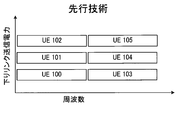
- FIG. 3 is a diagram illustrating another example of allocation of downlink transmission power at the base station to each user apparatus in NOMA.
- the UEs 100 to 102 configure one group of data devices having different transmission powers, and the UEs 103 to 105 configure another group of data devices having different transmission powers.
- a UE with low reception power (for example, UE 103) demodulates a data signal addressed to another UE (for example, UE 104, 105) with high reception power belonging to the group to which the UE itself belongs, and cancels a replica signal as a demodulation result.
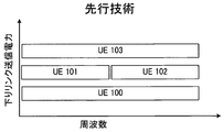
- FIG. 4 is a diagram illustrating another example of allocation of downlink transmission power at the base station to each user apparatus in NOMA.
- the highest transmission power is assigned to the UE 103
- the middle transmission power is assigned to the UEs 101 and 102
- the lowest transmission power is assigned to the UE 100.
- the UEs 101, 102 are assigned the same transmission power, but the UEs 100, 101, 103 constitute one group of data devices with different transmission powers, and the UEs 100, 102, 103 are other data devices with different transmission powers.
- a group is formed.
- the UEs 101 and 102 demodulate the data signal addressed to the UE 103 and cancel the demodulated replica signal.
- the UE 100 demodulates data signals addressed to other UEs (that is, UEs 101 to 103) belonging to both groups to which the UE 100 belongs.
- PDCCH Physical-dedicated-control-channel
- the interference canceller needs to decode PDCCH signals corresponding to other UEs.
- the information elements transmitted by PDCCH are described in section 5.3.3.1 of 3GPP TS 36.212 V11.4.0, and differ depending on the DCI (Downlink Control Information) format.
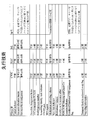
- FIG. 5 shows PDCCH information elements required for typical candidates of interference cancellers used in NOMA.
- CWIC requires more information elements than SLIC and ML.
- a UE provided with an interference canceller needs to know these various information elements of other UEs that are interference sources.
- the PDCCH signal includes a CRC (Cyclic Redundancy Check) bit scrambled by the C-RNTI (Cell-Radio Network Temporary ID) of the destination UE, and is obtained by descrambling the PDCCH signal. If the RNTI matches the UE's own RNTI, the PDCCH signal is a PDCCH signal for the UE. Using the same principle, if the UE knows the C-RNTI of the other UE, the PDCCH signal of the other UE can be descrambled and the control information element included therein can be decoded.
- C-RNTI is simply referred to as RNTI for the sake of simplicity.
- the UE determines the aggregation level corresponding to the PDCCH signal based on the PDCCH signal corresponding to the UE itself, and is equal to or higher than the determined aggregation level.
- the PDCCH signal corresponding to the aggregation level is used for blind decoding for demodulation of a non-orthogonal data signal (interference data signal).
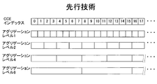
- FIG. 6 shows the aggregation level.
- PDCCH is assigned to REG (resource element group) other than PCFICH (physical control format indicator channel) and PHICH (physical hybrid-ARQ indicator channel).
- REG resource element group
- PCFICH physical control format indicator channel
- PHICH physical hybrid-ARQ indicator channel
- CCE Control Channel Element
- the number of CCEs to which DCI transmitted by PDCCH is assigned varies depending on the aggregation level.
- the aggregation level is 1, 2, 4, or 8. In the following, description will be made using eight CCEs.
- 8 PDCCH signals corresponding to 8 UEs are transmitted by 8 CCEs. That is, 1 PDCCH signal corresponding to 1 UE is transmitted by CCE of index 0, 1 PDCCH signal corresponding to 1 UE is transmitted by CCE of index 1, and 1 UE is supported by CCE of index 2 1 PDCCH signal is transmitted. In this way, one PDCCH signal corresponding to one UE is transmitted in each CCE.
- 4 PDCCH signals corresponding to 4 UEs are transmitted by 8 CCEs. That is, one PDCCH signal corresponding to one UE is transmitted by CCEs with indexes 0 and 1, one PDCCH signal corresponding to one UE is transmitted by CCEs with indexes 2 and 3, and CCEs with indexes 4 and 5 are transmitted. One PDCCH signal corresponding to one UE is transmitted. In this way, one PDCCH signal corresponding to one UE is transmitted by each pair of CCEs.
- 2 PDCCH signals corresponding to 2 UEs are transmitted with 8 CCEs. That is, one PDCCH signal corresponding to one UE is transmitted by CCEs having indexes 0 to 3, one PDCCH signal corresponding to one UE is transmitted by CCEs having indexes 4 to 7, and CCEs having indexes 8 to 11 are transmitted. One PDCCH signal corresponding to one UE is transmitted. As described above, one PDCCH signal corresponding to one UE is transmitted in each set including four CCEs.
- one PDCCH signal corresponding to one UE is transmitted with eight CCEs. That is, one PDCCH signal corresponding to one UE is transmitted by CCEs having indexes 0 to 7, one PDCCH signal corresponding to one UE is transmitted by CCEs having indexes 8 to 15, and CCEs having indexes 16 to 23 are transmitted. One PDCCH signal corresponding to one UE is transmitted. In this way, one PDCCH signal corresponding to one UE is transmitted in each set including eight CCEs.
- the lower the aggregation level the smaller the CCE assigned to one UE (one PDCCH signal), and the higher the aggregation level, the smaller the number of UEs using eight CCEs (the number of PDCCH signals). .
- This is to increase the probability of successful reception of the PDCCH signal by giving a high aggregation level to a UE having low downlink reception quality.
- the aggregation level is set by the base station based on CQI, ACK / NACK, etc. fed back from the UE.
- a low aggregation level is set for a UE with good downlink reception quality
- a high aggregation level is set for a UE with poor downlink reception quality.
- the base station does not notify the UE of the aggregation level and CCE to which the UE's own PDCCH is allocated.
- the CCE can be known, and therefore the aggregation level can also be known.
- there is a limitation in CCE allocation Specifically, if an aggregation level 1 UE is assigned to the index 0 CCE, only another aggregation level 1 UE is assigned to the index 1 CCE, but an aggregation level 1 is assigned to the index 2 CCE.
- another UE of 2 can be assigned, and another UE of aggregation level 1, 2 or 4 can be assigned to the CCE of index 4 (other UEs of aggregation level 8 can be assigned to the CCE of indexes 1 to 7). Absent). If an aggregation level 2 UE is assigned to an index 0 CCE, then only that UE is assigned to an index 1 CCE, and another aggregation level 1 or 2 UE is assigned to an index 2 CCE. In addition, an aggregation level 1, 2, or 4 other UEs can be assigned to the CCE of index 4 (other UEs of aggregation level 8 are not assigned to the CCEs of indexes 1 to 7).
- an aggregation level 4 UE is assigned to a CCE of index 0, only that UE is assigned to a CCE of indexes 1 to 3, and another UE of aggregation level 1, 2 or 4 is assigned to a CCE of index 4 (No other UEs in aggregation level 8 are assigned to CCEs with indexes 1-7). If a UE with aggregation level 8 is assigned to a CCE with index 0, only that UE is assigned to CCEs with subsequent indexes 1 to 7. That is, when the aggregation level is n, the CCE index that is a multiple of n is the CCE start number of the PDCCH signal of the UE at the aggregation level.
- a low aggregation level is set for UEs with good downlink reception quality.
- NOMA low data transmission power is allocated to UEs with good downlink reception quality, and a low aggregation level is set.
- a high data transmission power is assigned to a UE with poor reception quality, and a high aggregation level is set. Therefore, it is assumed that a UE in which a data signal is overlapped with another UE in NOMA is less required to try to decode an aggregation level lower than itself in order to decode a PDCCH addressed to the other UE. Therefore, based on the aggregation level of the UE itself, it is possible to limit the searched space in which another UE's PDCCH signal is searched.
- the aggregation level assigned to the UE itself is 4, it is necessary to cancel the data signal addressed to the UE whose aggregation level is 8, but the data signal addressed to the UE whose aggregation level is 1, 2 or 4 is cancelled. do not have to. Therefore, if the aggregation level assigned to the UE itself is 4, it is necessary to decipher the PDCCH signal of aggregation level 8 (each set consisting of a multiple of 8 and 8 CCEs starting with 0) There is no need to decode PDCCH signals at aggregation levels 1, 2 or 4. That is, each set consisting of one CCE, each set consisting of two CCEs, and each set consisting of four CCEs can be excluded from the PDCCH signal decoding targets.
- the aggregation level assigned to the UE itself is 2, it is necessary to cancel the data signal addressed to the UE whose aggregation level is 4 or 8, but the data signal addressed to the UE whose aggregation level is 1 or 2 is cancelled. do not have to. Therefore, if the aggregation level assigned to the UE itself is 2, it is necessary to decipher the PDCCH signals of aggregation levels 4 and 8 (a set of CCEs whose index starts with a multiple of 4 and 0), but aggregation level 1 Or it is not necessary to decode the PDCCH signal of 2. That is, each set consisting of one CCE and each set consisting of two CCEs can be excluded from the PDCCH signal decoding targets.
- each set of one CCE can be excluded from the PDCCH signal decoding target.
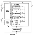
- FIG. 7 is a block diagram showing the configuration of the base station according to the first embodiment of the present invention.
- the base station 1 includes a control unit 30, a radio transmission unit 32, a plurality of transmission antennas 33, a radio reception unit 34, a reception antenna 35, and an inter-base station communication unit 36.
- the radio transmission unit 32 is a transmission circuit for converting an electric signal into a radio wave transmitted from the transmission antenna 33 so that the base station 1 performs radio transmission to each UE.
- the transmission antenna 33 constitutes an adaptive antenna array.
- the radio reception unit 34 is a reception circuit for converting radio waves received from the reception antenna 35 into electric signals so that the base station 1 performs radio reception from each UE.
- the inter-base station communication unit 36 is a communication interface for the base station 1 to communicate with other base stations.
- the control unit 30 includes a CQI report processing unit 38, a control signal generation unit 40, a scheduler 41, a downlink transmission power determination unit 42, and an RRC (radio resource control) signal generation unit 43.
- the control unit 30 is a CPU (central processing unit) that operates according to a computer program.
- the internal elements of the control unit 30 are functional blocks realized by the control unit 30 functioning according to the computer program.
- the control unit 30 processes an uplink data signal transmitted from each UE connected to the base station 1 and received by the radio reception unit 34.
- the CQI report processing unit 38 recognizes the SINR at each UE based on the CQI (channel quality indicator) reported from each UE connected to the base station 1 and received by the radio reception unit 34.
- the control signal generation unit 40 generates a control signal (PDCCH signal) destined for each UE based on the SINR and other parameters in each UE. Based on the SINR and / or other parameters of each UE, the scheduler 41 determines frequency resources and time resources for transmitting downlink data signals each destined for a plurality of UEs connected to the base station 1. decide. Further, the scheduler 41 determines the target UE for the NOMA and further determines the grouping of the NOMA.
- PDCCH signal control signal
- the downlink transmission power determination unit 42 determines the downlink transmission power used for downlink data transmission to each target UE of the NOMA connected to the base station 1 based on the SINR at each UE. That is, the downlink transmission power determination unit 42 assigns one of different downlink transmission powers used for downlink data transmission to each of the UEs according to the reception quality of the plurality of UEs.
- the method for determining the downlink transmission power may be either a known method related to NOMA or a method suitable for NOMA.
- the downlink transmission power determination unit 42 assigns high downlink transmission power to UEs with low reception quality.
- the RRC signal generator 43 generates a signal for RRC signaling (upper layer signaling) (hereinafter referred to as an RRC signal).
- the RRC signal has a period longer than the period of the PDCCH signal (1 subframe (1 ms)). For example, the period may be 100 ms or 1 s.
- the RRC signal generation unit 43 refers to the NOMA grouping determined by the scheduler 41, and uses the identifier information indicating a plurality of RNTIs of all UEs belonging to any of the groups to which the NOMA is applied. Include in RRC signal.
- the control unit 30 supplies a downlink data signal and a PDCCH signal, each of which is addressed to a plurality of UEs connected to the base station 1, to the radio transmission unit 32.
- the radio transmission unit 32 transmits a downlink data signal and a PDCCH signal by the transmission antenna 33.
- the wireless transmission unit 32 sets a plurality of UEs that are the targets of NOMA for each group to which NOMA is applied so that each data signal is transmitted with the downlink transmission power determined by the downlink transmission power determination unit 42.
- a mixed data signal in which a plurality of data signals that are not orthogonal to each other are mixed is transmitted. Therefore, data signals are transmitted with different downlink transmission powers to a plurality of UEs that simultaneously use the same frequency for downlink transmission.
- the wireless transmission unit 32 transmits a plurality of data signals destined for a plurality of UEs in a certain group with different downlink transmission powers without being orthogonal to each other, and a plurality of data signals destined for a plurality of UEs in another group
- the mixed data signal is transmitted in a format that is transmitted with different downlink transmission powers that are not orthogonal to each other.
- the downlink transmission power allocation may be as in the example shown in FIG. 3 or the example shown in FIG.
- the radio transmission unit 32 may transmit a plurality of PDCCH signals to a plurality of UEs, and each UE may decode a data signal destined for the UE itself using a PDCCH signal corresponding to the UE itself. It can be so.
- the radio transmission unit 32 transmits each PDCCH signal in a format scrambled with the RNTI of the UE corresponding to the PDCCH signal.
- the radio transmission unit 32 transmits an RRC signal including identifier information indicating a plurality of RNTIs of all UEs belonging to any of the groups to which NOMA is applied, in a cycle longer than the cycle of the PDCCH signal.
- the identifier information indicates RNTIs of UEs of all groups to which NOMA is applied at the base station. Therefore, each UE connected to this base station receives an RRC signal including such identifier information.
- a UE whose downlink transmission power belonging to each group is not highest refers to the identifier information, and another UE that is a destination of an interference data signal to which higher transmission power is assigned than the UE itself belonging to the group to which the UE itself belongs
- the PDCCH signal for the UE can be descrambled, and the interference data signal can be demodulated and canceled using the control information element included in the PDCCH signal for the other UE.
- the radio transmission unit 32 does not transmit information indicating the radio resource (CCE) used for transmission of the PDCCH signal of the UE and other UEs to each UE.
- CCE radio resource
- the RRC signal includes identifier information indicating a plurality of RNTIs of all UEs belonging to any of the groups to which NOMA is applied, for example, in the case of allocation of downlink transmission power illustrated in FIG. 3, all of the RRC signals illustrated in FIG.
- the UE knows the RNTI of all UEs shown in FIG. 3 regardless of the group to which the UE belongs.
- UE 101 decodes the PDCCH signal of UE 102 using RNTI of UE 102, and demodulates the data signal addressed to UE 102 using the information element included in the PDCCH signal. can do.
- the UE 104 can decode the PDCCH signal of the UE 105 using the RNTI of the UE 105 and demodulate the data signal addressed to the UE 105 using the information element included in the PDCCH signal.
- the UE 100 can decode the PDCCH signal of the UE 102 using the RNTI of the UE 102, demodulate the data signal addressed to the UE 102 using the information element included in the PDCCH signal, and further use the RNTI of the UE 101 to demodulate the PDCCH of the UE 101.
- the signal can be decoded and the data signal addressed to UE 101 can be demodulated using the information element included in the PDCCH signal.
- the UE 103 can decode the UE 105 PDCCH signal using the UE 105 RNTI, demodulate the data signal addressed to the UE 105 using the information elements included in the PDCCH signal, and use the UE 104 RNTI to demodulate the UE 104 PDCCH.
- the signal can be decoded and the data signal addressed to the UE 104 can be demodulated using the information element included in the PDCCH signal.
- UE 101 and UE 102 decode the UE 103 PDCCH signal using the UE 103 RNTI, and use the information element included in the PDCCH signal to transmit the data signal addressed to UE 103. Can be demodulated.
- the UE 100 can decode the UE 103 PDCCH signal using the UE 103 RNTI, demodulate the data signal addressed to the UE 103 using the information element included in the PDCCH signal, and can further use the UE 101 RNTI to demodulate the UE 101 PDCCH.
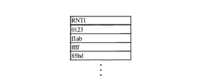
- FIG. 8 is a table showing an example of identifier information indicating RNTI.
- the identifier information may be in the form of a list.
- Each RNTI has a length of 16 bits, but the bit length of the RNTI will depend on the system.
- This list may be notified to UEs belonging to all groups semi-statically (in a semi-static manner) by upper layer signaling (RRC signaling).
- RRC signaling upper layer signaling
- the list may be compressed using existing data compression techniques. The compression can suppress an increase in the amount of information transmitted by higher layer signaling.
- FIG. 9 is a block diagram showing a configuration of UE 10 according to the first embodiment.
- the above-described UE (UE 100 or the like) has the same configuration as UE 10.
- the UE 10 includes a control unit 50, a radio transmission unit 52, a transmission antenna 53, a radio reception unit 54, and a plurality of reception antennas 55.
- the wireless transmission unit 52 is a transmission circuit for converting an electrical signal into a radio wave transmitted from the transmission antenna 53 so that the UE 10 performs wireless transmission to the serving base station.
- the radio reception unit 54 is a reception circuit for converting radio waves received from the reception antenna 55 into electrical signals so that the UE 10 performs radio reception from the serving base station.
- the receiving antenna 55 constitutes an adaptive antenna array.
- the control unit 50 is a CPU that operates according to a computer program.
- the control unit 50 includes a reception quality measurement unit 60, a CQI report unit 61, a first PDCCH descrambling unit (first descrambling unit) 62, a recognition unit 64, a second PDCCH descrambling unit (second descrambling unit).
- Unit) 66 a non-orthogonal signal demodulator 68, a non-orthogonal signal cancel unit 70, a desired data signal demodulation / decoding unit (desired data signal decoding unit) 72, and an aggregation level determination unit 74.
- These internal elements of the control unit 50 are functional blocks realized by the control unit 50 functioning according to the computer program.
- the control unit 50 supplies the uplink data signal to the radio transmission unit 52, and the radio transmission unit 52 transmits the uplink data signal to the serving base station via the transmission antenna 53.
- the reception quality measurement unit 60 measures the SINR of the radio signal received by the radio reception unit 54.
- the CQI reporting unit 61 generates a CQI based on the SINR, and supplies the CQI to the wireless transmission unit 52.
- the radio transmission unit 52 transmits the CQI to the serving base station using the control channel.
- the radio reception unit 54 includes, from the serving base station, a mixed data signal including a plurality of non-orthogonal data signals having different powers each destined for a plurality of UEs, and a plurality of PDCCH signals corresponding to the plurality of UEs.
- the RRC signal having the identifier information is received.
- the first PDCCH descrambling unit 62 descrambles the PDCCH signal corresponding to the UE 10 itself using the RNTI of the UE 10 itself.
- the recognition unit 64 analyzes the RRC signal and recognizes the RNTI of all other UEs included in the identifier information of the RRC signal.
- the second PDCCH descrambling unit 66 descrambles the PDCCH signal corresponding to the other UE using the RNTI of the other UE recognized by the recognition unit 64.
- the non-orthogonal signal demodulation unit 68 demodulates the non-orthogonal data signal using a control information element included in the PDCCH signal corresponding to another UE descrambled by the second PDCCH descrambling unit 66.
- the non-orthogonal signal canceling unit 70 cancels the replica signal corresponding to the non-orthogonal data signal demodulated by the non-orthogonal signal demodulating unit 68 from the mixed data signal.
- second PDCCH descrambling section 66, non-orthogonal signal demodulating section 68 and non-orthogonal signal canceling section 70 constitute an interference canceller for this UE.
- the interference canceller may be SLIC, CWIC, or ML. If the interference canceller is a CWIC, the non-orthogonal signal demodulator 68 performs not only demodulation but also decoding of the non-orthogonal data signal.
- the desired data signal demodulating / decoding unit 72 uses the PDCCH signal corresponding to the UE itself descrambled by the first PDCCH descrambling unit 62 to generate a desired data signal from the signal output from the non-orthogonal signal canceling unit 70. Decrypt.
- the aggregation level determination unit 74 determines the CCE of the PDCCH signal corresponding to the UE itself, and determines the aggregation level corresponding to the PDCCH signal based on the CCE.
- the second PDCCH descrambling unit 66 tries to descramble a plurality of PDCCH signals corresponding to an aggregation level higher than the aggregation level corresponding to the UE itself using the RNTI of another UE.
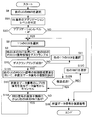
- FIG. 10 is a flowchart showing a process for specifying the PDCCH signal of the UE 10 itself, which is executed by the UE 10.
- the first PDCCH descrambling unit 62 selects one candidate of a plurality of PDCCH signals (a plurality of PDCCH signals including the PDCCH signal of the UE 10) transmitted from the base station in step S1, and in step S2, the UE 10 itself Using RNTI, descrambling of the PDCCH signal corresponding to the UE 10 itself is tried.
- the PDCCH signal includes CRC bits scrambled by RNTI. If the RNTI obtained by descrambling the selected PDCCH signal candidate matches the RNTI of the UE itself, the PDCCH signal candidate is It is a PDCCH signal for the UE.
- the first PDCCH descrambling unit 62 selects another PDCCH signal candidate (step S5), and descrambles the PDCCH signal candidate (step S2).
- step S4 When it is determined in step S4 that the first PDCCH descrambling unit 62 has succeeded in descrambling the UE's own PDCCH signal (when the RNTI obtained by descrambling the PDCCH signal candidate matches the UE's own RNTI ),
- the control unit 50 stores a control information element included in the PDCCH signal and required for demodulation and decoding of the desired data signal in a storage device (not shown) (step S5A).
- FIG. 11 is a flowchart showing processing for performing demodulation and decoding of a desired data signal executed by the UE 10. This process is executed in the cycle of the PDCCH signal. Before executing this process, the UE 10 has received a long-cycle RRC signal from the base station, and the recognition unit 64 recognizes the RNTIs of all other UEs included in the identifier information.
- the second PDCCH descrambling unit 66 selects one RNTI of another UE recognized by the recognition unit 64 (step S6).
- the aggregation level determination unit 74 determines the CCE of the PDCCH signal corresponding to the UE itself, and determines the aggregation level corresponding to the PDCCH signal based on the CCE.
- the aggregation level determination unit 74 determines CCE groups corresponding to PDCCH signal candidates of other UEs based on the aggregation level corresponding to the UE itself. As described above, for example, if the aggregation level assigned to the UE itself is 2, there is no need to decode the PDCCH signal of aggregation level 1 or 2, so each set of one CCE and two CCEs Each set can be excluded from the PDCCH signal decoding targets. In this case, in order to decode the PDCCH signals of aggregation levels 4 and 8, the aggregation level determination unit 74 sets the CCE set starting with a multiple of 4 and 0 as the CCE group corresponding to the PDCCH signal candidates of other UEs. judge.
- step S8C the second PDCCH descrambling unit 66 selects one CCE from the CCE group determined in step S8B, and in step S9, using the RNTI of another UE, the PDCCH signal in the CCE Try candidate descrambling. In this way, the second PDCCH descrambling unit 66 tries to descramble a plurality of PDCCH signal candidates corresponding to an aggregation level higher than the aggregation level corresponding to the UE itself.
- the PDCCH signal candidate of another UE is a PDCCH signal for the other UE. If it is determined in step S10 that the second PDCCH descrambling unit 66 has not succeeded in descrambling the PDCCH signal of another UE (other than the RNTI obtained by descrambling the PDCCH signal candidate is selected in step S6) 2), the second PDCCH descrambling unit 66 selects another CCE from the CCE group determined in step S8B (step S11A), and descrambles other PDCCH signal candidates. (Step S9).
- the scrambled PDCCH signal is not necessarily a PDCCH signal for other UEs belonging to the group to which the UE 10 itself belongs.
- the RRC signal since the RRC signal includes identifier information indicating a plurality of RNTIs of all UEs belonging to any of the groups to which NOMA is applied, the RNTIs of other UEs known by the UE are the data addressed to the UE. This is because it includes not only the RNTI of the destination UE of the non-orthogonal data signal superimposed on the signal but also the RNTI of UEs belonging to other groups.
- step S12A the non-orthogonal signal demodulation unit 68 attempts to demodulate the non-orthogonal data signal using the control information element in the PDCCH signal for another UE, and whether or not the demodulation is successful in step S12B. to decide. If the demodulation of the non-orthogonal data signal is successful, in step S13, the non-orthogonal signal canceling unit 70 cancels the replica signal corresponding to the non-orthogonal data signal from the mixed data signal.
- the PDCCH signal used for the demodulation is a PDCCH signal of another group of UEs, and does not correspond to the interference data signal that overlaps the desired data signal addressed to the UE 10. Therefore, the process proceeds to step S12C.
- the second PDCCH descrambling unit 66 selects another RNTI recognized by the recognition unit 64.
- the second descrambling unit 66 uses another RNTI indicated by the identifier information of the RRC signal from the base station and recognized by the recognition unit 64, and uses one PDCCH signal as a plurality of PDCCH signal candidates corresponding to a plurality of UEs.
- Candidate descrambling is attempted (steps S8C and S9).
- step S14A When the RNTI of another UE is further included in the identifier information of the RRC signal from the base station, the determination in step S14A is affirmative, and the process returns to step S8C.
- the desired data signal addressed to the UE 10 itself will interfere with other higher power UEs belonging to the group to which the UE 10 belongs. Data signals are not overlapping.
- the desired data signal demodulation / decoding unit 72 uses the PDCCH signal corresponding to the UE itself descrambled by the first PDCCH descrambling unit 62, from the signal output from the non-orthogonal signal cancellation unit 70. The desired data signal is decoded (step S16).
- the second PDCCH descrambling unit 66 may try to descramble a plurality of PDCCH signals corresponding to an aggregation level equal to or higher than the aggregation level corresponding to the UE itself using RNTI of other UEs. For example, if the aggregation level assigned to the UE itself is 2, in addition to the aggregation levels 4 and 8, the aggregation level 2 PDCCH signal may be decoded.
- the aggregation level determination unit 74 determines that the index is 2 A set of CCEs starting with a multiple of 0 and 0 is determined as a CCE group corresponding to PDCCH signal candidates of other UEs. Thereby, the second PDCCH descrambling unit 66 tries to descramble a plurality of PDCCH signal candidates corresponding to aggregation levels 2, 4 and 8 of aggregation level 2 or higher corresponding to the UE itself.
- the aggregation level determination unit 74 sets a set of CCEs starting with a multiple of 4 and 0 to another UE. It may be determined as a CCE group corresponding to the PDCCH signal candidate. In this case, CCEs at aggregation levels 4 and 8 are selected in step S8C, and in step S9, the second PDCCH descrambling unit 66 uses the RNTI of another UE and PDCCH signal candidates of other UEs in that CCE. Try to descramble.
- the base station transmits identifier information indicating a plurality of RNTIs of all UEs belonging to any of the groups to which NOMA is applied in a period longer than the transmission period of the PDCCH signal.
- identifier information indicating a plurality of RNTIs of all UEs belonging to any of the groups to which NOMA is applied in a period longer than the transmission period of the PDCCH signal.
- a UE whose downlink transmission power belonging to each group is not the highest uses the RNTI indicated in the identifier information, and other UEs that are destinations of data signals having higher transmission power than that UE belonging to the group to which the UE belongs. Therefore, the PDCCH signal can be descrambled, the interference data signal addressed to another UE can be demodulated, and the replica signal corresponding to the interference data signal can be canceled from the mixed data signal.
- the PDCCH signal is not used for transmitting the identifier information, it is possible to suppress an increase in the amount of information for the interference canceller transmitted with the PDCCH signal. Since the transmission period of the identifier information is longer than the transmission period of the PDCCH signal, an increase in traffic can be suppressed.
- identifier information indicating a plurality of RNTIs of all UEs belonging to any of the groups to which NOMA is applied is transmitted to each UE connected to the base station. Therefore, the processing load of the base station is lighter than that in which the base station determines which UE is notified of which RNTI according to NOMA grouping.
- a low aggregation level is set for UEs with good downlink reception quality
- a high aggregation level is set for UEs with poor downlink reception quality.
- NOMA a low transmission power is assigned to a UE with good downlink reception quality, and the UE cancels a data signal addressed to a UE with a poor reception quality and a high transmission power. Therefore, a UE for which a high aggregation level is set is a UE having poor downlink reception quality and assigned a high transmission power, and such a UE is a desired data signal (high power) destined for the UE itself. Even if an interference data signal (low power) destined for another UE is overlapped by NOMA, the desired data signal can be decoded without canceling the data signal destined for the other UE.
- the UE according to the second embodiment determines an aggregation level corresponding to the PDCCH signal based on the PDCCH signal corresponding to the UE itself, and a value with an aggregation level corresponding to the UE itself (for example, If higher than 2 or 4), the desired data signal is decoded without canceling the data signal destined for another UE. For this reason, when the aggregation level corresponding to the UE itself is higher than a certain value (for example, 2 or 4), the PDCCH signal of the other UE is not decoded and the data signal addressed to the other UE is not demodulated. .
- a certain value for example, 2 or 4
- the block diagram of the UE according to the second embodiment may be the same as FIG. However, when the aggregation level corresponding to the PDCCH signal determined by the aggregation level determination unit 74 is higher than a certain value, the second PDCCH descrambling unit 66, the non-orthogonal signal demodulation unit 68, and the non-orthogonal signal cancellation unit 70 Without operation, the desired data signal demodulation and decoding unit 72 decodes the mixed data signal as a desired data signal.
- a process for demodulating and decoding a desired data signal executed by the UE 10 according to the second embodiment will be described with reference to the flowchart of FIG. This process is similar to the process shown in FIG. 11, and the same reference numerals are used to indicate the same steps as those shown in FIG. 11, and such steps will not be described in detail.
- the process (FIG. 10) for specifying the UE10's own PDCCH signal executed by the UE10 is also executed in this embodiment.
- step S8A the aggregation level determination unit 74 determines the CCE of the PDCCH signal corresponding to the UE itself, and based on the CCE, the aggregation corresponding to the PDCCH signal. Determine the level.
- step S8D the aggregation level determination unit 74 determines whether the aggregation level corresponding to the PDCCH signal is lower than a certain threshold (for example, 4). If the determination in step S8D is negative (that is, if the aggregation level corresponding to the PDCCH signal is 4 or 8), the second PDCCH descrambling unit 66, the non-orthogonal signal demodulating unit 68, and the non-orthogonal Without the signal canceling unit 70 operating, the desired data signal demodulating / decoding unit 72 demodulates and decodes the mixed data signal as a desired data signal of the UE 10 itself (step S16). That is, since the UE 10 itself is assigned high transmission power by the NOMA, the UE 10 demodulates and decodes the received data signal as the desired data signal of the UE itself without operating the interference canceller.
- a certain threshold for example, 4
- step S8D If the determination in step S8D is affirmative (that is, if the aggregation level corresponding to the PDCCH signal is 1 or 2), the second PDCCH descrambling unit 66 selects one CCE in step S8. In step S9, an attempt is made to descramble the PDCCH signal candidate in the CCE using the RNTI of another UE.
- the process for demodulating or canceling the data signal of another UE can be omitted, and the processing burden on the UE can be reduced. it can.
- the third embodiment is a modification of the first embodiment, and the radio transmission unit 32 of the base station (FIG. 7) transmits information indicating the RNTIs of a plurality of UEs targeted for NOMA using an RRC signal. Instead, the RNTI of another UE that is the destination of the canceled data signal is included in the PDCCH signal destined for the UE that should cancel the interference by NOMA. That is, the radio transmission unit 32 adds the mixed data signal to the PDCCH signal for the first UE that is the destination of the first data signal whose downlink transmission power is not the highest determined by the downlink transmission power determination unit 42.
- the wireless transmission unit 32 notifies the UE with low power multiplexed by the NOMA of the RNTI of a UE that belongs to the same group as the UE and has higher power than that UE.
- the radio transmission unit 32 does not transmit information indicating the radio resource used for transmission of the PDCCH signal for the second UE to the first UE.
- the radio transmission unit 32 does not include the RNTI of another UE in the PDCCH signal addressed to the UEs 102 and 105.
- the radio transmission unit 32 includes the RNTI of the UE 102 in the PDCCH signal addressed to the UE 101, and includes the RNTI of the UE 101 in the PDCCH signal addressed to the UE 100.
- the radio transmission unit 32 includes the RNTI of the UE 105 in the PDCCH signal addressed to the UE 104, and includes the RNTI of the UE 104 in the PDCCH signal addressed to the UE 103.
- the UE 101 can decode the PDCCH signal of the UE 102 using the RNTI of the UE 102 and demodulate the data signal addressed to the UE 102 using the information element included in the PDCCH signal.
- the UE 104 can decode the PDCCH signal of the UE 105 using the RNTI of the UE 105 and demodulate the data signal addressed to the UE 105 using the information element included in the PDCCH signal.
- the UE 100 decodes the PDCCH signal of the UE 101 using the RNTI of the UE 101, further decodes the PDCCH signal of the UE 102 using the RNTI of the UE 102 included therein, and uses the information element included in the PDCCH signal to address the UE 102
- the data signal can be demodulated (the data signal addressed to UE 101 can then be demodulated using the PDCCH signal of UE 101).
- the UE 103 decodes the PDCCH signal of the UE 104 using the RNTI of the UE 104, further decodes the PDCCH signal of the UE 105 using the RNTI of the UE 105 included therein, and uses the information element included in the PDCCH signal to address the UE 105
- the data signal can be demodulated (the data signal destined for the UE 104 can then be demodulated using the PDCCH signal of the UE 104).
- the radio transmission unit 32 does not include the RNTI of another UE in the PDCCH signal addressed to the UE 103.
- the radio transmission unit 32 includes the RNTI of the UE 103 in the PDCCH signal addressed to the UE 101, and includes the RNTI of the UE 103 in the PDCCH signal addressed to the UE 102.
- the radio transmission unit 32 includes the RNTI of UE 101 and the RNTI of UE 102 in the PDCCH signal addressed to UE 100.
- UE101 and UE102 can demodulate the PDCCH signal of UE103 using RNTI of UE103, and can demodulate the data signal addressed to UE103 using the information element contained in the PDCCH signal.
- UE 100 decodes UE 101's PDCCH signal using UE 101's RNTI, UE 102's PDCCH signal using UE 102's RNTI, and UE 103's PDCCH signal using UE 103's RNTI included in those PDCCH signals.
- the data signal destined for UE103 can be demodulated using the information elements included in the PDCCH signal (after that, the data signal destined for UE101 is demodulated using the PDCCH signal of UE101, and the PDCCH signal of UE102 is used.
- the data signal addressed to the UE 102 can be demodulated).
- FIG. 13 is a block diagram showing a configuration of the UE 10 according to the third embodiment.
- the control unit 50 of the UE 10 includes a recognition unit 164.
- the recognition unit 164 is a functional block realized by the control unit 50 functioning according to the computer program.
- the first PDCCH descrambling unit 62 descrambles the PDCCH signal corresponding to the UE 10 itself using the RNTI of the UE 10 itself.
- the recognizing unit 164 mixes the mixed data signal with the desired data signal destined for the UE 10 itself from the information included in the PDCCH signal corresponding to the UE 10 itself descrambled by the first PDCCH descrambling unit 62. Recognize the RNTI of at least one other UE that is the destination of at least one non-orthogonal data signal.
- the second PDCCH descrambling unit 66 descrambles the PDCCH signal corresponding to the other UE using the RNTI of the other UE recognized by the recognition unit 164.
- Second PDCCH descrambling section 66, non-orthogonal signal demodulating section 68 and non-orthogonal signal canceling section 70 constitute an interference canceller for this UE.
- the interference canceller may be SLIC, CWIC, or ML. If the interference canceller is a CWIC, the non-orthogonal signal demodulator 68 performs not only demodulation but also decoding of the non-orthogonal data signal.
- FIG. 14 is a flowchart showing processing executed by the UE 10 of FIG. 14, the same reference numerals are used to indicate the same steps as the processes shown in FIGS. 10 and 11, and such steps will not be described in detail.
- step S6A the recognizing unit 164 determines whether the RNTI of another UE is included in the information included in the PDCCH signal corresponding to the descrambled UE 10 itself.
- the second PDCCH descrambling unit 66, the non-orthogonal signal demodulating unit 68, and the non-orthogonal signal canceling unit 70 do not operate, and the desired data signal
- the demodulation / decoding unit 72 demodulates and decodes the mixed data signal as a desired data signal of the UE 10 itself (step S7). That is, a UE (for example, UE 102 or UE 105 in the example of FIG. 3) to which the highest transmission power is allocated in each group of NOMA demodulates the received data signal as a desired data signal of the UE itself without operating an interference canceller. And decrypt.
- the second PDCCH descrambling unit 66 determines the CCE of the PDCCH signal corresponding to the UE itself in Step S8A. Based on the CCE, the aggregation level corresponding to the PDCCH signal is determined. In step S8B, the aggregation level determination unit 74 determines a CCE group corresponding to a PDCCH signal candidate of another UE based on the aggregation level corresponding to the UE itself.
- step S8C the second PDCCH descrambling unit 66 selects one CCE from the CCE group determined in step S8B, and in step S9, using the RNTI of another UE, the PDCCH signal in the CCE Try candidate descrambling.
- the PDCCH signal candidate is a PDCCH signal for the other UE.
- the second PDCCH descrambling unit 66 selects another one of the CCE groups determined in step S8B (step S11A), and deselects other PDCCH signal candidates. It is scrambled (step S9).
- the second PDCCH descrambling unit 66 determines in step S10 that the descrambling of the PDCCH signal of another UE has succeeded (the RNTI obtained by descrambling the PDCCH signal candidate is the other RNTI recognized in step S6A).
- the PDCCH signal obtained by descrambling is a PDCCH signal corresponding to another UE to which higher power belonging to the group to which this UE 10 belongs is assigned to the other UE.
- a control information element (see FIG. 5) necessary for demodulating a data signal (non-orthogonal data signal) is included. Therefore, in step S12, the non-orthogonal signal demodulator 68 demodulates the non-orthogonal data signal using these control information elements.
- the non-orthogonal signal cancellation unit 70 cancels the replica signal corresponding to the non-orthogonal data signal from the mixed data signal.
- step S14 When the RNTI of another UE is further included in the PDCCH signal of the UE 10 itself, the determination in step S14 is affirmative, and the process returns to step S8C.
- the determination in step S15 is affirmative, and the process returns to step S8C.
- the desired data signal addressed to the UE 10 itself includes other higher power than the group to which the UE 10 belongs. This is a state in which interference data signals addressed to UEs do not overlap.
- the desired data signal demodulation / decoding unit 72 uses the PDCCH signal corresponding to the UE itself descrambled by the first PDCCH descrambling unit 62, from the signal output from the non-orthogonal signal cancellation unit 70.
- the desired data signal is decoded (step S16).
- the UE 101 in FIG. 3 makes a negative determination in step S14 and a determination in step S15, and demodulates the data signal addressed to the UE 101.
- the UE 101 in FIG. 3 cancels the data signal addressed to UE102, and then the determination in step S15 is affirmative, further cancels the data signal addressed to UE101 and demodulates the data signal addressed to UE100.
- UE 100 in FIG. 4 cancels the data signal addressed to UE 102 after the determination in step S14 is affirmative, and after the determination in step S14 becomes negative, Demodulate the data signal addressed to UE100.
- the second PDCCH descrambling unit 66 may select a CCE corresponding to an aggregation level higher than the aggregation level corresponding to the UE itself, or to an aggregation level equal to or higher than the aggregation level corresponding to the UE itself.
- a corresponding CCE may be selected. For example, if the aggregation level assigned to the UE itself is 2, the PDCCH signals of aggregation levels 4 and 8 may be decoded.
- the aggregation level determination unit 74 starts with an index that is a multiple of 4 and 0.
- a set of CCEs to be determined is determined as a CCE group corresponding to PDCCH signal candidates of other UEs.
- the second PDCCH descrambling unit 66 tries to descramble a plurality of PDCCH signal candidates corresponding to aggregation levels 4 and 8 higher than the aggregation level 2 corresponding to the UE itself.
- the PDCCH signal at aggregation level 2 may be decoded in addition to the aggregation levels 4 and 8, and the aggregation level determination unit 74 determines that the index is 2 in step S8B.
- a set of CCEs starting with a multiple of 0 and 0 is determined as a CCE group corresponding to PDCCH signal candidates of other UEs.
- the second PDCCH descrambling unit 66 tries to descramble a plurality of PDCCH signal candidates corresponding to aggregation levels 2, 4 and 8 of aggregation level 2 or higher corresponding to the UE itself.
- step S8B the aggregation level determination unit 74 sets a set of CCEs starting with a multiple of 4 and 0 to another UE. It may be determined as a CCE group corresponding to the PDCCH signal candidate.
- CCEs at aggregation levels 4 and 8 are selected in step S8C, and in step S9, the second PDCCH descrambling unit 66 attempts to descramble the PDCCH signal candidate of that CCE using the RNTI of another UE. To do.
- step S15 If the determination in step S15 is affirmative (if the RNTI of another UE is further included in the PDCCH signal of another UE determined to have been successfully descrambled in step S10), the process proceeds to step S8C. Return. Accordingly, in step S8C, the second PDCCH descrambling unit 66 selects one CCE from the CCE group determined in step S8B. However, if the PDCCH signal of another UE is successfully decoded in step S10, its CCE can be known, so that the aggregation level of the other UE can also be known. Therefore, if the determination in step S15 is affirmative, the search level for searching for another PDCCH signal of another UE may be further limited by determining the aggregation level of the other UE and determining the CCE based on the determination. Good.
- the PDCCH signal for the first UE that is the destination of the first data signal whose downlink transmission power is not the highest, the first data in the mixed data signal Since the RNTI (16 bits) of at least one second UE that is the destination of at least one second data signal mixed with the signal is included, the first UE uses the RNTI of the second UE.
- the PDCCH signal for the second UE can be descrambled, the second data signal can be demodulated, and the replica signal corresponding to the second data signal can be canceled from the mixed data signal.
- the information indicating the radio resource used for transmitting the PDCCH signal for the second UE is not transmitted to the first UE, the information amount for the interference canceller transmitted by the PDCCH signal is increased. Can be suppressed. In this way, an increase in traffic can be suppressed.
- the UE recognizes the RNTI of at least one other UE from information included in the PDCCH signal corresponding to the UE 10 itself, and uses one of a plurality of PDCCH signals using the RNTI of the other UE.
- the non-orthogonal data signal is demodulated and a replica signal corresponding to the non-orthogonal data signal is canceled from the mixed data signal.
- the UE decodes the PDCCH signal of the other UE by blind decoding and demodulates the non-orthogonal data signal without knowing the radio resources used to transmit the PDCCH signal for the other UE.
- the replica signal corresponding to the non-orthogonal data signal can be canceled from the mixed data signal. Therefore, this UE contributes to suppression of expansion of the information amount for the interference canceller transmitted with the PDCCH signal.
- the radio transmission unit 32 of the base station is determined by the downlink transmission power determination unit 42.
- the radio transmission unit 32 of the base station is determined by the downlink transmission power determination unit 42.
- the wireless transmission unit 32 notifies the RNTI of a UE that belongs to the same group as the UE and has a higher power than the UE to the UE that has a low power multiplexed by the NOMA.
- the RNTI of UEs belonging to other groups is not notified.
- And UE which concerns on this embodiment is at least 1 which is the destination of the non-orthogonal data signal mixed with the desired data signal destined for the UE 10 itself to the mixed data signal from the PDCCH signal corresponding to the UE 10 itself Recognize RNTI of other UEs. That is, the UE recognizes the RNTI of another UE belonging to the same group as the group to which the UE 10 itself belongs.
- the descrambled PDCCH signal is a PDCCH signal for another UE belonging to the same group as the group to which the UE 10 itself belongs, and corresponds to a non-orthogonal data signal. For this reason, when descrambling is successful, the non-orthogonal data signal can be demodulated (step S12), which reduces the processing load on the UE.
- the UE according to the fourth embodiment determines an aggregation level corresponding to the PDCCH signal based on the PDCCH signal corresponding to the UE itself, and a value having an aggregation level corresponding to the UE itself (for example, 2 or 2). 4) If higher, decode the desired data signal without canceling the data signal destined for another UE. For this reason, when the aggregation level corresponding to the UE itself is higher than a certain value (for example, 2 or 4), the PDCCH signal of the other UE is not decoded and the data signal addressed to the other UE is not demodulated. .
- a certain value for example, 2 or 4
- the block diagram of the UE according to the fourth embodiment may be the same as FIG. However, when the aggregation level corresponding to the PDCCH signal determined by the aggregation level determination unit 74 is higher than a certain value, the second PDCCH descrambling unit 66, the non-orthogonal signal demodulation unit 68, and the non-orthogonal signal cancellation unit 70 Without operation, the desired data signal demodulation and decoding unit 72 decodes the mixed data signal as a desired data signal.
- a process executed by the UE 10 according to the fourth embodiment will be described with reference to the flowchart of FIG. This process is similar to the process shown in FIG. 14, and the same reference numerals are used to indicate the same steps as those shown in FIG. 14, and such steps will not be described in detail.
- step S8A the aggregation level determination unit 74 determines whether the UE itself The CCE of the corresponding PDCCH signal is determined, and the aggregation level corresponding to the PDCCH signal is determined based on the CCE.
- step S8D the aggregation level determination unit 74 determines whether the aggregation level corresponding to the PDCCH signal is lower than a certain threshold (for example, 4). If the determination in step S8D is negative (that is, if the aggregation level corresponding to the PDCCH signal is 4 or 8), the second PDCCH descrambling unit 66, the non-orthogonal signal demodulating unit 68, and the non-orthogonal Without the signal cancellation unit 70 operating, the desired data signal demodulation and decoding unit 72 demodulates and decodes the mixed data signal as the desired data signal of the UE 10 itself (step S7). That is, since the UE 10 itself is assigned high transmission power by the NOMA, the UE 10 demodulates and decodes the received data signal as the desired data signal of the UE itself without operating the interference canceller.
- a certain threshold for example, 4
- step S8D If the determination in step S8D is affirmative (that is, if the aggregation level corresponding to the PDCCH signal is 1 or 2), the second PDCCH descrambling unit 66 selects one CCE in step S8. In step S9, an attempt is made to descramble the PDCCH signal candidate in the CCE using the RNTI of another UE.
- the process for demodulating or canceling the data signal of another UE can be omitted, and the processing burden on the UE can be reduced. it can.
- the PDCCH signal is used to notify the UE of the RNTI of the interference UE multiplexed by the NOMA.
- the length of the RNTI is 16 bits, and the period of the PDCCH signal is 1 subframe (1 ms).
- the amount of information that can be transmitted by the PDCCH signal is limited, and the amount of information should be suppressed.
- the base station has a period longer than the transmission period of the PDCCH signal, and a plurality of RNTIs of a plurality of UEs that are destinations of a plurality of data signals that are not orthogonal to each other, and RNTI A list of one-to-one correspondence with a plurality of indexes having a small length is notified to a plurality of UEs that are the target of NOMA, and the PDCCH signal of the UE that is the target of NOMA has high power belonging to the group to which the UE belongs. Include indexes corresponding to other UEs to which is assigned.
- FIG. 16 shows an example of a list used in the fifth embodiment.
- Each RNTI is associated with an index one to one.
- the RNTI has a length of 16 bits, whereas the index has a smaller length.
- This list may include the RNTI of all groups of UEs to which the NOMA applies at the base station.
- This list may be notified semi-statically (to Semi-static) to UEs that do not have the highest transmission power of all groups by higher layer signaling (RRC (Radio Resource Control) signaling).
- RRC Radio Resource Control
- the notification cycle may be 100 ms or 1 s.
- the radio transmission unit 32 (see FIG. 7) of the base station transmits at least one second UE to the PDCCH signal of the first UE (UE having the lowest downlink transmission power targeted by NOMA) transmitted at a period of 1 ms.
- An index corresponding to (UE having higher downlink transmission power than belonging to the group to which the first UE belongs) is included.
- the index has a length smaller than that of the RNTI, it is possible to further suppress an increase in the amount of information for the interference canceller transmitted with the PDCCH signal.
- the list may be compressed using existing data compression techniques. The compression can also suppress an increase in the amount of information transmitted by higher layer signaling.
- the radio reception unit 54 (see FIG. 13) of the UE 10 has a plurality of UEs that are destinations of a plurality of data signals that are not orthogonal to each other in a cycle (for example, 100 ms or 1 s) longer than the transmission cycle (1 ms) of the PDCCH signal.
- Information indicating a list in which the RNTI and a plurality of indexes having a length smaller than the RNTI are associated with each other is received from the base station.
- the radio reception unit 54 of the UE 10 whose downlink transmission power targeted for NOMA is not the highest receives the PDCCH signal of the UE itself including an index corresponding to at least one other UE.
- step S8D in FIG. 12 may be inserted between step S8A and step S8B in FIG. 11 by combining the first embodiment and the second embodiment.
- the third embodiment and the fourth embodiment may be combined, and the determination in step S8D in FIG. 15 may be inserted between step S8A and step S8B in FIG.
- the base station notifies the UE of identifier information indicating a plurality of RNTIs using an RRC signal.
- the base station includes information representing a plurality of RNTIs or RNTIs of a plurality of UEs targeted for NOMA in a PDCCH signal corresponding to each UE targeted for NOMA.
- the RNTI may be transmitted to the UE by other means.
- each function executed by the CPU may be executed by hardware instead of the CPU, or executed by a programmable logic device such as FPGA (Field Programmable Gate Array) or DSP (Digital Signal Processor). Also good.
- FPGA Field Programmable Gate Array
- DSP Digital Signal Processor
- first PDCCH descrambling unit first descrambling unit
- 64 recognition unit 66
- second PDCCH descrambling unit second descrambling unit
Landscapes
- Engineering & Computer Science (AREA)
- Signal Processing (AREA)
- Computer Networks & Wireless Communication (AREA)
- Quality & Reliability (AREA)
- Mobile Radio Communication Systems (AREA)
Abstract
Description
・Symbol-level Interference Canceller (SLIC)
これは、シンボルレベルで(すなわちRE(リソースエレメント)ごと)に干渉信号を扱い、干渉信号の復調結果をキャンセルする。
・Codeword-level IC (CWIC)
これは、Turbo SIC (Successive Interference Canceller)またはCodeword SICとも呼ばれ、符号語レベルで干渉信号を復号し、復号結果をキャンセルする。例えば、非特許文献2には、Codeword SICが記載されている。
・Maximum Likelihood (ML)
これは、シンボルレベルで(すなわちRE(リソースエレメント)ごと)に所望信号と干渉信号を結合推定する。
前記第1のデスクランブリング部でデスクランブルされたユーザ装置自身に対応する前記制御信号を用いて、前記非直交信号キャンセル部から出力される信号から、前記所望データ信号を復号する所望データ信号復号部と、当該ユーザ装置自身に対応する前記制御信号に基づいて、当該制御信号に対応するアグリゲーションレベルを判定するアグリゲーションレベル判定部とを備え、前記第2のデスクランブリング部は、前記他のユーザ装置の識別子を用い、複数の制御信号の1つの制御信号のデスクランブリングを試行し、前記第2のデスクランブリング部による前記制御信号のデスクランブリングが失敗した場合に、前記第2のデスクランブリング部は、前記複数の制御信号の他の1つの制御信号のデスクランブリングを試行し、前記第2のデスクランブリング部による前記制御信号のデスクランブリングが成功した場合に、前記非直交信号復調部は、前記第2のデスクランブリング部から出力された制御信号を用いて、前記非直交データ信号を復調し、当該ユーザ装置自身に対応する前記アグリゲーションレベルがある値より高い場合には、前記第2のデスクランブリング部、前記非直交信号復調部および前記非直交信号キャンセル部が動作せずに、前記所望データ信号復号部は、前記混合データ信号を前記所望データ信号として復号する。
まず、非直交マルチアクセス(NOMA)の概略を説明する。
図1に示すように、基地局1は複数のユーザ装置(user equipment、UE)100~102と通信する。図1において符号1aは基地局1のセルエリアを示す。UE102は、セルエリア端すなわち最もセルエリア1aの境界に近い位置にあり、基地局1から最も遠く、パスロスが最も大きい(すなわち受信SINRが最も小さい)。UE100は、セルエリア1aの中央付近にあり、基地局1から最も近く、パスロスが最も小さい(すなわち受信SINRが最も大きい)。UE101は、UE102よりも基地局1に近く、UE100よりも基地局1から遠い。
そこで、本発明の第1の実施の形態では、UEがUE自身に対応するPDCCH信号に基づいて、当該PDCCH信号に対応するアグリゲーションレベルを判定し、判定されたアグリゲーションレベル以上のアグリゲーションレベルに対応するPDCCH信号を非直交データ信号(干渉データ信号)の復調のためのブラインド復号に使用する。
次に本発明の第2の実施の形態を説明する。
次に本発明の第3の実施の形態を説明する。第3の実施の形態は、第1の実施の形態の修正であり、基地局(図7)の無線送信部32は、NOMAの対象の複数のUEのRNTIを示す情報をRRC信号で送信するのではなく、NOMAによる干渉をキャンセルすべきUEを宛先とするPDCCH信号に、キャンセルされるデータ信号の宛先である他のUEのRNTIを含める。つまり、無線送信部32は、下りリンク送信電力決定部42で決定された下りリンク送信電力が最高ではない第1のデータ信号の宛先である第1のUEのためのPDCCH信号に、混合データ信号に第1のデータ信号と混合されている第2のデータ信号の宛先である第2のUEのRNTIを含め、これによって第1のUEが第2のUEのためのPDCCH信号をデスクランブルできるようにする。この実施の形態では、無線送信部32は、NOMAで多重される電力が低いUEに、そのUEと同じグループに属しそのUEより電力が高いUEのRNTIを通知する。無線送信部32は、第1のUEに、第2のUEのためのPDCCH信号の送信に使用されている無線リソースを示す情報を送信しない。
次に本発明の第4の実施の形態を説明する。第4の実施の形態に係るUEは、当該UE自身に対応するPDCCH信号に基づいて、当該PDCCH信号に対応するアグリゲーションレベルを判定し、当該UE自身に対応するアグリゲーションレベルがある値(例えば2または4)より高い場合には、他のUEを宛先とするデータ信号をキャンセルせずに、所望データ信号を復号する。このため、当該UE自身に対応するアグリゲーションレベルがある値(例えば2または4)より高い場合には、他のUEのPDCCH信号の解読も行わず、他のUE宛のデータ信号の復調も行わない。
次に本発明の第5の実施の形態を説明する。第3の実施の形態および第4の実施の形態では、PDCCH信号を利用して、UEにNOMAで多重されている干渉UEのRNTIを通知する。RNTIの長さは16ビットであり、PDCCH信号の周期は1サブフレーム(1ms)である。しかし、PDCCH信号で送信できる情報量は限られており、その情報量を抑制すべきである。また、1サブフレームの周期でRNTIを送信するのは通信効率上よくない。
前記の実施の形態および変形は、矛盾しない限り、組み合わせてもよい。例えば、第1の実施の形態と第2の実施の形態を組合せ、図11のステップS8AとステップS8Bの間に、図12のステップS8Dの判断を挿入してもよい。第3の実施の形態と第4の実施の形態を組合せ、図14のステップS8AとステップS8Bの間に、図15のステップS8Dの判断を挿入してもよい。
Claims (4)
- 基地局から、あるグループの複数のユーザ装置を宛先とする複数のデータ信号を互いに直交せず異なる下りリンク送信電力で送信して他のグループの複数のユーザ装置を宛先とする複数のデータ信号を互いに直交せず異なる下りリンク送信電力で送信する形式で送信された混合データ信号と、前記複数のユーザ装置に対応する複数の制御信号と、少なくとも当該ユーザ装置が属するグループに属する少なくとも1つの他のユーザ装置の識別子を表す情報を受信する無線受信部と、
ユーザ装置自身の識別子を用いて、ユーザ装置自身に対応する制御信号をデスクランブルする第1のデスクランブリング部と、
前記混合データ信号に当該ユーザ装置自身を宛先とする所望データ信号と混合されている少なくとも1つの非直交データ信号の宛先である前記少なくとも1つの他のユーザ装置の識別子を認識する認識部と、
前記認識部で認識された前記他のユーザ装置の識別子を用い、前記他のユーザ装置に対応する制御信号をデスクランブルする第2のデスクランブリング部と、
前記第2のデスクランブリング部でデスクランブルされた前記他のユーザ装置に対応する制御信号を用いて、前記非直交データ信号を復調する非直交信号復調部と、
前記非直交信号復調部で復調された前記非直交データ信号に相当するレプリカ信号を前記混合データ信号からキャンセルする非直交信号キャンセル部と、
前記第1のデスクランブリング部でデスクランブルされたユーザ装置自身に対応する前記制御信号を用いて、前記非直交信号キャンセル部から出力される信号から、前記所望データ信号を復号する所望データ信号復号部と、
当該ユーザ装置自身に対応する前記制御信号に基づいて、当該制御信号に対応するアグリゲーションレベルを判定するアグリゲーションレベル判定部とを備え、
前記第2のデスクランブリング部は、前記他のユーザ装置の識別子を用い、当該ユーザ装置自身に対応する前記アグリゲーションレベル以上のアグリゲーションレベルに対応する複数の制御信号の1つの制御信号のデスクランブリングを試行し、
前記第2のデスクランブリング部による前記制御信号のデスクランブリングが失敗した場合に、前記第2のデスクランブリング部は、前記複数の制御信号の他の1つの制御信号のデスクランブリングを試行し、
前記第2のデスクランブリング部による前記制御信号のデスクランブリングが成功した場合に、前記非直交信号復調部は、前記第2のデスクランブリング部から出力された制御信号を用いて、前記非直交データ信号を復調する
ことを特徴とするユーザ装置。 - 当該ユーザ装置自身に対応する前記アグリゲーションレベルがある値より高い場合には、前記第2のデスクランブリング部、前記非直交信号復調部および前記非直交信号キャンセル部が動作せずに、前記所望データ信号復号部は、前記混合データ信号を前記所望データ信号として復号する
ことを特徴とする請求項1に記載のユーザ装置。 - 基地局から、あるグループの複数のユーザ装置を宛先とする複数のデータ信号を互いに直交せず異なる下りリンク送信電力で送信して他のグループの複数のユーザ装置を宛先とする複数のデータ信号を互いに直交せず異なる下りリンク送信電力で送信する形式で送信された混合データ信号と、前記複数のユーザ装置に対応する複数の制御信号と、少なくとも当該ユーザ装置が属するグループに属する少なくとも1つの他のユーザ装置の識別子を表す情報を受信する無線受信部と、
ユーザ装置自身の識別子を用いて、ユーザ装置自身に対応する制御信号をデスクランブルする第1のデスクランブリング部と、
前記混合データ信号に当該ユーザ装置自身を宛先とする所望データ信号と混合されている少なくとも1つの非直交データ信号の宛先である前記少なくとも1つの他のユーザ装置の識別子を認識する認識部と、
前記認識部で認識された前記他のユーザ装置の識別子を用い、前記他のユーザ装置に対応する制御信号をデスクランブルする第2のデスクランブリング部と、
前記第2のデスクランブリング部でデスクランブルされた前記他のユーザ装置に対応する制御信号を用いて、前記非直交データ信号を復調する非直交信号復調部と、
前記非直交信号復調部で復調された前記非直交データ信号に相当するレプリカ信号を前記混合データ信号からキャンセルする非直交信号キャンセル部と、
前記第1のデスクランブリング部でデスクランブルされたユーザ装置自身に対応する前記制御信号を用いて、前記非直交信号キャンセル部から出力される信号から、前記所望データ信号を復号する所望データ信号復号部と、
当該ユーザ装置自身に対応する前記制御信号に基づいて、当該制御信号に対応するアグリゲーションレベルを判定するアグリゲーションレベル判定部とを備え、
前記第2のデスクランブリング部は、前記他のユーザ装置の識別子を用い、複数の制御信号の1つの制御信号のデスクランブリングを試行し、
前記第2のデスクランブリング部による前記制御信号のデスクランブリングが失敗した場合に、前記第2のデスクランブリング部は、前記複数の制御信号の他の1つの制御信号のデスクランブリングを試行し、
前記第2のデスクランブリング部による前記制御信号のデスクランブリングが成功した場合に、前記非直交信号復調部は、前記第2のデスクランブリング部から出力された制御信号を用いて、前記非直交データ信号を復調し、
当該ユーザ装置自身に対応する前記アグリゲーションレベルがある値より高い場合には、前記第2のデスクランブリング部、前記非直交信号復調部および前記非直交信号キャンセル部が動作せずに、前記所望データ信号復号部は、前記混合データ信号を前記所望データ信号として復号する
ことを特徴とするユーザ装置。 - 前記第2のデスクランブリング部による前記制御信号のデスクランブリングが成功した場合に、前記非直交信号復調部は、前記第2のデスクランブリング部から出力された制御信号を用いて、前記非直交データ信号の復調を試行し、
前記非直交信号復調部による前記非直交データ信号の復調が失敗した場合に、前記第2のデスクランブリング部は、さらに他の識別子を用い、前記複数の制御信号の1つの制御信号のデスクランブリングを試行し、
前記非直交信号復調部による前記非直交データ信号の復調が成功した場合に、前記非直交信号キャンセル部は、前記非直交データ信号に相当するレプリカ信号を前記混合データ信号からキャンセルする
ことを特徴とする請求項1から3のいずれか1項に記載のユーザ装置。
Priority Applications (3)
| Application Number | Priority Date | Filing Date | Title |
|---|---|---|---|
| JP2016535891A JPWO2016013458A1 (ja) | 2014-07-22 | 2015-07-14 | ユーザ装置 |
| US15/325,345 US10009879B2 (en) | 2014-07-22 | 2015-07-14 | User equipment |
| EP15825084.5A EP3174351A4 (en) | 2014-07-22 | 2015-07-14 | User device |
Applications Claiming Priority (2)
| Application Number | Priority Date | Filing Date | Title |
|---|---|---|---|
| JP2014-148469 | 2014-07-22 | ||
| JP2014148469 | 2014-07-22 |
Publications (1)
| Publication Number | Publication Date |
|---|---|
| WO2016013458A1 true WO2016013458A1 (ja) | 2016-01-28 |
Family
ID=55162984
Family Applications (1)
| Application Number | Title | Priority Date | Filing Date |
|---|---|---|---|
| PCT/JP2015/070209 Ceased WO2016013458A1 (ja) | 2014-07-22 | 2015-07-14 | ユーザ装置 |
Country Status (4)
| Country | Link |
|---|---|
| US (1) | US10009879B2 (ja) |
| EP (1) | EP3174351A4 (ja) |
| JP (1) | JPWO2016013458A1 (ja) |
| WO (1) | WO2016013458A1 (ja) |
Cited By (2)
| Publication number | Priority date | Publication date | Assignee | Title |
|---|---|---|---|---|
| JP2019512182A (ja) * | 2016-02-24 | 2019-05-09 | 株式会社Nttドコモ | 制御情報の送受信方法および装置 |
| US20220103329A1 (en) * | 2017-06-15 | 2022-03-31 | Sony Group Corporation | Communication apparatus and communication method |
Families Citing this family (3)
| Publication number | Priority date | Publication date | Assignee | Title |
|---|---|---|---|---|
| MX2019008093A (es) * | 2017-01-05 | 2019-09-04 | Guangdong Oppo Mobile Telecommunications Corp Ltd | Metodo y dispositivo de transmision de se?alizacion. |
| US10992432B2 (en) * | 2018-04-06 | 2021-04-27 | Telefonaktiebolaget Lm Ericsson (Publ) | Adaptive receiver in a non-orthogonal multiple access (NOMA) communication systems |
| WO2020221725A1 (en) * | 2019-05-02 | 2020-11-05 | Telefonaktiebolaget Lm Ericsson (Publ) | Robust ue-autonomous antenna adaptation |
Citations (2)
| Publication number | Priority date | Publication date | Assignee | Title |
|---|---|---|---|---|
| WO2008084859A1 (ja) * | 2007-01-12 | 2008-07-17 | Panasonic Corporation | 無線通信基地局装置および無線通信方法 |
| JP2013009290A (ja) * | 2011-05-20 | 2013-01-10 | Ntt Docomo Inc | 受信装置、送信装置及び無線通信方法 |
Family Cites Families (6)
| Publication number | Priority date | Publication date | Assignee | Title |
|---|---|---|---|---|
| US8385268B2 (en) * | 2009-03-25 | 2013-02-26 | Qualcomm Incorporated | Method and apparatus for efficient control decoding for transparent relaying operation in a wireless communication system |
| EP2547018B1 (en) * | 2010-03-11 | 2020-02-12 | LG Electronics Inc. | Method and device for allocating control channel |
| JP5864200B2 (ja) * | 2011-05-20 | 2016-02-17 | 株式会社Nttドコモ | 受信装置、送信装置及び無線通信方法 |
| EP3389194B1 (en) * | 2012-03-19 | 2023-07-19 | Panasonic Intellectual Property Corporation of America | Receiving device and receiving method |
| EP2768174B1 (en) * | 2012-10-31 | 2018-12-05 | LG Electronics Inc. -1- | Method for transceiving control information and apparatus therefor |
| KR102070938B1 (ko) * | 2013-04-19 | 2020-01-29 | 삼성전자주식회사 | 다중 사용자 빔포밍 시스템에서 비 직교 다중 접속 기법을 운용하기 위한 방법 및 장치 |
-
2015
- 2015-07-14 WO PCT/JP2015/070209 patent/WO2016013458A1/ja not_active Ceased
- 2015-07-14 US US15/325,345 patent/US10009879B2/en not_active Expired - Fee Related
- 2015-07-14 JP JP2016535891A patent/JPWO2016013458A1/ja not_active Withdrawn
- 2015-07-14 EP EP15825084.5A patent/EP3174351A4/en not_active Withdrawn
Patent Citations (2)
| Publication number | Priority date | Publication date | Assignee | Title |
|---|---|---|---|---|
| WO2008084859A1 (ja) * | 2007-01-12 | 2008-07-17 | Panasonic Corporation | 無線通信基地局装置および無線通信方法 |
| JP2013009290A (ja) * | 2011-05-20 | 2013-01-10 | Ntt Docomo Inc | 受信装置、送信装置及び無線通信方法 |
Non-Patent Citations (1)
| Title |
|---|
| See also references of EP3174351A4 * |
Cited By (3)
| Publication number | Priority date | Publication date | Assignee | Title |
|---|---|---|---|---|
| JP2019512182A (ja) * | 2016-02-24 | 2019-05-09 | 株式会社Nttドコモ | 制御情報の送受信方法および装置 |
| US20220103329A1 (en) * | 2017-06-15 | 2022-03-31 | Sony Group Corporation | Communication apparatus and communication method |
| US11929954B2 (en) * | 2017-06-15 | 2024-03-12 | Sony Group Corporation | Communication apparatus and communication method |
Also Published As
| Publication number | Publication date |
|---|---|
| JPWO2016013458A1 (ja) | 2017-05-25 |
| US10009879B2 (en) | 2018-06-26 |
| EP3174351A1 (en) | 2017-05-31 |
| US20170164346A1 (en) | 2017-06-08 |
| EP3174351A4 (en) | 2017-07-19 |
Similar Documents
| Publication | Publication Date | Title |
|---|---|---|
| US9277531B2 (en) | Downlink inter-cell interference cancellation with cell aggregation coordinated multi-point | |
| US11044714B2 (en) | Method for transmitting downlink control information, terminal device and network device | |
| CN103636152A (zh) | 用于减少同信道干扰的方法和设备 | |
| US20210006354A1 (en) | Base station, terminal, and communication method | |
| JP2015509330A (ja) | 下りデータ処理、指示方法及び装置 | |
| US10014968B2 (en) | Base station and user equipment | |
| EP3544347B1 (en) | Method for transmitting information, network device and terminal device | |
| JP5480858B2 (ja) | 無線通信システム、基地局、移動局および通信制御方法 | |
| KR20180125981A (ko) | 유저장치 및 통신방법 | |
| WO2016013458A1 (ja) | ユーザ装置 | |
| CN105122663A (zh) | 通过经由d2d的辅助信令的基于ue的干扰消除 | |
| EP3174229B1 (en) | Base station and user device | |
| WO2016088719A1 (ja) | 上りリンク干渉低減方法、及び基地局 | |
| CN106162746B (zh) | 一种多用户叠加的调度方法和装置 | |
| EP3066807A1 (en) | Facilitating blind detection of pilot sequences in a wireless communication network | |
| KR20150009419A (ko) | 무선 통신 시스템에서 간섭 신호 제거 방법 및 장치 | |
| EP3834307A1 (en) | Adaptive relaying in a non-orthogonal multiple access (noma) communication system | |
| ES2863299T3 (es) | Método de transmisión de información, dispositivo de red y dispositivo terminal | |
| US11929947B2 (en) | Fairness and complexity constrained uplink transmission using coordinated multipoint (CoMP) non-orthogonal multiple access (NOMA) | |
| JP2020174355A (ja) | 信号伝送方法、ネットワーク装置および端末装置 | |
| WO2018235263A1 (ja) | 非直交多元接続方式が可能な無線通信システム、無線基地局、無線端末 | |
| KR20140135607A (ko) | 셀룰러 네트워크에서 간섭 제거 방법 |
Legal Events
| Date | Code | Title | Description |
|---|---|---|---|
| 121 | Ep: the epo has been informed by wipo that ep was designated in this application |
Ref document number: 15825084 Country of ref document: EP Kind code of ref document: A1 |
|
| ENP | Entry into the national phase |
Ref document number: 2016535891 Country of ref document: JP Kind code of ref document: A |
|
| REEP | Request for entry into the european phase |
Ref document number: 2015825084 Country of ref document: EP |
|
| WWE | Wipo information: entry into national phase |
Ref document number: 2015825084 Country of ref document: EP |
|
| WWE | Wipo information: entry into national phase |
Ref document number: 15325345 Country of ref document: US |
|
| NENP | Non-entry into the national phase |
Ref country code: DE |