WO2016016632A1 - Turbine blade monitoring - Google Patents
Turbine blade monitoring Download PDFInfo
- Publication number
- WO2016016632A1 WO2016016632A1 PCT/GB2015/052174 GB2015052174W WO2016016632A1 WO 2016016632 A1 WO2016016632 A1 WO 2016016632A1 GB 2015052174 W GB2015052174 W GB 2015052174W WO 2016016632 A1 WO2016016632 A1 WO 2016016632A1
- Authority
- WO
- WIPO (PCT)
- Prior art keywords
- signal
- sensor
- blade
- blades
- returned
- Prior art date
- Legal status (The legal status is an assumption and is not a legal conclusion. Google has not performed a legal analysis and makes no representation as to the accuracy of the status listed.)
- Ceased
Links
Classifications
-
- B—PERFORMING OPERATIONS; TRANSPORTING
- B64—AIRCRAFT; AVIATION; COSMONAUTICS
- B64D—EQUIPMENT FOR FITTING IN OR TO AIRCRAFT; FLIGHT SUITS; PARACHUTES; ARRANGEMENT OR MOUNTING OF POWER PLANTS OR PROPULSION TRANSMISSIONS IN AIRCRAFT
- B64D27/00—Arrangement or mounting of power plants in aircraft; Aircraft characterised by the type or position of power plants
- B64D27/02—Aircraft characterised by the type or position of power plants
- B64D27/16—Aircraft characterised by the type or position of power plants of jet type
-
- B—PERFORMING OPERATIONS; TRANSPORTING
- B64—AIRCRAFT; AVIATION; COSMONAUTICS
- B64D—EQUIPMENT FOR FITTING IN OR TO AIRCRAFT; FLIGHT SUITS; PARACHUTES; ARRANGEMENT OR MOUNTING OF POWER PLANTS OR PROPULSION TRANSMISSIONS IN AIRCRAFT
- B64D45/00—Aircraft indicators or protectors not otherwise provided for
-
- F—MECHANICAL ENGINEERING; LIGHTING; HEATING; WEAPONS; BLASTING
- F01—MACHINES OR ENGINES IN GENERAL; ENGINE PLANTS IN GENERAL; STEAM ENGINES
- F01D—NON-POSITIVE DISPLACEMENT MACHINES OR ENGINES, e.g. STEAM TURBINES
- F01D11/00—Preventing or minimising internal leakage of working-fluid, e.g. between stages
- F01D11/08—Preventing or minimising internal leakage of working-fluid, e.g. between stages for sealing space between rotor blade tips and stator
- F01D11/14—Adjusting or regulating tip-clearance, i.e. distance between rotor-blade tips and stator casing
-
- F—MECHANICAL ENGINEERING; LIGHTING; HEATING; WEAPONS; BLASTING
- F01—MACHINES OR ENGINES IN GENERAL; ENGINE PLANTS IN GENERAL; STEAM ENGINES
- F01D—NON-POSITIVE DISPLACEMENT MACHINES OR ENGINES, e.g. STEAM TURBINES
- F01D17/00—Regulating or controlling by varying flow
- F01D17/02—Arrangement of sensing elements
- F01D17/06—Arrangement of sensing elements responsive to speed
-
- F—MECHANICAL ENGINEERING; LIGHTING; HEATING; WEAPONS; BLASTING
- F01—MACHINES OR ENGINES IN GENERAL; ENGINE PLANTS IN GENERAL; STEAM ENGINES
- F01D—NON-POSITIVE DISPLACEMENT MACHINES OR ENGINES, e.g. STEAM TURBINES
- F01D21/00—Shutting-down of machines or engines, e.g. in emergency; Regulating, controlling, or safety means not otherwise provided for
- F01D21/003—Arrangements for testing or measuring
-
- G—PHYSICS
- G01—MEASURING; TESTING
- G01S—RADIO DIRECTION-FINDING; RADIO NAVIGATION; DETERMINING DISTANCE OR VELOCITY BY USE OF RADIO WAVES; LOCATING OR PRESENCE-DETECTING BY USE OF THE REFLECTION OR RERADIATION OF RADIO WAVES; ANALOGOUS ARRANGEMENTS USING OTHER WAVES
- G01S13/00—Systems using the reflection or reradiation of radio waves, e.g. radar systems; Analogous systems using reflection or reradiation of waves whose nature or wavelength is irrelevant or unspecified
- G01S13/003—Bistatic radar systems; Multistatic radar systems
-
- G—PHYSICS
- G01—MEASURING; TESTING
- G01S—RADIO DIRECTION-FINDING; RADIO NAVIGATION; DETERMINING DISTANCE OR VELOCITY BY USE OF RADIO WAVES; LOCATING OR PRESENCE-DETECTING BY USE OF THE REFLECTION OR RERADIATION OF RADIO WAVES; ANALOGOUS ARRANGEMENTS USING OTHER WAVES
- G01S13/00—Systems using the reflection or reradiation of radio waves, e.g. radar systems; Analogous systems using reflection or reradiation of waves whose nature or wavelength is irrelevant or unspecified
- G01S13/02—Systems using reflection of radio waves, e.g. primary radar systems; Analogous systems
- G01S13/50—Systems of measurement based on relative movement of target
- G01S13/505—Systems of measurement based on relative movement of target using Doppler effect for determining closest range to a target or corresponding time, e.g. miss-distance indicator
-
- G—PHYSICS
- G01—MEASURING; TESTING
- G01S—RADIO DIRECTION-FINDING; RADIO NAVIGATION; DETERMINING DISTANCE OR VELOCITY BY USE OF RADIO WAVES; LOCATING OR PRESENCE-DETECTING BY USE OF THE REFLECTION OR RERADIATION OF RADIO WAVES; ANALOGOUS ARRANGEMENTS USING OTHER WAVES
- G01S13/00—Systems using the reflection or reradiation of radio waves, e.g. radar systems; Analogous systems using reflection or reradiation of waves whose nature or wavelength is irrelevant or unspecified
- G01S13/02—Systems using reflection of radio waves, e.g. primary radar systems; Analogous systems
- G01S13/50—Systems of measurement based on relative movement of target
- G01S13/52—Discriminating between fixed and moving objects or between objects moving at different speeds
- G01S13/536—Discriminating between fixed and moving objects or between objects moving at different speeds using transmission of continuous unmodulated waves, amplitude-, frequency-, or phase-modulated waves
-
- G—PHYSICS
- G01—MEASURING; TESTING
- G01S—RADIO DIRECTION-FINDING; RADIO NAVIGATION; DETERMINING DISTANCE OR VELOCITY BY USE OF RADIO WAVES; LOCATING OR PRESENCE-DETECTING BY USE OF THE REFLECTION OR RERADIATION OF RADIO WAVES; ANALOGOUS ARRANGEMENTS USING OTHER WAVES
- G01S13/00—Systems using the reflection or reradiation of radio waves, e.g. radar systems; Analogous systems using reflection or reradiation of waves whose nature or wavelength is irrelevant or unspecified
- G01S13/88—Radar or analogous systems specially adapted for specific applications
-
- G—PHYSICS
- G01—MEASURING; TESTING
- G01S—RADIO DIRECTION-FINDING; RADIO NAVIGATION; DETERMINING DISTANCE OR VELOCITY BY USE OF RADIO WAVES; LOCATING OR PRESENCE-DETECTING BY USE OF THE REFLECTION OR RERADIATION OF RADIO WAVES; ANALOGOUS ARRANGEMENTS USING OTHER WAVES
- G01S7/00—Details of systems according to groups G01S13/00, G01S15/00, G01S17/00
- G01S7/02—Details of systems according to groups G01S13/00, G01S15/00, G01S17/00 of systems according to group G01S13/00
- G01S7/35—Details of non-pulse systems
- G01S7/352—Receivers
- G01S7/354—Extracting wanted echo-signals
-
- G—PHYSICS
- G01—MEASURING; TESTING
- G01S—RADIO DIRECTION-FINDING; RADIO NAVIGATION; DETERMINING DISTANCE OR VELOCITY BY USE OF RADIO WAVES; LOCATING OR PRESENCE-DETECTING BY USE OF THE REFLECTION OR RERADIATION OF RADIO WAVES; ANALOGOUS ARRANGEMENTS USING OTHER WAVES
- G01S7/00—Details of systems according to groups G01S13/00, G01S15/00, G01S17/00
- G01S7/02—Details of systems according to groups G01S13/00, G01S15/00, G01S17/00 of systems according to group G01S13/00
- G01S7/41—Details of systems according to groups G01S13/00, G01S15/00, G01S17/00 of systems according to group G01S13/00 using analysis of echo signal for target characterisation; Target signature; Target cross-section
- G01S7/411—Identification of targets based on measurements of radar reflectivity
- G01S7/412—Identification of targets based on measurements of radar reflectivity based on a comparison between measured values and known or stored values
-
- G—PHYSICS
- G01—MEASURING; TESTING
- G01S—RADIO DIRECTION-FINDING; RADIO NAVIGATION; DETERMINING DISTANCE OR VELOCITY BY USE OF RADIO WAVES; LOCATING OR PRESENCE-DETECTING BY USE OF THE REFLECTION OR RERADIATION OF RADIO WAVES; ANALOGOUS ARRANGEMENTS USING OTHER WAVES
- G01S7/00—Details of systems according to groups G01S13/00, G01S15/00, G01S17/00
- G01S7/02—Details of systems according to groups G01S13/00, G01S15/00, G01S17/00 of systems according to group G01S13/00
- G01S7/41—Details of systems according to groups G01S13/00, G01S15/00, G01S17/00 of systems according to group G01S13/00 using analysis of echo signal for target characterisation; Target signature; Target cross-section
- G01S7/415—Identification of targets based on measurements of movement associated with the target
-
- B—PERFORMING OPERATIONS; TRANSPORTING
- B64—AIRCRAFT; AVIATION; COSMONAUTICS
- B64D—EQUIPMENT FOR FITTING IN OR TO AIRCRAFT; FLIGHT SUITS; PARACHUTES; ARRANGEMENT OR MOUNTING OF POWER PLANTS OR PROPULSION TRANSMISSIONS IN AIRCRAFT
- B64D45/00—Aircraft indicators or protectors not otherwise provided for
- B64D2045/0085—Devices for aircraft health monitoring, e.g. monitoring flutter or vibration
-
- F—MECHANICAL ENGINEERING; LIGHTING; HEATING; WEAPONS; BLASTING
- F05—INDEXING SCHEMES RELATING TO ENGINES OR PUMPS IN VARIOUS SUBCLASSES OF CLASSES F01-F04
- F05D—INDEXING SCHEME FOR ASPECTS RELATING TO NON-POSITIVE-DISPLACEMENT MACHINES OR ENGINES, GAS-TURBINES OR JET-PROPULSION PLANTS
- F05D2220/00—Application
- F05D2220/30—Application in turbines
- F05D2220/32—Application in turbines in gas turbines
- F05D2220/323—Application in turbines in gas turbines for aircraft propulsion, e.g. jet engines
-
- F—MECHANICAL ENGINEERING; LIGHTING; HEATING; WEAPONS; BLASTING
- F05—INDEXING SCHEMES RELATING TO ENGINES OR PUMPS IN VARIOUS SUBCLASSES OF CLASSES F01-F04
- F05D—INDEXING SCHEME FOR ASPECTS RELATING TO NON-POSITIVE-DISPLACEMENT MACHINES OR ENGINES, GAS-TURBINES OR JET-PROPULSION PLANTS
- F05D2220/00—Application
- F05D2220/30—Application in turbines
- F05D2220/36—Application in turbines specially adapted for the fan of turbofan engines
-
- F—MECHANICAL ENGINEERING; LIGHTING; HEATING; WEAPONS; BLASTING
- F05—INDEXING SCHEMES RELATING TO ENGINES OR PUMPS IN VARIOUS SUBCLASSES OF CLASSES F01-F04
- F05D—INDEXING SCHEME FOR ASPECTS RELATING TO NON-POSITIVE-DISPLACEMENT MACHINES OR ENGINES, GAS-TURBINES OR JET-PROPULSION PLANTS
- F05D2260/00—Function
- F05D2260/80—Diagnostics
-
- F—MECHANICAL ENGINEERING; LIGHTING; HEATING; WEAPONS; BLASTING
- F05—INDEXING SCHEMES RELATING TO ENGINES OR PUMPS IN VARIOUS SUBCLASSES OF CLASSES F01-F04
- F05D—INDEXING SCHEME FOR ASPECTS RELATING TO NON-POSITIVE-DISPLACEMENT MACHINES OR ENGINES, GAS-TURBINES OR JET-PROPULSION PLANTS
- F05D2270/00—Control
- F05D2270/80—Devices generating input signals, e.g. transducers, sensors, cameras or strain gauges
- F05D2270/821—Displacement measuring means, e.g. inductive
-
- G—PHYSICS
- G01—MEASURING; TESTING
- G01S—RADIO DIRECTION-FINDING; RADIO NAVIGATION; DETERMINING DISTANCE OR VELOCITY BY USE OF RADIO WAVES; LOCATING OR PRESENCE-DETECTING BY USE OF THE REFLECTION OR RERADIATION OF RADIO WAVES; ANALOGOUS ARRANGEMENTS USING OTHER WAVES
- G01S7/00—Details of systems according to groups G01S13/00, G01S15/00, G01S17/00
- G01S7/02—Details of systems according to groups G01S13/00, G01S15/00, G01S17/00 of systems according to group G01S13/00
- G01S7/35—Details of non-pulse systems
- G01S7/352—Receivers
- G01S7/358—Receivers using I/Q processing
Definitions
- This invention relates generally to turbine blade monitoring and, more particularly, to a system and method for monitoring blade operation and health within a turbine assembly, such as a jet engine of an aircraft.
- Blade and disk problems are very difficult to detect with typical on-board sensors, such as shaft proximity probes and case mounted vibration sensors, since these problems do not translate to measurable disturbances. Due to the high cost of in-service failures of aircraft engine components and the difficulty of installing on-engine sensors capable of detecting blade problems, visual inspections of aircraft components are required at a conservative interval as a preventative measure. Maintenance inspections are costly due to the
- blade tip clearance control is one of the main parameters governing turbine efficiency. Large clearances lead to rapid efficiency drop off, low clearances lead to the risk of rubbing, or even catastrophic failure. But the prospect of percentage point increases in fuel efficiency attainable by blade clearance control systems makes them highly attractive. Tip clearance monitors have been successfully used by gas turbine manufacturers to verify blade tip to frame clearances in prototype engines for many years, while in recent years active clearance control mechanisms have been developed. Since tip clearance varies with component temperatures, achieving full control and maximising the benefit in fuel efficiency requires continuous real time monitoring, and the use of that information as one signal in the adaptive control loop that controls running turbines.
- Tip clearance and other blade monitoring processes require data returned from the blade tip itself. Such data has typically been obtained using a highly focussed, narrowband signal (typically less than 10 degrees wide), directed at the blade tip, for accurately collecting data from each blade tip as it passes the sensor.
- a highly focussed, narrowband signal typically less than 10 degrees wide
- the returned data is of little utility in other, more general, engine health monitoring processes.
- such monitoring processes tend to require a dedicated sensor system which makes their integration into a more general engine health monitoring system difficult and costly to achieve.
- a blade monitoring system for a turbine assembly comprising rotating blades, the system comprising at least one sensor for transmitting a signal towards said rotating blades and detecting a time-varying return signal therefrom, and one or more processors configured to calculate the time derivative of said return signal, generate a phase variation signal for said time derivative, determine minima points within said phase variation signal and measure said signal at said minima points so as to identify data representative of respective minimum path lengths, each said minimum path length
- the data thus extracted can be used for several different individual blade monitoring processes, including blade clearance and blade vibration, but more generally, the returned signal obtained from the sensor system can be used for other, more general, blade and engine health monitoring processes, thus enabling the same sensor system to be employed in a comprehensive engine health monitoring system.
- the transmitted signal may, therefore, be a wideband signal of, say 60 degrees or more, to enable signals from the entire blade and/or shaft to be collected during the same sensing procedure.
- the data can then be processed, in accordance with an aspect of the present invention, in order to extract data just relating to the returned signal as the blade tip passes the receiving sensor, and used as required.
- the system may comprise a monostatic sensor, which is configured to transmit said signal towards said rotating blades and receive said returned signal.
- the at least one processor may be configured to estimate and remove a DC component from said returned signal.
- the system may comprise a bistatic sensor arrangement comprising a first sensor for transmitting said signal towards said rotating blades, and a second sensor for receiving said returned signal. In this case, the DC offset within the returned signal will be zero.
- the one or more processor may be further configured to identify and remove the above-mentioned bias from the signal before generating said time series.
- the signal may be a radar signal and, in one exemplary embodiment, comprises a continuous wave radar signal.
- the sensor may comprise probes which may be located within existing boroscope or inspection holes or apertures in said turbine assembly.
- a method of generating, in a blade monitoring system for a turbine assembly comprising a plurality of rotating blades, a time series of data representative of a returned signal as individual blades pass a sensor, the method comprising obtaining a time-varying return signal from said rotating blades, calculating the time derivative of said return signal, generating a phase variation signal for said time derivative, determining minima points within said phase variation signal and measuring said signal at said minima points so as to identify data representative of respective minimum path lengths, each said minimum path length corresponding to the returned signal as each respective blade passes said sensor, and generating, using said minimum path lengths, a time series of data representing the returned signal from individual blades as they pass the sensor.
- the method may further comprise the step of estimating and removing a DC component from said return signal.
- An aspect of the present invention extends to a program or plurality of programs arranged such that when executed by a computer system or one or more processors, it/they cause the computer system or the one or more processors to operate in accordance with the method defined above.
- An aspect of the invention extends further to a machine readable storage medium storing a program or at least one of the plurality of programs as defined above.
- an engine health monitoring system for a turbine assembly comprising a plurality of rotating blades
- the engine health monitoring system comprising a system as defined above for generating a time series of data representing a returned signal from individual blades as they pass the sensor, and an analysis module configured, in use, to determine sequential blocks of said time series of data corresponding to the rotation rate of said rotating blades, and calculating in respect of each of a plurality of said blades data representative of at least one of blade clearance and blade vibration.
- the analysis module may be configured to calculate in respect of each of said plurality of blades data representative of blade clearance, and the system may further comprise a clearance control mechanism for controlling at least one operating parameter of said turbine assembly in response to said data representative of blade clearance.
- Figure 1 is a schematic cross-section of a turbine assembly having sensors of an exemplary embodiment of the invention mounted thereon;
- Figure 2 is a perspective side view of a sensor for use in an exemplary embodiment of the invention
- Figure 3 is a perspective front view of the sensor of Figure 2 mounted in the casing of a turbine assembly;
- Figures 4A and 4B are schematic cross-sectional illustrations of a turbine compressor, showing only two of the blades and the sensors of a system according to an exemplary embodiment of the invention mounted to the turbine casing;
- Figure 5 is a schematic illustration of the return signal received in a system according to an exemplary embodiment of the present invention.
- Figure 6 is a schematic illustration of a pseudo tip timing signal
- Figure 7 is a schematic illustration of a blade passing engine speed signal that can be obtained using a system and method according to an exemplary embodiment of the present invention
- Figure 8 is a schematic illustration of return signals from a system according to an exemplary embodiment of the invention overlayed and aligned to illustrate blade passing signals over time;
- Figure 9A is a schematic illustration of the principal components of a system according to an exemplary embodiment of the present invention.
- Figure 9 is a schematic plan view of the blades of a turbine assembly illustrating the sensor configuration of a system according to a first exemplary embodiment of the present invention
- Figure 10 is a schematic plan view of the blades of a turbine assembly illustrating the sensor configuration of a system according to a second exemplary embodiment of the present invention
- Figure 1 1 illustrates schematically a blade-sensor geometry in a system according to an exemplary embodiment of the present invention
- Figure 12 illustrates schematically the variation of path length with angle in a turbine assembly
- Figure 13 illustrates schematically the rate of change of path length with angle in a turbine assembly
- Figure 14 illustrates schematically a typical return signal obtained by a system according to an exemplary embodiment of the present invention, at an engine speed of approximately 2200 rpm;
- Figure 15 illustrates schematically a typical time derivative of the signal of Figure 14
- Figure 16 illustrates schematically the amplitude variation for the time derivative of Figure 15.
- Figure 17 illustrates schematically the phase variation for the time derivative of Figure 15.
- a blade monitoring system comprises at least one radar transmitter and at least one radar receiver, located adjacent to the set of blades to be monitored.
- An embodiment of the present invention operates as a bi-static radar, having separate transmitting and receiving antennas.
- An effective sensor position for blade monitoring is either side of a row of blades, as illustrated in Figure 1 of the drawings, which is a schematic cross-section of a jet engine, and shows an transmitting sensor 10 and a receiving sensor 12 mounted in the side wall of the engine casing 16 and positioned either side of a row of blades 14.
- a monostatic sensor could equally be placed directly above the blades.
- the (or each) sensor 10, 12 is a microwave antenna designed to replace an existing blanking plug used in a standard inspection port, and an example is illustrated in Figure 2 of the drawings. As shown in Figure 3, a sensor 10 of this type is designed to be located within an existing borscope or inspection port 18 in the engine casing 16, so as to fit flush with the inside of the engine.
- the system monitors the engine by analysing the radar reflections from the blades of a specific stage.
- the motion of the blades past the sensors induces the primary modulation on the radar signal.
- non rotational vibration of the fan blades will induce secondary modulation on the radar signal.
- the radar signal emitted by the sensor 10 is a broad beam which "sees” each blade closing, passing and withdrawing on the sensor position.
- the signal returns are from the blade passing the sensor position and down to the central shaft of the engine as the blade passes and a gap appears to the shaft. There may also be some signals being returned from the next and previous blades.
- FIGs 4a and 4b of the drawings a schematic illustration is provided of the signal "seen” when a blade 14 is passing (a) and between two blades (b), and in Figure 5, the projected radar output of a compressor fan is illustrated, wherein the signal peaks represent each blade as it passes the sensors 10, 12.
- Blade tip timing is a known blade health monitoring technique that uses externally mounted sensors to determine the passing times of turbomachinery blades. The passing times after conversion to deflections, can be used to measure each blade's vibratory response characteristics such as
- amplitude/stress, phase, frequency, and damping Since every blade is measured, stage effects such as flutter, blade mistuning, and nodal diameter can also be characterized.
- a set of sensors is used to measure the arrival times of rotating blades. These arrival times, in comparison to a baseline, are used to determine blade deflections. The blade deflections over a number of revolutions and/or across a number of sensors can be used to determine vibratory characteristics. Tip timing can be effected using an embodiment of the present invention, although the results would more closely resemble typical tip timing results if the sensors are fitted above the blades, rather than either side of them.
- an tip timing output similar to a normal tip timing output can be achieved by processing (to show the blades passing the radar sensor) to give a signal such as that shown in Figure 6, which shows the width of the blade, as seen by the sensor.
- signals are received from the blade tips, the blade shaft and a combination of both, and the shape of the processed pulses will vary between blades, and will be dependent on twist, reflectivity and dwell time on the blade, which in itself is dependent on the engine speed.
- the engine speed can also be measured using a system according to an embodiment of the invention, as illustrated in Figure 7.
- the radar output of a number of rotations of the engine can be aligned and overlaid for comparison, to show the differences in amplitudes of the blades over time. As stated above, these differences may be related to twist, or vibration of the blades and, over time, may be used to indicate whether or not blades are being degraded by vibration. Measurement of the blades relative to each rotation can provide results of the movement of the blades, and, with specific processing, can show the modes of the engine.
- turbine blades can suffer degradation due to vibration, and may also be subject to increased vibration due to degradation and/or damage.
- aero gas turbines are increasingly deploying blade health monitoring systems that assess the health of blades by sensing the tip clearance as well as the tip timing of individual blades.
- Blade clearance relates to the blade-to-casing clearance within a turbine, and blade clearance sensing can also be used in actively maintaining optimal blade-to-casing clearance for the purpose of enhancing turbine efficiency.
- the system provides a novel data processing module 20 for generating a time series of data responding to the return from individual blades 14 as they pass under the sensor 12. This applies to both the monostatic sensor embodiment and the bistatic case. Analysis of the measured data in, for example, sequential blocks, relating to the rotation rate of the engine enables parameters relating to individual blades, such as blade vibration and blade clearance, to be determined.
- Figure 9 shows the blade tips 14, looking down from a combined transmitter/ receiver 10 location for a mono-static antenna.
- Figure 10 A similar schematic illustration is shown in Figure 10 for the bistatic case, in which two sensors 10, 12 are provided for transmitting and receiving the signal.
- the blade tips are shown schematically as rectangles, but in reality will have a variation. Multiple returns will be received from adjacent blades, close to and visible from the receiving sensor. There will be reflected returns from directly below the sensor and returns from edges of the blade 14 as a result of scattering.
- a dc component is generated by direct coupling of the transmitted signal to the receiver channel via the circulator.
- this dc component will be zero.
- the dc component Before the blade response behaviour can be determined the dc component must be estimated and removed.
- the mean value of the signal over many spools can be used as the dc component, but this approach also removes a component from the pulsed terms, since the mean value of the blade returns is non-zero.
- the true value of the dc component needs to be measured when the blade components are not present.
- the measured data will contain some data without the blade returns; this can be used to estimate the dc component. However, this may introduce error since the mean level varied over the data.
- FIG. 1 1 The structure of the signal returned from a blade for the co-ordinate system is shown in Figure 1 1 .
- Figure 12 illustrates typical variations of the path length against angle for different sensor locations and offset from the sensor. Note that points on the circle
- the path length determines the delay of the received signal as c where c is the speed of light.
- the constant complex term s ° is a result of direct coupling between the transmitted and received signal. This value is not currently known. An estimate of its value has been made from the data measured without the engine running, but the accuracy of this estimate is not known and will affect the results obtained from processing the data.
- n is an index to the returns from points on all the blades.
- the time dependence of the time delay and phase is explicitly shown by replacing the angle variable by its time dependence.
- the trials data is obtained by sampling this signal at a rate ⁇ s . ⁇ (t)
- the time delay w / is negligible compared to the sampling rate and is s (t)
- n > is an unknown pulse shape for the signal return, dependent on the path length and the shape of the blade.
- the amplitude dependence on the path length is of the form
- n , / n , and n will be obtained by fitting to the data.
- a return from a point on the blade when it is passing under the sensor, tyi is the time of the signal return and the path length will vary about the minimum path length.
- the path length will not necessarily contain the minimum path length and can be very non-symmetric.
- the minimum path length can be obtained.
- the location of the blade point given by ⁇ ⁇ r n ano ; ⁇ « w j
- Pno 7h e variation of the path length can be used to find the point on the circle using the approximation
- Figure 13 shows the rate of change of path length for a range of parameter values. About the minimum path length, the rate of change of path length or phase will be rapid with angle. This provides a good discriminator for determining the returns from points under the sensor. However it will give the minimum path length. The returns from the points under the sensor can determine the bias in the data.
- Figure 14 illustrates the normalised in-phase and quadrature components of the signal over this time interval.
- the data has been interpolated using cubic splines to give a high sampling rate. There may be up to 10 returns in this data.
- Figure 15 illustrates the time derivative of these components.
- a more informative representation of the derivative data is shown in Figure 16 for the amplitude and Figure 17 for the phase data. There are multiple places where the phase folds over between ⁇ ⁇ . There will also be a phase shift in the data of ⁇ due to the reflection of the signal.
- Removing the bias from the data will allow the minimum path length to be extracted and the location of the point on a blade returning the signal to be found.
- this will include at least:
Landscapes
- Engineering & Computer Science (AREA)
- Radar, Positioning & Navigation (AREA)
- Remote Sensing (AREA)
- Physics & Mathematics (AREA)
- Computer Networks & Wireless Communication (AREA)
- General Physics & Mathematics (AREA)
- Mechanical Engineering (AREA)
- General Engineering & Computer Science (AREA)
- Electromagnetism (AREA)
- Aviation & Aerospace Engineering (AREA)
- Measurement Of Length, Angles, Or The Like Using Electric Or Magnetic Means (AREA)
Abstract
A blade monitoring system and method for a turbine assembly comprising rotating blades (14), the system comprising at least one sensor (10, 12) for transmitting a signal towards said rotating blades and detecting a time-varying return signal therefrom, and one or more processors (20) configured to calculate the time derivative of said return signal, generate a phase variation signal for said time derivative, determine minima points within said phase variation signal and measure said signal at said minima points so as to identify data representative of respective minimum path lengths, each said minimum path length corresponding to the returned signal as each respective blade passes said sensor, and generate, using said minimum path lengths, a time series of data representing the returned signal from individual blades as they pass the sensor.
Description
TURBINE BLADE MONITORING
FIELD OF THE INVENTION
This invention relates generally to turbine blade monitoring and, more particularly, to a system and method for monitoring blade operation and health within a turbine assembly, such as a jet engine of an aircraft.
BACKGROUND
Two of the main causes of turbo machinery failure are blade vibration and disk cracks. To achieve the high levels of performance required of modern aircraft, blade and disk designs attempt to achieve high operating stress levels while at the same time minimising size and weight. The complexity of blade shapes, corrosive environments, high speed operation, and severe thermal and dynamic loads all contribute to blade degradation over time. In addition to wear out issues, Foreign Object Debris (FOD) can cause immediate blade damage when particles of significant mass are ingested by the engine. The impact of a damaging item of FOD on a highly stressed compressor blade may not always produce visible damage, but the impact will have altered the stress within the blade. This can drastically alter the life of the blade and possibly instigate early fatigue failure, often with catastrophic effect.
Blade and disk problems are very difficult to detect with typical on-board sensors, such as shaft proximity probes and case mounted vibration sensors, since these problems do not translate to measurable disturbances. Due to the high cost of in-service failures of aircraft engine components and the difficulty of installing on-engine sensors capable of detecting blade problems, visual inspections of aircraft components are required at a conservative interval as a preventative measure. Maintenance inspections are costly due to the
manpower and equipment required to perform the inspections and also in lost revenue when assets are taken out of service.
Furthermore, blade tip clearance control is one of the main parameters governing turbine efficiency. Large clearances lead to rapid efficiency drop off, low clearances lead to the risk of rubbing, or even catastrophic failure. But the prospect of percentage point increases in fuel efficiency attainable by blade clearance control systems makes them highly attractive. Tip clearance monitors
have been successfully used by gas turbine manufacturers to verify blade tip to frame clearances in prototype engines for many years, while in recent years active clearance control mechanisms have been developed. Since tip clearance varies with component temperatures, achieving full control and maximising the benefit in fuel efficiency requires continuous real time monitoring, and the use of that information as one signal in the adaptive control loop that controls running turbines.
Tip clearance and other blade monitoring processes require data returned from the blade tip itself. Such data has typically been obtained using a highly focussed, narrowband signal (typically less than 10 degrees wide), directed at the blade tip, for accurately collecting data from each blade tip as it passes the sensor. One of the problems with this type of sensing is that the returned data is of little utility in other, more general, engine health monitoring processes. Thus, such monitoring processes tend to require a dedicated sensor system which makes their integration into a more general engine health monitoring system difficult and costly to achieve.
SUMMARY OF THE INVENTION
Embodiments of the present invention seek to address at least some of these issues, and in accordance with an aspect of the present invention, there is provided a blade monitoring system for a turbine assembly comprising rotating blades, the system comprising at least one sensor for transmitting a signal towards said rotating blades and detecting a time-varying return signal therefrom, and one or more processors configured to calculate the time derivative of said return signal, generate a phase variation signal for said time derivative, determine minima points within said phase variation signal and measure said signal at said minima points so as to identify data representative of respective minimum path lengths, each said minimum path length
corresponding to the returned signal as each respective blade passes said sensor, and generate, using said minimum path lengths, a time series
representing the returned signal from individual blades as they pass the sensor.
The data thus extracted can be used for several different individual blade monitoring processes, including blade clearance and blade vibration, but more
generally, the returned signal obtained from the sensor system can be used for other, more general, blade and engine health monitoring processes, thus enabling the same sensor system to be employed in a comprehensive engine health monitoring system. The transmitted signal may, therefore, be a wideband signal of, say 60 degrees or more, to enable signals from the entire blade and/or shaft to be collected during the same sensing procedure. The data can then be processed, in accordance with an aspect of the present invention, in order to extract data just relating to the returned signal as the blade tip passes the receiving sensor, and used as required.
In one exemplary embodiment of the invention, the system may comprise a monostatic sensor, which is configured to transmit said signal towards said rotating blades and receive said returned signal. In this case, the at least one processor may be configured to estimate and remove a DC component from said returned signal. In an alternative embodiment, the system may comprise a bistatic sensor arrangement comprising a first sensor for transmitting said signal towards said rotating blades, and a second sensor for receiving said returned signal. In this case, the DC offset within the returned signal will be zero.
Depending on the analysis required to be performed once the time series of data has been generated, there may be a bias within said collected data caused by anomalies in real systems compared with ideal or perfect systems. Thus, the one or more processor may be further configured to identify and remove the above-mentioned bias from the signal before generating said time series.
The signal may be a radar signal and, in one exemplary embodiment, comprises a continuous wave radar signal. The sensor may comprise probes which may be located within existing boroscope or inspection holes or apertures in said turbine assembly.
In accordance with another aspect of the present invention, there is provided a method of generating, in a blade monitoring system for a turbine assembly comprising a plurality of rotating blades, a time series of data representative of a returned signal as individual blades pass a sensor, the method comprising obtaining a time-varying return signal from said rotating
blades, calculating the time derivative of said return signal, generating a phase variation signal for said time derivative, determining minima points within said phase variation signal and measuring said signal at said minima points so as to identify data representative of respective minimum path lengths, each said minimum path length corresponding to the returned signal as each respective blade passes said sensor, and generating, using said minimum path lengths, a time series of data representing the returned signal from individual blades as they pass the sensor.
In the case where the sensor is a monostatic sensor, the method may further comprise the step of estimating and removing a DC component from said return signal.
An aspect of the present invention extends to a program or plurality of programs arranged such that when executed by a computer system or one or more processors, it/they cause the computer system or the one or more processors to operate in accordance with the method defined above.
An aspect of the invention extends further to a machine readable storage medium storing a program or at least one of the plurality of programs as defined above.
In accordance with yet another aspect of the invention, there is provided an engine health monitoring system for a turbine assembly comprising a plurality of rotating blades, the engine health monitoring system comprising a system as defined above for generating a time series of data representing a returned signal from individual blades as they pass the sensor, and an analysis module configured, in use, to determine sequential blocks of said time series of data corresponding to the rotation rate of said rotating blades, and calculating in respect of each of a plurality of said blades data representative of at least one of blade clearance and blade vibration.
Thus, the analysis module may be configured to calculate in respect of each of said plurality of blades data representative of blade clearance, and the system may further comprise a clearance control mechanism for controlling at least one operating parameter of said turbine assembly in response to said data representative of blade clearance.
BRIEF DESCRIPTION OF THE DRAWINGS
These and other aspects of the invention will be apparent from the following description of the invention, embodiments of which will now be described, by way of examples only, and with reference to the accompanying drawings, in which:
Figure 1 is a schematic cross-section of a turbine assembly having sensors of an exemplary embodiment of the invention mounted thereon;
Figure 2 is a perspective side view of a sensor for use in an exemplary embodiment of the invention;
Figure 3 is a perspective front view of the sensor of Figure 2 mounted in the casing of a turbine assembly;
Figures 4A and 4B are schematic cross-sectional illustrations of a turbine compressor, showing only two of the blades and the sensors of a system according to an exemplary embodiment of the invention mounted to the turbine casing;
Figure 5 is a schematic illustration of the return signal received in a system according to an exemplary embodiment of the present invention;
Figure 6 is a schematic illustration of a pseudo tip timing signal;
Figure 7 is a schematic illustration of a blade passing engine speed signal that can be obtained using a system and method according to an exemplary embodiment of the present invention;
Figure 8 is a schematic illustration of return signals from a system according to an exemplary embodiment of the invention overlayed and aligned to illustrate blade passing signals over time;
Figure 9A is a schematic illustration of the principal components of a system according to an exemplary embodiment of the present invention;
Figure 9 is a schematic plan view of the blades of a turbine assembly illustrating the sensor configuration of a system according to a first exemplary embodiment of the present invention;
Figure 10 is a schematic plan view of the blades of a turbine assembly illustrating the sensor configuration of a system according to a second exemplary embodiment of the present invention;
Figure 1 1 illustrates schematically a blade-sensor geometry in a system according to an exemplary embodiment of the present invention;
Figure 12 illustrates schematically the variation of path length with angle in a turbine assembly;
Figure 13 illustrates schematically the rate of change of path length with angle in a turbine assembly;
Figure 14 illustrates schematically a typical return signal obtained by a system according to an exemplary embodiment of the present invention, at an engine speed of approximately 2200 rpm;
Figure 15 illustrates schematically a typical time derivative of the signal of Figure 14;
Figure 16 illustrates schematically the amplitude variation for the time derivative of Figure 15; and
Figure 17 illustrates schematically the phase variation for the time derivative of Figure 15.
DETAILED DESCRIPTION
A blade monitoring system according to the present invention comprises at least one radar transmitter and at least one radar receiver, located adjacent to the set of blades to be monitored. An embodiment of the present invention operates as a bi-static radar, having separate transmitting and receiving antennas. An effective sensor position for blade monitoring is either side of a row of blades, as illustrated in Figure 1 of the drawings, which is a schematic cross-section of a jet engine, and shows an transmitting sensor 10 and a receiving sensor 12 mounted in the side wall of the engine casing 16 and positioned either side of a row of blades 14. However, a monostatic sensor could equally be placed directly above the blades. In one exemplary embodiment of the invention, the (or each) sensor 10, 12 is a microwave antenna designed to replace an existing blanking plug used in a standard
inspection port, and an example is illustrated in Figure 2 of the drawings. As shown in Figure 3, a sensor 10 of this type is designed to be located within an existing borscope or inspection port 18 in the engine casing 16, so as to fit flush with the inside of the engine.
The system, according to this embodiment, monitors the engine by analysing the radar reflections from the blades of a specific stage. The motion of the blades past the sensors induces the primary modulation on the radar signal. In addition to this, non rotational vibration of the fan blades will induce secondary modulation on the radar signal.
Referring back to Figure 1 of the drawings, the radar signal emitted by the sensor 10 is a broad beam which "sees" each blade closing, passing and withdrawing on the sensor position. The signal returns are from the blade passing the sensor position and down to the central shaft of the engine as the blade passes and a gap appears to the shaft. There may also be some signals being returned from the next and previous blades. Referring to Figures 4a and 4b of the drawings, a schematic illustration is provided of the signal "seen" when a blade 14 is passing (a) and between two blades (b), and in Figure 5, the projected radar output of a compressor fan is illustrated, wherein the signal peaks represent each blade as it passes the sensors 10, 12.
Tip Timing
Blade tip timing is a known blade health monitoring technique that uses externally mounted sensors to determine the passing times of turbomachinery blades. The passing times after conversion to deflections, can be used to measure each blade's vibratory response characteristics such as
amplitude/stress, phase, frequency, and damping. Since every blade is measured, stage effects such as flutter, blade mistuning, and nodal diameter can also be characterized. In conventional tip timing systems, a set of sensors is used to measure the arrival times of rotating blades. These arrival times, in comparison to a baseline, are used to determine blade deflections. The blade deflections over a number of revolutions and/or across a number of sensors can be used to determine vibratory characteristics.
Tip timing can be effected using an embodiment of the present invention, although the results would more closely resemble typical tip timing results if the sensors are fitted above the blades, rather than either side of them. However, using the system illustrated in Figure 1 of the drawings, an tip timing output similar to a normal tip timing output can be achieved by processing (to show the blades passing the radar sensor) to give a signal such as that shown in Figure 6, which shows the width of the blade, as seen by the sensor. It will be appreciated that signals are received from the blade tips, the blade shaft and a combination of both, and the shape of the processed pulses will vary between blades, and will be dependent on twist, reflectivity and dwell time on the blade, which in itself is dependent on the engine speed. Thus, the engine speed can also be measured using a system according to an embodiment of the invention, as illustrated in Figure 7.
Referring to Figure 8 of the drawings, the radar output of a number of rotations of the engine can be aligned and overlaid for comparison, to show the differences in amplitudes of the blades over time. As stated above, these differences may be related to twist, or vibration of the blades and, over time, may be used to indicate whether or not blades are being degraded by vibration. Measurement of the blades relative to each rotation can provide results of the movement of the blades, and, with specific processing, can show the modes of the engine.
Blade Vibration and Blade Clearance
As stated above, turbine blades can suffer degradation due to vibration, and may also be subject to increased vibration due to degradation and/or damage. Furthermore, aero gas turbines are increasingly deploying blade health monitoring systems that assess the health of blades by sensing the tip clearance as well as the tip timing of individual blades. Blade clearance relates to the blade-to-casing clearance within a turbine, and blade clearance sensing can also be used in actively maintaining optimal blade-to-casing clearance for the purpose of enhancing turbine efficiency.
Thus, referring to Figure 9A of the drawings, the system according to an exemplary embodiment of the invention provides a novel data processing
module 20 for generating a time series of data responding to the return from individual blades 14 as they pass under the sensor 12. This applies to both the monostatic sensor embodiment and the bistatic case. Analysis of the measured data in, for example, sequential blocks, relating to the rotation rate of the engine enables parameters relating to individual blades, such as blade vibration and blade clearance, to be determined.
In the following example the data processing is undertaken at three different engine speeds or rotation rate. In reality, this could be any speed and may vary over time. Figure 9 shows the blade tips 14, looking down from a combined transmitter/ receiver 10 location for a mono-static antenna. A similar schematic illustration is shown in Figure 10 for the bistatic case, in which two sensors 10, 12 are provided for transmitting and receiving the signal.
The blade tips are shown schematically as rectangles, but in reality will have a variation. Multiple returns will be received from adjacent blades, close to and visible from the receiving sensor. There will be reflected returns from directly below the sensor and returns from edges of the blade 14 as a result of scattering. The received signal will be of the form s(t) = sdc +∑ sn (t - τη )e~2m(p"
n
over a time interval corresponding to the blade spacing at a particular engine speed. The number of returns and the pulsed return shapes will depend on the blade shape. For the mono-static case, a dc component is generated by direct coupling of the transmitted signal to the receiver channel via the circulator. For the bistatic case, this dc component will be zero.
Before the blade response behaviour can be determined the dc component must be estimated and removed. The mean value of the signal over many spools can be used as the dc component, but this approach also removes a component from the pulsed terms, since the mean value of the blade returns is non-zero.
The true value of the dc component needs to be measured when the blade components are not present. The measured data will contain some data
without the blade returns; this can be used to estimate the dc component. However, this may introduce error since the mean level varied over the data.
The structure of the signal returned from a blade for the co-ordinate system is shown in Figure 1 1 . The y-axis is aligned along the centre of the shaft and the z-axis to the sensor direction, z = d following analysis only considers the case for co-located transmitter and receiver (monostatic case).
Consider a signal is returned from a point on a blade located at ix> y> z where y is a constant value and r sin(,9)

For a constant engine speed *e , the angle varies according to
3 = 2nfe(t - t0)
It should be noted that the possible values of r and y will be dependent on the blade shape, angle of attack and shape of the blade tip. It is assumed that returns will only occur from the blade tip, including the leading and trailing edges.
The path length from the sensor to the point on the blade is given by
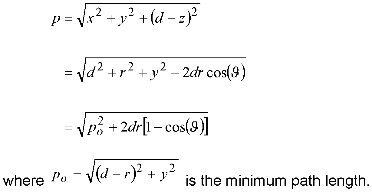
Figure 12 illustrates typical variations of the path length against angle for different sensor locations and offset from the sensor. Note that points on the circle
{d - rf + y2 = p
will produce the same minimum path length and the path length variation will be very similar.
The path length determines the delay of the received signal as c where c is the speed of light.
This delay results in a phase shift on the down-converted received signal of φ = 2TrfcT c λ where ^c and ^ are the frequency and wavelength of the sensor rf. The down-converted received signal can be approximated by

n
The constant complex term s° is a result of direct coupling between the transmitted and received signal. This value is not currently known. An estimate of its value has been made from the data measured without the engine running, but the accuracy of this estimate is not known and will affect the results obtained from processing the data.
In the above expression, the subscript n is an index to the returns from points on all the blades. The time dependence of the time delay and phase is explicitly shown by replacing the angle variable by its time dependence. The trials data is obtained by sampling this signal at a rate ^s . τ (t)
The time delay w / is negligible compared to the sampling rate and is s (t)
ignored in the following analysis. n > is an unknown pulse shape for the signal return, dependent on the path length and the shape of the blade. The amplitude dependence on the path length is of the form

This is a reasonable approximation about the minimum path length when the returned signal is a reflection from a flat region of the blade tip. However, there will also be returns from the leading and trailing edges where the return is from scattering on sharp edges and corners. This is difficult to model theoretically and an approximation will be used of the form

The parameters n , / n , and n will be obtained by fitting to the data.
A return from a point on the blade when it is passing under the sensor, tyi is the time of the signal return and the path length will vary about the minimum path length. However, there can be returns from a point on the blade when it is not under the sensor and the path length will not necessarily contain the minimum path length and can be very non-symmetric.
By extracting the phase variation for returns from points under the sensor, the minimum path length can be obtained. As shown earlier, the location of the blade point, given by ^ ~ rn ano; ^« wj|| De on a circle of radius
Pno 7he variation of the path length can be used to find the point on the circle using the approximation

Pno
From this fit, the value of Vn can be found, since d js known.
A problem with this approach is that the value of ^no can only be determined in the range (°'27r). Then the true value of the minimum path length will be Pno + ^ , where k is unknown. The variation of the phase can be used to
help resolve this ambiguity by finding the best solution using a multiple hypothesis approach.
The bias in the data makes the determination of the phase error prone. Consider the time derivative of the received data stream

n
The approximation assumes that the variation of phase is more significant over the pulse shape than the variation in the pulse shape. Figure 13 shows the rate of change of path length for a range of parameter values. About the minimum path length, the rate of change of path length or phase will be rapid with angle. This provides a good discriminator for determining the returns from points under the sensor. However it will give the minimum path length. The returns from the points under the sensor can determine the bias in the data.
To illustrate these modelling assumptions, a time block of the trials data has been processed corresponding to the estimated time interval for the blade spacing. Figure 14 illustrates the normalised in-phase and quadrature components of the signal over this time interval. The data has been interpolated using cubic splines to give a high sampling rate. There may be up to 10 returns in this data. Figure 15 illustrates the time derivative of these components. A more informative representation of the derivative data is shown in Figure 16 for the amplitude and Figure 17 for the phase data. There are multiple places where the phase folds over between ± π . There will also be a phase shift in the data of π due to the reflection of the signal. When processing the data this phase shift would be removed, by a technique known generally as "unfolding", but has been left in this plot to show the responses corresponding to returns from under the sensor. There is a rapid change in phase about these points. Note that these points correspond to minima in the amplitude variation. The use of a higher sampling rate will reduce these minima to zero.
There will be additional minima in the amplitude data which correspond to returns from the blades not directly below the sensor. At these points the rate of change of path length or phase is small and will not always change sign.
From the measured complex data it is possible to calculate the time derivative of the received signal (Figure 15) and the resulting time derivative can be expressed as amplitude and phase (Figures 16 and 17 respectively).
From the point of minimum path the return from under the sensor can be identified s(t) = s0 + sne i<P„ (0 such that i<P„ (0
t) = -<Pn (t)sne
This is assuming that the various returns to not interfere significantly with the value close to the identified returns.
It was previously shown that the time derivative of the path length for these returns can be approximated by
 where
where

Then

Consider the data at two times tyn and tk , either side of the minima, such that ^ = ~¾ . Then

and
 Y tm )- 3(tm f / 6 which can be re-arranged to give

Using this value of y, the bias can be found as

Because of the assumptions made in the evaluation of the bias, an estimate can be obtained from all the returns and averaged to give the final estimate of the bias.
Removing the bias from the data will allow the minimum path length to be extracted and the location of the point on a blade returning the signal to be found.
This will enable a time series of data responding to the return from individual blades as they pass under the sensor. This also applies to the bistatic case.
Analysis of the measured data in for example sequential blocks, relating to the rotation rate of the engine will enable parameters relating to individual blades to be determined.
For example this will include at least:
1 : Blade Clearance
2: Blade Vibration
It will be apparent from the foregoing description that modifications and variations can be made to the described embodiments without departing from the scope of the invention as claimed.
Claims
CLAIMS A blade monitoring system for a turbine assembly comprising rotating blades, the system comprising at least one sensor for transmitting a signal towards said rotating blades and detecting a time-varying return signal therefrom, and one or more processors configured to calculate the time derivative of said return signal, generate a phase variation signal for said time derivative, determine minima points within said phase variation signal and measure said signal at said minima points so as to identify data representative of respective minimum path lengths, each said minimum path length corresponding to the returned signal as each respective blade passes said sensor, and generate, using said minimum path lengths, a time series of data representing the returned signal from individual blades as they pass the sensor.
2. A system according to claim 1 , wherein the transmitted signal is a wideband signal for enabling a return signal to be collected from substantially a complete blade and/or shaft to be collected.
3. A system, according to claim 1 or claim 2, comprising a monostatic sensor, which is configured to transmit said signal towards said rotating blades and receive said returned signal.
4. A system according to claim 3, wherein said at least one processor is configured to estimate and remove a DC component from said returned signal.
5. A system according to claim 1 or claim 2, comprising a bistatic sensor arrangement comprising a first sensor for transmitting said signal towards said rotating blades, and a second sensor for receiving said returned signal.
6. A system according to any of the preceding claims, wherein said one or more processor is configured to identify and remove a bias from the signal before generating said time series.
7. A system according to any of the preceding claims, wherein said signal is a radar signal.
8. A system according to claim 7, wherein said signal comprises a continuous wave radar signal.
9. A system according to any of the preceding claims, wherein the or each sensor comprises a probe located within an existing horoscope or inspection hole or aperture in said turbine assembly.
10. A method of generating, in an engine health monitoring system for a turbine assembly comprising a plurality of rotating blades, a time series of data representative of a returned signal as individual blades pass a sensor, the method comprising obtaining a time-varying return signal from said rotating blades, calculating the time derivative of said return signal, generating a phase variation signal for said time derivative, determining minima points within said phase variation signal and measuring said signal at said minima points so as to identify data representative of respective minimum path lengths, each said minimum path length corresponding to the returned signal as each respective blade passes said sensor, and generating, using said minimum path lengths, a time series of data representing the returned signal from individual blades as they pass the sensor.
1 1 . A method according to claim 10, further comprising the step of estimating and removing a DC component from said return signal.
12. A program or plurality of programs arranged such that when executed by a computer system or one or more processors, it/they cause the computer system or the one or more processors to operate in accordance with the method of claim 10 or claim 1 1 .
13. A machine readable storage medium storing a program or at least one of the plurality of programs according to claim 12.
14. An engine health monitoring system for a turbine assembly comprising a plurality of rotating blades, comprising a system
according to any of claims 1 to 9 for generating a time series of data representing a returned signal from individual blades as they pass the sensor, and an analysis module configured, in use, to determine sequential blocks of said time series of data
corresponding to the rotation rate of said rotating blades, and calculating in respect of each of a plurality of said blades data representative of at least one of blade clearance and blade vibration.
15. An engine health monitoring system according to claim 14, wherein said analysis module is configured to calculate in respect of each of said plurality of blades data representative of blade clearance, the system further comprising a clearance control mechanism for controlling at least one operating parameter of said turbine assembly in response to said data representative of blade clearance.
Priority Applications (2)
| Application Number | Priority Date | Filing Date | Title |
|---|---|---|---|
| US15/329,381 US9995167B2 (en) | 2014-08-01 | 2015-07-28 | Turbine blade monitoring |
| EP15744321.9A EP3175259A1 (en) | 2014-08-01 | 2015-07-28 | Turbine blade monitoring |
Applications Claiming Priority (2)
| Application Number | Priority Date | Filing Date | Title |
|---|---|---|---|
| GB1413690.7 | 2014-08-01 | ||
| GB1413690.7A GB2528882A (en) | 2014-08-01 | 2014-08-01 | Turbine blade monitoring |
Publications (1)
| Publication Number | Publication Date |
|---|---|
| WO2016016632A1 true WO2016016632A1 (en) | 2016-02-04 |
Family
ID=51587619
Family Applications (1)
| Application Number | Title | Priority Date | Filing Date |
|---|---|---|---|
| PCT/GB2015/052174 Ceased WO2016016632A1 (en) | 2014-08-01 | 2015-07-28 | Turbine blade monitoring |
Country Status (4)
| Country | Link |
|---|---|
| US (1) | US9995167B2 (en) |
| EP (1) | EP3175259A1 (en) |
| GB (1) | GB2528882A (en) |
| WO (1) | WO2016016632A1 (en) |
Cited By (3)
| Publication number | Priority date | Publication date | Assignee | Title |
|---|---|---|---|---|
| WO2018002818A1 (en) * | 2016-06-27 | 2018-01-04 | University Of Pretoria | A method and system for monitoring rotor blades of a turbomachine using blade tip timing (btt) |
| CN108957443A (en) * | 2018-07-16 | 2018-12-07 | 北京航空航天大学 | A kind of estimation method based on double the unmanned plane rotor length for sending out double receipts coherent radars and revolving speed |
| US20230279872A1 (en) * | 2022-03-04 | 2023-09-07 | General Electric Company | Gas turbine engine with variable pitch inlet pre-swirl features |
Families Citing this family (12)
| Publication number | Priority date | Publication date | Assignee | Title |
|---|---|---|---|---|
| US20160103162A1 (en) * | 2014-10-14 | 2016-04-14 | The Boeing Company | Vehicle power flow monitoring |
| JP6458767B2 (en) * | 2016-05-17 | 2019-01-30 | トヨタ自動車株式会社 | Soft sensor device |
| FR3076361B1 (en) * | 2018-01-04 | 2019-12-13 | Safran Aircraft Engines | ADAPTIVE FILTERING PROCESS |
| US10705198B2 (en) * | 2018-03-27 | 2020-07-07 | Infineon Technologies Ag | System and method of monitoring an air flow using a millimeter-wave radar sensor |
| US11035931B1 (en) * | 2018-10-29 | 2021-06-15 | Ansys, Inc. | Accelerated radar data processing via limited pulse extrapolation |
| FR3103212B1 (en) * | 2019-11-14 | 2022-04-01 | Safran Aircraft Engines | Modular and autonomous assembly for detecting the angular position of the blades of a blade wheel and modular and autonomous assembly for detecting damage to the blades of a blade wheel of a turbomachine |
| EP3868651B1 (en) | 2020-02-19 | 2023-08-30 | Ratier-Figeac SAS | Health monitoring based on blade tip trajectory |
| EP4016128A1 (en) * | 2020-12-15 | 2022-06-22 | Rolls-Royce Deutschland Ltd & Co KG | Method and system of monitoring a component of an aircraft |
| US12209557B1 (en) | 2023-11-30 | 2025-01-28 | General Electric Company | Gas turbine engine with forward swept outlet guide vanes |
| US12385430B2 (en) | 2023-11-30 | 2025-08-12 | General Electric Company | Gas turbine engine with forward swept outlet guide vanes |
| US12228037B1 (en) | 2023-12-04 | 2025-02-18 | General Electric Company | Guide vane assembly with fixed and variable pitch inlet guide vanes |
| US12313021B1 (en) | 2024-03-14 | 2025-05-27 | General Electric Company | Outer nacelle with inlet guide vanes and acoustic treatment |
Citations (4)
| Publication number | Priority date | Publication date | Assignee | Title |
|---|---|---|---|---|
| US20080255799A1 (en) * | 2004-07-12 | 2008-10-16 | Uwe Pfeifer | Determination of the Gap Size of a Radial Gap |
| US7483800B2 (en) * | 2006-06-01 | 2009-01-27 | Radatec, Inc. | Peak detection and clutter reduction for a microwave sensor |
| US20090243628A1 (en) * | 2008-03-25 | 2009-10-01 | General Electric Company | Systems and methods for online phase calibration |
| US7969165B2 (en) * | 2006-09-29 | 2011-06-28 | Siemens Aktiengesellschaft | Device for determining the distance between a rotor blade and a wall of a turbine engine surrounding the rotor blade |
Family Cites Families (15)
| Publication number | Priority date | Publication date | Assignee | Title |
|---|---|---|---|---|
| US4275396A (en) | 1979-10-12 | 1981-06-23 | Jacomini Omar J | Helicopter rotating blade detection system |
| US4684950A (en) | 1984-07-20 | 1987-08-04 | Long Maurice W | Methods of and circuits for suppressing doppler radar clutter |
| DE4220429A1 (en) | 1992-06-24 | 1994-01-05 | Atlas Elektronik Gmbh | Detection and=or classification of noise from propeller-driven vessel - filtering, band-limiting, envelope demodulating and using FFT and fuzzy logic to evaluate fundamental frequencies of spectral lines or harmonics by associating with correspondence functions to produce reliability values. |
| US5539412A (en) | 1994-04-29 | 1996-07-23 | Litton Systems, Inc. | Radar system with adaptive clutter suppression |
| GB2322987A (en) | 1997-03-06 | 1998-09-09 | Marconi Gec Ltd | Object detection in turbine influx or efflux |
| DE10351154B3 (en) | 2003-11-03 | 2005-01-05 | Eads Deutschland Gmbh | Jet engine modulation signal suppression method for reception signals for high pulse repetition frequency radar device uses transmission signal bursts with different transmission frequencies |
| US7328587B2 (en) * | 2004-01-23 | 2008-02-12 | York International Corporation | Integrated adaptive capacity control for a steam turbine powered chiller unit |
| US7455495B2 (en) * | 2005-08-16 | 2008-11-25 | United Technologies Corporation | Systems and methods for monitoring thermal growth and controlling clearances, and maintaining health of turbo machinery applications |
| DE102006033461A1 (en) * | 2006-07-19 | 2008-01-31 | Siemens Ag | Radial gap measurement on turbines |
| GB2448886B (en) | 2007-05-01 | 2009-06-17 | Rolls Royce Plc | Turbomachine blade |
| US8296037B2 (en) * | 2008-06-20 | 2012-10-23 | General Electric Company | Method, system, and apparatus for reducing a turbine clearance |
| EP2345909A1 (en) | 2010-01-07 | 2011-07-20 | BAE Systems PLC | A method of detecting a clutter return at a sensor |
| WO2012129377A1 (en) | 2011-03-23 | 2012-09-27 | Meggitt Sa | Measurement of bladed rotors |
| US8459103B2 (en) | 2011-06-24 | 2013-06-11 | United Technologies Corporation | IDMS signal processing to distinguish inlet particulates |
| GB2528880A (en) | 2014-08-01 | 2016-02-10 | Bae Systems Plc | Foreign object debris detection system and method |
-
2014
- 2014-08-01 GB GB1413690.7A patent/GB2528882A/en not_active Withdrawn
-
2015
- 2015-07-28 EP EP15744321.9A patent/EP3175259A1/en not_active Withdrawn
- 2015-07-28 WO PCT/GB2015/052174 patent/WO2016016632A1/en not_active Ceased
- 2015-07-28 US US15/329,381 patent/US9995167B2/en not_active Expired - Fee Related
Patent Citations (4)
| Publication number | Priority date | Publication date | Assignee | Title |
|---|---|---|---|---|
| US20080255799A1 (en) * | 2004-07-12 | 2008-10-16 | Uwe Pfeifer | Determination of the Gap Size of a Radial Gap |
| US7483800B2 (en) * | 2006-06-01 | 2009-01-27 | Radatec, Inc. | Peak detection and clutter reduction for a microwave sensor |
| US7969165B2 (en) * | 2006-09-29 | 2011-06-28 | Siemens Aktiengesellschaft | Device for determining the distance between a rotor blade and a wall of a turbine engine surrounding the rotor blade |
| US20090243628A1 (en) * | 2008-03-25 | 2009-10-01 | General Electric Company | Systems and methods for online phase calibration |
Non-Patent Citations (1)
| Title |
|---|
| SCHICHT A ET AL: "Absolute Phase-Based Distance Measurement for Industrial Monitoring Systems", IEEE SENSORS JOURNAL, IEEE SERVICE CENTER, NEW YORK, NY, US, vol. 9, no. 9, 1 September 2009 (2009-09-01), pages 1007 - 1013, XP011271201, ISSN: 1530-437X, DOI: 10.1109/JSEN.2009.2025582 * |
Cited By (9)
| Publication number | Priority date | Publication date | Assignee | Title |
|---|---|---|---|---|
| WO2018002818A1 (en) * | 2016-06-27 | 2018-01-04 | University Of Pretoria | A method and system for monitoring rotor blades of a turbomachine using blade tip timing (btt) |
| CN109716077A (en) * | 2016-06-27 | 2019-05-03 | 比勒陀利亚大学 | Use the method and system of Tip-Timing (BTT) monitoring turbine rotor blade |
| CN109716077B (en) * | 2016-06-27 | 2021-04-27 | 比勒陀利亚大学 | Method and system for monitoring turbine rotor blades using blade tip timing (BTT) |
| US11609114B2 (en) | 2016-06-27 | 2023-03-21 | University Of Pretoria | Method and system for monitoring rotor blades of a turbomachine using blade tip timing (BTT) |
| CN108957443A (en) * | 2018-07-16 | 2018-12-07 | 北京航空航天大学 | A kind of estimation method based on double the unmanned plane rotor length for sending out double receipts coherent radars and revolving speed |
| CN108957443B (en) * | 2018-07-16 | 2022-07-05 | 北京航空航天大学 | Method for estimating rotor length and rotating speed of unmanned aerial vehicle based on double-transmitting and double-receiving coherent radar |
| US20230279872A1 (en) * | 2022-03-04 | 2023-09-07 | General Electric Company | Gas turbine engine with variable pitch inlet pre-swirl features |
| US11808281B2 (en) * | 2022-03-04 | 2023-11-07 | General Electric Company | Gas turbine engine with variable pitch inlet pre-swirl features |
| US12221980B2 (en) | 2022-03-04 | 2025-02-11 | General Electric Company | Gas turbine engine with variable pitch inlet pre-swirl features |
Also Published As
| Publication number | Publication date |
|---|---|
| US9995167B2 (en) | 2018-06-12 |
| GB2528882A (en) | 2016-02-10 |
| US20170211411A1 (en) | 2017-07-27 |
| GB201413690D0 (en) | 2014-09-17 |
| EP3175259A1 (en) | 2017-06-07 |
Similar Documents
| Publication | Publication Date | Title |
|---|---|---|
| US9995167B2 (en) | Turbine blade monitoring | |
| Diamond et al. | Improved blade tip timing measurements during transient conditions using a state space model | |
| Joung et al. | Analysis of vibration of the turbine blades using non-intrusive stress measurement system | |
| JP7358205B2 (en) | Method and system for monitoring rotor blades of a turbine engine | |
| EP1813778B1 (en) | Method of monitoring blade vibration in a turbine engine | |
| US20080206057A1 (en) | Blade shroud vibration monitor | |
| US9046000B2 (en) | Method for detecting foreign object damage in turbomachinery | |
| US20060171806A1 (en) | Turbine blade for monitoring torsional blade vibration | |
| US11994033B2 (en) | Modular and autonomous assembly for detecting the angular position of the blades of an impeller and modular and autonomous assembly for detecting damage to the blades of an impeller of a turbine engine | |
| US11193388B2 (en) | Methods and systems for monitoring rotor blades in turbine engines | |
| US20170219699A1 (en) | Foreign object debris detection system and method | |
| Woike et al. | Testing of a microwave blade tip clearance sensor at the NASA Glenn Research Center | |
| US11333572B2 (en) | Method and system for detecting damage to the mobile blades of an aircraft | |
| US20070063697A1 (en) | System and method for temperature independent measurement of standoff distance using an eddy current sensor | |
| CN114902031A (en) | Method, device, system, aircraft and computer program product for monitoring a turbomachine | |
| Woike et al. | A microwave blade tip clearance sensor for propulsion health monitoring | |
| Grądzki et al. | Rotor blades diagnosis method based on differences in phase shifts | |
| Aldabaldetreku et al. | Real-time bilevel algorithm for blade tip clearance and tip timing estimation in aircraft engines | |
| Geisheimer et al. | Blade tip clearance sensors for use in engine health monitoring applications | |
| US20210140337A1 (en) | Turbine and compressor blade deformation and axial shift monitoring by pattern deployment and tracking in blade pockets | |
| Heimes et al. | Recent Progress with the Engine Health Diagnostics Using Radar System | |
| GB2322988A (en) | Damage assessment using radar | |
| Zimmer | Investigation of the impact of turbine blade geometry on near-field microwave blade tip time of arrival measurements | |
| Przysowa et al. | Health monitoring of turbomachinery based on blade tip-timing and tip-clearance | |
| Perz et al. | Turbine Blade and Exhaust Gas Flow Monitoring Using Microwave Probes |
Legal Events
| Date | Code | Title | Description |
|---|---|---|---|
| 121 | Ep: the epo has been informed by wipo that ep was designated in this application |
Ref document number: 15744321 Country of ref document: EP Kind code of ref document: A1 |
|
| WWE | Wipo information: entry into national phase |
Ref document number: 15329381 Country of ref document: US |
|
| NENP | Non-entry into the national phase |
Ref country code: DE |
|
| REEP | Request for entry into the european phase |
Ref document number: 2015744321 Country of ref document: EP |
|
| WWE | Wipo information: entry into national phase |
Ref document number: 2015744321 Country of ref document: EP |