WO2016017426A1 - 制御装置、機器制御装置、制御方法、通知受信方法、通知方法および記録媒体 - Google Patents
制御装置、機器制御装置、制御方法、通知受信方法、通知方法および記録媒体 Download PDFInfo
- Publication number
- WO2016017426A1 WO2016017426A1 PCT/JP2015/070256 JP2015070256W WO2016017426A1 WO 2016017426 A1 WO2016017426 A1 WO 2016017426A1 JP 2015070256 W JP2015070256 W JP 2015070256W WO 2016017426 A1 WO2016017426 A1 WO 2016017426A1
- Authority
- WO
- WIPO (PCT)
- Prior art keywords
- power supply
- demand adjustment
- storage battery
- application
- information
- Prior art date
- Legal status (The legal status is an assumption and is not a legal conclusion. Google has not performed a legal analysis and makes no representation as to the accuracy of the status listed.)
- Ceased
Links
Images


Classifications
-
- H—ELECTRICITY
- H02—GENERATION; CONVERSION OR DISTRIBUTION OF ELECTRIC POWER
- H02J—ELECTRIC POWER NETWORKS; CIRCUIT ARRANGEMENTS OR SYSTEMS FOR SUPPLYING OR DISTRIBUTING ELECTRIC POWER; SYSTEMS FOR STORING ELECTRIC ENERGY
- H02J3/00—Circuit arrangements for AC mains or AC distribution networks
- H02J3/28—Arrangements for balancing of the load in networks by storage of energy
- H02J3/32—Arrangements for balancing of the load in networks by storage of energy using batteries or super capacitors with converting means
-
- G—PHYSICS
- G05—CONTROLLING; REGULATING
- G05B—CONTROL OR REGULATING SYSTEMS IN GENERAL; FUNCTIONAL ELEMENTS OF SUCH SYSTEMS; MONITORING OR TESTING ARRANGEMENTS FOR SUCH SYSTEMS OR ELEMENTS
- G05B19/00—Program-control systems
- G05B19/02—Program-control systems electric
- G05B19/04—Program control other than numerical control, i.e. in sequence controllers or logic controllers
- G05B19/042—Program control other than numerical control, i.e. in sequence controllers or logic controllers using digital processors
-
- G—PHYSICS
- G06—COMPUTING OR CALCULATING; COUNTING
- G06Q—INFORMATION AND COMMUNICATION TECHNOLOGY [ICT] SPECIALLY ADAPTED FOR ADMINISTRATIVE, COMMERCIAL, FINANCIAL, MANAGERIAL OR SUPERVISORY PURPOSES; SYSTEMS OR METHODS SPECIALLY ADAPTED FOR ADMINISTRATIVE, COMMERCIAL, FINANCIAL, MANAGERIAL OR SUPERVISORY PURPOSES, NOT OTHERWISE PROVIDED FOR
- G06Q50/00—Information and communication technology [ICT] specially adapted for implementation of business processes of specific business sectors, e.g. utilities or tourism
- G06Q50/06—Energy or water supply
-
- H—ELECTRICITY
- H02—GENERATION; CONVERSION OR DISTRIBUTION OF ELECTRIC POWER
- H02J—ELECTRIC POWER NETWORKS; CIRCUIT ARRANGEMENTS OR SYSTEMS FOR SUPPLYING OR DISTRIBUTING ELECTRIC POWER; SYSTEMS FOR STORING ELECTRIC ENERGY
- H02J13/00—Circuit arrangements for providing remote monitoring or remote control of equipment in a power distribution network
-
- H—ELECTRICITY
- H04—ELECTRIC COMMUNICATION TECHNIQUE
- H04Q—SELECTING
- H04Q9/00—Arrangements in telecontrol or telemetry systems for selectively calling a substation from a main station, in which substation desired apparatus is selected for applying a control signal thereto or for obtaining measured values therefrom
-
- G—PHYSICS
- G05—CONTROLLING; REGULATING
- G05B—CONTROL OR REGULATING SYSTEMS IN GENERAL; FUNCTIONAL ELEMENTS OF SUCH SYSTEMS; MONITORING OR TESTING ARRANGEMENTS FOR SUCH SYSTEMS OR ELEMENTS
- G05B2219/00—Program-control systems
- G05B2219/20—Pc systems
- G05B2219/25—Pc structure of the system
- G05B2219/25318—Power supply module in common for all modules
-
- G—PHYSICS
- G05—CONTROLLING; REGULATING
- G05B—CONTROL OR REGULATING SYSTEMS IN GENERAL; FUNCTIONAL ELEMENTS OF SUCH SYSTEMS; MONITORING OR TESTING ARRANGEMENTS FOR SUCH SYSTEMS OR ELEMENTS
- G05B2219/00—Program-control systems
- G05B2219/20—Pc systems
- G05B2219/26—Pc applications
- G05B2219/2639—Energy management, use maximum of cheap power, keep peak load low
-
- Y—GENERAL TAGGING OF NEW TECHNOLOGICAL DEVELOPMENTS; GENERAL TAGGING OF CROSS-SECTIONAL TECHNOLOGIES SPANNING OVER SEVERAL SECTIONS OF THE IPC; TECHNICAL SUBJECTS COVERED BY FORMER USPC CROSS-REFERENCE ART COLLECTIONS [XRACs] AND DIGESTS
- Y02—TECHNOLOGIES OR APPLICATIONS FOR MITIGATION OR ADAPTATION AGAINST CLIMATE CHANGE
- Y02E—REDUCTION OF GREENHOUSE GAS [GHG] EMISSIONS, RELATED TO ENERGY GENERATION, TRANSMISSION OR DISTRIBUTION
- Y02E60/00—Enabling technologies; Technologies with a potential or indirect contribution to GHG emissions mitigation
-
- Y—GENERAL TAGGING OF NEW TECHNOLOGICAL DEVELOPMENTS; GENERAL TAGGING OF CROSS-SECTIONAL TECHNOLOGIES SPANNING OVER SEVERAL SECTIONS OF THE IPC; TECHNICAL SUBJECTS COVERED BY FORMER USPC CROSS-REFERENCE ART COLLECTIONS [XRACs] AND DIGESTS
- Y04—INFORMATION OR COMMUNICATION TECHNOLOGIES HAVING AN IMPACT ON OTHER TECHNOLOGY AREAS
- Y04S—SYSTEMS INTEGRATING TECHNOLOGIES RELATED TO POWER NETWORK OPERATION, COMMUNICATION OR INFORMATION TECHNOLOGIES FOR IMPROVING THE ELECTRICAL POWER GENERATION, TRANSMISSION, DISTRIBUTION, MANAGEMENT OR USAGE, i.e. SMART GRIDS
- Y04S10/00—Systems supporting electrical power generation, transmission or distribution
- Y04S10/14—Energy storage units
Definitions
- the present invention relates to a control device, a device control device, a control method, a notification reception method, a notification method, and a program, and in particular, a control device, a device control device, a control method, and a power supply / demand adjustment device used for power supply / demand adjustment processing,
- the present invention relates to a notification receiving method, a notification method, and a program.
- Patent Document 1 describes a DR system that controls an electric device that functions as a power supply and demand adjustment device and executes power supply and demand adjustment processing according to a DR (demand response) contract.
- the “power supply and demand adjustment process” is also simply referred to as “adjustment process”.
- the DR system described in Patent Document 1 has one or more adjustment processes (a peak cut process for reducing power demand and a frequency adjustment process for adjusting the frequency of the power system) corresponding to each of a plurality of DR contracts. It is executed by controlling the operation of the electrical equipment.
- the plurality of adjustment processes executed by the DR system described in Patent Literature 1 have different processing contents (for example, peak cut processing and frequency adjustment processing) depending on the purpose of power supply and demand adjustment. For this reason, the characteristics of the adjustment process are different for each adjustment process.
- a power supply / demand adjustment device such as an electric device that does not correspond to the characteristics of the adjustment process is selected as the power supply / demand adjustment device (use target device) used when the adjustment process is executed. If this happens, the adjustment process cannot be executed properly.
- An object of the present invention is to provide a control device, a device control device, a control method, a notification reception method, a notification method, and a program that can solve the above-described problems.
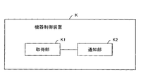
- the control device of the present invention includes an acquisition unit that acquires information about the power supply / demand adjustment device shown for each power supply / demand adjustment device, information indicating characteristics of the power supply / demand adjustment processing, information about the power supply / demand adjustment device, A notification unit configured to notify the power supply and demand adjustment device to be subjected to the power supply and demand adjustment process based on information indicating characteristics of the power supply and demand adjustment process.
- the device control apparatus of the present invention is a pre-power determined based on a communication unit that transmits information related to a power supply / demand adjustment device to an external device, information related to the power supply / demand adjustment device, and information indicating characteristics related to power supply / demand adjustment processing.
- a receiving unit configured to receive a notification of activation of supply and demand adjustment processing;
- the apparatus control device of the present invention includes an acquisition unit that acquires information on the power supply and demand adjustment device shown for each power supply and demand adjustment device, information indicating characteristics of the power supply and demand adjustment processing, and information on the power supply and demand adjustment device And a notification unit that notifies an external device that the power supply / demand adjustment device corresponds to the characteristic of the power supply / demand adjustment processing based on the information indicating the characteristics of the power supply / demand adjustment processing.
- the control method of the present invention obtains information on the power supply / demand adjustment device shown for each power supply / demand adjustment device and information indicating the characteristics of the power supply / demand adjustment processing, information on the power supply / demand adjustment device, and the power supply / demand balance Based on the information indicating the characteristics of the adjustment process, the power supply / demand adjustment apparatus that is the object of the power supply / demand adjustment process is notified of the activation of the power supply / demand adjustment process.
- the notification receiving method of the present invention transmits information related to the power supply / demand adjustment device to an external device, and the previous power supply / demand adjustment processing determined based on the information related to the power supply / demand adjustment device and information indicating characteristics related to the power supply / demand adjustment processing Receive notification of activation.
- the notification method of the present invention obtains information relating to the power supply / demand adjustment device shown for each power supply / demand adjustment device and information indicating the characteristics of the power supply / demand adjustment processing, information relating to the power supply / demand adjustment device, and the power supply / demand balance Based on the information indicating the characteristics of the adjustment process, the external apparatus is notified that the power supply / demand adjustment apparatus corresponds to the characteristic of the power supply / demand adjustment process.
- the recording medium of the present invention relates to an acquisition procedure for acquiring, in a computer, information related to the power supply / demand adjustment device shown for each power supply / demand adjustment device, and information indicating characteristics of the power supply / demand adjustment processing, and the power supply / demand adjustment device
- the recording medium of the present invention is determined based on a transmission procedure for transmitting information relating to the power supply / demand adjustment device to an external device, information relating to the power supply / demand adjustment device, and information indicating characteristics relating to the power supply / demand adjustment processing. It is a computer-readable recording medium which recorded the program which performs the reception procedure which receives the notification of the trigger of the previous electric power supply and demand adjustment process.
- the recording medium of the present invention relates to an acquisition procedure for acquiring, in a computer, information related to the power supply / demand adjustment device shown for each power supply / demand adjustment device, and information indicating characteristics of the power supply / demand adjustment processing, and the power supply / demand adjustment device Based on the information and information indicating the characteristics of the power supply and demand adjustment process, a notification procedure for performing notification to the external device that the power supply and demand adjustment apparatus corresponds to the characteristics of the power supply and demand adjustment process is executed.
- the present invention it is possible to suppress the selection of the power supply / demand adjustment device that does not correspond to the characteristics of the power supply / demand adjustment processing as the power supply / demand adjustment device used when the power supply / demand adjustment processing is executed.
- FIG. 5 is a diagram illustrating an example of response times required by applications AP1 to AP3. 3 is a flowchart for explaining an operation of a control device A. It is the figure which showed the control apparatus B of 2nd Embodiment of this invention. FIG. 5 is a diagram showing an example of response times and communication reliability of applications AP1 to AP3. 3 is a flowchart for explaining an operation of a control device B.
- FIG. 5 is a diagram illustrating an example of response times, communication reliability, and profitability of applications AP1 to AP3. It is the figure which showed an example of the profit conditions of storage battery R3-1 to R3-n. It is a flowchart for demonstrating the operation
- FIG. 5 is a diagram illustrating an example of response times, communication reliability, profitability, reliability, and execution time of applications AP1 to AP3. It is the figure which showed an example of the implementation guarantee property and use permissible period of storage battery R3-1 to R3-n. It is a flowchart for demonstrating the operation
- FIG. It is the figure which showed an example of the electric power feeding instruction
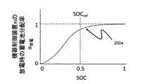
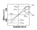
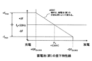
- FIG. It is the figure which showed an example of the storage battery distribution rate curve 202a at the time of discharge. It is the figure which showed an example of the storage battery distribution rate curve 202b at the time of charge. It is the figure which showed an example of the DR2 charging / discharging gain line. It is the figure which showed an example of DR3 drooping characteristic line. It is a flowchart for demonstrating the operation
- FIG. 10 is a sequence diagram for explaining a P ES-DR2 deriving operation. It is a sequence diagram for demonstrating DR2 grasp operation
- FIG. 1A is a diagram illustrating a control device A according to the first embodiment of the present invention.
- the control device A includes an acquisition unit A1 and a notification unit A2.
- Acquisition part A1 acquires the information regarding the storage battery shown for every storage battery, and the information which shows the characteristic of an electric power supply-and-demand adjustment process.
- power demand reduction processing LFC (Load Frequency Control) processing
- GF Governor Free processing
- the plurality of types of power supply and demand adjustment processing are not limited to power demand reduction processing, LFC processing, and GF processing, and can be changed as appropriate.
- the number of types of power supply and demand adjustment processing is not limited to three, but may be one or more.
- the power demand reduction process, the LFC process, and the GF process are referred to as “application AP1,” “application AP2,” and “application AP3,” respectively.
- the application AP1 (demand reduction process) is a process for performing, for example, a peak cut of power demand.
- Application AP2 (LFC process) and application AP3 (GF process) are processes for controlling (stabilizing) the system frequency of the power system.
- Each of the applications AP1 to AP3 is a process for adjusting power supply and demand by controlling charging and discharging of a storage battery connected to the power system.
- the storage battery is an example of a power supply and demand adjustment device.
- the power supply and demand adjustment device is not limited to the storage battery and can be changed as appropriate.
- an electric device, an electric water heater, a heat pump water heater, a pump, or an electric vehicle may be used as the power supply / demand adjustment device.
- Acquisition part A1 acquires the information which shows the response time which each application requires as an example of the information which shows the characteristic of each application.
- “response time required by the application” is also referred to as “response time of the application”.
- the app response time is an example of response characteristics required by the app.
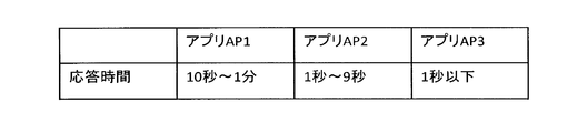
- FIG. 2 is a diagram illustrating an example of each response time required by the applications AP1 to AP3.
- the response time required by the application AP1 (demand reduction processing) is 10 seconds to 1 minute.
- the response time required by application AP2 is 1 to 9 seconds.
- the response time required by application AP3 (GF processing) is 1 second or less.
- Acquisition part A1 acquires the information which shows the response time of each storage battery connected to the electric power grid
- the information indicating the response time of each storage battery is an example of information regarding each storage battery.
- the response time (response time) refers to the time required from the execution instruction of processing to the first response.
- the response time is the time required to match the power demand curve by performing the process with respect to the “target of the power demand curve” (for example, the app AP1 is 10 seconds) ⁇ 1 minute, application AP2 is 1-9 seconds, application AP3 is less than 1 second).
- the response time is the time from when an instruction is received to perform the processing until charging / discharging is performed.
- the notification unit A2 determines, based on the information indicating the response time of each application and the information indicating the response time of each storage battery, the storage battery having a response time that is equal to or less than the response time of the application for each application. Notify activation.
- a storage battery having a response time that is equal to or shorter than the response time of the application is an example of a storage battery that is a target of the application (hereinafter also referred to as “use target storage battery”) or a storage battery that corresponds to the response time of the application.
- the target storage battery is an example of a target device.
- the storage battery used for the application is a storage battery used when the application is executed.
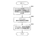
- FIG. 3 is a flowchart for explaining the operation of the control device A.
- Acquisition part A1 acquires the information which shows the response time of each application, and the information which shows the response time of each storage battery (step S301). For example, acquisition part A1 acquires the information which shows the response time of each application, and the information which shows the response time of each storage battery from an external device. In addition, acquisition part A1 may acquire the information which shows the response time of each application, and the information which shows the response time of each storage battery from a separate external device. Then, acquisition part A1 outputs the information which shows the response time of each application, and the information which shows the response time of each storage battery to notification part A2.
- the notification unit A2 When the notification unit A2 receives the information indicating the response time of each application and the information indicating the response time of each storage battery, the notification unit A2 operates as follows.
- the notification unit A2 selects, as the storage battery to be used, a storage battery having a response time equal to or shorter than the response time of the app for each app using information indicating the response time of each app and information indicating the response time of each storage battery. (Step S302).
- the notification unit A2 notifies the use target storage battery of the activation of the application (step S302).
- the use target storage battery receives the notification of the activation of the application, the usage target storage battery starts to execute the application.
- acquisition part A1 acquires the information which shows the response time of an application, and the information which shows the response time of a storage battery.
- the notification unit A2 notifies the activation of the application to a storage battery having a response time that is equal to or shorter than the response time of the application. For this reason, it becomes possible to suppress selecting a storage battery having a response time longer than the response time of the application as a storage battery to be used for the application. Therefore, possibility that the storage battery according to the characteristic of an application will be selected as a use object storage battery can be made high. Since the storage battery to be used corresponding to the characteristics of the application is used when the application is executed, the power supply / demand adjustment by the application can be executed with high accuracy.
- the response times of the apps AP1 to AP3 are not limited to 10 seconds to 1 minute, 1 second to 9 seconds, and 1 second or less, but can be changed as appropriate.
- each application is in accordance with the demand of the power company (request for power supply and demand adjustment processing)
- it is desirable that the response time of each application is set based on the required response time indicated in the demand.
- the response time of the application is used as the characteristic of the application, but the characteristic of the application is not limited to the response time and can be changed as appropriate.
- the notification unit A2 transmits the operation control information for controlling the operation of the use target storage battery according to the application to the device control apparatus that controls the use target storage battery of the application, and controls the operation of the use target storage battery of the application.
- the device control apparatus may be caused to execute processing that is controlled according to the operation control information.
- the operation control information is an example of an application activation notification.
- control device may include a storage unit that stores information indicating the response time of the application and a storage unit that stores information indicating the response time of the storage battery.
- FIG. 1B is a diagram illustrating a control device AA having a storage unit that stores information indicating the response time of the app and a storage unit that stores information indicating the response time of the storage battery.
- Control device AA includes storage units AA1 and AA2, and selection unit AA3.
- the storage unit AA1 is an example of a first storage unit.
- the storage unit AA2 is an example of a second storage unit.
- the storage unit AA1 stores information indicating response time required by each application (hereinafter, “information indicating response time” is also simply referred to as “response time”) as an example of the characteristics of each application.
- “response time required by the application” is also referred to as “response time of the application”.
- the app response time is an example of response characteristics required by the app.
- Storage part AA2 stores the information which shows the response time of each storage battery connected to the electric power grid
- “information indicating the response time of the storage battery” is also simply referred to as “response time of the storage battery”.
- the response time of each storage battery is an example of information on each storage battery.
- the selection unit AA3 includes an acquisition unit A1 and a notification unit A2.
- FIG. 1C is a diagram illustrating a control device AA including a selection unit AA3 including an acquisition unit A1 and a notification unit A2, and storage units AA1 and AA2.
- the selection unit AA3 acquires the response time of each application stored in the storage unit AA1 and the response time of each storage battery stored in the storage unit AA2.
- Selection part AA3 (notification part A2) selects the storage battery which has a response time below an application response time for every application as a use object storage battery for each application using the response time of each application, and the response time of each storage battery.
- a storage battery having a response time equal to or shorter than the response time of the application is an example of a storage battery corresponding to the response time of the application.
- the target storage battery is an example of a target device.
- the storage battery used for the application is a storage battery used when the application is executed.
- the selection unit AA3 (notification unit A2) notifies the application target storage battery of the activation of the application.
- the selection unit AA3 uses the response time of each app and the response time of each storage battery to respond to the app for each app. It has a function of selecting a storage battery having a response time equal to or less than the time as a target storage battery.
- the selection part may be inside a notification part and may be provided separately from a notification part.
- the storage unit may be inside the acquisition unit or may be provided separately from the acquisition unit.
- FIG. 4 is a diagram showing a control device B according to the second embodiment of the present invention.
- the main difference between the second embodiment and the first embodiment is that in the second embodiment, as the characteristics of the applications AP1 to AP3, in addition to the response time of each application, the communication characteristics required by each application are as follows. This is the point used.
- the second embodiment will be described focusing on differences from the first embodiment.
- Control device B includes storage units B1 and B2 and a selection unit B3.
- the storage unit B1 is an example of a first storage unit.
- the storage unit B1 includes information indicating communication characteristics required by each application (hereinafter, “information indicating communication characteristics”) simply as “communication characteristics”. (Also called).
- the communication reliability required by the application (information indicating the communication reliability required by the application) is used as the communication characteristic.
- “communication reliability required by the application” is also referred to as “communication reliability of the application”.
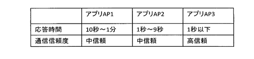
- FIG. 5 is a diagram illustrating an example of response times and communication reliability of the applications AP1 to AP3. The response times of the applications AP1 to AP3 are the same as those shown in FIG.
- the communication reliability required by the apps AP1 and AP2 is “medium trust”.
- the communication reliability required by the application AP3 is “high reliability”.
- the communication reliability (medium reliability and high reliability) is determined based on the communication mode (hereinafter referred to as “corresponding communication mode”) supported by the storage battery side.
- “High reliability” means that the corresponding communication mode is VPN (Virtual Private Network) or the Internet.
- a storage battery whose corresponding communication mode is VPN or Internet is a storage battery that can communicate via VPN or Internet.
- “Medium trust” means that the corresponding communication mode is 3G (3rd Generation) or the Internet.
- a storage battery whose corresponding communication mode is 3G or the Internet is a storage battery that can communicate via 3G or the Internet.
- the communication reliability is not limited to that determined based on the corresponding communication mode, and can be changed as appropriate.
- the communication reliability may be determined based on an error rate generated in communication with the storage battery side.
- “medium reliability” and “high reliability” may mean that the error rate is equal to or lower than a first threshold and the error rate is equal to or lower than a second threshold lower than the first threshold, respectively.
- the storage unit B2 is an example of a second storage unit.
- the storage unit B2 stores information indicating the response time of each storage battery connected to the power system and the corresponding communication mode.
- “information indicating the corresponding communication mode of the storage battery” is also simply referred to as “corresponding communication mode of the storage battery”.
- the correspondence communication mode of the storage battery is an example of information on the storage battery.
- the selection unit B3 includes an acquisition unit and a notification unit.
- the acquisition unit in the selection unit B3 acquires the response time of the application and the communication reliability of the application from the storage unit B1.
- the acquisition part in selection part B3 acquires the response time and corresponding
- the selection unit B3 refers to the response time of the app, the communication reliability of the app, the response time of each storage battery, and the corresponding communication mode, and corresponds to both the response time of the app and the communication reliability of the app for each app.
- a storage battery is selected as a target storage battery.
- the notification unit in the selection unit B3 notifies the application use target storage battery of the application for each application.
- FIG. 6 is a flowchart for explaining the operation of the control device B.
- the acquisition unit in the selection unit B3 acquires the response time of the app, the communication reliability of the app, the response time of each storage battery, and the corresponding communication mode (step S601). Subsequently, based on the response time of the app, the communication reliability of the app, the response time of each storage battery, and the corresponding communication mode, the selection unit B3 selects, for each app, from among the storage batteries having a response time equal to or shorter than the response time of the app. Then, a storage battery having a corresponding communication mode corresponding to the communication reliability of the app is selected as a target storage battery (step S602).
- the selection unit B3 uses VPN or the Internet as the corresponding communication mode corresponding to “high reliability” that is the communication reliability of the application.
- the selection unit B3 uses a VPN corresponding to “high reliability” as a corresponding communication mode corresponding to “medium reliability” that is the communication reliability of the application.
- selection part B3 may store the selection result of the use storage battery for every application in storage part B1.
- the notification unit in the selection unit B3 notifies the use target storage battery of the activation of the application for each application (step S603).
- the use target storage battery receives the notification of the activation of the application, the usage target storage battery starts to execute the application.
- the storage unit B1 stores response times and communication reliability required by each application.
- the storage unit B2 stores the response time and the corresponding communication mode of each storage battery connected to the power system.
- the selection unit B3 selects a storage battery corresponding to the response time and communication reliability of the application as a use target storage battery. For this reason, it becomes possible to suppress selecting a storage battery that does not correspond to at least one of the plurality of characteristics required by the application as a storage battery to be used for the application.
- the storage unit B1 may also serve as the storage unit B2.
- the storage unit B1 stores the response time and communication reliability required by each application, the response time of each storage battery, and the corresponding communication mode.
- the communication reliability of each of the applications AP1 to AP3 is not limited to “medium trust”, “medium trust”, and “high reliability”, and can be changed as appropriate.
- the response time and communication reliability of each application are set based on the response time and communication reliability required by the demand. It is desirable.
- the selection unit B3 transmits the operation control information for controlling the operation of the use target storage battery according to the application to the device control device that controls the use target storage battery of the application, and controls the operation of the use target storage battery of the application.
- the device control apparatus may be caused to execute processing that is controlled according to the operation control information.
- One or both of the storage unit B1 and the storage unit B2 may be incorporated in the selection unit B3.
- the storage unit B1 and the storage unit B2 may be memories built in the selection unit B3.
- the storage unit B1, the storage unit B2, and the selection unit B3 may be separate devices. Further, the storage unit B1 and the storage unit B2 may be built in the same device, and the selection unit B3 may be built in another device.
- the selection unit (acquisition unit) B3 may acquire information on the characteristics of the application, information on the battery, and the like from the storage unit as in the above embodiment, or may be acquired from an external device.
- FIG. 7 is a diagram showing a control device C according to the third embodiment of the present invention.
- the storage unit B1 also serves as the storage unit B2, and also controls the operation of the target storage battery selected for each application.
- a communication unit C1, a grasping unit C2, and a control unit C3 are added.
- the third embodiment will be described focusing on differences from the second embodiment.
- the control device C includes a storage unit B1, a selection unit B3, a communication unit C1, a grasping unit C2, and a control unit C3.
- the selection unit B3 is an example of an acquisition unit.
- the selection unit B3, the communication unit C1, and the control unit C3 are included in the notification unit.
- the selection unit B3 functions as an acquisition unit and collects information indicating the characteristics of each application and information on each storage battery.
- the communication unit C1 and the control unit C3 function as a notification unit.
- the selection unit B3, the communication unit C1, and the control unit C3 select a storage battery as a target storage battery for each application based on the acquired information indicating the characteristics of each application and the information on each storage battery.
- the selection part B3, the communication part C1, and the control part C3 notify activation of an application with respect to the storage battery selected as a use object storage battery for every application.
- the communication unit C1 communicates with each device control device R1 on the customer side. Each device control device R1 controls the operation (charging and discharging) of the storage battery R3 connected to the power system R2.
- a load R4 is also connected to the power system R2.
- the load R4 is, for example, a home appliance.
- Each consumer has a device control device R1, a storage battery R3, and a load R4.
- the storage unit B1 also stores the selection result of the selection unit B3.
- FIG. 8 is a diagram illustrating an example of a selection result of the selection unit B3. In FIG.
- the grasping unit C2 grasps information about each application.
- the application information indicates at least the processing contents of the application (contents of power supply and demand adjustment).
- the control unit C3 generates operation control information for controlling the storage battery to be used for each application by using the information of each application grasped by the grasping unit C2.
- the operation control information corresponding to the applications AP1, AP2, and AP3 is also referred to as “application AP1 operation control information”, “application AP2 operation control information”, and “application AP3 operation control information”, respectively.
- the operation control information of the application AP1 is operation control information for peak cut (demand reduction) processing.
- the operation control information of the application AP1 is, for example, operation control information indicating the amount of power to be reduced.
- the operation control information of the application AP2 is operation control information for LFC.
- the operation control information of the app AP2 is operation control information that defines a process for controlling the operation of the storage battery to be used based on the integral value of the frequency deviation (deviation from the reference frequency) of the system frequency of the power system R2.
- the operation control information of the application AP3 is operation control information for GF.
- the operation control information of the app AP3 is operation control information that defines a process for controlling the operation of the storage battery to be used based on the frequency deviation of the system frequency of the power system R2.
- the control unit C3 repeatedly transmits the operation control information of the apps AP1, AP2, and AP3 to the device control device R1 connected to the storage battery to be used by the apps AP1, AP2, and AP3, respectively, with a time interval. Send from.
- the device control device R1 controls the operation of the target storage battery R3 according to the operation control information at a time interval (for example, a time interval shorter than the reception interval) equal to or less than the operation control information reception interval. To do.
- the device control device R1 uses the discharge power of the target storage battery R3 as the power consumption of the load R4 of the consumer.
- the device control device R1 supplies the discharge power of the target storage battery R3 to the power system R2. Also good.
- the selection unit B3 executes steps S601 and S602 shown in FIG. 6 described above. Further, the selection unit B3 stores the selection result in the storage unit B1.
- the control unit C3 operates after the selection unit B3 has selected a target storage battery for each application.
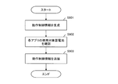
- FIG. 9 is a flowchart for explaining the operation of the control unit C3.
- the control unit C3 generates operation control information for each application (step S901). For example, the control unit C3 performs operation control information (applications AP1, AP2, and AP3 of the applications AP1, AP2, and AP3) that reflects the power demand adjustment processing content of the app for each app based on the power supply and demand adjustment processing content of each app that is grasped by the grasping unit C2.
- Step S903 Operation control information
- the control unit C3 refers to the storage unit B1 and confirms the storage batteries to be used for the applications AP1, AP2, and AP3 (step S902).
- the control unit C3 transmits the operation control information of the apps AP1, AP2, and AP3 from the communication unit C1 to the device control device R1 that is connected to the use storage battery of the apps AP1, AP2, and AP3, respectively ( Step S903).
- the control unit C3 executes steps S901 to S903 for an application whose current date and time is within the execution period, for example.
- the control unit C3 repeatedly executes steps S901 to S903 with a cycle T1.
- the controller C3 may vary the cycle T1 within a time range equal to or longer than the reference period T1s.
- the device control device R1 controls the operation of the target storage battery R3 according to the operation control information at a cycle T2 shorter than the reference period T1s.
- the appliance control device R1 may vary the cycle T2 within a time range shorter than the reference period T1s.
- the control unit C3 repeatedly transmits the operation control information at a cycle T1.
- the device control device R1 controls the operation of the use target storage battery R3 according to the operation control information at a cycle T2 shorter than the cycle T1.
- the device control device R1 can control the operation of the storage battery to be used by using the operation control information once received a plurality of times. Therefore, even if a problem occurs in communication of new operation control information, the device control device R1 can control the operation of the storage battery to be used using the received operation control information.
- selection part B3 may select the storage battery which does not satisfy the communication reliability which an application requires as a use object storage battery.
- the selection unit (acquisition unit) B3 may acquire information on the characteristics of the application, information on the battery, and the like from the storage unit as in the above embodiment, or may be acquired from an external device.
- FIG. 10 is a diagram showing a control device D according to the fourth embodiment of the present invention.
- the main difference between the fourth embodiment and the third embodiment is that, in the fourth embodiment, as the characteristics of the applications AP1 to AP3, the profitability of each application in addition to the response time and communication reliability of each application. Is used.
- the profitability of the app when the target storage battery is used for the implementation of the app, the consideration paid to the user (customer) of the target storage battery is used.
- the difference in configuration between the fourth embodiment and the third embodiment is that in the fourth embodiment, a storage unit D1 and a selection unit D3 are used instead of the storage unit B1 and the selection unit B3. .
- the fourth embodiment will be described focusing on differences from the third embodiment.
- the control device D includes a storage unit D1, a selection unit D3, a communication unit C1, a grasping unit C2, and a control unit C3.
- the selection unit D3 is an example of an acquisition unit.
- the selection unit D3, the communication unit C1, and the control unit C3 are included in the notification unit.
- the selection unit D3 functions as an acquisition unit and collects information indicating the characteristics of each application and information on each storage battery.
- the communication unit C1 and the control unit C3 function as a notification unit.
- the selection unit D3, the communication unit C1, and the control unit C3 select a storage battery as a target storage battery for each application based on the acquired information indicating the characteristics of each application and the information on each storage battery.
- the storage unit D1 is an example of a first storage unit and a second storage unit.
- the storage unit D1 simply stores information indicating the profitability of each application (hereinafter referred to as “information indicating the profitability of the application”) in addition to the response time and communication reliability of each application as the characteristics of the applications AP1 to AP3. (Also referred to as “app profitability”).
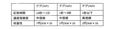
- FIG. 11 is a diagram illustrating an example of response times, communication reliability, and profitability of the applications AP1 to AP3. The response times and communication reliability of the applications AP1 to AP3 are the same as those shown in FIG.
- the profitability of app AP1 is 7 yen / kW x 1h.
- the profitability of app AP2 is 1 yen / kW x 1h.
- the profitability of app AP3 is 2 yen / kW x 1h.
- Storage unit D1 further stores the response time and the corresponding communication mode of each storage battery connected to the power system.
- the storage unit D1 further stores information indicating the revenue conditions of each of the storage batteries R3-1 to R3-n (hereinafter, “information indicating the revenue conditions” is also simply referred to as “revenue conditions”).
- the revenue condition is an example of a use condition.
- the profit condition is also an example of a consideration condition that the consideration for the use of the storage battery is a predetermined value or more.
- the profit condition is set by, for example, a consumer who is the owner of the storage battery R3.
- the profit condition may be set by a person or device different from the consumer who is the owner of the storage battery R3.
- FIG. 12 is a diagram showing an example of profit conditions for the storage batteries R3-1 to R3-n.
- the profit condition of the storage battery R3-1 is 2 yen / kW ⁇ 1h or more. 2 yen / kW ⁇ 1h is an example of a predetermined value.
- the profit condition of the storage battery R3-2 is 5 yen / kW ⁇ 1h or more. 5 yen / kW ⁇ 1h is an example of a predetermined value.
- the profit condition of the storage battery R3-n is unlimited.
- the selection unit D3 acquires information stored in the storage unit D1. For each application, the selection unit D3 selects, as a use target storage battery, a storage battery that satisfies the revenue condition among storage batteries corresponding to both the response time of the application and the communication reliability of the application. For example, it is assumed that the storage battery R3-1 corresponds to the response time and communication reliability of the application AP1. In this case, since the profitability (7 yen / kW ⁇ 1h) of the app AP1 satisfies the profit condition (2 yen / kW ⁇ 1h or more) of the storage battery R3-1, the selection unit D3 selects the storage battery R3-1 of the app AP1.
- the selection unit D3 does not select the storage battery R3-1 as the storage battery to be used for the application AP2. Further, it is assumed that the storage battery R3-1 corresponds to the response time and the communication reliability of the application AP3.
- the selection unit D3 selects the storage battery R3-1 of the app AP3. Select as the target storage battery.
- FIG. 13 is a flowchart for explaining an operation of selecting a target storage battery for each application in the present embodiment.
- the selection unit D3 refers to the storage unit D1, and for each app, the revenue condition is satisfied among the storage batteries that have a response time equal to or shorter than the app response time and have a corresponding communication mode corresponding to the communication reliability of the app.
- a storage battery is selected as a target storage battery (step S1301).
- the selection unit D3 stores the selection result in the storage unit D1 (step S1302).
- the selection unit D3 prioritizes the storage battery as a use target storage battery for the most profitable application among the plurality of applications. To choose.
- the selection unit D3 selects, as the use target storage battery, a storage battery that satisfies the revenue condition among storage batteries corresponding to both the response time of the application and the communication reliability of the application for each application. For this reason, it becomes possible to suppress selecting a storage battery that does not satisfy the profit condition as a target storage battery.
- the selection unit D3 can select one storage battery as a storage battery to be used for a plurality of applications, the single storage battery is given priority as a storage battery to be used for an application having the highest consideration for the use of the storage battery among the plurality of applications. To choose. For this reason, it becomes possible to raise the price to the consumer who has a use object storage battery.
- the selection unit (acquisition unit) D3 may acquire information on the characteristics of the application, information on the battery, and the like from the storage unit as in the above embodiment, or may be acquired from an external device.
- FIG. 14 is a diagram showing a control device E according to the fifth embodiment of the present invention.
- the same components as those shown in FIG. 10 are denoted by the same reference numerals.
- the main difference between the fifth embodiment and the fourth embodiment is that, in the fifth embodiment, the characteristics of the apps AP1 to AP3 depend on the storage battery in addition to the response time, communication reliability, and profitability of each app.
- Information indicating the reliability of the execution of the application and information indicating the execution time are used.
- “information indicating implementation reliability” is also simply referred to as “implementation reliability”.
- the “information indicating the execution time” is also simply referred to as “execution time”.
- “implementation guarantee” and “execution non-guarantee” are used as reliability.
- the execution guarantee means that the application needs to guarantee the execution of the application by the storage battery to be used.
- Implementation non-guaranteed means that the application does not require guarantee of the implementation of the application by the target storage battery.
- the difference in configuration between the fifth embodiment and the fourth embodiment is that, in the fifth embodiment, a storage unit E1 and a selection unit E3 are used instead of the storage unit D1 and the selection unit D3.
- the fifth embodiment will be described focusing on differences from the fourth embodiment.
- the control device E includes a storage unit E1, a selection unit E3, a communication unit C1, a grasping unit C2, and a control unit C3.
- the selection unit E3 is an example of an acquisition unit.
- the selection unit E3, the communication unit C1, and the control unit C3 are included in the notification unit.
- the selection unit E3 functions as an acquisition unit and collects information indicating the characteristics of each application and information on each storage battery.
- the communication unit C1 and the control unit C3 function as a notification unit.
- the selection unit E3, the communication unit C1, and the control unit C3 select a storage battery as a target storage battery for each application based on the acquired information indicating the characteristics of each application and the information on each storage battery.
- the storage unit E1 is an example of a first storage unit and a second storage unit.
- the storage unit E1 stores the reliability (implementation guarantee, implementation non-guarantee) and execution time of each application in addition to the response time, communication reliability, and profitability of each application as the characteristics of the applications AP1 to AP3.
- FIG. 15 is a diagram illustrating an example of response times, communication reliability, profitability, reliability, and execution time of the applications AP1 to AP3.
- the response times, communication reliability, and profitability of the apps AP1 to AP3 are the same as those shown in FIG.
- the reliability and execution time of the app AP1 are non-guaranteed and 3 hours (12:00 to 15:00), respectively.
- the reliability and execution time of the app AP2 are 2 hours (11-13 o'clock), guaranteeing the execution, respectively.
- the reliability and execution time of app AP3 are 6 hours (9-15 o'clock), not guaranteed.
- the storage unit E1 further stores the response time, the corresponding communication mode, and the revenue condition of each of the storage batteries R3-1 to R3-n.
- the storage unit E1 further stores information indicating the guarantee performance and the allowable usage period of each of the storage batteries R3-1 to R3-n.
- “information indicating performance assurance” is also simply referred to as “performance assurance”.
- the implementation guarantee property is an example of an implementation guarantee condition regarding the guarantee of the implementation of the application by the storage battery.
- the allowable use period is an example of a use period condition.
- the implementation guarantee property and the allowable use period are set by, for example, a consumer who is the owner of the storage battery R3.
- implementation guarantee property and implementation permissible period may be set by a person or apparatus different from the consumer who is the owner of the storage battery R3.
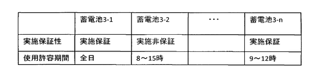
- FIG. 16 is a diagram showing an example of the performance assurance and the allowable use period of the storage batteries R3-1 to R3-n.
- the performance guarantee and use allowable period of the storage battery R3-1 are the performance guarantee and the entire day, respectively.
- the performance guarantee and use allowable period of the storage battery R3-2 are non-guaranteed and 8 to 15 o'clock, respectively.
- the performance guarantee and use allowable period of the storage battery R3-3 are the performance guarantee and 9-12 o'clock, respectively.
- the selection unit E3 acquires information stored in the storage unit E1.
- the selection unit E3 refers to the storage unit E1 and selects a storage battery that satisfies all of the following conditions (a) to (e) as a target storage battery for each application.
- Condition (d) An implementation guarantee that satisfies the reliability of the application is provided.
- the implementation guarantees that satisfy the application reliability “non-guaranteed” are “execution guarantee” and “execution non-guaranteed”, and the implementation guarantee that satisfies the app reliability “execution guarantee” is “Implementation Guarantee”.
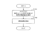
- FIG. 17 is a flowchart for explaining an operation of selecting a target storage battery for each app in the present embodiment.
- the selection unit E3 acquires the information stored in the storage unit E1, and selects a storage battery that satisfies all of the conditions (a) to (e) as a use target storage battery for each application (step S1701).
- the selection unit E3 stores the selection result in the storage unit E1 (step S1702).
- step S1701 in a situation where one storage battery can be selected as a storage battery to be used for a plurality of apps, the selection unit E3 prioritizes the storage battery as a storage battery to be used for an app having the highest profitability among a plurality of apps. To choose.
- the selection unit E3 selects a storage battery that satisfies all of the conditions (a) to (e) as the use target storage battery for each application. For this reason, it is possible to suppress selection of a storage battery that does not satisfy any of the conditions (a) to (e) as a target storage battery.
- the selection unit (acquisition unit) E3 may acquire information on the characteristics of the application, information on the battery, and the like from the storage unit as in the above embodiment, or may be acquired from an external device.
- FIG. 18 is a diagram illustrating a control device F according to the sixth embodiment of the present invention.
- the main difference between the sixth embodiment and the fifth embodiment is that, in the sixth embodiment, processing for determining a baseline of power demand is performed for each of the applications AP1 to AP3.
- the baseline of the power demand of the app AP1 is an assumed value of the customer's power demand when the app AP1 is not executed.
- the baseline of the power demand of each of the apps AP2 and AP3 is a constant value.
- the baseline of the power demand is used, for example, to verify the implementation status of the application using the target storage battery.
- the difference in configuration between the sixth embodiment and the fifth embodiment is that, in the sixth embodiment, a control unit F3 and a device control device R1A are used instead of the control unit C3 and the device control device R1. It is.
- the sixth embodiment will be described focusing on differences from the fifth embodiment.
- the control device F includes a storage unit E1, a selection unit E3, a communication unit C1, a grasping unit C2, and a control unit F3.
- the control unit F3 has a function of determining a baseline of power demand for each of the applications AP1 to AP3 in addition to the function of the control unit C3.
- the control unit F3 uses a general averaging method, regression analysis method, and the like on the basis of the power consumption history of the consumer measured by the power meter of each consumer, and uses the app AP1 for each consumer. Determine a baseline for electricity demand.
- the control part F3 may determine the baseline of the power demand of application AP1 for every consumer using the power demand prediction of the implementation time slot
- control unit F3 calculates a value obtained by correcting the measured value of the consumer's power meter with the charge / discharge amount of the storage battery R3 immediately before the implementation of the apps AP2 and AP3, based on the power demand of the apps AP2 and AP3. Decide as a line. For example, the control unit F3 determines a value obtained by subtracting the charge / discharge amount of the storage battery R3 immediately before the execution of the apps AP2 and AP3 from the measured value of the power meter as the baseline of the power demand of the apps AP2 and AP3.
- the charge / discharge amount of the storage battery R3 immediately before the execution of the apps AP2 and AP3 means the charge / discharge amount that is executed regardless of whether or not the apps AP2 and AP3 are executed. Note that it is desirable that the storage battery R3 that executes the apps AP2 and AP3 stop charging and discharging as much as possible immediately before the execution of the apps AP2 and AP3.
- the control unit F3 may operate as follows when the power demand reduction amount is insufficient for discharging the use storage battery R3 of the application AP1.
- the control unit F3 controls the device for connecting the load control information for reducing the power consumption of the load R4 of the customer who owns the target storage battery R3 with the target storage battery R3 by a specified amount to make up for the shortage.
- the data is transmitted from the communication unit C1 to the device R1A.
- the device control apparatus R1A Upon receiving the load control information, the device control apparatus R1A reduces the power consumption of the load R4 by a specified amount.
- the load control information is an example of operation control information.
- apparatus control apparatus R1A notifies the value of the electric power meter of a consumer to the control apparatus F.
- the selection unit (acquisition unit) E3 may acquire information on the characteristics of the application, information on the battery, and the like from the storage unit as in the above embodiment, or may be acquired from an external device.
- FIG. 19 is a diagram showing a control device G according to the seventh embodiment of the present invention.
- the storage battery which can be selected as a use object storage battery of a some application is selected as a use object storage battery of each of a some application.
- the difference in configuration between the seventh embodiment and the sixth embodiment is that, in the seventh embodiment, a selection unit G3 is used instead of the selection unit E3.
- the seventh embodiment will be described focusing on differences from the sixth embodiment.
- the control device G includes a storage unit E1, a selection unit G3, a communication unit C1, a grasping unit C2, and a control unit F3.
- the selection unit G3 is an example of an acquisition unit.
- the selection unit G3, the communication unit C1, and the control unit F3 are included in the notification unit.
- the selection unit G3 functions as an acquisition unit and collects information indicating the characteristics of each application and information on each storage battery.
- the communication part C1 and the control part C3 select a storage battery as a use object storage battery for every application based on the information which shows the characteristic of each application acquired as a notification part, and the information of each storage battery.
- selection part G3 has a function of selecting a storage battery which can be selected as a use object storage battery of a plurality of applications as each use object storage battery of a plurality of applications.
- the selection unit G3 selects the storage battery R3-k that can be selected as the use target storage battery of the apps AP1 and AP2 as the use target storage battery of the app AP2 from 11 to 12:00, and the app AP1 from 12 to 15:00. Select as the target storage battery.
- the storage battery R3-k can be selected as a storage battery to be used for the apps AP1 and AP2 between 12:00 and 13:00, but the selection unit G3 selects the storage battery R3-k as a highly profitable app AP1 among the apps AP1 and AP2. As the target storage battery.
- the selection unit G3 selects the storage battery R3-k as a storage battery to be used for a different app depending on the time zone. For this reason, one storage battery can be shared by a plurality of applications.
- the selection unit (acquisition unit) G3 may acquire information on the characteristics of the application, information on the battery, and the like from the storage unit as in the above embodiment, or may be acquired from an external device.
- FIG. 20 is a diagram illustrating a control device H according to an eighth embodiment of the present invention.
- the same components as those shown in FIG. 19 are denoted by the same reference numerals.
- the main difference between the eighth embodiment and the seventh embodiment is that in the eighth embodiment, as an application (power supply / demand adjustment processing), spinning reserve (instantaneous reserve power processing) or non-spinning reserve (standby power generation processing) ) Is added.
- the spinning reserve process is a process for securing an amount of power necessary for suppressing a decrease in the system frequency when the power is turned off.
- the spinning reserve will be described.
- the storage battery corresponding to the characteristics of the spinning reserve process refers to a storage battery having a time responsiveness that can be immediately responded to when the power is turned off, for example, and a supply power that can continuously generate power.
- the non-spinning reserve process is a process for generating a state in which necessary power can be supplied within a predetermined time (for example, 30 minutes) when power is required.
- the control device H includes a storage unit E1, a selection unit H3, a communication unit C1, a grasping unit C2, and a control unit F3.
- the storage unit E1 further stores characteristics (for example, response time, communication reliability, profitability, reliability, and implementation time) of the spinning reserve process and the non-spinning reserve process.
- the selection unit H3 has the following functions in addition to the functions of the selection unit G3.
- the selection unit H3 has a function of selecting a storage battery corresponding to the characteristics of the spinning reserve process as a target storage battery of the spinning reserve process and selecting a storage battery corresponding to the characteristics of the non-spinning reserve process as a target storage battery of the non-spinning reserve process. Have.
- control part F3 transmits the operation control information for controlling the operation
- the selection unit H3 selects a storage battery corresponding to the characteristics of the spinning reserve process as a target storage battery for the spinning reserve process, and selects a storage battery corresponding to the characteristics of the non-spinning reserve process as a target storage battery for the non-spinning reserve process. Choose as. For this reason, it becomes possible to suppress selecting a storage battery that does not correspond to the characteristics of the spinning reserve process as a storage battery to be used for the spinning reserve process. In addition, it is possible to suppress selecting a storage battery that does not correspond to the characteristics of the non-spinning reserve process as a storage battery to be used for the non-spinning reserve process.
- the selection unit (acquisition unit) H3 may acquire information on the characteristics of the application, information on the battery, and the like from the storage unit as in the above embodiment, or may be acquired from an external device.
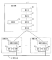
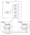
- FIG. 21 is a diagram illustrating a power control system 1000 that employs the battery control system according to the ninth embodiment of the present invention.
- the power control system 1000 includes a thermal power generator 1, a power supply command unit 2, a power system 3, a connection line 4, a distribution transformer 5, a power line 6, a centralized control device 7, and a plurality of device controls.
- Device 8, a plurality of storage batteries 9, and a plurality of loads 10 are included.
- the thermal power generator 1, the power supply command unit 2, the power system 3, the interconnection line 4, the distribution transformer 5 and the power line 6 are owned by an electric power company.
- the central control device 7 is held in the aggregator.
- the equipment control device 8, the storage battery 9, and the load 10 are held by each consumer.
- the thermal power generator 1, the distribution transformer 5 and the power line 6 are included in the power system 3.
- a renewable power source (solar power generator) 111 and a renewable power source (wind power generator) 112 are connected to the power system 3.
- the central control device 7 is an example of a control device.
- the storage battery 9 is an example of a power supply and demand adjustment device. The storage battery 9 is connected to the power system 3.
- the load 10 is, for example, a home appliance.
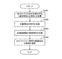
- the power supply command unit 2 transmits a request (demand) for power supply and demand adjustment processing to the centralized control device 7 on the aggregator side.
- the power supply command unit 2 transmits a plurality of types of demands to the central control device 7.
- the centralized control device 7 adjusts the power supply and demand among the storage batteries 9 held by each consumer according to the characteristics of the power supply and demand adjustment processing required for the demand for each demand (processing request) of the power company.
- the storage battery (use storage battery) to be used is selected.
- the central control device 7 creates operation control information for controlling the target storage battery 9.
- the centralized control device 7 creates operation control information reflecting the state of the storage battery to be used (for example, remaining capacity and SOC (State of Charge)) and the content of power supply and demand adjustment processing according to demand. Subsequently, the central control device 7 transmits the operation control information of the use target storage battery 9 to the device control device 8 that controls the use target storage battery 9. Transmitting the operation control information of the use target storage battery 9 to the device control apparatus 8 that controls the use target storage battery 9 is an example of a notification of activation of the power demand adjustment process.
- the device control device 8 controls the operation of the storage battery to be used according to the operation control information, and executes power supply and demand adjustment according to the demand of the power company.
- the power supply and demand adjustment according to the demand of the electric power company means a response to the demand of the electric power company (hereinafter also referred to as “response”).
- a demand reduction (for example, peak cut) request, an LFC request, and a GF request are used as the demand of the electric power company.
- the demand of the electric power company is not limited to the above and can be changed as appropriate.
- other demands of the electric power company include demand creation (for example, bottom-up) request, emergency response request, shuttable load request, supply power load request, operation reserve request, and instantaneous reserve request.
- the centralized control device 7 executes a process (hereinafter referred to as “DR application 1”) for deleting the electric power (power amount) requested by the demand reduction demand. Generate motion control information.
- the operation control information for executing the DR application 1 (demand reduction processing) is referred to as “DR application 1 operation control information”.
- the centralized control device 7 executes a process (hereinafter referred to as “DR application 2”) for controlling the operation of the storage battery to be used using an integrated value of the frequency deviation of the system frequency. Operation control information is generated.
- the operation control information for executing the DR application 2 (LFC process) is referred to as “DR application 2 operation control information”.
- the central control device 7 performs an operation for controlling the operation of the target storage battery using the frequency deviation of the system frequency (hereinafter referred to as “DR application 3”).
- DR application 3 operation control information the operation control information for executing the DR application 3 (GF processing) is referred to as “DR application 3 operation control information”.
- the thermal power generator 1 is an example of a generator.
- the power supply command unit 2 communicates with the central control device 7.
- the power supply command unit 2 transmits a demand (demand reduction request, LFC request, GF request) to the centralized control device 7.
- the power system 3 is a system that supplies power to the customer side.
- the power system 3 transforms the voltage of the generated power output from the thermal power generator 1 to a predetermined voltage by the distribution transformer 5.
- the electric power system 3 supplies electric power to the customer side with a predetermined voltage.
- the interconnection line 4 connects the power system 3 and another power system 13.
- the centralized control device 7 receives a demand (demand reduction request, LFC request, GF request) from the power supply command unit 2.
- the centralized control device 7 selects the storage battery 9 that satisfies the conditions (for example, response time and communication reliability) required by the DR application as the target storage battery for each DR application corresponding to the demand. Then, the centralized control device 7 assigns the storage battery to be used for the DR application to the DR application and the demand corresponding to the DR application.
- the condition required by the DR application means the characteristics of the DR application.
- the centralized control device 7 assigns, for each demand, a device control device 8 that controls a storage battery (usage target storage battery) 9 assigned to the demand, to the demand (DR application corresponding to the demand).
- the centralized control device 7 transmits the operation control information of the usage target storage battery 9 to the device control device 8 that controls the usage target storage battery 9 via the communication network 12.
- the device control device 8 controls the operation of the use target storage battery 9 according to the operation control information.
- FIG. 22 is a diagram illustrating an example of the power supply command unit 2, the central control device 7, and a plurality of device control devices 8.
- the storage battery 9 is built in the device control device 8, but the storage battery 9 may not be built in the device control device 8.
- the device control device 8 in which the storage battery 9 is built is an example of a power storage device.
- the device control device 8 will be described.
- the plurality of device control apparatuses 8 are allocated for each DR application corresponding to the demand and the demand.
- One device control device 8 may be allocated to a plurality of demands (DR applications corresponding to the demands).
- the device control device 8 controls the operation of the storage battery 9.
- the device control device 8 includes a detection unit 801, a communication unit 802, a frequency meter 803, and a control unit 804.
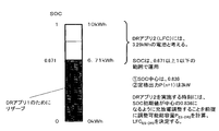
- the detection unit 801 detects the SOC of the storage battery 9.
- the SOC of the storage battery 9 takes a value within the range of 0 to 1.
- the SOC of the storage battery 9 represents the state of the storage battery 9.
- the state of the storage battery 9 is not limited to the SOC of the storage battery 9 and can be changed as appropriate.
- the communication unit 802 is an example of a communication unit and a reception unit.
- the communication unit 802 communicates with the central control device 7.
- the frequency meter 803 detects a system frequency (system frequency of the power system 3).
- the system frequency varies according to the power supply / demand balance state.
- the system frequency is an example of the state of the power system.
- the frequency meter 803 may be inside the device control device 8 or outside.
- the control unit 804 controls the charge / discharge operation of the storage battery 9 according to the operation control information.
- the control unit 804 controls the charge / discharge operation of the storage battery 9 according to the operation control information of the DR application 1.
- control unit 804 controls the charge / discharge operation of the storage battery 9 according to the operation control information of the DR applications 2 and 3 and the system frequency of the power system 3.
- the control unit 804 performs an information acquisition operation (transmission / reception process) for obtaining operation control information from the centralized control device 7 and a control operation (battery operation control process) for controlling the charge / discharge operation of the storage battery 9 using the operation control information.
- Execute The control unit 804 receives execution interval information for specifying the execution interval of control of the storage battery 9 based on the operation control information from the central control device 7 via the communication unit 802.
- the control unit 804 repeatedly executes the information acquisition operation with a time interval.
- the control unit 804 repeatedly executes the control operation at a time interval equal to or less than the time interval of the information acquisition operation according to the execution interval information.
- the centralized control device 7 places n device control devices 8 and n storage batteries 9 under management.
- the centralized control device 7 includes a selection unit 700, a communication unit 701, a database 702, a grasping unit 703, and a control unit 704.
- the selection unit 700, the communication unit 701, and the control unit 704 are included in the notification unit.
- the selection unit 700 is an example of an acquisition unit and a notification unit.
- the selection unit 700 selects, for each DR application, the storage battery 9 that satisfies the conditions required by the DR application as the use target storage battery.
- the communication unit 701 communicates with each device control device 8 and the power supply command unit 2.
- the communication unit 701 receives the SOC and ID (Identification) of the storage battery 9 from each device control device 8.
- the database 702 is an example of a first storage unit and a second storage unit.
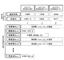
- the database 702 stores conditions required by each DR application and information on each storage battery 9. Further, the database 702 holds a storage battery distribution rate curve used for obtaining the chargeable / dischargeable capacity of the storage battery 9 from the SOC of the storage battery 9 received by the communication unit 701.
- the database 702 also holds the rated output P (n) of each storage battery 9 that is used to determine the chargeable / dischargeable capacity. As the rated output P (n) of the storage battery 9, the rated output of a power conditioner (AC / DC converter) (not shown) connected to the storage battery 9 is used.
- AC / DC converter AC / DC converter
- FIG. 23A and 23B are diagrams showing an example of a storage battery distribution rate curve.
- FIG. 23A represents an example of the storage battery distribution rate curve 202a during discharging.
- FIG. 23B shows an example of the storage battery distribution rate curve 202b during charging.
- the grasping unit 703 grasps information on each DR application.
- the information of the DR application indicates at least the processing contents of the DR application (the power supply / demand adjustment processing contents).
- the grasping unit 703 grasps the amount of power shared by the storage batteries 9 assigned to each DR application (hereinafter referred to as “DR1 shared power amount”, “DR2 shared power amount”, and “DR3 shared power amount”). To do.
- DR1 shared power amount”, “DR2 shared power amount”, and “DR3 shared power amount” are examples of the status of the power system.
- the grasping unit 703 grasps the DR2 shared power amount as follows.
- the grasping unit 703 uses the storage battery distribution rate curve in the database 702 to generate a storage battery group (DR application 2) including the storage batteries 9 assigned to the DR application 2 from the SOC of the storage battery 9 assigned to the DR application 2.
- the chargeable / dischargeable capacity of the storage battery group is derived.
- the chargeable / dischargeable capacity of the DR application 2 storage battery group is referred to as “adjustable total capacity P ES-DR2 ”.
- the grasping unit 703 transmits the adjustable total capacity P ES-DR2 from the communication unit 701 to the power supply command unit 2.
- the grasping unit 703 receives DR2 shared power amount information representing the DR2 shared power amount reflecting the adjustable total capacity P ES-DR2 from the power supply command unit 2 via the communication unit 701.
- the grasping unit 703 grasps the DR2 shared power amount using the DR2 shared power amount information.
- DR2 shared power amount information there is an LFC allocated capacity LFC ES-DR2 representing the DR2 maximum shared power amount, and a maximum value (threshold value) ⁇ f max ( ⁇ ⁇ f max ) of an integrated value of frequency deviation.
- a DR2 charge / discharge gain line is used, which represents ⁇ for simplicity.
- the “maximum value of the integrated value of the frequency deviation” is used as a threshold value of the integrated value of the deviation amount with respect to the reference frequency (for example, 50 Hz) of the system frequency.
- the reference frequency of the system frequency is stored in the control unit 804.
- the “maximum value of the integrated value of frequency deviation” means “the maximum amount of fluctuation of the integrated value of frequency deviation” that can be handled by the total output LFC ES-DR2 of the large number of storage batteries 9 assigned to the DR application 2. To do. If the integrated value of the frequency deviation is greater than or equal to the maximum value (threshold value) of the integrated value of the frequency deviation, it is difficult to cope with the LFC ES-DR2 .
- 24A is a diagram illustrating an example of a DR2 charge / discharge gain line. Details of the DR2 charge / discharge gain line will be described later.
- the control unit 704 Based on the SOC of the storage battery 9 assigned to the DR application 2 and the DR2 charge / discharge gain line, the control unit 704 obtains the DR2 sharing information (the maximum value ⁇ f max of the integrated value of the DR2 sharing coefficient K and the frequency deviation). Generate.
- the control unit 704 transmits the DR2 assignment information from the communication unit 701 to each device control apparatus 8 assigned to the DR application 2.
- the DR2 sharing coefficient K increases as the sharing ratio to the storage batteries 9 assigned to the DR application 2 increases.
- the grasping unit 703 grasps the DR3 shared power amount as follows.
- the grasping unit 703 uses the storage battery distribution rate curve in the database 702 to generate a storage battery group (DR application 3) composed of the storage batteries 9 assigned to the DR application 3 from the SOC of the storage battery 9 assigned to the DR application 3.
- the chargeable / dischargeable capacity of the storage battery group is derived.
- the storage battery distribution rate curve used here does not necessarily have to be the same as the storage battery distribution rate curve used when the amount of power shared by DR2 is derived.
- the chargeable / dischargeable capacity of the DR application 3 storage battery group is referred to as “adjustable total capacity P ES-DR3 ”.
- the grasping unit 703 transmits the adjustable total capacity P ES-DR3 from the communication unit 701 to the power supply command unit 2. Thereafter, the grasping unit 703 receives the DR3 shared power information indicating the DR3 shared power amount reflecting the adjustable total capacity P ES-DR3 from the power supply command unit 2 via the communication unit 701. The grasping unit 703 grasps the DR3 shared power amount using the DR3 shared power amount information.
- the DR3 shared power amount information the GF allocated capacity GF ES-DR3 representing the DR3 maximum shared power amount, and the maximum frequency deviation (threshold value) + f max and ⁇ f max (hereinafter, ⁇ Are collectively referred to as f max ).
- GF ES-DR3 also referred to as “LFC ES-DR3”.
- the “maximum value of frequency deviation” is used as a threshold value of the deviation amount of the system frequency with respect to a reference frequency (for example, 50 Hz).
- “Maximum value of frequency deviation” means “maximum amount of frequency deviation” that can be supported by the total output GF ES-DR3 (LFC ES-DR3 ) of a large number of storage batteries 9 assigned to DR application 3. To do. If the frequency deviation is equal to or greater than the maximum value (threshold value) of the frequency deviation, it is difficult to deal with GF ES-DR3 (LFC ES-DR3 ).
- the control unit 704 generates DR3 sharing information (DR3 sharing coefficient K and maximum frequency deviation f max ) based on the SOC of the storage battery 9 assigned to the DR application 3 and the DR3 drooping characteristic line.
- the control unit 704 transmits the DR3 assignment information from the communication unit 701 to each device control apparatus 8 assigned to the DR application 3.
- the DR3 sharing coefficient K increases as the sharing ratio to the storage batteries 9 assigned to the DR application 3 increases.
- the power supply command unit 2 includes a frequency meter 201, a communication unit 202, and a control unit 203.
- the frequency meter 201 detects the system frequency of the power system 3.
- the communication unit 202 communicates with the central control device 7.
- the communication unit 202 receives the adjustable total capacities P ES-DR2 and P ES-DR3 from the central control device 7.
- the control unit 203 controls the operation of the power supply command unit 2.
- the control unit 203 transmits various demands to the central control device 7 via the communication unit 202.
- the control unit 203 generates DR2 shared power amount information (DR2 charge / discharge gain line) and DR3 shared power amount information (DR3 drooping characteristic line) as follows.
- the control unit 203 calculates an area requirement (AR) that is an output correction amount of the power plant, using the system frequency detected by the frequency meter 201.
- the control unit 203 derives the LFC capacity using the regional requirement amount AR, the LFC adjustment capacity of the thermal power generator 1 to be controlled, and the adjustable total capacity P ES-DR2 .
- the control unit 203 obtains the LFC adjustment capacity of the thermal power generator 1 from a thermal power generator control unit (not shown).
- the adjustable total capacity P ES-DR2 is supplied from the communication unit 202 to the control unit 203.
- the control unit 203 assigns the thermal power generator 1 with a capacity obtained by removing a steep fluctuation component from the LFC capacity.
- the control unit 203 uses a high-pass filter that passes a fluctuation component having a period of 10 seconds or less in the LFC capacity and does not pass a fluctuation component having a period longer than 10 seconds, and then uses a high-pass filter from the LFC capacity (capacity LFC ES -DR2 ).
- control unit 203 allocates the LFC capacity to the thermal power generator 1 and the DR application 2 storage battery group according to a ratio (default value) for allocating the LFC capacity to the thermal power generator 1 and the DR application 2 storage battery group.
- Control unit 203 treats the capacity LFC ES-DR2 as LFC assigned capacity LFC ES-DR2.
- the control unit 203 generates a DR2 charge / discharge gain line (see FIG. 24A) representing the LFC allocated capacity LFC ES-DR2 and a predetermined maximum value (threshold value) ⁇ f max of the integrated value of the frequency deviation.
- the control unit 203 transmits a DR2 charge / discharge gain line (DR2 shared power amount information) from the communication unit 202 to the centralized control device 7.
- the control unit 203 first obtains the adjustable total capacity P ES-DR3 from the communication unit 202.
- the control unit 203 uses the predetermined maximum value (threshold value) f max of the frequency deviation and the adjustable total capacity P ES-DR3 to use the GF capacity GF ES-DR3 and DR3 for the DR application 3 storage battery group.
- a drooping characteristic line (DR3 shared energy information) is generated.
- GF ES-DR3 ⁇ P ES-DR3 .
- the control unit 203 transmits the DR3 drooping characteristic line from the communication unit 202 to the centralized control device 7.
- the control unit 203 may allocate the GF capacity to the thermal power generator 1 and the DR application 3 storage battery group according to a ratio (predetermined value) that allocates the GF capacity to the thermal power generator 1 and the DR application 3 storage battery group. In that case, the DR3 drooping characteristic line differs depending on the ratio.
- FIG. 25 illustrates the operation of the central control device 7 selecting a candidate for use storage battery to be used at the time of implementing the DR application for each of the DR applications. It is a flowchart for doing.
- the aggregator that owns the centralized control device 7 concludes a DR implementation contract with a plurality of customers that already have the storage battery 9.
- the DR implementation contract is a contract that the consumer recognizes that the aggregator controls the storage battery 9 held by the consumer as a DR on the assumption that a predetermined procedure is performed before the DR implementation.
- the DR implementation contract indicates the static characteristics (communication characteristics and responsiveness) required by each DR application and the dynamic characteristics (reliability, profitability, and implementation time) required by each DR application.
- Each DR implementation contract is stored in, for example, a contract management apparatus (not shown) owned by the aggregator. Note that the aggregator itself may determine the static characteristics required by the DR applications 1 to 3, and the contract management apparatus may store the static characteristics required by the DR applications 1 to 3 determined by the aggregator.
- the selection unit 700 collects static characteristics (communication characteristics and responsiveness) required by the DR application 1 (demand reduction process), the DR application 2 (LFC process), and the DR application 3 (GF process) ( Step S2501).
- the selection unit 700 collects “static characteristics (communication characteristics and responsiveness) required by the DR applications 1 to 3” stored in the contract management apparatus.
- a server owned by the wholesale power market stores the static characteristics required by the DR applications 1 to 3
- the selection unit 700 receives the DR application 1 from the server via the communication unit 701. You may collect the static properties that you want from ⁇ 3.
- the selection unit 700 stores the static characteristics obtained by the DR applications 1 to 3 in the database 702.
- the static characteristics required by the DR applications 1 to 3 are as follows.
- the static characteristics required by the DR applications 1 to 3 are not limited to the following.
- DR application 1 demand reduction processing
- DR application 2 LFC processing
- DR application 3 GF processing
- DR application 3 GF processing
- the selection unit 700 collects the characteristics (delay, type, rating, communication reliability, authentication result, and the like according to the corresponding communication mode) of each storage battery 9 (step S2502).
- the authentication result of the storage battery 9 means the result of the authentication organization authenticating whether the storage battery 9 satisfies the responsiveness required by the DR application. For example, when the authentication organization authenticates that the storage battery 9 satisfies the responsiveness required by the DR application 3 (GF processing), “GF authentication” is used as the authentication information of the storage battery 9.
- the selection unit 700 transmits a characteristic request from the communication unit 701 to each device control apparatus 8.
- each device control device 8 when the control unit 804 receives a characteristic request via the communication unit 802, the control unit 804 represents the battery delay, the type, the rating, the communication reliability according to the corresponding communication mode, and the authentication result for the storage battery 9.
- the characteristic parameter and the ID are transmitted to the central control device 7.
- the control unit 804 holds in advance the battery delay, type, rating, communication reliability according to the corresponding communication mode, and authentication result for the storage battery 9.
- the selection unit 700 displays the characteristic parameters (battery delay, type, rating, communication reliability according to the corresponding communication mode, authentication result) and ID transmitted from each device control device 8 in response to the characteristic request, and the communication unit 701. Accept through. Subsequently, the selection unit 700 stores the collection result of the characteristic parameters of each storage battery 9 in the database 702.
- the selection unit 700 collects the communication characteristics of the communication path used by each storage battery 9 based on the communication result regarding the transmission of the characteristic request and the reception of the characteristic parameter (step S2503).
- the selection unit 700 sets the delay time of each communication path between the central control device 7 and each device control device 8 based on the difference between the transmission timing of the characteristic request and the reception timing of the characteristic parameter. Calculated as communication delay of the communication path.
- the selection unit 700 stores the communication delay of the communication path used by each storage battery 9 in the database 702.
- the communication reliability corresponding to the corresponding communication mode is used as the communication reliability in the communication characteristics.
- the communication characteristics of the communication path used by the storage battery 9 of each consumer and the characteristics of the storage battery 9 of each consumer are as follows.
- No.1 consumer battery 9 Communication characteristics (communication reliability: high reliability, communication delay: about msec), battery characteristics (delay: about ⁇ sec, type: Lib (lithium ion battery), rating: 2kW / 6kWh, certification (Result: GF certified)
- Customer No.2 storage battery 9 Communication characteristics (communication reliability: high reliability, communication delay: about msec), battery characteristics (delay: about 10 seconds, type: lead storage battery, rating: 1kW / 3kWh, certification result: especially No authentication).
- Customer No.3 storage battery 9 communication characteristics (communication reliability: medium reliability, communication delay: about msec), battery characteristics (delay: about seconds, type: nickel metal hydride battery, rating: 3kW / 10kWh, certification result: especially No authentication).
- Customer No.4 storage battery 9 Communication characteristics (communication reliability: high reliability, communication delay: about msec), battery characteristics (delay: about ⁇ sec, type: Lib, rating: 10kW / 20kWh, certification result: GF certified ).
- Customer No.5 storage battery 9 Communication characteristics (communication reliability: high reliability, communication delay: about msec), battery characteristics (delay: about ⁇ sec, type: Lib, rating: 10kW / 10kWh, certification result: GF certified ).
- Storage battery of customer No.n 9 Communication characteristics (communication reliability: medium reliability, communication delay: about seconds), battery characteristics (delay: about several seconds, type: lead storage battery, rating: 3kW / 6kWh, certification result: especially certification None).
- the selection unit 700 stores the storage battery to be controlled by the DR application for each DR application based on the static characteristics required of the DR application stored in the database 702, the characteristics of each storage battery 9, and the communication characteristics of each communication path.
- a candidate for (use storage battery) is selected (step S2504).
- the selection unit 700 selects, for each DR application, a storage battery having characteristics corresponding to the static characteristics of the DR application as a candidate for the storage battery to be used.
- FIG. 26 is a diagram showing a candidate selection result.
- FIG. 27 shows operation for selecting use target storage battery (adjustment battery) to be actually used from candidates for use target storage battery. It is a flowchart for demonstrating.
- the selection unit 700 uses the DR application 1 (demand reduction processing), DR application 2 (LFC processing), and DR application 3 (GF processing) to determine the dynamic characteristics required by each DR application (implementation reliability, profitability, and implementation time). Are collected (step S2701).
- the selection unit 700 collects, for example, “dynamic characteristics (profitability, implementation reliability, and implementation time) required by the DR applications 1 to 3” stored in the contract management apparatus owned by the aggregator.
- the profitability is represented by, for example, “price / kW”, “kwh @ time”, and “NoN (undecided)”.
- the implementation reliability is expressed by, for example, “execution guarantee” or “execution non-guarantee”.
- the execution time is represented by, for example, “control duration” or “24-hour continuous execution”.
- the server (not shown) owned by the wholesale power market stores the dynamic characteristics required by the DR applications 1 to 3
- the selection unit 700 obtains the DR applications 1 to 3 from the server owned by the wholesale power market. Dynamic characteristics may be collected. Subsequently, the selection unit 700 stores the dynamic characteristics (implementation reliability, profitability, and implementation time) required by the DR applications 1 to 3 in the database 702.
- the aggregator itself may determine the dynamic characteristics required by the DR applications 1 to 3
- the database 702 may store the dynamic characteristics required by the DR applications 1 to 3 determined by the aggregator. In the present embodiment, it is assumed that the dynamic characteristics required by the DR applications 1 to 3 are as follows.
- DR app 1 demand reduction processing
- DR app 2 LFC processing
- DR app 3 (GF processing) is “2 yen / kW ⁇ 1h (determined value in the electric power company or wholesale power market)” as profitability, “Implementation guarantee non-guaranteed OK” as implementation reliability, and app implementation time “6 hours from 9:00 to 15:00" is required.
- the control unit 704 determines a baseline for each DR application as a reference for each consumer (storage battery) (step S2702).
- the centralized control device 7 holds the power demand history information of each customer in the database 702 in advance.
- the baseline determination method performed by the control unit 704 is the same as the method performed by the control unit F3 in the sixth embodiment. Therefore, the description of the baseline determination method performed by the control unit 704 is omitted.
- the control unit 704 may transmit the dynamic characteristics required by the DR applications 1 to 3 and the baseline used by each DR application to each device control device 8 (on the customer side).
- the central control device 7 predicts the state (available output / capacity / duration) of each storage battery 9 when the DR application is implemented, the predicted value of the power demand state, or the operation schedule information of each storage battery 9.
- the power demand schedule information of each consumer is collected (step S2703).
- each device control device 8 for example, the control unit 804 holds the operation schedule information of the storage battery 9 and the power demand schedule information of the consumer.
- the selection unit 700 collects the operation schedule information of the storage battery 9 and the power demand schedule information of the consumer from each device control device 8 (for example, the control unit 804). It is assumed that the operation schedule information of the storage battery 9 of each customer and the power demand schedule information of the customer indicate the following information.
- the operation schedule information of the storage battery 9 of each consumer and the power demand schedule information of the consumer are not limited to the following.
- the centralized control device 7 collects the consumer's willingness to participate in the DR application (implementation guarantee, profitability hope, device usage constraint) (step S2704).
- each device control apparatus 8 for example, the control unit 804 holds a consumer's intention to participate in the DR application (implementation guarantee, profitability hope, device usage constraint).
- the selection unit 700 collects the consumer's intention to participate in the DR application (implementation assurance, profitability request, device usage constraint) from each device control device 8 (for example, the control unit 804).
- each customer's willingness to participate in the DR application is as follows (see FIG. 28).
- each customer's willingness to participate in the DR application is not limited to the following.
- the selection unit 700 stores the customer's intention to participate in the DR application in the database 702.
- the centralized control device 7 determines the use target storage battery and the use target storage battery from the candidates for each DR application. Select the amount of power to be adjusted. Hereinafter, this selection method will be described.
- candidates for the storage battery to be used for each of the three DR applications this time are as follows (see FIG. 26).
- Storage battery 9 of customer No.1 candidate storage battery candidate for DR applications 1, 2 and 3
- Storage battery 9 of consumer No. 2 storage battery candidate for DR application 1
- the selection unit 700 narrows down candidates that satisfy the reliability (implementation assurance) required by the DR application, which is a necessary condition for the current DR implementation (step S2705).
- candidates are narrowed down as follows.
- Storage battery 9 of customer No.1 candidate storage battery candidate for DR applications 1, 2 and 3
- Storage battery 9 of consumer No. 2 storage battery candidate for DR application 1
- Storage battery 9 of consumer No. 3 Candidate storage battery for DR applications 1 and 2 No.4 storage battery 9: Candidate storage battery candidate for DR applications 1, 2 and 3 Storage battery 9 for consumer No.
- DR applications 1 and 2 3 candidate storage battery for use No.n storage battery 9: candidate storage battery candidate for DR application 1
- the DR application for which the implementation guarantee is requested this time is DR application 2.
- the customer who is not guaranteed is the customer No. 2.
- customer No. 2 is not a candidate for the DR application 2
- customer No. 2 is not related to the selection in step S2705.
- out of the consumers who were selected as candidates for DR application 2 among the consumers No. 6 to n-1 those who are not guaranteed are excluded from the candidates for DR application 2.
- the selection unit 700 first narrows down the target storage battery candidates for the DR application 1 with the highest profitability from the profitability provided by each DR application (step S2706).
- candidates are narrowed down as follows.
- Storage battery 9 for customer No.1 candidate storage battery for DR application 1
- Storage battery 9 for consumer No. 2 storage battery candidate for DR application 1
- Storage battery 9 for customer No. 3 DR application 1 Candidates for target storage batteries for No. 4
- Storage battery for customer No. 4 Candidates for target storage battery for DR application 1
- No. 5 storage battery for consumer No. 5 candidates for target storage battery for DR app 1 No. n for consumers
- Storage battery 9 Candidate storage battery candidates for DR application 1 At this time, all of storage batteries 9 of customers No.
- n are selected as candidate storage battery candidates for DR application 1. Further, among the storage batteries 9 of the consumers No. 6 to n-1, all the storage batteries that are candidates for the DR application 1 as a result of the narrowing down in step S2705 are selected as candidates for the DR application 1.
- the selection unit 700 selects a target storage battery for the DR application 1 based on the implementation time required by the DR application 1 (step S2707).
- the selection unit 700 determines the output of the use target storage battery of the DR application 1 so as not to exceed the available output of the use target storage battery of the DR application 1 and the available capacity.
- the selection result of the storage battery to be used by the DR application 1 and the determination result of the output are as follows. No.1 consumer battery 9: Select to apply to DR application 1 ...
- all of the storage batteries 9 of the consumers No. 1 to 5 and n are selected for application to the use target storage battery of the DR application 1.
- the storage batteries 9 of the consumers No. 1 to 5 and n are applied to the DR application 1 during the time period from 12:00 to 15:00.
- all battery candidates that can be used in the time zone in which the DR application 1 is implemented are selected to be applied to the DR application 1.
- partial time can be used in the implementation time of DR application 1 such as 12:00 to 14:00, 13:00 to 15:00, etc.
- the storage battery 9 is selected as the storage battery 9 applied to the DR application 1.
- the selection unit 700 determines whether the profitability of the DR application 1 has been determined (step S2708).
- the profitability of DR application 1 “demand reduction processing) “10 yen to 5 yen / kWh at 12:00 to 15:00” is a provisional value for bidding. For this reason, the selection unit 700 determines that the profitability of the DR application 1 is not determined.
- the reduction amount of power demand prepared at each time zone for all storage batteries of DR application 1 is ⁇ 350 kW '' from 12:00 to 13:00, ⁇ 300 kW '' from 13:00 to 14:00, and 15 from 14:00 Suppose the time was "200kW".
- the selection unit 700 participates in bidding on the wholesale power market (step S2709).
- the selection unit 700 is able to make a successful bid for a DR whose profitability is “6 yen / kWh” and the allocated amount of reduced power from 12:00 to 15:00 is “200 kW for all n customers”.
- the selection unit 700 determines the profitability and required capacity of the DR application 1 according to this successful bid (step S2710).
- the selection unit 700 allocates the 200 kW ⁇ 3 h to the storage battery of the customer selected for application to the DR application 1.
- the selection unit 700 is a method of weighting the capacity of each time zone of the storage battery 9 and determines the assignment as follows.
- the control unit 700 multiplies the capacity of each time zone of the storage battery 9 by a weighting coefficient to determine the power reduction from the baseline for each time zone as follows for the storage battery used by the DR application 1.
- Customer No.1 storage battery 9 Select to apply to DR application 1 Output: “0.5x” kW, “0.5y” kW, “0.5z” kW (each 1h)
- Customer No.2 storage battery 9 Selected for DR application 1 Output: “0.3x” kW, “0.3y” kW, “0.3z” kW (each 1h)
- Customer No.3 storage battery 9 Selected for application to DR application 1 Output: “3.0x” kW, “3.0y” kW, “3.0z” kW (each 1h)
- Customer No.5 storage battery 9 Selected for application to DR application 1 Output: "3.0x” kW, "3.0y” kW, “3.0z” kW (each 1h)
- Customer No.n storage battery 9 Selected for application to DR application 1
- the selection unit 700 determines whether or not there remains a DR application for which a use target storage battery is not selected (step S2711). When the DR application for which the use target storage battery is not selected remains, the selection unit 700 returns the process to step S2706. In the present embodiment, the selection unit 700 executes steps S2706 and S2707 for the DR application 2 and the DR application 3 as well.
- the selection unit 700 executes Step S2706 and Step S2707 for the DR application 3 (GF process) having the next highest profitability after the DR application 1.
- the implementation time of DR application 3 is from 9:00 to 15:00.
- the selection part 700 selects the use object storage battery of DR application 3 as follows.
- No.1 consumer battery 9 selected for DR application 3 (9: 00-12: 00, 1.12 kWh required after 12:00)
- Storage battery 9 for customer No. 2 Storage battery 9 of customer No.3:
- Customer No.4 storage battery 9 Storage battery 9 of customer No. 5: Selected for application to DR application 3 (9:00 to 12:00, and 6.71kWh is required after 12:00)
- Storage battery 9 of customer No.n This time, it is determined that the storage batteries 9 of the customer No.
- the selection unit 700 also applies the storage battery 9 that can be applied to the DR application 3 from 12:00 to 15:00 among the storage batteries 9 selected for the DR application 1 to the DR application 3 from 12:00 to 15:00. May be.
- the selection unit 700 does not necessarily have to leave 1.12 kWh at the 12 o'clock stage for the storage battery 9 of the customer No. 1.
- the selection unit 700 applies the storage battery 9 of the consumer No. 1 to the DR application 3 with an output of 0.62 kW obtained by dividing 1.88 kWh by 3 (3 h). In this case, the selection unit 700 applies the storage battery 9 of the customer No.
- the selection unit 700 applies the storage battery 9 of the customer No. 5 to the DR application 3 as a storage battery having an output of 0.55 kW and a capacity of 3..29 kWh.
- Step S2708 Since the profitability “2 yen / kW ⁇ 1h” of the DR application 3 is a decision value, the selection unit 700 advances the process to step S2711.
- Step S2706 and Step S2707 for the DR application 2 (LFC process) with the lowest profitability.
- Implementation time of DR application 2 is from 11:00 to 13:00.
- the selection part 700 selects the use object storage battery of DR application 2 as follows.
- No.1 storage battery 9 Storage battery 9 for customer No. 2: Storage battery 9 of customer No.3: selected for application to DR application 2 (11: 00-12: 00, 6.71kWh required after 12:00)
- all storage battery candidates that can be used in the time zone where the DR application 2 is implemented are selected to be applied to the DR application 2.
- all storage batteries 9 that can be applied to DR application 1 between 12:00 and 15:00 are applied to DR application 1
- storage batteries that can be applied to DR application 3 in the time period from 9:00 to 12:00 are All are applied to DR app 3. Therefore, DR can be used in the time zone from 11:00 to 12:00
- the storage battery 9 that is not applicable to the DR application 3 but applicable to the DR application 2 is the storage battery to be used for the DR application 2. Selected.
- the output and capacity of the storage battery 9 applied to the DR application 2 will be described.
- 10 kWh is a capacity that can be used by the storage battery 9 of the customer No. 3.
- 6.71 kWh is the capacity used by the DR application 1 for the storage battery 9 of the customer No. 3.
- the selection unit 700 regards the storage battery 9 of the customer No. 3 in the time zone of the DR application 2 as a storage battery having an SOC of 0.671 to 1.0 and a capacity of 3.29 kWh.
- the selection unit 700 prescribes the operation of the storage battery 9 so that the capacity for the DR application 1 to be executed in a later time zone remains for the other storage batteries 9 used in the DR application 2.
- FIG. 30 is a diagram illustrating a selection result of a storage battery to be used for each DR application.
- a time zone in which the storage battery cannot be applied to the DR application is indicated by a one-dot chain line.
- the consumer can use the storage battery 9 for the customer's own purpose.
- the allocated capacity to the use target storage battery group (hereinafter referred to as “use target storage battery group B”) applied to the DR application 1 (demand reduction processing) is 200 kW ⁇ 3 h (DR1 shared power amount).
- the following implementation operation of the DR application 1 is performed in the time zone from 12:00 to 15:00 with the use target storage battery group B (the number M of storage batteries 9) selected by the above process as a control target.
- FIG. 31 shows a power demand curve at the normal time of the customer No. 1.
- Consumer No. 1 has a storage battery (for example, Lib) 9 in addition to ordinary home appliances.
- Consumer No.1 is charging the storage battery 9 with cheap electricity at night, and discharging the storage battery 9 to cover the power consumption of their home appliances during the expensive electricity hours of the daytime.
- An operation was underway to reduce charges.
- consumer No. 1 did not discharge in the time zone when peak demand occurs on the power system side. Therefore, the baseline corresponding to the DR application 1 of the customer No. 1 has been recognized as the shape indicated by the solid line 31a in FIG.
- the operation control information for specifying the demand reduction amount is an example of the operation control information of the DR application 1.
- the operation control information may represent the difference from the baseline (0.29 kW from 12:00 to 13:00), or the ratio of the difference to the rated output of the power conditioner of the storage battery 9 (weighting factors: x, y, z ) May be represented.
- the DR application 1 is implemented by performing the same control for the storage batteries 9 of other customers belonging to the target storage battery group B.
- the control unit 704 of the centralized control device 7 intends to continue the execution of the DR application 1 by changing the weighting factor (x, y, z) for the storage battery of another consumer belonging to the use target storage battery group B. .
- the target storage battery group B there is a storage output capacity of 150 kW.
- the control unit 704 sets the weight coefficient for the M ⁇ 1 storage batteries to a value of “(200 kW ⁇ M) / (350 kW ⁇ (M ⁇ 1))”.
- the shortage is compensated by charging / discharging of a storage battery or the like that the aggregator holds as a reserve power.
- the central control device 7 receives the SOC of the target storage battery 9 of the DR application 2 from the device control device 8 assigned to the DR application 2 in the cycle TB1, and the SOC of the target storage battery 9 of the DR application 2 To collect.
- the period TB1 is about 15 minutes.
- the centralized control device 7 derives the adjustable total capacity P ES-DR2 based on the SOC of the usage target storage battery 9 of the DR application 2 every time the SOC of the usage target storage battery 9 of the DR application 2 is collected.
- the period Tm is equal to or greater than the period TB1, for example, 15 minutes.
- the power supply command unit 2 calculates the LFC allocated capacity LFC ES-DR2 , the power supply command unit 2 calculates the DR2 charge / discharge gain line using the LFC allocated capacity LFC ES-DR2 and the maximum value ⁇ f max of the integrated value of the frequency deviation. create.
- the power supply command unit 2 transmits the DR2 charge / discharge gain line to the centralized control device 7.
- the centralized control device 7 calculates the DR2 sharing coefficient K according to the latest DR2 charge / discharge gain line from the power supply command unit 2.
- the centralized control device 7 sends the DR2 assignment information (the maximum value ⁇ f max of the integrated value of the DR2 assignment coefficient K and the frequency deviation) to each device control device 8 assigned to the DR application 2 in the cycle TB1. Send.
- Each device control device 8 assigned to the DR application 2 performs the charging / discharging operation of the storage battery 9 to be used of the DR application 2 based on the DR2 sharing coefficient K and the maximum value ⁇ f max of the integrated value of the frequency deviation. Calculate the local charge / discharge gain line. The local charge / discharge gain line will be described later.
- Each device control device 8 assigned to the DR application 2 controls the charge / discharge operation of the storage battery 9 to be used of the DR application 2 by using the local charge / discharge gain line and the system frequency.
- P ES-DR2 derivation operation an operation in which the central control device 7 derives the adjustable total capacity P ES-DR2 based on the SOC of the storage battery 9 to be used in the DR application 2 (hereinafter referred to as “P ES-DR2 derivation operation”) will be described. .
- FIG. 32 is a sequence diagram for explaining the P ES-DR2 derivation operation.
- the number of device control devices 8 corresponding to the DR application 2 is set to 1 for the sake of simplicity of explanation.
- the communication unit 701 of the centralized control device 7 transmits an information request for requesting the SOC to each device control device 8 corresponding to the DR application 2 (step S3201).
- the control unit 804 when receiving the information request for requesting the SOC via the communication unit 802, the control unit 804 causes the detection unit 801 to detect the SOC of the storage battery 9 to be used in the DR application 2 (step S 3202). ).
- the control unit 804 transmits the SOC detected by the detection unit 801 together with the ID from the communication unit 802 to the centralized control device 7 (step S3203).
- ID is a serial number (n) from “1” to “N”.
- SOC (n) the SOC
- the central control device 7 receives the SOC (hereinafter referred to as “SOC (n)”) to which the ID is added from each device control device 8 corresponding to the DR application 2
- the central control device 7 derives the adjustable total capacity P ES-DR2 .
- Step SOC (n) the SOC
- Each device control device 8 corresponding to the central control device 7 and the DR application 2 repeats the operations of steps S3201 to S3404 (P ES-DR2 derivation operation) with a period TB1.
- the communication unit 701 of the centralized control device 7 collects SOC (n) from each device control device 8 corresponding to the DR application 2 with a period TB1. Subsequently, the grasping unit 703 uses the SOC (n) and the storage battery distribution rate curves 202a and 202b in the database 702 to store the storage battery distribution rate ⁇ discharge (n) for each use target storage battery 9 of the DR application 2. Further, the storage battery distribution rate ⁇ charge (n) at the time of charging is derived.
- the storage battery distribution rate curves 202a and 202b are based on those shown in FIGS. 23A and 23B.
- the storage battery distribution rate curves 202a and 202b are information related to the execution time required by the DR application 2 and information such as the rated output P (n) of the target storage battery 9 (what is the output of the power conditioner, Depending on how many kWh the battery capacity is, it will be a different curve.
- a curve is used in which the adjustable total capacity P ES-DR2 derived by the process described below is a value at which charging and discharging can be continued at least during the period TB1.
- the storage battery distribution rate curve is not limited to the one described here, but can be changed as appropriate according to the demand and the DR application.
- the storage battery distribution rate curves shown in FIGS. 23A and 23B curves intended to maintain SOC at about 50% at the time of charging and discharging are used. However, in order to leave the capacity for DR application 1 after DR application 2, the storage battery distribution rate curve is corrected as appropriate.
- the grasping unit 703 outputs the rated output of each of the storage batteries 9 to be used of the total number N of the DR applications 2 in the database 702, and the storage battery distribution rate ⁇ discharge (n), the storage battery distribution rate ⁇ charge (n).
- PES, discharge and PES, charge are derived using P (n) and the mathematical expressions shown in Equations 1 and 2.
- the grasping unit 703 employs the smaller value of P ES, discharge and P ES, and charge as the adjustable total capacity P ES-DR2 .
- FIG. 33 is a sequence diagram for explaining the DR2 grasping operation.
- the control unit 203 of the power supply command unit 2 calculates an area requirement (AR) that is an output correction amount of the power plant using the system frequency detected by the frequency meter 201 (step S3301). Subsequently, the control unit 203 collects the LFC adjustment capacity of the thermal power generator 1 from a thermal power generator control unit (not shown) (step S3302).
- AR area requirement
- the communication unit 701 of the centralized control device 7 transmits the latest adjustable total capacity P ES-DR2 to the power supply command unit 2 (step S3303).
- the communication unit 202 of the power supply command unit 2 receives the latest adjustable total capacity P ES-DR2 transmitted from the communication unit 701 of the central control device 7.
- the communication unit 202 outputs the latest adjustable total capacity P ES-DR2 to the control unit 203.
- the control unit 203 uses the regional requirement amount AR, the LFC adjustment capacity of the thermal power generator 1, and the latest adjustable total capacity P ES-DR2. Deriving LFC capacity.
- the control unit 203 considers the share of the EDC (Economic load dispatching control) component and also considers the economic aspect, and assigns the LFC capacity to the thermal power generator 1 and the LFC capacity to the DR application 2 storage battery group. The ratio of allocation (LFC allocation capacity LFC ES-DR ) is determined.
- the control unit 203 generates a DR2 charge / discharge gain line (see FIG. 24A) that represents the LFC allocated capacity LFC ES-DR2 and the maximum value ⁇ f max of the integral value of the predetermined frequency deviation (see FIG. 24A). S3305).
- the DR2 charge / discharge gain line shown in FIG. 24A represents the charge / discharge amount of the DR application 2 storage battery group with respect to the integral value ⁇ f of the frequency deviation.
- the control unit 203 transmits the DR2 charge / discharge gain line from the communication unit 202 to the centralized control device 7 (step S3306).
- Tm 15 minutes
- FIG. 34 is a sequence diagram for explaining the DR2 sharing operation.
- the number of device control devices 8 assigned to the DR application 2 is set to 1 for the sake of simplicity.
- the control unit 704 of the centralized control device 7 obtains the LFC allocated capacity LFC ES-DR2 indicated by the latest charge / discharge gain line, the latest adjustable total capacity P ES-DR2, and the formula shown in Equation 3. Using this, the DR2 sharing coefficient K is derived (step S3401).
- the control unit 704 sends DR2 sharing information indicating the DR2 sharing coefficient K and the maximum value ⁇ f max of the integrated value of the frequency deviation indicated by the latest DR2 charge / discharge gain line from the communication unit 701 to the DR2.
- the information is transmitted to each device control device 8 assigned to the application 2 (step S3402).
- Equation 3 is used as the DR2 sharing coefficient K.
- instructing an individual storage battery as the value of the DR2 sharing coefficient K to forcibly output an output close to the limit, etc. Flexible operation is possible.
- step S3402. For each storage battery 9 to be used in DR application 2, the control unit 704 distributes the smaller value of the latest storage battery distribution rate ⁇ discharge (n) and storage battery distribution rate ⁇ charge (n) derived by the grasping unit 703 to the storage battery distribution. It is specified as the rate ⁇ (n). Subsequently, the control unit 704 generates operation related information representing the storage battery distribution ratio ⁇ (n) and the rated output P (n) held in the database 702 for each target storage battery 9 of the DR application 2. To do. Subsequently, the control unit 704 adds DR2 assignment information to each operation related information.
- the control unit 704 transmits, from the communication unit 701, the DR2 assignment information to which the operation related information is added, to the device control apparatus 8 corresponding to the operation related information.
- the DR2 assignment information to which the operation related information is added is also an example of the operation control information of the DR application 2.
- the control unit 804 receives the DR2 sharing information with operation-related information via the communication unit 802.
- the control unit 804 derives a local charge / discharge gain coefficient G (n) using the DR2 sharing information with operation-related information and the mathematical formula shown in Equation 4 (step S3403). Note that the values in the mathematical formula 4 are shown in the DR2 assignment information with operation-related information.
- the control unit 804 uses the local charge / discharge gain coefficient G (n) and the maximum value ⁇ f max of the integrated value of the frequency deviation shown in the DR2 sharing information with operation-related information as shown in FIG.
- the local charge / discharge gain line 800A is derived (step S3404).
- the local charge / discharge gain line 800A shown in FIG. 35 is a straight line that passes through the origin 0 and has a local charge / discharge gain coefficient G (n) when the integral value ⁇ f of the frequency deviation is in the range of ⁇ f max ⁇ ⁇ f ⁇ ⁇ f max. It becomes.
- the local charge / discharge gain line 800A is referred to as “ ⁇ K ⁇ ⁇ (n) ⁇ P (n)” (the minus sign represents discharge) when the integrated value ⁇ f of the frequency deviation is in the range of ⁇ f ⁇ f max. Take a constant value.
- the local charge / discharge gain line 800A takes a constant value of “K ⁇ ⁇ (n) ⁇ P (n)” when the integrated value ⁇ f of the frequency deviation is in the range of ⁇ f max ⁇ f.
- Each device control apparatus 8 assigned to the central control apparatus 7 and the DR application 2 repeats steps S3401 to S3404 with a period TB1.
- the control unit 804 receives the DR2 sharing information with operation-related information via the communication unit 802, and the latest operation of the DR2 sharing information with operation-related information. Holds DR2 sharing information with related information.
- the device control device 8 assigned to the DR application 2 controls the charging / discharging of the storage battery 9 to be used of the DR application 2 based on the DR2 sharing information with operation related information and the system frequency (hereinafter referred to as “DR2 charging / discharging”). This will be referred to as “control operation”.
- the control unit 704 of the centralized control device 7 receives the execution interval information indicating the operation cycle TB2 from the device control device 8 assigned to the DR application 2 via the communication unit 701 when the start time of the DR application 2 is reached. Send IB.
- the operation cycle TB2 is, for example, 10 seconds.
- FIG. 36 is a sequence diagram for explaining the charge / discharge control operation.
- the control unit 804 causes the frequency meter 803 to detect the system frequency (step S3601). Subsequently, the control unit 804 calculates the integral value ⁇ f of the frequency deviation by subtracting the reference frequency of the system frequency from the detection result of the frequency meter 803 and integrating the subtraction result (step S3602).
- the control unit 804 calculates the charge amount or the discharge amount of the use storage battery 9 of the DR application 2 according to the integral value ⁇ f of the frequency deviation and the local charge / discharge gain line (step S3603).
- step S3603 when the absolute value of the integrated value ⁇ f of the frequency deviation is equal to or less than the maximum value (threshold value) ⁇ f max of the integrated value of the frequency deviation, the control unit 804 adds the frequency deviation to the local charge / discharge gain coefficient G (n).
- the absolute value of the value (G (n) ⁇ ⁇ f) multiplied by the integral value ⁇ f is calculated as the adjustment power amount.
- the control unit 804 determines the sharing coefficient K, the storage battery distribution rate ⁇ (n), and the rated output P (n).
- K the storage battery distribution rate
- P the rated output
- a value obtained by multiplying the two (K ⁇ ⁇ (n) ⁇ P (n)) is calculated as the adjustment power amount.
- G (n) the case of point symmetry in which the slope of G (n) is the same on the charge side and the discharge side is shown in FIG. 35, but actually, it is also assumed that the point is not point symmetric. In that case, G (n) is determined in the same way.
- the control unit 804 causes the use target storage battery 9 of the DR application 2 to perform the charging operation by the adjusted power amount.
- the control unit 804 causes the use target storage battery 9 of the DR application 2 to perform a discharging operation by the adjusted power amount (step S3604).
- Each device control apparatus 8 repeats steps S3601 to S3604 at the cycle TB2 indicated by the execution interval information IB. As a result, the value of the integrated value of the frequency deviation changes every time, and charging / discharging according to G (n) ⁇ ⁇ f is performed each time.
- the device control apparatus 8 (for example, the control unit 804) that executes the DR application 2 measures the charge / discharge result of the LFC with respect to the baseline.
- the device control apparatus 8 (for example, the control unit 804) that executes the DR application 2 stores the measurement result.
- the device control apparatus 8 (for example, the control unit 804) that executes the DR application 2 transmits the measurement result to the central control apparatus 7 as an execution history at an appropriate frequency.
- the central control apparatus 7 receives the SOC of the storage battery 9 to be used for the DR application 3 from the device control apparatus 8 assigned to the DR application 3 in the cycle TC1, and the SOC of the storage battery 9 to be used for the DR application 3 To collect.
- the period TC1 is about 5 minutes.
- the centralized control device 7 derives the adjustable total capacity P ES-DR3 based on the SOC of the used storage battery 9 of the DR application 3 every time the SOC of the used storage battery 9 of the DR application 3 is collected.
- the period Tm is equal to or greater than the period TC1, for example, 15 minutes.
- the power supply command unit 2 creates a DR3 drooping characteristic line using the GF allocated capacity GF ES-DR3 and the maximum value f max of the frequency deviation.
- the power supply command unit 2 transmits the DR3 drooping characteristic line to the central control device 7.
- the centralized control device 7 calculates the DR3 sharing coefficient K according to the latest DR3 drooping characteristic line from the power supply command unit 2.
- the centralized control device 7 transmits the DR3 sharing information (DR3 sharing coefficient K and the maximum frequency deviation f max ) to each device control device 8 assigned to the DR application 3 in the cycle TC1.
- Each device control device 8 assigned to the DR application 3 defines a charge / discharge operation of the storage battery 9 to be used of the DR application 3 based on the DR3 sharing coefficient K and the maximum frequency deviation f max. Calculate the droop characteristic line.
- Each device control device 8 assigned to the DR application 3 controls the charging / discharging operation of the storage battery 9 to be used of the DR application 3 by using the local drooping characteristic line and the system frequency.
- P ES-DR3 derivation operation an operation in which the central control device 7 derives the adjustable total capacity P ES-DR3 based on the SOC of the storage battery 9 to be used in the DR application 3 (hereinafter referred to as “P ES-DR3 derivation operation”) will be described.
- the description of the P ES-DR3 deriving operation is made by replacing the above description of the P ES-DR2 deriving operation as follows. Replace “DR app 2" with “DR app 3.” Replace “ DR2 ” with “ DR3 ”. Replace "cycle TB1" with "cycle TC1".
- FIG. 37 is a sequence diagram for explaining the DR3 grasping operation.
- the control unit 203 of the power supply command unit 2 calculates the required GF capacity in the region based on the predicted power generation amount of solar power generation, the predicted power generation amount of wind power generation, the power demand prediction, and the like. (Step S3701). Subsequently, the control unit 203 collects the GF adjustment capacity of the thermal power generator 1 from a thermal power generator control unit (not shown) (step S3702).
- the communication unit 701 of the centralized control device 7 transmits the latest adjustable total capacity P ES-DR3 to the power supply command unit 2 (step S3703).
- the communication unit 202 of the power supply command unit 2 receives the latest adjustable total capacity P ES-DR3 transmitted from the communication unit 701 of the central control device 7.
- the communication unit 202 outputs the latest adjustable total capacity P ES-DR3 to the control unit 203.
- the control unit 203 shares the capacity between the thermal power generator 1 and the DR application 3 storage battery group.
- the DR3 drooping characteristic line shown in FIG. 24B represents the charge / discharge amount of the DR application 3 storage battery group with respect to the frequency deviation ⁇ f.
- the control unit 203 transmits a DR3 drooping characteristic line from the communication unit 202 to the centralized control device 7 (step S3706).
- the grasping unit 703 of the centralized control device 7 receives the DR3 drooping characteristic line via the communication unit 701, and holds the latest drooping characteristic line among the DR3 drooping characteristic lines.
- FIG. 38 is a sequence diagram for explaining the DR3 sharing operation.
- the number of device control devices 8 assigned to the DR application 3 is 1 for the sake of simplicity.
- the control unit 704 of the centralized control device 7 uses the GF allocated capacity GF ES-DR3 indicated by the latest drooping characteristic line, the latest adjustable total capacity P ES-DR3, and the formula shown in Equation 5.
- the DR3 sharing coefficient K is derived (step S3801).
- the control unit 704 allocates DR3 sharing information indicating the DR3 sharing coefficient K and the maximum frequency deviation f max indicated by the latest DR3 drooping characteristic line from the communication unit 701 to the DR application 3. It transmits to each equipment control device 8 (step S3802).
- DR 5 is used as the DR3 sharing coefficient K.
- it is instructed to output an output close to the limit forcibly as a value of the DR3 sharing coefficient K, etc. Flexible operation is possible.
- step S3802. For each storage battery 9 to be used by the DR application 3, the control unit 704 distributes the smaller value of the latest storage battery distribution rate ⁇ discharge (n) and storage battery distribution rate ⁇ charge (n) derived by the grasping unit 703. It is specified as the rate ⁇ (n). Subsequently, the control unit 704 generates operation related information representing the storage battery distribution ratio ⁇ (n) and the rated output P (n) held in the database 702 for each target storage battery 9 of the DR application 3. To do. Subsequently, the control unit 704 adds DR3 assignment information to each operation related information.
- the control unit 704 transmits, from the communication unit 701, DR3 assignment information to which the operation related information is added, to the device control apparatus 8 corresponding to the operation related information.
- the DR3 sharing information to which the operation related information is added is also an example of the operation control information of the DR application 3.
- the control unit 804 receives the DR3 sharing information with operation related information via the communication unit 802.
- the control unit 804 derives a local drooping characteristic line using the maximum value f max of the frequency deviation indicated in the DR3 assignment information with motion related information and the mathematical formula shown in Equation 6 (step S3803). Note that the values in the mathematical formula 6 are shown in the DR3 assignment information with operation-related information.
- the local drooping characteristic line 400C takes a constant value of “K ⁇ ⁇ (n) ⁇ P (n)”.
- the control unit 804 receives the DR3 sharing information with operation related information via the communication unit 802, and the latest operation of the DR3 sharing information with operation related information is received. Holds DR3 sharing information with related information.
- the device controller 8 assigned to the DR application 3 controls the charging / discharging of the storage battery 9 to be used of the DR application 3 based on the DR3 sharing information with operation-related information and the system frequency (hereinafter referred to as “DR3 charging / discharging”). This will be referred to as “control operation”.
- the control unit 704 of the centralized control device 7 sends the execution interval information indicating the operation cycle TC2 to the device control device 8 assigned to the DR application 3 via the communication unit 701 when the start time of the DR application 3 comes. Send IB.
- the operation cycle TC2 is 0.1 seconds, for example.
- FIG. 39 is a sequence diagram for explaining the charge / discharge control operation.
- the control unit 804 causes the frequency meter 803 to detect the system frequency (step S3901). Subsequently, the control unit 804 calculates the frequency deviation ⁇ f by subtracting the reference frequency of the system frequency from the detection result of the frequency meter 803 (step S3902).
- the control unit 804 calculates the charge amount or the discharge amount of the use target storage battery 9 of the DR application 3 according to the frequency deviation ⁇ f and the local drooping characteristic line (step S3903).
- step S3903 when the absolute value of the frequency deviation ⁇ f is equal to or less than the maximum value (threshold value) f max of the frequency deviation, the control unit 804 multiplies GF (n) by the value obtained by dividing the frequency deviation ⁇ f by f max ( The absolute value of the GF (n) ⁇ ⁇ f / f max ) value is calculated as the adjustment power amount.
- the control unit 804 calculates GF (n) as the adjustment power amount. Subsequently, when the frequency deviation ⁇ f is a positive value, the control unit 804 causes the use target storage battery 9 of the DR application 3 to perform a charging operation by the adjusted power amount. In addition, when the frequency deviation ⁇ f is a negative value, the control unit 804 causes the use target storage battery 9 of the DR application 3 to perform a discharging operation by the adjusted power amount (step S3904).
- TC2 0.1 seconds
- the value of the frequency deviation changes every time, and charging / discharging according to GF (n) ⁇ ⁇ f / f max is performed each time.
- the selection unit 700 selects, as the use target storage battery, a storage battery corresponding to the application characteristic for each of the DR applications 1 to 3. For this reason, it becomes possible to suppress selecting the storage battery which does not respond
- the period TA1, the period TB1, the period TC1, the period TA2, the period TB2, and the period TC2 can be changed as appropriate.
- the number of DR applications performed by the central control device 7 is not limited to three and can be changed as appropriate.
- the DR application performed by the centralized control device 7 is not limited to the DR applications 1 to 3 and can be changed as appropriate.
- a spinning reserve process or a non-spinning reserve process may be used as the DR application.
- the database 702 further stores the characteristics (for example, response time, communication reliability, profitability, reliability, and implementation time) of the spinning reserve process and the non-spinning reserve process.
- the selection unit 700 further has the following functions.
- the selecting unit 700 has a function of selecting a storage battery corresponding to the characteristics of the spinning reserve process as a target storage battery for the spinning reserve process, and selecting a storage battery corresponding to the characteristics of the non-spinning reserve process as a target storage battery for the non-spinning reserve process.
- the control part 704 transmits the operation control information for controlling operation
- the control part 704 transmits the operation control information for controlling operation
- the following operation forms are also conceivable as examples of operation forms.
- reserve capacity kW
- compensation for reserve reserve for example, 1 yen / kW x 1h
- the operation of the spinning reserve process is executed in a limited time such as 11:00 to 11:30.
- the control unit 704 transmits operation control information to the equipment control device 8 of the customer No. 3 so that 3 kW is always reserved for the spinning reserve in the customer No. 3 participating in the spinning reserve process. . If the notification of new DR application 1 (demand reduction processing) comes to customer No. 3 the day before, customer No.
- a storage battery is used as the power supply / demand adjustment device, but the power supply / demand adjustment device is not limited to a storage battery.
- the power supply and demand adjustment device may be a home appliance, an electric water heater, a heat pump water heater, a pump, or an electric vehicle.
- the central control apparatus 7 collects not only the operation control information but also the information related to the monitoring of the communication state and the monitoring of the control execution state.
- the control unit 804 sets the discharge power of the storage battery 9 within the range of the power consumption of the load 10 of the consumer. To discharge. Since the load 10 consumes the discharged power of the storage battery 9, the power demand for the power system 3 is reduced. When discharge (reverse power flow) from the storage battery 9 (on the customer side) to the power system 3 is not prohibited, the control unit 804 may supply the discharge power of the storage battery 9 to the power system 3.
- the control unit 804 uses the frequency deviation f that fluctuates according to the power supply-demand balance state or the integrated value ⁇ f of the frequency deviation as information for specifying the overall supply-demand adjustment amount.
- the information for specifying the overall supply and demand adjustment amount is not limited to the frequency deviation f and the integral value ⁇ f of the frequency deviation, but can be changed as appropriate.
- information indicating the overall supply and demand adjustment amount may be used instead of the frequency deviation f and the integrated value ⁇ f of the frequency deviation.
- Information indicating the overall supply and demand adjustment amount is transmitted from, for example, the power supply command unit 2.
- the power supply command unit 2 transmits information indicating the overall supply and demand adjustment amount to each device control device 8 by, for example, one-way communication (for example, broadcast transmission).
- the transmission method of information indicating the overall supply and demand adjustment amount is not limited to one-way communication (for example, broadcast transmission), and can be changed as appropriate.
- the communication unit 802 receives information indicating the overall supply and demand adjustment amount, and outputs information indicating the overall supply and demand adjustment amount to the control unit 804.
- the control unit 804 uses the entire supply and demand adjustment amount instead of the integrated value ⁇ f of the frequency deviation, for example. In this case, the power supply / demand adjustment is explained by replacing “integrated value ⁇ f of frequency deviation” with “total supply / demand adjustment amount”.
- the power supply command unit 2 generates information indicating the overall supply and demand adjustment amount as follows.
- the power supply command unit 2 calculates the overall supply and demand adjustment amount using the system frequency and the power flow of the interconnection line 4. For example, when power is supplied from the power system 3 to another power system 13 via the interconnection line 4, the power supply command unit 2 is set to a value obtained by subtracting the actual system frequency from the reference frequency of the system frequency. Multiply the constants. Subsequently, the power supply command unit 2 subtracts the result of subtracting the power flow of the interconnection line 4 (the electric power supplied from the electric power system 3 to the other electric power system 13 via the interconnection line 4) from the multiplication result. Calculated as the overall supply and demand adjustment.
- the power supply command unit 2 when power is supplied from the other power system 13 to the power system 3 via the interconnection line 4, the power supply command unit 2 first calculates the actual system frequency from the reference frequency of the system frequency as described above. The subtracted value is multiplied by a predetermined constant. Subsequently, the power supply command unit 2 adds the result obtained by adding the power flow of the interconnection line 4 (power supplied from the other electric power system 13 to the electric power system 3 via the interconnection line 4) to the multiplication result. Calculated as the overall supply and demand adjustment.
- FIG. 41 is a diagram illustrating a device control apparatus K including an acquisition unit K1 and a notification unit K2.
- the acquisition unit K1 acquires information on the power supply / demand adjustment device shown for each power supply / demand adjustment device such as a storage battery, and information indicating the characteristics of the power supply / demand adjustment processing (application).
- the notification unit K2 uses the power supply and demand adjustment device controlled by the device control device K based on the information related to the power supply and demand adjustment device and the information indicating the characteristics of the power supply and demand adjustment processing.
- the external device is notified that it is a supply and demand adjustment device.
- the external device is, for example, the control devices A to H and the central control device 7.
- the notification of the notification unit K2 functions as a selection result of the storage battery to be used for each application. Therefore, external devices (for example, the control devices A to H and the central control device 7) do not need to select a storage battery to be used for each application, and can suppress the concentration of processing in the external device.
- the notification unit K2 may notify the external device that the power supply / demand adjustment device controlled by the device control device K is a power supply / demand adjustment device having a response time equal to or shorter than the response time of the power supply / demand adjustment process. Good.
- the notification unit K2 notifies the external device that the power supply / demand adjustment device controlled by the device control device K is a power supply / demand adjustment device having a communication reliability that is equal to or higher than the communication reliability of the power supply / demand adjustment processing. May be.
- the notification unit K2 may notify the external device that the power supply / demand adjustment device controlled by the device control device K is a power supply / demand adjustment device having a profit condition that is less than or equal to the value of the power supply / demand adjustment processing. .
- the notification unit K2 provides the power supply and demand adjustment with the most profitable power supply and demand adjustment device controlled by the device control device K.
- the external device may be notified that it is a power supply and demand adjustment device corresponding to the characteristics of the processing.
- the notification unit K2 notifies the external device that the power supply / demand adjustment device controlled by the device control device K is a power supply / demand adjustment device having a use allowable period included in the execution period related to the power supply / demand adjustment processing. Also good.
- the notification unit K2 may notify the external device that the power supply / demand adjustment device controlled by the device control device K is a power supply / demand adjustment device that satisfies the implementation guarantee related to the power supply / demand adjustment processing.
- information on the power supply and demand adjustment device is collected from a customer or a storage battery by a centralized control device (aggregator).
- a centralized control device aggregator
- information regarding the power supply and demand adjustment process (application) information collected from other devices by a central control device (aggregator), or information stored in a storage unit or a database in advance may be used.
- the selection unit (acquisition unit) 700 may acquire information about the characteristics of the application, information about the storage battery, and the like from an external device or the database 702.
- the information indicating the characteristics of the power supply and demand adjustment process such as an application is an example of information indicating a suitable condition (predetermined condition) in the execution of the power supply and demand adjustment process.
- the information related to the power supply / demand adjustment device such as a storage battery is an example of information indicating the characteristics of the power supply / demand adjustment device corresponding to a suitable condition in the execution of the power supply / demand adjustment processing such as an application.
- control devices A to H and A10, the central control device 7, and the device control devices 8 and K may each be realized by a computer.
- the computer reads and executes a program recorded on a computer-readable recording medium, and functions that any of the control devices A to H and A10, the central control device 7, and the device control devices 8 and K have.
- the recording medium is, for example, a CD-ROM (Compact Disk Read Only Memory).
- the recording medium is not limited to the CD-ROM and can be changed as appropriate.
- the illustrated configuration is merely an example, and the present invention is not limited to the configuration.
- acquisition means that the device itself obtains data or information stored in another device or a storage medium (active acquisition), for example, requests or inquires of another device.
- a control device comprising:
- a communication unit that transmits operation control information to a device control device that controls the power supply and demand adjustment device,
- the device control apparatus controls the operation of the power supply and demand adjustment apparatus based on the state of the power system and the operation control information at a time interval shorter than the transmission interval of the operation control information.
- the control device according to claim 1.
- the state of the power supply and demand adjustment device, and the amount of power shared by the N power supply and demand adjustment devices as a whole to adjust the amount of power in the power system (N is a number of 1 or more), 11.
- a communication unit that transmits information related to the power supply and demand adjustment device to an external device;
- a device control apparatus comprising: a receiving unit that receives a notification of activation of a previous power supply and demand adjustment process determined based on information relating to the power supply and demand adjustment apparatus and information indicating characteristics relating to the power supply and demand adjustment process.
- the device control device according to supplementary note 14 or 15, wherein the information related to the power supply and demand adjustment device is information indicating characteristics of the power supply and demand adjustment device corresponding to a suitable condition in the execution of the power supply and demand adjustment processing.
- a power supply and demand adjustment apparatus having a communication reliability that is equal to or higher than the communication reliability of the power supply and demand adjustment process receives a notification of the activation of the previous power supply and demand adjustment process via the receiving unit. Control device.
- the communication unit transmits the state of the power supply and demand adjustment device to the external device,
- the device control device according to any one of appendices 14 to 23, wherein the reception unit receives operation control information corresponding to a state of the power supply and demand adjustment device from the external device.
- the receiving unit is shared by N (N is a number of 1 or more) power supply and demand adjustment devices in order to adjust the state of the power supply and demand adjustment device and the amount of power in the power system.
- N is a number of 1 or more
- the device control device according to any one of appendices 14 to 23, wherein the operation control information generated based on the amount of electric power being received is received from the external device.
- the power supply and demand adjustment device is a storage battery, 28.
- the device control device according to any one of appendices 14 to 27, wherein the device control device includes the storage battery and functions as a power storage device.
- An acquisition unit that acquires information on the power supply / demand adjustment device shown for each power supply / demand adjustment device, and information indicating the characteristics of the power supply / demand adjustment processing, Notification to notify an external device that the power supply / demand adjustment device corresponds to the characteristics of the power supply / demand adjustment processing based on the information related to the power supply / demand adjustment device and information indicating the characteristics of the power supply / demand adjustment processing And a device control device.
- the device control apparatus according to supplementary note 29 or 30, wherein the information related to the power supply and demand adjustment device is information indicating characteristics of the power supply and demand adjustment device corresponding to a suitable condition in the execution of the power supply and demand adjustment processing.
- the said control part is an apparatus control apparatus of Additional remark 29 which notifies the said external device that it is an electric power supply-demand adjustment apparatus which has a response time below the response time of the said electric power supply-demand adjustment process.
- the said control part is an apparatus control apparatus of Additional remark 29 which notifies the said external device that it is an electric power supply-demand adjustment apparatus provided with the profit condition which is below the consideration of the said electric power supply-demand adjustment process.
- the said control part is an apparatus control apparatus of Additional remark 29 which notifies the said external apparatus that it is an electric power supply-demand adjustment apparatus which satisfies the implementation guarantee regarding the said electric power supply-demand adjustment process.
- the power supply and demand adjustment device is a storage battery
- the device control device according to any one of appendices 29 to 37, which includes the storage battery and functions as a power storage device.
- a notification receiving method for receiving notification of activation of a previous power supply and demand adjustment process determined based on information relating to the power supply and demand adjustment apparatus and information indicating characteristics relating to the power supply and demand adjustment process.
- a computer-readable recording medium recording a notification procedure for notification and a program for executing the notification procedure.
- a transmission procedure for transmitting information related to the power supply and demand adjustment device to an external device A recording medium for executing a reception procedure for receiving notification of activation of a previous power supply and demand adjustment process determined based on information relating to the power supply and demand adjustment apparatus and information indicating characteristics relating to the power supply and demand adjustment process.
Landscapes
- Engineering & Computer Science (AREA)
- Business, Economics & Management (AREA)
- Health & Medical Sciences (AREA)
- Power Engineering (AREA)
- Economics (AREA)
- Physics & Mathematics (AREA)
- General Physics & Mathematics (AREA)
- Water Supply & Treatment (AREA)
- Primary Health Care (AREA)
- Public Health (AREA)
- Theoretical Computer Science (AREA)
- General Health & Medical Sciences (AREA)
- Human Resources & Organizations (AREA)
- Marketing (AREA)
- Computer Networks & Wireless Communication (AREA)
- Strategic Management (AREA)
- Tourism & Hospitality (AREA)
- General Business, Economics & Management (AREA)
- Automation & Control Theory (AREA)
- Charge And Discharge Circuits For Batteries Or The Like (AREA)
- Supply And Distribution Of Alternating Current (AREA)
- Remote Monitoring And Control Of Power-Distribution Networks (AREA)
- Management, Administration, Business Operations System, And Electronic Commerce (AREA)
Abstract
Description
特許文献1に記載のDRシステムは、複数のDR契約の各々に応じた複数の調整処理(電力需要量を削減するピークカット処理や、電力系統の周波数を調整する周波数調整処理)を、1以上の電気機器の動作を制御することで実行する。
その結果、特許文献1に記載のDRシステムでは、調整処理の特性と対応しない電気機器等の電力需給調整装置を、該調整処理の実行時に使用する電力需給調整装置(使用対象装置)として選択してしまった場合、該調整処理を適切に実行できなくなってしまう。
このため、調整処理の特性と対応しない電力需給調整装置を、該調整処理の実行時に使用する電力需給調整装置(使用対象装置)として選択することを抑制可能な手法が望まれるという課題があった。
図1Aは、本発明の第1実施形態の制御装置Aを示した図である。
制御装置Aは、取得部A1と、通知部A2と、を含む。
取得部A1は、蓄電池ごとに示される蓄電池に関する情報と、電力需給調整処理の特性を示す情報と、を取得する。
本実施形態では、複数種類の電力需給調整処理として、電力需要削減処理、LFC(Load Frequency Control:負荷周波数制御)処理、GF(Governor Free:ガバナフリー)処理が用いられる。なお、複数種類の電力需給調整処理は、電力需要削減処理とLFC処理とGF処理に限らず適宜変更可能である。また、電力需給調整処理の種類数は3に限らず1以上であればよい。
以下、電力需要削減処理とLFC処理とGF処理とを、それぞれ、「アプリAP1」「アプリAP2」「アプリAP3」と称する。
アプリAP1(需要削減処理)は、例えば電力需要のピークカットを行う処理である。アプリAP2(LFC処理)およびアプリAP3(GF処理)は、電力系統の系統周波数を制御(安定化)する処理である。
アプリAP1~AP3は、いずれも、電力系統に接続された蓄電池の充電や放電を制御して電力需給調整を行う処理である。
蓄電池は、電力需給調整装置の一例である。電力需給調整装置は、蓄電池に限らず適宜変更可能である。例えば、電力需給調整装置として、電気機器や、電気温水器や、ヒートポンプ給湯器や、ポンプや、電気自動車が用いられてもよい。
取得部A1は、各アプリの特性を示す情報の一例として、各アプリが必要とする応答時間を示す情報を取得する。以下「アプリが必要とする応答時間」を「アプリの応答時間」とも称する。アプリの応答時間は、アプリが必要とする応答特性の一例である。
図2は、アプリAP1~AP3が必要とする各応答時間の一例を示した図である。
アプリAP1(需要削減処理)が必要とする応答時間は、10秒~1分である。
アプリAP2(LFC処理)が必要とする応答時間は、1秒~9秒である。
アプリAP3(GF処理)が必要とする応答時間は、1秒以下である。
取得部A1は、電力系統に接続されている各蓄電池の応答時間を示す情報を取得する。各蓄電池の応答時間を示す情報は、各蓄電池に関する情報の一例である。
ここで、応答時間について説明する。
応答時間(レスポンスタイム)とは、処理の実行指示を与えてから最初の応答までに要する時間のことをいう。
例えば、電力需給調整処理の場合は、応答時間は、「電力需要曲線の目標」に対して当該処理を行うことで電力需要曲線を一致させるのに要する時間である(例えば、アプリAP1は10秒~1分、アプリAP2は1~9秒、アプリAP3は1秒以下)。
蓄電池の場合は、応答時間は、当該処理を行うために指示を受信してから、充放電を実施するまでの時間である。
通知部A2は、各アプリの応答時間を示す情報と、各蓄電池の応答時間を示す情報と、に基づいて、アプリごとに、アプリの応答時間以下である応答時間を有する蓄電池に、該アプリの発動を通知する。アプリの応答時間以下である応答時間を有する蓄電池は、アプリの対象となる蓄電池(以下「使用対象蓄電池」とも称する)やアプリの応答時間に対応する蓄電池の一例である。使用対象蓄電池は、使用対象装置の一例である。アプリの使用対象蓄電池は、アプリ実行時に使用される蓄電池である。
図3は、制御装置Aの動作を説明するためのフローチャートである。
取得部A1は、各アプリの応答時間を示す情報と、各蓄電池の応答時間を示す情報と、を取得する(ステップS301)。
例えば、取得部A1は、各アプリの応答時間を示す情報と、各蓄電池の応答時間を示す情報とを、外部装置から取得する。なお、取得部A1は、各アプリの応答時間を示す情報と、各蓄電池の応答時間を示す情報とを、別々の外部装置から取得してもよい。
続いて、取得部A1は、各アプリの応答時間を示す情報と、各蓄電池の応答時間を示す情報とを、通知部A2に出力する。
通知部A2は、各アプリの応答時間を示す情報と、各蓄電池の応答時間を示す情報と、を受け付けると、以下のように動作する。
通知部A2は、各アプリの応答時間を示す情報と、各蓄電池の応答時間を示す情報と、を用いて、アプリごとに、アプリの応答時間以下の応答時間を有する蓄電池を使用対象蓄電池として選択する(ステップS302)。
続いて、通知部A2は、アプリごとに、使用対象蓄電池に該アプリの発動を通知する(ステップS302)。
使用対象蓄電池は、アプリの発動の通知を受信すると、該アプリの実行を開始する。
本実施形態では、取得部A1は、アプリの応答時間を示す情報と、蓄電池の応答時間を示す情報と、を取得する。通知部A2は、アプリの応答時間以下である応答時間を有する蓄電池に、該アプリの発動を通知する。
このため、アプリの応答時間よりも長い応答時間を有する蓄電池を、そのアプリの使用対象蓄電池として選択することを抑制可能になる。よって、アプリの特性に応じた蓄電池を使用対象蓄電池として選択する可能性を高くできる。アプリの特性に応じた使用対象蓄電池がアプリの実行時に使用されることで、アプリによる電力需給調整を高精度で実行することが可能になる。
アプリAP1~AP3の各応答時間は、それぞれ、10秒~1分、1秒~9秒、1秒以下に限らず適宜変更可能である。
各アプリが電力会社のデマンド(電力需給調整処理の要求)に応じたものである場合、各アプリの応答時間は、デマンドに示された必要とされる応答時間に基づいて設定されることが望ましい。
本実施形態では、アプリの特性としてアプリの応答時間が用いられたが、アプリの特性は応答時間に限らず適宜変更可能である。
通知部A2は、アプリの使用対象蓄電池を制御する機器制御装置に、該アプリに応じて使用対象蓄電池の動作を制御するための動作制御情報を送信して、該アプリの使用対象蓄電池の動作を動作制御情報に応じて制御する処理を、機器制御装置に実行させてもよい。なお、動作制御情報は、アプリの発動の通知の一例である。
図1Bは、アプリの応答時間を示す情報を格納する格納部と、蓄電池の応答時間を示す情報を格納する格納部と、を有する制御装置AAを示した図である。
制御装置AAは、格納部AA1およびAA2と、選択部AA3と、を含む。
格納部AA1は、第1格納部の一例である。格納部AA2は、第2格納部の一例である。
格納部AA1は、各アプリの特性の一例として、各アプリが必要とする応答時間を示す情報(以下「応答時間を示す情報」を、単に「応答時間」とも称する)を格納する。以下「アプリが必要とする応答時間」を「アプリの応答時間」とも称する。アプリの応答時間は、アプリが必要とする応答特性の一例である。
格納部AA2は、電力系統に接続されている各蓄電池の応答時間を示す情報を格納する。以下、「蓄電池の応答時間を示す情報」を、単に「蓄電池の応答時間」とも称する。各蓄電池の応答時間は、各蓄電池の情報の一例である。
選択部AA3は、取得部A1および通知部A2を含む。
図1Cは、取得部A1および通知部A2を含む選択部AA3と、格納部AA1およびAA2と、を含む制御装置AAを示した図である。
選択部AA3(取得部A1)は、格納部AA1に格納された各アプリの応答時間と、格納部AA2に格納された各蓄電池の応答時間と、を取得する。
選択部AA3(通知部A2)は、各アプリの応答時間と各蓄電池の応答時間と用いて、アプリごとに、アプリの応答時間以下の応答時間を有する蓄電池を使用対象蓄電池として選択する。アプリの応答時間以下の応答時間を有する蓄電池は、アプリの応答時間に対応する蓄電池の一例である。使用対象蓄電池は、使用対象装置の一例である。アプリの使用対象蓄電池は、アプリ実行時に使用される蓄電池である。
選択部AA3(通知部A2)は、アプリごとに、アプリの使用対象蓄電池に該アプリの発動を通知する。
取得部A1および通知部A2が、選択部AA3とは別に設けられている場合には、選択部AA3は、各アプリの応答時間と各蓄電池の応答時間と用いて、アプリごとに、アプリの応答時間以下の応答時間を有する蓄電池を使用対象蓄電池として選択する機能を有するものになる。
なお、本変形例および後述する実施形態において、選択部は、通知部の内部にあってもよいし、通知部とは別に設けられてもよい。また、格納部は、取得部の内部にあってもよいし、取得部とは別に設けられてもよい。
図4は、本発明の第2実施形態の制御装置Bを示した図である。
第2実施形態と第1実施形態との主な相違点は、第2実施形態では、アプリAP1~AP3の各特性として、各アプリの応答時間に加えて、各アプリが必要とする通信特性が用いられる点である。以下、第2実施形態について第1実施形態と異なる点を中心に説明する。
格納部B1は、第1格納部の一例である。格納部B1は、アプリAP1~AP3の各特性として、各アプリの応答時間に加えて、各アプリが必要とする通信特性を示す情報(以下「通信特性を示す情報」を、単に「通信特性」とも称する)を格納する。本実施形態では、通信特性として、アプリが必要とする通信信頼度(アプリが必要とする通信信頼度を示す情報)が用いられる。以下、「アプリが必要とする通信信頼度」を「アプリの通信信頼度」とも称する。
図5は、アプリAP1~AP3の応答時間および通信信頼度の一例を示した図である。
アプリAP1~AP3の応答時間は、図2に示したものと同一である。
アプリAP1およびAP2が必要とする通信信頼度は「中信頼」である。
アプリAP3が必要とする通信信頼度は「高信頼」である。
本実施形態では、通信信頼度(中信頼や高信頼)は、蓄電池側が対応している通信態様(以下「対応通信態様」)に基づいて定められる。
「高信頼」は、対応通信態様がVPN(Virtual Private Network)またはインターネットであることを意味する。なお、対応通信態様がVPNまたはインターネットである蓄電池は、VPNまたはインターネットを介して通信可能な蓄電池である。
「中信頼」は、対応通信態様が3G(3rd Generation)またはインターネットであることを意味する。なお、対応通信態様が3Gまたはインターネットである蓄電池は、3Gまたはインターネットを介して通信可能な蓄電池である。
なお、通信信頼度は、対応通信態様に基づいて定められたものに限らず適宜変更可能である。例えば、通信信頼度は、蓄電池側との通信で発生したエラー率に基づいて定められてもよい。例えば、「中信頼」と「高信頼」は、それぞれ、エラー率が第1閾値以下、エラー率が第1閾値よりも低い第2閾値以下を意味してもよい。
格納部B2は、第2格納部の一例である。格納部B2は、電力系統に接続されている各蓄電池の応答時間および対応通信態様を示す情報を格納する。以下、「蓄電池の対応通信態様を示す情報」を、単に「蓄電池の対応通信態様」とも称する。蓄電池の対応通信態様は、蓄電池の情報の一例である。
第1実施形態と同様に、選択部B3は、取得部および通知部を含んでいる。
選択部B3における取得部は、格納部B1からアプリの応答時間とアプリの通信信頼度を取得する。また、選択部B3における取得部は、格納部B2から各蓄電池の応答時間および対応通信態様を取得する。
選択部B3は、アプリの応答時間とアプリの通信信頼度と各蓄電池の応答時間および対応通信態様を参照して、アプリごとに、アプリの応答時間とアプリの通信信頼度との両方に対応する蓄電池を使用対象蓄電池として選択する。選択部B3における通知部は、アプリごとに、アプリの使用対象蓄電池に該アプリの発動を通知する。
図6は、制御装置Bの動作を説明するためのフローチャートである。
選択部B3における取得部は、アプリの応答時間とアプリの通信信頼度と各蓄電池の応答時間および対応通信態様を取得する(ステップS601)。
続いて、選択部B3は、アプリの応答時間とアプリの通信信頼度と各蓄電池の応答時間および対応通信態様に基づいて、アプリごとに、アプリの応答時間以下の応答時間を有する蓄電池の中から、アプリの通信信頼度に対応する対応通信態様を有する蓄電池を、使用対象蓄電池として選択する(ステップS602)。
ここで、選択部B3は、アプリの通信信頼度である「高信頼」に対応する対応通信態様として、VPN、インターネットを用いる。また、選択部B3は、アプリの通信信頼度である「中信頼」に対応する対応通信態様として、3G、インターネットに加えて、「高信頼」に対応するVPNも用いる。
なお、選択部B3は、アプリごとの使用対象蓄電池の選択結果を格納部B1に格納してもよい。
続いて、選択部B3における通知部は、アプリごとに、使用対象蓄電池に該アプリの発動を通知する(ステップS603)。
使用対象蓄電池は、アプリの発動の通知を受信すると、該アプリの実行を開始する。
本実施形態では、格納部B1は、各アプリが必要とする応答時間および通信信頼度を格納する。格納部B2は、電力系統に接続されている各蓄電池の応答時間および対応通信態様を格納する。選択部B3は、アプリAP1~AP3の各々について、アプリの応答時間および通信信頼度に対応する蓄電池を使用対象蓄電池として選択する。
このため、アプリが必要とする複数の特性のうち少なくともいずれかに対応しない蓄電池を、そのアプリの使用対象蓄電池として選択してしまうことを抑制可能になる。
格納部B1は、格納部B2を兼ねてもよい。この場合、格納部B1は、各アプリが必要とする応答時間および通信信頼度と、各蓄電池の応答時間および対応通信態様と、を格納する。
アプリAP1~AP3の各通信信頼度は、それぞれ、「中信頼」「中信頼」「高信頼」に限らず適宜変更可能である。
各アプリが電力会社のデマンド(電力需給調整処理の要求)に応じたものである場合、各アプリの応答時間および通信信頼度は、デマンドが要求する応答時間および通信信頼度に基づいて設定されることが望ましい。
選択部B3は、アプリの使用対象蓄電池を制御する機器制御装置に、該アプリに応じて使用対象蓄電池の動作を制御するための動作制御情報を送信して、該アプリの使用対象蓄電池の動作を動作制御情報に応じて制御する処理を機器制御装置に実行させてもよい。
格納部B1と格納部B2のうち一方または両方が、選択部B3に内蔵されてもよい。例えば、格納部B1と格納部B2は、選択部B3に内蔵されたメモリでもよい。
格納部B1と格納部B2と選択部B3は、別々の装置であってもよい。また、格納部B1と格納部B2が同一の装置に内蔵され、選択部B3が他の装置に内蔵されてもよい。
選択部(取得部)B3は、アプリの特性に関する情報や電池に関する情報などを、上記実施形態のように格納部から取得してもよいし、外部装置から取得してもよい。
図7は、本発明の第3実施形態の制御装置Cを示した図である。図7において、図4に示したものと同一構成のものには同一符号を付してある。
第3実施形態と第2実施形態との主な相違点は、第3実施形態では、格納部B1が格納部B2を兼ね、また、アプリごとに選択された使用対象蓄電池の動作を制御するために、通信部C1と把握部C2と制御部C3が追加されている点である。以下、第3実施形態について、第2実施形態と異なる点を中心に説明する。
通信部C1は、需要家側の各機器制御装置R1と通信する。
各機器制御装置R1は、電力系統R2に接続された蓄電池R3の動作(充電および放電)を制御する。電力系統R2には負荷R4も接続されている。負荷R4は、例えは家電機器である。各需要家は、機器制御装置R1と蓄電池R3と負荷R4とを保有している。
格納部B1は、選択部B3の選択結果も格納する。
図8は、選択部B3の選択結果の一例を示した図である。
図8において、「3」(「3」は蓄電池R3を意味する)に付加されたサフィックスは、蓄電池R3のID(Identification)を表す。
把握部C2は、各アプリの情報を把握する。アプリの情報は、少なくともアプリの処理内容(電力需給調整の内容)を示す。
制御部C3は、把握部C2が把握している各アプリの情報を用いて、アプリごとに、アプリの使用対象蓄電池を制御するための動作制御情報を生成する。以下、アプリAP1、AP2、AP3に応じた動作制御情報を、それぞれ、「アプリAP1の動作制御情報」「アプリAP2の動作制御情報」「アプリAP3の動作制御情報」とも称する。
アプリAP1の動作制御情報は、ピークカット(需要削減)処理用の動作制御情報である。アプリAP1の動作制御情報は、例えば、削減対象の電力量を示す動作制御情報である。
アプリAP2の動作制御情報は、LFC用の動作制御情報である。アプリAP2の動作制御情報は、電力系統R2の系統周波数の周波数偏差(基準周波数からの偏差)の積分値に基づいて使用対象蓄電池の動作を制御する処理を規定した動作制御情報である。
アプリAP3の動作制御情報は、GF用の動作制御情報である。アプリAP3の動作制御情報は、電力系統R2の系統周波数の周波数偏差に基づいて使用対象蓄電池の動作を制御する処理を規定した動作制御情報である。
制御部C3は、アプリAP1、AP2、AP3の各動作制御情報を、それぞれ、アプリAP1、AP2、AP3の使用対象蓄電池とそれぞれ接続された機器制御装置R1に、時間間隔をあけて繰り返し通信部C1から送信する。
機器制御装置R1は、動作制御情報を受信すると、動作制御情報の受信間隔以下の時間間隔(例えば、受信間隔よりも短い時間間隔)で、動作制御情報に応じて使用対象蓄電池R3の動作を制御する。
機器制御装置R1は、使用対象蓄電池R3(需要家側)から電力系統R2への放電(逆潮流)が禁止されている場合、使用対象蓄電池R3の放電電力を需要家の負荷R4の電力消費量の範囲内で放電するようにする。負荷R4が使用対象蓄電池R3の放電電力を消費することで、電力系統R2に対する電力需要が減少する。
一方、使用対象蓄電池R3(需要家側)から電力系統R2への放電(逆潮流)が禁止されていない場合、機器制御装置R1は、使用対象蓄電池R3の放電電力を電力系統R2へ供給してもよい。
選択部B3は、上述した図6に示したステップS601およびS602を実行する。さらに、選択部B3は、選択結果を格納部B1に格納する。
制御部C3は、選択部B3がアプリごとに使用対象蓄電池を選択した後に動作する。
図9は、制御部C3の動作を説明するためのフローチャートである。
制御部C3は、アプリごとに動作制御情報を生成する(ステップS901)。
例えば、制御部C3は、把握部C2が把握する各アプリの電力需給調整処理内容に基づいて、アプリごとに、アプリの電力需要調整処理内容を反映した動作制御情報(アプリAP1、AP2、AP3の動作制御情報)を作成する。
続いて、制御部C3は、格納部B1を参照してアプリAP1、AP2、AP3の使用対象蓄電池を確認する(ステップS902)。
続いて、制御部C3は、アプリAP1、AP2、AP3の各動作制御情報を、それぞれ、アプリAP1、AP2、AP3の使用対象蓄電池とそれぞれ接続された機器制御装置R1に通信部C1から送信する(ステップS903)。
なお、アプリAP1、AP2、AP3の各々の実行期間が定められている場合には、制御部C3は、例えば、現在日時が実行期間内となっているアプリについて、ステップS901~S903を実行する。
制御部C3は、ステップS901~S903を周期T1で繰り返し実行する。制御部C3は、周期T1を、基準期間T1s以上の時間範囲内で変動してもよい。
機器制御装置R1は、動作制御情報を受信すると、基準期間T1sよりも短い周期T2で、動作制御情報に応じて使用対象蓄電池R3の動作を制御する。機器制御装置R1は、周期T2を基準期間T1sよりも短い時間範囲内で変動してもよい。
本実施形態では、制御部C3は、動作制御情報の送信を周期T1で繰り返し実行する。機器制御装置R1は、周期T1よりも短い周期T2で、動作制御情報に応じて使用対象蓄電池R3の動作を制御する。機器制御装置R1は、一度受信した動作制御情報を複数回用いて使用対象蓄電池の動作を制御することが可能である。
よって、新たな動作制御情報の通信に不具合が生じても、機器制御装置R1は、受信済みの動作制御情報を用いて、使用対象蓄電池の動作を制御することが可能になる。
したがって、本実施形態においては、アプリの通信信頼度を満たさない蓄電池が使用対象蓄電池として選択された状況で通信に不具合が生じても、使用対象蓄電池の動作を精度よく制御することが可能になる。
このため、本実施形態では、選択部B3は、アプリが必要とする通信信頼度を満たしていない蓄電池を使用対象蓄電池として選択してもよい。
選択部(取得部)B3は、アプリの特性に関する情報や電池に関する情報などを、上記実施形態のように格納部から取得してもよいし、外部装置から取得してもよい。
図10は、本発明の第4実施形態の制御装置Dを示した図である。図10において、図7に示したものと同一構成のものには同一符号を付してある。
第4実施形態と第3実施形態との主な相違点は、第4実施形態では、アプリAP1~AP3の各特性として、各アプリの応答時間および通信信頼性に加えて、各アプリの収益性が用いられる点である。
本実施形態では、アプリの収益性として、アプリの実施に使用対象蓄電池が用いられた際に、その使用対象蓄電池のユーザ(需要家)に支払われる対価が用いられる。
また、第4実施形態と第3実施形態との構成上の相違点は、第4実施形態では、格納部B1と選択部B3の代わりに、格納部D1と選択部D3が用いられる点である。
以下、第4実施形態について、第3実施形態と異なる点を中心に説明する。
格納部D1は、第1格納部および第2格納部の一例である。
格納部D1は、アプリAP1~AP3の各特性として、各アプリの応答時間および通信信頼度に加えて、各アプリの収益性を示す情報(以下、「アプリの収益性を示す情報」を、単に「アプリの収益性」とも称する)を格納する。
図11は、アプリAP1~AP3の応答時間、通信信頼度および収益性の一例を示した図である。
アプリAP1~AP3の応答時間および通信信頼度は、図5に示したものと同一である。
アプリAP1の収益性は、7円/kW×1hである。
アプリAP2の収益性は、1円/kW×1hである。
アプリAP3の収益性は、2円/kW×1hである。
格納部D1は、さらに、電力系統に接続されている各蓄電池の応答時間および対応通信態様を格納する。
格納部D1は、さらに、蓄電池R3-1~R3-nの各々の収益条件を示す情報(以下、「収益条件を示す情報」を、単に「収益条件」とも称する)を格納する。
収益条件は、使用条件の一例である。収益条件は、蓄電池の使用に対する対価が所定値以上という対価条件の一例でもある。収益条件は、例えば、蓄電池R3の保有者である需要家にて設定される。なお、収益条件は、蓄電池R3の保有者である需要家とは異なる者や装置にて設定されてもよい。
図12は、蓄電池R3-1~R3-nの収益条件の一例を示した図である。
蓄電池R3-1の収益条件は、2円/kW×1h以上である。2円/kW×1hは、所定値の一例である。
蓄電池R3-2の収益条件は、5円/kW×1h以上である。5円/kW×1hは、所定値の一例である。
蓄電池R3-nの収益条件は、制限なしである。この場合、0円が所定値に対応する。
選択部D3は、格納部D1が格納している情報を取得する。
選択部D3は、アプリごとに、アプリの応答時間とアプリの通信信頼度との両方に対応する蓄電池のうち、収益条件が満たされる蓄電池を、使用対象蓄電池として選択する。
例えば、蓄電池R3-1がアプリAP1の応答時間と通信信頼度に対応しているとする。この場合、アプリAP1の収益性(7円/kW×1h)が蓄電池R3-1の収益条件(2円/kW×1h以上)を満たすので、選択部D3は、蓄電池R3-1をアプリAP1の使用対象蓄電池として選択する。
また、蓄電池R3-1がアプリAP2の応答時間と通信信頼度に対応していても、アプリAP2の収益性(1円/kW×1h)が蓄電池R3-1の収益条件(2円/kW×1h以上)を満たさない。このため、選択部D3は、蓄電池R3-1をアプリAP2の使用対象蓄電池として選択しない。
また、蓄電池R3-1がアプリAP3の応答時間と通信信頼度に対応しているとする。この場合、アプリAP3の収益性(2円/kW×1h)が蓄電池R3-1の収益条件(2円/kW×1h以上)を満たすので、選択部D3は、蓄電池R3-1をアプリAP3の使用対象蓄電池として選択する。
本実施形態の動作と第3実施形態の動作とは、アプリごとに使用対象蓄電池を選択する動作において相違する。以下では、説明の簡略化を図るため、本実施形態の動作のうち、アプリごとに使用対象蓄電池を選択する動作を説明する。
図13は、本実施形態におけるアプリごとに使用対象蓄電池を選択する動作を説明するためのフローチャートである。
選択部D3は、格納部D1を参照して、アプリごとに、アプリの応答時間以下の応答時間を有しアプリの通信信頼度に対応する対応通信態様を有する蓄電池のうち、収益条件が満たされる蓄電池を、使用対象蓄電池として選択する(ステップS1301)。
続いて、選択部D3は、選択結果を格納部D1に格納する(ステップS1302)。
なお、ステップS1301では、1つの蓄電池を複数のアプリの使用対象蓄電池として選択可能な状況では、選択部D3は、その蓄電池を、複数のアプリのうち最も収益性がよいアプリの使用対象蓄電池として優先的に選択する。
本実施形態では、選択部D3は、アプリごとに、アプリの応答時間とアプリの通信信頼度との両方に対応する蓄電池のうち収益条件が満たされる蓄電池を使用対象蓄電池として選択する。
このため、収益条件が満たされない蓄電池を、使用対象蓄電池として選択してしまうことを抑制可能になる。
また、選択部D3は、1つの蓄電池を複数のアプリの使用対象蓄電池として選択可能なときには、その1つの蓄電池を、複数のアプリのうち蓄電池の使用に対する対価が最も高いアプリの使用対象蓄電池として優先的に選択する。
このため、使用対象蓄電池を保有する需要家への対価を高くすることが可能になる。よって、蓄電池R3が使用対象蓄電池として選択されることについての需要家のモチベーションを高めることが可能になる。
選択部(取得部)D3は、アプリの特性に関する情報や電池に関する情報などを、上記実施形態のように格納部から取得してもよいし、外部装置から取得してもよい。
図14は、本発明の第5実施形態の制御装置Eを示した図である。図14において、図10に示したものと同一構成のものには同一符号を付してある。
第5実施形態と第4実施形態との主な相違点は、第5実施形態では、アプリAP1~AP3の各特性として、各アプリの応答時間、通信信頼性および収益性に加えて、蓄電池によるアプリの実施の信頼性を示す情報と、実施時間を示す情報とが用いられる点である。以下、「実施の信頼性を示す情報」を、単に「実施の信頼性」とも称する。また、「実施時間を示す情報」を、単に「実施時間」とも称する。
本実施形態では、信頼性として「実施保証」と「実施非保証」が用いられる。
実施保証は、使用対象蓄電池によるアプリの実施の保証をアプリが必要としていることを意味する。
実施非保証は、使用対象蓄電池によるアプリの実施の保証をアプリが必要としていないことを意味する。
第5実施形態と第4実施形態との構成上の相違点は、第5実施形態では、格納部D1と選択部D3の代わりに、格納部E1と選択部E3が用いられる点である。
以下、第5実施形態について、第4実施形態と異なる点を中心に説明する。
格納部E1は、第1格納部および第2格納部の一例である。
格納部E1は、アプリAP1~AP3の各特性として、各アプリの応答時間、通信信頼度および収益性に加えて、各アプリの信頼性(実施保証、実施非保証)および実施時間を格納する。
図15は、アプリAP1~AP3の応答時間、通信信頼度、収益性、信頼性および実施時間の一例を示した図である。
アプリAP1~AP3の応答時間、通信信頼度および収益性は、図11に示したものと同一である。
アプリAP1の信頼性および実施時間は、それぞれ、実施非保証、3時間(12~15時)である。
アプリAP2の信頼性および実施時間は、それぞれ、実施保証、2時間(11~13時)である。
アプリAP3の信頼性および実施時間は、それぞれ、実施非保証、6時間(9~15時)である。
格納部E1は、さらに、蓄電池R3-1~R3-nの各々の応答時間、対応通信態様および収益条件を格納する。
格納部E1は、さらに、蓄電池R3-1~R3-nの各々の実施保証性および使用許容期間を示す情報を格納する。以下、「実施保証性を示す情報」を、単に「実施保証性」とも称する。また、「使用許容期間を示す情報」を、単に「使用許容期間」とも称する。実施保証性は、蓄電池によるアプリの実施の保証に関する実施保証条件の一例である。使用許容期間は、使用期間条件の一例である。
実施保証性および使用許容期間は、例えば、蓄電池R3の保有者である需要家にて設定される。なお、実施保証性および実施許容期間は、蓄電池R3の保有者である需要家とは異なる者や装置にて設定されてもよい。
図16は、蓄電池R3-1~R3-nの実施保証性および使用許容期間の一例を示した図である。
蓄電池R3-1の実施保証性および使用許容期間は、それぞれ、実施保証、全日である。
蓄電池R3-2の実施保証性および使用許容期間は、それぞれ、実施非保証、8~15時である。
蓄電池R3-3の実施保証性および使用許容期間は、それぞれ、実施保証、9~12時である。
選択部E3は、格納部E1が格納している情報を取得する。
選択部E3は、格納部E1を参照して、アプリごとに、以下の条件(a)~(e)の全てを満たす蓄電池を、使用対象蓄電池として選択する。
条件(a):アプリの応答時間以下の応答時間を有する。
条件(b):アプリの通信信頼度に対応する対応通信態様を有する。
条件(c):アプリの収益性にて満たされる収益条件を有する。
条件(d):アプリの信頼性を満たす実施保証性を有する。
条件(e):アプリの実施時間に含まれる使用許容期間を有する。
なお、条件(d)において、アプリの信頼性「実施非保証」を満たす実施保証性は「実施保証」と「実施非保証」であり、アプリの信頼性「実施保証」を満たす実施保証性は「実施保証」である。
本実施形態の動作と第4実施形態の動作とは、アプリごとに使用対象蓄電池を選択する動作において相違する。以下では、説明の簡略化を図るため、本実施形態の動作のうち、アプリごとに使用対象蓄電池を選択する動作を説明する。
図17は、本実施形態におけるアプリごとに使用対象蓄電池を選択する動作を説明するためのフローチャートである。
選択部E3は、格納部E1が格納している情報を取得し、アプリごとに、条件(a)~(e)の全てを満たす蓄電池を使用対象蓄電池として選択する(ステップS1701)。
続いて、選択部E3は、選択結果を格納部E1に格納する(ステップS1702)。
なお、ステップS1701では、1つの蓄電池を複数のアプリの使用対象蓄電池として選択可能な状況では、選択部E3は、その蓄電池を、複数のアプリのうち最も収益性がよいアプリの使用対象蓄電池として優先的に選択する。
本実施形態では、選択部E3は、アプリごとに、条件(a)~(e)の全てを満たす蓄電池を使用対象蓄電池として選択する。このため、条件(a)~(e)のいずれかを満たさない蓄電池を使用対象蓄電池として選択してしまうことを抑制可能になる。
選択部(取得部)E3は、アプリの特性に関する情報や電池に関する情報などを、上記実施形態のように格納部から取得してもよいし、外部装置から取得してもよい。
図18は、本発明の第6実施形態の制御装置Fを示した図である。図18において、図14に示したものと同一構成のものには同一符号を付してある。
第6実施形態と第5実施形態との主な相違点は、第6実施形態では、アプリAP1~AP3の各々ついて電力需要のベースラインを決定する処理が実行される点である。
アプリAP1の電力需要のベースラインは、アプリAP1を実行しない状況での需要家の電力需要の想定値である。アプリAP2、AP3の各々の電力需要のベースラインは、一定値である。
電力需要のベースラインは、例えば、使用対象蓄電池によるアプリの実施状況を検証するために使用される。
また、第6実施形態と第5実施形態との構成上の相違点は、第6実施形態では、制御部C3と機器制御装置R1の代わりに、制御部F3と機器制御装置R1Aが用いられる点である。
以下、第6実施形態について第5実施形態と異なる点を中心に説明する。
制御部F3は、制御部C3が有する機能に加えて、アプリAP1~AP3の各々ついて電力需要のベースラインを決定する機能を有する。
例えば、制御部F3は、各需要家の電力メータで計測された需要家の電力消費の履歴に基づき、一般的な平均化法、回帰分析法などを用いて、需要家ごとに、アプリAP1の電力需要のベースラインを決定する。なお、制御部F3は、需要家ごとに、アプリAP1の実施時間帯の電力需要予測を用いてアプリAP1の電力需要のベースラインを決定してもよい。
また、制御部F3は、需要家ごとに、需要家の電力メータの計測値をアプリAP2、AP3の実施直前の蓄電池R3の充放電量で補正した値を、アプリAP2、AP3の電力需要のベースラインとして決定する。例えば、制御部F3は、電力メータの計測値からアプリAP2、AP3の実施直前の蓄電池R3の充放電量を減算した値を、アプリAP2、AP3の電力需要のベースラインとして決定する。アプリAP2、AP3の実施直前の蓄電池R3の充放電量は、アプリAP2、AP3の実施の有無に関係なく実行される充放電量を意味する。なお、アプリAP2、AP3を実施する蓄電池R3は、アプリAP2、AP3の実施直前では、できるだけ充放電を停止することが望ましい。
また、制御部F3は、アプリAP1実行時に電力需要の削減量がアプリAP1の使用対象蓄電池R3の放電では不足の場合、以下のように動作してもよい。
制御部F3は、不足量を補うための指定量の分、使用対象蓄電池R3を保有する需要家の負荷R4の電力消費を削減する旨の負荷制御情報を、使用対象蓄電池R3と接続する機器制御装置R1Aに通信部C1から送信する。
機器制御装置R1Aは、負荷制御情報を受信すると、負荷R4の電力消費を指定量削減する。負荷制御情報は、動作制御情報の一例である。
また、機器制御装置R1Aは、需要家の電力メータの値を制御装置Fに通知する。
選択部(取得部)E3は、アプリの特性に関する情報や電池に関する情報などを、上記実施形態のように格納部から取得してもよいし、外部装置から取得してもよい。
図19は、本発明の第7実施形態の制御装置Gを示した図である。図19において、図18に示したものと同一構成のものには同一符号を付してある。
第7実施形態では、複数のアプリの使用対象蓄電池として選択可能な蓄電池が、複数のアプリの各々の使用対象蓄電池として選択される。
第7実施形態と第6実施形態との構成上の相違点は、第7実施形態では、選択部E3の代わりに、選択部G3が用いられる点である。
以下、第7実施形態について第6実施形態と異なる点を中心に説明する。
選択部G3は、選択部E3が有する機能に加えて、複数のアプリの使用対象蓄電池として選択可能な蓄電池を、該複数のアプリの各々の使用対象蓄電池として選択するという機能を有する。
例えば、選択部G3は、アプリAP1およびAP2の使用対象蓄電池として選択可能な蓄電池R3-kを、11~12時まではアプリAP2の使用対象蓄電池として選択し、12~15時まではアプリAP1の使用対象蓄電池として選択する。
なお、12~13時の間、蓄電池R3-kはアプリAP1およびAP2の使用対象蓄電池として選択可能となるが、選択部G3は、蓄電池R3-kを、アプリAP1およびAP2のうち収益性の高いアプリAP1の使用対象蓄電池として選択する。
選択部(取得部)G3は、アプリの特性に関する情報や電池に関する情報などを、上記実施形態のように格納部から取得してもよいし、外部装置から取得してもよい。
図20は、本発明の第8実施形態の制御装置Hを示した図である。図20において、図19に示したものと同一構成のものには同一符号を付してある。
第8実施形態と第7実施形態との主な相違点は、第8実施形態では、アプリ(電力需給調整の処理)として、スピニングリザーブ(瞬動予備力処理)またはノンスピニングリザーブ(予備発電処理)が追加されることである。
スピニングリザーブ処理は、電源脱落時の系統周波数の低下を抑制するために必要な電力量を確保する処理である。
ここで、スピニングリザーブについて説明する。
スピニングリザーブは、電源脱落時の周波数低下に対して即時に応動を開始し、急速(10秒程度以内)に出力を上昇し、少なくとも瞬動予備力以外の運転予備力が発動されるまでの時間、継続して自動発電可能な供給力のことをいう。
このため、スピニングリザーブ処理の特性に対応する蓄電池とは、例えば上記のような電源脱落時に即時に対応できる時間応答性と、継続して発電可能な供給力を持った蓄電池のことをいう。
ノンスピニングリザーブ処理は、電力が必要になった際に所定時間(例えば30 分)以内に必要な電力を供給可能な状態を生成する処理である。
また、第8実施形態と第7実施形態との構成上の相違点は、第8実施形態では、選択部G3の代わりに、選択部H3が用いられる点である。
以下、第8実施形態について第7実施形態と異なる点を中心に説明する。
本実施形態では、格納部E1は、さらに、スピニングリザーブ処理とノンスピニングリザーブ処理の各々の特性(例えば、応答時間、通信信頼度、収益性、信頼性、実施時間)を記憶している。
選択部H3は、選択部G3が有する機能に加えて、以下の機能を有する。
選択部H3は、スピニングリザーブ処理の特性に対応する蓄電池をスピニングリザーブ処理の使用対象蓄電池として選択し、ノンスピニングリザーブ処理の特性に対応する蓄電池をノンスピニングリザーブ処理の使用対象蓄電池として選択する機能を有する。
また、本実施形態では、制御部F3は、スピニングリザーブ処理の使用対象蓄電池を制御する機器制御装置に、スピニングリザーブ処理に応じて使用対象蓄電池の動作を制御するための動作制御情報を送信する。また、制御部F3は、ノンスピニングリザーブ処理の使用対象蓄電池を制御する機器制御装置に、ノンスピニングリザーブ処理に応じて使用対象蓄電池の動作を制御するための動作制御情報を送信する。
このため、スピニングリザーブ処理の特性に対応しない蓄電池をスピニングリザーブ処理の使用対象蓄電池として選択してしまうことを抑制可能になる。また、ノンスピニングリザーブ処理の特性に対応しない蓄電池をノンスピニングリザーブ処理の使用対象蓄電池として選択してしまうことを抑制可能になる。
選択部(取得部)H3は、アプリの特性に関する情報や電池に関する情報などを、上記実施形態のように格納部から取得してもよいし、外部装置から取得してもよい。
図21は、本発明の第9実施形態の電池制御システムを採用した電力制御システム1000を示した図である。
電力制御システム1000は、火力発電機1と、給電指令部2と、電力系統3と、連系線4と、配電用変圧器5と、電力線6と、集中制御装置7と、複数の機器制御装置8と、複数の蓄電池9と、複数の負荷10と、を含む。
火力発電機1、給電指令部2、電力系統3、連系線4、配電用変圧器5および電力線6は、電力会社に保有されている。
集中制御装置7は、アグリゲータに保有されている。
機器制御装置8、蓄電池9および負荷10は、各需要家に保有されている。
火力発電機1、配電用変圧器5および電力線6は、電力系統3に含まれている。電力系統3には、再生可能電源(太陽光発電機)111と再生可能電源(風力発電機)112が接続されている。
集中制御装置7は、制御装置の一例である。蓄電池9は、電力需給調整装置の一例である。蓄電池9は、電力系統3に接続されている。負荷10は、例えば家電機器である。
電力会社側では、給電指令部2が、電力需給調整処理の要求(デマンド)を、アグリゲータ側の集中制御装置7に送信する。給電指令部2は、複数種類のデマンドを、集中制御装置7に送信する。
アグリゲータ側では、集中制御装置7は、電力会社のデマンド(処理要求)ごとに、デマンドに要求された電力需給調整処理の特性に応じて、各需要家が保有する蓄電池9の中から電力需給調整に使用する蓄電池(使用対象蓄電池)を選択する。
また、集中制御装置7は、使用対象蓄電池9を制御するための動作制御情報を作成する。
例えば、集中制御装置7は、使用対象蓄電池の状態(例えば、残り容量やSOC(State of Charge))と、デマンドに応じた電力需給調整処理の内容と、を反映した動作制御情報を作成する。
続いて、集中制御装置7は、使用対象蓄電池9を制御する機器制御装置8に対して、使用対象蓄電池9の動作制御情報を送信する。
使用対象蓄電池9を制御する機器制御装置8に対して、使用対象蓄電池9の動作制御情報を送信することは、電力需要調整処理の発動の通知の一例である。
機器制御装置8は、動作制御情報を受信すると、動作制御情報に従って使用対象蓄電池の動作を制御して、電力会社のデマンドに応じた電力需給調整を実行する。電力会社のデマンドに応じた電力需給調整は、電力会社のデマンドに対する応答(以下「レスポンス」とも称する)を意味する。
電力会社のデマンドは、上記に限らず適宜変更可能である。例えば、電力会社の他のデマンドとして、需要創出(例えば、ボトムアップ)要求、緊急時応答要求、遮断可能負荷要求、供給力負荷要求、運転予備力要求、瞬動予備力要求が挙げられる。
電力会社のデマンドがLFC要求である場合、集中制御装置7は、系統周波数の周波数偏差の積分値を用いて使用対象蓄電池の動作を制御する処理(以下「DRアプリ2」と称する)を実行するための動作制御情報を生成する。以下、DRアプリ2(LFC処理)を実行するための動作制御情報を「DRアプリ2の動作制御情報」と称する。
電力会社のデマンドがGF要求である場合、集中制御装置7は、系統周波数の周波数偏差を用いて使用対象蓄電池の動作を制御する処理(以下「DRアプリ3」と称する)を実行するための動作制御情報を生成する。以下、DRアプリ3(GF処理)を実行するための動作制御情報を「DRアプリ3の動作制御情報」と称する。
電力系統3は、電力を需要家側へ供給するシステムである。電力系統3は、火力発電機1から出力された発電電力の電圧を配電用変圧器5で所定電圧に変圧する。電力系統3は、所定電圧で電力を需要家側へ供給する。
連系線4は、電力系統3と他の電力系統13とを接続する。
集中制御装置7は、給電指令部2からデマンド(需要削減要求、LFC要求、GF要求)を受信する。
集中制御装置7は、デマンドに応じたDRアプリごとに、DRアプリが要求する条件(例えば、応答時間や通信信頼度)を満たす蓄電池9を、使用対象蓄電池として選択する。そして、集中制御装置7は、DRアプリの使用対象蓄電池を、該DRアプリと、該DRアプリに対応するデマンドと、に割り当てる。なお、DRアプリが要求する条件は、DRアプリの特性を意味する。
また、集中制御装置7は、デマンドごとに、該デマンドに割り当てられた蓄電池(使用対象蓄電池)9を制御する機器制御装置8を該デマンド(デマンドに応じたDRアプリ)に割り当てる。
集中制御装置7は、使用対象蓄電池9を制御する機器制御装置8に、使用対象蓄電池9の動作制御情報を、通信ネットワーク12を介して送信する。
機器制御装置8は、動作制御情報に応じて使用対象蓄電池9の動作を制御する。
複数の機器制御装置8は、デマンドおよびデマンドに応じたDRアプリごとに割り当てられている。なお、1台の機器制御装置8が、複数のデマンド(デマンドに応じたDRアプリ)に割り当てられていてもよい。
機器制御装置8は、蓄電池9の動作を制御する。機器制御装置8は、検出部801と、通信部802と、周波数計803と、制御部804と、を含む。
検出部801は、蓄電池9のSOCを検出する。蓄電池9のSOCは、0~1までの範囲内の値をとる。蓄電池9のSOCは、蓄電池9の状態を表す。蓄電池9の状態は、蓄電池9のSOCに限らず、適宜変更可能である。例えば、蓄電池9の状態として、蓄電池9のセル温度、電流量や電圧が用いられてもよい。
通信部802は、通信部および受信部の一例である。
通信部802は、集中制御装置7と通信する。
周波数計803は、系統周波数(電力系統3の系統周波数)を検出する。系統周波数は、電力需給バランス状態に応じて変動する。系統周波数は、電力系統の状態の一例である。周波数計803は、機器制御装置8の内部にあってもよいし、外部にあってもよい。
制御部804は、動作制御情報に応じて蓄電池9の充放電動作を制御する。例えば、制御部804は、DRアプリ1の動作制御情報に応じて、蓄電池9の充放電動作を制御する。また、制御部804は、DRアプリ2、3の動作制御情報と電力系統3の系統周波数とに応じて、蓄電池9の充放電動作を制御する。
制御部804は、集中制御装置7から動作制御情報を得る情報入手動作(送受信処理)と、動作制御情報を用いて蓄電池9の充放電動作を制御する制御動作(電池動作制御処理)と、を実行する。
制御部804は、動作制御情報に基づく蓄電池9の制御の実行間隔を特定するための実行間隔情報を、集中制御装置7から通信部802を介して受信する。
制御部804は、情報入手動作を、時間間隔をあけて繰り返し実行する。
制御部804は、実行間隔情報に従って、制御動作を情報入手動作の時間間隔以下の時間間隔をあけて繰り返し実行する。
集中制御装置7は、n台の機器制御装置8およびn個の蓄電池9を管理下に置いている。集中制御装置7は、選択部700と、通信部701と、データベース702と、把握部703と、制御部704と、を含む。選択部700と通信部701と制御部704とは、通知部に含まれる。
選択部700は、取得部および通知部の一例である。
選択部700は、DRアプリごとに、DRアプリが要求する条件を満たす蓄電池9を使用対象蓄電池として選択する。
通信部701は、各機器制御装置8および給電指令部2と通信する。例えば、通信部701は、各機器制御装置8から蓄電池9のSOCおよびID(Identification)を受信する。
データベース702は、第1格納部および第2格納部の一例である。
データベース702は、各DRアプリが要求する条件と、各蓄電池9の情報を格納する。
また、データベース702は、通信部701が受信した蓄電池9のSOCから蓄電池9の充放電可能容量を求めるために用いられる蓄電池分配率曲線を保持する。また、データベース702は、充放電可能容量を求めるために用いられる各蓄電池9の定格出力P(n)も保持する。なお、蓄電池9の定格出力P(n)としては、蓄電池9に接続された不図示のパワーコンディショナー(AC/DCコンバータ)の定格出力が用いられる。
図23A、23Bは、蓄電池分配率曲線の一例を示した図である。図23Aは、放電時の蓄電池分配率曲線202aの一例を表す。図23Bは、充電時の蓄電池分配率曲線202bの一例を表す。
把握部703は、各DRアプリの情報を把握する。DRアプリの情報は、少なくともDRアプリの処理内容(電力需給調整の処理内容)を示す。
また、把握部703は、各DRアプリに割り当てられた蓄電池9に分担されている電力量(以下、「DR1分担電力量」「DR2分担電力量」「DR3分担電力量」と称する。)を把握する。各分担電力量は、電力系統の状況の一例である。
把握部703は、データベース702内の蓄電池分配率曲線を用いて、DRアプリ2に割り当てられた蓄電池9のSOCから、DRアプリ2に割り当てられた蓄電池9にて構成される蓄電池群(DRアプリ2蓄電池群)の充放電可能容量を導出する。以下、DRアプリ2蓄電池群の充放電可能容量を「調整可能総容量PES-DR2」と称する。
把握部703は、調整可能総容量PES-DR2を通信部701から給電指令部2に送信する。その後、把握部703は、調整可能総容量PES-DR2が反映されたDR2分担電力量を表すDR2分担電力量情報を、給電指令部2から通信部701を介して受信する。把握部703は、DR2分担電力量情報を用いてDR2分担電力量を把握する。
本実施形態では、DR2分担電力量情報として、DR2最大分担電力量を表すLFC割り当て容量LFCES-DR2と、周波数偏差の積分値の最大値(閾値)Δfmax(±Δfmaxがあるが、以後簡単のため±を省略する)と、を表すDR2充放電利得線が用いられる。
“周波数偏差の積分値の最大値”は、系統周波数の基準周波数(例えば、50Hz)に対するずれ量の積分値の閾値として用いられる。系統周波数の基準周波数は、制御部804に記憶されている。
また、“周波数偏差の積分値の最大値”とは、DRアプリ2に割り当てられた多数の蓄電池9の総出力LFCES-DR2で対応できる“周波数偏差の積分値の最大の振れ量”を意味する。周波数偏差の積分値が、周波数偏差の積分値の最大値(閾値)以上の値になった場合、LFCES-DR2での対応が困難になる。
図24Aは、DR2充放電利得線の一例を示した図である。DR2充放電利得線の詳細については後述する。
制御部704は、DRアプリ2に割り当てられた蓄電池9のSOCと、DR2充放電利得線と、に基づいて、DR2分担情報(DR2分担係数Kと周波数偏差の積分値の最大値Δfmax)を生成する。制御部704は、DR2分担情報を通信部701から、DRアプリ2に割り当てられた各機器制御装置8に送信する。DR2分担係数Kは、DRアプリ2に割り当てられた蓄電池9への分担割合が高くなるほど大きくなる。
把握部703は、データベース702内の蓄電池分配率曲線を用いて、DRアプリ3に割り当てられた蓄電池9のSOCから、DRアプリ3に割り当てられた蓄電池9にて構成される蓄電池群(DRアプリ3蓄電池群)の充放電可能容量を導出する。ここで用いる蓄電池分配率曲線は、DR2の分担電力量を導出する際に用いられた蓄電池分配率曲線とは必ずしも同じでなくてもよい。以下、DRアプリ3蓄電池群の充放電可能容量を「調整可能総容量PES-DR3」と称する。
把握部703は、調整可能総容量PES-DR3を通信部701から給電指令部2に送信する。その後、把握部703は、調整可能総容量PES-DR3が反映されたDR3分担電力量を表すDR3分担電力情報を、給電指令部2から通信部701を介して受信する。把握部703は、DR3分担電力量情報を用いてDR3分担電力量を把握する。
本実施形態では、DR3分担電力量情報として、DR3最大分担電力量を表すGF割り当て容量GFES-DR3と、周波数偏差の最大値(閾値)+fmaxと- fmax(以後、簡単のため±をまとめてfmaxと称する)を表すDR3垂下特性線が用いられる。
以下、説明の都合上「GF ES-DR3」を「LFCES-DR3」とも称する。
“周波数偏差の最大値”は、系統周波数の基準周波数(例えば、50Hz)に対するずれ量の閾値として用いられる。
また、“周波数偏差の最大値”とは、DRアプリ3に割り当てられた多数の蓄電池9の総出力GF ES-DR3(LFCES-DR3)で対応できる“周波数偏差の最大の振れ量”を意味する。周波数偏差が、周波数偏差の最大値(閾値)以上の値になった場合は、GF ES-DR3(LFCES-DR3)での対応が困難になる。
図24Bは、DR3垂下特性線の一例を示した図である。DR3垂下特性線の詳細については後述する。
制御部704は、DRアプリ3に割り当てられた蓄電池9のSOCと、DR3垂下特性線と、に基づいて、DR3分担情報(DR3分担係数Kと周波数偏差の最大値fmax)を生成する。制御部704は、DR3分担情報を通信部701から、DRアプリ3に割り当てられた各機器制御装置8に送信する。DR3分担係数Kは、DRアプリ3に割り当てられた蓄電池9への分担割合が高くなるほど大きくなる。
給電指令部2は、周波数計201と、通信部202と、制御部203と、を含む。
周波数計201は、電力系統3の系統周波数を検出する。
通信部202は、集中制御装置7と通信する。
例えば、通信部202は、集中制御装置7から調整可能総容量PES-DR2、PES-DR3を受信する。
制御部203は、給電指令部2の動作を制御する。
例えば、制御部203は、通信部202を介して集中制御装置7に種々のデマンドを送信する。
また、制御部203は、以下のようにして、DR2分担電力量情報(DR2充放電利得線)と、DR3分担電力量情報(DR3垂下特性線)と、を生成する。
制御部203は、周波数計201にて検出された系統周波数を用いて、発電所の出力補正量である地域要求量(Area Requirement:AR)を計算する。制御部203は、地域要求量ARと、制御対象となる火力発電機1のLFC調整容量と、調整可能総容量PES-DR2と、を用いて、LFC容量を導出する。制御部203は、火力発電機1のLFC調整容量を不図示の火力発電機制御部から入手する、調整可能総容量PES-DR2は、通信部202から制御部203に供給される。
制御部203は、火力発電機1には、LFC容量のうち急な変動成分を除いた容量を割り当てる。制御部203は、DRアプリ2蓄電池群へは、残りのLFC容量LFCES-DR2(但し、LFCES-DR2<=PES-DR2)を割り当てる。例えば、制御部203は、LFC容量のうち周期が10秒以下の変動成分を通し周期が10秒よりも長い変動成分を通さないハイパスフィルタを用いて、LFC容量から急な変動成分(容量LFCES-DR2)を抽出する。
もしくは、制御部203は、LFC容量を火力発電機1とDRアプリ2蓄電池群とに割り振る比率(既定値)に従って、LFC容量を火力発電機1とDRアプリ2蓄電池群とに割り振る。
制御部203は、容量LFCES-DR2をLFC割り当て容量LFCES-DR2として扱う。
制御部203は、LFC割り当て容量LFCES-DR2と、予め定められた周波数偏差の積分値の最大値(閾値)Δfmaxと、を表すDR2充放電利得線(図24A参照)を生成する。
制御部203は、DR2充放電利得線(DR2分担電力量情報)を、通信部202から集中制御装置7に送信する。
電力系統の周波数偏差をある周波数偏差の範囲に収めるために必要なGF容量に関して、まず制御部203は、調整可能総容量PES-DR3を、通信部202から入手する。制御部203は、予め定められた周波数偏差の最大値(閾値)fmaxと、調整可能総容量PES-DR3と、を用いて、DRアプリ3蓄電池群へのGF容量GFES-DR3とDR3垂下特性線(DR3分担電力量情報)を生成する。但し、GFES-DR3<=PES-DR3である。制御部203は、DR3垂下特性線を通信部202から集中制御装置7に送信する。
なお、制御部203は、GF容量を火力発電機1とDRアプリ3蓄電池群とに割り振る比率(既定値)に従って、GF容量を火力発電機1とDRアプリ3蓄電池群とに割り振ってもよい。その場合は、DR3垂下特性線は、比率に応じて異なるものになる。
図25は、集中制御装置7がDRアプリの各々について、DRアプリ実施時に使用する使用対象蓄電池の候補を選定する動作を説明するためのフローチャートである。
DR実施契約は、アグリゲータがDRとして需要家が保有する蓄電池9を制御することを、DR実施前に所定の手続きを経ることを前提に、需要家が認める契約である。
DR実施契約には、各DRアプリの求める静的特性(通信特性および応答性)と、各DRアプリの求める動的特性(信頼性、収益性および実施時間)とが示されている。
各DR実施契約は、例えば、アグリゲータが保有する契約管理装置(不図示)に格納される。
なお、アグリゲータ自身がDRアプリ1~3の求める静的特性を決定し、契約管理装置が、アグリゲータの決定したDRアプリ1~3の求める静的特性を記憶してもよい。
ステップS2501では、選択部700は、例えば、契約管理装置に記憶されている「DRアプリ1~3の求める静的特性(通信特性および応答性)」を収集する。
なお、卸売電力市場が保有するサーバ(不図示)がDRアプリ1~3の求める静的特性を記憶している場合、選択部700は、通信部701を介して、該サーバから、DRアプリ1~3の求める静的特性を収集してもよい。
続いて、選択部700は、DRアプリ1~3の求める静的特性をデータベース702に格納する。
本実施形態では、DRアプリ1~3の求める静的特性が以下の通りであったとする。なお、DRアプリ1~3の求める静的特性は以下のものに限らない。
DRアプリ1(需要削減処理)は、応答性(応答時間)として「10秒~1分」、通信特性(通信信頼度)として「中信頼」を必要とする。
DRアプリ2(LFC処理)は、応答性(応答時間)として「1~9秒」、通信特性(通信信頼度)として「中信頼」を必要とする。
DRアプリ3(GF処理)は、応答性(応答時間)として「1秒以下」、通信特性(通信信頼度)として「高信頼」を必要とする。
ここで、蓄電池9の認証結果とは、DRアプリが求める応答性等を蓄電池9が満たしているかを認証機関が認証した結果を意味する。例えば、認証機関が、蓄電池9はDRアプリ3(GF処理)の求める応答性を満たしていると認証した場合、蓄電池9の認証情報として「GF認証」が用いられる。
ステップS2502では、選択部700は、通信部701から各機器制御装置8に特性要求を送信する。
各機器制御装置8では、制御部804は、通信部802を介して特性要求を受信すると、蓄電池9についての、電池遅延、種類、定格、対応通信態様に応じた通信信頼度、認証結果を表す特性パラメータと、IDとを、集中制御装置7に送信する。なお、制御部804は、蓄電池9についての、電池遅延、種類、定格、対応通信態様に応じた通信信頼度、認証結果を、あらかじめ保持している。
選択部700は、特性要求に応じて各機器制御装置8から送信された特性パラメータ(電池遅延、種類、定格、対応通信態様に応じた通信信頼度、認証結果)およびIDを、通信部701を介して受け付ける。
続いて、選択部700は、各蓄電池9の特性パラメータの収集結果を、データベース702に格納する。
ステップS2503では、選択部700は、特性要求の送信タイミングと特性パラメータの受信タイミングとの差に基づいて、集中制御装置7と各機器制御装置8との間の各通信経路の遅延時間を、各通信経路の通信遅延として算出する。
続いて、選択部700は、各蓄電池9が使用する通信経路の通信遅延をデータベース702に格納する。なお、以下では、対応通信態様に応じた通信信頼度を、通信特性における通信信頼性として用いる。
本実施形態では、各需要家の蓄電池9が使用する通信経路の通信特性と、各需要家の蓄電池9の特性が、以下の通りであったとする。
需要家No.1の蓄電池9:通信特性(通信信頼性:高信頼、通信遅延:msec程度)、電池特性(遅延:μsec程度、種類:Lib(リチウムイオン電池)、定格:2kW/6kWh、認証結果:GF認証あり)。
需要家No.2の蓄電池9:通信特性(通信信頼性:高信頼、通信遅延:msec程度)、電池特性(遅延:十数秒程度、種類:鉛蓄電池、定格:1kW/3kWh、認証結果:特に認証無し)。
需要家No.3の蓄電池9:通信特性(通信信頼性:中信頼、通信遅延:msec程度)、電池特性(遅延:秒程度、種類:ニッケル水素電池、定格:3kW/10kWh、認証結果:特に認証無し)。
需要家No.4の蓄電池9:通信特性(通信信頼性:高信頼、通信遅延:msec程度)、電池特性(遅延:μsec程度、種類:Lib、定格:10kW/20kWh、認証結果:GF認証あり)。
需要家No.5の蓄電池9:通信特性(通信信頼性:高信頼、通信遅延:msec程度)、電池特性(遅延:μsec程度、種類:Lib、定格:10kW/10kWh、認証結果:GF認証あり)。
需要家No.nの蓄電池9:通信特性(通信信頼性:中信頼、通信遅延:秒程度)、電池特性(遅延:数秒程度、種類:鉛蓄電池、定格:3kW/6kWh、認証結果:特に認証無し)。
ステップ2504では、選択部700は、DRアプリごとに、DRアプリの静的特性に該当する特性を有する蓄電池を、使用対象蓄電池の候補として選択する。
図26は、候補の選択結果を示した図である。
なお、DRアプリ1~3は、DRアプリとして存在はするが、以下で述べる処理(特にアプリ実施で得られる利益を考慮する処理)によって、実際には、各需要家が自分の蓄電池を用いて実施するDRアプリとして選ばれない可能性がある。このため、この段階では、DRアプリ1~3は、実施されるアプリケーションの候補としての位置づけである。
図27は、使用対象蓄電池の候補の中から実際に使用する使用対象蓄電池(調整用電池)を選定する動作を説明するためのフローチャートである。
ステップS2701では、選択部700は、例えば、アグリゲータが保有する契約管理装置に記憶されている「DRアプリ1~3の求める動的特性(収益性、実施信頼性および実施時間)」を収集する。
収益性は、例えば、「価格/kW」や「kwh@時刻」、「NoN(未定)」で表される。
実施信頼性は、例えば、「実施保証」や「実施非保証」で表される。
実施時間は、例えば、「制御継続時間」や「24時間連続実施」で表される。
卸売電力市場が保有するサーバ(不図示)がDRアプリ1~3の求める動的特性を記憶している場合、選択部700は、卸売電力市場が保有するサーバから、DRアプリ1~3の求める動的特性を収集してもよい。
続いて、選択部700は、DRアプリ1~3の求める動的特性(実施信頼性、収益性および実施時間)を、データベース702に記憶する。
なお、アグリゲータ自身がDRアプリ1~3の求める動的特性を決定し、データベース702が、アグリゲータの決定したDRアプリ1~3の求める動的特性を記憶していてもよい。
本実施形態では、DRアプリ1~3の求める動的特性が以下の通りであったとする。なお、DRアプリ1~3の求める動的特性は以下のものに限らない。
DRアプリ1(需要削減処理)は、収益性として「アグリゲータによる電力会社または卸売電力市場への入札用の仮置きで10円~5円/kWh」、実施信頼性として「実施非保証でOK」、アプリの実施時間として「12時~15時の3時間」を必要とする。
DRアプリ2(LFC処理)は、収益性として「1円/kW×1h(電力会社または卸売電力市場での決定値)」、実施信頼性として「実施保証が必要」、アプリの実施時間として「11時~13時の2時間」を必要とする。
DRアプリ3(GF処理)は、収益性として「2円/kW×1h(電力会社または卸売電力市場での決定値)、実施信頼性として「実施保証非保証でOK」、アプリの実施時間として「9時~15時の6時間」を必要とする。
本実施形態では、集中制御装置7は、あらかじめ各需要家の電力需要の履歴情報をデータベース702に保持している。
制御部704が行うベースラインの決定手法は、第6実施形態における制御部F3が行う手法と同様である。このため、制御部704が行うベースラインの決定手法の説明を省略する。
なお、制御部704は、DRアプリ1~3の求める動的特性と各DRアプリが基準とするベースラインを、各機器制御装置8(需要家側)に送信してもよい。
本実施形態では、各機器制御装置8(例えば、制御部804)は、蓄電池9の動作スケジュール情報と需要家の電力需要スケジュール情報とを保持しているとする。
ステップS2703では、選択部700は、各機器制御装置8(例えば、制御部804)から、蓄電池9の動作スケジュール情報と需要家の電力需要スケジュール情報とを収集する。
各需要家の蓄電池9の動作スケジュール情報と需要家の電力需要スケジュール情報は、以下の情報を示しているとする。なお、各需要家の蓄電池9の動作スケジュール情報と需要家の電力需要スケジュール情報は以下に限らない。
需要家No.1:
利用可能出力:「1kW@9時~12時、0.5kW@12時~15時」、
利用可能な容量:「3kWhまたはSOC幅として50%」、
利用可能な継続時間:「9時~15時は利用可能」、
通常時の蓄電池利用を行っている状況での電力需要の予測曲線あり。
需要家No.2:
利用可能出力:「0.5kW@9時~15時」、
利用可能な容量:「1kWhまたはSOC幅として30%」、
利用可能な継続時間:「9時~15時は利用可能」、
通常時の蓄電池利用を行っている状況での電力需要の予測曲線あり。
需要家No.3:
利用可能出力:「3kW@9時~15時」、
利用可能な容量:「10kWhまたはSOC幅として100%」、
利用可能な継続時間:「9時~15時は利用可能」、
通常時の蓄電池利用を行っている状況での電力需要の予測曲線あり。
需要家No.4:
利用可能出力:「6kW@12時~15時」、
利用可能な容量:「15kWhまたはSOC幅として75%」、
利用可能な継続時間:「12時~15時のみ利用可能、9時~12時は自分の目的でフルに利用」、
通常時の蓄電池利用を行っている状況での電力需要の予測曲線あり。
需要家No.5:
利用可能出力:「10kW@9時~15時」、
利用可能な容量:「10kWhまたはSOC幅としては100%」、
利用可能な継続時間:「9時~15時は利用可能」、
通常時の蓄電池利用を行っている状況での電力需要の予測曲線あり。
需要家No.n:
利用可能出力:「1kW@9時~15時」、
利用可能な容量:「2kWhまたはSOC幅として30%」、
利用可能な継続時間:「9時~15時は利用可能」、
通常時の蓄電池利用を行っている状況での電力需要の予測曲線あり。
なお、上記すべての蓄電池9は、DRアプリへの利用が決定された場合、DRアプリの開始時刻前に必要なSOC(kWh)に至るよう、あらかじめ充放電される。
続いて、選択部700は、蓄電池9の動作スケジュール情報と需要家の電力需要スケジュール情報とをデータベース702に記憶する。
本実施形態では、各機器制御装置8(例えば、制御部804)は、DRアプリに対する需要家の参加意志(実施保証性、収益性の希望、機器利用制約)を保持しているとする。
ステップS2704では、選択部700は、各機器制御装置8(例えば、制御部804)から、DRアプリに対する需要家の参加意志(実施保証性、収益性の希望、機器利用制約)を収集する。
本実施形態では、DRアプリに対する各需要家の参加意志(実施保証性、収益性の希望、機器利用制約)は以下の通りであったとする(図28参照)。なお、DRアプリに対する各需要家の参加意志は以下に限らない。
需要家No.1:
実施保証:「あり」、
収益性:「2円/kWh≧を希望」、
参加意思:「今回、参加」、
機器利用制約:「逆潮流可能、DR実施の翌日AM7時までに前日のAM7時のSOCへ復帰」。
需要家No.2:
実施保証:「無し」、
収益性:「5円/kWh≧を希望」、
参加意思:「今回、参加」、
機器利用制約:「逆潮流不可能、SOC復帰要請はなし」。
需要家No.3:
実施保証:「あり」、
収益性:アグリゲータに一任、DR利用優先」、
参加意思:「参加」、
機器利用制約:「逆潮流可能、SOC復帰要請はなし」。
需要家No.4:
実施保証:「あり」、
収益性:「2円/kWh≧を希望」、
参加意思:「今回、参加」、
機器利用制約:「逆潮流可能、SOC復帰要請はなし」。
需要家No.5:
実施保証:「あり」、
収益性:「アグリゲータに一任、DR利用優先」、
参加意思:「参加」、
機器利用制約:「逆潮流可能、SOC復帰要請はなし」。
需要家No.n:
実施保証:「あり」、
収益性:「5円/kWh≧を希望」、
参加意思:「今回、参加」、
機器利用制約:「逆潮流可能、SOC復帰要請はなし」。
続いて、選択部700は、DRアプリに対する需要家の参加意志をデータベース702に記憶する。
まず、今回の3つのDRアプリの各々についての使用対象蓄電池の候補は、次のようになっている(図26参照)。
需要家No.1の蓄電池9:DRアプリ1、2、3についての使用対象蓄電池の候補
需要家No.2の蓄電池9:DRアプリ1についての使用対象蓄電池の候補
需要家No.3の蓄電池9:DRアプリ1、2についての使用対象蓄電池の候補
需要家No.4の蓄電池9:DRアプリ1、2、3についての使用対象蓄電池の候補
需要家No.5の蓄電池9:DRアプリ1、2、3についての使用対象蓄電池の候補
需要家No.nの蓄電池9:DRアプリ1についての使用対象蓄電池の候補
選択部700は、この状況から、DRアプリごとに、使用対象蓄電池の選定を行う。
ステップS2705の実施にて、候補は次のように絞り込まれる。
需要家No.1の蓄電池9:DRアプリ1、2、3についての使用対象蓄電池の候補
需要家No.2の蓄電池9:DRアプリ1についての使用対象蓄電池の候補
需要家No.3の蓄電池9:DRアプリ1、2についての使用対象蓄電池の候補
需要家No.4の蓄電池9:DRアプリ1、2、3についての使用対象蓄電池の候補
需要家No.5の蓄電池9:DRアプリ1、2、3についての使用対象蓄電池の候補
需要家No.nの蓄電池9:DRアプリ1についての使用対象蓄電池の候補
今回、実施保証を求めるDRアプリは、DRアプリ2である。需要家No.1~5、nの中で実施非保証の需要家は、需要家No.2である。しかしながら、需要家No.2はDRアプリ2についての候補ではないため、需要家No.2はステップS2705での選別には関係しない。
ただし、需要家No.6~n-1の需要家の中でDRアプリ2についての候補に選ばれていた需要家のうち、実施非保証の需要家は、DRアプリ2についての候補から外される。
ステップS2706の実施で、候補は次のように絞り込まれる。
需要家No.1の蓄電池9:DRアプリ1についての使用対象蓄電池の候補
需要家No.2の蓄電池9:DRアプリ1についての使用対象蓄電池の候補
需要家No.3の蓄電池9:DRアプリ1についての使用対象蓄電池の候補
需要家No.4の蓄電池9:DRアプリ1についての使用対象蓄電池の候補
需要家No.5の蓄電池9:DRアプリ1についての使用対象蓄電池の候補
需要家No.nの蓄電池9:DRアプリ1についての使用対象蓄電池の候補
今回、需要家No.1~5、nの蓄電池9はすべてDRアプリ1の使用対象蓄電池の候補として選定される。また、需要家No.6~n-1の蓄電池9のうち、ステップS2705での絞り込み結果でDRアプリ1の候補であった蓄電池は、すべてDRアプリ1の候補として選定される。
次に、選択部700は、DRアプリ1の使用対象蓄電池の利用可能出力および利用可能な容量を超えないように、DRアプリ1の使用対象蓄電池の出力を決定する。
DRアプリ1の使用対象蓄電池の選定結果とその出力の決定結果は以下の通りとなる。
需要家No.1の蓄電池9:DRアプリ1への適用へ選定・・・出力:0.5kW×3h
需要家No.2の蓄電池9:DRアプリ1への適用へ選定・・・出力:0.3kW×3h
需要家No.3の蓄電池9:DRアプリ1への適用へ選定・・・出力:3.0kW×3h
需要家No.4の蓄電池9:DRアプリ1への適用へ選定・・・出力:5.0kW×3h
需要家No.5の蓄電池9:DRアプリ1への適用へ選定・・・出力:3.0kW×3h
需要家No.nの蓄電池9:DRアプリ1への適用へ選定・・・出力:0.6kW×3h
今回、需要家No.1~5、nの蓄電池9はDRアプリ1が必要とする時間帯での利用がすべて可能である。このため、需要家No.1~5、nの蓄電池9のすべてがDRアプリ1の使用対象蓄電池への適用へ選定される。
その結果、需要家No.1~5、nの蓄電池9は、時間帯12時~15時の間は、DRアプリ1へ適用される。
また、需要家No.6~n-1の蓄電池9のうちDRアプリ1が実施される時間帯での利用が可能な電池の候補は、すべてDRアプリ1に適用するよう選定される。
需要家No.6~n-1の蓄電池9のうち、実施可能時間が12時~14時、13時~15時など、DRアプリ1の実施時間の中で部分的な時間の利用が可能な蓄電池9は、DRアプリ1に適用する蓄電池9として選定される。
ここで、DRアプリ1(需要削減処理)の収益性「10円~5円/kWh@12時~15時」は、入札用の仮の値である。このため、選択部700は、DRアプリ1の収益性が決定したものではないと判断する。
なお、DRアプリ1の全使用対象蓄電池にて各時間帯で用意された電力需要の削減量は、12時から13時が「350kW」、13時から14時が「300kW」、14時から15時が「200kW」であったとする。
続いて、選択部700は、この200kW×3hをDRアプリ1への適用へ選定された需要家の蓄電池に割り当てる。今回は、選択部700は、蓄電池9の各時間帯の容量に重みづけを行う手法で、下記のように割り当てを決定する。
選択部700は、12時~13時について200kW/350kW=xを重み係数として算出する。
制御部700は、13時~14時について200kW/300kW=yを重み係数として算出する。
制御部700は、14時~15時について200kW/200kW=zを重み係数として算出する。
制御部700は、蓄電池9の各時間帯の容量に重み係数を乗算することで、DRアプリ1の使用対象蓄電池について、以下のような時間帯別のベースラインからの削減電力を決定する。
需要家No.1の蓄電池9:DRアプリ1への適用へ選定・・・出力:「0.5x」kW、「0.5y」kW、「0.5z」kW(各々1h)
需要家No.2の蓄電池9:DRアプリ1への適用へ選定・・・出力:「0.3x」kW、「0.3y」kW、「0.3z」kW(各々1h)
需要家No.3の蓄電池9:DRアプリ1への適用へ選定・・・出力:「3.0x」kW、「3.0y」kW、「3.0z」kW(各々1h)
需要家No.4の蓄電池9:DRアプリ1への適用へ選定・・・出力:「5.0x」kW、「5.0y」kW、「5.0z」kW(各々1h)
需要家No.5の蓄電池9:DRアプリ1への適用へ選定・・・出力:「3.0x」kW、「3.0y」kW、「3.0z」kW(各々1h)
需要家No.nの蓄電池9:DRアプリ1への適用へ選定・・・出力:「0.6x」kW、「0.6y」kW、「0.6z」kW(各々1h)
使用対象蓄電池が選定されていないDRアプリが残っている場合、選択部700は、処理をステップS2706に戻す。本実施形態では、選択部700は、ステップS2706およびステップS2707を、DRアプリ2とDRアプリ3についても実行する。
DRアプリ3の実施時間は、9時~15時である。このため、選択部700は、DRアプリ3の使用対象蓄電池を次のように選定する。
需要家No.1の蓄電池9:DRアプリ3への適用へ選定(9時~12時、なお12時以降1.12kWh必要)
需要家No.2の蓄電池9:
需要家No.3の蓄電池9:
需要家No.4の蓄電池9:
需要家No.5の蓄電池9:DRアプリ3への適用へ選定(9時~12時、なお12時以降6.71kWh必要)
需要家No.nの蓄電池9:
今回、需要家No.1と需要家No.5の蓄電池9が9時~12時の時間帯にDRアプリ3へ適用されることが決定される。
また、需要家No.6~n-1の蓄電池9のうちDRアプリ3が実施される時間帯での利用が可能な候補はすべてDRアプリ3に適用するよう選定される。
今回の場合、12時~15時の間でDRアプリ3に適用可能な蓄電池9はすべてDRアプリ1に適用されているので、9時~12時の間にDRアプリ3への利用が可能な時間帯を有する需要家の蓄電池9が選定される。
なお、選択部700は、DRアプリ1へ選定された蓄電池9のうち、12時~15時の間にDRアプリ3へも適用可能な蓄電池9を、12時~15時の間、DRアプリ3にも適用してもよい。
選択部700は、需要家No.1の蓄電池9について、12時以降のDRアプリ1の実施に必要な1.12kWhを担保するため、DRアプリ3では(3kWh-1.12kWh)=1.88kWhを利用する。
ただし、DRアプリ1は実施保証を必要としていないため、選択部700は、需要家No.1の蓄電池9について、1.12kWhを12時の段階で必ずしも残存させる必要はない。
また、DRアプリ3も実施保証がないので、選択部700は、需要家No.1の蓄電池9を、1.88kWhを3(3h)で割った0.62kWの出力でDRアプリ3へ適用する。この場合、選択部700は、需要家No.1の蓄電池9を、出力が0.62kWで容量が1.88kWhの蓄電池としてDRアプリ3に適用する。
なお、選択部700は、需要家No.1の蓄電池9についてDRアプリ3への実施保証を行う場合、マージンをとり、GF中心を1.88kWhの1/2(=0.94kWh)と設定する。続いて、選択部700は、需要家No.1の蓄電池9を、0.94kWh/3h(9時~12時)=0.3kWの出力の蓄電池として、DRアプリ3へ適用する。この場合、選択部700は、需要家No.1の蓄電池9を、出力が0.3kWで容量が1.88kWhの蓄電池としてDRアプリ3に適用する。
選択部700は、需要家No.5の蓄電池9も同様のプロセスで、出力が1.1kWで容量が(10kWh-6.71kWh)=3.29kWhの蓄電池としてDRアプリ3に適用する。マージンを取る場合は、選択部700は、GF中心を3.29kWhの1/2(=1.65kWh)と設定する。続いて、選択部700は、需要家No.5の蓄電池9を、1.65kWh/3h(9時~12時)=0.55kWの出力の蓄電池として、DRアプリ3へ適用する。この場合、選択部700は、需要家No.5の蓄電池9を、出力が0.55kWで容量が3..29kWhの蓄電池として、DRアプリ3に適用する。
DRアプリ3の収益性「2円/kW×1h」は決定値であるため、選択部700は、処理をステップS2711に進める。
DRアプリ2の実施時間は、11時~13時である。このため、選択部700は、DRアプリ2の使用対象蓄電池を次のように選定する。
需要家No.1の蓄電池9:
需要家No.2の蓄電池9:
需要家No.3の蓄電池9:DRアプリ2への適用へ選定(11時~12時、なお12時以降6.71kWh必要)
需要家No.4の蓄電池9:
需要家No.5の蓄電池9:
需要家No.nの蓄電池9:
需要家No.6~n-1の蓄電池9のうちDRアプリ2が実施される時間帯での利用が可能な蓄電池の候補はすべてDRアプリ2に適用するよう選定される。
今回の場合、12時~15時の間でDRアプリ1に適用可能な蓄電池9はすべてDRアプリ1に適用され、一方で9時~12時の時間帯でDRアプリ3への適用が可能な蓄電池はすべてDRアプリ3へ適用されている。このため、11時~12時の時間帯でのDR利用が可能で、DRアプリ3へは特性的に適用できないがDRアプリ2へは適用可能な蓄電池9が、DRアプリ2の使用対象蓄電池として選定される。
ここで、DRアプリ2へ適用される蓄電池9の出力や容量について説明する。
選択部700は、需要家No.3の蓄電池9について、実施保証が必要なLFC中心を、10kWhと6.71kWhとの中間の8.36kWhに対応するSOC=0.836に設定する(図29参照)。なお、10kWhは、需要家No.3の蓄電池9が利用可能な容量である。6.71kWhは、需要家No.3の蓄電池9がDRアプリ1で使用する容量である。
選択部700は、DRアプリ2の時間帯では、需要家No.3の蓄電池9を、SOCを0.671~1.0の範囲で運用し、容量が3.29kWhの蓄電池とみなす。
選択部700は、DRアプリ2で利用する他の蓄電池9についても同様に、あとの時間帯で実施するDRアプリ1用の容量を残存させるように、蓄電池9の動作を規定する。
図30は、各DRアプリに対する使用対象蓄電池の選定結果を示した図である。図30において、蓄電池をDRアプリへ適用できなかった時間帯を一点鎖線で示している。この時間帯においては、需要家は、蓄電池9を、需要家自身の目的のために使用可能である。
DRアプリ1(需要削減処理)へ適用する使用対象蓄電池群(以下「使用対象蓄電池群B」と称する)への割り当て容量は、200kW×3h(DR1分担電力量)である。
なお、DRアプリ2(LFC処理)へ適用する使用対象蓄電池群(以下「使用対象蓄電池群C」と称する)の割り当て容量は、300kW(=LFCES-DR2)であったとする。
また、DRアプリ3(GF)へ適用する使用対象蓄電池群(以下「使用対象蓄電池群A」と称する)の割り当て容量は、440kW(=GFES-DR3)であったとする。
以下に示すDRアプリ1の実施動作は、上記のプロセスによって選ばれた使用対象蓄電池群B(蓄電池9の個数M)を制御対象として、12時~15時の時間帯において実施される。
図31は、需要家No.1の通常時の電力需要曲線を示す。
需要家No.1は、通常の家電の他に蓄電池(例えばLib)9を有している。
需要家No.1は、夜間の安価な電力で蓄電池9を充電し、日中の高価な電力の時間帯に自分の家電の消費電力をまかなうために蓄電池9を放電することで、全体として電気料金の低減を図る運用を実施していた。
ただし、需要家No.1は、電力系統側でピーク需要が発生する時間帯での放電を行っていなかった。
よって、需要家No.1のDRアプリ1に対応するベースラインは、図31の実線31aで示した形と認定されていた。
DRアプリ1を実施する当日は、12時~15時の時間帯において、基本的には、
12時~13時:ベースライン-0.29kW
13時~14時:ベースライン-0.33kW
14時~15時:ベースライン-0.50kW
の需要削減が行われる。
集中制御装置7の制御部704は、この各時刻における需要削減量の情報を、前日の段階で、需要家No.1の機器制御装置8に通信部701から送信する。
さらに、制御部704は、DRアプリ1を実施する当日も、DRアプリ1が実施される時刻になるとTA1=5分の周期で、需要削減量を特定する動作制御情報を、需要家No.1の機器制御装置8に通信部701から送信する。需要削減量を特定する動作制御情報は、DRアプリ1の動作制御情報の一例である。
動作制御情報は、ベースラインからの差分(12時~13時では0.29kW)を表してもよいし、蓄電池9のパワーコンディショナの定格出力に対する該差分の比率(重み係数:x、y、z)を表してもよい。
その場合には、集中制御装置7の制御部704は、使用対象蓄電池群Bに属する他の需要家の蓄電池に対する重み係数(x、y、z)を変えることでDRアプリ1の実施継続を図る。
例えば、時間帯12時~13時では、元々の重み係数は200kW/350kW=xであった。この場合、使用対象蓄電池群Bとしては150kWの蓄電池出力余力が存在している。
したがって、1つの使用対象蓄電池が脱落した場合は、制御部704は、M-1個の蓄電池に対する重み係数を「(200kW×M)/(350kW×(M-1))」の値とすることで、元々の需要削減容量を担保する。制御部704は、DRアプリ1の実施当日に、この新しい重み係数で算出された「ベースラインからの差分」を特定する動作制御情報をTA1=5分の周期で各需要家へ送ることで使用対象蓄電池の制御を実施する。
なお、時間帯14時~15時のように制御余力がない場合は、不足分はアグリゲータが予備力として保有している蓄電池等の充放電で補償される。
まず、DRアプリ2の実行動作の概要を説明する。
(1)集中制御装置7が、周期TB1で、DRアプリ2の使用対象蓄電池9のSOCを、DRアプリ2に割り当てられた機器制御装置8から受け付けて、DRアプリ2の使用対象蓄電池9のSOCを収集する。周期TB1は15分程度である。
(2)集中制御装置7は、DRアプリ2の使用対象蓄電池9のSOCを収集するごとに、DRアプリ2の使用対象蓄電池9のSOCに基づいて調整可能総容量PES-DR2を導出する。
(3)続いて、集中制御装置7が、周期Tmで、給電指令部2へ調整可能総容量PES-DR2を送信する。周期Tmは周期TB1以上であり、例えば15分である。
(4)給電指令部2は、調整可能総容量PES-DR2を受信するごとに、DRアプリ2の使用対象蓄電池9群に対するLFC割り当て容量LFCES-DR2(LFCES-DR2<=PES-DR2)を計算する。
(5)給電指令部2は、LFC割り当て容量LFCES-DR2を計算するごとに、LFC割り当て容量LFCES-DR2と周波数偏差の積分値の最大値Δfmaxとを用いてDR2充放電利得線を作成する。そして、給電指令部2は、集中制御装置7へDR2充放電利得線を送信する。
(6)集中制御装置7は、給電指令部2からの最新のDR2充放電利得線に従って、DR2分担係数Kを計算する。
(7)続いて、集中制御装置7は、周期TB1で、DRアプリ2に割り当てられた各機器制御装置8へDR2分担情報(DR2分担係数Kと周波数偏差の積分値の最大値Δfmax)を送信する。
(8)DRアプリ2に割り当てられた各機器制御装置8は、DR2分担係数Kと周波数偏差の積分値の最大値Δfmaxとに基づいて、DRアプリ2の使用対象蓄電池9の充放電動作を規定するローカル充放電利得線を計算する。ローカル充放電利得線については後述する。
(9)DRアプリ2に割り当てられた各機器制御装置8は、ローカル充放電利得線と系統周波数とを用いて、DRアプリ2の使用対象蓄電池9の充放電動作を制御する。
集中制御装置7の通信部701は、DRアプリ2に対応する各機器制御装置8にSOCを要求する旨の情報要求を送信する(ステップS3201)。
各機器制御装置8では、制御部804は、通信部802を介してSOCを要求する旨の情報要求を受信すると、検出部801にDRアプリ2の使用対象蓄電池9のSOCを検出させる(ステップS3202)。
続いて、制御部804は、検出部801が検出したSOCをIDと共に、通信部802から集中制御装置7に送信する(ステップS3203)。以下、IDを「1」から「N」の通し番号(n)として説明する。
集中制御装置7は、DRアプリ2に対応する各機器制御装置8からIDが付加されたSOC(以下「SOC(n)」と称する。)を受信すると、調整可能総容量PES-DR2を導出する(ステップS3204)。
集中制御装置7とDRアプリ2に対応する各機器制御装置8は、ステップS3201~S3404の動作(PES-DR2導出動作)を、周期TB1で繰り返す。
集中制御装置7の通信部701は、DRアプリ2に対応する各機器制御装置8から周期TB1でSOC(n)を収集する。
続いて、把握部703は、SOC(n)とデータベース702内の蓄電池分配率曲線202aおよび202bを用いて、DRアプリ2の使用対象蓄電池9ごとに、放電時の蓄電池分配率α放電(n)および充電時の蓄電池分配率α充電(n)を導出する。


続いて、把握部703は、PES,放電とPES,充電とのうち、値の小さい方を、調整可能総容量PES-DR2として採用する。
図33は、DR2把握動作を説明するためのシーケンス図である。
給電指令部2の制御部203は、周波数計201にて検出された系統周波数を用いて、発電所の出力補正量である地域要求量(Area Requirement:AR)を計算する(ステップS3301)。
続いて、制御部203は、不図示の火力発電機制御部から火力発電機1のLFC調整容量を収集する(ステップS3302)。
一方、集中制御装置7の通信部701は、最新の調整可能総容量PES-DR2を、給電指令部2に送信する(ステップS3303)。
給電指令部2の通信部202は、集中制御装置7の通信部701から送信された最新の調整可能総容量PES-DR2を受信する。通信部202は、その最新の調整可能総容量PES-DR2を制御部203に出力する。
制御部203は、最新の調整可能総容量PES-DR2を受け付けると、地域要求量ARと、火力発電機1のLFC調整容量と、最新の調整可能総容量PES-DR2と、を用いて、LFC容量を導出する。続いて、制御部203は、火力発電機1には、LFC容量のうち急な変動成分を除いた容量を割り当てる。続いて、制御部203は、DRアプリ2蓄電池群へ、残りのLFC容量LFCES-DR2(但し、LFCES-DR2<=PES-DR2)を、LFC割り当て容量LFCES-DR2として割り当てる(ステップS3304)。
制御部203は、EDC(Economic load dispatching control)成分の受け持ち分も考慮しながら経済性の観点も考慮して、火力発電機1へのLFC容量の割り当てと、DRアプリ2蓄電池群へのLFC容量の割り当て(LFC割り当て容量LFCES-DR)の比率を決める。
続いて、制御部203は、LFC割り当て容量LFCES-DR2と、予め定められた周波数偏差の積分値の最大値Δfmaxと、を表すDR2充放電利得線(図24A参照)を生成する(ステップS3305)。
図24Aに示したDR2充放電利得線は、周波数偏差の積分値Δfに対するDRアプリ2蓄電池群の充放電量を表している。DR2充放電利得線は、「LFC割り当て容量LFCES-DR2<=調整可能総容量PES-DR2」の範囲内でのLFC割り当て容量LFCES-DR2の大小(LFCESやLFCES’)に応じて、線400Aになったり線400Bになったりと変化する。
続いて、制御部203は、DR2充放電利得線を通信部202から集中制御装置7に送信する(ステップS3306)。
集中制御装置7と給電指令部2は、ステップS3301~S3306の動作(DR2把握動作)を、周期Tm(例えば、Tm=15分)で繰り返す。
なお、集中制御装置7の把握部703は、通信部701を介してDR2充放電利得線を受信していき、DR2充放電利得線のうち最新の充放電利得線を保持する。
図34は、DR2分担動作を説明するためのシーケンス図である。図34では、説明の簡略化のため、DRアプリ2に割り当てられた機器制御装置8の数を1としている。
集中制御装置7の制御部704は、最新の充放電利得線に示されたLFC割り当て容量LFCES-DR2と、最新の調整可能総容量PES-DR2と、数3に示した数式と、を用いて、DR2分担係数Kを導出する(ステップS3401)。

続いて、制御部704は、DR2分担係数Kと、最新のDR2充放電利得線に示された周波数偏差の積分値の最大値Δfmaxと、を示すDR2分担情報を、通信部701から、DRアプリ2に割り当てられた各機器制御装置8に送信する(ステップS3402)。なお、本実施形態ではDR2分担係数Kとして数3を用いたが、他にも、逼迫時には強制的に限界に近い出力を出すことを個別の蓄電池にDR2分担係数Kの値として指示する等、柔軟な運用が可能である。
制御部704は、DRアプリ2の使用対象蓄電池9ごとに、把握部703が導出した最新の蓄電池分配率α放電(n)および蓄電池分配率α充電(n)のうち小さい値の方を蓄電池分配率α(n)として特定する。
続いて、制御部704は、DRアプリ2の使用対象蓄電池9ごとに、蓄電池分配率α(n)と、データベース702に保持されている定格出力P(n)と、を表す動作関連情報を生成する。
続いて、制御部704は、各動作関連情報にDR2分担情報を付加する。
続いて、制御部704は、動作関連情報に対応する機器制御装置8に、動作関連情報が付加されたDR2分担情報を、通信部701から送信する。動作関連情報が付加されたDR2分担情報は、DRアプリ2の動作制御情報の一例でもある。
DRアプリ2に割り当てられた各機器制御装置8では、制御部804は、通信部802を介して動作関連情報付きDR2分担情報を受信する。
制御部804は、動作関連情報付きDR2分担情報と、数4に示した数式と、を用いて、ローカル充放電利得係数G(n)を導出する(ステップS3403)。

なお、数4の数式内の値は、動作関連情報付きDR2分担情報に示されている。
続いて、制御部804は、ローカル充放電利得係数G(n)と、動作関連情報付きDR2分担情報に示された周波数偏差の積分値の最大値Δfmaxと、を用いて、図35に示したローカル充放電利得線800Aを導出する(ステップS3404)。
図35に示したローカル充放電利得線800Aは、周波数偏差の積分値Δfが-Δfmax≦Δf≦Δfmaxの範囲では、原点0を通り傾きがローカル充放電利得係数G(n)となる直線となる。また、ローカル充放電利得線800Aは、周波数偏差の積分値ΔfがΔf<-Δfmaxの範囲では、「-K・α(n)・P(n)」(マイナスの符号は放電を表す)という一定値を取る。また、ローカル充放電利得線800Aは、周波数偏差の積分値ΔfがΔfmax<Δfの範囲では、「K・α(n)・P(n)」という一定値を取る。
集中制御装置7およびDRアプリ2に割り当てられた各機器制御装置8は、ステップS3401~S3404を周期TB1で繰り返す。
DRアプリ2に割り当てられた各機器制御装置8では、制御部804は、通信部802を介して動作関連情報付きDR2分担情報を受信していき、動作関連情報付きDR2分担情報のうち最新の動作関連情報付きDR2分担情報を保持する。
なお、集中制御装置7の制御部704は、DRアプリ2の開始時刻になると、通信部701を介して、DRアプリ2に割り当てられた機器制御装置8に、動作周期TB2を示した実行間隔情報IBを送信する。動作周期TB2は、例えば10秒である。DRアプリ2に割り当てられた機器制御装置8の制御部804は、通信部802を介して実行間隔情報IBを受信すると、実行間隔情報IBを保持する。
図36は、充放電制御動作を説明するためのシーケンス図である。
DRアプリ2に割り当てられた機器制御装置8では、制御部804は、周波数計803に系統周波数を検出させる(ステップS3601)。
続いて、制御部804は、周波数計803の検出結果から系統周波数の基準周波数を差し引き、その減算結果を積分することで、周波数偏差の積分値Δfを算出する(ステップS3602)。
続いて、制御部804は、周波数偏差の積分値Δfとローカル充放電利得線とに従って、DRアプリ2の使用対象蓄電池9の充電量または放電量を算出する(ステップS3603)。
ステップS3603では、制御部804は、周波数偏差の積分値Δfの絶対値が周波数偏差の積分値の最大値(閾値)Δfmax以下である場合、ローカル充放電利得係数G(n)に周波数偏差の積分値Δfを乗算した値(G(n)・Δf)の絶対値を、調整電力量として算出する。
一方、周波数偏差の積分値Δfの絶対値が周波数偏差の積分値の最大値Δfmaxよりも大きい場合、制御部804は、分担係数Kと蓄電池分配率α(n)と定格出力P(n)とを互いに乗算した値(K・α(n)・P(n))を、調整電力量として算出する。
この例では、図35において充電側と放電側でG(n)の傾きが同じである点対称なケースを示したが、実際には、点対称でない場合も想定される。その場合も、同じような考え方でG(n)は決定される。
続いて、制御部804は、周波数偏差の積分値Δfが正の値である場合、調整電力量だけDRアプリ2の使用対象蓄電池9に充電動作を実行させる。また、制御部804は、周波数偏差の積分値Δfが負の値である場合、調整電力量だけDRアプリ2の使用対象蓄電池9に放電動作を実行させる(ステップS3604)。
各機器制御装置8は、ステップS3601~S3604を、実行間隔情報IBで示された周期TB2で繰り返す。その結果、毎回周波数偏差の積分値の値は変化していることになり、その都度、G(n)・Δfに応じた充放電が成される。
その場合には、集中制御装置7の制御部704は、DRアプリ2を実施できない蓄電池の分担分を、使用対象蓄電池群Cの残りの蓄電池へ再分配して、DRアプリ2を継続する。この際、制御部704は、DRアプリ2を実施できない蓄電池の調整可能容量を引いた後のPES-DR2が、LFCES<=PES-DR2を満足している場合に、再配分を実施する。
DRアプリ2を実行する機器制御装置8(例えば、制御部804)は、ベースラインに対するLFCの充放電結果を計測する。DRアプリ2を実行する機器制御装置8(例えば、制御部804)は、その計測結果を保存する。DRアプリ2を実行する機器制御装置8(例えば、制御部804)は、その計測結果を、適当な頻度で集中制御装置7へ実施履歴として送信する。
まず、DRアプリ3の実行動作の概要を説明する。
(1)集中制御装置7が、周期TC1で、DRアプリ3の使用対象蓄電池9のSOCを、DRアプリ3に割り当てられた機器制御装置8から受け付けて、DRアプリ3の使用対象蓄電池9のSOCを収集する。周期TC1は5分程度である。
(2)集中制御装置7は、DRアプリ3の使用対象蓄電池9のSOCを収集するごとに、DRアプリ3の使用対象蓄電池9のSOCに基づいて調整可能総容量PES-DR3を導出する。
(3)続いて、集中制御装置7が、周期Tmで、給電指令部2へ調整可能総容量PES-DR3を送信する。周期Tmは周期TC1以上であり、例えば15分である。
(4)給電指令部2は、調整可能総容量PES-DR3を受信するごとに、DRアプリ3の使用対象蓄電池9群に対するGF割り当て容量GFES-DR3(GFES-DR3<=PES-DR3)を計算する。
(5)給電指令部2は、GF割り当て容量GFES-DR3を計算するごとに、GF割り当て容量GFES-DR3と周波数偏差の最大値fmaxとを用いてDR3垂下特性線を作成する。そして、給電指令部2は、集中制御装置7へDR3垂下特性線を送信する。
(6)集中制御装置7は、給電指令部2からの最新のDR3垂下特性線に従って、DR3分担係数Kを計算する。
(7)続いて、集中制御装置7は、周期TC1で、DRアプリ3に割り当てられた各機器制御装置8へDR3分担情報(DR3分担係数Kと周波数偏差の最大値fmax)を送信する。
(8)DRアプリ3に割り当てられた各機器制御装置8は、DR3分担係数Kと周波数偏差の最大値fmaxとに基づいて、DRアプリ3の使用対象蓄電池9の充放電動作を規定するローカル垂下特性線を計算する。ローカル垂下特性線については後述する。
(9)DRアプリ3に割り当てられた各機器制御装置8は、ローカル垂下特性線と系統周波数とを用いて、DRアプリ3の使用対象蓄電池9の充放電動作を制御する。
このPES-DR3導出動作の説明は、上述したPES-DR2導出動作の説明を、以下のように読み替えることでなされる。
「DRアプリ2」を「DRアプリ3」に読み替える。
「DR2」を「DR3」に読み替える。
「周期TB1」を「周期TC1」と読み替える。
図37は、DR3把握動作を説明するためのシーケンス図である。
給電指令部2の制御部203は、太陽光発電の発電予測量、風力発電の発電予測量、及び電力需要予測等に基づき、地域における必要GF容量を計算する。(ステップS3701)。
続いて、制御部203は、不図示の火力発電機制御部から火力発電機1のGF調整容量を収集する(ステップS3702)。
一方、集中制御装置7の通信部701は、最新の調整可能総容量PES-DR3を、給電指令部2に送信する(ステップS3703)。
給電指令部2の通信部202は、集中制御装置7の通信部701から送信された最新の調整可能総容量PES-DR3を受信する。通信部202は、その最新の調整可能総容量PES-DR3を制御部203に出力する。
制御部203は、最新の調整可能総容量PES-DR3を受け付けると、火力発電機1とDRアプリ3蓄電池群への容量の分担を行う。例えば、制御部203は、火力発電機1のGF調整容量と、最新の調整可能総容量PES-DR3と、を用いて、火力発電機1には、必要GF容量のうち、火力発電機1が担える容量のうち発電機の運転状況の予測から効率的に担える容量分を割り当てる。続いて、制御部203は、DRアプリ3蓄電池群へ、残りのGF容量GFES-DR3(但し、GFES-DR3<=PES-DR3)を、GF割り当て容量GFES-DR3として割り当てる(ステップS3704)。
続いて、制御部203は、GF割り当て容量GFES-DR3と、予め定められた周波数偏差の最大値fmaxと、を表すDR3垂下特性線(図24B参照)を生成する(ステップS3705)。
図24Bに示したDR3垂下特性線は、周波数偏差Δfに対するDRアプリ3蓄電池群の充放電量を表している。DR3垂下特性線は、「GF割り当て容量GFES-DR3<=調整可能総容量PES-DR3」の範囲内でのGF割り当て容量GFES-DR3の大小(割り当て比率)に応じて、傾きが変化する。
続いて、制御部203は、DR3垂下特性線を通信部202から集中制御装置7に送信する(ステップS3706)。
集中制御装置7と給電指令部2は、ステップS3701~S3706の動作(DR3把握動作)を、周期Tm(例えば、Tm=15分)で繰り返す。
なお、集中制御装置7の把握部703は、通信部701を介してDR3垂下特性線を受信していき、DR3垂下特性線のうち最新の垂下特性線を保持する。
図38は、DR3分担動作を説明するためのシーケンス図である。図38では、説明の簡略化のため、DRアプリ3に割り当てられた機器制御装置8の数を1としている。
集中制御装置7の制御部704は、最新の垂下特性線に示されたGF割り当て容量GFES-DR3と、最新の調整可能総容量PES-DR3と、数5に示した数式と、を用いて、DR3分担係数Kを導出する(ステップS3801)。

続いて、制御部704は、DR3分担係数Kと、最新のDR3垂下特性線に示された周波数偏差の最大値fmaxと、を示すDR3分担情報を、通信部701から、DRアプリ3に割り当てられた各機器制御装置8に送信する(ステップS3802)。なお、本実施形態ではDR3分担係数Kとして数5を用いたが、他にも、逼迫時には強制的に限界に近い出力を出すことを個別の蓄電池にDR3分担係数Kの値として指示する等、柔軟な運用が可能である。
制御部704は、DRアプリ3の使用対象蓄電池9ごとに、把握部703が導出した最新の蓄電池分配率α放電(n)および蓄電池分配率α充電(n)のうち小さい値の方を蓄電池分配率α(n)として特定する。
続いて、制御部704は、DRアプリ3の使用対象蓄電池9ごとに、蓄電池分配率α(n)と、データベース702に保持されている定格出力P(n)と、を表す動作関連情報を生成する。
続いて、制御部704は、各動作関連情報にDR3分担情報を付加する。
続いて、制御部704は、動作関連情報に対応する機器制御装置8に、動作関連情報が付加されたDR3分担情報を、通信部701から送信する。動作関連情報が付加されたDR3分担情報は、DRアプリ3の動作制御情報の一例でもある。
DRアプリ3に割り当てられた各機器制御装置8では、制御部804は、通信部802を介して動作関連情報付きDR3分担情報を受信する。
制御部804は、動作関連情報付きDR3分担情報に示された周波数偏差の最大値fmaxと、数6に示した数式と、を用いて、ローカル垂下特性線を導出する(ステップS3803)。

なお、数6の数式内の値は、動作関連情報付きDR3分担情報に示されている。
図24Bに示したローカル垂下特性線400Cは、周波数偏差Δfが-fmax≦Δf≦+fmaxの範囲では、原点(0[kW]、f0=50Hz)を通り傾きが、GF(n)とfmaxで決まる直線となる。また、ローカル垂下特性線400Cは、周波数偏差ΔfがΔf<-fmaxの範囲では、「-K・α(n)・P(n)」(マイナスの符号は放電を表す)という一定値を取る。また、周波数偏差Δfが+fmax<Δfの範囲では、ローカル垂下特性線400Cは「K・α(n)・P(n)」という一定値を取る。
集中制御装置7およびDRアプリ3に割り当てられた各機器制御装置8は、ステップS3801~S3803を周期TC1(例えば、TC1=5分)で繰り返す。
DRアプリ3に割り当てられた各機器制御装置8では、制御部804は、通信部802を介して動作関連情報付きDR3分担情報を受信していき、動作関連情報付きDR3分担情報のうち最新の動作関連情報付きDR3分担情報を保持する。
なお、集中制御装置7の制御部704は、DRアプリ3の開始時刻になると、通信部701を介して、DRアプリ3に割り当てられた機器制御装置8に、動作周期TC2を示した実行間隔情報IBを送信する。動作周期TC2は、例えば0.1秒である。DRアプリ3に割り当てられた機器制御装置8の制御部804は、通信部802を介して実行間隔情報IBを受信すると、実行間隔情報IBを保持する。
図39は、充放電制御動作を説明するためのシーケンス図である。
DRアプリ3に割り当てられた機器制御装置8では、制御部804は、周波数計803に系統周波数を検出させる(ステップS3901)。
続いて、制御部804は、周波数計803の検出結果から系統周波数の基準周波数を差し引き、周波数偏差Δfを算出する(ステップS3902)。
続いて、制御部804は、周波数偏差Δfとローカル垂下特性線とに従って、DRアプリ3の使用対象蓄電池9の充電量または放電量を算出する(ステップS3903)。
ステップS3903では、制御部804は、周波数偏差Δfの絶対値が周波数偏差の最大値(閾値)fmax以下である場合、GF(n)に周波数偏差Δfをfmaxで除した値をかけた(GF(n)・Δf/fmax)値の絶対値を、調整電力量として算出する。
一方、周波数偏差Δfの絶対値が周波数偏差の絶対値の最大値fmaxよりも大きい場合、制御部804は、GF(n)を、調整電力量として算出する。
続いて、制御部804は、周波数偏差Δfが正の値である場合、調整電力量だけDRアプリ3の使用対象蓄電池9に充電動作を実行させる。また、制御部804は、周波数偏差Δfが負の値である場合、調整電力量だけDRアプリ3の使用対象蓄電池9に放電動作を実行させる(ステップS3904)。
各機器制御装置8は、ステップS3901~S3904を、実行間隔情報IBで示された周期TC2(例えば、TC2=0.1秒)で繰り返す。その結果、毎回周波数偏差の値は変化していることになり、その都度、GF(n)・Δf/fmaxに応じた充放電が成される。
本実施形態によれば、選択部700は、DRアプリ1~3の各々について、アプリの特性に対応した蓄電池を使用対象蓄電池として選択する。
このため、アプリの特性に対応していない蓄電池を、そのアプリの使用対象蓄電池として選択してしまうことを抑制可能になる。よって、使用対象蓄電池を用いてアプリを実行することで、アプリを高い精度で実行することが可能になる。
周期TA1と周期TB1と周期TC1と周期TA2と周期TB2と周期TC2は、それぞれ適宜変更可能である。
集中制御装置7が行うDRアプリの数は3に限らず適宜変更可能である。
集中制御装置7が行うDRアプリは、DRアプリ1~3に限らず適宜変更可能である。
例えば、DRアプリとして、スピニングリザーブ処理やノンスピニングリザーブ処理が用いられてもよい。この場合、データベース702は、さらに、スピニングリザーブ処理とノンスピニングリザーブ処理の各々の特性(例えば、応答時間、通信信頼度、収益性、信頼性、実施時間)を格納する。
選択部700は、さらに以下の機能を有する。
選択部700は、スピニングリザーブ処理の特性に対応する蓄電池をスピニングリザーブ処理の使用対象蓄電池として選択し、ノンスピニングリザーブ処理の特性に対応する蓄電池をノンスピニングリザーブ処理の使用対象蓄電池として選択する機能を有する。
また、制御部704は、スピニングリザーブ処理の使用対象蓄電池を制御する機器制御装置に、スピニングリザーブ処理に応じて使用対象蓄電池の動作を制御するための動作制御情報を送信する。また、制御部704は、ノンスピニングリザーブ処理の使用対象蓄電池を制御する機器制御装置に、ノンスピニングリザーブ処理に応じて使用対象蓄電池の動作を制御するための動作制御情報を送信する。
需要家の蓄電池を利用して電力需要制御を行うノンスピニングリザーブ処理やスピニングリザーブ処理としては、運用形態の一例として、以下の運用形態も考えられる。
24時間、予備力としての容量(kW)がリザーブされ、予備力のリザーブに対する対価(例えば1円/kW×1h)が支払われる。そして、スピニングリザーブ処理のオペレーションの発動は、例えば11時~11時30分といった限定的な時間で実施される。
例えば、スピニングリザーブ処理に参加する需要家No.3で常時3kWがスピニングリザーブのためにリザーブされるように、制御部704は、需要家No.3の機器制御装置8に動作制御情報を送信する。
前日、新たなDRアプリ1(需要削減処理)の通知が需要家No.3のもとに来た場合、需要家No.3は、DRアプリ1(需要削減処理)が実施保証を必要とする場合は見送り、実施保証がない場合は、価格を鑑み(5円/kWhなので)例えば、2kW×3hで入札する。
当日は、実施保証が必要であって優先されるスピニングリザーブが11時~11時30分まで発動されたため、需要家No.3では、その間はスピニングリザーブを、12時~15時の間は需要削減に参加するといったオペレーションが行われる(図40参照)。
また、需要家No.3が保有する蓄電池9の利用がDR優先でない場合でも、以下のようなオペレーションが行われてもよい。
需要家No.3は、スピニングリザーブの発動頻度を鑑み、あらかじめ許容できる出力をスピニングリザーブ用にリザーブしておく。そして、需要家No.3は通常は自分の目的で蓄電池9を利用するものの、いざスピニングリザーブが発動されるとスピニングリザーブ優先で蓄電池9を利用する。
また、上記TA1、TB1、TC1の周期で行う通信では、集中制御装置7は、動作制御情報だけでなく、通信状態のモニタや制御の実施状態のモニタに関連する情報の収集も実施する。
また、蓄電池9(需要家側)から電力系統3への放電(逆潮流)が禁止されている場合、制御部804は、蓄電池9の放電電力を需要家の負荷10の電力消費量の範囲内で放電するようにする。負荷10が蓄電池9の放電電力を消費することで、電力系統3に対する電力需要が減少する。
蓄電池9(需要家側)から電力系統3への放電(逆潮流)が禁止されていない場合、制御部804は、蓄電池9の放電電力を電力系統3へ供給してもよい。
しかしながら、全体の需給調整量を特定するための情報は、周波数偏差fや周波数偏差の積分値Δfに限らず適宜変更可能である。例えば、全体の需給調整量を特定するための情報として、周波数偏差fや周波数偏差の積分値Δfの代わりに、全体の需給調整量を示す情報が用いられてもよい。
全体の需給調整量を示す情報は、例えば、給電指令部2から送信される。この場合、給電指令部2は、例えば片方向通信(例えば、ブロードキャスト送信)で、全体の需給調整量を示す情報を、各機器制御装置8に送信する。なお、全体の需給調整量を示す情報の送信手法は、片方向通信(例えば、ブロードキャスト送信)に限らず適宜変更可能である。
各機器制御装置8では、通信部802が、全体の需給調整量を示す情報を受信し、全体の需給調整量を示す情報を制御部804に出力する。制御部804は、全体の需給調整量を、例えば周波数偏差の積分値Δfの代わりに用いる。この場合、「周波数偏差の積分値Δf」を「全体の需給調整量」に読み替えることで、電力需給調整の説明がなされる。
また、給電指令部2は、以下のようにして全体の需給調整量を示す情報を生成する。
給電指令部2は、系統周波数と連系線4の潮流とを用いて、全体の需給調整量を計算する。
例えば、連系線4を介して電力が電力系統3から他の電力系統13に供給されている場合、給電指令部2は、系統周波数の基準周波数から実際の系統周波数を差し引いた値に、所定の定数を乗算する。続いて、給電指令部2は、その乗算結果から、連系線4の潮流(連系線4を介して電力系統3から他の電力系統13に供給されている電力)を減算した結果を、全体の需給調整量として算出する。
また、連系線4を介して電力が他の電力系統13から電力系統3に供給されている場合、給電指令部2は、まず、上述したように系統周波数の基準周波数から実際の系統周波数を差し引いた値に所定の定数を乗算する。続いて、給電指令部2は、その乗算結果に、連系線4の潮流(連系線4を介して他の電力系統13から電力系統3に供給されている電力)を加算した結果を、全体の需給調整量として算出する。
図41は、取得部K1および通知部K2を備えた機器制御装置Kを示した図である。
取得部K1は、蓄電池等の電力需給調整装置ごとに示される電力需給調整装置に関する情報と、電力需給調整処理(アプリ)の特性を示す情報と、を取得する。
通知部K2は、電力需給調整装置に関する情報と、電力需給調整処理の特性を示す情報と、に基づいて、機器制御装置Kの制御する電力需給調整装置が電力需給調整処理の特性に対応する電力需給調整装置である旨の通知を外部装置に行う。外部装置は、例えば、制御装置A~Hや集中制御装置7である。
この場合、通知部K2の通知は、アプリごとの使用対象蓄電池の選択結果として機能する。よって、外部装置(例えば、制御装置A~Hや集中制御装置7)は、アプリごとに使用対象蓄電池を選択する必要がなくなり、外部装置における処理の集中を抑制することが可能になる。
なお、通知部K2は、機器制御装置Kの制御する電力需給調整装置が、電力需給調整処理の応答時間以下である応答時間を有する電力需給調整装置である旨の通知を外部装置に行ってもよい。
また、通知部K2は、機器制御装置Kの制御する電力需給調整装置が、電力需給調整処理の通信信頼度以上である通信信頼度を有する電力需給調整装置である旨の通知を外部装置に行ってもよい。
また、通知部K2は、機器制御装置Kの制御する電力需給調整装置が、電力需給調整処理の対価以下である収益条件を備える電力需給調整装置である旨の通知を外部装置に行ってもよい。
また、電力需給調整装置が備える収益条件以上の対価の電力需給調整に関する処理が複数ある場合、通知部K2は、機器制御装置Kの制御する電力需給調整装置が、最も収益性が高い電力需給調整に関する処理の特性に対応する電力需給調整装置である旨の通知を前記外部装置に行ってもよい。
また、通知部K2は、機器制御装置Kの制御する電力需給調整装置が、電力需給調整処理に関する実行期間に含まれる使用許容期間を有する電力需給調整装置である旨の通知を外部装置に行ってもよい。
また、通知部K2は、機器制御装置Kの制御する電力需給調整装置が、電力需給調整処理に関する実施保証を満たす電力需給調整装置である旨の通知を外部装置に行ってもよい。
以上説明した各実施形態において、図示した構成は単なる一例であって、本発明はその構成に限定されるものではない。
前記電力需給調整装置に関する情報と、前記電力需給調整処理の特性を示す情報と、に基づいて、前記電力需給調整処理の対象となる前記電力需給調整装置に対して前記電力需給調整処理の発動を通知する通知部と、
を備える制御装置。
前記通知部は、前記電力需給調整処理の対価以下である収益条件を備える電力需給調整装置に、最も収益性が高い前記電力需給調整処理の発動を通知する付記6に記載の制御装置。
前記機器制御装置は、前記動作制御情報の送信間隔よりも短い時間間隔で、電力系統の状態と前記動作制御情報とに基づいて、前記電力需給調整装置の動作を制御する付記1から10のいずれか1項に記載の制御装置。
前記電力需給調整装置に関する情報と電力需給調整処理に関する特性を示す情報とに基づいて決定された前電力需給調整処理の発動の通知を受信する受信部を有する機器制御装置。
前記電力需給調整装置は、前記受信部を介して、最も収益性が高い電力需給調整処理の発動の通知を受信する付記14に記載の機器制御装置。
前記受信部は、前記外部装置から前記電力需給調整装置の状態に応じた動作制御情報を受信する、付記14から23のいずれか1項に記載の機器制御装置。
前記蓄電池を含み蓄電装置として機能する、付記14から27のいずれか1項に記載の機器制御装置。
前記電力需給調整装置に関する情報と、前記電力需給調整処理の特性を示す情報と、に基づいて、前記電力需給調整処理の特性に対応する電力需給調整装置である旨の通知を外部装置に行う通知部とを備える機器制御装置。
前記電力需給調整装置が備える収益条件以上の対価の前記電力需給調整に関する処理が複数ある場合、
前記通知部は、最も収益性が高い電力需給調整に関する処理の特性に対応する電力需給調整装置である旨の通知を前記外部装置に行う付記29に記載の機器制御装置。
前記蓄電池を含み蓄電装置として機能する、付記29から37のいずれか1項に記載の機器制御装置。
前記電力需給調整装置に関する情報と、前記電力需給調整処理の特性を示す情報と、に基づいて、前記電力需給調整処理の対象となる前記電力需給調整装置に対して前記電力需給調整処理の発動を通知する、制御方法。
前記電力需給調整装置に関する情報と電力需給調整処理に関する特性を示す情報とに基づいて決定された前電力需給調整処理の発動の通知を受信する、通知受信方法。
前記電力需給調整装置に関する情報と、前記電力需給調整処理の特性を示す情報と、に基づいて、前記電力需給調整処理の特性に対応する電力需給調整装置である旨の通知を外部装置に行う、通知方法。
電力需給調整装置ごとに示される電力需給調整装置に関する情報と、電力需給調整処理の特性を示す情報と、を取得する取得手順と、
前記電力需給調整装置に関する情報と、前記電力需給調整処理の特性を示す情報と、に基づいて、前記電力需給調整処理の対象となる前記電力需給調整装置に対して前記電力需給調整処理の発動を通知する通知手順と、を実行させるためのプログラムを記録したコンピュータ読み取り可能な記録媒体。
電力需給調整装置に関する情報を外部装置に送信する送信手順と、
前記電力需給調整装置に関する情報と電力需給調整処理に関する特性を示す情報とに基づいて決定された前電力需給調整処理の発動の通知を受信する受信手順と、を実行させるための記録媒体。
電力需給調整装置ごとに示される電力需給調整装置に関する情報と、電力需給調整処理の特性を示す情報と、を取得する取得手順と、
前記電力需給調整装置に関する情報と、前記電力需給調整処理の特性を示す情報と、に基づいて、前記電力需給調整処理の特性に対応する電力需給調整装置である旨の通知を外部装置に行う通知手順と、を実行させるためのプログラムを記録したコンピュータ読み取り可能な記録媒体。
A1 取得部
A2 通知部
AA1、AA2、B1、B2、D1、E1 格納部
AA3、B3、D3、E3、G3、H3 選択部
C1 通信部
C2 把握部
C3、F3 制御部
R1、R1A、K 機器制御装置
R2 電力系統
R3 蓄電池
R4 負荷
K1 取得部
K2 通知部
1000 電力制御システム
1 火力発電所
2 給電指令部
201 周波数計
202 通信部
203 制御部
3 電力系統
4 連系線
5 配電用変圧器
6 電力線
7 集中制御装置
700 選択部
701 通信部
702 データベース
703 把握部
704 制御部
8 機器制御装置
801 検出部
802 通信部
803 周波数計
804 制御部
9 蓄電池
10 負荷
111 再生可能電源(太陽光発電機)
112 再生可能電源(風力発電機)
Claims (44)
- 電力需給調整装置ごとに示される電力需給調整装置に関する情報と、電力需給調整処理の特性を示す情報と、を取得する取得部と、
前記電力需給調整装置に関する情報と、前記電力需給調整処理の特性を示す情報と、に基づいて、前記電力需給調整処理の対象となる前記電力需給調整装置に対して前記電力需給調整処理の発動を通知する通知部と、
を備える制御装置。 - 前記電力需給調整処理の特性を示す情報は、前記電力需給調整処理の実行において好適な条件を示す情報である請求項1に記載の制御装置。
- 前記電力需給調整装置に関する情報は、前記電力需給調整処理の実行において好適な条件に対応する電力需給調整装置の特性を示す情報である請求項1または2に記載の制御装置。
- 前記通知部は、前記電力需給調整処理の応答時間以下である応答時間を有する電力需給調整装置に前記電力需給調整処理の発動を通知する請求項1に記載の制御装置。
- 前記通知部は、前記電力需給調整処理の通信信頼度以上である通信信頼度を有する電力需給調整装置に前記電力需給調整処理の発動を通知する請求項1に記載の制御装置。
- 前記通知部は、前記電力需給調整処理の対価以下である収益条件を備える電力需給調整装置に前記電力需給調整処理の発動を通知する請求項1に記載の制御装置。
- 前記電力需給調整装置が備える収益条件以上の対価の前記電力需給調整処理が複数ある場合、
前記通知部は、前記電力需給調整処理の対価以下である収益条件を備える電力需給調整装置に、最も収益性が高い前記電力需給調整処理の発動を通知する請求項6に記載の制御装置。 - 前記通知部は、前記電力需給調整処理の実行期間に含まれる使用許容期間を有する電力需給調整装置に前記電力需給調整処理の発動を通知する請求項1に記載の制御装置。
- 前記通知部は、前記電力需給調整処理に関する実施保証を満たす電力需給調整装置に前記電力需給調整処理の発動を通知する請求項1に記載の制御装置。
- 前記通知部は、前記使用許容期間に応じて複数の電力需給調整装置に前記電力需給調整処理の発動を通知する請求項8に記載の制御装置。
- 前記電力需給調整装置を制御する機器制御装置に動作制御情報を送信する通信部を備え、
前記機器制御装置は、前記動作制御情報の送信間隔よりも短い時間間隔で、電力系統の状態と前記動作制御情報とに基づいて、前記電力需給調整装置の動作を制御する請求項1から10のいずれか1項に記載の制御装置。 - 前記電力需給調整装置の状態と、電力系統での電力量を調整するためにN(Nは1以上の数)個の前記電力需給調整装置全体に分担されている電力量と、に基づいて生成された前記動作制御情報を、前記電力需給調整装置を制御する機器制御装置に送信する通信部を備える、請求項1から10のいずれか1項に記載の制御装置。
- 前記電力需給調整処理の発動の通知は、前記電力需給調整装置の動作を制御する動作制御情報の送信である、請求項1から12のいずれか1項に記載の制御装置。
- 電力需給調整装置に関する情報を外部装置に送信する通信部と、
前記電力需給調整装置に関する情報と電力需給調整処理に関する特性を示す情報とに基づいて決定された前電力需給調整処理の発動の通知を受信する受信部を有する機器制御装置。 - 前記電力需給調整処理の特性を示す情報は、前記電力需給調整処理の実行において好適な条件を示す情報である請求項14に記載の機器制御装置。
- 前記電力需給調整装置に関する情報は、前記電力需給調整処理の実行において好適な条件に対応する電力需給調整装置の特性を示す情報である請求項14または15に記載の機器制御装置。
- 前記電力需給調整処理の応答時間以下である応答時間を有する電力需給調整装置が、前記受信部を介して前電力需給調整処理の発動の通知を受信する請求項14に記載の機器制御装置。
- 前記電力需給調整処理の通信信頼度以上である通信信頼度を有する電力需給調整装置が前記受信部を介して前電力需給調整処理の発動の通知を受信する請求項14に記載の機器制御装置。
- 前記電力需給調整処理の対価以下である収益条件を備える電力需給調整装置が前記受信部を介して前電力需給調整処理の発動の通知を受信する請求項14に記載の機器制御装置。
- 前記電力需給調整装置が備える収益条件以上の対価の前記電力需給調整処理が複数ある場合、
前記電力需給調整装置は、前記受信部を介して、最も収益性が高い電力需給調整処理の発動の通知を受信する請求項14に記載の機器制御装置。 - 前記電力需給調整処理に関する実行期間に含まれる使用許容期間を有する電力需給調整装置が前記受信部を介して前記電力需給調整処理の発動の通知を受信する請求項14に記載の機器制御装置。
- 前記電力需給調整処理に関する実施保証を満たす電力需給調整装置が前記受信部を介して前記電力需給調整処理の発動の通知を受信する請求項14に記載の機器制御装置。
- 前記電力需給調整装置は、前記受信部を介して、前記使用許容期間に応じて複数の電力需給調整処理の発動の通知を受信する請求項21に記載の機器制御装置。
- 前記通信部は、前記外部装置へ前記電力需給調整装置の状態を送信し、
前記受信部は、前記外部装置から前記電力需給調整装置の状態に応じた動作制御情報を受信する、請求項14から23のいずれか1項に記載の機器制御装置。 - 前記動作制御情報の受信間隔よりも短い時間間隔で電力系統の状態を取得し、当該電力系統の状態と前記動作制御情報とに基づいて、前記電力需給調整装置の動作を制御する請求項24に記載の機器制御装置。
- 前記受信部は、前記電力需給調整装置の状態と、電力系統での電力量を調整するためにN(Nは1以上の数)個の前記電力需給調整装置全体に分担されている電力量と、に基づいて生成された前記動作制御情報を、前記外部装置から受信する、請求項14から23のいずれか1項に記載の機器制御装置。
- 前記電力需給調整処理の発動の通知は、前記電力需給調整装置の動作を制御する動作制御情報の通知である、請求項14から26のいずれか1項に記載の機器制御装置。
- 前記電力需給調整装置は、蓄電池であり、
前記蓄電池を含み蓄電装置として機能する、請求項14から27のいずれか1項に記載の機器制御装置。 - 電力需給調整装置ごとに示される電力需給調整装置に関する情報と、電力需給調整処理の特性を示す情報と、を取得する取得部と、
前記電力需給調整装置に関する情報と、前記電力需給調整処理の特性を示す情報と、に基づいて、前記電力需給調整処理の特性に対応する電力需給調整装置である旨の通知を外部装置に行う通知部とを備える機器制御装置。 - 前記電力需給調整処理の特性を示す情報は、前記電力需給調整処理の実行において好適な条件を示す情報である請求項29に記載の機器制御装置。
- 前記電力需給調整装置に関する情報は、前記電力需給調整処理の実行において好適な条件に対応する電力需給調整装置の特性を示す情報である請求項29または30に記載の機器制御装置。
- 前記通知部は、前記電力需給調整処理の応答時間以下である応答時間を有する電力需給調整装置である旨の通知を前記外部装置に行う請求項29に記載の機器制御装置。
- 前記通知部は、前記電力需給調整処理の通信信頼度以上である通信信頼度を有する電力需給調整装置である旨の通知を前記外部装置に行う請求項29に記載の機器制御装置。
- 前記通知部は、前記電力需給調整処理の対価以下である収益条件を備える電力需給調整装置である旨の通知を前記外部装置に行う請求項29に記載の機器制御装置。
- 前記電力需給調整装置が備える収益条件以上の対価の前記電力需給調整に関する処理が複数ある場合、
前記通知部は、最も収益性が高い電力需給調整に関する処理の特性に対応する電力需給調整装置である旨の通知を前記外部装置に行う請求項29に記載の機器制御装置。 - 前記通知部は、前記電力需給調整処理に関する実行期間に含まれる使用許容期間を有する電力需給調整装置である旨の通知を前記外部装置に行う請求項29に記載の機器制御装置。
- 前記通知部は、前記電力需給調整処理に関する実施保証を満たす電力需給調整装置である旨の通知を前記外部装置に行う請求項29に記載の機器制御装置。
- 前記電力需給調整装置は、蓄電池であり、
前記蓄電池を含み蓄電装置として機能する、請求項29から37のいずれか1項に記載の機器制御装置。 - 電力需給調整装置ごとに示される電力需給調整装置に関する情報と、電力需給調整処理の特性を示す情報と、を取得し、
前記電力需給調整装置に関する情報と、前記電力需給調整処理の特性を示す情報と、に基づいて、前記電力需給調整処理の対象となる前記電力需給調整装置に対して前記電力需給調整処理の発動を通知する、制御方法。 - 電力需給調整装置に関する情報を外部装置に送信し、
前記電力需給調整装置に関する情報と電力需給調整処理に関する特性を示す情報とに基づいて決定された前電力需給調整処理の発動の通知を受信する、通知受信方法。 - 電力需給調整装置ごとに示される電力需給調整装置に関する情報と、電力需給調整処理の特性を示す情報と、を取得し、
前記電力需給調整装置に関する情報と、前記電力需給調整処理の特性を示す情報と、に基づいて、前記電力需給調整処理の特性に対応する電力需給調整装置である旨の通知を外部装置に行う、通知方法。 - コンピュータに、
電力需給調整装置ごとに示される電力需給調整装置に関する情報と、電力需給調整処理の特性を示す情報と、を取得する取得手順と、
前記電力需給調整装置に関する情報と、前記電力需給調整処理の特性を示す情報と、に基づいて、前記電力需給調整処理の対象となる前記電力需給調整装置に対して前記電力需給調整処理の発動を通知する通知手順と、を実行させるためのプログラムを記録したコンピュータ読み取り可能な記録媒体。 - コンピュータに、
電力需給調整装置に関する情報を外部装置に送信する送信手順と、
前記電力需給調整装置に関する情報と電力需給調整処理に関する特性を示す情報とに基づいて決定された前電力需給調整処理の発動の通知を受信する受信手順と、を実行させるための記録媒体。 - コンピュータに、
電力需給調整装置ごとに示される電力需給調整装置に関する情報と、電力需給調整処理の特性を示す情報と、を取得する取得手順と、
前記電力需給調整装置に関する情報と、前記電力需給調整処理の特性を示す情報と、に基づいて、前記電力需給調整処理の特性に対応する電力需給調整装置である旨の通知を外部装置に行う通知手順と、を実行させるためのプログラムを記録したコンピュータ読み取り可能な記録媒体。
Priority Applications (3)
| Application Number | Priority Date | Filing Date | Title |
|---|---|---|---|
| JP2016538261A JPWO2016017426A1 (ja) | 2014-07-31 | 2015-07-15 | 制御装置、機器制御装置、制御方法、通知受信方法、通知方法および記録媒体 |
| EP15828194.9A EP3197011A4 (en) | 2014-07-31 | 2015-07-15 | Control device, apparatus control device, control method, report reception method, reporting method, and recording medium |
| US15/500,471 US20170220013A1 (en) | 2014-07-31 | 2015-07-15 | Control device, apparatus control device, control method, report reception method, reporting method, and recording medium |
Applications Claiming Priority (2)
| Application Number | Priority Date | Filing Date | Title |
|---|---|---|---|
| JP2014-156202 | 2014-07-31 | ||
| JP2014156202 | 2014-07-31 |
Publications (1)
| Publication Number | Publication Date |
|---|---|
| WO2016017426A1 true WO2016017426A1 (ja) | 2016-02-04 |
Family
ID=55217331
Family Applications (1)
| Application Number | Title | Priority Date | Filing Date |
|---|---|---|---|
| PCT/JP2015/070256 Ceased WO2016017426A1 (ja) | 2014-07-31 | 2015-07-15 | 制御装置、機器制御装置、制御方法、通知受信方法、通知方法および記録媒体 |
Country Status (4)
| Country | Link |
|---|---|
| US (1) | US20170220013A1 (ja) |
| EP (1) | EP3197011A4 (ja) |
| JP (1) | JPWO2016017426A1 (ja) |
| WO (1) | WO2016017426A1 (ja) |
Cited By (10)
| Publication number | Priority date | Publication date | Assignee | Title |
|---|---|---|---|---|
| WO2017018395A1 (ja) * | 2015-07-29 | 2017-02-02 | 京セラ株式会社 | 管理サーバ及び管理方法 |
| JP2017195698A (ja) * | 2016-04-20 | 2017-10-26 | スズキ株式会社 | 電池管理装置および電池管理方法 |
| JP2018032325A (ja) * | 2016-08-26 | 2018-03-01 | 東京電力ホールディングス株式会社 | 要求情報出力装置及び要求情報出力プログラム |
| WO2018225458A1 (ja) * | 2017-06-08 | 2018-12-13 | パナソニックIpマネジメント株式会社 | 群管理システム、電力管理システム、受信方法、プログラム |
| WO2019117071A1 (ja) * | 2017-12-15 | 2019-06-20 | パナソニックIpマネジメント株式会社 | 群管理システム、電力制御装置、送信方法、プログラム |
| WO2020040261A1 (ja) * | 2018-08-24 | 2020-02-27 | 京セラ株式会社 | 電力管理システム及び電力管理方法 |
| WO2023074149A1 (ja) * | 2021-10-26 | 2023-05-04 | 株式会社Nttドコモ | 電力制御システム |
| JP2023102061A (ja) * | 2022-01-11 | 2023-07-24 | 株式会社東芝 | 電力制御システムおよび電力制御方法 |
| JP2023553046A (ja) * | 2020-12-04 | 2023-12-20 | トタルエナジーズ リニューアブルズ | バッテリの管理方法 |
| JP2026035521A (ja) * | 2024-08-19 | 2026-03-04 | 亞福儲能股▲分▼有限公司 | 電気エネルギー配電方法及び電気エネルギー配電システム |
Families Citing this family (5)
| Publication number | Priority date | Publication date | Assignee | Title |
|---|---|---|---|---|
| DE112014007219B4 (de) * | 2014-11-28 | 2022-03-03 | Mitsubishi Electric Corporation | Kommunikationseinrichtung, Kommunikationsadapter, Kommunikationssystem, Kommunikationsparameterantwortverfahren und Programm |
| CN110277805B (zh) * | 2019-07-03 | 2023-04-07 | 广东电网有限责任公司 | 一种电力系统储能容量配置方法 |
| US20220043414A1 (en) * | 2020-08-05 | 2022-02-10 | Korea Advanced Institute Of Science And Technology | Apparatus and method for operating energy storage system |
| FI20235497A1 (en) * | 2023-05-04 | 2024-11-05 | Elisa Oyj | COMPUTER-IMPLEMENTED PROCEDURE FOR MANAGING THE RESOURCES OF A VIRTUAL POWER PLANT |
| CN119623960B (zh) * | 2024-11-22 | 2025-11-07 | 广东电网有限责任公司 | 一种基于省域能源标记的能源调度方法及系统 |
Citations (6)
| Publication number | Priority date | Publication date | Assignee | Title |
|---|---|---|---|---|
| JP2006277385A (ja) * | 2005-03-29 | 2006-10-12 | Kyocera Corp | 太陽光発電装置 |
| WO2013030937A1 (ja) * | 2011-08-29 | 2013-03-07 | 株式会社日立製作所 | 地域電力管理システム及び地域電力管理方法 |
| JP2013172537A (ja) * | 2012-02-20 | 2013-09-02 | Toshiba Corp | 電力系統監視制御システム |
| JP2013176284A (ja) * | 2011-09-21 | 2013-09-05 | Nec Corp | 電池制御システム、電池制御装置、電池制御方法、およびプログラム |
| WO2013172022A1 (ja) * | 2012-05-15 | 2013-11-21 | パナソニック株式会社 | 周波数制御方法、周波数制御システム、周波数制御装置、及びプログラム |
| JP2013258806A (ja) * | 2012-06-11 | 2013-12-26 | Panasonic Corp | 周波数制御装置、電力入出力装置、周波数制御システム、周波数制御方法、及びプログラム |
Family Cites Families (3)
| Publication number | Priority date | Publication date | Assignee | Title |
|---|---|---|---|---|
| EP2293406B1 (en) * | 2009-09-07 | 2015-08-05 | ABB Research Ltd. | Energy storage systems |
| WO2011122374A1 (ja) * | 2010-03-30 | 2011-10-06 | 三洋電機株式会社 | 系統安定化システム、電力需給調整装置、電力需給調整装置のための制御装置、電力需給調整方法および蓄電池を用いた電力需給調整方法 |
| CN103078351B (zh) * | 2012-12-26 | 2014-10-29 | 东南大学 | 微电网分频能量管理方法 |
-
2015
- 2015-07-15 WO PCT/JP2015/070256 patent/WO2016017426A1/ja not_active Ceased
- 2015-07-15 JP JP2016538261A patent/JPWO2016017426A1/ja active Pending
- 2015-07-15 US US15/500,471 patent/US20170220013A1/en not_active Abandoned
- 2015-07-15 EP EP15828194.9A patent/EP3197011A4/en not_active Withdrawn
Patent Citations (6)
| Publication number | Priority date | Publication date | Assignee | Title |
|---|---|---|---|---|
| JP2006277385A (ja) * | 2005-03-29 | 2006-10-12 | Kyocera Corp | 太陽光発電装置 |
| WO2013030937A1 (ja) * | 2011-08-29 | 2013-03-07 | 株式会社日立製作所 | 地域電力管理システム及び地域電力管理方法 |
| JP2013176284A (ja) * | 2011-09-21 | 2013-09-05 | Nec Corp | 電池制御システム、電池制御装置、電池制御方法、およびプログラム |
| JP2013172537A (ja) * | 2012-02-20 | 2013-09-02 | Toshiba Corp | 電力系統監視制御システム |
| WO2013172022A1 (ja) * | 2012-05-15 | 2013-11-21 | パナソニック株式会社 | 周波数制御方法、周波数制御システム、周波数制御装置、及びプログラム |
| JP2013258806A (ja) * | 2012-06-11 | 2013-12-26 | Panasonic Corp | 周波数制御装置、電力入出力装置、周波数制御システム、周波数制御方法、及びプログラム |
Non-Patent Citations (1)
| Title |
|---|
| See also references of EP3197011A4 * |
Cited By (18)
| Publication number | Priority date | Publication date | Assignee | Title |
|---|---|---|---|---|
| WO2017018395A1 (ja) * | 2015-07-29 | 2017-02-02 | 京セラ株式会社 | 管理サーバ及び管理方法 |
| JPWO2017018395A1 (ja) * | 2015-07-29 | 2018-05-24 | 京セラ株式会社 | 管理サーバ及び管理方法 |
| JP2017195698A (ja) * | 2016-04-20 | 2017-10-26 | スズキ株式会社 | 電池管理装置および電池管理方法 |
| JP2018032325A (ja) * | 2016-08-26 | 2018-03-01 | 東京電力ホールディングス株式会社 | 要求情報出力装置及び要求情報出力プログラム |
| WO2018225458A1 (ja) * | 2017-06-08 | 2018-12-13 | パナソニックIpマネジメント株式会社 | 群管理システム、電力管理システム、受信方法、プログラム |
| WO2019117071A1 (ja) * | 2017-12-15 | 2019-06-20 | パナソニックIpマネジメント株式会社 | 群管理システム、電力制御装置、送信方法、プログラム |
| JP2019110641A (ja) * | 2017-12-15 | 2019-07-04 | パナソニックIpマネジメント株式会社 | 群管理システム、電力制御装置、送信方法、プログラム |
| JPWO2020040261A1 (ja) * | 2018-08-24 | 2021-09-30 | 京セラ株式会社 | 電力管理システム及び電力管理方法 |
| WO2020040261A1 (ja) * | 2018-08-24 | 2020-02-27 | 京セラ株式会社 | 電力管理システム及び電力管理方法 |
| JP7116177B2 (ja) | 2018-08-24 | 2022-08-09 | 京セラ株式会社 | 電力管理システム及び電力管理方法 |
| JP2022160537A (ja) * | 2018-08-24 | 2022-10-19 | 京セラ株式会社 | 電力管理システム、電力管理方法及びプログラム |
| JP2022160536A (ja) * | 2018-08-24 | 2022-10-19 | 京セラ株式会社 | 電力管理システム、電力管理方法及びプログラム |
| JP7376649B2 (ja) | 2018-08-24 | 2023-11-08 | 京セラ株式会社 | 電力管理システム、電力管理方法及びプログラム |
| JP7439185B2 (ja) | 2018-08-24 | 2024-02-27 | 京セラ株式会社 | 電力管理システム、電力管理方法及びプログラム |
| JP2023553046A (ja) * | 2020-12-04 | 2023-12-20 | トタルエナジーズ リニューアブルズ | バッテリの管理方法 |
| WO2023074149A1 (ja) * | 2021-10-26 | 2023-05-04 | 株式会社Nttドコモ | 電力制御システム |
| JP2023102061A (ja) * | 2022-01-11 | 2023-07-24 | 株式会社東芝 | 電力制御システムおよび電力制御方法 |
| JP2026035521A (ja) * | 2024-08-19 | 2026-03-04 | 亞福儲能股▲分▼有限公司 | 電気エネルギー配電方法及び電気エネルギー配電システム |
Also Published As
| Publication number | Publication date |
|---|---|
| JPWO2016017426A1 (ja) | 2017-05-18 |
| EP3197011A4 (en) | 2017-12-13 |
| US20170220013A1 (en) | 2017-08-03 |
| EP3197011A1 (en) | 2017-07-26 |
Similar Documents
| Publication | Publication Date | Title |
|---|---|---|
| WO2016017426A1 (ja) | 制御装置、機器制御装置、制御方法、通知受信方法、通知方法および記録媒体 | |
| WO2016017424A1 (ja) | 制御装置、機器制御装置、通知方法および記録媒体 | |
| JP6544356B2 (ja) | 制御装置、蓄電装置、制御支援装置、制御方法、制御支援方法および記録媒体 | |
| US11201491B2 (en) | Method for balancing frequency instability on an electric grid using networked distributed energy storage systems | |
| JP6564264B2 (ja) | 電力管理システム及び電力管理方法 | |
| US9143008B2 (en) | Power demand and supply scheduling apparatus | |
| JP6596930B2 (ja) | 制御支援装置及び方法、並びに制御装置 | |
| JP7179500B2 (ja) | 蓄電池管理装置、蓄電池管理方法および蓄電池管理プログラム | |
| JP6028102B2 (ja) | 電力系統制御装置、電力系統システムおよび電力系統制御方法 | |
| US20190199129A1 (en) | Aggregation system, control method thereof, and control apparatus | |
| JPWO2016063739A1 (ja) | 制御装置、蓄電装置、制御方法および記録媒体 | |
| JP2014050233A (ja) | 電力潮流制御システム、管理装置、プログラム | |
| WO2017195391A1 (ja) | 需給調整システム、制御装置、制御方法、およびプログラム | |
| JP2019161939A (ja) | 電力制御装置および電力制御方法 | |
| CN114365370A (zh) | 区域能量管理装置以及区域能量管理方法 | |
| EP2916416B1 (en) | Consumer apparatus operation management system and method | |
| JP7443161B2 (ja) | 蓄電池管理装置、蓄電池管理方法および蓄電池管理プログラム | |
| JP6623514B2 (ja) | 需給制御装置、需給制御方法及び電力供給システム | |
| WO2023148918A1 (ja) | 制御装置、制御方法および記録媒体 | |
| Kaif et al. | Blockchain-integrated cyber-physical smart meter design and implementation for secured energy trading in virtual power plants | |
| WO2016158900A1 (ja) | 制御装置、機器制御装置、制御システム、制御方法およびプログラム | |
| Danner et al. | Two-step blackout mitigation by flexibility-enabled microgrid islanding | |
| JP5917292B2 (ja) | 電力管理装置、電力管理システム、及び電力管理方法 | |
| JPWO2017195391A1 (ja) | 需給調整システム、制御装置、制御方法、およびプログラム | |
| JP2020089225A (ja) | 電力管理システム及び電力管理方法 |
Legal Events
| Date | Code | Title | Description |
|---|---|---|---|
| 121 | Ep: the epo has been informed by wipo that ep was designated in this application |
Ref document number: 15828194 Country of ref document: EP Kind code of ref document: A1 |
|
| ENP | Entry into the national phase |
Ref document number: 2016538261 Country of ref document: JP Kind code of ref document: A |
|
| WWE | Wipo information: entry into national phase |
Ref document number: 15500471 Country of ref document: US |
|
| NENP | Non-entry into the national phase |
Ref country code: DE |
|
| REEP | Request for entry into the european phase |
Ref document number: 2015828194 Country of ref document: EP |
|
| WWE | Wipo information: entry into national phase |
Ref document number: 2015828194 Country of ref document: EP |