WO2016021070A1 - 交流電動機 - Google Patents
交流電動機 Download PDFInfo
- Publication number
- WO2016021070A1 WO2016021070A1 PCT/JP2014/071097 JP2014071097W WO2016021070A1 WO 2016021070 A1 WO2016021070 A1 WO 2016021070A1 JP 2014071097 W JP2014071097 W JP 2014071097W WO 2016021070 A1 WO2016021070 A1 WO 2016021070A1
- Authority
- WO
- WIPO (PCT)
- Prior art keywords
- slot
- coil
- stator
- width
- motor
- Prior art date
- Legal status (The legal status is an assumption and is not a legal conclusion. Google has not performed a legal analysis and makes no representation as to the accuracy of the status listed.)
- Ceased
Links
Images


Classifications
-
- H—ELECTRICITY
- H02—GENERATION; CONVERSION OR DISTRIBUTION OF ELECTRIC POWER
- H02K—DYNAMO-ELECTRIC MACHINES
- H02K15/00—Processes or apparatus specially adapted for manufacturing, assembling, maintaining or repairing of dynamo-electric machines
- H02K15/06—Embedding prefabricated windings in the machines
- H02K15/062—Windings in slots; Salient pole windings
- H02K15/065—Windings consisting of complete sections, e.g. coils or waves
- H02K15/066—Windings consisting of complete sections, e.g. coils or waves inserted perpendicularly to the axis of the slots or inter-polar channels
-
- H—ELECTRICITY
- H02—GENERATION; CONVERSION OR DISTRIBUTION OF ELECTRIC POWER
- H02K—DYNAMO-ELECTRIC MACHINES
- H02K17/00—Asynchronous induction motors; Asynchronous induction generators
- H02K17/02—Asynchronous induction motors
- H02K17/26—Asynchronous induction motors having rotors or stators designed to permit synchronous operation
-
- H—ELECTRICITY
- H02—GENERATION; CONVERSION OR DISTRIBUTION OF ELECTRIC POWER
- H02K—DYNAMO-ELECTRIC MACHINES
- H02K1/00—Details of the magnetic circuit
- H02K1/06—Details of the magnetic circuit characterised by the shape, form or construction
- H02K1/12—Stationary parts of the magnetic circuit
- H02K1/16—Stator cores with slots for windings
- H02K1/165—Shape, form or location of the slots
-
- H—ELECTRICITY
- H02—GENERATION; CONVERSION OR DISTRIBUTION OF ELECTRIC POWER
- H02K—DYNAMO-ELECTRIC MACHINES
- H02K1/00—Details of the magnetic circuit
- H02K1/06—Details of the magnetic circuit characterised by the shape, form or construction
- H02K1/22—Rotating parts of the magnetic circuit
- H02K1/26—Rotor cores with slots for windings
- H02K1/265—Shape, form or location of the slots
-
- H—ELECTRICITY
- H02—GENERATION; CONVERSION OR DISTRIBUTION OF ELECTRIC POWER
- H02K—DYNAMO-ELECTRIC MACHINES
- H02K17/00—Asynchronous induction motors; Asynchronous induction generators
- H02K17/02—Asynchronous induction motors
- H02K17/16—Asynchronous induction motors having rotors with internally short-circuited windings, e.g. cage rotors
-
- H—ELECTRICITY
- H02—GENERATION; CONVERSION OR DISTRIBUTION OF ELECTRIC POWER
- H02K—DYNAMO-ELECTRIC MACHINES
- H02K3/00—Details of windings
- H02K3/04—Windings characterised by the conductor shape, form or construction, e.g. with bar conductors
- H02K3/12—Windings characterised by the conductor shape, form or construction, e.g. with bar conductors arranged in slots
-
- H—ELECTRICITY
- H02—GENERATION; CONVERSION OR DISTRIBUTION OF ELECTRIC POWER
- H02K—DYNAMO-ELECTRIC MACHINES
- H02K17/00—Asynchronous induction motors; Asynchronous induction generators
- H02K17/02—Asynchronous induction motors
- H02K17/22—Asynchronous induction motors having rotors with windings connected to slip-rings
- H02K17/24—Asynchronous induction motors having rotors with windings connected to slip-rings in which both stator and rotor are fed with AC
-
- H—ELECTRICITY
- H02—GENERATION; CONVERSION OR DISTRIBUTION OF ELECTRIC POWER
- H02K—DYNAMO-ELECTRIC MACHINES
- H02K2213/00—Specific aspects, not otherwise provided for and not covered by codes H02K2201/00 - H02K2211/00
- H02K2213/03—Machines characterised by numerical values, ranges, mathematical expressions or similar information
Definitions
- This invention relates to an AC motor.
- an induction motor as one of AC motors.
- a rotating magnetic field is generated when an alternating current flows through a stator coil in a slot.
- an induced electromotive voltage is generated in the rotor conductor. Due to this induced electromotive voltage, an induced current flows through the rotor conductor constituting the closed circuit, and a magnetic pole is generated in the rotor core. Due to the interaction between the magnetic pole and the magnetic pole of the rotating magnetic field, a circumferential force is generated in the rotor. This force becomes the output torque of the rotating shaft of the induction motor.
- an AC motor represented by an induction motor there is a demand for increasing the output without increasing the size of the motor.
- the space occupied by the stator coil in the slots provided in the stator core is minimized as much as possible to reduce the influence on the physique. Effective use is required.
- a die-wound coil is used for the purpose of using space as effectively as possible.
- a rectangular coil-shaped conductor having a large cross-sectional area is used for the die-wound coil, and the entire conductor arranged on the coil side after being wound a required number of times is shaped so as to maintain the rectangular shape.
- each coil side is inserted into two slots at predetermined intervals.
- one coil side is disposed on the back side of the slot, and the other coil side is disposed on the entrance side of the other slot.
- Coil sides of two different stator coils are inserted into each slot of the stator core.
- a slot of a conventional AC motor (induction motor) used for driving a railway vehicle is called an open slot (for example, see FIG. 1 of Patent Document 1), and the width of the slot into which the stator coil is inserted is the entrance. Uniform from bottom to bottom.
- a coiled coil formed using a conductor with a rectangular cross-section can be inserted into the slot from the slot entrance, and the proportion of the coil cross-sectional area of the stator coil in the slot can be increased, and the outside of the stator core The coils can be easily connected with each other.
- the present invention has been made in view of the above circumstances, and an object of the present invention is to provide an AC motor that can be easily assembled into a coil and that can reduce the possibility of damage to the insulating coating on the coil surface. .
- the plurality of slots provided in the stator core of the AC motor of the present invention are arranged so that one coil side is located at the back of the slot.
- the space which can be rotated by is provided.
- the space is provided so that one coil side can be rotated on the back side of the slot. Can be lifted from the slot without difficulty. As a result, the coil assembling work is facilitated, and the possibility of damage to the insulating coating on the coil surface can be reduced.
- FIG. 1 is a longitudinal sectional view of an AC motor according to Embodiment 1 of the present invention.
- FIG. 2 is a cross-sectional view taken along the line A-A ′ of FIG. 1. It is a figure which shows the state in which the stator coil was inserted in the slot. It is an enlarged view of a stator slot. It is a figure which shows a mode at the time of lifting the coil side of a stator coil and inserting the coil side of another stator coil in a slot. It is sectional drawing of the stator slot of the conventional alternating current motor.
- Embodiment 1 FIG. Embodiment 1 of the present invention will be described below.
- FIG. 1 shows a longitudinal section of the AC motor according to the first embodiment.
- a longitudinal section is a cut surface when the AC motor 1 is cut along the rotation axis AX of the AC motor 1.
- the AC motor 1 is an induction motor.
- the AC motor 1 includes a stator 2 that generates a rotating magnetic field and a rotor 5 that rotates about a rotation axis AX.
- the stator 2 and the rotor 5 are installed in the frame 9.
- the stator 2 is fixed to the frame 9 of the AC motor 1 and is disposed so as to surround the rotor 5 around the rotation axis AX.
- the stator 2 includes a stator core 3 and a plurality of stator coils 4.
- the stator core 3 is a laminated core and is also called a stator core.
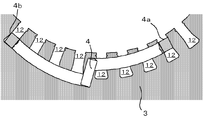
- FIG. 2 shows a cross section A-A ′ of the stator 2 shown in FIG. 1 of the AC motor 1.
- the stator core 3 has a plurality of slots 12 arranged at equal intervals on the inner peripheral side of the stator core 3.
- the stator coil 4 is inserted into the slot 12. When an alternating current flows through the stator coil 4, a rotating magnetic field is generated in the stator 2.
- the rotor 5 is disposed inside the stator 2 via a bearing and can rotate around the rotation axis AX.
- the rotor 5 includes a rotor shaft 8 that rotates about a rotation axis AX, a cylindrical rotor core 6 provided around the rotor shaft 8, and a rotor that is inserted into a slot of the rotor core 6. And a conductor 7.
- a rotating magnetic field is generated in the stator core 3.
- a current is induced in the rotor conductor 7 by this rotating magnetic field, and torque is generated in the rotor core 6 due to the interaction between the magnetic pole generated in the rotor core 6 and the magnetic pole of the rotating magnetic field by this induced current, and the rotor shaft 8 Rotates.
- the stator coil 4 is formed by winding a rectangular cross-section shaped conductor having an insulation coating as many times as necessary to form a coil shape, and the entire conductor arranged on the coil side maintains the rectangular shape.
- the outside is covered with an insulating tape or the like.
- the stator coil 4 is inserted across a plurality of slots 12 provided in the stator core 3.
- One coil side of the stator coil 4 is inserted into the back side of one of the plurality of slots 12 and is referred to as a lower opening coil 4b.
- the other coil side of the stator coil 4 is inserted into the entrance side of another slot 12 having a predetermined interval among the plurality of slots 12 and is referred to as an upper coil 4a. That is, in the AC motor 1, the stator coil 4 is inserted into the slot 12 by a two-layer winding method.
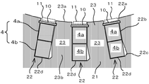
- the slot 12 has a width of 0.3 to 0.5 mm with respect to the maximum width of the coil sides (upper coil 4a, lower coil 4b) in which a plurality of insulating coated conductors are held in a rectangular shape with insulating tape or the like. It is set to be the added value. This facilitates the insertion of the stator coil 4 into the slot 12 and reduces the possibility of damage to the insulating layer on the surface of the stator coil 4 at the time of insertion.
- the coil sides (upper coil 4 a and lower coil 4 b) of the two stator coils 4 are arranged in the depth direction of the slot 12.
- a wedge 10 for preventing the stator coil 4 from dropping off is disposed at the entrance 12a of each slot 12, and a retreating portion 11 is provided for forming a passage through which cooling air flows when the AC motor 1 is operated. Yes.
- each slot 12 a space where the coil side on the lower coil 4 b side can be rotated on the back side of the slot 12 when the coil side on the upper coil 4 a side of the stator coil 4 is lifted from the slot 12. Is provided.
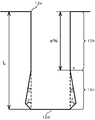
- FIG. 4 shows an enlarged view of the slot 12.
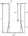
- the slot 12 includes a parallel groove portion 12 b having parallel inner walls facing each other with the same width as the entrance portion 12 a that is an opening thereof, a groove bottom portion 12 d that is a bottom surface of the slot 12, and An enlarged portion 12c in which the width of the slot 12 is increased is provided.
- a parallel groove portion 12b is formed at a depth of a% of the groove depth L from the entrance portion 12a to the groove bottom portion 12d.
- the depth position of a% is also referred to as a depth position e. a% is about 60%, and can be a numerical value of 50% or more and 70% or less, for example.
- the part from the depth position e of a% to the groove bottom part 12d is an enlarged part 12c.
- the groove width widens toward the groove bottom portion 12d at an opening angle of ⁇ degrees on both sides from the position of the depth of a%.
- the ⁇ degree is, for example, 10 degrees.
- the groove width is enlarged at an opening angle of ⁇ degrees on both sides from the groove bottom portion 12d toward the inlet portion 12a.
- the ⁇ degree is, for example, 45 degrees.
- a space is formed by widening the slot width by ⁇ degrees (first angle) from the predetermined depth position e of each slot 12 toward the groove bottom portion 12d.
- the predetermined depth position e is a depth position of about 60% of the entire depth L, and ⁇ degree is 10 degrees.
- each slot 12 a space is formed by widening the slot width by ⁇ degrees (second angle) from the groove bottom portion 12d toward the inlet side, and ⁇ degrees is 45 degrees.
- the cross-sectional shape of the entire slot 12 is an octagonal shape.
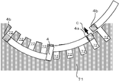
- stator coil 4 is inserted across the two slots 12. For example, a total of 36 stator coils 4 are inserted into the slot 12 for each AC motor 1 having 36 slots 12. For most of the stator coils 4, the respective coil sides (the upper coil 4a and the lower coil 4b) can be inserted into the two slots 12 spaced apart from each other without any problem. However, when one coil side of the last several stator coils 4 is inserted as the lower coil 4b in the back side of the slot 12, the coil side of another stator coil 4 that has already been inserted is the upper side. The coil 4a exists on the entrance side of the slot 12. For this reason, it is necessary to insert a coil side that becomes the lower opening coil 4b in a state where the upper opening coil 4a is lifted from the slot 12.
- the groove width is expanded at an opening angle of ⁇ degrees (10 degrees) on both sides from the position of a (about 60)% of the groove depth toward the groove bottom 12d.
- the lower coil 4b of the stator coil 4 inserted into the slot 12 can be inclined to an angle of ⁇ degrees (10 degrees) on the back side of the slot 12. Therefore, as shown in FIG. 5, the upper opening coil 4 a can be easily lifted to the outside of the slot 12. As a result, the upper coil 4a of another stator coil 4 that has already been inserted is lifted to the outside of the slot 12, and the lower coil 4b of the other stator coil 4 is moved in the direction of arrow B to the slot 12. The inserting operation can be easily performed.
- the lower coil 4b can be freely inclined up to the inclination of the tapered inner wall of the enlarged portion 12c of the slot 12, the lower coil 4b is not strongly pressed by the groove wall of the slot 12, and is fixed. Damage to the insulating layer on the surface of the child coil 4 can be prevented.
- a parallel groove portion 12b is formed from the entrance portion 12a to a position e having a depth of a% (about 60%) of the groove depth L. For this reason, in the state where all the stator coils 4 are inserted at predetermined positions, the groove width on the back side of the slot 12 is enlarged, but the upper portion of the lower coil 4b is held by the parallel groove portion 12b. .
- the predetermined depth position e is determined so that the upper portion of the lower opening coil 4b is within the range of the parallel groove portion 12b, and the lower opening coil 4b can be rotated in a space on the back side of the slot.
- the opening angle ⁇ degree (10 degrees), in which the groove width is expanded on both sides from the depth position e of a% (about 60%), is, as shown in FIG. 2, the stator core teeth 13 between the slots 12.
- the width of the tooth base portion 13b is determined to be larger than the width of the tooth tip portion 13a.
- the groove width can be expanded from the position e at a depth of a% (about 60%) of the slot 12 according to the number of the slots 12. If the opening angle ⁇ is set, the cross-sectional shape of the slot 12 can be set such that the tooth width of the tooth base portion 13b of the stator core tooth 13 between the slots 12 is larger than the tooth width of the tooth tip portion 13a. Become.
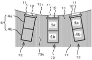
- the slot 72 provided between the stator core teeth 73 extending from the tooth tip portion 73a to the tooth root portion 73b is a generally parallel groove as shown in FIG. .
- the upper coil 4a and the lower coil 4b of the stator coil 4 are inserted inside the slot 72, which is a parallel groove, with a predetermined gap.
- the upper coil 4a of another stator coil 4 that has already been inserted exists in the slot 72.
- the slot 72 is a parallel groove
- the inserted upper coil 4a can be easily moved to the outside of the slot 72 as shown in FIG. Can't move on. Therefore, it is necessary to insert the lower coil 4b of the other stator coil 4 into the back side of the slot 72 while lifting the upper coil 4a of the inserted stator coil 4 in the direction of arrow C.
- the lifting of the upper coil 4a is accompanied by a slight deformation of the molded stator coil 4 because a space in which the lower coil 4b can rotate is not formed, so that a large force is required.
- the slot 12 is positioned at a depth of a% (about 60%) of the groove depth L from the inlet 12a of the slot 12 to the groove bottom 12d.
- the groove width is enlarged by an opening angle of ⁇ degrees (10 degrees) on both sides of the groove width direction from the depth position e of a% (about 60%) toward the groove bottom section 12d.
- the groove width is increased at an opening angle of ⁇ degrees (45 degrees) on both sides in the groove width direction from the bottom 12d toward the entrance 12a.
- the lower opening coil 4b can be tilted to an inclination in contact with the tapered inner wall of the slot 12, so that the corners of the wall surface of the slot 12 and the end of the stator core 3 can be inclined. The possibility of damaging the insulating layer on the surface of the stator coil 4 can be reduced.
- Embodiment 2 FIG. Next, a second embodiment of the present invention will be described.
- the configuration of the AC motor 1 according to the second embodiment is different from the configuration of the AC motor 1 according to the first embodiment only in the cross-sectional shape of the slot 22.
- the enlarged portion 22c in the second embodiment, as shown in FIGS. 8 and 9, in the enlarged portion 22c from the depth position e of about 60% to the groove bottom portion 22d, ⁇ degrees (10 degrees from the depth position e to one side in the groove width direction.
- the groove width is enlarged toward the groove bottom 22d at an opening angle of degrees.
- the enlarged portion 22c has a shape in which the groove width is enlarged to one side in the same direction at an opening angle of ⁇ degrees (45 degrees) from the groove bottom portion 22d toward the entrance side. In this way, the direction in which the stator coil 4 is inserted into the slot 22 is limited to one direction, but the same effect as in the first embodiment can be expected.
- the groove width of the slot 22 is increased only on one side. In this way, it is possible to increase the opening angle for expanding the slot width to 20 degrees while securing the tooth width of the root portion 23b of the stator core tooth 23 larger than that of the tooth tip portion 23a. is there. By doing so, it is also possible to expect an effect that the lifting operation of the upper coil portion 4a of the inserted coil can be further facilitated at the final stage of insertion of the stator coil 4.
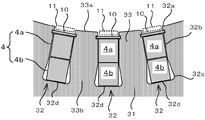
- Embodiment 3 FIG. Next, a third embodiment of the present invention will be described.
- the configuration of the AC motor 1 according to Embodiment 3 is different from the configuration of the AC motor 1 according to Embodiment 1 only in the shape of the slot 32.
- the slot width is enlarged toward the groove bottom 32d at an opening angle of ⁇ degrees (10 degrees).
- the surfaces extending from the groove bottom portion 32d to both sides in the groove width direction are concave curved surfaces.
- Embodiment 4 FIG. Next, a fourth embodiment of the present invention will be described.
- the configuration of the AC motor 1 according to Embodiment 4 is different from the configuration of the AC motor 1 according to Embodiment 3 only in the shape of the slot 42.
- the enlarged portion 42c from the depth position e of about 60% to the groove bottom portion 42d from the depth position e of about 60% to one side in the slot width direction.
- the groove width is expanded toward the groove bottom 42d at an opening angle of ⁇ degrees (10 degrees).
- the surface on the groove bottom side of the enlarged portion 42c is a concave curved surface on the same side as the direction in which the groove width is enlarged from the groove bottom portion 42d. In this way, the direction in which the stator coil 4 is inserted into the slot 42 is limited to one direction, but the same effect as in the third embodiment can be expected.
- the expansion of the slot width of the slot 42 is only on one side, and the groove width is increased while ensuring the tooth width of the tooth base portion 43b of the stator core teeth 43 larger than the tooth tip portion 43a as described above.
- the opening angle ⁇ can be increased up to 20 degrees, and the lifting operation of the inserted upper coil portion 4a in the final stage of the insertion of the stator coil 4 can be further facilitated.
- Embodiment 5 FIG. Next, a fifth embodiment of the present invention will be described.
- the configuration of the AC motor 1 according to Embodiment 5 is different from the configuration of the AC motor 1 according to Embodiment 1 only in the shape of the slot 52.
- the enlarged portions 52c from the depth position e of about 60% to the groove bottom 52d are respectively set to ⁇ degrees (10 degrees) on both sides from the depth position e.
- the groove width is increased toward the groove bottom 52d at an opening angle of.
- the entire shape of the slot 52 is a hexagonal shape. Even if the cross-sectional shape of the slot 52 is such a shape, the same effect as in the first embodiment can be expected.
- Embodiment 6 FIG. Next, a sixth embodiment of the present invention will be described.
- the configuration of the AC motor 1 according to Embodiment 6 is different from the configuration of the AC motor 1 according to Embodiment 5 only in the shape of the slot 62.
- the enlarged portion 62c from the depth position e of about 60% to the groove bottom 62d is set to ⁇ degree (10 degrees) from the depth position e to one side.
- the groove width is increased toward the groove bottom 62d at an opening angle.
- the overall shape of the groove is a pentagonal shape. In this way, the direction in which the stator coil 4 is inserted into the slot 62 is limited to one direction, but the same effect as in the fifth embodiment can be expected.
- the groove width of the slot 62 is enlarged only on one side, and the width of the slot 62 is increased while the tooth width of the tooth base portion 63b of the stator core teeth 63 is made larger than the tooth tip portion 63a as described above.
- the opening angle to be expanded can be increased up to about 20 degrees, and the lifting operation of the inserted upper opening coil 4a in the final stage of the insertion of the stator coil 4 can be further facilitated.
- the cross-sectional shape of the slot is not limited to that of the above embodiments.
- the depth a% of the expansion start position e on the inlet side of the enlarged portion can be arbitrarily determined, and the opening angles ⁇ and ⁇ of the enlarged portion can also be arbitrarily set, and the groove bottom of the groove width enlarged portion
- the side shape can also be set arbitrarily.
- the first angle is determined so that the width of the root portion of the stator core teeth is not narrower than the width of the tooth tip portion, and the power factor in the AC motor 1 is not provided on the back side of the slot. It is possible to maintain almost the same as the case.
- each slot 22, 42, 62 the space is provided on one side in the slot width direction, and the insertion direction of the stator coil 4 is limited to one direction, but the first angle of the space on the back side of the slot is Can be bigger.
- the angle can be increased up to 20 degrees.
- the width of the root part of the stator core teeth may be set wider than the width of the tooth tip part and is not limited to 20 degrees.
- This invention is suitable for use as the structure of the stator of a two-layer winding type AC motor.
- the AC motor may be an induction motor or a synchronous motor.
- stator core 1 AC motor, 2 stator, 3 stator core, 4 stator coil, 4a upper coil, 4b lower coil, 5 rotor, 6 rotor core, 7 rotor conductor, 8 rotor shaft, 9 frame, 10 wedges, 11 retracted parts, 12 slots, 12a entrance parts, 12b parallel groove parts, 12c enlarged parts, 12d groove bottom parts, 13 stator core teeth, 13a tooth tip parts, 13b tooth root parts, 21 stator cores, 22 slots, 22a entrance part, 22b parallel groove part, 22c enlarged part, 22d groove bottom part, 23 stator core tooth, 23a tooth tip part, 23b root part, 31 stator core, 32 slot, 32a entrance part, 32b parallel groove part, 32c enlarged Part, 32d groove bottom part, 33 stator core teeth, 33a tooth tip part, 33b tooth root part, 41 stator core, 42 Slot, 42a entrance part, 42b parallel groove part, 42c enlarged part, 42d groove bottom part, 43 stator core tooth, 43a tooth tip part, 43
Landscapes
- Engineering & Computer Science (AREA)
- Power Engineering (AREA)
- Manufacturing & Machinery (AREA)
- Manufacture Of Motors, Generators (AREA)
- Iron Core Of Rotating Electric Machines (AREA)
- Insulation, Fastening Of Motor, Generator Windings (AREA)
Abstract
Description
以下、この発明の実施の形態1について説明する。
次に、この発明の実施の形態2について説明する。
次に、この発明の実施の形態3について説明する。
次に、この発明の実施の形態4について説明する。
次に、この発明の実施の形態5について説明する。
次に、この発明の実施の形態6について説明する。
Claims (11)
- 複数のスロットが設けられた固定子鉄心と、
長方形断面形状に成形され、一方のコイル辺が前記複数のスロットのうちの一のスロットの奥側に挿入され、他方のコイル辺が前記複数のスロットのうちの他のスロットの入り口側に挿入されることにより、二層巻方式で前記各スロットに挿入される複数の固定子コイルと、
を備え、
前記各スロットには、
前記他方のコイル辺が前記他のスロットから持ち上げられた場合に、前記一方のコイル辺をスロットの奥側で回動させることができるスペースが設けられている、
交流電動機。 - 前記各スロットでは、
所定の深さ位置までスロット幅が均一であり、
前記所定の深さ位置から溝底側に向かって前記スロット幅を広げることにより、
前記スペースが形成されている、
請求項1に記載の交流電動機。 - 前記各スロットでは、
前記所定の深さ位置から溝底部に向かって、第1の角度で、前記スロット幅が広げられている、
請求項2に記載の交流電動機。 - 前記所定の深さ位置は、
前記一方のコイル辺の上部が前記スロット幅が均一な部分にあり、前記スペースにより前記一方のコイル辺が回動可能となるように決められている、
請求項2又は3に記載の交流電動機。 - 前記スペースは、前記所定の深さ位置から前記溝底部までのスロット幅が、
前記一方のコイル辺を前記各スロットの奥側で回動させた場合に、前記他方のコイル辺が前記他のスロットから外部に退出可能となるように決められている、
請求項2から4のいずれか一項に記載の交流電動機。 - 前記スペースは、
前記各スロット間の固定子鉄心歯の歯元部の幅を歯先部の幅よりも大きく確保するように決められている、
請求項5に記載の交流電動機。 - 前記各スロットでは、
溝底部から入口側に向かって前記スロット幅を広げることにより、
前記スペースが形成されている、
請求項2から6のいずれか一項に記載の交流電動機。 - 前記各スロットでは、
前記溝底部から入口側に向かって、第2の角度で、前記スロット幅が広げられている、
請求項7に記載の交流電動機。 - 前記各スロットでは、
前記溝底部から入口側に向かって、凹曲面が形成されている、
請求項7に記載の交流電動機。 - 前記各スロットでは、
前記スペースが前記スロットの幅方向の両側に設けられている、
請求項1から9のいずれか一項に記載の交流電動機。 - 前記各スロットでは、
前記スペースが前記スロットの幅方向の片側に設けられている、
請求項1から9のいずれか一項に記載の交流電動機。
Priority Applications (5)
| Application Number | Priority Date | Filing Date | Title |
|---|---|---|---|
| EP14899239.9A EP3179603B1 (en) | 2014-08-08 | 2014-08-08 | Alternating-current motor |
| CN201480081092.9A CN106663971B (zh) | 2014-08-08 | 2014-08-08 | 交流电动机 |
| PCT/JP2014/071097 WO2016021070A1 (ja) | 2014-08-08 | 2014-08-08 | 交流電動機 |
| JP2016539796A JP6203408B2 (ja) | 2014-08-08 | 2014-08-08 | 交流電動機 |
| US15/502,337 US20170237324A1 (en) | 2014-08-08 | 2014-08-08 | Alternating-current motor |
Applications Claiming Priority (1)
| Application Number | Priority Date | Filing Date | Title |
|---|---|---|---|
| PCT/JP2014/071097 WO2016021070A1 (ja) | 2014-08-08 | 2014-08-08 | 交流電動機 |
Publications (1)
| Publication Number | Publication Date |
|---|---|
| WO2016021070A1 true WO2016021070A1 (ja) | 2016-02-11 |
Family
ID=55263371
Family Applications (1)
| Application Number | Title | Priority Date | Filing Date |
|---|---|---|---|
| PCT/JP2014/071097 Ceased WO2016021070A1 (ja) | 2014-08-08 | 2014-08-08 | 交流電動機 |
Country Status (5)
| Country | Link |
|---|---|
| US (1) | US20170237324A1 (ja) |
| EP (1) | EP3179603B1 (ja) |
| JP (1) | JP6203408B2 (ja) |
| CN (1) | CN106663971B (ja) |
| WO (1) | WO2016021070A1 (ja) |
Cited By (2)
| Publication number | Priority date | Publication date | Assignee | Title |
|---|---|---|---|---|
| WO2019189478A1 (ja) * | 2018-03-30 | 2019-10-03 | 日本電産株式会社 | ステータおよびモータ |
| JP2022110252A (ja) * | 2021-01-18 | 2022-07-29 | トヨタ紡織株式会社 | 電機子の製造方法、電機子、及び鉄心 |
Families Citing this family (8)
| Publication number | Priority date | Publication date | Assignee | Title |
|---|---|---|---|---|
| DE102015201731A1 (de) * | 2014-11-13 | 2016-05-19 | Robert Bosch Gmbh | Elektrische Maschine |
| JP6779527B2 (ja) * | 2017-08-04 | 2020-11-04 | 株式会社小田原エンジニアリング | コイル組立装置、コイル組立方法及び回転電機の製造装置 |
| CN120127852A (zh) * | 2018-12-28 | 2025-06-10 | 福特全球技术公司 | 用于电机的定子及电机 |
| JP2022055714A (ja) * | 2020-09-29 | 2022-04-08 | 本田技研工業株式会社 | 回転電機 |
| JP2022055707A (ja) * | 2020-09-29 | 2022-04-08 | 本田技研工業株式会社 | 回転電機 |
| JP2022055717A (ja) * | 2020-09-29 | 2022-04-08 | 本田技研工業株式会社 | 回転電機 |
| FR3126564B1 (fr) * | 2021-08-24 | 2024-02-16 | Valeo Equip Electr Moteur | Procédé et ensemble d’assemblage d’épingles conductrices pour une machine électrique tournante |
| JP2023146831A (ja) * | 2022-03-29 | 2023-10-12 | ニデック株式会社 | ステータ及びウェッジ挿入装置 |
Citations (4)
| Publication number | Priority date | Publication date | Assignee | Title |
|---|---|---|---|---|
| JPS5321703A (en) * | 1976-08-13 | 1978-02-28 | Hitachi Ltd | Armature |
| JPS5788843A (en) * | 1980-11-25 | 1982-06-02 | Hitachi Ltd | Stator core for rotary electric machine |
| JP2007512797A (ja) * | 2003-11-24 | 2007-05-17 | ティーエム4・インコーポレーテッド | 発電電動機械ステータ及び予め巻かれたコイルをそれに取り付けるための方法 |
| JP2014135786A (ja) * | 2013-01-08 | 2014-07-24 | Toyota Motor Corp | 回転電機用ステータおよび回転電機 |
Family Cites Families (7)
| Publication number | Priority date | Publication date | Assignee | Title |
|---|---|---|---|---|
| US740403A (en) * | 1902-11-17 | 1903-10-06 | Howard Dorrance Day | Ball. |
| JPH08298756A (ja) * | 1995-04-25 | 1996-11-12 | Toyota Motor Corp | モータのステータ作製方法およびステータコア |
| JP3308828B2 (ja) * | 1996-10-18 | 2002-07-29 | 株式会社日立製作所 | 永久磁石回転電機及びそれを用いた電動車両 |
| JPH1198791A (ja) * | 1997-09-16 | 1999-04-09 | Mitsubishi Heavy Ind Ltd | ブラシレスdcモータ |
| JP2011087373A (ja) * | 2009-10-14 | 2011-04-28 | Railway Technical Res Inst | 誘導電動機 |
| JP2014054044A (ja) * | 2012-09-06 | 2014-03-20 | Toyota Motor Corp | ステータ及びこのステータを備えた回転電機 |
| JP5999647B2 (ja) * | 2013-01-08 | 2016-09-28 | 株式会社ビスキャス | 金属被覆ケーブルの金属被覆拡径冶具、および金属被覆ケーブルと接続銅管との接合方法及び接合構造 |
-
2014
- 2014-08-08 EP EP14899239.9A patent/EP3179603B1/en active Active
- 2014-08-08 CN CN201480081092.9A patent/CN106663971B/zh active Active
- 2014-08-08 US US15/502,337 patent/US20170237324A1/en not_active Abandoned
- 2014-08-08 JP JP2016539796A patent/JP6203408B2/ja active Active
- 2014-08-08 WO PCT/JP2014/071097 patent/WO2016021070A1/ja not_active Ceased
Patent Citations (4)
| Publication number | Priority date | Publication date | Assignee | Title |
|---|---|---|---|---|
| JPS5321703A (en) * | 1976-08-13 | 1978-02-28 | Hitachi Ltd | Armature |
| JPS5788843A (en) * | 1980-11-25 | 1982-06-02 | Hitachi Ltd | Stator core for rotary electric machine |
| JP2007512797A (ja) * | 2003-11-24 | 2007-05-17 | ティーエム4・インコーポレーテッド | 発電電動機械ステータ及び予め巻かれたコイルをそれに取り付けるための方法 |
| JP2014135786A (ja) * | 2013-01-08 | 2014-07-24 | Toyota Motor Corp | 回転電機用ステータおよび回転電機 |
Cited By (3)
| Publication number | Priority date | Publication date | Assignee | Title |
|---|---|---|---|---|
| WO2019189478A1 (ja) * | 2018-03-30 | 2019-10-03 | 日本電産株式会社 | ステータおよびモータ |
| JP2022110252A (ja) * | 2021-01-18 | 2022-07-29 | トヨタ紡織株式会社 | 電機子の製造方法、電機子、及び鉄心 |
| JP7468372B2 (ja) | 2021-01-18 | 2024-04-16 | トヨタ紡織株式会社 | 電機子の製造方法及び電機子 |
Also Published As
| Publication number | Publication date |
|---|---|
| CN106663971A (zh) | 2017-05-10 |
| JP6203408B2 (ja) | 2017-09-27 |
| CN106663971B (zh) | 2019-07-05 |
| EP3179603A4 (en) | 2018-04-04 |
| JPWO2016021070A1 (ja) | 2017-04-27 |
| EP3179603A1 (en) | 2017-06-14 |
| US20170237324A1 (en) | 2017-08-17 |
| EP3179603B1 (en) | 2020-09-23 |
Similar Documents
| Publication | Publication Date | Title |
|---|---|---|
| JP6203408B2 (ja) | 交流電動機 | |
| US8482179B2 (en) | Brushless motor having a reduced axial dimension | |
| US8461737B2 (en) | Permanent-magnet (PM) rotors and systems | |
| JP2007512797A (ja) | 発電電動機械ステータ及び予め巻かれたコイルをそれに取り付けるための方法 | |
| TWI555307B (zh) | Permanent magnet motor | |
| CN104184226B (zh) | 电动机以及具备该电动机的压缩机 | |
| JP5610989B2 (ja) | 回転電動機 | |
| CN107873118A (zh) | 高转子磁极开关磁阻电机的镜像 | |
| CN105406629A (zh) | 电机定子、永磁发电机 | |
| JP2002335643A (ja) | 電動機 | |
| CN110663158A (zh) | 用于交流电机的双磁相材料环 | |
| WO2018066654A1 (ja) | 同期リラクタンス型回転電機 | |
| CN109716617B (zh) | 转子、用于制造转子的方法、磁阻电机和做功机械 | |
| KR20190048745A (ko) | 헤어핀 권선 모터의 고정자구조 | |
| JP5248751B2 (ja) | スロットレス永久磁石型回転電機 | |
| JP2011147346A (ja) | 電動機 | |
| CN207368762U (zh) | 电机 | |
| CA2963950C (en) | Active part of an electric machine | |
| JP6676195B2 (ja) | 回転電機、及びその回転電機を備えるエレベータ用巻上機 | |
| US20200161949A1 (en) | Double-stator single-winding switched reluctance machine | |
| TWI678053B (zh) | 無槽式電動機、以及使用其之電動送風機或電動吸塵器 | |
| JP2011259630A (ja) | 電気機械装置 | |
| US20180097418A1 (en) | Coils for electrical machines | |
| JP4870340B2 (ja) | 電動機 | |
| JPH04271258A (ja) | モータ |
Legal Events
| Date | Code | Title | Description |
|---|---|---|---|
| 121 | Ep: the epo has been informed by wipo that ep was designated in this application |
Ref document number: 14899239 Country of ref document: EP Kind code of ref document: A1 |
|
| ENP | Entry into the national phase |
Ref document number: 2016539796 Country of ref document: JP Kind code of ref document: A |
|
| REEP | Request for entry into the european phase |
Ref document number: 2014899239 Country of ref document: EP |
|
| WWE | Wipo information: entry into national phase |
Ref document number: 2014899239 Country of ref document: EP |
|
| NENP | Non-entry into the national phase |
Ref country code: DE |