WO2016021364A1 - 物品の搬送方法及びその装置 - Google Patents
物品の搬送方法及びその装置 Download PDFInfo
- Publication number
- WO2016021364A1 WO2016021364A1 PCT/JP2015/069774 JP2015069774W WO2016021364A1 WO 2016021364 A1 WO2016021364 A1 WO 2016021364A1 JP 2015069774 W JP2015069774 W JP 2015069774W WO 2016021364 A1 WO2016021364 A1 WO 2016021364A1
- Authority
- WO
- WIPO (PCT)
- Prior art keywords
- conveyance
- curvature
- article
- transport
- rotary
- Prior art date
- Legal status (The legal status is an assumption and is not a legal conclusion. Google has not performed a legal analysis and makes no representation as to the accuracy of the status listed.)
- Ceased
Links
Images


Classifications
-
- B—PERFORMING OPERATIONS; TRANSPORTING
- B65—CONVEYING; PACKING; STORING; HANDLING THIN OR FILAMENTARY MATERIAL
- B65G—TRANSPORT OR STORAGE DEVICES, e.g. CONVEYORS FOR LOADING OR TIPPING, SHOP CONVEYOR SYSTEMS OR PNEUMATIC TUBE CONVEYORS
- B65G47/00—Article or material-handling devices associated with conveyors; Methods employing such devices
- B65G47/74—Feeding, transfer, or discharging devices of particular kinds or types
- B65G47/84—Star-shaped wheels or devices having endless travelling belts or chains, the wheels or devices being equipped with article-engaging elements
- B65G47/846—Star-shaped wheels or wheels equipped with article-engaging elements
-
- B—PERFORMING OPERATIONS; TRANSPORTING
- B65—CONVEYING; PACKING; STORING; HANDLING THIN OR FILAMENTARY MATERIAL
- B65G—TRANSPORT OR STORAGE DEVICES, e.g. CONVEYORS FOR LOADING OR TIPPING, SHOP CONVEYOR SYSTEMS OR PNEUMATIC TUBE CONVEYORS
- B65G29/00—Rotary conveyors, e.g. rotating discs, arms, star-wheels or cones
-
- B—PERFORMING OPERATIONS; TRANSPORTING
- B67—OPENING, CLOSING OR CLEANING BOTTLES, JARS OR SIMILAR CONTAINERS; LIQUID HANDLING
- B67B—APPLYING CLOSURE MEMBERS TO BOTTLES JARS, OR SIMILAR CONTAINERS; OPENING CLOSED CONTAINERS
- B67B3/00—Closing bottles, jars or similar containers by applying caps
- B67B3/02—Closing bottles, jars or similar containers by applying caps by applying flanged caps, e.g. crown caps, and securing by deformation of flanges
-
- B—PERFORMING OPERATIONS; TRANSPORTING
- B67—OPENING, CLOSING OR CLEANING BOTTLES, JARS OR SIMILAR CONTAINERS; LIQUID HANDLING
- B67C—CLEANING, FILLING WITH LIQUIDS OR SEMILIQUIDS, OR EMPTYING, OF BOTTLES, JARS, CANS, CASKS, BARRELS, OR SIMILAR CONTAINERS, NOT OTHERWISE PROVIDED FOR; FUNNELS
- B67C3/00—Bottling liquids or semiliquids; Filling jars or cans with liquids or semiliquids using bottling or like apparatus; Filling casks or barrels with liquids or semiliquids
- B67C3/02—Bottling liquids or semiliquids; Filling jars or cans with liquids or semiliquids using bottling or like apparatus
- B67C3/22—Details
- B67C3/24—Devices for supporting or handling bottles
-
- B—PERFORMING OPERATIONS; TRANSPORTING
- B67—OPENING, CLOSING OR CLEANING BOTTLES, JARS OR SIMILAR CONTAINERS; LIQUID HANDLING
- B67C—CLEANING, FILLING WITH LIQUIDS OR SEMILIQUIDS, OR EMPTYING, OF BOTTLES, JARS, CANS, CASKS, BARRELS, OR SIMILAR CONTAINERS, NOT OTHERWISE PROVIDED FOR; FUNNELS
- B67C7/00—Concurrent cleaning, filling, and closing of bottles; Processes or devices for at least two of these operations
- B67C7/0006—Conveying; Synchronising
- B67C7/004—Conveying; Synchronising the containers travelling along a circular path
-
- B—PERFORMING OPERATIONS; TRANSPORTING
- B65—CONVEYING; PACKING; STORING; HANDLING THIN OR FILAMENTARY MATERIAL
- B65G—TRANSPORT OR STORAGE DEVICES, e.g. CONVEYORS FOR LOADING OR TIPPING, SHOP CONVEYOR SYSTEMS OR PNEUMATIC TUBE CONVEYORS
- B65G2201/00—Indexing codes relating to handling devices, e.g. conveyors, characterised by the type of product or load being conveyed or handled
- B65G2201/02—Articles
- B65G2201/0235—Containers
Definitions
- the present invention relates to an article conveying method and apparatus, and more particularly, to an article conveying method and apparatus for delivering and transferring an article from a circular conveyance to a circular conveyance between rotating conveyance bodies.
- Articles such as cylindrical containers (hereinafter simply referred to as containers) between turrets, rotors, star wheels, etc. (hereinafter collectively referred to as turrets or rotary carriers) having pockets formed at equal pitches on the outer periphery.
- the turret is usually installed so that the pitch circles of the pockets are in contact with each other, and rotate at the same peripheral speed to deliver an object from the upstream turret to the downstream turret.
- the change in acceleration applied to the container to be transported becomes infinite, causing problems such as wrinkles and depressions in the container, and wear of the guides.
- the problem has become prominent with the increase in the speed of fillers and seams using cans and the thinning of cans.
- a dispensing device having a pressing plate that is forcibly controlled so as to move the bottle radially outward at one delivery position, and rapidly reducing the conveyance speed of the bottle to the speed of the other rotor (Patent Document 1) Or a star wheel for supplying a container to the filler main body, and the pitch circle between them is separated by a predetermined offset amount, and the container trajectory from the star wheel to the filler main body is follow a connection curve consisting of a spiral curve that continuously changes from the same curvature as the pitch circle of the star wheel to the same curvature as the pitch circle of the filler body. Installation containers feeder guides to have been proposed (see Patent Document 2).
- the former apparatus gradually moves the turret between the turrets in the radial direction by holding the bottle held in the pocket by the presser plate.
- the device is complicated, such as requiring a special presser plate and accessories in the pocket, making it difficult to apply to high-speed production lines.
- the latter device can prevent a sudden change in acceleration, but must support the can in the pocket of the delivery side turret (star wheel).
- the present invention provides a method and apparatus for conveying articles in which the acceleration during the delivery of articles between turrets smoothly changes and the distance between turret shafts is not required in the delivery of articles between turrets.
- the purpose is to provide.
- the article transport method of the present invention that solves the above-described problem is a method for transporting an article from a circular transport to a circular transport between rotary transport bodies, wherein the pitch circles of the rotary transport bodies have a predetermined gap.
- the rotational transport body is installed to have both the pitch circles along the transition curve in which the curvature continuously changes from the pitch curvature of the rotary transport body before delivery to the pitch curvature of the rotary transport body after delivery.
- the article is conveyed.
- the circular pitch between adjacent pockets of the rotary transport body is different from each other, and the transport speed between the rotary transport bodies continuously changes from the peripheral speed of the circular transport before delivery to the peripheral speed of the circular transport after delivery. It is desirable.
- the ratio of the angular velocities of the rotary transport bodies is equal to the ratio of the reciprocal number of pockets of the respective rotary transport bodies. Further, it is desirable that the conveyance between the rotary conveyance bodies is carried along a conveyance guide having a guide surface having an offset transition curve obtained by offsetting the transition curve.
- any one of the curves c 1 to c 4 obtained by any of the following formulas 1 to 4 is used as the transition curve.
- s curve length
- ⁇ is determined from the transition curve length and the pitch circle radius of the rotating carrier
- the curvature ⁇ of the transition curve is S: curve length (parameter)
- s R transition curve length
- R pitch circle radius of rotating carrier
- n parameter representing the degree of curvature change It is.
- ⁇ is a parameter representing the degree of curvature change, and t and ⁇ are determined from the length of the transition curve and the pitch circle radius of the rotating carrier.
- curvature ⁇ of the transition curve is S: curve length (parameter), s R : transition curve length, R: pitch circle radius of rotating carrier, n: parameter representing the degree of curvature change It is. )
- An article transport apparatus for delivering an article from a circular transport to a circular transport between rotating transport bodies, wherein the outer peripheral portion has pockets formed at equal pitches.
- the rotary transport body and a receiving-side rotary transport body having pockets formed at equal pitches on the outer peripheral portion, and the transfer-side rotary transport body and the receiving-side rotary transport body have a predetermined gap between the pitch circles of circular transport.
- a conveyance guide that conveys articles along a predetermined path is provided between them, and the shape of the guide surface of the conveyance guide is determined based on the pitch curvature of the circle conveyance before delivery. It is an offset transition curve obtained by offsetting a transition curve that continuously changes in pitch curvature.
- the delivery-side rotary transport body and the receiving-side rotary transport body are configured so that one of the rotary transport bodies does not change the axial center position of the virtual rotary transport body that delivers the article with the pitch circles of both rotary transport bodies in contact with each other.
- the pitch circle radius of the body is reduced, and the conveyance speed between the rotary conveyance bodies continuously changes from the circumferential speed of the circular conveyance before delivery to the circumferential speed of the circular conveyance after delivery, and the delivery-side rotary conveyance body and the reception It is desirable that the ratio of the angular velocities of the side rotary transport bodies is equal to the ratio of the reciprocal of the number of pockets formed in each of the rotary transport bodies.
- the transition curve is any one of the curves c 1 to c 4 obtained by any one of the formulas 1 to 4.
- the pocket shape of the rotating conveyance body is an article guide portion whose arc-shaped opening end extends outward from the pitch circle, and the shape of the article guide portion and the pocket shape are determined from the circumferential speed of the circular conveyance before delivery. It is desirable for the shape to be in contact with the article to be conveyed with the conveying speed continuously changing to the peripheral speed of circular conveyance after delivery.
- the transport is performed. Since the acceleration applied to the article such as the container to be carried can be smoothly changed and transferred to the downstream rotary carrier, the damage to the article to be conveyed is small and the occurrence of dents and wrinkles in the article is reduced. be able to.
- the conveyance speed between the rotary conveyance bodies is continuously from the circumferential speed of the circular conveyance before delivery to the circumferential speed of the circular conveyance after delivery.
- the conveyance between the rotary conveyance bodies is a conveyance guide having a guide surface of an offset transition curve obtained by offsetting a transition curve in which the curvature continuously changes. Since it carries out along, it can convey stably.
- the acceleration applied to the article is continuously increased by using the curve defined by the above-described formula as the shape of the conveyance guide surface. And can be changed smoothly.
- the article conveying apparatus of the present invention described in claim 7 it can be applied without changing the inter-axis distance of the rotary conveying body of the existing apparatus and equipment, and the existing equipment can be made easily and inexpensively. Can be updated. Furthermore, according to the article transport apparatus of the present invention according to claim 9, stable delivery of the article by regulating the pockets so that the pocket projects outward from the pitch circle and the article transport speed continuously changes. Can do.
- FIG. 1 shows a seam turret (half mold turret) 1 of a can seamer that seals a can by sealing the can lid after filling the contents into a cylindrical can body, and the can body after filling and sealing is discharged.
- the embodiment applied to the delivery part of the discharge turret 2 is shown.
- the basic structure of this can seamer is the same as that of the prior art, and the can body flow in the can seamer is as shown in FIG.
- the can lid 20 is covered with the can body by the cover feed turret 11 and transferred to the seaming turret 1, and is held in the pocket 3 of the seaming turret 1 and is tightened while being conveyed along the circular orbit. Is called.
- the can body 25 with the can lid wound up is transferred from the seaming turret 1 to the discharge turret 2, held in the pocket 4, moved along a circular path, transferred to the discharge conveyor 5, and then transferred to the discharge conveyor 5. Transport to process.
- the conveyance guide (1) is conveyed along a curve in which the curvature continuously changes, and the object to be conveyed (can body) ) to join (centrifugal) by changing the acceleration in a continuous, (2) v decelerated in succession from 1 to v 2, is varied by continuously (conveying direction) acceleration.
- the distance between the axial centers O 1 and O 2 of the seaming turret 1 and the discharge turret 2 which are rotating conveyance bodies is the same as the axial distance between the turrets installed so as to be in contact with a conventional pitch circle.
- the pitch circle of the discharge turret 2 is set to R 2 smaller than the conventional pitch circle radius R 20 . That is, the seaming turret 1 and the discharge turret 2 are the same as the seaming turret 1 and the discharge turret in the combination of the virtual seaming turret and the discharge turret in which the pitch circles of the two rotary conveyance bodies contact each other and transfer the can from the circular conveyance to the circular conveyance.
- the pitch circle radius of the discharge turret 2 that is one of the rotary conveyance bodies is small, and the circular pitch (arc pitch) between the adjacent pockets of the seaming turret 1 and the discharge turret 2 is small. They are different from each other.
- PC 20 is a pitch circle of a conventional discharge turret having a pitch circle radius R 20
- PC 2 is a pitch circle of the discharge turret 2 of the present embodiment having a pitch circle radius R 2 .
- the curvature of the trajectory curve followed by the can transported between the circular transport turrets is changed from the circular transport pitch circular curvature 1 / R 1 before delivery to the circular curvature pitch circle curvature 1 / R after delivery. It changes continuously to 2 .
- the conveying speed of the can body 25 which is conveyed between the adjacent circular conveyance varies continuously from the peripheral speed v 1 of the delivery previous circle conveyed to the peripheral speed v 2 of the circular transport after delivery.
- the guide surface has a similar curvature so as to change continuously from the circular conveyance pitch curvature 1 / R 1 before delivery to the pitch curvature 1 / R 2 of circle delivery after delivery.
- An outer guide 6 and an inner guide 7 having an offset transition curve shape that changes in the above are installed along the delivery portion.
- a curve known as a clothoid curve in which the curvature changes in proportion to the length of the curve and three types of curves as shown in Patent Document 3 can be applied. It can.
- the curve described in Patent Document 3 was devised and proposed by the present inventor as a connection curve when a container is transferred from a circular orbit to a linear orbit in the filler, but a transition curve from a circular orbit to a circular orbit.
- the present invention is also applied to the present invention by paying attention to the fact that it can also be applied.
- any one of the four types of curves c 1 , c 2 , c 3 , and c 4 shown in FIG. 3 and the following is adopted, and each of them has a curvature 1 / R of the turret 1.
- 1 is a curve that continuously changes from the curvature of the turret 2 to ⁇ 1 / R 2 , and the curvature continuously changes from positive to negative without bending in the middle.
- the following curves c 1 , c 2 , c 3 , and c 4 represent portions from the turret curvature 1 / R 1 to the curvature zero.
- the transfer curve c 1 is obtained by Equation 1. In the equation, s is a curve length, and the parameter ⁇ is determined from the length s R of the transition curve and the pitch circle radius R of the rotating carrier as in the following equation.
- the transition curve c 2 is obtained by Expression 2.
- the curvature ⁇ of the transition curve is In the formula, s is a curve length, s R is a transition curve length, R is a pitch circle radius of the rotating carrier, and n is a parameter representing a degree of curvature change.
- the transition curve c 3 is expressed by Equation 3.
- ⁇ is a parameter representing the degree of curvature change
- the curve length s is obtained by Equation 3-1.
- the curvature ⁇ of the curve can be obtained by Equation 3-2. From Equations 3-1 and 3-2, the parameters t and ⁇ can be determined from the transition curve length and the pitch circle radius of the rotating carrier with respect to an arbitrary value of the parameter ⁇ representing the degree of curvature change. Therefore, the transition curve c 3 can be obtained using Equation 3.
- Transition curve c 4 is represented by Equation 4. However, the curvature ⁇ of the transition curve is Where s is the curve length (parameter), s R is the transition curve length, R is the pitch circle radius of the rotating carrier, and n is a parameter indicating the degree of curvature change. It is.
- FIG. 3A shows a change in curvature with respect to the length along the line
- FIG. 3B shows a speed diagram in which the speed at that time continuously changes.
- the seaming turret 1 and the discharge turret 2 are installed when the pitch circle radius of the seaming turret 1 is R 1 and the pitch circle radius of the discharge turret 2 is R 20 as in the prior art.
- the outer guide 6 and the inner guide 7 having a curved guide surface are installed such that the distance K is K ⁇ D with respect to the diameter D (pocket fitting position) of the can body.
- the outer guide 6 and the inner guide 7 are installed along both sides of the transition track, but the guides on both sides are not necessarily required, and only one side or, for example, half of the transition track is the inner guide, It is also possible to install the other half as an outer guide only.
- the curvature at the delivery start position from the turret 1 starts from the curvature 1 / R 1 of the turret 1 and the curvature of the discharge turret 2 at the delivery end position to the discharge turret 2 ( ⁇ 1 / R 2 ), and the curvature changes continuously between them.
- the centrifugal acceleration applied to the can changes continuously and smoothly, and the impact is alleviated.
- it is decelerated by continuously changing the conveying direction acceleration in a continuous and from the peripheral speed v 1 of the seaming turret 1 to the peripheral speed v 2 of the discharge turret 2.
- the vertical axis represents the curvature
- the horizontal axis represents the length of the transition trajectory (curve).
- FIG. 3 (b) shows a change in the transport speed in FIG. 3 (b), smoothly is continuously decelerated from the conveying speed v 1 in the seaming turret 1 to the conveying speed v 2 in the discharge turret 2 at the transition orbit discharge It can be seen that the turret 2 is delivered.
- different transition curves may be used between the time when the curvature of the turret 1 becomes 1 / R 1 and the time when the curvature becomes zero and the time when the curvature of the turret 1 coincides with the curvature of the discharge turret 2 ( ⁇ 1 / R 2 ).
- the curvature of the discharge turret 2 from zero curvature (- A transition curve c 2 in which the curvature changes in a curve with respect to the length of the curve may be used until it is equal to 1 / R 2 ).
- Pocket 4 of the discharge turret 2 conventional pitch circle pitch radius R 2 radius R 20 is smaller than min, as shown in FIG. 1, the outer and the arcuate opening end portions 15, 16 than a pitch circle radius R 2 And projecting in the direction.
- a line diagram 17 in FIG. 1B shows the trajectory of the container moving away from the pocket 3 of the seaming turret 1, and the tangential direction to the pitch circle with respect to the axis O 1 passing through the center of the pocket 3 is x H. , has a normal direction and y H.
- FIG. 1C shows the trajectory of the container entering the pocket 4 of the discharge turret 2, and the direction tangent to the pitch circle with respect to the axis O 2 passing through the center of the pocket 4 is x D , the normal direction is set to y D.
- the pocket shape of each turret and the shape of the arcuate opening end can be determined.
- the arcuate opening end of the pocket 4 of the discharge turret 2 is formed to protrude outward from the pitch circle radius R 2 in order to more reliably deliver the article.
- the present invention is not limited to this. Instead, the arc-shaped opening end of the pocket 3 of the seaming turret 1 may protrude outward from the pitch circle radius, or the arc-shaped opening ends of both turret pockets may protrude.
- the present invention it is possible to continuously and smoothly change the acceleration applied to the can body in the process of being transferred from the circular orbit to the circular orbit.
- the conventional transfer device between turrets it is constructed by reducing the pitch circle radius of one of the turrets without changing the distance between the turret axes, and the existing devices and equipment can be easily modified. Can be achieved.
- the can seamer is applied between the seaming turret and the discharge turret has been described.
- the present invention is not limited to the above-described embodiment, and the delivery of articles from the circular orbit to the circular orbit.
- the present invention can also be applied to delivery and conveyance of articles between various equipment such as neckers and trimmers in a can production line and various turrets in a production line such as plastic bottles and paper containers.
- the present invention has high industrial applicability as an article conveying method and apparatus for delivering an article from a circular orbit to a circular orbit without damaging the conveyed article.
Landscapes
- Engineering & Computer Science (AREA)
- Mechanical Engineering (AREA)
- Specific Conveyance Elements (AREA)
- Filling Of Jars Or Cans And Processes For Cleaning And Sealing Jars (AREA)
Abstract
回転搬送体間の物品の受渡し搬送において、回転搬送体(1、2)のピッチ円同士が所定の間隙を設けて回転搬送体(1、2)を設置し、両ピッチ円間を受渡し前の回転搬送体(1)のピッチ円曲率から受渡し後の回転搬送体(2)のピッチ円曲率に、曲率が連続で変化する転移曲線に沿って物品を搬送することによって、加速度がスムーズに変化し、且つ回転搬送体の軸心間の距離を変更することなく、受渡し搬送する。
Description
本発明は、物品の搬送方法及びその装置、特に物品を回転搬送体間で円搬送から円搬送へ受渡し搬送する物品の搬送方法及び搬送装置に関する。
外周部に等ピッチでポケットが形成されたターレット、ロータ、スターホイール等(以下、これらを一括してターレット、又は回転搬送体と称す。)間で円筒状の容器等の物品(以下、単に容器又は物品という)を搬送する場合、通常ターレットはポケットのピッチ円が接するように設置され、互いに同一周速で回転して上流側のターレットから下流側のターレットへ物体の受渡しを行っている。この場合、搬送される容器に加わる加速度変化が無限大となり、容器への疵付き・窪み等が発生したり、ガイド類に摩耗が生じる等の問題点がある。特に近年、缶体を用いたフィラーやシーマの高速化と缶材の薄肉化に伴い、その問題が顕著になってきている。
一方、ピッチ円が接していない回転搬送体間での物品の受渡し搬送装置として、1つのロータ(ターレット)から2個のターレットに交互に分配するために、1つ置きのポケットに設置された第1の引き渡し位置において、びんを半径方向外方に可動するように、強制制御される押え板を有し、該びんの搬送速度を他方のロータの速度に急速に減少させる分配装置(特許文献1参照)、或いはフィラー本体と該フィラー本体に容器を供給するスターホイールを、両者のピッチ円が所定のオフセット量だけ離れるように離して設置し、前記スターホイールからフィラー本体への容器の搬送軌跡が、前記スターホイールのピッチ円と同じ曲率から前記フィラー本体のピッチ円と同じ曲率まで連続的に変化する螺旋曲線からなる接続曲線に従うようにガイドを設置した容器送り装置が提案されている(特許文献2参照)。
前述した従来のピッチ円が離れた状態のターレット間で物品の受渡し搬送を行う装置において、前者の装置は、ターレット間の受渡しを、ポケット内に保持されたびんを押え板により徐々に半径方向外に移動させているが、加速度変化を連続にする思想はなく、また、装置もポケット部に特別の押え板や付属品を必要とする等複雑であり、高速製造ラインへの適用は困難である。一方、後者の装置は、加速度の急激な変化を防止できるが、受渡し側ターレット(スターホイール)のポケットで缶をサポートしなければならない。このため、受渡し側ターレットの外径をピッチ円径よりも大きくする必要があり、構造的に制限を受けると共に、本来ピッチ円を接して設置すべきターレットが離れて設置されるため、ターレットの軸間距離を変更しなければならず、既存の設備の改造では対応できないという問題点があった。
そこで、本発明は、ターレット間の物品の受渡し搬送において、ターレット間の物品の受渡し搬送時の加速度がスムーズに変化し、且つターレット軸間の距離の変更を不要とした物品の搬送方法及びその装置を提供することを目的とする。
前記課題を解決する本発明の物品の搬送方法は、物品を回転搬送体間で円搬送から円搬送へ受渡す物品の搬送方法であって、前記回転搬送体のピッチ円同士が所定の間隙を有するように前記回転搬送体を設置し、両ピッチ円間を受渡し前の回転搬送体のピッチ円曲率から受け渡し後の回転搬送体のピッチ円曲率に、曲率が連続で変化する転移曲線に沿って前記物品を搬送することを特徴とするものである。
また、前記回転搬送体の隣り合うポケット間のサーキュラーピッチが互いに異なり、前記回転搬送体間の搬送速度が、受渡し前の円搬送の周速から受渡し後の円搬送の周速に連続で変化することが望ましい。
また、前記回転搬送体の角速度の比が、それぞれの回転搬送体が有するポケット数の逆数の比に等しいことが望ましい。
また、前記回転搬送体間の搬送は、前記転移曲線をオフセットさせたオフセット転移曲線のガイド面を有する搬送ガイドに沿って搬送することが望ましい。
また、前記回転搬送体の隣り合うポケット間のサーキュラーピッチが互いに異なり、前記回転搬送体間の搬送速度が、受渡し前の円搬送の周速から受渡し後の円搬送の周速に連続で変化することが望ましい。
また、前記回転搬送体の角速度の比が、それぞれの回転搬送体が有するポケット数の逆数の比に等しいことが望ましい。
また、前記回転搬送体間の搬送は、前記転移曲線をオフセットさせたオフセット転移曲線のガイド面を有する搬送ガイドに沿って搬送することが望ましい。
さらに、前記転移曲線が、次の数式1~4の何れかで求まる曲線c1~c4の何れかを採用することが望ましい。

(式中、s:曲線長さ、αは転移曲線長さ及び回転搬送体のピッチ円半径から定まる。)

(但し、転移曲線の曲率κが
 という関数で変化するものと定義し、また式中、s:曲線長さ(パラメータ)、sR:転移曲線長さ、R:回転搬送体のピッチ円半径、n:曲率変化の程度を表すパラメータである。)
(式中、β:曲率変化の程度を表すパラメータであり、t及びαは転移曲線長さ及び回転搬送体のピッチ円半径から定まる。)

(但し、転移曲線の曲率κが
 という関数で変化するものと定義し、また式中、s:曲線長さ(パラメータ)、sR:転移曲線長さ、R:回転搬送体のピッチ円半径、n:曲率変化の程度を表すパラメータである。)
前記課題を解決する本発明の物品の搬送装置は、物品を回転搬送体間で円搬送から円搬送へ受渡す物品の搬送装置であって、外周部に等ピッチでポケットが形成された受渡し側回転搬送体と、外周部に等ピッチでポケットが形成された受取り側回転搬送体とからなり、前記受渡し側回転搬送体と受取り側回転搬送体を、円搬送のピッチ円同士が所定の間隙を有するように離して設置し、この間を所定の軌道に沿って物品を搬送する搬送ガイドを設け、該搬送ガイドのガイド面形状が、受渡し前の円搬送のピッチ円曲率から受け渡し後の円搬送のピッチ円曲率に連続で変化する転移曲線をオフセットさせたオフセット転移曲線であることを特徴とするものである。
また、前記受渡し側回転搬送体と前記受取り側回転搬送体は、両回転搬送体のピッチ円が互いに接して物品を受け渡す仮想回転搬送体の軸心位置を変更することなく、一方の回転搬送体のピッチ円半径を小さくし前記回転搬送体間の搬送速度が、受渡し前の円搬送の周速から受渡し後の円搬送の周速に連続で変化し、前記受渡し側回転搬送体と前記受け取り側回転搬送体の角速度の比が、それぞれの回転搬送体に形成された前記ポケット数の逆数の比に等しいことが望ましい。
また、前記転移曲線が、前記数式1~4の何れかで求まる曲線c1~c4の何れかであることが望ましい。
さらに、前記回転搬送体のポケット形状は、円弧状開口端部がピッチ円より外方に延びる物品ガイド部であり、当該物品ガイド部形状及び前記ポケット形状が、受渡し前の円搬送の周速から受渡し後の円搬送の周速に搬送速度が連続で変化して搬送される物品に当接する形状であることが望ましい。
また、前記転移曲線が、前記数式1~4の何れかで求まる曲線c1~c4の何れかであることが望ましい。
さらに、前記回転搬送体のポケット形状は、円弧状開口端部がピッチ円より外方に延びる物品ガイド部であり、当該物品ガイド部形状及び前記ポケット形状が、受渡し前の円搬送の周速から受渡し後の円搬送の周速に搬送速度が連続で変化して搬送される物品に当接する形状であることが望ましい。
請求項1及び請求項6に記載の本発明の物品の搬送方法及び装置によれば、回転搬送体のピッチ円が接しておらず、互いの回転搬送体の周速が異なっていても、搬送される容器等の物品に加わる加速度をスムーズに変化させて、下流側の回転搬送体に受け渡すことができるので、搬送される物品へのダメージが少なく、物品の凹みや疵の発生を低減することができる。
また、請求項2及び3に記載の本発明の物品の搬送方法によれば、回転搬送体間の搬送速度が、受渡し前の円搬送の周速から受渡し後の円搬送の周速に連続で変化するので、スムーズに受渡し側の回転搬送体に物品を受け渡すことができる。
また、請求項4に記載の本発明の物品の搬送方法によれば、回転搬送体間の搬送を、曲率が連続で変化する転移曲線をオフセットさせたオフセット転移曲線のガイド面を有する搬送ガイドに沿って行うので、安定して搬送することができる。
また、請求項5及び8に記載の本発明の物品の搬送方法及び装置によれば、搬送ガイド面の形状として、前述した数式で定義される曲線を用いることによって、物品に加わる加速度を連続で、且つ円滑に変化させることができる。
また、請求項7に記載の本発明の物品の搬送装置によれば、既存の装置、設備の回転搬送体の軸間距離を変更することなく適応可能であり、既存設備を容易、かつ安価に更新することができる。
さらに、請求項9に記載の本発明の物品の搬送装置によれば、ポケットがピッチ円より外方に突出し、物品の搬送速度が連続で変化するように規制することにより、安定した物品の受渡しができる。
また、請求項2及び3に記載の本発明の物品の搬送方法によれば、回転搬送体間の搬送速度が、受渡し前の円搬送の周速から受渡し後の円搬送の周速に連続で変化するので、スムーズに受渡し側の回転搬送体に物品を受け渡すことができる。
また、請求項4に記載の本発明の物品の搬送方法によれば、回転搬送体間の搬送を、曲率が連続で変化する転移曲線をオフセットさせたオフセット転移曲線のガイド面を有する搬送ガイドに沿って行うので、安定して搬送することができる。
また、請求項5及び8に記載の本発明の物品の搬送方法及び装置によれば、搬送ガイド面の形状として、前述した数式で定義される曲線を用いることによって、物品に加わる加速度を連続で、且つ円滑に変化させることができる。
また、請求項7に記載の本発明の物品の搬送装置によれば、既存の装置、設備の回転搬送体の軸間距離を変更することなく適応可能であり、既存設備を容易、かつ安価に更新することができる。
さらに、請求項9に記載の本発明の物品の搬送装置によれば、ポケットがピッチ円より外方に突出し、物品の搬送速度が連続で変化するように規制することにより、安定した物品の受渡しができる。
1 シーミングターレット(回転搬送体)
2 ディスチャージターレット(回転搬送体)
3、4 ポケット
5 ディスチャージコンベア
6 アウターガイド
7 インナーガイド
10 直進コンベア
11 カバーフィードターレット
20 缶蓋
25 缶体
R1 シーミングターレットピッチ円半径
R2 ディスチャージターレットピッチ円半径
R20 従来のディスチャージターレットピッチ円半径
2 ディスチャージターレット(回転搬送体)
3、4 ポケット
5 ディスチャージコンベア
6 アウターガイド
7 インナーガイド
10 直進コンベア
11 カバーフィードターレット
20 缶蓋
25 缶体
R1 シーミングターレットピッチ円半径
R2 ディスチャージターレットピッチ円半径
R20 従来のディスチャージターレットピッチ円半径
以下、本発明に係る回転搬送体間で円搬送から円搬送へ受渡し搬送する物品の搬送方法及びその装置の実施形態を、図面を基に詳細に説明する。
図1は、本発明を円筒状の缶体に内容物を充填後、缶蓋を巻き締めて密封する缶シーマのシーミングターレット(ハーフモールドターレット)1と、充填、密封後の缶体を排出するディスチャージターレット2の受渡し部に適用した実施形態を示している。この缶シーマは、基本構成は従来と同様であり、缶シーマにおける缶体の流れは、図2に示すように、フィラーより飲料等の内容物が充填された缶体が直進コンベア10により搬送される。次いで、カバーフィードターレット11により缶蓋20を缶体に被せてシーミングターレット1に移送し、シーミングターレット1のポケット3内に保持して円軌道に沿って搬送される間に巻き締めが行われる。この後、缶蓋が巻き締めされた缶体25を、シーミングターレット1からディスチャージターレット2に受け渡し、そのポケット4内に保持して円軌道に沿って移動し、ディスチャージコンベア5に移送して次工程に搬送する。
図1は、本発明を円筒状の缶体に内容物を充填後、缶蓋を巻き締めて密封する缶シーマのシーミングターレット(ハーフモールドターレット)1と、充填、密封後の缶体を排出するディスチャージターレット2の受渡し部に適用した実施形態を示している。この缶シーマは、基本構成は従来と同様であり、缶シーマにおける缶体の流れは、図2に示すように、フィラーより飲料等の内容物が充填された缶体が直進コンベア10により搬送される。次いで、カバーフィードターレット11により缶蓋20を缶体に被せてシーミングターレット1に移送し、シーミングターレット1のポケット3内に保持して円軌道に沿って搬送される間に巻き締めが行われる。この後、缶蓋が巻き締めされた缶体25を、シーミングターレット1からディスチャージターレット2に受け渡し、そのポケット4内に保持して円軌道に沿って移動し、ディスチャージコンベア5に移送して次工程に搬送する。
このような缶シーマにおいて、互いに回転しているシーミングターレット1とディスチャージターレット2間で缶の受渡しを可能にするため、従来はシーミングターレット1とディスチャージターレット2は互いにピッチ円が接し、周速を一致させており、それぞれのターレット回転角速度比は、それぞれのターレットポケット数の逆数の比に等しい。
今、半径R1のピッチ円半径を持つターレットから、半径R20のピッチ円半径を持つターレットへの受渡し搬送する場合において、それぞれのターレットのポケットの数をp1、p2とするとき、上流側のターレットの角速度をω1とすると、下流側のターレットの角速度ω2は、ω2=(p1/p2)ω1となる。したがって、円搬送するターレットのピッチ円同士を接触させて搬送する従来技術の場合の受渡し後のピッチ円半径R20とすると、物体の上流側ターレットの搬送速度v1及び下流側ターレットの搬送速度v2の関係は、v1=v2=R1・ω1=R20・ω2となる。
今、半径R1のピッチ円半径を持つターレットから、半径R20のピッチ円半径を持つターレットへの受渡し搬送する場合において、それぞれのターレットのポケットの数をp1、p2とするとき、上流側のターレットの角速度をω1とすると、下流側のターレットの角速度ω2は、ω2=(p1/p2)ω1となる。したがって、円搬送するターレットのピッチ円同士を接触させて搬送する従来技術の場合の受渡し後のピッチ円半径R20とすると、物体の上流側ターレットの搬送速度v1及び下流側ターレットの搬送速度v2の関係は、v1=v2=R1・ω1=R20・ω2となる。
本発明は、従来のターレット間の円搬送受渡しにおける前述した問題点を解決するために、各ターレットのピッチ円周速を異なるものとし、v2はv1よりも小さくしている。
即ち、受け渡し後のピッチ円半径をR20よりもΔRだけ小さいR2とするので、v2はv1よりも小さいv2=R2・ω2<R20・ω2となる。
そして、前記構成を可能にするために、各ターレットの円搬送のピッチ円同士が所定の間隙を有するように、シーミングターレット1とディスチャージターレット2を離して設置してある。このように、所定の間隙を有するように離して設置されたターレット同士の間を、搬送ガイドによって、(1)曲率が連続的に変化する曲線に沿って搬送して、被搬送体(缶体)に加わる(遠心)加速度を連続で変化させ、(2)v1からv2へと連続で減速して、(搬送方向)加速度を連続で変化させている。
即ち、受け渡し後のピッチ円半径をR20よりもΔRだけ小さいR2とするので、v2はv1よりも小さいv2=R2・ω2<R20・ω2となる。
そして、前記構成を可能にするために、各ターレットの円搬送のピッチ円同士が所定の間隙を有するように、シーミングターレット1とディスチャージターレット2を離して設置してある。このように、所定の間隙を有するように離して設置されたターレット同士の間を、搬送ガイドによって、(1)曲率が連続的に変化する曲線に沿って搬送して、被搬送体(缶体)に加わる(遠心)加速度を連続で変化させ、(2)v1からv2へと連続で減速して、(搬送方向)加速度を連続で変化させている。
図1において、回転搬送体であるシーミングターレット1とディスチャージターレット2の軸心O1、O2間は、従来のピッチ円で接するように設置されるターレット間の軸心間と同じである。そして、本実施形態では、ディスチャージターレット2のピッチ円を従来のピッチ円半径R20よりも小さいR2としている。即ちシーミングターレット1とディスチャージターレット2は、両回転搬送体のピッチ円が互いに接して円搬送から円搬送へ缶体を受け渡す仮想シーミングターレットとディスチャージターレットの組み合わせにおいて、シーミングターレット1とディスチャージターレット2の軸心位置を変更することなく、一方の回転搬送体であるディスチャージターレット2のピッチ円半径が小さく、シーミングターレット1とディスチャージターレット2の隣り合うポケット間のサーキュラーピッチ(円弧ピッチ)が互いに異なっている。
図1において、PC20がピッチ円半径R20の従来のディスチャージターレットのピッチ円であり、PC2がピッチ円半径R2の本実施形態のディスチャージターレット2のピッチ円である。そして、本実施形態では、円搬送ターレット間を搬送される缶体が辿る軌跡曲線の曲率が、受渡し前の円搬送ピッチ円曲率1/R1から受渡し後の円搬送のピッチ円曲率1/R2に連続で変化する。さらに、円搬送同士の間を搬送される缶体25の搬送速度が、受渡し前の円搬送の周速v1から受渡し後の円搬送の周速v2に連続で変化する。
このターレット間の受渡し区間において、受渡し前の円搬送ピッチ円曲率1/R1から受渡し後の円搬送のピッチ円曲率1/R2に、確実に連続で変化させるため、ガイド面が同様な曲率で変化するオフセット転移曲線形状を有するアウターガイド6とインナーガイド7が受渡し部に沿って設置されている。
そして、曲率が連続で変化する転移曲線としては、クロソイド曲線として知られている曲率が曲線の長さに比例して変化する曲線及び特許文献3に示すような3種類の曲線を応用することができる。特許文献3に記載の曲線は、フィラーにおける円軌道から直線軌道に容器を移載するときの接続曲線として本発明者が創案して提起したものであるが、円軌道から円軌道への転移曲線にも応用可能であることに着目して本発明に適用したものである。
このような転移曲線として、本実施形態では図3及び以下に示すc1、c2、c3、c4の4種類の曲線の何れかを採用し、何れも、ターレット1の曲率1/R1からターレット2の曲率-1/R2まで連続で変化する曲線であり、曲率は途中で屈曲することなく正から負まで連続で変化している。但し以下に示すc1、c2、c3、c4の曲線はターレットの曲率1/R1から曲率ゼロとなるまでの部分を表している。曲率ゼロからターレットの曲率-1/R2までの部分については、-R2をR1と置き換えて考えることにより、ターレットの曲率1/R1から曲率ゼロとなるまでの曲線を使用することが出来る。従って以下ではR1及びR2を単にターレットの曲率半径Rとして説明する。
転移曲線c1は数式1で求められる。

式中、sは曲線長さであり、なお、パラメータαは、次式のように転移曲線の長さsR及び回転搬送体のピッチ円半径Rから定まる。

転移曲線c1は数式1で求められる。
また、転移曲線c2は、数式2で求められる。

但し、転移曲線の曲率κが
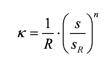 という関数で変化するものと定義し、また式中、sは曲線長さ、sRは転移曲線長さ、Rは回転搬送体のピッチ円半径、nは曲率変化の程度を表すパラメータである。
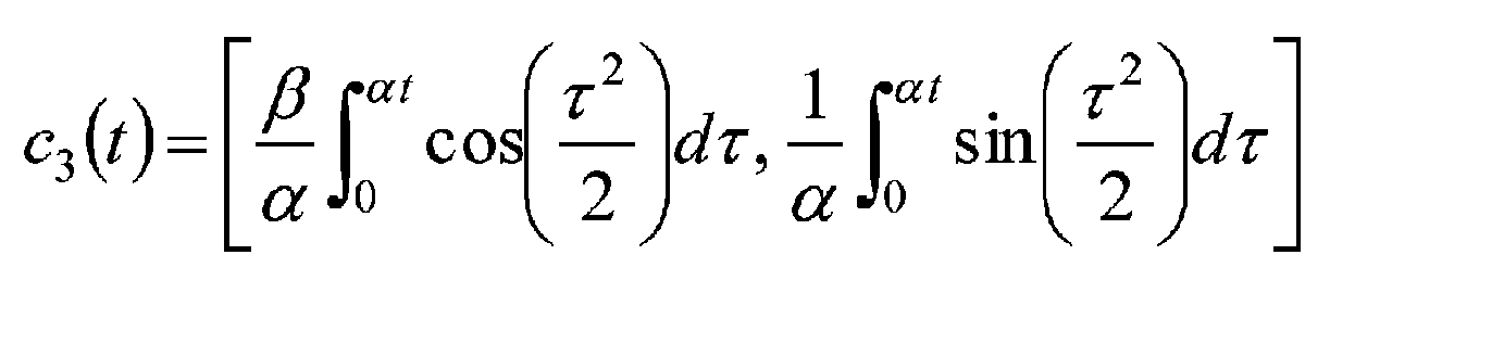
転移曲線c3は、数式3で表される。

式中、βは曲率変化の程度を表すパラメータであり、曲線長さsは数式3-1で求められる。
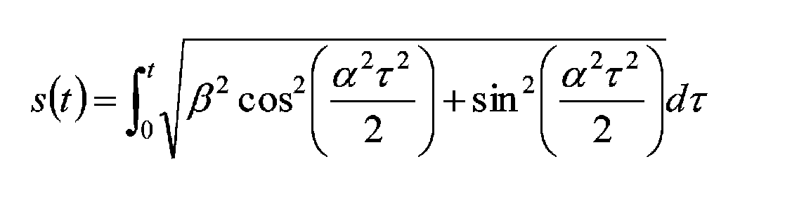
また曲線の曲率κは数式3-2で求められる。

数式3-1及び3-2から、曲率変化の程度を表すパラメータβの任意の値に対する、転移曲線長さと回転搬送体のピッチ円半径とからパラメータt及びαを決定することが出来る。従って数式3を用いて転移曲線c3を求めることが出来る。
転移曲線c4は、数式4で表される。

但し、転移曲線の曲率κが
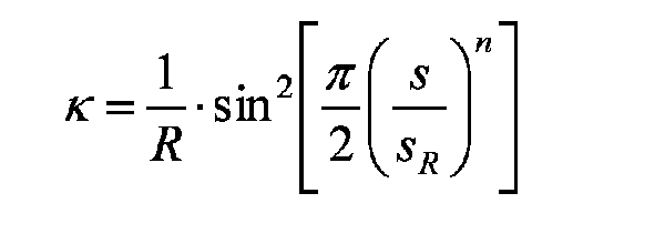 という関数で変化するものと定義し、また式中、sは曲線長さ(パラメータ)、sRは転移曲線長さ、Rは回転搬送体のピッチ円半径、nは曲率変化の程度を表すパラメータである。
前述した転移曲線c1~c4を、ピッチ円半径R1のシーミングターレット1とピッチ円半径R2のディスチャージターレット2間の円軌道から円軌道への受渡しの転移軌道に採用した場合の曲線に沿った長さに対する曲率の変化を図3(a)に示し、図3(b)にその時の速度が連続して変化する速度線図を示している。
本実施形態では、シーミングターレット1とディスチャージターレット2の設置は、従来と同様に、シーミングターレット1のピッチ円半径をR1とし、ディスチャージターレット2のピッチ円半径をR20としたとき、前記ターレットの軸心O1、O2間の距離Lが、L=R1+R20となるように設置されている。そして、シーミングターレット1からディスチャージターレット2への缶体の軸心が、前記した何れかの転移軌道に沿って移動するようにその転移曲線を、物品の大きさに応じてオフセットさせたオフセット転移曲線から成るガイド面のアウターガイド6とインナーガイド7を、缶体の直径D(ポケット嵌合位置)に対して間隔KがK≧Dとなるように設置されている。なお、本実施形態では、転移軌道の両側に沿ってアウターガイド6とインナーガイド7が設置されているが、必ずしも両側のガイドは必要なく、片側のみ或いは例えば転移軌道の半分をインナーガイドのみとし、他方の半分をアウターガイドのみとして設置することも可能である。
本実施形態では、シーミングターレット1とディスチャージターレット2の設置は、従来と同様に、シーミングターレット1のピッチ円半径をR1とし、ディスチャージターレット2のピッチ円半径をR20としたとき、前記ターレットの軸心O1、O2間の距離Lが、L=R1+R20となるように設置されている。そして、シーミングターレット1からディスチャージターレット2への缶体の軸心が、前記した何れかの転移軌道に沿って移動するようにその転移曲線を、物品の大きさに応じてオフセットさせたオフセット転移曲線から成るガイド面のアウターガイド6とインナーガイド7を、缶体の直径D(ポケット嵌合位置)に対して間隔KがK≧Dとなるように設置されている。なお、本実施形態では、転移軌道の両側に沿ってアウターガイド6とインナーガイド7が設置されているが、必ずしも両側のガイドは必要なく、片側のみ或いは例えば転移軌道の半分をインナーガイドのみとし、他方の半分をアウターガイドのみとして設置することも可能である。
図3に示すように、いずれの曲線もターレット1からの受渡し開始位置での曲率はターレット1の曲率1/R1から始まり、ディスチャージターレット2ヘの受渡し終了位置ではディスチャージターレット2の曲率(-1/R2)と一致し、その間を曲率が連続で変化する。その結果、缶体に加わる遠心加速度が連続で滑らかに変化し、衝撃が緩和される。また、シーミングターレット1の周速v1からディスチャージターレット2の周速v2へと連続で減速させて搬送方向加速度を連続で変化させる。
図3(a)の縦軸は曲率を表し、横軸は転移軌道(曲線)の長さを表している。また、図3(b)に搬送速度の変化を示しており、転移軌道ではシーミングターレット1での搬送速度v1からディスチャージターレット2での搬送速度v2まで滑らかに連続して減速させてディスチャージターレット2に受け渡していることがわかる。
なお、ターレット1の曲率1/R1から曲率ゼロとなるまでの間と、曲率ゼロからディスチャージターレット2の曲率(-1/R2)と一致するまでの間とで異なる転移曲線を用いることも出来る。例えば、ターレット1の曲率1/R1から曲率ゼロとなるまでの間は曲率が曲線の長さに比例して変化する転移曲線c1を用い、その後、曲率ゼロからディスチャージターレット2の曲率(-1/R2)と一致するまでの間は曲率が曲線の長さに対して曲線で変化する転移曲線c2を用いても良い。
図3(a)の縦軸は曲率を表し、横軸は転移軌道(曲線)の長さを表している。また、図3(b)に搬送速度の変化を示しており、転移軌道ではシーミングターレット1での搬送速度v1からディスチャージターレット2での搬送速度v2まで滑らかに連続して減速させてディスチャージターレット2に受け渡していることがわかる。
なお、ターレット1の曲率1/R1から曲率ゼロとなるまでの間と、曲率ゼロからディスチャージターレット2の曲率(-1/R2)と一致するまでの間とで異なる転移曲線を用いることも出来る。例えば、ターレット1の曲率1/R1から曲率ゼロとなるまでの間は曲率が曲線の長さに比例して変化する転移曲線c1を用い、その後、曲率ゼロからディスチャージターレット2の曲率(-1/R2)と一致するまでの間は曲率が曲線の長さに対して曲線で変化する転移曲線c2を用いても良い。
前記ディスチャージターレット2のポケット4は、ピッチ円半径R2が従来のピッチ円半径R20より小さい分、図1に示すように、その円弧状開口端部15、16をピッチ円半径R2より外方に突出して形成することができる。
なお、図1(b)における線図17はシーミングターレット1のポケット3から離れていく容器の軌跡を示し、ポケット3の中心を通る軸心O1に対するピッチ円との接線方向をxHとし、法線方向をyHとしている。同様に図1(c)における線図18はディスチャージターレット2のポケット4に入ってくる容器の軌跡を示し、ポケット4の中心を通る軸心O2に対するピッチ円との接線方向をxDとし、法線方向をyDとしている。これらによってそれぞれのターレットのポケット形状と、その円弧状開口端部の形状を決定することが出来る。
なお、本実施例では、物品の受渡しをより確実に行うためにディスチャージターレット2のポケット4の円弧状開口端部をピッチ円半径R2より外方に突出して形成したが、これに限るものではなく、シーミングターレット1のポケット3の円弧状開口端部を、そのピッチ円半径より外方に突出させても良く、また、両方のターレットポケットの円弧状開口端部を突出させても良い。
なお、図1(b)における線図17はシーミングターレット1のポケット3から離れていく容器の軌跡を示し、ポケット3の中心を通る軸心O1に対するピッチ円との接線方向をxHとし、法線方向をyHとしている。同様に図1(c)における線図18はディスチャージターレット2のポケット4に入ってくる容器の軌跡を示し、ポケット4の中心を通る軸心O2に対するピッチ円との接線方向をxDとし、法線方向をyDとしている。これらによってそれぞれのターレットのポケット形状と、その円弧状開口端部の形状を決定することが出来る。
なお、本実施例では、物品の受渡しをより確実に行うためにディスチャージターレット2のポケット4の円弧状開口端部をピッチ円半径R2より外方に突出して形成したが、これに限るものではなく、シーミングターレット1のポケット3の円弧状開口端部を、そのピッチ円半径より外方に突出させても良く、また、両方のターレットポケットの円弧状開口端部を突出させても良い。
以上のように、本発明によれば、円軌道から円軌道に搬送される過程における缶体に加わる加速度を、連続で、かつ円滑に変化させることが可能となる。この結果、高速生産において、従来にも増して安定した容器等の物品の搬送が可能となり、搬送ガイドとの接触等による変形、疵つきなどの不具合の発生を低減することができる。また、従来のターレット間の搬送装置において、ターレットの軸間距離を変更することなく、いずれか一方のターレットのピッチ円半径を小さくすることで構成され、既存の装置、設備を容易に改造することで達成できる。
なお、本実施形態においては、缶シーマのシーミングターレットとディスチャージターレット間に適用した場合について説明したが、本発明は前述した実施形態に限るものでなく、円軌道から円軌道への物品の受渡しとして、例えば缶体の製造ラインにおけるネッカー、トリマー等の種々の設備や、プラスチックボトル、紙容器等の製造ラインにおける種々のターレット間の物品の受け渡し搬送にも適用可能である。
なお、本実施形態においては、缶シーマのシーミングターレットとディスチャージターレット間に適用した場合について説明したが、本発明は前述した実施形態に限るものでなく、円軌道から円軌道への物品の受渡しとして、例えば缶体の製造ラインにおけるネッカー、トリマー等の種々の設備や、プラスチックボトル、紙容器等の製造ラインにおける種々のターレット間の物品の受け渡し搬送にも適用可能である。
本発明は、搬送物品に損傷を与えることなく、円軌道から円軌道への物品の受渡しを行う物品の搬送方法及び装置として産業上の利用可能性が高い。
Claims (9)
- 物品を回転搬送体間で円搬送から円搬送へ受渡す物品の搬送方法であって、前記回転搬送体のピッチ円同士が所定の間隙を有するように前記回転搬送体を設置し、両ピッチ円間を受渡し前の回転搬送体のピッチ円曲率から受け渡し後の回転搬送体のピッチ円曲率に、曲率が連続で変化する転移曲線に沿って前記物品を搬送することを特徴とする物品の搬送方法。
- 前記回転搬送体の隣り合うポケット間のサーキュラーピッチが互いに異なり、前記回転搬送体間の搬送速度が、受渡し前の円搬送の周速から受渡し後の円搬送の周速に連続で変化する請求項1に記載の物品の搬送方法。
- 前記回転搬送体の角速度の比が、それぞれの回転搬送体が有するポケット数の逆数に等しい請求項1に記載の物品の搬送方法。
- 前記回転搬送体間の搬送は、前記転移曲線をオフセットさせたオフセット転移曲線のガイド面を有する搬送ガイドに沿って搬送する請求項1に記載の物品の搬送方法。
- 前記転移曲線が、次の数式1~4の何れかで求まる曲線c1~c4の何れかである請求項1~4の何れかに記載の物品の搬送方法。


という関数で変化するものと定義し、また式中、s:曲線長さ、sR:転移曲線長さ、R:回転搬送体のピッチ円半径、n:曲率変化の程度を表すパラメータである。)


という関数で変化するものと定義し、また式中、s:曲線長さ(パラメータ)、sR:転移曲線長さ、R:回転搬送体のピッチ円半径、n:曲率変化の程度を表すパラメータである。)
- 物品を回転搬送体間で円搬送から円搬送へ受渡す物品の搬送装置であって、外周部に等ピッチでポケットが形成された受渡し側回転搬送体と、外周部に等ピッチでポケットが形成された受取り側回転搬送体とからなり、前記受渡し側回転搬送体と受取り側回転搬送体を、円搬送のピッチ円同士が所定の間隙を有するように離して設置し、この間を所定の軌道に沿って物品を搬送する搬送ガイドを設け、該搬送ガイドのガイド面形状が、受渡し前の円搬送のピッチ円曲率から受け渡し後の円搬送のピッチ円曲率に、曲率が連続で変化する転移曲線をオフセットさせたオフセット転移曲線であることを特徴とする物品の搬送装置。
- 前記受渡し側回転搬送体と前記受取り側回転搬送体は、両回転搬送体のピッチ円が互いに接して物品を受け渡す仮想回転搬送体の軸心位置を変更することなく、一方の回転搬送体のピッチ円半径を小さくし、前記回転搬送体間の搬送速度が、受渡し前の円搬送の周速から受渡し後の円搬送の周速に連続で変化し、前記受渡し側回転搬送体と前記受け取り側回転搬送体の角速度の比が、それぞれの回転搬送体に形成された前記ポケット数の逆数の比に等しい請求項6に記載の物品の搬送装置。
- 前記転移曲線が、次の数式1~4の何れかで求まる曲線c1~c4の何れかである請求項6又は7に記載の物品の搬送装置。


という関数で変化するものと定義し、また式中、s:曲線長さ、sR:転移曲線長さ、R:回転搬送体のピッチ円半径、n:曲率変化の程度を表すパラメータである。)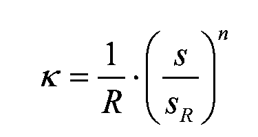


という関数で変化するものと定義し、また式中、s:曲線長さ(パラメータ)、sR:転移曲線長さ、R:回転搬送体のピッチ円半径、n:曲率変化の程度を表すパラメータである。)
- 前記回転搬送体のポケット形状は、円弧状開口端部がピッチ円より外方に延びる物品ガイド部であり、当該物品ガイド部形状及び前記ポケット形状が、受渡し前の円搬送の周速から受渡し後の円搬送の周速に搬送速度が連続で変化して搬送される物品に当接する形状である請求項8に記載の物品の搬送装置。
Priority Applications (3)
| Application Number | Priority Date | Filing Date | Title |
|---|---|---|---|
| CN201580039990.2A CN106573738B (zh) | 2014-08-08 | 2015-07-09 | 物品的搬送方法及其装置 |
| EP15829731.7A EP3178765A4 (en) | 2014-08-08 | 2015-07-09 | Article conveying method and device therefor |
| US15/426,248 US9969567B2 (en) | 2014-08-08 | 2017-02-07 | Method and device for conveying articles |
Applications Claiming Priority (2)
| Application Number | Priority Date | Filing Date | Title |
|---|---|---|---|
| JP2014163094A JP6424511B2 (ja) | 2014-08-08 | 2014-08-08 | 物品の搬送方法及びその装置 |
| JP2014-163094 | 2014-08-08 |
Related Child Applications (1)
| Application Number | Title | Priority Date | Filing Date |
|---|---|---|---|
| US15/426,248 Continuation US9969567B2 (en) | 2014-08-08 | 2017-02-07 | Method and device for conveying articles |
Publications (1)
| Publication Number | Publication Date |
|---|---|
| WO2016021364A1 true WO2016021364A1 (ja) | 2016-02-11 |
Family
ID=55263638
Family Applications (1)
| Application Number | Title | Priority Date | Filing Date |
|---|---|---|---|
| PCT/JP2015/069774 Ceased WO2016021364A1 (ja) | 2014-08-08 | 2015-07-09 | 物品の搬送方法及びその装置 |
Country Status (5)
| Country | Link |
|---|---|
| US (1) | US9969567B2 (ja) |
| EP (1) | EP3178765A4 (ja) |
| JP (1) | JP6424511B2 (ja) |
| CN (1) | CN106573738B (ja) |
| WO (1) | WO2016021364A1 (ja) |
Families Citing this family (7)
| Publication number | Priority date | Publication date | Assignee | Title |
|---|---|---|---|---|
| JP6802659B2 (ja) | 2016-07-29 | 2020-12-16 | 株式会社吉野工業所 | 液体収容容器の製造方法 |
| DE102017112220A1 (de) * | 2017-06-02 | 2018-12-27 | Khs Gmbh | Vorrichtung und Verfahren zum Transportieren von Behältern |
| DE102017129577A1 (de) * | 2017-12-12 | 2019-06-13 | Krones Ag | Vorrichtung und Verfahren zum Umformen von Kunststoffvorformlingen zu Kunststoffbehältnissen mit tangentialer Ausleitung der Kunststoffbehältnisse aus der Blasformmaschine |
| DE102018208956A1 (de) * | 2018-06-06 | 2019-12-12 | Bausch + Ströbel Maschinenfabrik Ilshofen GmbH + Co. KG | Weichenvorrichtung |
| DE102018211821A1 (de) * | 2018-07-17 | 2020-01-23 | Krones Ag | Verfahren zum Einteilen von Behältern auf eine Maschinenteilung und Behandlungsmaschine für Behälter |
| DE102019117377A1 (de) * | 2019-06-27 | 2020-12-31 | Khs Gmbh | Vorrichtung und Verfahren zum Transportieren von Behältern |
| DE102023128894A1 (de) * | 2023-10-20 | 2025-04-24 | Khs Gmbh | Vorrichtung zum Führen von Behältern, Transportsystem und Anlage |
Citations (2)
| Publication number | Priority date | Publication date | Assignee | Title |
|---|---|---|---|---|
| JPS58135027A (ja) * | 1981-10-17 | 1983-08-11 | クロネス・ア−ゲ−・ヘルマン・クロンセデル・マシ−ネンフアブリ−ク | 直立容器の分配装置 |
| JP2001287794A (ja) * | 2000-04-11 | 2001-10-16 | Toyo Seikan Kaisha Ltd | 充填装置 |
Family Cites Families (10)
| Publication number | Priority date | Publication date | Assignee | Title |
|---|---|---|---|---|
| JPS5827173B2 (ja) * | 1979-06-21 | 1983-06-08 | 株式会社 ロツテ | 板状物品の定量集積送出装置 |
| KR920011036B1 (ko) * | 1988-04-27 | 1992-12-26 | 호까이 세이칸 가부시끼가이샤 | 캔용기에 캔뚜껑을 말아서 단단히 조이는 장치 |
| CH687248A5 (de) * | 1991-10-30 | 1996-10-31 | Mitsubishi Heavy Ind Ltd | Dosenzufuehreinrichtung fuer eine Dosenverschliessmaschine. |
| JPH09142649A (ja) * | 1995-11-17 | 1997-06-03 | Toyo Seikan Kaisha Ltd | フィラーにおける容器送り装置 |
| US5772001A (en) * | 1996-04-18 | 1998-06-30 | B & H Manufacturing Company, Inc. | Star wheel system |
| DE102011115512A1 (de) * | 2011-10-11 | 2013-04-11 | Khs Gmbh | Transferstern |
| JP5630422B2 (ja) * | 2011-11-08 | 2014-11-26 | 東洋製罐株式会社 | 容器の処理装置 |
| CA2878328C (en) * | 2012-07-04 | 2017-07-11 | Daifuku Co., Ltd. | Transport conveyer and transport facility |
| EP2754556A1 (en) * | 2013-01-11 | 2014-07-16 | Crown Packaging Technology Inc | In-feed system and method for supplying can bodies to a decorator |
| JP6716858B2 (ja) * | 2015-01-15 | 2020-07-01 | 東洋製罐株式会社 | 缶体の充填巻締装置及び充填巻締方法 |
-
2014
- 2014-08-08 JP JP2014163094A patent/JP6424511B2/ja not_active Expired - Fee Related
-
2015
- 2015-07-09 CN CN201580039990.2A patent/CN106573738B/zh active Active
- 2015-07-09 WO PCT/JP2015/069774 patent/WO2016021364A1/ja not_active Ceased
- 2015-07-09 EP EP15829731.7A patent/EP3178765A4/en not_active Withdrawn
-
2017
- 2017-02-07 US US15/426,248 patent/US9969567B2/en active Active
Patent Citations (2)
| Publication number | Priority date | Publication date | Assignee | Title |
|---|---|---|---|---|
| JPS58135027A (ja) * | 1981-10-17 | 1983-08-11 | クロネス・ア−ゲ−・ヘルマン・クロンセデル・マシ−ネンフアブリ−ク | 直立容器の分配装置 |
| JP2001287794A (ja) * | 2000-04-11 | 2001-10-16 | Toyo Seikan Kaisha Ltd | 充填装置 |
Also Published As
| Publication number | Publication date |
|---|---|
| US9969567B2 (en) | 2018-05-15 |
| EP3178765A4 (en) | 2018-03-28 |
| JP2016037375A (ja) | 2016-03-22 |
| CN106573738B (zh) | 2019-07-30 |
| CN106573738A (zh) | 2017-04-19 |
| US20170152114A1 (en) | 2017-06-01 |
| JP6424511B2 (ja) | 2018-11-21 |
| EP3178765A1 (en) | 2017-06-14 |
Similar Documents
| Publication | Publication Date | Title |
|---|---|---|
| WO2016021364A1 (ja) | 物品の搬送方法及びその装置 | |
| CN102791598B (zh) | 容器制造 | |
| CN105050924B (zh) | 定向设备和方法 | |
| EP2845812B1 (en) | Packaging system | |
| EP3246258B1 (en) | Can filling/seaming device and can filling/seaming method | |
| CN214347609U (zh) | 用于涂覆容器的设备 | |
| CN101723293A (zh) | 用于输送容器的设备 | |
| US20100326793A1 (en) | Apparatus for feeding containers to a downstream processing unit | |
| US10376913B2 (en) | System for spraying the inside of can bodies | |
| US20120205218A1 (en) | Apparatus and method for treating containers with rotation of the containers | |
| JP6707562B2 (ja) | 物品をカールさせるための方法および装置 | |
| CN107934515A (zh) | 具有涂履站分路轮的容器生产设备 | |
| US7533511B2 (en) | Beverage bottling plant for filling bottles with a liquid beverage material having a packing machine and a rotation machine for rotating packed boxes | |
| JP6685210B2 (ja) | ボトルの搬送方法、スクリュー装置、及び、搬送装置 | |
| JP5321053B2 (ja) | 缶製造装置及び缶の製造方法 | |
| CN108137246A (zh) | 中间存储装置和用于中间存储的方法 | |
| JP7582975B2 (ja) | 特に製薬産業におけるボトルを充填する装置のための搬送方法及び搬送システム | |
| JP2006312492A (ja) | 製品箱詰め装置 | |
| JP3829578B2 (ja) | 充填装置 | |
| JP2018135179A (ja) | 搬送装置および搬送方法 | |
| US11760618B2 (en) | Container-processing device | |
| JP4348513B2 (ja) | 間欠回転ターレットへの円筒体供給方法および装置 | |
| JP2013056749A (ja) | グリップ式物品搬送装置 | |
| CN205099328U (zh) | 包装设备、灌装机、输瓶装置及其拨轮 | |
| EP3424681A1 (fr) | Dispositif de traitement de recipients et dispositif d'entrainement associe |
Legal Events
| Date | Code | Title | Description |
|---|---|---|---|
| 121 | Ep: the epo has been informed by wipo that ep was designated in this application |
Ref document number: 15829731 Country of ref document: EP Kind code of ref document: A1 |
|
| NENP | Non-entry into the national phase |
Ref country code: DE |
|
| REEP | Request for entry into the european phase |
Ref document number: 2015829731 Country of ref document: EP |
|
| WWE | Wipo information: entry into national phase |
Ref document number: 2015829731 Country of ref document: EP |