WO2016021503A1 - 静電紡糸用スピナレット - Google Patents
静電紡糸用スピナレット Download PDFInfo
- Publication number
- WO2016021503A1 WO2016021503A1 PCT/JP2015/071821 JP2015071821W WO2016021503A1 WO 2016021503 A1 WO2016021503 A1 WO 2016021503A1 JP 2015071821 W JP2015071821 W JP 2015071821W WO 2016021503 A1 WO2016021503 A1 WO 2016021503A1
- Authority
- WO
- WIPO (PCT)
- Prior art keywords
- spinneret
- raw material
- material fluid
- electrospinning
- discharge hole
- Prior art date
- Legal status (The legal status is an assumption and is not a legal conclusion. Google has not performed a legal analysis and makes no representation as to the accuracy of the status listed.)
- Ceased
Links
Images


Classifications
-
- D—TEXTILES; PAPER
- D01—NATURAL OR MAN-MADE THREADS OR FIBRES; SPINNING
- D01D—MECHANICAL METHODS OR APPARATUS IN THE MANUFACTURE OF ARTIFICIAL FILAMENTS, THREADS, FIBRES, BRISTLES OR RIBBONS
- D01D4/00—Spinnerette packs; Cleaning thereof
- D01D4/06—Distributing spinning solution or melt to spinning nozzles
-
- D—TEXTILES; PAPER
- D01—NATURAL OR MAN-MADE THREADS OR FIBRES; SPINNING
- D01D—MECHANICAL METHODS OR APPARATUS IN THE MANUFACTURE OF ARTIFICIAL FILAMENTS, THREADS, FIBRES, BRISTLES OR RIBBONS
- D01D5/00—Formation of filaments, threads, or the like
- D01D5/0007—Electro-spinning
- D01D5/0061—Electro-spinning characterised by the electro-spinning apparatus
- D01D5/0069—Electro-spinning characterised by the electro-spinning apparatus characterised by the spinning section, e.g. capillary tube, protrusion or pin
-
- B—PERFORMING OPERATIONS; TRANSPORTING
- B29—WORKING OF PLASTICS; WORKING OF SUBSTANCES IN A PLASTIC STATE IN GENERAL
- B29C—SHAPING OR JOINING OF PLASTICS; SHAPING OF MATERIAL IN A PLASTIC STATE, NOT OTHERWISE PROVIDED FOR; AFTER-TREATMENT OF THE SHAPED PRODUCTS, e.g. REPAIRING
- B29C48/00—Extrusion moulding, i.e. expressing the moulding material through a die or nozzle which imparts the desired form; Apparatus therefor
- B29C48/03—Extrusion moulding, i.e. expressing the moulding material through a die or nozzle which imparts the desired form; Apparatus therefor characterised by the shape of the extruded material at extrusion
- B29C48/05—Filamentary, e.g. strands
-
- B—PERFORMING OPERATIONS; TRANSPORTING
- B29—WORKING OF PLASTICS; WORKING OF SUBSTANCES IN A PLASTIC STATE IN GENERAL
- B29C—SHAPING OR JOINING OF PLASTICS; SHAPING OF MATERIAL IN A PLASTIC STATE, NOT OTHERWISE PROVIDED FOR; AFTER-TREATMENT OF THE SHAPED PRODUCTS, e.g. REPAIRING
- B29C48/00—Extrusion moulding, i.e. expressing the moulding material through a die or nozzle which imparts the desired form; Apparatus therefor
- B29C48/03—Extrusion moulding, i.e. expressing the moulding material through a die or nozzle which imparts the desired form; Apparatus therefor characterised by the shape of the extruded material at extrusion
- B29C48/07—Flat, e.g. panels
- B29C48/08—Flat, e.g. panels flexible, e.g. films
Definitions
- the present invention relates to a spinneret used for electrostatic spinning. More specifically, the present invention relates to a spinneret suitable for stabilization of continuous spinning with respect to a raw material fluid having a wide viscosity and homogenization of nanofiber quality.
- the ultrafine fiber “nanofiber” is a one-dimensional nanomaterial that has attracted attention in recent years. In a broad definition, it refers to a fiber having a diameter of 100 nm or less and an aspect ratio of 10 or more, but practically refers to a fiber having a diameter of 1000 nm or less (see Non-Patent Document 1).
- An electrostatic spinning method using electrostatic attraction is known as a method for producing nanofibers.
- a raw material fluid which is a spinning solution in which a polymer is dissolved
- a metal injection needle is charged with a high voltage together with a metal injection needle, and directed toward the grounded collection electrode surface from the tip of the injection needle.
- the raw material fluid is drawn in the direction of the surface of the collecting electrode to form a conical shape called a Taylor cone.
- the raw material fluid flies out as a jet from the tip of the Taylor cone, and the diameter becomes submicron with the volatilization of the solvent.
- the fibers of the order are collected in a non-woven form on the surface of the collecting electrode.
- the nanofibers produced by electrostatic spinning reported so far have a fiber diameter of at least about 100 nm. In the future, it is required to establish a manufacturing technique capable of mass production of nanofibers with smaller fiber diameters. In order to reduce the fiber diameter of the nanofibers produced by the electrospinning method, it is necessary to prevent the polymer chains in the raw material fluid from being entangled. For this purpose, it is effective to reduce the viscosity of the raw material fluid by reducing the polymer concentration of the raw material fluid or selecting a low molecular weight polymer (see Non-Patent Document 2).
- the viscosity of the raw material fluid is 5000 cP (centipoise) or more, and the raw material fluid having a viscosity lower than 5000 cP Is not preferred for spinning.
- the interval between adjacent injection needles is narrowed, the electric fields generated around the injection nozzles interfere with each other, making it difficult to spin nanofibers from all the injection needles, and the quality of the nanofibers may be reduced. is there.
- the present invention provides an electrospinning spinneret that can produce homogeneous nanofibers with small variations in fiber diameter using a raw material fluid having a wide range of viscosity from low viscosity to high viscosity.
- the present inventors use an electrospinning spinneret having a plurality of projections having a specific shape having discharge holes and a channel for distributing a raw material fluid. As a result, it was found that the problem can be solved, and the present invention has been completed.
- a spinneret for electrospinning composed of a structure of a conductive metal material, the structure having a major axis direction, a minor axis direction, and a thickness direction, and spinning on one surface of the structure.
- a plurality of protrusions are formed on the other surface so as to be aligned along the longitudinal direction, and each of the plurality of protrusions extends so as to protrude from the structure.
- An electrospinning spinneret having discharge holes for discharging a raw material fluid at the top thereof, and the pitch of the discharge holes exceeding 1 mm.
- the spinneret for electrospinning of the present invention has a plurality of protrusions and discharges the raw material fluid from the discharge holes drilled in each of the plurality of protrusions. Therefore, the raw material fluid having a wide range of viscosity from low viscosity to high viscosity is used. Thus, uniform and uniform nanofibers with small variations in fiber diameter can be produced with high productivity.
- the spinneret for electrospinning having a flow path inside is less susceptible to the difference in specific gravity between air and the raw material fluid, and can supply the raw material fluid to each discharge hole without embracing the air inside the spinneret. Therefore, stable discharge can be performed.
- an electrospinning spinneret that has a flow path inside and has a substantially equal distance from the inlet to each discharge hole can uniformly supply the raw material fluid to each discharge hole. Nanofiber can be obtained.
- the height of the protrusion is 0.1 mm or more, preferably 1 mm or more, spinning can be further stabilized.
- FIG. 1 is a perspective view of an electrospinning spinneret having a luminescent protrusion.
- FIG. 2 is a perspective view of an electrospinning spinneret in which adjacent projections are provided with radiant projections having different spinneret heights relative to the top 2 of the projections 5.
- FIG. 3 is a cross-sectional view of a light projection provided in an electrospinning spinneret.
- FIG. 4 is a cross-sectional view of an electrospinning spinneret having an internal space for storing a raw material fluid and components thereof.
- FIG. 5 is a perspective view of an internal space of an electrospinning spinneret having an internal space for storing a raw material fluid therein.
- FIG. 1 is a perspective view of an electrospinning spinneret having a luminescent protrusion.
- FIG. 2 is a perspective view of an electrospinning spinneret in which adjacent projections are provided with radiant projections having different spinneret heights
- FIG. 6 is a cross-sectional view of an electrospinning spinneret composed only of a raw material fluid passage and components thereof.
- FIG. 7 is a perspective view of a distribution plate for forming a flow path of the raw material fluid inside the electrospinning spinneret.
- FIG. 8 is a perspective view of an electrospinning spinneret corresponding to a top plate having a flow path, in which adjacent protrusions are provided with luminescent protrusions having different spinneret heights relative to the top 2 of the protrusions 5.
- FIG. 9 is a perspective view of an electrospinning spinneret having a quadrangular pyramid protrusion.
- FIG. 10 is a perspective view of an electrospinning spinneret having a quadrangular prism protrusion.
- FIG. 11 is a perspective view of an electrospinning spinneret having no protrusions.
- FIG. 1 is a perspective view of an electrospinning spinneret having a luminescent protrusion 5 (protrusion 5).
- the spinneret 1 for electrospinning of the present embodiment is a structure made of a conductive metal material.
- the structure includes a main body 20 formed in an X direction (also referred to as a major axis direction), a Y direction (also referred to as a thickness direction), and a Z direction (also referred to as a minor axis direction).
- a part of the metal material constituting the thickness direction (Y direction) extends so as to form the protrusion 5 along the minor axis direction (Z direction).
- a plurality of protrusions on the second surface (the other surface) 21 opposite to the first surface (one surface) 22 of the main body portion 20 of the structure (which constitutes one side surface of the main body portion 20). 5 is formed so as to extend along the minor axis direction (Z direction).
- the main body 20 means a portion obtained by removing the protrusion 5 from the structure constituting the spinneret 1 for electrospinning.
- the projection 5 has a top portion (projection top portion) 2 and a side surface portion 3, and each of the top portions 2 is provided with one discharge hole 4 for discharging the raw material fluid.
- a Taylor cone 7 made of a raw material fluid is formed in the vicinity of the discharge hole 4, and the nanofiber 8 is spun from the tip of the Taylor cone 7.
- the electrospinning spinneret 1 of the present embodiment has the protrusions 5 provided with the discharge holes 4, the electric charges are concentrated on the protrusions 5 of the electrospinning spinneret 1 charged at a high voltage, and around the protrusions 5. A strong electric field is generated. This strong electric field increases the force applied to the collector electrode surface applied to the Taylor cone 7 and suppresses the expansion of the Taylor cone 7 and the contact between adjacent Taylor cones.
- the spinneret 1 for electrostatic spinning has a configuration in which the protrusions 5 and the valleys 6 are alternately arranged along the long axis direction (X direction), so that the Taylor cone 7 extends along the side surfaces 3 and the valleys 6. Thus, it is difficult to expand to the adjacent protrusions 5, and contact between adjacent Taylor cones 7 is suppressed.
- the spinneret 1 for electrospinning only needs to be made of a conductive metal material, and may be any conductive metal material such as iron, aluminum, stainless steel, or brass. Moreover, you may be comprised from the combination and alloy of these several metal materials.
- the lengths of the major axis direction, the thickness direction, and the minor axis direction of the spinneret 1 for electrospinning can be arbitrarily selected.
- the major axis direction of the spinneret is 1500 mm or less
- the thickness direction of the spinneret is 100 mm or less
- the minor axis direction of the spinneret is 150 mm or less.
- the major axis direction and the uniaxial direction are referred to as different, but those having the same length in the width direction and the height direction of the spinneret are not excluded from the present invention.
- “Z direction is referred to as“ short axis direction ”and indicates the height direction of the spinneret”, and only the structure in which the protrusion 5 protrudes from the lower surface of the spinneret is illustrated.
- These spinnerets may be used so long as the projections 5 are directed from one side of the structure to the surface of the collecting electrode, and the projections 5 may be projected toward the ground. It may be used in a direction or upward. *
- the number of protrusions 5 included in the electrospinning spinneret 1 of the present embodiment is not particularly limited, but is preferably 1000 or less. By setting the number of protrusions 5 to 1000 or less, electrostatic repulsion between the Taylor cone 7 and the spun and charged nanofibers 8 hardly occurs, and the nanofibers 8 are spun uniformly.
- FIG. 2 is a perspective view of an electrospinning spinneret 1 in which the heights of the tops 2 of the protrusions 5 are different between adjacent protrusions.
- the spinneret 1 for electrospinning according to this embodiment is obtained by joining two parts, a top plate 30 and a nozzle 51.
- the lead hole 16 is provided in a pair with the discharge hole in order to guide the raw material fluid to the discharge hole, and generally has a large hole diameter for functional reasons in the manufacture of the spinneret.
- FIG. 3 is a cross-sectional view of the luminous element protrusion 5 (protrusion 5) of the electrospinning spinneret.
- FIG. 3 particularly shows an enlarged view of the protrusion 5 of the spinneret for electrospinning shown in FIG.
- the protrusion 5 of the spinneret for electrospinning in FIG. 2 has the same configuration as that shown in FIG.
- the height H (length in the H direction) of the protrusion 5 in the protrusion 5 of the spinneret 1 for electrospinning is not particularly limited, but is preferably 0.1 mm or more. Since the electric charge tends to concentrate on the pointed portion, the electric charge tends to concentrate on the tip of the protrusion 5. As a result, the electric field generated around the protrusion 5 becomes a stronger electric field than the spinneret without the protrusion 5 even at the same applied voltage, and the behavior of the Taylor cone 7 is stabilized. By setting the height of the protrusion 5 to 0.1 mm or more, a strong electric field is generated around the protrusion 5 and the force with which the Taylor cone 7 is attracted to the surface of the collecting electrode can be increased.
- the height of the protrusion 5 is more preferably 1 mm or more.
- the arrangement of the protrusions 5 of the electrospinning spinneret 1 of the present embodiment is not particularly limited, and may be arranged one-dimensionally depending on the shape and size of the electrospinning spinneret 1. Alternatively, it may be arranged two-dimensionally so as to be parallel to the surface of the collecting electrode. When the protrusions 5 are arranged one-dimensionally, the protrusions 5 that are adjacent to each other may have the same height as illustrated in FIG. 1, or the protrusions 5 that are adjacent as illustrated in FIG. You may arrange so that height may differ between.
- the height of the top 2 of the protrusion 5 (the first height of the protrusion 51 is increased as the protrusion 5 is arranged symmetrically with respect to the center of the nozzle 51 in the long axis direction and is arranged away from the center of the nozzle 51 in the long axis direction. It is preferable that the distance between the surface 22 and the top portion 2) be low so that a uniform electric field can be generated in each protrusion 5 and a uniform nanofiber 8 can be obtained. In addition, the case where the height of the top part of adjacent protrusions is the same may be included.
- the surface direction of the top 2 of the protrusions 5 of the present electrospinning spinneret is not particularly limited, but the surfaces of the tops 2 of all the protrusions 5 face the same surface direction. preferable.
- the shape of the protrusion 5 of the spinneret 1 for electrospinning of the present embodiment is not particularly limited, but considering the stability of the Taylor cone 7, the ease of processing the spinneret, the processing cost, etc.
- the shape is preferred.
- the projection 5 is not construed as being limited to the shape of the rectangular body, and various embodiments can be applied without departing from the gist of the polyhedron, hemisphere, cone, polygonal column, kamaboko, etc. can do. It is preferable that the plurality of protrusions 5 have substantially the same shape.
- the spinneret When performing electrospinning using the spinneret for electrospinning of the present invention, the spinneret is installed so that the projections are perpendicular to the collection surface, the raw material fluid is spun in the vertical direction, and the nanofibers are captured.
- a spinneret can be installed so that the protrusions are in the horizontal direction with respect to the collection surface, and the raw material fluid can be spun in the horizontal direction to collect the nanofibers.
- the shape of the discharge hole 4 of the electrospinning spinneret 1 of the present embodiment is not particularly limited, and any of circular, polygonal, star, Y, and C types can be selected. In consideration of ease of processing, a circular shape is more preferable.
- the plurality of ejection holes 4 preferably have substantially the same shape.
- the pitch P which is the distance between adjacent discharge holes of each discharge hole 4 shown in FIGS. 1 and 2, is set to exceed 1 mm. It forms so that it may align along the long axis direction (X direction) of a structure.
- the area of the top 2 (the area including the discharge hole) of the protrusion 5 of the electrospinning spinneret 1 of the present embodiment is not particularly limited, but is preferably in the range of 0.1 to 100 mm 2 .
- the Taylor cone 7 can be reliably held, and the expansion to the periphery of the Taylor cone 7 and the contact between adjacent Taylor cones 7 can be suppressed.
- the pitch P can be reduced, and sufficient productivity of the nanofibers 8 can be maintained.
- a more preferable area of the top 2 is in the range of 1 to 50 mm 2 .
- the hole diameter of the discharge hole 4 of the present embodiment is not limited, but is preferably 0.1 mm to 1.0 mm. It is preferable to set the diameter of the discharge hole 4 to 0.1 mm or more because the washing performance of the spinneret for electrospinning is improved. Further, by setting the hole diameter of the discharge hole 4 to 1.0 mm or less, the Taylor cone 7 exhibits a stable behavior in the case of a low-viscosity raw material fluid or a low discharge amount, and the nanofibers 8 are spun uniformly. Therefore, it is preferable.
- the position of the discharge hole 4 arranged in the top 2 of the spinneret 1 for electrospinning of the present embodiment is not particularly limited, as long as it is arranged in the top 2, and the center of the surface of the top 2 or Although an outer periphery etc. can be illustrated, it is preferable to arrange
- FIG. 4 is a cross-sectional view of an electrospinning spinneret having an internal space for storing a raw material fluid therein.
- the electrospinning spinneret 1 of the present embodiment is obtained by joining two parts, a top plate 30 and a nozzle 40.
- the components constituting the electrospinning spinneret 1 are not limited to such a form.
- a raw material fluid for spinning is supplied from the inlet 10 provided on the first surface 22.
- the raw material fluid supplied from the inflow port 10 is stored in the internal space 9 inside the spinneret, and is perforated on the bottom surface of the internal space 9 and discharged from the discharge hole 4 penetrating through the protrusion 5.
- the internal space 9 functions as a buffer, the raw material fluid is uniformly discharged from each discharge hole. Further, since the spinneret structure is simple, the washing process and maintenance after spinning can be easily performed.
- the supply method of the raw material fluid to the spinneret 1 for electrospinning of the present embodiment is not particularly limited, and examples thereof include a gear pump, a syringe pump, and supply by pressurizing the solution.
- the gear pump is difficult to maintain because it requires time for disassembly and cleaning, but has an advantage that the raw material fluid can be continuously supplied.
- the syringe pump is a batch type, and the amount of raw material fluid that can be supplied at a time is limited, but it is possible to supply raw material fluid having a wider range of viscosity than the gear pump. It can be appropriately selected according to the raw material fluid to be used, the production amount, and maintainability.
- FIG. 5 is a perspective view of the internal space of an electrospinning spinneret having an internal space for storing a raw material fluid therein.
- the volume of the internal space 9 and the area and length of the discharge hole 4 of the electrospinning spinneret 1 of the present embodiment are defined as A, the cross-sectional area perpendicular to the major axis direction of the spinneret in the internal space 9
- the length of the spinneret in the space 9 in the major axis direction is B
- the cross-sectional area of the discharge hole 4 is a
- the length of the discharge hole 4 (the length through the nozzle from the internal space 9 to the outlet of the discharge hole) is b
- the number of ejection holes 4 perforated on the bottom surface of one internal space 9 is n, it is preferable to satisfy the relationship of the following formula (1).
- the fluidity of the raw material fluid in the length direction of the discharge hole 4 is in the long axis direction of the internal space 9. Therefore, the back pressure inside the spinneret 1 for electrospinning is increased, the raw material fluid is easily supplied uniformly to the respective discharge holes 4, and the nanofibers 8 are easily spun.
- FIG. 6 is an example of a cross-sectional view of an electrospinning spinneret having a flow path for a raw material fluid and its components.
- the electrospinning spinneret 1 of the present embodiment can supply the raw material fluid to the plurality of discharge holes 4 from the inlet 10.
- an internal space 9 may be included, but it is preferable to have a plurality of flow paths 11 branched to distribute the fluid. .
- the raw material fluid has a higher specific gravity than air in the process of filling the internal space 9 with the raw material fluid. It is difficult to uniformly supply the raw material fluid to the respective discharge holes 4 while being filled.
- the raw material fluid can be filled without embracing air in the internal space 9, without embracing air in the internal space 9, the distance from the inlet 10 to each discharge hole is different, and the raw material fluid can be uniformly supplied to each discharge hole 4.
- Have difficulty. By forming the flow path 11 inside the electrospinning spinneret 1, it is possible to make it less susceptible to the difference in specific gravity between the air and the raw material fluid. Thereby, the raw material fluid can be filled in the internal space 9 without embracing the air inside the spinneret, and further, since the distance from the inlet to each discharge hole is substantially equal, The discharge holes 4 can be supplied uniformly, and a uniform nanofiber 8 can be obtained.
- the difference in distance from the inlet 10 to each discharge hole 4, that is, the difference in the distance between each flow path 11 is that the raw material fluid can be uniformly supplied to each discharge hole 4. It is preferably within 10%. By making the difference in distance from the inlet 10 to each discharge hole 4 within 10%, the difference in back pressure applied to each discharge hole 4 is small, and the discharge amount of the raw material fluid from each discharge hole 4 is reduced. The influence of the difference on the nanofiber 8 can be suppressed.
- the shape of the flow path 11 of this embodiment is not specifically limited, as a result of analyzing the relationship between the shape of the flow path 11 and the flow of the raw material fluid, the raw material fluid can be efficiently and uniformly supplied to each discharge hole 4. In view of being able to do so, it is preferable to have the shape of a branch diagram as illustrated in FIG. Further, as shown in the lower half of FIG. 6, the electrospinning spinneret 1 according to the present embodiment joins a total of four parts including two distribution plates 12 and 15 in addition to the top plate 30 and the nozzle 40. Is obtained. A flow path 11 is formed in each component and on the joint surface, and the flow path 11 can be easily formed.
- FIG. 7 is a perspective view of the distribution plates 12 and 15 for having a flow path of the raw material fluid inside the spinneret 1 for electrospinning.
- the distribution plate 12 has a groove 13 formed by excavating the surface (joint surface) and a hole 14 penetrating in the thickness direction of the distribution plate 12 in the groove, so that manufacture and spinneret cleaning are facilitated. Used for.
- the flow path 11 can be formed by installing the distribution plate 12, and the spinneret cleaning process can be easily and effectively performed by disassembling the nozzle 40 and the distribution plates 12 and 15 after spinning.
- the distribution plate 15 By preparing a plurality of distribution plates (for example, the distribution plate 15) having different shapes of grooves and holes of the distribution plate 12, it can be replaced with a distribution plate 12 suitable for the viscosity of the raw material fluid as needed. It can handle a wide range of raw material fluids.
- the volume of the groove of the distribution plate and the area and length of the hole penetrating the groove are D, the sectional area of the groove 13 of the distribution plate perpendicular to the direction in which the raw material fluid flows, and the hole penetrating the groove of the distribution plate.
- D can efficiently supply the raw material fluid to each discharge hole 4 efficiently. It is preferable that 0.1 to 5 mm 2 and d be in the range of 0.1 to 1 mm 2 .
- the low-viscosity raw material fluid does not entrap air, and the high-viscosity raw material fluid does not have excessively increased back pressure.
- the raw material fluid is easily supplied uniformly to the discharge holes 4 and the spinning of the nanofibers 8 is likely to be uniform.
- the distribution plate 15 has two grooves 13a and 13b formed by excavating the surface. Holes 14a and 14b penetrating the distribution plate 15 in the thickness direction are provided in the groove 13a, and holes 14c and 14d are provided in the groove 13b. Each of the grooves 13a and 13b of the distribution plate 15 preferably satisfies the above range for the same reason as D, L, d, and l in the distribution plate 12.
- FIG. 8 is a perspective view of an electrospinning spinneret 1 using a top plate 31 having a flow path.
- the spinneret 1 for electrospinning of the present embodiment is obtained by joining two parts, a top plate 30 and a nozzle 52.
- a top plate 31 having a flow path as illustrated in FIG. 8 may be used.
- the number of parts can be reduced as compared with the case where a distribution plate is used, and the washing process and maintenance after spinning can be easily performed.
- the material contained in the raw material fluid is not particularly limited and can be appropriately selected.
- Such materials include polyester, nylon, polyurethane, polyvinylidene fluoride, polyacrylonitrile, polyimide, polyamide, polysulfone, polyethersulfone, polyvinyl alcohol, polystyrene, polymethyl methacrylate, alumina, Examples thereof include inorganic materials such as titanium oxide. It can be appropriately selected in consideration of the effect that appears when nanofibers are formed.
- these polymers may be used independently and may mix and use 2 or more types of polymers. Furthermore, these polymers may be combined with other functional materials.
- Such functional materials include functional materials such as flame retardants, deodorants, antioxidants, antistatic agents, and pigments.
- Other examples include nanomaterials such as gold nanoparticles, titanium dioxide nanoparticles, hydroxyapatite nanoparticles, carbon nanotubes, and graphene.
- the solvent contained in the raw material fluid is not particularly limited, and a solvent capable of dissolving the polymer at room temperature or under heating is appropriately selected. can do.
- solvents include N, N-dimethylformamide, N, N-dimethylacetamide, N-methyl-2-pyrrolidone, tetrahydrofuran, tetramethylurea, trimethyl phosphate, 1,1,1,3,3,3 -Hexafluoro-2-propanol, hexafluoroacetic acid, methyl ethyl ketone, dimethyl sulfoxide, acetone, butyl acetate, cyclohexane, butyrolactone, tetraethyl urea, isophorone, triethyl phosphate, carbitol acetate, propylene carbonate, etc.
- solvents may be used alone or in combination of two or more solvents.
- the volatility of the polymer solution in the electrospinning process can be controlled by mixing a highly volatile solvent and a less volatile solvent. preferable. Examples of such combinations include N, N-dimethylformamide and acetone, N, N-dimethylacetamide and acetone, N-methyl-2-pyrrolidone and acetone.
- the mixing ratio in the case of using a mixture of two or more kinds of solvents is not particularly limited, taking into consideration the physical properties of the polymer solution to be sought, such as concentration and viscosity, volatility, conductivity, surface tension, etc. It can be adjusted appropriately. This makes it possible to easily control the fiber diameter and fiber form of the resulting nanofiber 8, and also makes it easy to adjust the solution discharge amount during electrostatic spinning. For example, the nanofiber 8 can be produced by increasing the discharge amount. Can improve the performance.
- an additive can be added for the purpose of adjusting the characteristics of the raw material fluid.
- the kind of additive is not particularly limited, and an organic or inorganic salt can be appropriately selected.
- an ionic surfactant is added, the surface tension of the raw material fluid is reduced and the electrical conductivity is improved, so that the raw material fluid to which no ionic surfactant is added is electrostatically spun.
- nanofibers 8 having a small number of spherical particles (beads) and a small average fiber diameter can be obtained.
- the amount of the additive added is not particularly limited, and can be appropriately selected according to the desired effect of adjusting the characteristics of the raw material fluid.
- a preferable range is 0.005 to 0.5 mass in the raw material fluid.
- 0.01 to 0.3% by mass in the raw material fluid can be exemplified.
- the polymer concentration of the raw material fluid is not particularly limited, and the viscosity of the raw material fluid, and the nanofiber 8 obtained by the electrospinning.
- the average fiber diameter, fiber form, and productivity can be appropriately adjusted, but a preferable concentration range is 3 to 30% by mass, and a more preferable range is 4 to 25% by mass. Can do.
- nanofibers 8 having a sufficiently small average fiber diameter in which a bead structure is not often seen can be obtained with satisfactory productivity, and if it is 4% by mass or more, A nanofiber 8 with a satisfactory average fiber diameter in which a bead structure is hardly seen is more preferable because it can be obtained with sufficient productivity.
- the polymer concentration is 30% by mass or less, the viscosity is suitable for electrospinning, and the nanofiber 8 can be obtained with stable spinnability, and if it is 25% by mass or less, more stable spinnability is obtained. Therefore, it is more preferable.
- the viscosity of the raw material fluid is not particularly limited, and is preferably in the range of 10 to 5000 cP, and in the range of 30 to 3000 cP. More preferably.
- the viscosity of the raw material fluid is 10 cP or more, the spinnability is good and the beads are hardly developed.
- the viscosity of the raw material fluid is 5000 cP or less, since the viscosity is low, it is easy to supply the raw material fluid to each discharge hole 4 of the spinneret 1 for electrostatic spinning.
- the spinneret 1 for electrospinning according to the present embodiment has a discharge hole 4 in the protrusion 5, the Taylor cone 7 exhibits a stable behavior due to a strong electric field generated around the protrusion 5.
- a low-viscosity raw material fluid having a viscosity of 10 to 200 cP it is possible to produce nanofibers 8 having a uniform and thin fiber diameter.
- Viscosity of raw material fluid The viscosity of the raw material fluid described below was measured using a viscometer RVDV-IPPrime manufactured by BROOKFIELD and a cone spindle CPE-41 under the conditions of a temperature of 25 ° C. and a humidity of 30%.
- the nanofibers were observed using a scanning electron microscope SU8020 manufactured by Hitachi High-Technologies Corporation, and the diameters of 50 nanofibers were measured using image analysis software. The average value of the fiber diameters at 50 nanofibers was defined as the average fiber diameter.
- Solef 21216 a polyvinylidene fluoride-hexafluoropropylene (PVDF-HFP) resin manufactured by Solvay, was dissolved in N, N-dimethylformamide at a concentration of 8% by mass, and sodium lauryl sulfate as an additive was 0.1% by mass.
- the raw material fluid was prepared.
- the viscosity of this raw material fluid was 461 cP.
- the raw material fluid is electrostatically spun using the spinneret for electrostatic spinning having the protrusions shown in FIG. PVDF-HFP nanofibers were prepared.
- the length of the spinneret is 100 mm, the thickness of the spinneret is 20 mm, the height of the spinneret is 40 mm, the height of the protrusion is 1.5 mm, the shape of the protrusion is a phosphor, and the protrusion is one-dimensionally arranged and discharged.
- the shape of the hole outlet is circular, the hole diameter of the outlet of the discharge hole is 0.3 mm, the top area (including the area of the outlet of the discharge hole) is 1 mm 2 , one discharge hole is arranged per projection, and four spinnerets The distance between adjacent discharge holes was 8 mm, and the hole diameter at the inlet was 2 mm.
- the spinneret for electrospinning according to the present embodiment has an internal space as illustrated in FIG.
- the spinning conditions of this example are: the supply amount of the raw material fluid to one discharge hole (single hole) is 1.0 mL / hr, the applied voltage is 45 kV, the spinning distance is 150 mm, the spinning space has an air temperature of 25 degrees C and humidity 30%.
- the viscosity of the raw material fluid was high, it was possible to perform stable spinning for 2 hours or more without contact between adjacent Taylor cones.
- sufficient quality PVDF-HFP nanofibers were obtained.
- the average fiber diameter of the obtained PVDF-HFP nanofiber was 78 ⁇ 15 nm.
- Example 2 Solef 21216, a Solvay PVDF-HFP resin, was dissolved in N, N-dimethylformamide at a concentration of 6% by mass, and sodium lauryl sulfate was added as an additive to a concentration of 0.1% by mass.
- the viscosity of this raw material fluid was 162 cP.
- the raw material fluid is electrospun under the same spinning conditions as in Example 1 using the same electrospinning spinneret as in Example 1, and PVDF -HFP nanofibers were made.
- the viscosity of the raw material fluid is low, a strong electric field is generated around the projections of the phosphor, and the force that attracts the Taylor cone to the surface of the collecting electrode can be increased. Stable spinning was possible over 2 hours without contact with each other, and the operability was sufficient. However, since there was no flow path for distributing the raw material fluid inside the spinneret and nanofiber spinning from the Taylor cone was intermittent, sufficient quality PVDF-HFP nanofibers could not be obtained. .
- the average fiber diameter of the obtained PVDF-HFP nanofiber was 62 ⁇ 25 nm.
- Example 3 The raw material fluid was prepared under the same conditions as in Example 2. Next, using the aluminum sheet placed on the collecting electrode as a base material, the raw material fluid is electrostatically spun using the spinneret for electrostatic spinning having the protrusions shown in FIG. PVDF-HFP nanofibers were prepared.
- the length of the spinneret is 100 mm, the thickness of the spinneret is 20 mm, the height of the spinneret is 40 mm, the height of the protrusion is 1.5 mm, the shape of the protrusion is a phosphor, and the protrusion is one-dimensionally arranged, the outlet of the discharge hole
- the shape of the nozzle is circular, the diameter of the outlet of the discharge hole is 0.3 mm, the top area (including the area of the outlet of the discharge hole) is 1 mm 2 , one discharge hole is arranged for each protrusion, and the spinneret has four protrusions
- the distance between adjacent discharge holes was 8 mm, and the hole diameter of the inlet was 2 mm.
- a tournament-like flow path as illustrated in FIG. 6 is provided in the perspective view of FIG. 7 in order to distribute the raw material fluid from the inlet to each discharge hole. It was formed using a distribution plate as illustrated.
- the cross-sectional area of the distribution plate groove perpendicular to the direction in which the raw material fluid flows is 2 mm 2
- the length of the groove in the direction in which the raw material fluid flows is 35 mm
- the area of the hole penetrating the distribution plate groove is 0.5 mm 2.
- the length of the hole penetrating the distribution plate groove was 3 mm.
- the spinning conditions in this example were the same as those in Example 1.
- the viscosity of the raw material fluid is low, a strong electric field is generated around the projections of the phosphor, and the force that attracts the Taylor cone to the surface of the collecting electrode can be increased. Stable spinning was possible over 2 hours without contact with each other, and the operability was sufficient.
- a flow path for distributing the raw material fluid was provided inside the spinneret, and the spinning of nanofibers from the Taylor cone was continuous, so that sufficient quality PVDF-HFP nanofibers were obtained.
- the average fiber diameter of the obtained PVDF-HFP nanofiber was 64 ⁇ 13 nm.
- Example 4 The raw material fluid was prepared under the same conditions as in Example 2. The viscosity of this raw material fluid was 162 cP. Next, using the aluminum sheet placed on the collecting electrode as a base material, the raw material fluid is electrostatically spun using the spinneret for electrostatic spinning having the protrusions shown in FIG. PVDF-HFP nanofibers were prepared.
- the length of the spinneret is 100 mm, the thickness of the spinneret is 20 mm, the height of the spinneret is 40 mm, the height of the projection is 1.5 mm, the shape of the projection is a square weight, the projection is arranged one-dimensionally, and the discharge hole
- the shape of the outlet is circular, the diameter of the outlet of the discharge hole is 0.3 mm, the area of the top (including the area of the outlet of the discharge hole) is 1 mm 2 , one discharge hole is arranged per projection, and the spinneret has four
- the distance between adjacent ejection holes was 8 mm, and the hole diameter of the inlet was 2 mm.
- the spinneret for electrospinning according to the present embodiment has an internal space as illustrated in FIG.
- the spinning conditions in this example were the same as those in Example 1.
- a strong electric field is generated around the projections of the phosphor, and the force that attracts the Taylor cone to the surface of the collecting electrode can be increased. Stable spinning was possible over 2 hours without contact with each other, and the operability was sufficient.
- the average fiber diameter of the obtained PVDF-HFP nanofiber was 58 ⁇ 26 nm.
- Example 5 The raw material fluid was prepared under the same conditions as in Example 2. The viscosity of this raw material fluid was 162 cP. Next, PVDF-HFP nanofibers were produced using an aluminum sheet as a base material and the raw material fluid thereon using the spinneret for electrospinning having protrusions shown in FIG.
- the length of the spinneret is 100 mm, the thickness of the spinneret is 20 mm, the height of the spinneret is 40 mm, the height of the projection is 1.5 mm, the shape of the projection is a square weight, the projection is arranged one-dimensionally, and the discharge hole
- the outlet shape is circular, the outlet hole diameter is 0.3 mm, one discharge hole is provided for each protrusion, the spinneret has four protrusions, and the distance between adjacent discharge holes is 8 mm.
- the hole diameter was 2 mm.
- a tournament-shaped flow path as illustrated in FIG. 6 is provided in the perspective view of FIG. 7 in order to distribute the raw material fluid from the inlet to each discharge hole.
- the cross-sectional area of the distribution plate groove perpendicular to the direction in which the raw material fluid flows is 2 mm 2
- the length of the groove in the direction in which the raw material fluid flows is 35 mm
- the area of the hole penetrating the distribution plate groove is 0.5 mm 2.
- the length of the hole penetrating the distribution plate groove was 3 mm.
- the spinning conditions in this example were the same as those in Example 1.
- the spinning conditions in this example were the same as those in Example 1.
- the viscosity of the raw material fluid is low, a strong electric field is generated around the projections of the phosphor, and the force that attracts the Taylor cone to the surface of the collecting electrode can be increased.
- Example 6 The raw material fluid was prepared under the same conditions as in Example 2. The viscosity of this raw material fluid was 162 cP. Next, PVDF-HFP nanofibers were produced using an aluminum sheet as a base material and the raw material fluid thereon using the spinneret for electrospinning having protrusions shown in FIG.
- the length of the spinneret is 100 mm, the thickness of the spinneret is 20 mm, the height of the spinneret is 40 mm, the height of the protrusion is 1.5 mm, the shape of the protrusion is a square pillar, the protrusion is one-dimensionally arranged, and the discharge hole
- the outlet shape is circular, the outlet hole diameter is 0.3 mm, one discharge hole is provided for each protrusion, the spinneret has four protrusions, and the distance between adjacent discharge holes is 8 mm.
- the hole diameter was 2 mm.
- the spinneret for electrospinning according to the present embodiment has an internal space as illustrated in FIG. 4 in order to distribute the raw material fluid from the inlet to each discharge hole.
- the length of the internal space was 80 mm, the thickness of the internal space was 10 mm, the height of the internal space was 35 mm, and the length of the discharge hole was 5 mm.
- the spinning conditions in this example were the same as those in Example 1.
- a strong electric field is generated around the projections of the phosphor, and the force that attracts the Taylor cone to the surface of the collecting electrode can be increased.
- Stable spinning was possible over 2 hours without contact with each other, and the operability was sufficient.
- the average fiber diameter of the obtained PVDF-HFP nanofiber was 65 ⁇ 28 nm.
- Example 7 The raw material fluid was prepared under the same conditions as in Example 2. The viscosity of this raw material fluid was 162 cP. Next, PVDF-HFP nanofibers were produced using an aluminum sheet as a base material and the raw material fluid thereon using the spinneret for electrospinning having protrusions shown in FIG.
- the length of the spinneret is 100 mm, the thickness of the spinneret is 20 mm, the height of the spinneret is 40 mm, the height of the protrusion is 1.5 mm, the shape of the protrusion is a square pillar, the protrusion is one-dimensionally arranged, and the discharge hole
- the shape of the hole is circular, the hole diameter at the outlet of the discharge hole is 0.3 mm, one discharge hole is provided for each protrusion, the spinneret has four protrusions, and the top area (including the area of the discharge hole outlet) was 1 mm 2 , the distance between adjacent discharge holes was 8 mm, and the hole diameter of the inlet was 2 mm.
- a tournament-shaped flow path as illustrated in FIG. 6 is provided in the perspective view of FIG. 7 in order to distribute the raw material fluid from the inlet to each discharge hole. It was formed using a distribution plate as illustrated.
- the cross-sectional area of the distribution plate groove perpendicular to the direction in which the raw material fluid flows is 2 mm 2
- the length of the groove in the direction in which the raw material fluid flows is 35 mm
- the area of the hole penetrating the distribution plate groove is 0.5 mm 2.
- the length of the hole penetrating the distribution plate groove was 3 mm.
- the spinning conditions in this example were the same as those in Example 1.
- the spinning conditions in this example were the same as those in Example 1.
- the viscosity of the raw material fluid is low, a strong electric field is generated around the projections of the phosphor, and the force that attracts the Taylor cone to the surface of the collecting electrode can be increased. Stable spinning was possible over 2 hours without contact with each other, and the operability was sufficient.
- a flow path for distributing the raw material fluid was provided inside the spinneret, and the spinning of nanofibers from the Taylor cone was continuous, so that sufficient quality PVDF-HFP nanofibers were obtained.
- the average fiber diameter of the obtained PVDF-HFP nanofiber was 62 ⁇ 19 nm.
- Example 1 The raw material fluid was prepared under the same conditions as in Example 2. The viscosity of this raw material fluid was 162 cP. Next, an aluminum sheet was prepared as a base material, and a PVDF-HFP nanofiber was prepared on the raw material fluid using the electrospinning spinneret having no protrusions as shown in FIG. The length of the spinneret is 100 mm, the thickness of the spinneret is 20 mm, the height of the spinneret is 40 mm, the discharge holes are arranged one-dimensionally, the shape of the discharge holes is circular, and the diameter of the outlet of the discharge holes is 0.3 mm. The spinneret had four discharge holes, and the distance between adjacent discharge holes was 8 mm.
- the spinneret for electrospinning of this comparative example has an internal space as illustrated in FIG. 4 in order to distribute the raw material fluid from the inlet to each discharge hole.
- the length of the internal space was 80 mm
- the thickness of the internal space was 10 mm
- the height of the internal space was 35 mm
- the length of the discharge hole was 5 mm.
- the spinning conditions of this comparative example were the same spinning conditions as in Example 1.
- the viscosity of the raw material fluid is low and a spinneret without protrusions is used, the force of attracting the Taylor cone to the surface of the collecting electrode could not be sufficiently increased, so electrostatic spinning was started. Ten minutes after that, the adjacent Taylor cones were in contact with each other, and sufficient operability could not be satisfied.
- PVDF-HFP nanofibers of sufficient quality could not be obtained.
- the average fiber diameter of the obtained PVDF-HFP nanofiber was 65 ⁇ 33 nm.
- the raw material fluid was prepared under the same conditions as in Example 2.
- the viscosity of this raw material fluid was 162 cP.
- an aluminum sheet was prepared as a base material, and a PVDF-HFP nanofiber was prepared on the raw material fluid using the electrospinning spinneret having no protrusions as shown in FIG.
- the length of the spinneret is 100 mm
- the thickness of the spinneret is 20 mm
- the height of the spinneret is 40 mm
- the discharge holes are arranged one-dimensionally
- the shape of the discharge holes is circular
- the diameter of the outlet of the discharge holes is 0.3 mm.
- the spinneret had four discharge holes, and the distance between adjacent discharge holes was 8 mm.
- a tournament-shaped flow path as illustrated in FIG. 6 is provided in the perspective view of FIG. 7 in order to distribute the raw material fluid from the inlet to each discharge hole. It was formed using a distribution plate as illustrated.
- the cross-sectional area of the distribution plate groove perpendicular to the direction in which the raw material fluid flows is 2 mm 2
- the length of the groove in the direction in which the raw material fluid flows is 35 mm
- the area of the hole penetrating the distribution plate groove is 0.5 mm 2.
- the length of the hole penetrating the distribution plate groove was 3 mm.
- the spinning conditions of this comparative example were the same spinning conditions as in Example 1.
Landscapes
- Engineering & Computer Science (AREA)
- Mechanical Engineering (AREA)
- Textile Engineering (AREA)
- Spinning Methods And Devices For Manufacturing Artificial Fibers (AREA)
- Nonwoven Fabrics (AREA)
Abstract
Description
[1]導電性金属材料の構造体より構成される静電紡糸用スピナレットであって、該構造体は、長軸方向と短軸方向と厚み方向とを備え、該構造体の一面に紡糸用の原料流体の流入口を備え、他の一面に、複数の突起が前記長軸方向に沿って並ぶように形成され、複数の突起の各々は該構造体から突出するように延び、該突起は、その頂部に原料流体を吐出する吐出孔を有し、該吐出孔のピッチが1mmを越える静電紡糸用スピナレット。
[2]前記突起の高さが0.1mm以上である前記[1]に記載の静電紡糸用スピナレット。
[3]前記構造体が2個以上の部品で構成され、該部品の接合面に、各吐出孔に原料流体を均一に分配する流路を有する前記[1]または[2]に記載の静電紡糸用スピナレット。
[4]前記構造体の本体部の内部に設けられた、各吐出孔に原料流体を均一に分配する分配板を有し、当該分配板が原料流体の流路を形成する前記[1]~[3]のいずれか1に記載の静電紡糸用スピナレット。
[5]前記流入口から各々の吐出孔までは略等距離の流路で繋がっており、前記流入口から各々の吐出孔までの流路の距離の差が10%以内である前記[1]~[4]のいずれか1に記載の静電紡糸用スピナレット。
該構造体において、その厚み方向(Y方向)を構成する前記金属材料の一部が短軸方向(Z方向)に沿って突起5を形成するように延びている。言い換えると、構造体の本体部20の第一の面(一面)22と対向する逆側の第二の面(他の一面)21(本体部20の一側面を構成する)において、複数の突起5が短軸方向(Z方向)に沿って伸びるように形成されている。ここで本体部20は、静電紡糸用スピナレット1を構成する構造体から突起5を除いた部分を意味する。

静電紡糸用スピナレット1の内部に流路11を形成することで、空気と原料流体の比重の差の影響を受けにくくすることができる。これにより、スピナレット内部に空気を抱き込むことなく原料流体を内部空間9に充填することができ、さらに流入口から各々の吐出孔までの距離が略等距離であることから、原料流体を各々の吐出孔4に均一に供給することができ、均一なナノファイバ8を得ることができる。
気温25℃および湿度30%の条件でBROOKFIELD社製の粘度計RVDV-IPrimeと、コーンスピンドルCPE-41を使用して、後述する原料流体の粘度を測定した。
株式会社日立ハイテクノロジーズ製の走査型電子顕微鏡SU8020を使用して、ナノファイバを観察し、画像解析ソフトを用いてナノファイバ50ヶ所の直径を測定した。ナノファイバ50ヶ所の繊維径の平均値を平均繊維径とした。
静電紡糸を開始して、隣接するテイラーコーン同士が接触することなく2時間以上経過し、テイラーコーンからのナノファイバの紡出が連続的であった場合を「◎」、隣接するテイラーコーン同士が接触することなく2時間以上経過したが、テイラーコーンからのナノファイバの紡出が断続的であった場合を「○」、隣接するテイラーコーン同士が接触するまでに要した時間が10分~2時間の範囲であり、テイラーコーンからのナノファイバの紡出が連続的または断続的であった場合を「△」、隣接するテイラーコーン同士が接触するまでに要した時間が10分以下であり、テイラーコーンからのナノファイバの紡出が連続的または断続的であった場合を「×」として紡糸安定性を評価した。
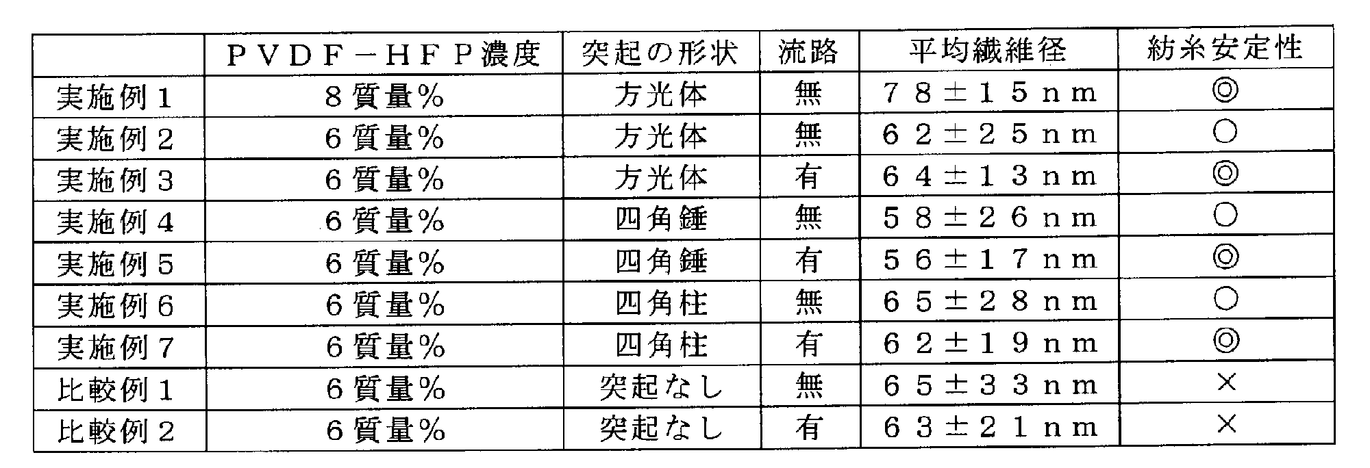
Solvay製のポリフッ化ビニリデン-ヘキサフルオロプロピレン(PVDF-HFP)樹脂であるSolef 21216を、N,N-ジメチルホルムアミドに8質量%の濃度で溶解し、添加剤としてラウリル硫酸ナトリウムを0.1質量%となるように添加し、原料流体を調製した。この原料流体の粘度は461cPであった。次に、捕集電極の上に置いたアルミシートを基材として、この上に前記原料流体を、図1に記載の突起を有する静電紡糸用スピナレットを用いて、静電紡糸をして、PVDF-HFPナノファイバを作製した。なお、スピナレットの長さは100mm、スピナレットの厚さは20mm、スピナレットの高さは40mm、突起の高さは1.5mm、突起の形状は方光体、突起は一次元的に配され、吐出孔出口の形状は円形、吐出孔の出口の孔径は0.3mm、頂部の面積(吐出孔出口の面積を含む)は1mm2、1つの突起につき1つの吐出孔を配し、スピナレットは4個の突起を有し、隣り合う吐出孔間の距離は8mm、流入口の孔径は2mmであった。本実施例の静電紡糸用スピナレットは、その内部に、原料流体を流入口から各々の吐出孔へ分配するため、図4に例示するような内部空間を形成している。内部空間の長さは80mm、内部空間の厚さは10mm、内部空間の高さは35mm、吐出孔の長さは5mmであった。本実施例の紡糸条件は、1個の吐出孔(単孔)への原料流体の供給量は1.0mL/hr、印加電圧は45kV、紡糸距離は150mm、紡糸空間は気温25度Cおよび湿度30%であった。本実施例では、原料流体の粘度が高いため、隣接するテイラーコーン同士が接触することなく2時間以上に亘って安定的な紡糸が可能であったため、十分な操業性であった。また、テイラーコーンからのナノファイバの紡出が連続的であったため、十分な品質のPVDF-HFPナノファイバを得られた。得られたPVDF-HFPナノファイバの平均繊維径は、78±15nmであった。
Solvay製のPVDF-HFP樹脂であるSolef 21216を、N,N-ジメチルホルムアミドに6質量%の濃度で溶解し、添加剤としてラウリル硫酸ナトリウムを0.1質量%となるように添加し、原料流体を調製した。この原料流体の粘度は162cPであった。次に、アルミシートを基材として、この上に前記原料流体を、実施例1と同様の静電紡糸用スピナレットを用いて、実施例1と同様の紡糸条件で静電紡糸をして、PVDF-HFPナノファイバを作製した。本実施例では、原料流体の粘度が低いが、方光体の突起の周辺に強力な電界を発生させ、テイラーコーンが捕集電極表面へ引き寄せられる力を強めることができたため、隣接するテイラーコーン同士が接触することなく2時間以上に亘って安定的な紡糸が可能で十分な操業性であった。しかし、スピナレットの内部に原料流体を分配する流路を有しておらず、テイラーコーンからのナノファイバの紡出が断続的であったため、十分な品質のPVDF-HFPナノファイバを得られなかった。得られたPVDF-HFPナノファイバの平均繊維径は、62±25nmであった。
原料流体は実施例2と同様の条件で調製した。次に、捕集電極の上に置いたアルミシートを基材として、この上に前記原料流体を、図1に記載の突起を有する静電紡糸用スピナレットを用いて、静電紡糸をして、PVDF-HFPナノファイバを作製した。スピナレットの長さは100mm、スピナレットの厚さは20mm、スピナレットの高さは40mm、突起の高さは1.5mm、突起の形状は方光体、突起は一次元的に配され、吐出孔出口の形状は円形、吐出孔の出口の孔径は0.3mm、頂部の面積(吐出孔出口の面積を含む)は1mm2、1つの突起につき1つの吐出孔を配し、スピナレットは4個の突起を有し、隣り合う吐出孔間の距離は8mm、流入口の孔径は2mmであった。本実施例の静電紡糸用スピナレットは、その内部に、原料流体を流入口から各々の吐出孔へ分配するため、図6に例示するようなトーナメント状の流路を、図7の斜視図に例示するような分配板を用いて形成した。原料流体が流れる方向に対して垂直方向の分配板の溝の断面積は2mm2、原料流体が流れる方向の溝の長さは35mm、分配板の溝を貫通する孔の面積は0.5mm2、分配板の溝を貫通する孔の長さは3mmであった。本実施例の紡糸条件は、実施例1と同様の紡糸条件であった。本実施例では、原料流体の粘度が低いが、方光体の突起の周辺に強力な電界を発生させ、テイラーコーンが捕集電極表面へ引き寄せられる力を強めることができたため、隣接するテイラーコーン同士が接触することなく2時間以上に亘って安定的な紡糸が可能で十分な操業性であった。また、スピナレットの内部に原料流体を分配する流路を有しており、テイラーコーンからのナノファイバの紡出が連続的であったため、十分な品質のPVDF-HFPナノファイバを得られた。得られたPVDF-HFPナノファイバの平均繊維径は、64±13nmであった。
原料流体は実施例2と同様の条件で調製した。この原料流体の粘度は162cPであった。次に、捕集電極の上に置いたアルミシートを基材として、この上に前記原料流体を、図9に記載の突起を有する静電紡糸用スピナレットを用いて、静電紡糸をして、PVDF-HFPナノファイバを作製した。なお、スピナレットの長さは100mm、スピナレットの厚さは20mm、スピナレットの高さは40mm、突起の高さは1.5mm、突起の形状は四角錘、突起は一次元的に配され、吐出孔出口の形状は円形、吐出孔の出口の孔径は0.3mm、頂部の面積(吐出孔出口の面積を含む)は1mm2、1つの突起につき1つの吐出孔を配し、スピナレットは4個の突起を有し、隣り合う吐出孔間の距離は8mm、流入口の孔径は2mmであった。本実施例の静電紡糸用スピナレットは、その内部に、原料流体を流入口から各々の吐出孔へ分配するため、図4に例示するような内部空間を形成している。内部空間の長さは80mm、内部空間の厚さは10mm、内部空間の高さは35mm、吐出孔の長さは5mmであった。本実施例の紡糸条件は、本実施例1と同様の紡糸条件であった。本実施例では、原料流体の粘度が低いが、方光体の突起の周辺に強力な電界を発生させ、テイラーコーンが捕集電極表面へ引き寄せられる力を強めることができたため、隣接するテイラーコーン同士が接触することなく2時間以上に亘って安定的な紡糸が可能で十分な操業性であった。しかし、スピナレットの内部に原料流体を分配する流路を有しておらず、テイラーコーンからのナノファイバの紡出が断続的であったため、十分な品質のPVDF-HFPナノファイバを得られなかった。得られたPVDF-HFPナノファイバの平均繊維径は、58±26nmであった。
原料流体は実施例2と同様の条件で調製した。この原料流体の粘度は162cPであった。次に、アルミシートを基材として、この上に前記原料流体を、図9に記載の突起を有する静電紡糸用スピナレットを用いて、PVDF-HFPナノファイバを作製した。なお、スピナレットの長さは100mm、スピナレットの厚さは20mm、スピナレットの高さは40mm、突起の高さは1.5mm、突起の形状は四角錘、突起は一次元的に配され、吐出孔出口の形状は円形、吐出孔の出口の孔径0.3mm、1つの突起につき1つの吐出孔を配し、スピナレットは4個の突起を有し、隣り合う吐出孔間の距離は8mm、流入口の孔径2mmであった。本実施例の静電紡糸用スピナレットは、その内部に、原料流体を流入口から各々の吐出孔へ分配するため、図6に例示するようなトーナメント形状の流路を、図7の斜視図に例示するような分配板を用いて形成した。原料流体が流れる方向に対して垂直方向の分配板の溝の断面積は2mm2、原料流体が流れる方向の溝の長さは35mm、分配板の溝を貫通する孔の面積は0.5mm2、分配板の溝を貫通する孔の長さは3mmであった。本実施例の紡糸条件は、実施例1と同様の紡糸条件であった。本実施例の紡糸条件は、実施例1と同様の紡糸条件であった。本実施例では、原料流体の粘度が低いが、方光体の突起の周辺に強力な電界を発生させ、テイラーコーンが捕集電極表面へ引き寄せられる力を強めることができたため、隣接するテイラーコーン同士が接触することなく2時間以上に亘って安定的な紡糸が可能で十分な操業性であった。また、スピナレットの内部に原料流体を分配する流路を有しており、テイラーコーンからのナノファイバの紡出が連続的であったため、十分な品質のPVDF-HFPナノファイバを得られた。得られたPVDF-HFPナノファイバの平均繊維径は、56±17nmであった。
原料流体は実施例2と同様の条件で調製した。この原料流体の粘度は162cPであった。次に、アルミシートを基材として、この上に前記原料流体を、図10に記載の突起を有する静電紡糸用スピナレットを用いて、PVDF-HFPナノファイバを作製した。なお、スピナレットの長さは100mm、スピナレットの厚さは20mm、スピナレットの高さは40mm、突起の高さは1.5mm、突起の形状は四角柱、突起は一次元的に配され、吐出孔出口の形状は円形、吐出孔の出口の孔径0.3mm、1つの突起につき1つの吐出孔を配し、スピナレットは4個の突起を有し、隣り合う吐出孔間の距離は8mm、流入口の孔径2mmであった。本実施例の静電紡糸用スピナレットは、その内部に、原料流体を流入口から各々の吐出孔へ分配するため、図4に例示するような内部空間を形成している。内部空間の長さは80mm、内部空間の厚さは10mm、内部空間の高さは35mm、吐出孔の長さは5mmであった。本実施例の紡糸条件は、実施例1と同様の紡糸条件であった。本実施例では、原料流体の粘度が低いが、方光体の突起の周辺に強力な電界を発生させ、テイラーコーンが捕集電極表面へ引き寄せられる力を強めることができたため、隣接するテイラーコーン同士が接触することなく2時間以上に亘って安定的な紡糸が可能で十分な操業性であった。しかし、スピナレットの内部に原料流体を分配する流路を有しておらず、テイラーコーンからのナノファイバの紡出が断続的であったため、十分な品質のPVDF-HFPナノファイバを得られなかった。得られたPVDF-HFPナノファイバの平均繊維径は、65±28nmであった。
原料流体は実施例2と同様の条件で調製した。この原料流体の粘度は162cPであった。次に、アルミシートを基材として、この上に前記原料流体を、図10に記載の突起を有する静電紡糸用スピナレットを用いて、PVDF-HFPナノファイバを作製した。なお、スピナレットの長さは100mm、スピナレットの厚さは20mm、スピナレットの高さは40mm、突起の高さは1.5mm、突起の形状は四角柱、突起は一次元的に配され、吐出孔の形状は円形、吐出孔の出口の孔径は0.3mm、1つの突起につき1つの吐出孔を配し、スピナレットは4個の突起を有し、頂部の面積(吐出孔出口の面積を含む)は1mm2、隣り合う吐出孔間の距離は8mm、流入口の孔径は2mmであった。本実施例の静電紡糸用スピナレットは、その内部に、原料流体を流入口から各々の吐出孔へ分配するため、図6に例示するようなトーナメント形状の流路を、図7の斜視図に例示するような分配板を用いて形成した。原料流体が流れる方向に対して垂直方向の分配板の溝の断面積は2mm2、原料流体が流れる方向の溝の長さは35mm、分配板の溝を貫通する孔の面積は0.5mm2、分配板の溝を貫通する孔の長さは3mmであった。本実施例の紡糸条件は、実施例1と同様の紡糸条件であった。本実施例の紡糸条件は、実施例1と同様の紡糸条件であった。本実施例では、原料流体の粘度が低いが、方光体の突起の周辺に強力な電界を発生させ、テイラーコーンが捕集電極表面へ引き寄せられる力を強めることができたため、隣接するテイラーコーン同士が接触することなく2時間以上に亘って安定的な紡糸が可能で十分な操業性であった。また、スピナレットの内部に原料流体を分配する流路を有しており、テイラーコーンからのナノファイバの紡出が連続的であったため、十分な品質のPVDF-HFPナノファイバを得られた。得られたPVDF-HFPナノファイバの平均繊維径は、62±19nmであった。
原料流体は実施例2と同様の条件で調製した。この原料流体の粘度は162cPであった。次に、アルミシートを基材として準備し、この上に前記原料流体を、図11に記載の突起を有していない静電紡糸用スピナレットを用いて、PVDF-HFPナノファイバを作製した。なお、スピナレットの長さは100mm、スピナレットの厚さは20mm、スピナレットの高さは40mm、吐出孔は一次元的に配され、吐出孔の形状は円形、吐出孔の出口の孔径は0.3mm、スピナレットは4個の吐出孔を有し、隣り合う吐出孔間の距離は8mmであった。本比較例の静電紡糸用スピナレットは、その内部に、原料流体を流入口から各々の吐出孔へ分配するため、図4に例示するような内部空間を形成している。内部空間の長さは80mm、内部空間の厚さは10mm、内部空間の高さは35mm、吐出孔の長さは5mmであった。本比較例の紡糸条件は、実施例1と同様の紡糸条件であった。本比較例では、原料流体の粘度が低く、突起を有していないスピナレットを用いており、テイラーコーンが捕集電極表面へ引き寄せられる力を十分に強めることができなかったため、静電紡糸を開始してから10分後に隣接するテイラーコーン同士が接触してしまい、十分な操業性を満足することができなかった。また、スピナレットの内部に原料流体を分配する流路を有しておらず、テイラーコーンからのナノファイバの紡出が連続的であったため、十分な品質のPVDF-HFPナノファイバを得られなかった。得られたPVDF-HFPナノファイバの平均繊維径は、65±33nmであった。
原料流体は実施例2と同様の条件で調製した。この原料流体の粘度は162cPであった。次に、アルミシートを基材として準備し、この上に前記原料流体を、図11に記載の突起を有していない静電紡糸用スピナレットを用いて、PVDF-HFPナノファイバを作製した。なお、スピナレットの長さは100mm、スピナレットの厚さは20mm、スピナレットの高さは40mm、吐出孔は一次元的に配され、吐出孔の形状は円形、吐出孔の出口の孔径は0.3mm、スピナレットは4個の吐出孔を有し、隣り合う吐出孔間の距離は8mmであった。本実施例の静電紡糸用スピナレットは、その内部に、原料流体を流入口から各々の吐出孔へ分配するため、図6に例示するようなトーナメント形状の流路を、図7の斜視図に例示するような分配板を用いて形成した。原料流体が流れる方向に対して垂直方向の分配板の溝の断面積は2mm2、原料流体が流れる方向の溝の長さは35mm、分配板の溝を貫通する孔の面積は0.5mm2、分配板の溝を貫通する孔の長さは3mmであった。本比較例の紡糸条件は、実施例1と同様の紡糸条件であった。本比較例では、原料流体の粘度が低く、突起を有していないスピナレットを用いており、テイラーコーンが捕集電極表面へ引き寄せられる力を十分に強めることができなかったため、静電紡糸を開始してから10分後に隣接するテイラーコーン同士が接触してしまい、十分な操業性を満足することができなかった。しかし、スピナレットの内部に原料流体を分配する流路を有しており、テイラーコーンからのナノファイバの紡出が連続的であったため、十分な品質のPVDF-HFPナノファイバを得られた。得られたPVDF-HFPナノファイバの平均繊維径は、63±21nmであった。
2 頂部(突起頂部)
3 側面部
4 吐出孔
5 突起
6 谷部
7 テイラーコーン
8 ナノファイバ
9 内部空間
10 流入口
11 流路
12 分配板
13、13a、13b 分配板の溝
14a、14b、14c、14d 分配板の孔
15 分配板
16 リード孔
20 本体部
21 第二の面(一面)
22 第一の面(他の一面)
30 トッププレート
31 流路を有するトッププレート
40、51、52 ノズル
X 構造体の長手方向、または幅方向に沿った長軸方向
Y 構造体の厚みの方向に沿った厚み方向
Z 構造体の短手方向、または高さ方向に沿った短軸方向
P ピッチ
H 突起の高さ
Claims (5)
- 導電性金属材料の構造体より構成される静電紡糸用スピナレットであって、
該構造体は、長軸方向と短軸方向と厚み方向とを備え、
該構造体の一面に紡糸用の原料流体の流入口を備え、他の一面に、複数の突起が前記長軸方向に沿って並ぶように形成され、複数の突起の各々は該構造体から突出するように延び、該突起は、その頂部に原料流体を吐出する吐出孔を有し、該吐出孔のピッチが1mmを越える静電紡糸用スピナレット。 - 前記突起の高さが0.1mm以上である請求項1に記載の静電紡糸用スピナレット。
- 前記構造体が2個以上の部品で構成され、該部品の接合面に、各吐出孔に原料流体を均一に分配する流路を有する請求項1または2に記載の静電紡糸用スピナレット。
- 前記構造体の本体部の内部に設けられた、各吐出孔に原料流体を均一に分配する分配板を有し、当該分配板が原料流体の流路を形成する請求項1~3のいずれか1項に記載の静電紡糸用スピナレット。
- 前記流入口から各々の吐出孔までは略等距離の流路で繋がっており、前記流入口から各々の吐出孔までの流路の距離の差が10%以内である請求項1~4のいずれか1項に記載の静電紡糸用スピナレット。
Priority Applications (4)
| Application Number | Priority Date | Filing Date | Title |
|---|---|---|---|
| US15/501,437 US10662553B2 (en) | 2014-08-05 | 2015-07-31 | Spinneret for electrostatic spinning |
| KR1020177005148A KR20170038014A (ko) | 2014-08-05 | 2015-07-31 | 정전 방사용 방적 돌기 |
| EP15829614.5A EP3178973A4 (en) | 2014-08-05 | 2015-07-31 | Spinneret for electrostatic spinning |
| CN201580051170.5A CN107109703B (zh) | 2014-08-05 | 2015-07-31 | 静电纺纱用喷丝头 |
Applications Claiming Priority (4)
| Application Number | Priority Date | Filing Date | Title |
|---|---|---|---|
| JP2014-159715 | 2014-08-05 | ||
| JP2014159715 | 2014-08-05 | ||
| JP2015-098719 | 2015-05-14 | ||
| JP2015098719A JP6699093B2 (ja) | 2014-08-05 | 2015-05-14 | 静電紡糸用スピナレット |
Publications (1)
| Publication Number | Publication Date |
|---|---|
| WO2016021503A1 true WO2016021503A1 (ja) | 2016-02-11 |
Family
ID=55263770
Family Applications (1)
| Application Number | Title | Priority Date | Filing Date |
|---|---|---|---|
| PCT/JP2015/071821 Ceased WO2016021503A1 (ja) | 2014-08-05 | 2015-07-31 | 静電紡糸用スピナレット |
Country Status (6)
| Country | Link |
|---|---|
| US (1) | US10662553B2 (ja) |
| EP (1) | EP3178973A4 (ja) |
| JP (1) | JP6699093B2 (ja) |
| KR (1) | KR20170038014A (ja) |
| CN (1) | CN107109703B (ja) |
| WO (1) | WO2016021503A1 (ja) |
Cited By (1)
| Publication number | Priority date | Publication date | Assignee | Title |
|---|---|---|---|---|
| CN115976661A (zh) * | 2023-02-27 | 2023-04-18 | 青岛大学 | 一种静电纺丝装置 |
Families Citing this family (7)
| Publication number | Priority date | Publication date | Assignee | Title |
|---|---|---|---|---|
| KR102019224B1 (ko) * | 2018-12-28 | 2019-09-06 | (주) 엠에이케이 | 전기 방사 장치 |
| US12209330B1 (en) * | 2019-07-10 | 2025-01-28 | American Nano Llc | Electrospinning apparatus and methods |
| CN110747522B (zh) * | 2019-10-31 | 2020-08-25 | 东华大学 | 一种均匀供液的静电纺丝装置 |
| CN110725018B (zh) * | 2019-11-07 | 2020-05-19 | 吉林大学 | 一种用于静电纺丝的仿生防堵塞喷丝头 |
| JP7588984B2 (ja) * | 2020-08-18 | 2024-11-25 | 株式会社東芝 | 電界紡糸ヘッド、電界紡糸装置及び電界紡糸方法 |
| CN113564735A (zh) * | 2021-08-20 | 2021-10-29 | 北京化工大学 | 一种气流辅助的离心静电纺丝装置 |
| CN116716668B (zh) * | 2023-08-09 | 2023-12-22 | 江苏新视界先进功能纤维创新中心有限公司 | 一种熔融静电纺丝装置及采用其制备纳米纤维长丝的方法 |
Citations (6)
| Publication number | Priority date | Publication date | Assignee | Title |
|---|---|---|---|---|
| JPS6375107A (ja) * | 1986-09-19 | 1988-04-05 | Toray Ind Inc | 多成分繊維紡糸用口金装置 |
| JP2005534828A (ja) * | 2002-08-16 | 2005-11-17 | サンシン クリエーション カンパニーリミテッド | 電気紡糸法を用いたナノ繊維製造装置及びこれに採用される紡糸ノズルパック |
| WO2007069381A1 (ja) * | 2005-12-12 | 2007-06-21 | Matsushita Electric Industrial Co., Ltd. | 静電噴霧装置及び静電噴霧方法 |
| JP2007303031A (ja) * | 2006-05-12 | 2007-11-22 | Kato Tech Kk | エレクトロスピニグ用ノズル及びそれを用いた微細熱可塑性樹脂繊維の製造方法 |
| JP2008174867A (ja) * | 2007-01-18 | 2008-07-31 | Matsushita Electric Ind Co Ltd | 高分子ファイバ生成方法と装置、これらを用いた高分子ウエブ製造方法と装置 |
| WO2011142355A1 (ja) * | 2010-05-10 | 2011-11-17 | 独立行政法人物質・材料研究機構 | 高分子ファイバーとその製造方法および製造装置 |
Family Cites Families (18)
| Publication number | Priority date | Publication date | Assignee | Title |
|---|---|---|---|---|
| US2323025A (en) * | 1939-05-13 | 1943-06-29 | Formhals Anton | Production of artificial fibers from fiber forming liquids |
| US3034526A (en) * | 1959-11-13 | 1962-05-15 | Du Pont | Laminar fluid flow process |
| IT941066B (it) * | 1971-06-19 | 1973-03-01 | Jenne S R L | Cella modulare per la filatura di fibre sintetiche |
| US4550681A (en) * | 1982-10-07 | 1985-11-05 | Johannes Zimmer | Applicator for uniformly distributing a flowable material over a receiving surface |
| US20020094352A1 (en) * | 2000-11-14 | 2002-07-18 | Ying Guo | Bicomponent filament spin pack used in spunbond production |
| US7014442B2 (en) * | 2002-12-31 | 2006-03-21 | Kimberly-Clark Worldwide, Inc. | Melt spinning extrusion head system |
| US7175407B2 (en) * | 2003-07-23 | 2007-02-13 | Aktiengesellschaft Adolph Saurer | Linear flow equalizer for uniform polymer distribution in a spin pack of a meltspinning apparatus |
| US7762801B2 (en) * | 2004-04-08 | 2010-07-27 | Research Triangle Institute | Electrospray/electrospinning apparatus and method |
| JP2006152479A (ja) | 2004-11-29 | 2006-06-15 | Toray Ind Inc | 極細繊維の製造装置およびそれを用いた製造方法 |
| DE102005053248B4 (de) * | 2005-11-08 | 2016-12-01 | Axel Nickel | Schmelzblaskopf mit veränderbarer Spinnbreite |
| DE112008000379T5 (de) * | 2007-02-21 | 2010-01-07 | Panasonic Corporation, Kadoma-shi | Nanofaser-Herstellungseinrichtung |
| JP4833238B2 (ja) * | 2007-03-27 | 2011-12-07 | ジョン−チョル パック | ナノファイバーの大量生産のための電気紡糸装置 |
| CN101215762A (zh) | 2008-01-03 | 2008-07-09 | 东华大学 | 高效连续式静电纺纳米纤维毡的制备装置和方法 |
| CA2748248C (en) * | 2008-12-25 | 2016-11-01 | Kuraray Co., Ltd. | Filter materials and filter cartridges |
| JP4763845B2 (ja) | 2009-09-09 | 2011-08-31 | パナソニック株式会社 | ナノファイバ製造装置、ナノファイバ製造方法 |
| CN101871130B (zh) * | 2010-07-06 | 2011-08-10 | 北京化工大学 | 一种一字架静电纺丝喷头 |
| CN102181946A (zh) * | 2011-05-13 | 2011-09-14 | 杨恩龙 | 装有圆锥形辅助电极的多喷头静电纺丝装置 |
| JP5821714B2 (ja) | 2012-03-09 | 2015-11-24 | 東レ株式会社 | 複合口金および複合繊維の製造方法 |
-
2015
- 2015-05-14 JP JP2015098719A patent/JP6699093B2/ja active Active
- 2015-07-31 WO PCT/JP2015/071821 patent/WO2016021503A1/ja not_active Ceased
- 2015-07-31 US US15/501,437 patent/US10662553B2/en active Active
- 2015-07-31 EP EP15829614.5A patent/EP3178973A4/en not_active Withdrawn
- 2015-07-31 KR KR1020177005148A patent/KR20170038014A/ko not_active Withdrawn
- 2015-07-31 CN CN201580051170.5A patent/CN107109703B/zh active Active
Patent Citations (6)
| Publication number | Priority date | Publication date | Assignee | Title |
|---|---|---|---|---|
| JPS6375107A (ja) * | 1986-09-19 | 1988-04-05 | Toray Ind Inc | 多成分繊維紡糸用口金装置 |
| JP2005534828A (ja) * | 2002-08-16 | 2005-11-17 | サンシン クリエーション カンパニーリミテッド | 電気紡糸法を用いたナノ繊維製造装置及びこれに採用される紡糸ノズルパック |
| WO2007069381A1 (ja) * | 2005-12-12 | 2007-06-21 | Matsushita Electric Industrial Co., Ltd. | 静電噴霧装置及び静電噴霧方法 |
| JP2007303031A (ja) * | 2006-05-12 | 2007-11-22 | Kato Tech Kk | エレクトロスピニグ用ノズル及びそれを用いた微細熱可塑性樹脂繊維の製造方法 |
| JP2008174867A (ja) * | 2007-01-18 | 2008-07-31 | Matsushita Electric Ind Co Ltd | 高分子ファイバ生成方法と装置、これらを用いた高分子ウエブ製造方法と装置 |
| WO2011142355A1 (ja) * | 2010-05-10 | 2011-11-17 | 独立行政法人物質・材料研究機構 | 高分子ファイバーとその製造方法および製造装置 |
Non-Patent Citations (1)
| Title |
|---|
| See also references of EP3178973A4 * |
Cited By (1)
| Publication number | Priority date | Publication date | Assignee | Title |
|---|---|---|---|---|
| CN115976661A (zh) * | 2023-02-27 | 2023-04-18 | 青岛大学 | 一种静电纺丝装置 |
Also Published As
| Publication number | Publication date |
|---|---|
| CN107109703A (zh) | 2017-08-29 |
| EP3178973A1 (en) | 2017-06-14 |
| US20170218538A1 (en) | 2017-08-03 |
| EP3178973A4 (en) | 2018-02-28 |
| JP6699093B2 (ja) | 2020-05-27 |
| KR20170038014A (ko) | 2017-04-05 |
| US10662553B2 (en) | 2020-05-26 |
| JP2016037694A (ja) | 2016-03-22 |
| CN107109703B (zh) | 2021-05-28 |
Similar Documents
| Publication | Publication Date | Title |
|---|---|---|
| WO2016021503A1 (ja) | 静電紡糸用スピナレット | |
| Wu et al. | Control of electrospun mat width through the use of parallel auxiliary electrodes | |
| Parhizkar et al. | Performance of novel high throughput multi electrospray systems for forming of polymeric micro/nanoparticles | |
| Thoppey et al. | Unconfined fluid electrospun into high quality nanofibers from a plate edge | |
| US7951313B2 (en) | Spinning apparatus, and apparatus and process for manufacturing nonwoven fabric | |
| KR100458946B1 (ko) | 나노섬유 제조를 위한 전기방사장치 및 이를 위한방사노즐팩 | |
| CN102223939B (zh) | 非织造聚合物纤维网 | |
| AK S et al. | Fabrication of poly (Caprolactone) nanofibers by electrospinning | |
| CN101629325B (zh) | 纺丝装置、无纺布制备装置和无纺布的制备方法 | |
| CN1511200A (zh) | 一种通过电吹制纺丝法制备纳米纤维的方法及制造装置 | |
| CN104781460A (zh) | 电纺丝装置和具有其的纳米纤维制造装置 | |
| CN104611772B (zh) | 一种批量制备同轴纳米纤维的静电纺丝装置 | |
| JP2014047440A (ja) | エレクトロスピニング装置 | |
| Chase et al. | New methods to electrospin nanofibers | |
| CN103194806A (zh) | 聚合物溶液静电纺丝组件、装置和方法 | |
| R Jabur et al. | The effects of operating parameters on the morphology of electrospun polyvinyl alcohol nanofibres | |
| JP2013147786A (ja) | ナノ繊維材料及びマイクロ繊維材料を製造するための複合紡糸ノズル | |
| US20050121470A1 (en) | Method of utilizing MEMS based devices to produce electrospun fibers for commercial, industrial and medical use | |
| JP6881651B2 (ja) | 静電紡糸用スピナレット | |
| JP5253319B2 (ja) | 不織布製造装置及び不織布の製造方法 | |
| JP2006152479A (ja) | 極細繊維の製造装置およびそれを用いた製造方法 | |
| JP2011157633A (ja) | ポリマー繊維体の電界紡糸方法及び電界紡糸装置 | |
| US12060656B2 (en) | Capillary type multi-jet nozzle for fabricating high throughput nanofibers | |
| CN219297711U (zh) | 多功能静电纺丝设备 | |
| CN101657571A (zh) | 一种用于生产纤维的方法 |
Legal Events
| Date | Code | Title | Description |
|---|---|---|---|
| 121 | Ep: the epo has been informed by wipo that ep was designated in this application |
Ref document number: 15829614 Country of ref document: EP Kind code of ref document: A1 |
|
| WWE | Wipo information: entry into national phase |
Ref document number: 15501437 Country of ref document: US |
|
| NENP | Non-entry into the national phase |
Ref country code: DE |
|
| ENP | Entry into the national phase |
Ref document number: 20177005148 Country of ref document: KR Kind code of ref document: A |
|
| REEP | Request for entry into the european phase |
Ref document number: 2015829614 Country of ref document: EP |
|
| WWE | Wipo information: entry into national phase |
Ref document number: 2015829614 Country of ref document: EP |