WO2016024428A1 - Glissière - Google Patents
Glissière Download PDFInfo
- Publication number
- WO2016024428A1 WO2016024428A1 PCT/JP2015/064855 JP2015064855W WO2016024428A1 WO 2016024428 A1 WO2016024428 A1 WO 2016024428A1 JP 2015064855 W JP2015064855 W JP 2015064855W WO 2016024428 A1 WO2016024428 A1 WO 2016024428A1
- Authority
- WO
- WIPO (PCT)
- Prior art keywords
- chute
- conveyor
- objects
- retained
- wear
- Prior art date
- Legal status (The legal status is an assumption and is not a legal conclusion. Google has not performed a legal analysis and makes no representation as to the accuracy of the status listed.)
- Ceased
Links
Images


Classifications
-
- B—PERFORMING OPERATIONS; TRANSPORTING
- B65—CONVEYING; PACKING; STORING; HANDLING THIN OR FILAMENTARY MATERIAL
- B65G—TRANSPORT OR STORAGE DEVICES, e.g. CONVEYORS FOR LOADING OR TIPPING, SHOP CONVEYOR SYSTEMS OR PNEUMATIC TUBE CONVEYORS
- B65G11/00—Chutes
-
- B—PERFORMING OPERATIONS; TRANSPORTING
- B65—CONVEYING; PACKING; STORING; HANDLING THIN OR FILAMENTARY MATERIAL
- B65G—TRANSPORT OR STORAGE DEVICES, e.g. CONVEYORS FOR LOADING OR TIPPING, SHOP CONVEYOR SYSTEMS OR PNEUMATIC TUBE CONVEYORS
- B65G11/00—Chutes
- B65G11/16—Interior surfaces; Linings
-
- C—CHEMISTRY; METALLURGY
- C22—METALLURGY; FERROUS OR NON-FERROUS ALLOYS; TREATMENT OF ALLOYS OR NON-FERROUS METALS
- C22B—PRODUCTION AND REFINING OF METALS; PRETREATMENT OF RAW MATERIALS
- C22B23/00—Obtaining nickel or cobalt
Definitions
- the present invention relates to a chute.
- Conveying equipment such as belt conveyors is widely used for transporting objects to be transported, and when transferring multiple transporting equipment, a chute is used as a connection between the previous transporting equipment and the next transporting equipment. Is generally used.
- the present invention relates to such a chute.
- a conveyor facility such as a belt conveyor, receives the object to be transported, slides it, supplies the object to the leading end of the next conveyor equipment, and then transports the object from the previous transport facility to the next transport facility.
- a chute for transferring a transported object is likely to be deformed or damaged due to continuous sliding contact with the transported object or wear due to collision.
- Ni ore which is the raw material
- HPAL process which is the next process, as a slurry.
- Oversized (unusable) ore including rocks are discharged out of the process by a dedicated conveyor.
- Oversize (unusable) ore discharged from the classification equipment is transported by multiple belt conveyors and discharged out of the process (stock yard), but a chute is installed to transfer the multiple belt conveyors. Yes.
- the object to be transported is transported by sliding the sliding surface of the chute, and the sliding surface of the chute has a flat shape so as not to get caught. Further, as a material for the chute, it is mainly made of an iron-based material at a low cost.
- the chute installed while moving to the stock yard via multiple belt conveyors and classifiers may repeatedly receive localized impacts of blocks containing ores and rocks.
- the chutes used in the above are damaged, deformed and worn quickly and are frequently repaired.
- the repair method is usually the case where the contact plate or deformed part by electric welding is cut with a gas cutting machine, and a new plate is fitted and welded according to the cut shape, but when wear progresses, the plate thickness decreases. Due to lack of strength, the repaired part may be damaged again in a short time, and when the deformation progresses, a lump etc. is caught in the deformed part, so that it stays or accumulates in the chute and eventually the chute is blocked. It may cause new troubles.
- the problem of operation is that repairs to recover the damage, deformation, wear, etc. that cause it often involve unscheduled operation stoppages.
- the operation stop is planned in advance, and the inspection and repair are carried out during that period, so the influence on the operation plan is small.
- a situation that requires repair (sometimes referred to as sudden repair) occurs during the period of continuous operation planning, that is, the period between the previous periodic inspection and the next periodic inspection, It will adversely affect the operation plan.
- chute malfunction Suppressing sudden repairs is important for achieving the operation plan.
- the techniques for improving the wear resistance and impact resistance of the chute that are actually used are generally (1) a method of attaching a plate (sacrificial plate) to the worn portion of the chute, and (2) an abrasion resistant material. And (3) a method of attaching a cushioning material to improve impact resistance.
- these methods have the following problems.
- the method of pasting the sacrificial plate on the chute is a method of attaching a sacrificial plate with the same material and thickness as the chute by welding. It is. Although it is a widely used method, the thickness of the plate does not affect the strength of the chute even if the plate thickness is increased to extend the life because the material is not wear resistant (equivalent to the thickness of the chute material). In general, even if the thickness is increased somewhat, it will be consumed in several months, and re-repair is required. Thus, since the effect is limited, there is a problem that it is difficult to suppress sudden repair in the same means.
- cushioning materials are mainly represented by rubber-based materials, as with wear-resistant materials, materials with various properties are on the market and are selected in a wide variety. It is relatively easy to obtain and inexpensive ones can be selected. However, if the fall energy is absorbed by buffering the impact, the block stays on the chute and may cause a blockage trouble. In addition, those with poor wear resistance will be damaged and worn out and will be consumed in about 1 to 2 months, and the chutes may accumulate or accumulate at the locations that have been torn due to wear, and the trouble of clogging the chute is likely to occur. Since the effect of wear resistance is limited in the same manner as that of the sacrificial plate, there is a problem that it is difficult to obtain further effects in the same means.
- Patent Document 1 Japanese Patent Laid-Open No. 11-061213
- Patent Document 1 Japanese Patent Laid-Open No. 11-061213
- Patent Document 1 there is a technique similar to the above (2) using a wear-resistant material in order to extend the life of the chute member worn by the collision of the conveyed object.
- Patent Document 1 Japanese Patent Laid-Open No. 11-061213
- this is a swivel chute for a blast furnace and is a technique applied to the repulsion member at the tip, it is difficult to apply and has the same problem as the above (2).
- Non-patent document “Theory and Calculation Belt conveyor (Engineering Books Co., Ltd .: April 15, 1980, 4th edition) includes a conveyed object to prevent wear of the chute. Techniques for providing pockets in which objects are retained are described.
- a chute 100 is provided for dropping an object to be conveyed g from an upper belt conveyor 101 to a lower belt conveyor 102. It is a cylindrical structure that guides the fall.
- the pocket 110 which stores the to-be-conveyed object g is formed in a part of chute
- FIG. 4A shows a case where a pocket 110 is provided in front of the chute 100 in the conveying direction of the upper conveyor 101
- FIG. 4B shows that the chute 100 is provided behind the conveying direction of the upper conveyor 101.
- the object to be conveyed retained in the pocket 110 is used as a buffer material
- the slope formed by the accumulated object to be retained is used as the chute sliding surface.
- an object of the present invention is to provide a chute that has improved wear resistance and wear resistance and has achieved a long life.
- the chute according to the first aspect of the present invention is a chute installed at an angle below a conveyor that conveys the object to be conveyed, and a part of the object to be conveyed falling from the conveyor is retained on the sliding surface of the chute.
- a retention means is provided.
- the chute of the second invention is the storage according to the first invention, wherein the staying means is formed in a lattice shape by combining a plurality of vertical bars extending in the longitudinal direction of the chute and a plurality of horizontal bars extending in the width direction. It has the part.
- the chute of the third invention is characterized in that, in the second invention, the staying means is provided with a sliding portion for sliding the object to be conveyed in front of the storage portion.
- the chute according to a fourth aspect is characterized in that, in the second aspect, the staying means is integrated by combining a bottom plate and a side plate to the storage portion and the sliding portion.
- the chute of the fifth invention is the chute according to the first invention, wherein the staying means uses a plurality of horizontal bars extending in the width direction of the chute, and the plurality of horizontal bars are installed at intervals in the longitudinal direction of the chute. It has the storage part formed, It is characterized by the above-mentioned.
- the object to be transported dropped from the conveyor stays in the staying means, so that the staying object itself functions as a sacrificial cushioning material. For this reason, damage to the chute is reduced and the repair frequency is reduced.
- the storage portion is in a lattice shape, an appropriate amount of the object to be transported dropped from the conveyor can be stored, and can be held so as not to slide down. Not much occurs. For this reason, the function as a sacrificial cushioning material can be exhibited over a long period of time, and it is possible to prevent the occurrence of wear damage on the chute.
- the object to be transported rolling from the upper surface of the sacrificial cushioning material staying in the storage portion falls on the sliding portion and slides to reach the upper surface of the chute, it is possible to give an impact to the chute. In this way, the life of the chute can be extended.
- the staying means is an integral part, it is possible to perform the detachment and attachment in maintenance work with a small number of man-hours.
- the storage section composed of the horizontal rails can store an appropriate amount of the object to be transported dropped from the conveyor and can be held so as not to slide down, there is not much replacement of the staying material once retained. . For this reason, the function as a sacrificial cushioning material can be reliably exhibited over a long period of time, and a wear damage portion can be prevented from being generated on the chute.
- the chute of the present invention can be used in all industrial fields, but in the following, the explanation will be made by taking a Ni ore transport chute as an example.
- Ni ore lump, grain, fine powder, or a mixture thereof can be exemplified as the transported object g. In particular, it is sometimes expressed as a lump.
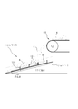
- 1 is a chute and 50 is a conveyor.
- the chute 1 is installed at an angle below the tip of the conveyor 50 that conveys the object to be conveyed.
- the chute 1 is a chute having a known structure having a bottom plate 2 and side plates 3 and 3 rising from both side edges.
- the upper surface of the bottom plate 2 of the chute 1 is a sliding surface 2a.
- the chute 1 of the present embodiment is provided with a staying means 10 for retaining a part of the transported object g falling from the conveyor 50 on the sliding surface 2a.
- the staying means 10 includes a storage part 11 and a sliding part 16.
- the storage section 11 is formed in a lattice shape by combining a plurality of vertical bars 12 extending in the longitudinal direction of the chute 1 and a plurality of horizontal bars 13 extending in the width direction.
- the storage unit 11 is fixed on the bottom plate 14 and joined and integrated by left and right side plates 15 and 15.
- the sliding part 16 is provided in front of the storage part 11. This front means the downstream side in the direction in which the transported object g is sent while rolling.
- the sliding portion 16 is composed of a bottom plate 14 without using a horizontal rail. That is, the transported object g is configured to easily roll or slide forward.
- the bottom plate 14 and the side plate 15 use what extended the thing of the storage part 11 ahead.
- the width and length of the staying means 10 may be appropriately selected according to use conditions.
- the width of the staying means 10 may be the same as the belt width of the conveyor 50 or about 1.2 to 1.3 times in consideration of the meandering of the belt. In this case, even if the transported object g such as a lump falls, it can be sufficiently accommodated.
- the length of the staying means 10 may be determined from the range in which the lump falls.
- the fall range can be determined from the belt speed of the conveyor and the angle ⁇ of the chute.
- the staying means 10 is detachably attached to the bottom plate 2 of the chute 1 via a fixture 17.
- a fixture 17 a known member such as a bolt and a nut using a L-shaped metal fitting in a side view is used without particular limitation.
- a bracket having an appropriate shape may be welded and fixed on the chute 1.
- Bolt connection as well as welding can be fused, so replacement at the time of aging is easy.
- the staying means 10 is an integral part and is detachably attached to the chute 1, it can be removed and attached with less man-hours for maintenance work.
- the size of the cage composed of the vertical rails 12 and the horizontal rails 13 in the storage unit 11 is suitably about 150 mm to 200 mm in height and width and about 50 mm to 70 mm in height depending on the properties of the Ni ore. It is not restricted to the dimension of. If the object to be transported g is other than Ni ore, a material that is smaller or larger than the size of the soot may be appropriately employed.
- the material of the material constituting the staying means 10 is not particularly limited, but the same material as the chute 1 is preferable because it can be easily obtained and processed.
- the plate thickness of the vertical beam 12 or the horizontal beam 13 is not particularly limited, but if it is around 16 mm, it is difficult to cause damage due to collision with a lump, and the internal space of the bag can be sufficiently secured.
- the transported object g is a lump, a granule, a fine powder, or a mixture of these because the four sides of the basket are surrounded.
- it can stay in the cage of the lattice and function as a sacrificial cushioning material.
- a part of the transported object g that has fallen from the conveyor 50 can be stored and held so as not to slide down, so that the stayed material g that has once retained does not change much. For this reason, the function as a sacrificial buffer material can be exhibited reliably over a long period of time.
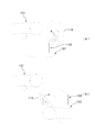
- the chute 1 itself has a bowl shape that is curved in a front view, and accordingly, the staying means 20 is also configured to have a curved lower edge.
- the staying means 20 includes a storage part 21 and a sliding part 26.
- the storage unit 21 is integrated by connecting a plurality of horizontal bars 23 to a bottom plate 24. More specifically, the storage unit 21 is configured by using a plurality of horizontal bars 23 extending in the width direction of the chute 1 and installing the plurality of horizontal bars 23 at intervals in the longitudinal direction of the chute 1. And each horizontal rail 23 is comprised with the board
- the sliding part 26 is comprised by the baseplate 24, and the crosspiece is not used. That is, the conveyed object g is easy to slide and move.
- the four horizontal rails 23 are also fixed to the left and right side plates 25, 25. However, when the height of the horizontal rail 23 is low, a structure in which the horizontal rail 23 is fixed to the bottom plate 24 without using the side plate 25 may be used.
- the staying means 20 has a shape in which the lower edge is curved. However, as described above, this is matched with the curved shape of the chute 1, so that the staying means 20 may be configured to have the same curvature radius. Further, although no vertical rail is used, such a structure can also be used depending on the properties of the conveyed object g. For example, when the lump that is the transported object g is small, the rigidity of the storage unit 21 is sufficient even without a vertical rail. However, it is of course possible to adopt a structure using vertical bars.
- the staying means 20 is detachably attached to the chute 1 via a fitting 27 such as welding or a bolt / nut via an appropriate bracket.
- the horizontal rail 23 exists so as to extend in the width direction of the chute 1, it is possible to store a part of the transported object g that has dropped from the conveyor and to prevent the sliding from occurring. , There is not much replacement of the accumulated material once retained. For this reason, the function as a sacrificial buffer material can be exhibited reliably over a long period of time. Further, since the staying means 20 is an integral part and is detachably attached to the chute 1, it can be removed and attached with less man-hours for maintenance work.
- the shape of the reservoirs 11 and 21 in the staying means 10 and 20 is not limited to the above embodiment.
- An appropriate shape other than a lattice shape or a shelf shape can be adopted according to the shape, properties, hardness, etc. of the conveyed object g. In short, it suffices if a certain amount of the object to be transported g can be retained and function as a sacrificial cushioning material.
- the transported object g dropped from the conveyor stays in the staying means 10, and the staying thing itself functions as a sacrificial cushioning material, so that the chute 1 is less damaged and repaired. Less frequent.
Landscapes
- Engineering & Computer Science (AREA)
- Chemical & Material Sciences (AREA)
- Manufacturing & Machinery (AREA)
- Materials Engineering (AREA)
- Mechanical Engineering (AREA)
- Metallurgy (AREA)
- Organic Chemistry (AREA)
- Chutes (AREA)
- Discharge Of Articles From Conveyors (AREA)
- Manufacture And Refinement Of Metals (AREA)
Abstract
L'invention concerne une glissière qui permet d'obtenir une plus longue durée de vie en améliorant la résistance à l'usure. Une glissière (1), qui est installée au niveau d'une inclinaison vers le bas sur un transporteur (50), qui transporte des objets (g), est pourvue d'un moyen de retenue (10) qui retient une partie des objets (g) qui tombent du transporteur (50) sur la surface de glissement de la glissière (1). Le moyen de retenue (10) présente une section de stockage (13) ayant une forme de treillis par une combinaison d'une pluralité de traverses verticales (12), qui s'étendent dans la direction longitudinale, et d'une pluralité de traverses horizontales (13), qui s'étendent dans le sens de la largeur de la glissière (1). Étant donné que le moyen de retenue (10) est en forme de treillis, une quantité appropriée d'objets (g) qui sont tombés du transporteur (50) peut être stockée et retenue de manière à ne pas glisser, de telle sorte que peu d'objets retenus sont remplacés par d'autres objets. Ainsi, les objets retenus agissent eux-mêmes comme matériau de rembourrage sacrificiel sur une longue période et peuvent empêcher l'apparition de points d'usure/d'endommagement sur la glissière (1), réduisant ainsi la fréquence de réparation.
Priority Applications (1)
| Application Number | Priority Date | Filing Date | Title |
|---|---|---|---|
| PH12016500327A PH12016500327B1 (en) | 2014-08-12 | 2016-02-18 | Chute |
Applications Claiming Priority (2)
| Application Number | Priority Date | Filing Date | Title |
|---|---|---|---|
| JP2014164002A JP5862726B1 (ja) | 2014-08-12 | 2014-08-12 | シュート |
| JP2014-164002 | 2014-08-12 |
Publications (1)
| Publication Number | Publication Date |
|---|---|
| WO2016024428A1 true WO2016024428A1 (fr) | 2016-02-18 |
Family
ID=55304060
Family Applications (1)
| Application Number | Title | Priority Date | Filing Date |
|---|---|---|---|
| PCT/JP2015/064855 Ceased WO2016024428A1 (fr) | 2014-08-12 | 2015-05-25 | Glissière |
Country Status (3)
| Country | Link |
|---|---|
| JP (1) | JP5862726B1 (fr) |
| PH (1) | PH12016500327B1 (fr) |
| WO (1) | WO2016024428A1 (fr) |
Cited By (3)
| Publication number | Priority date | Publication date | Assignee | Title |
|---|---|---|---|---|
| DE102016203002A1 (de) * | 2016-02-25 | 2017-08-31 | Thyssenkrupp Ag | Förderanlage zum Fördern von Fördergut |
| JP2023009802A (ja) * | 2021-07-08 | 2023-01-20 | 三菱重工パワーインダストリー株式会社 | シュートユニットおよびボイラプラント |
| JP7545110B2 (ja) | 2020-10-30 | 2024-09-04 | 住友金属鉱山株式会社 | 原料投入用シュート |
Families Citing this family (1)
| Publication number | Priority date | Publication date | Assignee | Title |
|---|---|---|---|---|
| BR112021007281A2 (pt) | 2018-10-16 | 2021-07-20 | Ossdsign Ab | implantes para preencher orifícios perfurados no osso e métodos para preencher orifícios perfurados no osso |
Citations (4)
| Publication number | Priority date | Publication date | Assignee | Title |
|---|---|---|---|---|
| JPS5926804A (ja) * | 1982-08-03 | 1984-02-13 | Nippon Steel Corp | セルフライニング式シユ−ト |
| JPH0288909U (fr) * | 1988-12-27 | 1990-07-13 | ||
| JPH0380013U (fr) * | 1989-12-01 | 1991-08-15 | ||
| US6684999B1 (en) * | 2003-05-05 | 2004-02-03 | Arch Environmental Equipment, Inc. | Impact liner for granular material |
-
2014
- 2014-08-12 JP JP2014164002A patent/JP5862726B1/ja not_active Expired - Fee Related
-
2015
- 2015-05-25 WO PCT/JP2015/064855 patent/WO2016024428A1/fr not_active Ceased
-
2016
- 2016-02-18 PH PH12016500327A patent/PH12016500327B1/en unknown
Patent Citations (4)
| Publication number | Priority date | Publication date | Assignee | Title |
|---|---|---|---|---|
| JPS5926804A (ja) * | 1982-08-03 | 1984-02-13 | Nippon Steel Corp | セルフライニング式シユ−ト |
| JPH0288909U (fr) * | 1988-12-27 | 1990-07-13 | ||
| JPH0380013U (fr) * | 1989-12-01 | 1991-08-15 | ||
| US6684999B1 (en) * | 2003-05-05 | 2004-02-03 | Arch Environmental Equipment, Inc. | Impact liner for granular material |
Cited By (6)
| Publication number | Priority date | Publication date | Assignee | Title |
|---|---|---|---|---|
| DE102016203002A1 (de) * | 2016-02-25 | 2017-08-31 | Thyssenkrupp Ag | Förderanlage zum Fördern von Fördergut |
| DE102016203002A8 (de) * | 2016-02-25 | 2017-12-21 | Thyssenkrupp Ag | Förderanlage zum Fördern von Fördergut |
| US10427875B2 (en) | 2016-02-25 | 2019-10-01 | Thyssenkrupp Industrial Solutions Ag | Conveyor system for conveying materials to be conveyed |
| JP7545110B2 (ja) | 2020-10-30 | 2024-09-04 | 住友金属鉱山株式会社 | 原料投入用シュート |
| JP2023009802A (ja) * | 2021-07-08 | 2023-01-20 | 三菱重工パワーインダストリー株式会社 | シュートユニットおよびボイラプラント |
| JP7262525B2 (ja) | 2021-07-08 | 2023-04-21 | 三菱重工パワーインダストリー株式会社 | シュートユニットおよびボイラプラント |
Also Published As
| Publication number | Publication date |
|---|---|
| PH12016500327A1 (en) | 2016-05-02 |
| JP5862726B1 (ja) | 2016-02-16 |
| PH12016500327B1 (en) | 2016-05-02 |
| JP2016037391A (ja) | 2016-03-22 |
Similar Documents
| Publication | Publication Date | Title |
|---|---|---|
| JP5862726B1 (ja) | シュート | |
| US7527144B2 (en) | Impact bed for conveyor systems | |
| KR101387605B1 (ko) | 벨트 컨베이어의 낙탄 회수 처리시스템 | |
| US10232801B2 (en) | Wear surface | |
| CN101863379B (zh) | 一种物料转接的方法及转接装置 | |
| JP5410065B2 (ja) | 搬送用構造体 | |
| KR101298758B1 (ko) | 슈트용 라이너 | |
| US20160039608A1 (en) | Ceramic Chute Liner | |
| JP2016040207A (ja) | シュート | |
| US8967359B1 (en) | Flow-retarding chutes and spouts and method for delivering dry bulk free-flowing material to a location | |
| JP6798815B2 (ja) | シュート | |
| JP2015189577A (ja) | 供給装置 | |
| KR20150106072A (ko) | .슈트용 라이너 | |
| UA125319C2 (uk) | Зносостійкі перевантажувальні або розподільні лотки | |
| KR102669616B1 (ko) | 벨트컨베이어용 집진 기구 | |
| CN203877472U (zh) | 皮带机转载点v型缓冲溜槽 | |
| CN202529555U (zh) | 一种用于带式输送机的卸煤装置 | |
| JP2023058061A (ja) | ベルトコンベア搬送ルートの変更方法および変更装置、該変更装置を備えるベルトコンベア | |
| CN218538327U (zh) | 一种烧结矿运输漏斗 | |
| JP6502277B2 (ja) | 搬送物供給構造 | |
| CN201494864U (zh) | 耐磨减振式下矿溜子 | |
| JP2009007154A (ja) | せき板付き傾斜コンベア | |
| JP5401854B2 (ja) | ベルトコンベア乗り継ぎ部に設置するシュート | |
| JP6036532B2 (ja) | 既存のライナーの摩耗防止方法 | |
| KR20160075028A (ko) | 부착물 생성 방지 기구를 구비한 슈트 |
Legal Events
| Date | Code | Title | Description |
|---|---|---|---|
| WWE | Wipo information: entry into national phase |
Ref document number: 12016500327 Country of ref document: PH |
|
| 121 | Ep: the epo has been informed by wipo that ep was designated in this application |
Ref document number: 15832548 Country of ref document: EP Kind code of ref document: A1 |
|
| NENP | Non-entry into the national phase |
Ref country code: DE |
|
| 122 | Ep: pct application non-entry in european phase |
Ref document number: 15832548 Country of ref document: EP Kind code of ref document: A1 |