WO2016024437A1 - 靴紐巻取装置の取付構造 - Google Patents
靴紐巻取装置の取付構造 Download PDFInfo
- Publication number
- WO2016024437A1 WO2016024437A1 PCT/JP2015/067004 JP2015067004W WO2016024437A1 WO 2016024437 A1 WO2016024437 A1 WO 2016024437A1 JP 2015067004 W JP2015067004 W JP 2015067004W WO 2016024437 A1 WO2016024437 A1 WO 2016024437A1
- Authority
- WO
- WIPO (PCT)
- Prior art keywords
- shoelace
- base member
- winding device
- cover
- shoe
- Prior art date
- Legal status (The legal status is an assumption and is not a legal conclusion. Google has not performed a legal analysis and makes no representation as to the accuracy of the status listed.)
- Ceased
Links
Images



Classifications
-
- A—HUMAN NECESSITIES
- A43—FOOTWEAR
- A43C—FASTENINGS OR ATTACHMENTS OF FOOTWEAR; LACES IN GENERAL
- A43C11/00—Other fastenings specially adapted for shoes
- A43C11/16—Fastenings secured by wire, bolts, or the like
- A43C11/165—Fastenings secured by wire, bolts, or the like characterised by a spool, reel or pulley for winding up cables, laces or straps by rotation
-
- A—HUMAN NECESSITIES
- A43—FOOTWEAR
- A43C—FASTENINGS OR ATTACHMENTS OF FOOTWEAR; LACES IN GENERAL
- A43C11/00—Other fastenings specially adapted for shoes
- A43C11/14—Clamp fastenings, e.g. strap fastenings; Clamp-buckle fastenings; Fastenings with toggle levers
-
- A—HUMAN NECESSITIES
- A43—FOOTWEAR
- A43B—CHARACTERISTIC FEATURES OF FOOTWEAR; PARTS OF FOOTWEAR
- A43B23/00—Uppers; Boot legs; Stiffeners; Other single parts of footwear
- A43B23/02—Uppers; Boot legs
-
- A—HUMAN NECESSITIES
- A43—FOOTWEAR
- A43C—FASTENINGS OR ATTACHMENTS OF FOOTWEAR; LACES IN GENERAL
- A43C11/00—Other fastenings specially adapted for shoes
-
- A—HUMAN NECESSITIES
- A43—FOOTWEAR
- A43C—FASTENINGS OR ATTACHMENTS OF FOOTWEAR; LACES IN GENERAL
- A43C11/00—Other fastenings specially adapted for shoes
- A43C11/008—Combined fastenings, e.g. to accelerate undoing or fastening
-
- A—HUMAN NECESSITIES
- A43—FOOTWEAR
- A43C—FASTENINGS OR ATTACHMENTS OF FOOTWEAR; LACES IN GENERAL
- A43C11/00—Other fastenings specially adapted for shoes
- A43C11/20—Fastenings with tightening devices mounted on the tongue
-
- A—HUMAN NECESSITIES
- A43—FOOTWEAR
- A43C—FASTENINGS OR ATTACHMENTS OF FOOTWEAR; LACES IN GENERAL
- A43C7/00—Holding-devices for laces
- A43C7/08—Clamps drawn tight by laces
-
- Y—GENERAL TAGGING OF NEW TECHNOLOGICAL DEVELOPMENTS; GENERAL TAGGING OF CROSS-SECTIONAL TECHNOLOGIES SPANNING OVER SEVERAL SECTIONS OF THE IPC; TECHNICAL SUBJECTS COVERED BY FORMER USPC CROSS-REFERENCE ART COLLECTIONS [XRACs] AND DIGESTS
- Y10—TECHNICAL SUBJECTS COVERED BY FORMER USPC
- Y10T—TECHNICAL SUBJECTS COVERED BY FORMER US CLASSIFICATION
- Y10T24/00—Buckles, buttons, clasps, etc.
- Y10T24/21—Strap tighteners
- Y10T24/2183—Ski, boot, and shoe fasteners
-
- Y—GENERAL TAGGING OF NEW TECHNOLOGICAL DEVELOPMENTS; GENERAL TAGGING OF CROSS-SECTIONAL TECHNOLOGIES SPANNING OVER SEVERAL SECTIONS OF THE IPC; TECHNICAL SUBJECTS COVERED BY FORMER USPC CROSS-REFERENCE ART COLLECTIONS [XRACs] AND DIGESTS
- Y10—TECHNICAL SUBJECTS COVERED BY FORMER USPC
- Y10T—TECHNICAL SUBJECTS COVERED BY FORMER US CLASSIFICATION
- Y10T24/00—Buckles, buttons, clasps, etc.
- Y10T24/37—Drawstring, laced-fastener, or separate essential cooperating device therefor
- Y10T24/3703—Includes separate device for holding drawn portion of lacing
- Y10T24/3724—Includes separate device for holding drawn portion of lacing having lacing wound thereabout or wedged therein
Definitions
- the present invention relates to a shoelace winding device mounting structure.
- a shoelace winding device 300 shown in FIG. 9 has been proposed by the applicant of the present application.
- the shoelace winding device 300 is driven to rotate by an operation handle portion 301, and a reel 302 for taking up a shoelace, and the rotation of the reel 302.
- a base member 304 that is formed of a substantially bottomed cylindrical body that houses the reel 302 and that has an inner peripheral surface formed with an annular gear that includes a plurality of teeth that engage the ratchet claw 303.
- This is a shoelace winding device 300 provided with a shoelace winding system.
- the shoelace winding device 300 is attached to the shoe by directly sewing the flange 305 formed integrally with the lower portion of the base member 304 to the shoe (patent). References 1, 2).
- the shoelace winding device described in Patent Document 4 does not employ the above-described shoelace winding system, but is provided on the teeth provided on the annular ratchet and on the annular reel. A structure that regulates the rotation direction of the reel by teeth is adopted.
- the shoelace winding device described in Patent Literature 5 and Patent Literature 6 includes an annular gear and a ratchet claw, but employs a structure in which a member having a reel storage portion is directly attached to the shoe. Further, the shoelace winding device described in Patent Document 7 does not employ the shoelace winding system as described above, and the rotation direction of the disk-shaped ratchet wheel by the claw provided on the lever arm. Adopts a structure that regulates
- the shoelace winding device mounting structure described in Patent Documents 1 to 3 has the following problems 1) to 5). 1) Since the shoelace winding system is fixed by screwing a metal male screw to the resin shaft provided on the base member on which the annular gear is formed, the male screw is over-tightened or the force applied from the male screw If the female screw of the shaft is crushed, the fixing state between the shaft and the male screw becomes incomplete, and the shoelace winding system may not operate normally, or the shoelace winding system may come off. 2) To repair the shoelace winding device when the annular gear is worn or damaged, it is necessary to remove the base member sewn on the shoe from the shoe and replace it, which sews the shoe skin. This can lead to repairs that are difficult or practically difficult, or require excessive cost and labor.
- the shoelace winding device is fixed to the shoe by fitting the housing of the shoelace winding device into a receiving recess formed in the shoe.
- the housing is firmly fixed, it is difficult to take out the shoelace winding device from the receiving recess, and there is a problem that the repair and replacement are hindered.
- the object of the present invention is to solve all the above-mentioned problems in the conventional shoelace winding device mounting structure, easy to attach the shoelace winding device to the shoe, and the mounting state is strong, And it is providing the attachment structure of the shoelace winding device which can operate
- another object of the present invention is to easily remove the shoelace winding system from the shoe in the event of a malfunction in the shoelace winding device, and to minimize the parts to be replaced. Therefore, it is an object of the present invention to provide a shoelace winding device mounting structure that can be easily maintained.
- the present invention comprises: a reel driven by an operating handle portion for winding a shoelace, a ratchet claw for restricting rotation of the reel, and a substantially bottomed cylindrical body for housing the reel, And a base member formed with an annular gear comprising a plurality of teeth with which the ratchet pawl engages an inner peripheral surface, wherein the base member is directly attached to and detached from the upper outer side.
- a base member mounting cover comprising: a substantially bottomed cylindrical cover portion that can be fixed and held inside; and a flange portion that bulges around the cover portion so as to follow the shape of the shoe
- the structure for attaching the shoelace winding device provided with "is the main feature.
- the cover part or the base member of the present invention preferably includes a lock mechanism that locks the base member in a state of being fixed to the cover part.
- the lock mechanism that locks the base member in a state of being fixed to the cover portion is configured to rotate the base member to restrict the removal of the base member to the outside.
- it may be composed of a rotation-preventing unevenness that engages with each other.
- the unevenness for rotation prevention according to the present invention may be configured to be accessible from the outside of the base member to release the engaged state.
- the cover portion of the present invention includes a shoelace introduction port that opens on a cylindrical inner surface, and a cylindrical shoelace guide portion that extends from the shoelace introduction port along the flange portion includes the shoelace introduction portion. The diameter is reduced in the vicinity of the lace introduction port, and the tip of the shoelace insertion tube inserted into the shoelace guide portion may be introduced to the vicinity of the shoelace introduction port. .
- the flange portion of the present invention may be composed of a plurality of portions that can be independently deformed.
- the lower surface of the cover of the present invention is curved so as to follow the shape of the shoe.
- the shoelace is composed of an operation handle, a ratchet claw, and the like. Not only can the take-up system be easily removed from the base member, but the base member can also be easily removed from the base member mounting cover, and these parts can be easily repaired and replaced.
- the cover part or the base member includes a lock mechanism that locks the base member in a state of fixing the base member to the cover part, the base member and the cover part The fixed state can be reliably maintained, and the base member can be easily detached from the cover portion by releasing the lock.
- the lock mechanism that locks the base member in a state in which the base member is fixed to the cover portion is configured to rotate the base member and restrict the removal of the base member to the outside, and the peripheral surface of the cover portion and the base In order to maintain the engagement of the retaining irregularities formed on the peripheral surface of the member and engaging each other, and formed on the inner bottom surface of the cover part and the lower surface of the base member, By constituting the engaging concave and convex portions to be engaged, the base member can be restricted so that it cannot be easily removed outward by rotating the base member. Moreover, the base member can be removed from the cover portion by releasing the engagement of the unevenness for rotation prevention.
- the concave and convex portions for rotation prevention according to the present invention so that the engaged state can be released by accessing from the outside of the base member, the operation of removing the base member from the cover portion can be easily performed.
- the cover portion of the present invention includes a shoelace introduction port that opens to a cylindrical inner surface, and a cylindrical shoelace guide portion that extends from the shoelace introduction port along the flange portion includes the shoelace introduction portion.
- the diameter of the shoelace is reduced in the vicinity of the mouth, and the tip of the shoelace insertion tube inserted into the shoelace guide portion is introduced to the vicinity of the shoelace introduction opening. Will be guided by the shoelace insertion tube to the vicinity of the shoelace inlet, so that the base member attachment cover or the base member and the shoelace can be prevented from directly rubbing, the shoelace cutting and the base member attachment Damage to the cover and the base member can be prevented.
- the base member can be prevented from being deformed even if the cover part is deformed, The normal operation of the shoelace winding device can be ensured.
- This also makes the base member thin and light.
- the flange portion of the present invention from a plurality of parts that can be deformed independently, not only can the base member mounting cover be easily fitted to the shape of the shoe, but also the cover portion is distorted. This prevents the normal operation of the shoelace winding device from being hindered.
- the lower part of the cover portion of the present invention is curved so as to follow the shape of the shoe, so that the shoelace winding device can be attached to the shoe without harming the feeling of wearing the shoe. it can.
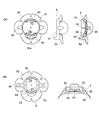
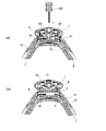
- FIG. 1 is a diagram showing an attachment structure of a shoelace winding device and parts constituting a shoelace winding system embodying the present invention.
- FIG. 1A shows an operation handle portion of the shoelace winding device, The perspective view which shows the state which decomposed
- (B) is a top view of a base member, a side view, and sectional drawing
- (C) is a perspective view of the cover for base member attachment.
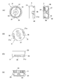
- FIG. 2 is a diagram showing a base member mounting cover that embodies the shoelace winding device mounting structure of the present invention.
- FIG. 2A is a plan view, a side view, and a sectional view of the base member mounting cover.
- FIG. B) is a bottom view and a cross-sectional view of the base member mounting cover.
- 3A and 3B are views showing a base member embodying the attachment structure of the shoelace winding device of the present invention, wherein FIG. 3A is a plan view, a side view and a sectional view, FIG. 3B is a bottom view, and FIG. Is a front view, and (D) is a cross-sectional view.
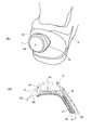
- 4A and 4B show a heel portion of a shoe provided with the shoelace winding device mounting structure of the present invention, FIG. 4A is a perspective view of the heel portion of the shoe, and FIG. 4B explains an internal structure of the heel portion of the shoe.
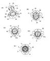
- FIG. 5 is a perspective view showing the manner in which the base member is mounted on the base member mounting cover embodying the present invention in the order of (A) to (D), and the plan view showing the state of the internal ratchet pawl in (E).
- FIG. 6A and 6B are views showing a state in which the base member is mounted on the base member mounting cover embodying the present invention, in which FIG. 6A is a plan view, and FIG. 6B and FIG.
- FIG. 7 is a cross-sectional view showing how a reel is mounted in the shoelace winding device mounting structure embodying the present invention.
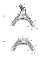
- FIG. 8 is a cross-sectional view showing a state in which a ratchet claw, a handle portion, and the like are mounted by a shoelace winding device mounting structure embodying the present invention, and (A) shows a state in which the shoelace can be tightened.
- (B) is a figure which shows the state which can loosen a shoelace.
- FIG. 9 is a cross-sectional view showing the shoelace winding device mounting structure before the improvement according to the present invention, wherein (A) shows a state in which the shoelace can be tightened, and (B) loosens the shoelace. It is a figure which shows the state which can do.
- the present invention comprises: a reel driven by an operating handle portion for winding a shoelace, a ratchet claw for restricting rotation of the reel, and a substantially bottomed cylindrical body for housing the reel, And a base member formed with an annular gear comprising a plurality of teeth with which the ratchet pawl engages an inner peripheral surface, wherein the base member is directly attached to and detached from the upper outer side.
- a base member mounting cover comprising: a substantially bottomed cylindrical cover portion that can be fixed and held inside; and a flange portion that bulges around the cover portion so as to follow the shape of the shoe.
- the shoelace winding device 1 is configured so that a shoelace 2 made of a metal wire coated with a resin can fasten the upper portion of the shoe S and the periphery of the shoe mouth portion.
- the shoelace winding device 1 includes a base member 3 having an annular gear 34 described below, a reel 4 for winding the shoelace 2, and rotation and stop of the reel 4.
- a stopper member 5 having four ratchet claws 51 for control, an operation handle portion 6 for rotationally driving the reel 4, and the operation handle portion 6 and the stopper member 5 are connected to the base member.
- a shoelace winding system comprising a shaft member 7 that is rotatably fixed to the base member 3 for mounting on the base member 3, and a spring member 8 whose one end is pivotally supported by the shaft member 7. ing.
- the base member 3 is composed of a bottomed cylindrical body 31 formed in a substantially bottomed cylindrical shape as a whole, and includes a reel storage portion 32 for storing the reel 4 therein, and the reel storage portion 32 includes A rotating shaft 33 for pivotally supporting the reel 4 projects from the center of the bottom.
- the base member 3 is formed with an annular gear 34 formed of a plurality of teeth with which the ratchet pawl 51 engages with an upper inner peripheral surface of the bottomed cylindrical body 31.
- This annular gear 34 constitutes a ratchet mechanism in cooperation with an elongated plate-like ratchet pawl 51 formed on the substantially square stopper member 5 and rotates in the clockwise direction in the direction in which the shoelace 2 is wound (FIG. 5E).
- the cross-section is formed in a “sawtooth” shape so that the ratchet pawl 51 can move only in the direction (positive rotation).
- the base member 3 is formed with a shoelace pulling outlet 35 opened at a side portion from the bottom of the reel housing portion 32 at a position 180 degrees apart from each other, and the shoelace 2 wound around the reel 4 is provided. It can be introduced into the reel storage portion 32.
- the base member 3 is attached to the heel portion of the shoe S by a base member mounting cover 9, and the base member mounting cover 9 can be attached and detached directly from the upper outer side.
- a substantially bottomed cylindrical cover portion 91 that can be fixed and held inside, and a flange portion 92 that bulges thinly around the cover portion 91 so as to follow the shape of the shoe.
- the shoelace winding device 1 can be firmly fixed to the shoe S by the thin plate-like flange portion 92 being sewn and fixed to the shoe S.
- a gap of about 0.5 to 1.0 mm is formed between the outer peripheral surface of the base member 3 and the inner peripheral surface of the cover portion 91, and the cover portion 91 is deformed. Does not reach the base member 3 directly. Therefore, even if the cover 91 and the base member 3 are thin and light, not only can the shoelace winding device 1 be stably operated, but also the shoelace winding device 1 attached to the shoe S is rugged. A sense of incongruity can be eliminated.
- the back surface of the cover part 91 and the back surface of the flange part 92 are curved and formed so as to follow the shape of the heel part of the shoe S so as to be substantially along the spherical surface.
- the height of the cover portion 91 is set to be approximately the same as the thickness of the reel 4, that is, a height that covers about half of the lower side of the base member 3.
- the flange portion 92 is formed so as to be entirely divided into petals by slits 92a, and each petal-like portion has a plurality of independently deformable structures. Thereby, it is easy to carry out the attachment by deforming so as to match the shape of each part of the shoe S to which the base member attachment cover 9 is attached, and also corresponding to the deformation of the shoe S during use. The shape is easy to follow, and the uncomfortable feeling caused by wearing the shoelace winding device 1 can be reduced. Further, the petal-like portions of the flange portion 92 are independently deformed, so that an effect of preventing the cover portion 91 from being deformed when the shoe S is deformed can be obtained.
- the cover portion 91 and the base member 3 include a lock mechanism that locks the base member 3 in a state of being fixed to the cover portion 91.
- This locking mechanism has a configuration described in the following (i) and (ii) as unevenness for retaining and a configuration described in the following (iii) and (iv) as unevenness for preventing rotation. It is configured.
- (I) In order to restrict the removal of the base member 3 outward by rotating the base member 3, a retaining protrusion 93 formed to protrude along the inner peripheral surface of the cover portion 91. .
- the retaining protrusions 93 are formed in parallel with the inner bottom surface of the cover portion 91 and are formed at positions 180 degrees apart from each other.
- the protrusion 93 for preventing removal is formed on the outer peripheral surface of the base member 3.
- a concave groove 36 for retaining Each of the recess-preventing concave grooves 36 is parallel to the lower surface (outer bottom surface or back surface) of the base member 3 and is formed at a position 180 degrees apart from each other. Then, the retaining rib 93 engaged with the retaining groove 36 abuts on the end of the retaining groove 36 (the left end shown in FIG. 3C), Further rotation of the base member 3 in the counterclockwise direction is stopped (the state shown in FIG. 6A is referred to as “stop position”).
- the bottomed cylindrical body 31 constituting the base member 3 formed in a substantially bottomed cylindrical shape has a lower outer peripheral surface portion from the right end of the retaining groove 36 to the shoelace pulling outlet 35.
- the diameter of 31a is reduced so as to obtain a space in which the above-mentioned retaining protrusion 93 can be inserted.
- a leaf spring-like protrusion 94 for rotation prevention formed on the inner bottom surface of the cover portion 91 in order to maintain the engagement state of the protrusions and depressions at the “stop position”.
- Each of the rotation stop projections 94 is formed at positions 180 degrees apart from each other on the inner bottom surface of the cover portion 91, and obliquely so that the tip side gradually rises upward and projects. Is formed.
- the direction in which the rotation-stopping projection 94 is formed obliquely is 180 degrees opposite.
- (Iv) In order to maintain the engagement state of the unevenness for retaining the retainer, it is formed on the lower surface (outer bottom surface) of the base member 3 and is engaged with the protrusion 94 for preventing rotation at the “stop position”.
- Each rotation-preventing through-hole 37 is formed at a position 180 degrees apart from each other on the inner bottom surface of the base member 3, and the rotation-preventing projection 94 is fitted and fitted. It is formed diagonally so that it gradually becomes deep.
- the base member 3 can be removed from the reel housing portion 32 side. 3 is accessed from the outside, and the two anti-rotation projections 94 are simultaneously pressed and rotated in a direction to remove the base member 3.
- the operation for simultaneously pressing the rotation-stopping projection 94 is set so that a metal fitting (not shown) having two projections separated from each other used when the spike rod is attached and detached can be used. It is.
- the base member 3 is urged counterclockwise when the shoelace 2 is tightened, that is, urged in a direction to stop at the “stop position”.
- the base member 3 is not rotated in the direction in which it is removed. Further, in this “stop position”, the shoelace pulling outlet 35 of the base member 3 always faces and aligns with the shoelace inlet 95 formed in the cover portion 91.
- the cover portion 91 of the base member mounting cover 9 has a total of two shoelace inlets 95 that are open to the cylindrical inner surface of the cover portion 91 between the two protrusions 93 for retaining. I have one. Furthermore, the inner surface of the cylindrical shoelace guide portion 96 extending along the flange portion 92 from the shoelace introduction port 95 is reduced in the vicinity of the shoelace introduction port 95. Then, the tip of the shoelace insertion tube T inserted into the shoelace guide portion 96 is introduced to the vicinity of the shoelace introduction port 95 so that the tip of the shoelace insertion tube T does not enter further. It has become.
- the reel 4 includes a bearing portion 41 at the center thereof, and the rotation shaft 33 of the base member 3 is inserted into the inner surface side of the bearing portion 41, and the reel 4 is placed inside the reel storage portion 32. It can be rotated.
- a plurality of fins 42 are formed on the upper side of the reel 4, and meshing with the fins 52 formed on the lower side of the stopper member 5 allows rotation of the operation handle portion 6 to the reel 4. It can communicate.
- the stopper member 5 has an engaging claw portion 53 projecting from its four corners engaged with an engagement hole 61 formed through the operation handle portion 6 so that the stopper member 5 is located on the inner side (lower side) of the operation handle portion 6. ) And is integrated with the operation handle portion 6, and is interposed between the reel 4 and the operation handle portion 6 to rotate the operation handle portion 6 to the reel 4. A locked state where transmission is possible and a release state where the reel 4 is separated from the operation handle 6 so that the reel 4 can freely rotate can be realized.
- the shaft member 7 is fixed to the base member 3 with a screw 7a in order to rotatably mount the integrated operation handle portion 6 and the stopper member 5 to the base member 3. Then, the integrated operation handle 6 and the stopper member 5 are moved closer to the base member 3 (see FIG. 8A), and the release position separated from the base member 3 (FIG. 8 ( B) can be held and guided in a movable state.
- the shaft member 7 is formed in a quadrangular prism shape, and the spring member is formed with respect to the bearing portion 71 formed by notching two opposing side portions of the shaft member 7 in a direction orthogonal to the axial center direction. By inserting the linear one end portion (shaft portion 81) formed in 8, the spring member 8 is rotatably supported.
- the spring member 8 is curved and formed in a substantially U shape as a whole, and a spring portion 82 on the other end side of the curved portion is an engaging portion provided on the inner surface of the integrated operation handle portion 6 and the stopper member 5. 62 abuts.
- the locking portion 62 with which the other end portion (spring portion 82) of the spring member 8 abuts is the narrowest outer end portion of the spring accommodating space formed in a wedge shape at the boundary portion between the operation handle portion 6 and the stopper member 5. Is provided. Further, a disc-like cap 10 is fitted on the upper side of the operation handle portion 6 so that dust or the like does not enter the shoelace winding device 1.
- a through hole 11 is formed in the central portion of the cap 10, and the screw 7 a on the inner side (lower side) of the cap 10 is operated by the tool 100 through the through hole 11 and operated from the base member 3.
- the handle portion 6, the shaft member 7, and the reel 4 can be removed.
- a wire rope obtained by twisting 49 strands made of stainless steel having a diameter of 0.11 to 0.13 mm, processed with a swaging machine, and coated with nylon resin is preferably used. be able to.
- a method of assembling each part of the shoelace winding device 1 described above and attaching it to the shoe S will be described.
- a plurality of shoelace guides (not shown) are attached to the back of the shoe S, and are arranged in the front-rear direction so as to embed a shoelace insertion tube T on both sides of the shoe mouth.
- the rear end portion of the shoelace insertion tube T is disposed so as to reach the heel portion of the shoe S including the lining 12, the counter 13, and the like.
- a non-woven tube cover 14 is placed inside the shoelace insertion tube T, and a cushion material 15 made of EVA is arranged outside the shoelace insertion tube T.
- the base member mounting cover 9 is temporarily fixed to the heel portion of the shoe S with an adhesive.
- the rear end portion of the shoelace insertion tube T is formed in the vicinity of the shoelace introduction port 95 of the tubular (or tunnel-shaped) shoelace guide portion 96 extending along the flange portion 92. Inserted to the reduced diameter part. Accordingly, it is possible to prevent the shoelace 2 from rubbing directly against the base member attachment cover 9 or the base member 3 in the vicinity of the shoelace introduction port 95, and the durability of the base member attachment cover 9 and the base member 3 can be prevented. Can be improved.
- the base member attaching cover 9 can be firmly fixed to the heel portion of the shoe S by sewing the flange portion 92 of the base member attaching cover 9 with a thread from the outer skin 16 of the shoe S. .
- FIGS. 5A to 5D show a state in which the lower outer peripheral surface portion 31a of the base member 3 is made to correspond to the protrusion 93 for retaining
- FIG. 5 (D) shows the base member 3. Is rotated counterclockwise, and the locking protrusions 93 are brought into contact with the ends of the locking grooves 36 to prevent locking (see FIG. 6).
- the concaves and convexes constituting the locking mechanism are formed at positions that are point-symmetric with respect to the centers of the cover 91 and the base member 3, so that when the base member 3 is attached to the cover 91. Even if the direction of the base member 3 is 180 degrees different, the shoelace pulling outlet 35 of the base member 3 is always aligned and locked so as to face the shoelace introduction port 95 of the cover portion 91. It is like that.
- the shoelace outlet 35 of the base member 3 ⁇ the shoelace inlet 95 of the base member attachment cover 9 ⁇ the shoelace guide portion 96 ⁇ the shoelace insertion tube T ⁇ the plurality of shoelaces so as to face the upper portion of the shoe S
- Individually fixed shoelace guides (not shown) ⁇ Shoelace insertion tube T ⁇ Shoelace guide portion 96 of the base member mounting cover 9 ⁇ Shoelace introduction port 95 ⁇ Shoelace outlet 35 of the base member 3 in this order.
- the shoelace 2 is inserted.
- the shoelace 2 is arranged so as to sew the upper part of the shoe S, and the both ends of the shoe S from the heel part of the shoe S as shown in FIG. Pulled out.
- both ends of the shoelace 2 are fixed to the reel 4, and the reel 4 is placed in the reel storage portion 32 of the base member 3.
- the stopper member 5 is integrated with the operation handle portion 6, and the shaft member 7 and the spring member are added thereto. 8 is assembled.
- the spring member 8 includes a substantially square shaft hole 63 formed at the center of the handle portion 6 for operation and a substantially square shaft hole 54 formed at the center of the stopper member 5.
- the spring portion 82 of the spring member 8 is inserted into the spring storage space from the expanded portion of the operating handle portion 6 with the shaft hole 63 expanded, and the spring portion 82 is further inserted into the spring storage space. It is guided to rotate from the inner end side to the outer end narrowest portion side and is assembled to the operation handle portion 6. Since the flange 72 formed at the upper end of the shaft member 7 abuts on a locking step 64 formed at the edge of the shaft hole 63 of the operation handle 6, the operation handle 6 is separated from the shaft member 7. It will not come off.
- the screw 7 a is inserted into the screw insertion hole 73 of the shaft member 7, and the shaft member 7 and the like are attached to the base member 3. Installing.
- the shoelace winding device 1 can be assembled by fitting the cap 10 into the operation handle portion 6. Since the through hole 11 is formed in the center of the cap 10, the cap 10 is first fitted into the operation handle 6 and then the screw 7 a is operated to attach the shaft member 7 and the like to the base member 3. You can also When disassembling the shoelace winding device 1 for maintenance or repair, the tool 100 is inserted from the through-hole 11 of the cap 10 and the screw 7a is removed, so that the assembled stopper member 5 and operation handle portion are removed. 6. The shaft member 7 and the spring member 8 can be removed from the base member 3 together.
- a method of using the shoelace winding device 1 configured as described above will be described.
- the operation handle portion 6 is moved clockwise in the locked position where the operation handle portion 6 of the shoelace winding device 1 is brought close to the base member 3.
- the shoelace 2 is wound around the reel 4 by rotating.
- the reel 4 does not rotate in the direction in which the shoelace 2 is loosened by the ratchet pawl 51 of the stopper member 5 coming into contact with the annular gear 34.
- the “operation handle portion” is not particularly limited as long as it functions as an operation portion for rotationally driving the reel 4, and has a polygonal shape. May be.
- the present invention is not limited to the shoelace winding device 1 mainly for tightening the upper portion of the shoe S.
- the shoe S differs in that only the periphery of the shoe mouth of the shoe S is tightened.
- the present invention may be embodied in the mounting structure of the shoelace winding device 1 for tightening the portion.
- the position where the shoelace winding device 1 is attached is not limited to the heel portion of the shoe S, but is used when the shoelace winding device 1 is attached to the back or side (near the ankle) of the shoe S.
- the present invention may be embodied in the mounting structure of the shoelace winding device 1.
- the retaining member formed on the inner peripheral surface of the cover portion 91 and the outer peripheral surface of the base member 3 is engaged with each other.
- the unevenness for use instead of the unevenness formed in the direction horizontal to the bottom surface of the cover portion 91 and the base member 3, a spiral shape on the inner peripheral surface of the cover portion 91 and the outer peripheral surface of the base member 3, or You may implement using the unevenness
- the present invention is not only capable of providing a shoe having a shoelace winding device that is small and lightweight, has excellent operability and comfort, is resistant to failure, and has excellent operational stability and durability, as well as assembly workability and maintenance. Suitable for use as an attachment structure for a shoelace winding device that can be easily used for a wide variety of shoes, such as sports shoes, women's shoes, and children's shoes. Is possible.
Landscapes
- Footwear And Its Accessory, Manufacturing Method And Apparatuses (AREA)
Abstract
Description
この靴紐巻取装置300の取付構造においては、前記ベース部材304の下部に一体成形したフランジ305を靴に直接縫い付けることで、靴紐巻取装置300を靴に取り付けるようにしている(特許文献1、2)。
この靴紐巻取装置においても、環状ギヤを形成したベース部材に一体成形したフランジを設け、そのフランジを靴に直接縫い付けることで、靴紐巻取装置を靴に取り付けている。
そして、本発明は、特に上記のような靴紐巻取システムを有する靴紐巻取装置の取付構造を改良した靴紐巻取装置の取付構造に関するものである。
さらに、特許文献7に記載されている靴紐巻取装置は、上記のような靴紐巻取システムを採用しているものではなく、レバーアームに設けた爪によって円盤状のラチェット車輪の回転方向を規制する構造を採用している。
1)環状ギヤを形成したベース部材に設けた樹脂製の軸に金属製の雄ネジを螺合して靴紐巻取システムを固定しているため、雄ネジの締めすぎや、雄ネジから加わる力によって軸の雌ネジが潰れてしまうと、軸と雄ネジとの固定状態が不完全となり、靴紐巻取システムが正常に作動しなくなったり、靴紐巻取システムが外れてしまう恐れがある。
2)環状ギヤが摩耗したり損傷した場合に、靴紐巻取装置を修理するには、靴に縫い付けられたベース部材を靴から外して交換する必要があり、これは靴の外皮を縫い直すことに繋がり、事実上困難であるか、又は過大な費用と手間がかかる作業が必要となる。
3)環状ギヤを形成したベース部材に靴から変形応力が加わると、環状ギヤが変形し、靴紐が緩んでしまったり、靴紐巻取装置が正常に作動しなくなる恐れがある。
このような障害を防ぐために、環状ギヤを形成したベース部材の剛性を高めることが行われるが、すると、ベース部材が大型化したり、重くなってしまい、靴の履き心地が悪くなるという問題も生じる。
4)靴紐巻取装置を取り付ける部分の靴の形状とベース部材の形状が一致していないと、履き心地が良くなかったり、靴に損傷が生じたりすることがある。
5)靴紐がベース部材と擦れ合って、靴紐が切れたり、ベース部材が損傷する恐れがある。
さらに、本発明の他の目的は、万が一、靴紐巻取装置に不具合が生じた場合、靴紐巻取システムを靴から簡単に取り外すことができ、また、交換対象部品を最小限にすることができ、メンテナンス作業の容易な靴紐巻取装置の取付構造を提供することにある。
そして、前記ベース部材を前記カバー部に固定した状態でロックする前記ロック機構は、当該ベース部材を回動させてベース部材の外方への取り外しを規制するために、前記カバー部の周面及び前記ベース部材の周面に形成され互いに係合する抜け止め用の凹凸と、当該抜け止め用の凹凸の係合状態を維持するために、前記カバー部の内底面及び前記ベース部材の下面に形成され互いに係合する回転止め用の凹凸と、から構成されているものであってもよい。
また、本発明の前記カバー部は、円筒状の内面に開口する靴紐導入口を備えており、当該靴紐導入口から前記フランジ部に沿って延びる筒状の靴紐ガイド部が、前記靴紐導入口付近において縮径されており、当該靴紐ガイド部内に挿入される靴紐挿通用のチューブの先端が前記靴紐導入口付近まで導入されるようになっているものであってもよい。
本発明の前記フランジ部は、独立して変形可能な複数の部分から構成されているものであってもよい。
また、本発明の前記カバー部は、靴の形状に沿うように下面が湾曲形成されていることが好ましい。
前記ベース部材を前記カバー部に固定した状態でロックする前記ロック機構を、当該ベース部材を回動させてベース部材の外方への取り外しを規制するために、前記カバー部の周面及び前記ベース部材の周面に形成され互いに係合する抜け止め用の凹凸と、当該抜け止め用の凹凸の係合状態を維持するために、前記カバー部の内底面及び前記ベース部材の下面に形成され互いに係合する回転止め用の凹凸と、から構成することにより、ベース部材を回動操作することで簡単にベース部材を外方へ取り外しできなくなるように規制することができる。
また、回転止め用の凹凸の係合を解除することで、ベース部材をカバー部から取り外すことができるようになる。
本発明の前記フランジ部を、独立して変形可能な複数の部分から構成することにより、靴の形状に合わせてベース部材取付用カバーを装着し易くすることができるばかりか、カバー部が歪むことによって靴紐巻取装置の正常な動作が妨げられることを防止することができる。
また、本発明の前記カバー部を、靴の形状に沿うように下面が湾曲形成されているものとすることで、靴の装着感を害することなく、靴紐巻取装置を靴に取り付けることができる。
この靴紐巻取装置1は、樹脂被覆された金属製のワイヤーからなる靴紐2によって靴Sの甲部及び履き口部周囲を締め付けることができるようになっている。
そして、前記ベース部材3は、前記有底円筒体31の上部内周面に前記ラチェット爪51が係合する複数の歯からなる環状ギヤ34が形成されている。
そして、薄板状のフランジ部92が前記靴Sに縫い付け固定されることで靴紐巻取装置1を靴Sに対して強固に固定することができるものである。
従って、カバー部91やベース部材3を薄く軽いものとしても、靴紐巻取装置1を安定して動作させることができるばかりか、靴Sに靴紐巻取装置1を装着した場合におけるゴツゴツした違和感を解消することもできる。
なお、前記カバー部91の裏面及び前記フランジ部92の裏面は、靴Sのかかと部分の形状に沿うように、ほぼ球面に沿うように湾曲形成されている。
また、本実施例において、前記カバー部91の高さは、前記リール4の厚さと同程度、即ち、前記ベース部材3の下側を約半分程度覆う高さに設定してある。
これにより、ベース部材取付用カバー9が取り付けられている靴Sの各部の形状に合致するように変形して取り付けを行い易いばかりか、靴Sが使用の際に変形することにも対応して形状が追従し易く、靴紐巻取装置1を装着したことによる違和感を低減できる。
また、前記フランジ部92の花弁状の各部分が独立して変形することで、靴Sが変形した際にカバー部91まで変形してしまうことを防止する効果を得ることができる。
このロック機構は、抜け止め用の凹凸としての下記(i)及び(ii)に記載されている構成と、回転止め用の凹凸としての下記(iii)及び(iv)に記載されている構成から構成されている。
(i)前記ベース部材3を回動させることでベース部材3の外方への取り外しを規制するために、前記カバー部91の内周面に沿って突出形成された抜け止め用の突条93。
この抜け止め用の突条93は、前記カバー部91の内底面と平行状であって、互いに180度離間した位置にて各1個形成されている。
(ii)前記ベース部材3を回動させることでベース部材3の外方への取り外しを規制するために、前記ベース部材3の外周面に形成され前記抜け止め用の突条93が係合する抜け止め用の凹溝36。
この抜け止め用の凹溝36は、前記ベース部材3の下面(外底面又は裏面)と平行状であって、互いに180度離間した位置にて各1個形成されている。
そして、前記抜け止め用の凹溝36に係合した前記抜け止め用の突条93は、抜け止め用の凹溝36の末端(図3(C)に示す左側の端部)に当接し、前記ベース部材3のそれ以上の反時計回り方向への回動を止めるようになっている(図6(A)に示す状態であって、「停止位置」という。)。
また、略有底円筒状に形成された前記ベース部材3を構成する有底円筒体31は、前記抜け止め用の凹溝36の右側の端部から前記靴紐引出口35までの下部外周面部31aが、前記抜け止め用の突条93を差し込むことができるスペースを得られるように縮径されている。
(iii)前記「停止位置」における前記抜け止め用の凹凸の係合状態を維持するために、前記カバー部91の内底面に形成された板バネ状の回転止め用の突起94。
この回転止め用の突起94は、前記カバー部91の内底面において互いに180度離間した位置にて各1個形成されており、かつ、先端側が上方に向かって徐々に起き上がって突出するように斜めに形成されている。
また、前記回転止め用の突起94が斜めに形成されている向きは、180度反対方向となっている。
(iv)前記抜け止め用の凹凸の係合状態を維持するために、前記ベース部材3の下面(外底面)に形成され、前記「停止位置」において前記回転止め用の突起94と係合する回転止め用の透孔37。
この回転止め用の透孔37は、前記ベース部材3の内底面において互いに180度離間した位置にて各1個形成されており、かつ、前記回転止め用の突起94がフィットして嵌まり込むように徐々に深くなるように斜めに形成されている。
このように前記「停止位置」において、前記回転止め用の透孔37に嵌まり込んだ回転止め用の突起94を外すには、前記ベース部材3のリール収納部32側から、即ち、ベース部材3の外方からアクセスして、前記2個の回転止め用の突起94を同時に押さえ、前記ベース部材3を外す方向へ回せばよい。
本実施例において、この回転止め用の突起94を同時に押さえる操作は、スパイク鋲を着脱する際に使用する互いに離間した2個の突起を有する金具(図示しない)を用いることができるように設定してある。
また、この「停止位置」において、前記ベース部材3の前記靴紐引出口35は、常に前記カバー部91に形成された靴紐導入口95と向き合って整合するようになっている。
さらに、前記靴紐導入口95から前記フランジ部92に沿って延びる筒状の靴紐ガイド部96は、前記靴紐導入口95付近において内面が縮径されている。そして、当該靴紐ガイド部96内に挿入される靴紐挿通用のチューブTの先端が前記靴紐導入口95付近まで導入され、靴紐挿通用のチューブTの先端がそれ以上入り込まないようになっている。
前記リール4の上側には、複数のフィン42が形成されており、前記ストッパー部材5の下側に形成されたフィン52と噛合することで、前記操作用ハンドル部6の回転を前記リール4に伝達できるようになっている。
また、前記操作用ハンドル部6の上側には、円盤状のキャップ10が嵌合して靴紐巻取装置1の内部にゴミなどが入り込まないようになっている。
まず、靴Sの甲部に複数個の靴紐ガイド(図示しない)を取り付け、靴Sの履き口部の両サイドに靴紐挿通用のチューブTを埋め込むように前後方向に配置する。その靴紐挿通用のチューブTの後端部は、ライニング12、カウンター13などからなる靴Sのかかと部分まで届くように配置する。また、前記靴紐挿通用のチューブTの内側には不織布製チューブカバー14が置かれ、前記靴紐挿通用のチューブTの外側にはEVAからなるクッション材15が配置される。
従って、前記靴紐導入口95の付近において、前記靴紐2がベース部材取付用カバー9又はベース部材3と直接擦れ合うことを防止することができ、ベース部材取付用カバー9及びベース部材3の耐久性を向上させることができる。
なお、図5(B)及び(C)は、前記抜け止め用の突条93に、ベース部材3の下部外周面部31aを対応させている様子を示し、図5(D)は、ベース部材3を反時計回り方向に回動して、前記抜け止め用の突条93を抜け止め用の凹溝36の末端に当接させ、ロックを成立させた様子を示す(図6参照)。
これにより、靴紐2は、靴Sの甲部を縫い合わせるように配置され、靴Sの履き口部の両サイドを経て、図7(A)に示すように靴Sのかかと部分から両端部が引き出される。
次に、靴紐2の両端部をリール4に固定し、そのリール4をベース部材3のリール収納部32内に入れる。
この場合、前記バネ部材8は、前記軸部材7が前記操作用ハンドル部6の中心に形成された略四角形状の軸穴63とストッパー部材5の中心に形成された略四角形状の軸穴54に挿入されるのであるが、当該バネ部材8のバネ部82が操作用ハンドル部6の軸穴63を拡げた拡張部から前記バネ収納空間に挿入され、さらに当該バネ部82がバネ収納空間の内端側から外端最狭部側へ回動するように案内されて前記操作用ハンドル部6に組み付けられる。
なお、前記軸部材7の上端部に形成したフランジ72が前記操作用ハンドル部6の軸穴63の縁に形成した係止段部64に当接するため、操作用ハンドル部6が軸部材7から外れることはない。
なお、キャップ10の中央部には透孔11が形成されているため、先にキャップ10を操作用ハンドル部6に嵌め込んでからネジ7aを操作して軸部材7などをベース部材3に装着することもできる。
メンテナンス又は修理のために靴紐巻取装置1を分解する際には、キャップ10の透孔11から工具100を挿入し、ネジ7aを外すことで、組み付けられたストッパー部材5、操作用ハンドル部6、軸部材7及びバネ部材8をベース部材3からまとめて取り外すことができる。
ベース部材3・・・ナイロン、又は、ポリカーボネート
ベース部材取付用カバー9・・・ナイロン
リール4、ストッパー部材5、軸部材7・・・POM(ポリアセタール)
操作用ハンドル部6・・・ナイロンとその周囲にTPE(熱可塑性エラストマー)
バネ部材8・・・ステンレス鋼
ネジ7a・・・炭素鋼
キャップ10・・・ABS樹脂
靴Sを履いた後に、靴紐2を締め付けるには、靴紐巻取装置1の操作用ハンドル部6を前記ベース部材3に接近させたロック位置にて操作用ハンドル部6を時計回り方向に回転操作し、靴紐2をリール4に巻き付ける。
この場合、ストッパー部材5のラチェット爪51が環状ギヤ34に当接することで、靴紐2が緩む方向にリール4が回転することはない。
この時、バネ部材8は圧縮され、当該バネ部材8が最も圧縮される反転位置を越えることにより、操作用ハンドル部6をベース部材3から離した解除位置に移動させる(図8(B)に示す状態)。
上記のように前記操作用ハンドル部6がロック位置から解除位置に移動すると、リール4のフィン42とストッパー部材5のフィン52との噛合が解除され、リール4が自由に回転できるようになり、靴紐2が緩められる。
2 靴紐
3 ベース部材
31 有底円筒体
31a 下部外周面部
32 リール収納部
33 回転軸
34 環状ギヤ
35 靴紐引出口
36 抜け止め用の凹溝
37 回転止め用の透孔
4 リール
41 軸受部
42 フィン
5 ストッパー部材
51 ラチェット爪
52 フィン
53 取付用爪部
54 軸穴
6 操作用ハンドル部
61 係合穴
62 係止部
63 軸穴
64 係止段部
7 軸部材
71 軸受部
72 フランジ
73 ネジ挿入孔
7a ネジ
8 バネ部材
81 軸部(一端部)
82 バネ部(他端部)
9 ベース部材取付用カバー
91 カバー部
92 フランジ部
92a スリット
93 抜け止め用の突条
94 回転止め用の突起
95 靴紐導入口
96 靴紐ガイド部
10 キャップ
11 透孔
12 ライニング
13 カウンター
14 不織布製チューブカバー
15 EVAからなるクッション材
16 外皮
100 工具
300 靴紐巻取装置
301 操作用ハンドル部
302 リール
303 ラチェット爪
304 ベース部材
305 フランジ
S 靴
T 靴紐挿通用のチューブ
Claims (8)
- 操作用ハンドル部にて回転駆動され、靴紐を巻き取るためのリールと、
前記リールの回転を規制するラチェット爪と、
前記リールを収納する略有底円筒体からなり、その内周面に前記ラチェット爪が係合する複数の歯からなる環状ギヤを形成したベース部材と、
を備えた靴紐巻取装置の取付構造であって、
前記ベース部材を直接上部外方から着脱可能に固定して内部に保持することができる略有底円筒状のカバー部と、
靴の形状に沿うように前記カバー部の周囲に膨出したフランジ部と、
を備えたベース部材取付用カバーを設けたことを特徴とする靴紐巻取装置の取付構造。 - 前記カバー部又は前記ベース部材は、前記ベース部材をカバー部に固定した状態でロックするロック機構を備えていることを特徴とする請求項1に記載の靴紐巻取装置の取付構造。
- 前記ベース部材を前記カバー部に固定した状態でロックする前記ロック機構は、
当該ベース部材を回動させてベース部材の外方への取り外しを規制するために、前記カバー部の周面及び前記ベース部材の周面に形成され互いに係合する抜け止め用の凹凸と、
当該抜け止め用の凹凸の係合状態を維持するために、前記カバー部の内底面及び前記ベース部材の下面に形成され互いに係合する回転止め用の凹凸と、
から構成されていることを特徴とする請求項2に記載の靴紐巻取装置の取付構造。 - 前記回転止め用の凹凸は、ベース部材の外方からアクセスして係合状態を解除可能に構成されていることを特徴とする請求項3に記載の靴紐巻取装置の取付構造。
- 前記カバー部は、円筒状の内面に開口する靴紐導入口を備えており、
当該靴紐導入口から前記フランジ部に沿って延びる筒状の靴紐ガイド部が、前記靴紐導入口付近において縮径されており、
当該靴紐ガイド部内に挿入される靴紐挿通用のチューブの先端が前記靴紐導入口付近まで導入されるようになっていることを特徴とする請求項2に記載の靴紐巻取装置の取付構造。 - 前記ベース部材の外周面と前記カバー部の内周面との間には隙間が有り、前記カバー部が変形しても前記ベース部材が変形しないようになっていることを特徴とする請求項2に記載の靴紐巻取装置の取付構造。
- 前記フランジ部は、独立して変形可能な複数の部分から構成されていることを特徴とする請求項2に記載の靴紐巻取装置の取付構造。
- 前記カバー部は、靴の形状に沿うように下面が湾曲形成されていることを特徴とする請求項2に記載の靴紐巻取装置の取付構造。
Priority Applications (5)
| Application Number | Priority Date | Filing Date | Title |
|---|---|---|---|
| KR1020177003345A KR20170042577A (ko) | 2014-08-11 | 2015-06-12 | 신발끈 권취 장치의 부착 구조 |
| US15/502,391 US10258109B2 (en) | 2014-08-11 | 2015-06-12 | Structure for attaching shoelace winding apparatus |
| EP15831265.2A EP3181003B1 (en) | 2014-08-11 | 2015-06-12 | Shoelace winding apparatus |
| HK17105204.2A HK1231337B (zh) | 2014-08-11 | 2015-06-12 | 鞋带卷取装置 |
| CN201580041415.6A CN106572723B (zh) | 2014-08-11 | 2015-06-12 | 鞋带卷取装置 |
Applications Claiming Priority (2)
| Application Number | Priority Date | Filing Date | Title |
|---|---|---|---|
| JP2014-163867 | 2014-08-11 | ||
| JP2014163867A JP6406919B2 (ja) | 2014-08-11 | 2014-08-11 | 靴紐巻取装置の取付構造 |
Publications (1)
| Publication Number | Publication Date |
|---|---|
| WO2016024437A1 true WO2016024437A1 (ja) | 2016-02-18 |
Family
ID=55304068
Family Applications (1)
| Application Number | Title | Priority Date | Filing Date |
|---|---|---|---|
| PCT/JP2015/067004 Ceased WO2016024437A1 (ja) | 2014-08-11 | 2015-06-12 | 靴紐巻取装置の取付構造 |
Country Status (6)
| Country | Link |
|---|---|
| US (1) | US10258109B2 (ja) |
| EP (1) | EP3181003B1 (ja) |
| JP (1) | JP6406919B2 (ja) |
| KR (1) | KR20170042577A (ja) |
| CN (1) | CN106572723B (ja) |
| WO (1) | WO2016024437A1 (ja) |
Cited By (3)
| Publication number | Priority date | Publication date | Assignee | Title |
|---|---|---|---|---|
| CN107157018A (zh) * | 2017-06-28 | 2017-09-15 | 义乌威思得进出口有限公司 | 一种鞋带收紧扣 |
| CN109310182A (zh) * | 2016-03-15 | 2019-02-05 | 耐克创新有限合伙公司 | 用于自动化鞋类平台的箱式系带通道 |
| WO2026076256A1 (en) * | 2024-10-02 | 2026-04-09 | Boa Technology, Inc. | Reel based closure system |
Families Citing this family (18)
| Publication number | Priority date | Publication date | Assignee | Title |
|---|---|---|---|---|
| KR102566159B1 (ko) * | 2010-04-30 | 2023-08-16 | 보아 테크놀러지, 인크. | 릴 기반 끈 조임 시스템 |
| EP3182941B1 (en) * | 2015-02-27 | 2018-03-14 | F.G.P. S.R.L. | Manually operated rotative locking device for orthopedic orthoses or braces |
| JP6882827B2 (ja) | 2016-08-10 | 2021-06-02 | 株式会社アルペン | 巻取装置 |
| JP6881993B2 (ja) | 2017-02-01 | 2021-06-02 | 株式会社アルペン | 紐巻取装置を備えた物品 |
| WO2018155732A1 (ko) * | 2017-02-22 | 2018-08-30 | 김석환 | 끈조절장치 |
| KR101833680B1 (ko) * | 2017-08-04 | 2018-02-28 | 김정곤 | 신발끈의 조임장치 |
| EP4098141B1 (en) * | 2017-11-08 | 2024-02-14 | NIKE Innovate C.V. | Articles of footwear with wrap around closure system and/or foot wrapping securing straps |
| CN111115388B (zh) | 2018-10-30 | 2021-11-19 | 陈金柱 | 紧固装置 |
| US11311997B2 (en) * | 2019-03-07 | 2022-04-26 | Ossur Iceland Ehf | Adapter for a rotary device |
| CN111972776B (zh) * | 2020-08-28 | 2021-12-10 | 吉林大学 | 一种仿生缓震鞋中底 |
| US11974637B2 (en) * | 2021-03-01 | 2024-05-07 | Ariat International, Inc. | Boots with fit adjustment systems |
| CN115137124B (zh) * | 2021-03-31 | 2024-04-12 | 陈金柱 | 紧固装置及紧固装置安装方法 |
| KR20240000369U (ko) | 2021-08-06 | 2024-02-27 | 롱싱 리우 | 끈 조임 장치 |
| US12108843B2 (en) * | 2021-08-18 | 2024-10-08 | Chin-Chu Chen | Fastening device |
| TWM623553U (zh) * | 2021-08-18 | 2022-02-21 | 陳金柱 | 緊固裝置 |
| IT202100032117A1 (it) * | 2021-12-22 | 2023-06-22 | Alpinestars Res Spa | Calzatura sportiva |
| CN116509108A (zh) | 2022-01-21 | 2023-08-01 | 深圳市爱康伟达智能医疗科技有限公司 | 一种新型的系带装置及其止逆机构 |
| CN115744503B (zh) * | 2022-11-21 | 2025-11-28 | 河源市大邦科枝有限公司 | 一种正反转松紧系绳装置 |
Citations (6)
| Publication number | Priority date | Publication date | Assignee | Title |
|---|---|---|---|---|
| US20080172848A1 (en) * | 2007-01-18 | 2008-07-24 | Chin-Chu Chen | Shoelace fastening assembly |
| JP2009504210A (ja) * | 2005-08-11 | 2009-02-05 | ヘッド・ジャーマニー・ゲーエムベーハー | 靴用回転ファスナ |
| US20100139057A1 (en) * | 2008-11-21 | 2010-06-10 | Soderberg Mark S | Reel based lacing system |
| JP2011514175A (ja) * | 2008-01-18 | 2011-05-06 | ボア テクノロジー,インコーポレイテッド | 閉塞システム |
| JP2013525007A (ja) * | 2010-04-30 | 2013-06-20 | ボア テクノロジー,インコーポレイテッド | リールを基にした紐締めシステム |
| WO2013138759A1 (en) * | 2012-03-15 | 2013-09-19 | Boa Technology Inc. | Tightening mechanisms and applications including the same |
Family Cites Families (15)
| Publication number | Priority date | Publication date | Assignee | Title |
|---|---|---|---|---|
| DE3926514A1 (de) | 1989-08-10 | 1991-02-14 | Weinmann & Co Kg | Drehverschluss fuer einen sportschuh, insbesondere einen skischuh |
| US5157813A (en) | 1991-10-31 | 1992-10-27 | William Carroll | Shoelace tensioning device |
| JPH07208A (ja) | 1991-12-20 | 1995-01-06 | Kobatsuku:Kk | 靴紐締付具 |
| JPH0773525A (ja) | 1993-09-03 | 1995-03-17 | Shin Etsu Chem Co Ltd | 光磁気記録媒体およびその薄膜製造装置 |
| KR100598627B1 (ko) * | 2005-06-27 | 2006-07-13 | 주식회사 신경 | 신발끈 조임기 |
| KR101028468B1 (ko) * | 2009-04-06 | 2011-04-15 | 주식회사 신경 | 신발끈 조임장치 |
| CN201718602U (zh) * | 2010-05-11 | 2011-01-26 | 胡荣富 | 鞋卷线器 |
| KR101053551B1 (ko) * | 2010-11-04 | 2011-08-03 | 주식회사 신경 | 신발끈 조임장치 |
| US9101181B2 (en) * | 2011-10-13 | 2015-08-11 | Boa Technology Inc. | Reel-based lacing system |
| US10076160B2 (en) * | 2013-06-05 | 2018-09-18 | Boa Technology Inc. | Integrated closure device components and methods |
| JP6087219B2 (ja) | 2013-06-18 | 2017-03-01 | 株式会社ジャパーナ | 靴紐巻取装置 |
| JP6105404B2 (ja) | 2013-06-18 | 2017-03-29 | 株式会社ジャパーナ | 靴紐巻取用リール |
| CN203492894U (zh) * | 2013-09-11 | 2014-03-26 | 陈金柱 | 带体收放装置 |
| KR102297325B1 (ko) | 2013-09-13 | 2021-09-03 | 보아 테크놀러지, 인크. | 릴 기반 폐쇄 장치 및 그에 따른 방법 |
| KR102822775B1 (ko) * | 2016-12-09 | 2025-06-20 | 보아 테크놀러지, 인크. | 릴 기반의 폐쇄 시스템 |
-
2014
- 2014-08-11 JP JP2014163867A patent/JP6406919B2/ja active Active
-
2015
- 2015-06-12 WO PCT/JP2015/067004 patent/WO2016024437A1/ja not_active Ceased
- 2015-06-12 US US15/502,391 patent/US10258109B2/en active Active
- 2015-06-12 CN CN201580041415.6A patent/CN106572723B/zh active Active
- 2015-06-12 KR KR1020177003345A patent/KR20170042577A/ko not_active Withdrawn
- 2015-06-12 EP EP15831265.2A patent/EP3181003B1/en active Active
Patent Citations (6)
| Publication number | Priority date | Publication date | Assignee | Title |
|---|---|---|---|---|
| JP2009504210A (ja) * | 2005-08-11 | 2009-02-05 | ヘッド・ジャーマニー・ゲーエムベーハー | 靴用回転ファスナ |
| US20080172848A1 (en) * | 2007-01-18 | 2008-07-24 | Chin-Chu Chen | Shoelace fastening assembly |
| JP2011514175A (ja) * | 2008-01-18 | 2011-05-06 | ボア テクノロジー,インコーポレイテッド | 閉塞システム |
| US20100139057A1 (en) * | 2008-11-21 | 2010-06-10 | Soderberg Mark S | Reel based lacing system |
| JP2013525007A (ja) * | 2010-04-30 | 2013-06-20 | ボア テクノロジー,インコーポレイテッド | リールを基にした紐締めシステム |
| WO2013138759A1 (en) * | 2012-03-15 | 2013-09-19 | Boa Technology Inc. | Tightening mechanisms and applications including the same |
Cited By (7)
| Publication number | Priority date | Publication date | Assignee | Title |
|---|---|---|---|---|
| CN109310182A (zh) * | 2016-03-15 | 2019-02-05 | 耐克创新有限合伙公司 | 用于自动化鞋类平台的箱式系带通道 |
| CN109310182B (zh) * | 2016-03-15 | 2022-08-09 | 耐克创新有限合伙公司 | 用于自动化鞋类平台的箱式系带通道 |
| CN115624230A (zh) * | 2016-03-15 | 2023-01-20 | 耐克创新有限合伙公司 | 用于自动化鞋类平台的箱式系带通道 |
| US11707116B2 (en) | 2016-03-15 | 2023-07-25 | Nike, Inc. | Box lacing channel for automated footwear platform |
| US12075889B2 (en) | 2016-03-15 | 2024-09-03 | Nike, Inc. | Box lacing channel for automated footwear platform |
| CN107157018A (zh) * | 2017-06-28 | 2017-09-15 | 义乌威思得进出口有限公司 | 一种鞋带收紧扣 |
| WO2026076256A1 (en) * | 2024-10-02 | 2026-04-09 | Boa Technology, Inc. | Reel based closure system |
Also Published As
| Publication number | Publication date |
|---|---|
| US10258109B2 (en) | 2019-04-16 |
| US20170224056A1 (en) | 2017-08-10 |
| EP3181003A1 (en) | 2017-06-21 |
| JP2016036679A (ja) | 2016-03-22 |
| EP3181003B1 (en) | 2019-08-07 |
| JP6406919B2 (ja) | 2018-10-17 |
| CN106572723B (zh) | 2019-01-11 |
| EP3181003A4 (en) | 2018-04-11 |
| HK1231337A1 (zh) | 2017-12-22 |
| KR20170042577A (ko) | 2017-04-19 |
| CN106572723A (zh) | 2017-04-19 |
Similar Documents
| Publication | Publication Date | Title |
|---|---|---|
| JP6406919B2 (ja) | 靴紐巻取装置の取付構造 | |
| EP3498124B1 (en) | Winding device | |
| JP6087219B2 (ja) | 靴紐巻取装置 | |
| JP6105404B2 (ja) | 靴紐巻取用リール | |
| JP7581287B2 (ja) | 締結装置 | |
| KR101837194B1 (ko) | 줄 길이 조절장치 | |
| KR101833680B1 (ko) | 신발끈의 조임장치 | |
| JP2020185411A (ja) | 紐締めシステムに使用されるリール | |
| US20100251524A1 (en) | String securing device | |
| KR20210049884A (ko) | 체결 디바이스 | |
| EP2508094B1 (en) | Loop for shoelace utilizing asymmetric pulley | |
| KR102143929B1 (ko) | 끈 조임장치 | |
| JP6960316B2 (ja) | オイルパンのドレンプラグ構造 | |
| AU2019463869B2 (en) | Screen wire regulation and control device with easy disassembly and assembly structure | |
| HK1231337B (zh) | 鞋带卷取装置 | |
| WO2018143060A1 (ja) | 巻取装置 | |
| WO2013039015A1 (ja) | 留め具 | |
| WO2017068937A1 (ja) | 巻取装置 | |
| CN220308553U (zh) | 系带松紧装置 | |
| HK40007058B (zh) | 卷取装置 |
Legal Events
| Date | Code | Title | Description |
|---|---|---|---|
| 121 | Ep: the epo has been informed by wipo that ep was designated in this application |
Ref document number: 15831265 Country of ref document: EP Kind code of ref document: A1 |
|
| ENP | Entry into the national phase |
Ref document number: 20177003345 Country of ref document: KR Kind code of ref document: A |
|
| NENP | Non-entry into the national phase |
Ref country code: DE |
|
| REEP | Request for entry into the european phase |
Ref document number: 2015831265 Country of ref document: EP |
|
| WWE | Wipo information: entry into national phase |
Ref document number: 2015831265 Country of ref document: EP |