WO2016027570A1 - 送電装置およびその製造方法、並びに、受電装置およびその製造方法 - Google Patents
送電装置およびその製造方法、並びに、受電装置およびその製造方法 Download PDFInfo
- Publication number
- WO2016027570A1 WO2016027570A1 PCT/JP2015/068955 JP2015068955W WO2016027570A1 WO 2016027570 A1 WO2016027570 A1 WO 2016027570A1 JP 2015068955 W JP2015068955 W JP 2015068955W WO 2016027570 A1 WO2016027570 A1 WO 2016027570A1
- Authority
- WO
- WIPO (PCT)
- Prior art keywords
- wall
- power transmission
- housing
- coil unit
- power
- Prior art date
- Legal status (The legal status is an assumption and is not a legal conclusion. Google has not performed a legal analysis and makes no representation as to the accuracy of the status listed.)
- Ceased
Links
Images





Classifications
-
- B—PERFORMING OPERATIONS; TRANSPORTING
- B60—VEHICLES IN GENERAL
- B60L—PROPULSION OF ELECTRICALLY-PROPELLED VEHICLES; SUPPLYING ELECTRIC POWER FOR AUXILIARY EQUIPMENT OF ELECTRICALLY-PROPELLED VEHICLES; ELECTRODYNAMIC BRAKE SYSTEMS FOR VEHICLES IN GENERAL; MAGNETIC SUSPENSION OR LEVITATION FOR VEHICLES; MONITORING OPERATING VARIABLES OF ELECTRICALLY-PROPELLED VEHICLES; ELECTRIC SAFETY DEVICES FOR ELECTRICALLY-PROPELLED VEHICLES
- B60L50/00—Electric propulsion with power supplied within the vehicle
- B60L50/50—Electric propulsion with power supplied within the vehicle using propulsion power supplied by batteries or fuel cells
- B60L50/60—Electric propulsion with power supplied within the vehicle using propulsion power supplied by batteries or fuel cells using power supplied by batteries
-
- B—PERFORMING OPERATIONS; TRANSPORTING
- B60—VEHICLES IN GENERAL
- B60L—PROPULSION OF ELECTRICALLY-PROPELLED VEHICLES; SUPPLYING ELECTRIC POWER FOR AUXILIARY EQUIPMENT OF ELECTRICALLY-PROPELLED VEHICLES; ELECTRODYNAMIC BRAKE SYSTEMS FOR VEHICLES IN GENERAL; MAGNETIC SUSPENSION OR LEVITATION FOR VEHICLES; MONITORING OPERATING VARIABLES OF ELECTRICALLY-PROPELLED VEHICLES; ELECTRIC SAFETY DEVICES FOR ELECTRICALLY-PROPELLED VEHICLES
- B60L53/00—Methods of charging batteries, specially adapted for electric vehicles; Charging stations or on-board charging equipment therefor; Exchange of energy storage elements in electric vehicles
- B60L53/10—Methods of charging batteries, specially adapted for electric vehicles; Charging stations or on-board charging equipment therefor; Exchange of energy storage elements in electric vehicles characterised by the energy transfer between the charging station and the vehicle
- B60L53/12—Inductive energy transfer
- B60L53/122—Circuits or methods for driving the primary coil, e.g. supplying electric power to the coil
-
- H—ELECTRICITY
- H01—ELECTRIC ELEMENTS
- H01F—MAGNETS; INDUCTANCES; TRANSFORMERS; SELECTION OF MATERIALS FOR THEIR MAGNETIC PROPERTIES
- H01F27/00—Details of transformers or inductances, in general
- H01F27/02—Casings
-
- H—ELECTRICITY
- H01—ELECTRIC ELEMENTS
- H01F—MAGNETS; INDUCTANCES; TRANSFORMERS; SELECTION OF MATERIALS FOR THEIR MAGNETIC PROPERTIES
- H01F27/00—Details of transformers or inductances, in general
- H01F27/02—Casings
- H01F27/04—Leading of conductors or axles through casings, e.g. for tap-changing arrangements
-
- H—ELECTRICITY
- H01—ELECTRIC ELEMENTS
- H01F—MAGNETS; INDUCTANCES; TRANSFORMERS; SELECTION OF MATERIALS FOR THEIR MAGNETIC PROPERTIES
- H01F27/00—Details of transformers or inductances, in general
- H01F27/24—Magnetic cores
-
- H—ELECTRICITY
- H01—ELECTRIC ELEMENTS
- H01F—MAGNETS; INDUCTANCES; TRANSFORMERS; SELECTION OF MATERIALS FOR THEIR MAGNETIC PROPERTIES
- H01F27/00—Details of transformers or inductances, in general
- H01F27/28—Coils; Windings; Conductive connections
- H01F27/2804—Printed windings
-
- H—ELECTRICITY
- H01—ELECTRIC ELEMENTS
- H01F—MAGNETS; INDUCTANCES; TRANSFORMERS; SELECTION OF MATERIALS FOR THEIR MAGNETIC PROPERTIES
- H01F27/00—Details of transformers or inductances, in general
- H01F27/34—Special means for preventing or reducing unwanted electric or magnetic effects, e.g. no-load losses, reactive currents, harmonics, oscillations, leakage fields
- H01F27/36—Electric or magnetic shields or screens
- H01F27/363—Electric or magnetic shields or screens made of electrically conductive material
-
- H—ELECTRICITY
- H01—ELECTRIC ELEMENTS
- H01F—MAGNETS; INDUCTANCES; TRANSFORMERS; SELECTION OF MATERIALS FOR THEIR MAGNETIC PROPERTIES
- H01F38/00—Adaptations of transformers or inductances for specific applications or functions
- H01F38/14—Inductive couplings
-
- H—ELECTRICITY
- H02—GENERATION; CONVERSION OR DISTRIBUTION OF ELECTRIC POWER
- H02J—ELECTRIC POWER NETWORKS; CIRCUIT ARRANGEMENTS OR SYSTEMS FOR SUPPLYING OR DISTRIBUTING ELECTRIC POWER; SYSTEMS FOR STORING ELECTRIC ENERGY
- H02J50/00—Circuit arrangements or systems for wireless supply or distribution of electric power
- H02J50/10—Circuit arrangements or systems for wireless supply or distribution of electric power using inductive coupling
- H02J50/12—Circuit arrangements or systems for wireless supply or distribution of electric power using inductive coupling of the resonant type
-
- B—PERFORMING OPERATIONS; TRANSPORTING
- B60—VEHICLES IN GENERAL
- B60L—PROPULSION OF ELECTRICALLY-PROPELLED VEHICLES; SUPPLYING ELECTRIC POWER FOR AUXILIARY EQUIPMENT OF ELECTRICALLY-PROPELLED VEHICLES; ELECTRODYNAMIC BRAKE SYSTEMS FOR VEHICLES IN GENERAL; MAGNETIC SUSPENSION OR LEVITATION FOR VEHICLES; MONITORING OPERATING VARIABLES OF ELECTRICALLY-PROPELLED VEHICLES; ELECTRIC SAFETY DEVICES FOR ELECTRICALLY-PROPELLED VEHICLES
- B60L5/00—Current collectors for power supply lines of electrically-propelled vehicles
-
- B—PERFORMING OPERATIONS; TRANSPORTING
- B60—VEHICLES IN GENERAL
- B60M—POWER SUPPLY LINES, AND DEVICES ALONG RAILS, FOR ELECTRICALLY- PROPELLED VEHICLES
- B60M7/00—Power lines or rails specially adapted for electrically-propelled vehicles of special types, e.g. suspension tramway, ropeway, underground railway
-
- Y—GENERAL TAGGING OF NEW TECHNOLOGICAL DEVELOPMENTS; GENERAL TAGGING OF CROSS-SECTIONAL TECHNOLOGIES SPANNING OVER SEVERAL SECTIONS OF THE IPC; TECHNICAL SUBJECTS COVERED BY FORMER USPC CROSS-REFERENCE ART COLLECTIONS [XRACs] AND DIGESTS
- Y02—TECHNOLOGIES OR APPLICATIONS FOR MITIGATION OR ADAPTATION AGAINST CLIMATE CHANGE
- Y02T—CLIMATE CHANGE MITIGATION TECHNOLOGIES RELATED TO TRANSPORTATION
- Y02T10/00—Road transport of goods or passengers
- Y02T10/60—Other road transportation technologies with climate change mitigation effect
- Y02T10/70—Energy storage systems for electromobility, e.g. batteries
-
- Y—GENERAL TAGGING OF NEW TECHNOLOGICAL DEVELOPMENTS; GENERAL TAGGING OF CROSS-SECTIONAL TECHNOLOGIES SPANNING OVER SEVERAL SECTIONS OF THE IPC; TECHNICAL SUBJECTS COVERED BY FORMER USPC CROSS-REFERENCE ART COLLECTIONS [XRACs] AND DIGESTS
- Y02—TECHNOLOGIES OR APPLICATIONS FOR MITIGATION OR ADAPTATION AGAINST CLIMATE CHANGE
- Y02T—CLIMATE CHANGE MITIGATION TECHNOLOGIES RELATED TO TRANSPORTATION
- Y02T10/00—Road transport of goods or passengers
- Y02T10/60—Other road transportation technologies with climate change mitigation effect
- Y02T10/7072—Electromobility specific charging systems or methods for batteries, ultracapacitors, supercapacitors or double-layer capacitors
-
- Y—GENERAL TAGGING OF NEW TECHNOLOGICAL DEVELOPMENTS; GENERAL TAGGING OF CROSS-SECTIONAL TECHNOLOGIES SPANNING OVER SEVERAL SECTIONS OF THE IPC; TECHNICAL SUBJECTS COVERED BY FORMER USPC CROSS-REFERENCE ART COLLECTIONS [XRACs] AND DIGESTS
- Y02—TECHNOLOGIES OR APPLICATIONS FOR MITIGATION OR ADAPTATION AGAINST CLIMATE CHANGE
- Y02T—CLIMATE CHANGE MITIGATION TECHNOLOGIES RELATED TO TRANSPORTATION
- Y02T90/00—Enabling technologies or technologies with a potential or indirect contribution to GHG emissions mitigation
- Y02T90/10—Technologies relating to charging of electric vehicles
- Y02T90/14—Plug-in electric vehicles
Definitions
- the present invention relates to a power transmission device that transmits power to a power receiving device in a contactless manner and a manufacturing method thereof, and a power receiving device that receives power from a power transmission device in a contactless manner and a manufacturing method thereof.
- Patent Documents 1 to 5 a power transmission device that transmits and receives power without contact and a power transmission system that uses the power reception device are known.
- Patent Document 6 relates to a non-contact charger that performs non-contact or wireless charging by transferring electric power by electromagnetic induction to a battery housed in a battery-driven device such as a mobile phone, a smartphone, or a tablet.
- a coil and a circuit board are accommodated in the case.
- Patent Document 7 discloses a housing case in which a coil and a capacitor are housed in a housing case, a mounting surface is made of metal, and a power transmission surface and a periphery thereof are made of resin.
- the shield is only formed in a flat plate shape, and the region in which the coil is accommodated and the region in which the circuit board is accommodated are not partitioned in the exterior case.
- the electromagnetic field generated in the coil reaches the electric device in the outer case, and the electric device may be affected by the electromagnetic field during power transmission.
- noise from the electric device leaks to the outside and affects the external electric device.
- the devices described in the above patent documents there is no mention of a specific manufacturing method.
- An object of the present invention is to provide a power transmission device and a method for manufacturing the power transmission device, a power receiving device and a method for manufacturing the power transmission device, which are capable of reducing the influence on the electric device due to the noise and the leakage of noise from the electric device to the outside.
- This power transmission device is a power transmission device that transmits power to a power receiving device in a contactless manner, and houses a power transmission coil unit, an electrical device connected to the power transmission coil unit, the power transmission coil unit, and the electrical device.
- a housing A housing.
- the housing includes an installation wall located on the installation surface side, an outer shell wall that is provided so as to cover the installation wall from the side surface and forms a space in the housing, a partition wall that partitions the space, A lid portion that closes an opening formed on the power transmission surface of the outer shell wall and allows power transmission by the power transmission coil unit, and the partition wall defines the space of the housing as the lid portion. Is positioned so as to be partitioned into a coil unit housing portion in which the power transmission coil unit is housed and an electrical device housing portion in which the electrical device is housed, and the outer shell wall and the partition wall are It is made of metal.
- the power transmission coil unit and the electric device are in a state of being partitioned by the partition wall formed of metal.
- the electromagnetic field generated in the power transmission coil unit during power transmission is blocked from reaching the electrical device by the partition wall.
- leakage of noise from the electric equipment to the outside can be reduced.
- this power transmission device manufacturing method a step of housing an electric device inside the main housing, a step of closing the electric device of the main housing in which the electric device is housed with a lid, A step of disposing the power transmission coil unit inside the partition wall; and a step of closing the opening of the partition wall with a lid.
- the power receiving device is a power receiving device that transmits power in a non-contact manner from the power transmitting device, and houses the power receiving coil unit, the electric device connected to the power receiving coil unit, the power receiving coil unit, and the electric device.
- a housing a power receiving device that transmits power in a non-contact manner from the power transmitting device, and houses the power receiving coil unit, the electric device connected to the power receiving coil unit, the power receiving coil unit, and the electric device.
- the housing includes an installation wall located on the installation surface side, an outer shell wall that is provided so as to cover the installation wall from the side surface and forms a space in the housing, a partition wall that partitions the space, A lid portion that closes an opening formed in the power receiving surface of the outer shell wall and allows power reception by the power receiving coil unit, and the partition wall defines the space of the housing as the lid portion.
- the power receiving coil unit and the electric device are partitioned by the partition wall formed by the electromagnetic shielding member.
- the electromagnetic field generated in the power receiving coil unit is blocked from reaching the electric device by the partition wall.
- leakage of noise from the electric equipment to the outside can be reduced.
- this power receiving device manufacturing method a step of housing an electric device inside the main housing, a step of closing the electric device of the main housing in which the electric device is housed with a lid, A step of disposing the power receiving coil unit inside the partition wall; and a step of closing the opening of the partition wall with a lid.
- This power receiving device manufacturing method makes it possible to manufacture a power receiving device having a configuration in which a coil and an electric device are integrated in a simple process.
- the coil and the electric device connected to the coil are housed in one housing and the coil and the electric device are integrated, the influence of the electromagnetic field on the electric device during power transmission is reduced. Further, it is possible to provide a power transmission device and a method for manufacturing the power transmission device, and a power reception device and a method for manufacturing the power transmission device that can reduce the leakage of noise from the electric equipment to the outside.
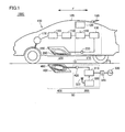
- FIG. 1 is a diagram illustrating a power transmission system in a first embodiment. It is a perspective view which shows the structure of the power transmission apparatus with which the spiral coil in Embodiment 1 was employ
- FIG. 3 is a diagram illustrating various device arrangements of electric devices in the first embodiment. 3 is a diagram illustrating a cross-sectional structure of a power transmission device in Embodiment 1.
- FIG. FIG. 6 is a diagram illustrating a cross-sectional structure of a power transmission device in a second embodiment. FIG. 6 is a first exploded cross-sectional view showing a method for manufacturing a power transmission device in a second embodiment.
- FIG. 10 is a second exploded cross-sectional view showing the method for manufacturing the power transmission device in the second embodiment.
- FIG. 9 is a perspective view illustrating a configuration of a power receiving device in which a spiral coil is employed in a third embodiment.
- FIG. 10 is a perspective view illustrating a configuration of a power receiving device that employs a wound coil according to a third embodiment.
- 10 is a diagram illustrating a cross-sectional structure of a power receiving device in Embodiment 3.
- FIG. 10 is a diagram illustrating a cross-sectional structure of a power receiving device in Embodiment 4.
- FIG. 10 is a first exploded cross-sectional view illustrating a method for manufacturing a power receiving device in a fourth embodiment.
- FIG. 10 is a second exploded cross-sectional view illustrating the method for manufacturing the power receiving device in the fourth embodiment.
- the configuration of the power transmission device installed on the facility side (parking lot or the like) shown below can also be applied to a power reception device placed on the vehicle side.
- the placement surface means the facility (ground) side
- the surface side means the power reception device (vehicle) side.
- the placement surface means the vehicle side
- the surface side means the power transmission device (ground) side.
- the direction indicated by the arrow F in the figure indicates the forward direction and the reverse direction of the vehicle
- the direction indicated by the arrow W in the figure indicates the width direction of the vehicle.
- the power transmission system 1000 includes a power receiving device 10 mounted on the electric vehicle 100 and a power transmission device 50 installed on the facility side such as a parking lot.
- Electric vehicle 100 includes a power receiving device 10 and a vehicle main body 105.
- the power receiving device 10 includes a power receiving coil unit 200 and an electric device 110 provided between the power receiving coil unit 200 and a battery 150 as a power storage device that stores power received by the power receiving coil unit 200.
- the power receiving coil unit 200 includes a power receiving coil 250 and a flat ferrite plate 260.
- the power receiving coil 250 may be either a spiral coil (see FIG. 8) or a wound coil (see FIG. 9).
- FIG. 1 illustrates a spiral power receiving coil 250.
- the electric device 110 includes a capacitor 120, a rectifier 130, a DC / DC converter 140, and the like. In the figure, the power receiving coil 250 and the capacitor 120 are connected in series, but they may be connected in parallel.
- the vehicle body 105 includes a battery 150 connected to the DC / DC converter 140 of the electric device 110, a power control unit 160, a motor unit 170, a communication unit 180, and the like.
- the number of turns of the power receiving coil 250 indicates a distance between the power receiving coil 250 and a power transmitting coil 450 described later, a Q value (for example, Q ⁇ 100) indicating a resonance strength between the power receiving coil 250 and the power transmitting coil 450, and a degree of coupling thereof.
- the coupling coefficient ⁇ is appropriately set so as to increase.
- the power receiving coil 250 is connected to the rectifier 130.
- the rectifier 130 converts the alternating current supplied from the power receiving coil unit 200 into a direct current and supplies it to the DC / DC converter 140.
- the power transmission device 50 includes a power transmission coil unit 400 and an electric device 300.
- the power transmission coil unit 400 includes a power transmission coil 450 and a flat ferrite plate 460.
- the power transmission coil 450 may be either a spiral coil (see FIG. 2) or a wound coil (see FIG. 3).
- FIG. 1 illustrates a spiral power transmission coil 450.
- the electric device 300 includes a capacitor 420, a high frequency power device 310, a power transmission ECU 320, and a communication unit 322.
- the external AC power source 330 is detachably connected using an outlet plug 340 or the like. In the figure, the power transmission coil 450 and the capacitor 420 are connected in series, but they may be connected in parallel.
- the high frequency power device 310 converts power received from the AC power source 330 into high frequency power and supplies the converted high frequency power to the power transmission coil 450.
- the power transmission coil 450 transmits power to the power receiving coil 250 of the power receiving coil unit 200 in a non-contact manner by electromagnetic induction.
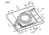
- FIG. 2 is a perspective view illustrating a configuration of a power transmission device 50 in which a spiral coil is employed as the power transmission coil.
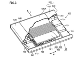
- FIG. 3 is a perspective view illustrating a configuration of the power transmission device 50 in which a spiral coil is employed as the power transmission coil.
- 4 is a diagram showing various device arrangements of the electric device 300, and
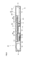
- FIG. 5 is a cross-sectional view taken along line VV in FIG.
- the power transmission device 50 includes the power transmission coil unit 400 that transmits power to the power reception device 10 in a non-contact manner as described above, and the electric device 300 that supplies power to the power transmission coil unit 400 and is connected to an external power source.
- the power transmission coil unit 400 and the electric device 300 are accommodated in a housing 600. Therefore, power transmission device 50 in the present embodiment has a configuration in which power transmission coil unit 400 and electric device 300 are integrated.
- electrical device 300 includes high-frequency power device 310, power transmission ECU 320, and communication unit 322, and these devices are configured.
- the switching power supply 701 constitutes an AC / DC equipment section
- the filter inductors 716 and 720 and the filter capacitors 717 and 721 constitute a filter equipment section
- the DC / RF section 706 constitutes a DC / RF equipment section. To do. These devices are placed on an installation wall 610 that forms the bottom surface of the housing 600.
- the power transmission coil 450 is a planar spiral coil formed so as to surround the winding center line CL, and a hole 450a is formed at the center.
- the power transmission coil 450 is arranged such that the winding center line CL passes through the lid 620A and the installation wall 610. In the example shown in FIG. 5, they are arranged so as to extend in the vertical direction.
- the housing 600 has a flat box shape as a whole, and includes an installation surface S1 disposed on the ground side and a power transmission surface S2 disposed on the power receiving device 10 side.
- the housing 600 is provided so as to cover the installation wall 610 located on the installation surface S1 side, the installation wall 610, and defines an outer shell wall 601 that forms a space in the housing 600 and a space in the housing 600.
- Partition wall 660 is provided so as to cover the installation wall 610 located on the installation surface S1 side, the installation wall 610, and defines an outer shell wall 601 that forms a space in the housing 600 and a space in the housing 600.
- the outer shell wall 601 includes a main surface wall 620 provided on the power transmission surface S2 side, and a side wall 630 positioned on the side surface S3, with an opening 601a formed in the power transmission surface S2.
- the side wall 630 is located between the installation wall 610 and the main surface wall 620.
- the partition wall 660 partitions the inside of the housing 600 into a coil unit housing portion 510 in which the power transmission coil unit 400 provided on the power transmission surface S2 side is housed and an electric device housing portion 520 in which the electric device 300 is housed.
- the coil unit housing 510 has a lid 620A that closes the opening 601a.
- the lid 620A is made of a resin that transmits an electromagnetic field. Thereby, electric power can be transmitted from the power transmission coil unit 400 housed in the coil unit housing portion 510 to the power receiving coil unit 200.
- the outer shell wall 601 is made of metal. Specifically, the main surface wall 620, the side wall 630, and the installation wall 610 are integrally molded metal, and an aluminum member is used as an example in the present embodiment. By forming the outer shell wall 601 from metal, it is possible to suppress noise from the electric device 300 housed in the electric device housing portion 520 from leaking to the outside from the outer shell wall 601.
- the installation wall 610 is generally installed on the ground, the noise of the electric device 300 is suppressed from leaking to the outside from the installation wall 610 side.
- the installation wall 610 is also formed of metal, and noise leakage from the installation wall 610 is also suppressed.
- the entire surface of the main surface wall 620 and the entire surface of the side wall 630 are made of metal.
- a part of the main surface wall 620 is made of a porous plastic that is waterproof and breathable. You may make it form in.
- the outer shell wall is made of metal
- a part of the outer shell wall 601 is made of breathable plastic to ensure breathability, or for internal observation. This includes cases where a part of the outer shell wall 601 is formed of glass or transparent resin, and is not limited to the case where the entire surface of the outer shell wall 601 is formed of metal.
- the side wall 630 is a side surface located in the width direction (W) of the vehicle, but the side wall 640 (see FIGS. 2 and 3) located in the forward / reverse direction of the vehicle is different from the installation wall 610 and the like.
- An aluminum member having a structure is used.
- the partition wall 660 includes a bottom wall 661 located on the installation wall 610 side, and side walls 662 standing from both ends of the bottom wall 661 toward the lid 620A. Since the partition wall 660 needs to prevent the influence of the electromagnetic field on the electric device 300 accommodated in the same casing 600, the partition wall 660 is formed of an electromagnetic field shield member. Although a metal material is mainly used for the electromagnetic shielding member, copper is used in the present embodiment.
- a coil unit housing portion 510 in which the power transmission coil unit 400 is housed and an electric device housing portion 520 in which the electric device 300 is housed are partitioned by a partition wall 660 formed of metal. It is possible to reduce the influence on the electric device 300 due to the electromagnetic field during power transmission. For example, the temperature rise of the electric device 300 due to the generation of eddy currents in the electric device 300 due to the electromagnetic field during power transmission can be prevented.
- power transmission coil 450 is arranged so that winding center line CL passes through lid portion 620A and installation wall 610, a large amount of magnetic flux from power transmission coil 450 flows downward of power transmission coil 450 during power transmission. . For this reason, the amount of magnetic flux passing through the partition wall 660 is larger than the amount of magnetic flux passing through the main surface wall 620 constituting the outer shell wall 601.
- the partition wall 660 is formed of a metal material that is higher in electrical conductivity than the main surface wall 620 constituting the outer shell wall 601. Even if a large amount of magnetic flux passes through the partition wall 660, heat generated by the eddy current generated in the partition wall 660 can be suppressed because the partition wall 660 has high conductivity. Along with this, it is possible to suppress deterioration of the ferrite plate 460 and temperature rise in the electric device housing portion 520 in which the electric device 300 is housed.
- the housing 600 is formed in a flat box shape, but the shape of the housing 600 is not limited to this shape.
- the shape of the housing 600 may be formed in a hemispherical shape or a dome shape.
- the magnetic flux passing through the hole 450a increases. Although most of the magnetic flux is prevented from entering the electric device housing portion 520 by the partition wall 660, a part of the magnetic flux enters the electric device housing portion 520.
- the switching power supply 701, the filter inductors 716 and 720, and the filter capacitors 717 and 721 are separated from the region located between the hole 450 a of the power transmission coil 450 and the installation wall 610. Placed in position.
- the switching power supply 701, the filter inductors 716 and 720, the filter capacitors 717 and 721, and the DC / RF unit 706 greatly affect the frequency of the current supplied to the power transmission coil 450.
- the power transmission frequency deviates from a predetermined value (the resonance frequency of the LC resonator formed by the power transmission coil 450 and the capacitor 420), the power transmission efficiency is significantly reduced.
- the power transmission efficiency is improved. The decrease can be suppressed.
- the switching power supply 701, the filter inductors 716, 720, the filter capacitors 717, 721, and the DC / RF unit 706 are all located away from the bottom of the hole 450a. However, at least one of these devices may be arranged at a position away from the region between the hole 450a and the installation wall 610.
- the filter inductors 716 and 720, the filter capacitors 717 and 721, and the DC / RF unit 706, the 24V power supply 708 and the like have a small influence on the power transmission efficiency. It is arranged below.
- the vehicle forward direction and reverse direction are formed in a part of the casing 600 in which the main surface wall 620, the side wall 630, and the installation wall 610 are integrally formed.
- the electric device 300 is slid and inserted, and then the side wall 630, the partition wall 660, the power transmission coil unit 400, and the lid 620A positioned in the front-rear direction of the vehicle are assembled to complete the power transmission device 50.
- the power transmission device 50 can be configured easily.
- a casing in which the main surface wall 620, the side wall 630, and the installation wall 610 are integrated and the side wall 630 is not provided with a vehicle front-rear wall can be easily manufactured by extrusion molding or casting. .
- the power transmission device 50 is a power transmission device 50 in which the power transmission coil unit 400 and the electric device 300 are accommodated in the same housing 600, and the power transmission coil unit 400 and the electric device 300 are integrated.
- FIG. 6 is a diagram illustrating a cross-sectional structure of power transmission device 50A in the present embodiment
- FIGS. 7 and 8 are first and second exploded cross-sectional views illustrating a method for manufacturing the power transmission device in the present embodiment. .
- the difference from the power transmission device 50 in the first embodiment is in the structure of the housing 600A, and the configurations of the power transmission coil unit 400 and the electric device 300 are the same as those in the first embodiment. Therefore, the configuration of the housing 600A will be described below.
- the casing 600A in the present embodiment as a whole has the same configuration as that of the casing 600 in the first embodiment, except that the casing 600 includes an outer shell wall 601.
- the main wall 620, the side wall 630, and the installation wall 610 are integrally formed of metal.
- the main wall 620 constituting a part of the outer shell wall 601 is separated from the partition wall 660.
- An opening 601 a that is integrally formed of the same metal material and is closed by the lid 620 ⁇ / b> A is formed by the partition wall 660.
- the lid 620A is made of resin as in the first embodiment.
- Side wall 630 and installation wall 610 are integrally molded metal, and an aluminum member is used as an example in the present embodiment.
- the side wall 630 is a side surface located in the width direction (W) of the vehicle, but the side wall 640 (see FIGS. 2 and 3) located in the forward / reverse direction of the vehicle is different from the installation wall 610 and the like.
- An aluminum member having a structure is used.
- Side wall 640 (see FIGS. 2 and 3) positioned in the forward / reverse direction of the vehicle may be integrally formed with side wall 630 and installation wall 610.
- the main surface wall 620 and the partition wall 660 are integrally molded metal, and a copper member is used as an example in the present embodiment.
- the partition wall 660 includes a bottom wall 661 located on the installation wall 610 side and side walls 662 that stand from both ends of the bottom wall 661 toward the main surface wall 620 side.
- Main surface wall 620 is formed to extend outward from the upper end of side wall 662.
- the integrally formed main surface wall 620 and partition wall 660 constitute a lid that closes the opening formed by the side wall 630 and the installation wall 610.
- the partition wall 660 forms a recess that is recessed toward the installation surface S1.
- a box formed by the side wall 630 and the installation wall 610 is referred to as a main casing 610A, and a lid formed by the main surface wall 620 and the partition wall 660 is referred to as a lid 610B.
- FIG. 7 shows a state where the power transmission device 50A is disassembled.
- the components constituting the electric device 300 are accommodated at predetermined positions.
- the opening OP1 of the main housing 610A is closed by the lid 610B, and the power transmission coil unit 400 is disposed inside the recess of the partition wall 660 of the lid 610B.
- the opening OP2 of the partition wall 660 is closed with the lid 620A, whereby the power transmission device 50A is completed.
- the said manufacturing process is an example, Comprising: It is not limited to the said process.
- Another manufacturing method is the manufacturing method shown in FIG. As shown in FIG. 8, components constituting the electric device 300 are accommodated in a predetermined position in the box-shaped main housing 610 ⁇ / b> A whose upper portion is open.
- the power transmission coil unit 400 is disposed in advance inside the partition wall 660 of the lid 610B, and a lid 610B in which the opening OP2 of the partition wall 660 is closed by the lid 620A is prepared.
- a step of closing the opening OP1 of the main housing 610A in which the electric device 300 is housed may be employed. By adopting this process, the manufacturing process can be made easier.
- the power transmission coil unit 400 can be protected by placing the power transmission coil unit 400 in the lid 610B.
- the lid body 610B in which the power transmission coil unit 400 is accommodated is stored in the factory, or in the process of integrating the lid body 610B and the main housing 610A, the power transmission coil unit 400 is protected. Can do. Thereby, it can suppress that a crack etc. arise in the ferrite plate 460 of the power transmission coil unit 400.
- FIG. 9 is a perspective view showing a configuration of the power receiving device 10 in which a spiral coil is adopted as the power receiving coil
- FIG. 10 is a perspective view showing a configuration of the power receiving device 10 in which a wound coil is adopted as the power receiving coil
- 11 is a cross-sectional view taken along line XI-XI in FIG.
- the power receiving device 10 is provided between the power receiving coil unit 200 that receives power from the power transmitting device 50 in a contactless manner and the battery 150 as a power storage device that stores the power received by the power receiving coil unit 200.
- the power receiving coil unit 200 and the electric device 110 are housed in a housing 600. Therefore, the power receiving device 10 according to the present embodiment has a configuration in which the power receiving coil unit 200 and the electric device 110 are integrated.
- casing 600 is the same as the power transmission apparatus 50 and 50A mentioned above, it attaches
- electrical device 110 includes at least capacitor 120, rectifier 130, and DC / DC converter 140.
- the power receiving coil 250 is a planar spiral coil formed so as to surround the periphery of the winding center line CL, and a hole 250a is formed at the center.
- the power receiving coil 250 is arranged such that the winding center line CL passes through the lid portion 620 ⁇ / b> A and the installation wall 610. In the example shown in FIG. 11, they are arranged so as to extend in the vertical direction.
- a spiral coil disposed so that the winding center line CL extends in the vertical direction may be employed as the power receiving coil 250.
- the housing 600 has a flat box shape as a whole, and includes an installation surface S1 disposed on the vehicle side and a power receiving surface S2 disposed on the power transmission device 50 side.
- the housing 600 is provided so as to cover the installation wall 610 located on the installation surface S1 side, the installation wall 610, and defines an outer shell wall 601 that forms a space in the housing 600 and a space in the housing 600.
- Partition wall 660 is provided so as to cover the installation wall 610 located on the installation surface S1 side, the installation wall 610, and defines an outer shell wall 601 that forms a space in the housing 600 and a space in the housing 600.
- the outer shell wall 601 includes an opening 601a formed in the power receiving surface S2 and includes a main surface wall 620 provided on the power receiving surface S2 side and a side wall 630 positioned on the side surface S3.
- the side wall 630 is located between the installation wall 610 and the main surface wall 620.
- the partition wall 660 partitions the inside of the housing 600 into a coil unit housing portion 510 in which the power receiving coil unit 200 provided on the power receiving surface S2 side is housed and an electric device housing portion 520 in which the electric device 110 is housed.
- the coil unit housing 510 has a lid 620A that closes the opening 601a.
- the lid 620A is made of a resin that transmits an electromagnetic field. Thereby, the electric power transmitted from the power transmission coil unit 400 by the power reception coil unit 200 accommodated in the coil unit accommodation part 510 can be received.
- the outer shell wall 601 is made of metal. Specifically, the main surface wall 620, the side wall 630, and the installation wall 610 are integrally molded metal, and an aluminum member is used as an example in the present embodiment. By forming the outer shell wall 601 from metal, it is possible to suppress noise from the electric device 110 housed in the electric device housing portion 520 from leaking to the outside from the outer shell wall 601.
- the installation wall 610 is generally installed on the vehicle side, the noise of the electric device 110 is suppressed from leaking to the outside from the installation wall 610 side.
- the installation wall 610 is also formed of metal, and noise leakage from the installation wall 610 is also suppressed.
- the entire surface of the main surface wall 620 and the entire surface of the side wall 630 are made of metal.
- a part of the main surface wall 620 is made of a porous plastic that is waterproof and breathable. You may make it form in.
- the outer shell wall is made of metal
- a part of the outer shell wall 601 is made of breathable plastic to ensure breathability, For this reason, a case where a part of the outer shell wall 601 is formed of glass or transparent resin is included, and the present invention is not limited to the case where the entire surface of the outer shell wall 601 is formed of metal.
- the side wall 630 is a side surface located in the width direction (W) of the vehicle, but the side wall 640 (see FIGS. 9 and 10) located in the forward / reverse direction of the vehicle is different from the installation wall 610 and the like.
- An aluminum member having a structure is used.
- the partition wall 660 includes a bottom wall 661 located on the installation wall 610 side, and side walls 662 standing from both ends of the bottom wall 661 toward the lid 620A. Since the partition wall 660 needs to prevent the influence of the electromagnetic field on the electric device 110 housed in the same housing 600, the partition wall 660 is formed of an electromagnetic field shield member. Although a metal material is mainly used for the electromagnetic shielding member, copper is used in the present embodiment.
- a coil unit housing portion 510 in which the power receiving coil unit 200 is housed and an electric device housing portion 520 in which the electric device 110 is housed are partitioned by a partition wall 660 formed of metal. This makes it possible to reduce the influence on the electric device 110 due to the electromagnetic field during power reception. For example, the temperature rise of the electrical device 110 due to the generation of eddy currents in the electrical device 110 due to the electromagnetic field during power reception can be prevented.
- power receiving coil 250 is arranged so that winding center line CL passes through lid portion 620 ⁇ / b> A and installation wall 610, a large amount of magnetic flux from power receiving coil 250 flows downward of power receiving coil 250 during power reception. . For this reason, the amount of magnetic flux passing through the partition wall 660 is larger than the amount of magnetic flux passing through the main surface wall 620 constituting the outer shell wall 601.
- the partition wall 660 is formed of a metal material that is higher in electrical conductivity than the main surface wall 620 constituting the outer shell wall 601. Even if a large amount of magnetic flux passes through the partition wall 660, heat generated by the eddy current generated in the partition wall 660 can be suppressed because the partition wall 660 has high conductivity. Along with this, it is possible to suppress the deterioration of the ferrite plate 260 and the temperature rise in the electric device housing part 520 in which the electric device 110 is housed.
- the housing 600 is formed in a flat box shape, but the shape of the housing 600 is not limited to this shape.
- the shape of the housing 600 may be formed in a hemispherical shape or a dome shape.
- the magnetic flux passing through the hole 250a increases. Although most of the magnetic flux is prevented from entering the electric device housing portion 520 by the partition wall 660, a part of the magnetic flux enters the electric device housing portion 520.
- the rectifier 130 and the DC / DC converter 140 are arranged at a position away from a region located between the hole 250 a of the power receiving coil 250 and the installation wall 610.
- the magnetic flux that has passed through the partition wall 660 can be prevented from reaching the rectifier 130 and the DC / DC converter 140.
- a plurality of switching elements are mounted on the rectifier 130 and the DC / DC converter 140. When these elements are exposed to high-strength magnetic fluxes, they may malfunction and charge efficiency may be reduced. On the other hand, as described above, the magnetic fluxes reached by the rectifier 130 and the DC / DC converter 140 are suppressed. In addition, malfunction of the rectifier 130 and the DC / DC converter 140 can be suppressed.
- the DC / DC converter 140 When there is a deviation in the duty (on / off time ratio) of the DC / DC converter 140, the impedance of the power receiving device 10 varies greatly, and the power received by the power receiving device 10 is greatly reduced. Therefore, the DC / DC converter 140 is disposed at a position farther from the region between the hole 250 a of the power receiving coil 250 and the installation wall 610 than the rectifier 130. Thereby, the fluctuation
- the vehicle forward direction and the reverse direction are formed in a part of the housing 600 in which the main surface wall 620, the side wall 630, and the installation wall 610 are integrally formed. Then, the electric device 110 is slid and inserted, and then the side wall 640, the partition wall 660, the power receiving coil unit 200, and the main surface wall 620 positioned in the front-rear direction of the vehicle are assembled to complete the power receiving device 10.
- the power receiving device 10 is a power receiving device 10 in which the power receiving coil unit 200 and the electric device 110 are accommodated in the same housing 600, and the power receiving coil unit 200 and the electric device 110 are integrated.
- FIG. 12 is a diagram showing a cross-sectional structure of power reception device 10A in the present embodiment
- FIGS. 13 and 14 are first and second exploded cross-sectional views showing a method for manufacturing the power reception device in the present embodiment. .
- the difference from the power receiving device 10 in the third embodiment is the structure of the housing 600A, and the configurations of the power receiving coil unit 200 and the electric device 110 are the same as those in the third embodiment. Therefore, the configuration of the housing 600A will be described below.
- the casing 600A in the present embodiment has the same configuration as that of the casing 600 in the third embodiment as a whole, but the casing 600 includes an outer shell wall 601 as a difference.
- the main wall 620, the side wall 630, and the installation wall 610 are integrally formed of metal.
- the main wall 620 constituting a part of the outer shell wall 601 is separated from the partition wall 660.
- An opening 601 a that is integrally formed of the same metal material and is closed by the lid 620 ⁇ / b> A is formed by the partition wall 660.
- the lid 620A is made of resin as in the third embodiment.
- Side wall 630 and installation wall 610 are integrally molded metal, and an aluminum member is used as an example in the present embodiment.
- the side wall 630 is a side surface located in the width direction (W) of the vehicle, but the side wall 640 (see FIGS. 2 and 3) located in the forward / reverse direction of the vehicle is different from the installation wall 610 and the like.
- An aluminum member having a structure is used.
- Side wall 640 (see FIGS. 9 and 10) positioned in the forward / reverse direction of the vehicle may be integrally formed with side wall 630 and installation wall 610.
- the main surface wall 620 and the partition wall 660 are integrally molded metal, and a copper member is used as an example in the present embodiment.
- the partition wall 660 includes a bottom wall 661 located on the installation wall 610 side and side walls 662 that stand from both ends of the bottom wall 661 toward the main surface wall 620 side.
- Main surface wall 620 is formed to extend outward from the upper end of side wall 662.
- the integrally formed main surface wall 620 and partition wall 660 constitute a lid that closes the opening formed by the side wall 630 and the installation wall 610.
- the partition wall 660 forms a recess that is recessed toward the installation surface S1.
- a box formed by the side wall 630 and the installation wall 610 is referred to as a main casing 610A, and a lid formed by the main surface wall 620 and the partition wall 660 is referred to as a lid 610B.
- FIG. 13 shows a state where the power receiving device 10A is disassembled.
- the components constituting the electric device 110 are accommodated at predetermined positions.
- the opening OP1 of the main housing 610A is closed with the lid 610B, and the power receiving coil unit 200 is disposed inside the recess of the partition wall 660 of the lid 610B.
- the opening OP2 of the partition wall 660 is closed with the lid 620A, whereby the power receiving device 10A is completed.
- the said manufacturing process is an example, Comprising: It is not limited to the said process.
- Another manufacturing method is the manufacturing method shown in FIG. As shown in FIG. 14, components constituting the electric device 110 are accommodated in a predetermined position inside a box-shaped main housing 610 ⁇ / b> A whose upper portion is open.
- the power receiving coil unit 200 is disposed in advance inside the partition wall 660 of the lid body 610B, and a lid body 610B in which the opening OP2 of the partition wall 660 is closed by the lid portion 620A is prepared.
- a step of closing the opening OP1 of the main housing 610A in which the electric device 110 is housed may be employed. By adopting this process, the manufacturing process can be made easier.
Landscapes
- Engineering & Computer Science (AREA)
- Power Engineering (AREA)
- Transportation (AREA)
- Mechanical Engineering (AREA)
- Life Sciences & Earth Sciences (AREA)
- Sustainable Development (AREA)
- Sustainable Energy (AREA)
- Computer Networks & Wireless Communication (AREA)
- Electric Propulsion And Braking For Vehicles (AREA)
- Charge And Discharge Circuits For Batteries Or The Like (AREA)
- Current-Collector Devices For Electrically Propelled Vehicles (AREA)
Abstract
この受電装置に非接触で電力を伝送する送電装置(50)は、送電コイルユニット(400)と、送電コイルユニット(400)に接続される電気機器と、送電コイルユニット(400)および電気機器を収容する筐体(600)とを備え、筐体(600)は、設置面側に位置する設置壁(610)と、設置壁(610)を側面側から覆うように設けられて筐体(600)内に空間を形成する外殻壁(601)と、空間を区画する区画壁(660)と、外殻壁(601)の電力送電面に形成された開口部(601a)を閉塞すると共に送電コイルユニット(400)による電力の伝送を許容する蓋部(620A)と、を含み、区画壁(660)は、筐体(600)の空間を蓋部(620A)が位置すると共に送電コイルユニット(400)が収容されるコイルユニット収容部(510)と、電気機器が収容される電気機器収容部(520)とに区画するように設けられ、外殻壁(601)と、区画壁(660)とは、金属で形成されている。
Description
本発明は、非接触で電力を受電装置に送電する送電装置およびその製造方法、並びに、非接触で電力を送電装置から受電する受電装置およびその製造方法に関する。
特許文献1~5に開示されているように、非接触で電力を送受電する送電装置および受電装置を用いる電力伝送システムが知られている。特許文献6には、携帯電話、スマートフォン、タブレット等の電池駆動機器に収納される電池に対して、電磁誘導作用で電力を搬送して無接点又はワイヤレスで充電を行なう無接点充電器に関し、外装ケース内に、コイルおよび回路基板が収容されている。特許文献7には、収容ケース内に、コイルおよびキャパシタが収容され、載置面を金属製とし、電力伝送面および周囲を樹脂製とする収容ケースが開示されている。
上記特許文献6に記載の構成によれば、シールドは平板状に形成されているのみで、外装ケース内において、コイルが収容される領域と回路基板が収容される領域とは区画されていない。その結果、コイルに生じる電磁界が外装ケース内の電気機器に達し、電力伝送時の電磁界の影響を電気機器が受ける可能性がある。さらに、電気機器からのノイズが外部に漏れ、外部の電気機器に影響を与えるおそれがある。また、上記各特許文献に記載の装置においては、具体的な製造方法については、何ら言及されていない。
本発明は、上記課題に鑑みてなされたものであり、コイルおよびコイルに接続される電気機器を一つの筐体に収容してコイルおよび電気機器を一体化した場合に、電力伝送時の電磁界による電気機器への影響、および、電気機器からのノイズの外部への漏れを減少させることを可能とする送電装置およびその製造方法、並びに、受電装置およびその製造方法を提供することにある。
この送電装置においては、受電装置に非接触で電力を伝送する送電装置であって、送電コイルユニットと、上記送電コイルユニットに接続される電気機器と、上記送電コイルユニットおよび上記電気機器を収容する筐体とを備える。
上記筐体は、設置面側に位置する設置壁と、上記設置壁を側面側から覆うように設けられて上記筐体内に空間を形成する外殻壁と、上記空間を区画する区画壁と、上記外殻壁の電力送電面に形成された開口部を閉塞すると共に上記送電コイルユニットによる電力の伝送を許容する蓋部とを含み、上記区画壁は、上記筐体の上記空間を上記蓋部が位置すると共に上記送電コイルユニットが収容されるコイルユニット収容部と、上記電気機器が収容される電気機器収容部とに区画するように設けられ、上記外殻壁と、上記区画壁とは、金属で形成されている。
この送電装置によれば、送電コイルユニットと電気機器とは、金属で形成された区画壁により区画された状態となる。その結果、電力の伝送時に、送電コイルユニットに生じる電磁界は、区画壁により電気機器への到達が阻害されることとなる。また、電気機器からのノイズの外部への漏れを減少させることもできる。
この送電装置の製造方法においては、主筐体の内部に電気機器を収容する工程と、上記電気機器が収容された上記主筐体の電気機器を、蓋体で塞ぐ工程と、上記蓋体の区画壁の内部に送電コイルユニットを配置する工程と、上記区画壁の開口を蓋部で塞ぐ工程と、を備える。
この送電装置の製造方法によれば、コイルおよび電気機器を一体化した構成を有する送電装置を簡易な工程で製造することを可能とする。
この受電装置においては、送電装置から非接触で電力を伝送する受電装置であって、受電コイルユニットと、上記受電コイルユニットに接続される電気機器と、上記受電コイルユニットおよび上記電気機器を収容する筐体とを備える。
上記筐体は、設置面側に位置する設置壁と、上記設置壁を側面側から覆うように設けられて上記筐体内に空間を形成する外殻壁と、上記空間を区画する区画壁と、上記外殻壁の電力受電面に形成された開口部を閉塞すると共に上記受電コイルユニットによる電力の受電を許容する蓋部とを含み、上記区画壁は、上記筐体の上記空間を上記蓋部が位置すると共に上記受電コイルユニットが収容されるコイルユニット収容部と、上記電気機器が収容される電気機器収容部とに区画するように設けられ、上記外殻壁と、上記区画壁とは、金属で形成されている。
この受電装置によれば、受電コイルユニットと電気機器とは、電磁界シールド部材で形成された区画壁により区画された状態となる。その結果、電力の受電時に、受電コイルユニットに生じる電磁界は、区画壁により電気機器への到達が阻害されることとなる。また、電気機器からのノイズの外部への漏れを減少させることもできる。
この受電装置の製造方法においては、主筐体の内部に電気機器を収容する工程と、上記電気機器が収容された上記主筐体の電気機器を、蓋体で塞ぐ工程と、上記蓋体の区画壁の内部に受電コイルユニットを配置する工程と、上記区画壁の開口を蓋部で塞ぐ工程と、を備える。
この受電装置の製造方法によれば、コイルおよび電気機器を一体化した構成を有する受電装置を簡易な工程で製造することを可能とする。
この発明においては、コイルおよびコイルに接続される電気機器を一つの筐体に収容してコイルおよび電気機器を一体化した場合に、電力伝送時の電磁界による電気機器への影響を減少させるとともに、電気機器からのノイズの外部への漏れを減少させることを可能とする送電装置およびその製造方法、並びに、受電装置およびその製造方法の提供を可能とする。
本発明に基づいた一例における各実施の形態について、以下、図面を参照しながら説明する。以下に説明する実施の形態において、個数、量などに言及する場合、特に記載がある場合を除き、本発明の範囲は必ずしもその個数、量などに限定されない。同一の部品、相当部品に対しては、同一の参照番号を付し、重複する説明は繰り返さない場合がある。実施の形態における構成を適宜組み合わせて用いることは当初から予定されていることである。図においては、実際の寸法比率では記載しておらず、構造の理解を容易にするために、一部比率を異ならせて記載している。
以下に示す設備側(駐車場等)に設置される送電装置の構成は、車両側に載置される受電装置にも適用が可能である。送電装置において、載置面とは、設備(地面)側を意味し、表面側とは、受電装置(車両)側を意味する。一方、受電装置において、載置面とは、車両側を意味し、表面側とは、送電装置(地面)側を意味する。
以下に用いる各図において、図中の矢印Fの示す方向は、車両の前進方向および後進方向を示し、図中の矢印Wの示す方向は、車両の幅方向を示す。
[実施の形態1]
(電力伝送システム1000)
図1を参照して、非接触で電力を伝送する電力伝送システム1000について説明する。電力伝送システム1000は、電動車両100に搭載される受電装置10と、駐車場等の設備側に設置される送電装置50とを備える。電動車両100は、受電装置10および車両本体105を含む。
(電力伝送システム1000)
図1を参照して、非接触で電力を伝送する電力伝送システム1000について説明する。電力伝送システム1000は、電動車両100に搭載される受電装置10と、駐車場等の設備側に設置される送電装置50とを備える。電動車両100は、受電装置10および車両本体105を含む。
(受電装置10)
受電装置10は、受電コイルユニット200、および、受電コイルユニット200と受電コイルユニット200により受電された電力を蓄える蓄電装置としてのバッテリ150との間に設けられる電気機器110を含む。受電コイルユニット200は、受電コイル250および平板状のフェライト板260を有する。後述するように、受電コイル250としては、渦巻き型コイル(図8参照)および巻回型コイル(図9参照)のいずれであってもよい。図1では、渦巻き型の受電コイル250を図示している。電気機器110は、コンデンサ120、整流器130、および、DC/DCコンバータ140等を有する。図示では、受電コイル250およびコンデンサ120は、直列接続されるが、これらは並列接続されてもよい。
受電装置10は、受電コイルユニット200、および、受電コイルユニット200と受電コイルユニット200により受電された電力を蓄える蓄電装置としてのバッテリ150との間に設けられる電気機器110を含む。受電コイルユニット200は、受電コイル250および平板状のフェライト板260を有する。後述するように、受電コイル250としては、渦巻き型コイル(図8参照)および巻回型コイル(図9参照)のいずれであってもよい。図1では、渦巻き型の受電コイル250を図示している。電気機器110は、コンデンサ120、整流器130、および、DC/DCコンバータ140等を有する。図示では、受電コイル250およびコンデンサ120は、直列接続されるが、これらは並列接続されてもよい。
車両本体105は、電気機器110のDC/DCコンバータ140に接続されるバッテリ150、パワーコントロールユニット160、モータユニット170、および通信部180などを含む。
受電コイル250の巻数は、受電コイル250と後述の送電コイル450との間の距離、ならびに受電コイル250と送電コイル450との共鳴強度を示すQ値(たとえばQ≧100)およびその結合度を示す結合係数κなどが大きくなるように適宜設定される。受電コイル250は、整流器130に接続される。整流器130は、受電コイルユニット200から供給される交流電流を直流電流に変換し、DC/DCコンバータ140に供給する。
(送電装置50)
送電装置50は、送電コイルユニット400と電気機器300とを含む。送電コイルユニット400は、送電コイル450および平板状のフェライト板460を有する。送電コイル450としては、渦巻き型コイル(図2参照)および巻回型コイル(図3参照)のいずれであってもよい。図1では、渦巻き型の送電コイル450を図示している。電気機器300は、コンデンサ420、高周波電力装置310、送電ECU320、および通信部322を備える。外部の交流電源330とは、コンセントプラグ340等を用いて着脱可能に接続される。図示では、送電コイル450およびコンデンサ420は、直列接続されるが、これらは並列接続されてもよい。
送電装置50は、送電コイルユニット400と電気機器300とを含む。送電コイルユニット400は、送電コイル450および平板状のフェライト板460を有する。送電コイル450としては、渦巻き型コイル(図2参照)および巻回型コイル(図3参照)のいずれであってもよい。図1では、渦巻き型の送電コイル450を図示している。電気機器300は、コンデンサ420、高周波電力装置310、送電ECU320、および通信部322を備える。外部の交流電源330とは、コンセントプラグ340等を用いて着脱可能に接続される。図示では、送電コイル450およびコンデンサ420は、直列接続されるが、これらは並列接続されてもよい。
高周波電力装置310は、交流電源330から受ける電力を高周波の電力に変換し、変換した高周波電力を送電コイル450へ供給する。送電コイル450は、受電コイルユニット200の受電コイル250へ、電磁誘導により非接触で電力を送電する。
(送電装置50の詳細)
図2から図4を参照して、本実施の形態における送電装置50の詳細構成について説明する。図2は、送電コイルに渦巻き型コイルが採用された送電装置50の構成を示す斜視図、図3は、送電コイルに巻回型コイルが採用された送電装置50の構成を示す斜視図、図4は、電気機器300の各種機器配置を示す図、図5は、図2中V-V線矢視断面図である。
図2から図4を参照して、本実施の形態における送電装置50の詳細構成について説明する。図2は、送電コイルに渦巻き型コイルが採用された送電装置50の構成を示す斜視図、図3は、送電コイルに巻回型コイルが採用された送電装置50の構成を示す斜視図、図4は、電気機器300の各種機器配置を示す図、図5は、図2中V-V線矢視断面図である。
送電装置50は、上記したように受電装置10に非接触で電力を送電する送電コイルユニット400と、送電コイルユニット400に電力を供給し、外部電源に接続される電気機器300とを有し、これらの送電コイルユニット400および電気機器300は、筐体600の中に収容されている。したがって、本実施の形態における送電装置50においては、送電コイルユニット400および電気機器300が一体化された構成を有している。
図2から図4を参照して、本実施の形態において、図1に示したように、電気機器300は、高周波電力装置310、送電ECU320、および通信部322を備えるが、これらの機器を構成するものとしては、スイッチング電源701、PFCサブ基板704、ファン705、DC/RF部706、5V/15V電源707、24V電源708、共鳴キャパシタ709、ファン710、ヒートシンク711、ファン712、ヒートシンク713、ファン714,715、フィルタインダクタ716,720、ファン718,719、フィルタコンデンサ717,721、SCU722、インターフェイス723、および、入力制御部724等を有している。
スイッチング電源701は、AC/DC機器部を構成し、フィルタインダクタ716,720、および、フィルタコンデンサ717,721は、フィルタ機器部を構成し、DC/RF部706は、DC/RF機器部を構成する。これらの機器は、筐体600の底面を構成する設置壁610に載置されている。
図5を参照して、本実施の形態においては、送電コイルユニット400および電気機器300は、筐体600内に収容されている。この図5に示す例においては、送電コイル450は、巻回中心線CLの周囲を取り囲むように形成された平面形状の渦巻き型コイルであり、中央部に穴部450aが形成されている。送電コイル450は、巻回中心線CLが蓋部620Aおよび設置壁610を通るように配置されている。この図5に示す例においては、鉛直方向に延びるように配置されている。なお、送電コイル450としては、巻回中心線CLが鉛直方向に延びるように配置された螺旋状のコイルを採用してもよい。
筐体600は、全体として偏平の箱型の形状を有し、地面側に配置される設置面S1と、受電装置10側に配置される電力送電面S2とを含む。筐体600は、設置面S1側に位置する設置壁610と、設置壁610を覆うように設けられ、筐体600内に空間を形成する外殻壁601と、筐体600内の空間を区画する区画壁660とを含む。
外殻壁601は、電力送電面S2に形成された開口部601aが形成されると共に電力送電面S2側に設けられた主面壁620と、側面S3側に位置する側面壁630を含む。側面壁630は、設置壁610と、主面壁620との間に位置する。
区画壁660は、筐体600内を電力送電面S2側に設けられる送電コイルユニット400が収容されるコイルユニット収容部510と電気機器300が収容される電気機器収容部520とに区画する。
コイルユニット収容部510には、開口部601aを閉塞する蓋部620Aが位置している。蓋部620Aは、電磁界を透過する樹脂などによって形成されている。これにより、コイルユニット収容部510内に収容された送電コイルユニット400から受電コイルユニット200に電力を送電することができる。
外殻壁601は、金属によって形成されている。具体的には、主面壁620、側面壁630、および、設置壁610は、一体成形された金属製であり、本実施の形態では一例としてアルミ部材が用いられている。外殻壁601を金属で形成することで、電気機器収容部520内に収容された電気機器300からのノイズが外殻壁601から外部に漏れることを抑制することができる。
なお、設置壁610は一般的に地面に設置されているため、設置壁610側から電気機器300のノイズが外部に漏れることが抑制される。なお、図5に示す例においては、設置壁610も金属によって形成し、設置壁610からのノイズの漏洩をも抑制している。
この図5に示す例においては、主面壁620の全面と、側面壁630との全面とが金属によって形成されているが、主面壁620の一部を防水性および通気性のある多孔質プラスチックなどで形成するようにしてもよい。
すなわち、本願明細書において、「外殻壁は、金属で形成されている」とは、通気性確保のために外殻壁601の一部を通気性プラスチックで形成したり、内部観察のために外殻壁601の一部をガラスや透明樹脂で形成したりする場合も含み、外殻壁601の全面が金属で形成されている場合に限られない。
側面壁630は、車両の幅方向(W)に位置する側面であるが、車両の前進方向/後進方向に位置する側面壁640(図2および図3参照)は、設置壁610等とは別構成のアルミ部材が用いられている。
区画壁660は、設置壁610側に位置する底壁661と、底壁661の両端部から蓋部620A側に向けて起立する側壁662とを有している。区画壁660は、同じ筐体600内に収容された電気機器300への電磁界の影響の発生を阻止する必要があることから、区画壁660は、電磁界シールド部材で形成されている。電磁界シールド部材には、主に金属材料が用いられるが、本実施の形態では、銅が用いられている。
筐体600内は、送電コイルユニット400が収容されるコイルユニット収容部510と、電気機器300が収容される電気機器収容部520とが、金属で形成された区画壁660によって区画されることで、電力伝送時の電磁界による電気機器300への影響を減少させることを可能とする。たとえば、電力伝送時の電磁界による電気機器300への渦電流の発生による電気機器300の昇温を防止することができる。
送電コイル450は、巻回中心線CLが蓋部620Aおよび設置壁610を通るように配置されているため、電力伝送時には、送電コイル450からの磁束は、送電コイル450の下方に向けて多く流れる。このため、区画壁660を通る磁束量は、外殻壁601を構成する主面壁620を通る磁束量よりも多い。
区画壁660は、外殻壁601を構成する主面壁620の導電率よりも高い金属材料で形成されている。多くの磁束が区画壁660を通過したとしても、区画壁660の導電率が高いため、区画壁660に生じる渦電流による発熱を抑制することができる。これに伴い、フェライト板460の劣化や電気機器300が収容されている電気機器収容部520内の温度上昇を抑制することができる。
なお、実施の形態においては、筐体600は、偏平の箱型の形状に形成されているが、筐体600の形状は、この形状に限られない。たとえば、筐体600の形状を半球状やドーム形状に形成してもよい。
電力伝送中においては、穴部450aを通過する磁束が増える。この磁束の大部分は、区画壁660によって、電気機器収容部520内に入り込むことが抑制されるが、磁束の一部が電気機器収容部520内に入り込む。
図4および図5に示すように、スイッチング電源701と、フィルタインダクタ716,720と、フィルタコンデンサ717,721とは、送電コイル450の穴部450aおよび設置壁610の間に位置する領域から離れた位置に配置されている。
このため、区画壁660を通過してきた磁束が、スイッチング電源701と、フィルタインダクタ716,720と、フィルタコンデンサ717,721と、DC/RF部706と、に達することを抑制することができる。
ここで、スイッチング電源701と、フィルタインダクタ716,720と、フィルタコンデンサ717,721と、DC/RF部706とは、送電コイル450に供給される電流の周波数に大きな影響を与える。送電周波数が所定値(送電コイル450とコンデンサ420とによって形成されるLC共振器の共振周波数)からずれると、送電効率が著しく低下する。
そこで、上記のようにスイッチング電源701と、フィルタインダクタ716,720と、フィルタコンデンサ717,721と、DC/RF部706とに送電コイル450からの磁束が達することを抑制することで、送電効率の低下を抑制することができる。
なお、図4および図5に示す例においては、スイッチング電源701と、フィルタインダクタ716,720と、フィルタコンデンサ717,721と、DC/RF部706との全てを穴部450aの下方から離れた位置に配置しているが、これらの機器の少なくとも1つを、穴部450aおよび設置壁610との間の領域から離れた位置に配置するようにしてもよい。
24V電源708などは、スイッチング電源701、フィルタインダクタ716,720、フィルタコンデンサ717,721、および、DC/RF部706と比較すると、送電効率への影響が小さいことから送電コイル450の穴部450aの下方に配置している。
上記構成を有する送電装置50の製造方法においては、主面壁620、側面壁630、および、設置壁610が一体成形された筐体600の一部に、車両の前進方向および後進方向(F方向)から電気機器300をスライド挿入し、その後、車両の前後方向に位置する側面壁630、区画壁660、送電コイルユニット400、および、蓋部620Aを組み付けることにより送電装置50が完成する。このように、簡単に送電装置50を構成することができる。特に、主面壁620、側面壁630および設置壁610が一体化されており、側面壁630の車両前後方向の壁が設けられてない筐体は、押し出し成形や鋳造で容易に製作することができる。
本実施の形態1における送電装置50は、同じ筐体600内に送電コイルユニット400および電気機器300が収容され、送電コイルユニット400および電気機器300が一体化された送電装置50である。
[実施の形態2]
次に、図6から図8を参照して、実施の形態2における送電装置50Aの構成について説明する。図6は、本実施の形態における、送電装置50Aの断面構造を示す図、図7および図8は、本実施の形態における、送電装置の製造方法を示す第1および第2分解断面図である。
次に、図6から図8を参照して、実施の形態2における送電装置50Aの構成について説明する。図6は、本実施の形態における、送電装置50Aの断面構造を示す図、図7および図8は、本実施の形態における、送電装置の製造方法を示す第1および第2分解断面図である。
上記実施の形態1における送電装置50との相違点は、筐体600Aの構造にあり、送電コイルユニット400および電気機器300の構成は、実施の形態1と同じである。よって、以下では、筐体600Aの構成について説明する。
本実施の形態における筐体600Aは、全体としては、上記実施の形態1における筐体600と同様の構成を有しているが、相違点として、筐体600においては、外殻壁601を構成する、主面壁620、側面壁630、および、設置壁610が、金属により一体成形されていたが、筐体600Aにおいては、外殻壁601の一部を構成する主面壁620が区画壁660と同じ金属材料により一体に形成され、区画壁660によって、蓋部620Aにより閉塞される開口部601aが形成されている。
本実施の形態においては、蓋部620Aは、実施の形態1と同様に樹脂製である。側面壁630および設置壁610は、一体成形された金属製であり、本実施の形態では一例としてアルミ部材が用いられている。側面壁630は、車両の幅方向(W)に位置する側面であるが、車両の前進方向/後進方向に位置する側面壁640(図2および図3参照)は、設置壁610等とは別構成のアルミ部材が用いられている。なお、車両の前進方向/後進方向に位置する側面壁640(図2および図3参照)が、側面壁630および設置壁610と一体成形されていてもよい。
主面壁620および区画壁660は、一体成形された金属製であり、本実施の形態では一例として銅部材が用いられている。区画壁660は、設置壁610側に位置する底壁661と、底壁661の両端部から主面壁620側に向けて起立する側壁662とを有している。側壁662の上端から外方に延びるように主面壁620が形成されている。一体成形された主面壁620および区画壁660により、側面壁630および設置壁610により形成される開口を塞ぐ蓋体を構成する。区画壁660は、設置面S1側に凹む凹部を形成する。
上記構成からなる筐体600Aを用いた場合であっても、実施の形態1における筐体600と同様の作用効果を得ることができる。
図7および図8を参照して、上記構成を有する送電装置50Aの製造方法について説明する。なお、以下においては、側面壁630および設置壁610により形成される箱体を主筐体610Aと称し、主面壁620および区画壁660により形成される蓋を蓋体610Bと称する。
図7は、送電装置50Aを分解した状態を示している。上部が開放した箱型の主筐体610Aの内部には、電気機器300を構成する部品が所定位置に収容されている。その後、主筐体610Aの開口OP1が、蓋体610Bで塞がれ、蓋体610Bの区画壁660の凹部の内部に送電コイルユニット400が配置される。その後、区画壁660の開口OP2が蓋部620Aで塞がれることにより送電装置50Aが完成する。
なお、上記製造工程は一例であって、上記工程に限定されるものではない。他の製造方法として、図8に示す製造方法が挙げられる。図8に示すように、上部が開放した箱型の主筐体610Aの内部には、電気機器300を構成する部品が所定位置に収容されている。一方、予め、蓋体610Bの区画壁660の内部に送電コイルユニット400を配置し、区画壁660の開口OP2が蓋部620Aで塞がれた蓋体610Bを準備し、この蓋体610Bにより、電気機器300が収容された主筐体610Aの開口OP1を塞ぐ工程を採用してもよい。この工程を採用することで、製造工程をより容易にすることが可能となる。
この図8に示す製造方法によれば、送電コイルユニット400を蓋体610B内に収容した状態とすることで、送電コイルユニット400を保護することができる。これにより、たとえば、送電コイルユニット400が収容された蓋体610Bを工場内で保管しているときや、蓋体610Bと主筐体610Aとを一体する工程において、送電コイルユニット400を保護することができる。これにより、送電コイルユニット400のフェライト板460に割れなどが生じることを抑制することができる。
本実施の形態における送電装置50Aによっても、実施の形態1における送電装置50と同様の作用効果を得ることができる。
[実施の形態3]
図9から図11を参照して、本実施の形態における受電装置10の詳細構成について説明する。図9は、受電コイルに渦巻き型コイルが採用された受電装置10の構成を示す斜視図、図10は、受電コイルに巻回型コイルが採用された受電装置10の構成を示す斜視図、図11は、図9中XI-XI線矢視断面図である。
図9から図11を参照して、本実施の形態における受電装置10の詳細構成について説明する。図9は、受電コイルに渦巻き型コイルが採用された受電装置10の構成を示す斜視図、図10は、受電コイルに巻回型コイルが採用された受電装置10の構成を示す斜視図、図11は、図9中XI-XI線矢視断面図である。
受電装置10は、上記したように送電装置50から非接触で電力を受電する受電コイルユニット200と、受電コイルユニット200により受電された電力を蓄える蓄電装置としてのバッテリ150との間に設けられる電気機器110とを有し、これらの受電コイルユニット200および電気機器110は、筐体600の中に収容されている。したがって、本実施の形態における受電装置10においては、受電コイルユニット200および電気機器110が一体化された構成を有している。なお、筐体600の構成は、上述した送電装置50、50Aと同じであることから同じ参照番号を付して説明する。
図9および図10を参照して、本実施の形態において、図1に示したように、電気機器110は、少なくとも、コンデンサ120、整流器130、および、DC/DCコンバータ140を含んでいる。
図11を参照して、本実施の形態においては、受電コイルユニット200および電気機器110は、筐体600内に収容されている。この図11に示す例においては、受電コイル250は、巻回中心線CLの周囲を取り囲むように形成された平面形状の渦巻き型コイルであり、中央部に穴部250aが形成されている。受電コイル250は、巻回中心線CLが蓋部620Aおよび設置壁610を通るように配置されている。この図11に示す例においては、鉛直方向に延びるように配置されている。なお、受電コイル250としては、巻回中心線CLが鉛直方向に延びるように配置された螺旋状のコイルを採用してもよい。
筐体600は、全体として偏平の箱型の形状を有し、車両側に配置される設置面S1と、送電装置50側に配置される電力受電面S2とを含む。筐体600は、設置面S1側に位置する設置壁610と、設置壁610を覆うように設けられ、筐体600内に空間を形成する外殻壁601と、筐体600内の空間を区画する区画壁660とを含む。
外殻壁601は、電力受電面S2に形成された開口部601aが形成されると共に電力受電面S2側に設けられた主面壁620と、側面S3側に位置する側面壁630を含む。側面壁630は、設置壁610と、主面壁620との間に位置する。
区画壁660は、筐体600内を電力受電面S2側に設けられる受電コイルユニット200が収容されるコイルユニット収容部510と電気機器110が収容される電気機器収容部520とに区画する。
コイルユニット収容部510には、開口部601aを閉塞する蓋部620Aが位置している。蓋部620Aは、電磁界を透過する樹脂などによって形成されている。これにより、コイルユニット収容部510内に収容された受電コイルユニット200により送電コイルユニット400から送電された電力を受電することができる。
外殻壁601は、金属によって形成されている。具体的には、主面壁620、側面壁630、および、設置壁610は、一体成形された金属製であり、本実施の形態では一例としてアルミ部材が用いられている。外殻壁601を金属で形成することで、電気機器収容部520内に収容された電気機器110からのノイズが外殻壁601から外部に漏れることを抑制することができる。
なお、設置壁610は一般的に車両側に設置されているため、設置壁610側から電気機器110のノイズが外部に漏れることが抑制される。なお、図11に示す例においては、設置壁610も金属によって形成し、設置壁610からのノイズの漏洩をも抑制している。
この図11に示す例においては、主面壁620の全面と、側面壁630との全面とが金属によって形成されているが、主面壁620の一部を防水性および通気性のある多孔質プラスチックなどで形成するようにしてもよい。
すなわち、本実施の形態においても、「外殻壁は、金属で形成されている」とは、通気性確保のために外殻壁601の一部を通気性プラスチックで形成したり、内部観察のために外殻壁601の一部をガラスや透明樹脂で形成したりする場合も含み、外殻壁601の全面が金属で形成されている場合に限られない。
側面壁630は、車両の幅方向(W)に位置する側面であるが、車両の前進方向/後進方向に位置する側面壁640(図9および図10参照)は、設置壁610等とは別構成のアルミ部材が用いられている。
区画壁660は、設置壁610側に位置する底壁661と、底壁661の両端部から蓋部620A側に向けて起立する側壁662とを有している。区画壁660は、同じ筐体600内に収容された電気機器110への電磁界の影響の発生を阻止する必要があることから、区画壁660は、電磁界シールド部材で形成されている。電磁界シールド部材には、主に金属材料が用いられるが、本実施の形態では、銅が用いられている。
筐体600内は、受電コイルユニット200が収容されるコイルユニット収容部510と、電気機器110が収容される電気機器収容部520とが、金属で形成された区画壁660によって区画されることで、電力受電時の電磁界による電気機器110への影響を減少させることを可能とする。たとえば、電力受電時の電磁界による電気機器110への渦電流の発生による電気機器110の昇温を防止することができる。
受電コイル250は、巻回中心線CLが蓋部620Aおよび設置壁610を通るように配置されているため、電力受電時には、受電コイル250からの磁束は、受電コイル250の下方に向けて多く流れる。このため、区画壁660を通る磁束量は、外殻壁601を構成する主面壁620を通る磁束量よりも多い。
区画壁660は、外殻壁601を構成する主面壁620の導電率よりも高い金属材料で形成されている。多くの磁束が区画壁660を通過したとしても、区画壁660の導電率が高いため、区画壁660に生じる渦電流による発熱を抑制することができる。これに伴い、フェライト板260の劣化や電気機器110が収容されている電気機器収容部520内の温度上昇を抑制することができる。
なお、実施の形態においては、筐体600は、偏平の箱型の形状に形成されているが、筐体600の形状は、この形状に限られない。たとえば、筐体600の形状を半球状やドーム形状に形成してもよい。
電力受電中においては、穴部250aを通過する磁束が増える。この磁束の大部分は、区画壁660によって、電気機器収容部520内に入り込むことが抑制されるが、磁束の一部が電気機器収容部520内に入り込む。
図11に示すように、整流器130およびDC/DCコンバータ140は、受電コイル250の穴部250aおよび設置壁610の間に位置する領域から離れた位置に配置されている。
このため、区画壁660を通過してきた磁束が、整流器130およびDC/DCコンバータ140に達することを抑制することができる。また、整流器130やDC/DCコンバータ140にはスイッチング素子が複数搭載されている。これらの素子が強度の高い磁束に曝されると、誤作動し、充電効率が低下するおそれがある一方で、上記のように、整流器130やDC/DCコンバータ140の達する磁束を抑制することで、整流器130やDC/DCコンバータ140の誤作動を抑制することができる。
DC/DCコンバータ140のDuty(ON/OFF時間の比)にずれが生じたときには、受電装置10のインピーダンスが大きく変動し、受電装置10の受電電力が大きく低下する。そこで、DC/DCコンバータ140は、整流器130よりも、受電コイル250の穴部250aおよび設置壁610の間の領域から離れた位置に配置する。これにより、受電装置10のインピーダンスの変動を抑制することができる。
上記構成を有する受電装置10の製造方法においては、主面壁620、側面壁630、および、設置壁610が一体成形された筐体600の一部に、車両の前進方向および後進方向(F方向)から電気機器110をスライド挿入し、その後、車両の前後方向に位置する側面壁640、区画壁660、受電コイルユニット200、および、主面壁620を組み付けることにより受電装置10が完成する。
本実施の形態3における受電装置10は、同じ筐体600内に受電コイルユニット200および電気機器110が収容され、受電コイルユニット200および電気機器110が一体化された受電装置10である。
[実施の形態4]
次に、図12から図14を参照して、実施の形態4における受電装置10Aの構成について説明する。図12は、本実施の形態における、受電装置10Aの断面構造を示す図、図13および図14は、本実施の形態における、受電装置の製造方法を示す第1および第2分解断面図である。
次に、図12から図14を参照して、実施の形態4における受電装置10Aの構成について説明する。図12は、本実施の形態における、受電装置10Aの断面構造を示す図、図13および図14は、本実施の形態における、受電装置の製造方法を示す第1および第2分解断面図である。
上記実施の形態3における受電装置10との相違点は、筐体600Aの構造にあり、受電コイルユニット200および電気機器110の構成は実施の形態3と同じである。よって、以下では、筐体600Aの構成について説明する。
本実施の形態における筐体600Aは、全体としては、上記実施の形態3における筐体600と同様の構成を有しているが、相違点として、筐体600においては、外殻壁601を構成する、主面壁620、側面壁630、および、設置壁610が、金属により一体成形されていたが、筐体600Aにおいては、外殻壁601の一部を構成する主面壁620が区画壁660と同じ金属材料により一体に形成され、区画壁660によって、蓋部620Aにより閉塞される開口部601aが形成されている。
本実施の形態においては、蓋部620Aは、実施の形態3と同様に樹脂製である。側面壁630および設置壁610は、一体成形された金属製であり、本実施の形態では一例としてアルミ部材が用いられている。側面壁630は、車両の幅方向(W)に位置する側面であるが、車両の前進方向/後進方向に位置する側面壁640(図2および図3参照)は、設置壁610等とは別構成のアルミ部材が用いられている。なお、車両の前進方向/後進方向に位置する側面壁640(図9および図10参照)が、側面壁630および設置壁610と一体成形されていてもよい。
主面壁620および区画壁660は、一体成形された金属製であり、本実施の形態では一例として銅部材が用いられている。区画壁660は、設置壁610側に位置する底壁661と、底壁661の両端部から主面壁620側に向けて起立する側壁662とを有している。側壁662の上端から外方に延びるように主面壁620が形成されている。一体成形された主面壁620および区画壁660により、側面壁630および設置壁610により形成される開口を塞ぐ蓋体を構成する。区画壁660は、設置面S1側に凹む凹部を形成する。
上記構成からなる筐体600Aを用いた場合であっても、実施の形態3における筐体600と同様の作用効果を得ることができる。
図13および図14を参照して、上記構成を有する受電装置10Aの製造方法について説明する。なお、以下においては、側面壁630および設置壁610により形成される箱体を主筐体610Aと称し、主面壁620および区画壁660により形成される蓋を蓋体610Bと称する。
図13は、受電装置10Aを分解した状態を示している。上部が開放した箱型の主筐体610Aの内部には、電気機器110を構成する部品が所定位置に収容されている。その後、主筐体610Aの開口OP1が、蓋体610Bで塞がれ、蓋体610Bの区画壁660の凹部の内部に受電コイルユニット200が配置される。その後、区画壁660の開口OP2が蓋部620Aで塞がれることにより受電装置10Aが完成する。
なお、上記製造工程は一例であって、上記工程に限定されるものではない。他の製造方法として、図14に示す製造方法が挙げられる。図14に示すように、上部が開放した箱型の主筐体610Aの内部には、電気機器110を構成する部品が所定位置に収容されている。一方、予め、蓋体610Bの区画壁660の内部に受電コイルユニット200を配置し、区画壁660の開口OP2が蓋部620Aで塞がれた蓋体610Bを準備し、この蓋体610Bにより、電気機器110が収容された主筐体610Aの開口OP1を塞ぐ工程を採用してもよい。この工程を採用することで、製造工程をより容易にすることが可能となる。
本実施の形態における受電装置10Aによっても、実施の形態3における受電装置10と同様の作用効果を得ることができる。
以上、各実施の形態について説明したが、今回開示された実施の形態はすべての点で例示であって制限的なものではない。本発明の技術的範囲は請求の範囲によって示され、請求の範囲と均等の意味および範囲内でのすべての変更が含まれることが意図される。
10,10A 受電装置、50,50A 送電装置、100 電動車両、105 車両本体、110,300 電気機器、120,220,420 コンデンサ、130 整流器、140 コンバータ、150 バッテリ、160 パワーコントロールユニット、170 モータユニット、180,322 通信部、200 受電コイルユニット、250 受電コイル、260,460 フェライト板、310 高周波電力装置、330 交流電源、400 送電コイルユニット、450 送電コイル、510 コイルユニット収容部、520 電気機器収容部、600,600A 筐体、601 外殻壁、601a 開口部、610 設置壁、610A 主筐体、610B 蓋体、620 主面壁、620A 蓋部、630 側面壁、660 区画壁、661 底壁、662 側壁、701 スイッチング電源、704 サブ基板、705,710,712,714,715,718,719 ファン、707,708 電源、709 共鳴キャパシタ、711,713 ヒートシンク、716,720 フィルタインダクタ、717,721 フィルタコンデンサ、723 インターフェイス、1000 電力伝送システム。
Claims (16)
- 受電装置に非接触で電力を伝送する送電装置であって、
送電コイルユニットと、
前記送電コイルユニットに接続される電気機器と、
前記送電コイルユニットおよび前記電気機器を収容する筐体と、
を備え、
前記筐体は、
設置面側に位置する設置壁と、
前記設置壁を側面側から覆うように設けられて前記筐体内に空間を形成する外殻壁と、
前記空間を区画する区画壁と、
前記外殻壁の電力送電面に形成された開口部を閉塞すると共に前記送電コイルユニットによる電力の伝送を許容する蓋部と、
を含み、
前記区画壁は、前記筐体の前記空間を前記蓋部が位置すると共に前記送電コイルユニットが収容されるコイルユニット収容部と、前記電気機器が収容される電気機器収容部とに区画するように設けられ、
前記外殻壁と、前記区画壁とは、金属で形成されている、送電装置。 - 前記区画壁の導電率は、前記外殻壁の導電率よりも高い、
請求項1に記載の送電装置。 - 前記外殻壁は、
前記開口部が形成されると共に前記電力送電面側に設けられた主面壁と、
前記側面側に位置する側面壁と、
を有し、
前記主面壁と前記区画壁とは一体に形成され、
前記設置壁と前記側面壁とは一体に形成されている、
請求項1に記載の送電装置。 - 前記外殻壁は、
前記開口部が形成されると共に前記電力送電面側に設けられた主面壁と、
前記側面側に位置する側面壁と、
を有し、
前記送電コイルユニットは、送電コイルを含み、
前記送電コイルは、穴部が形成されると共に、巻回軸線が前記蓋部および前記設置壁を通るよう配置され、
前記電気機器は、少なくとも、フィルタ機器部、AC/DC機器部、および、DC/RF機器部を含み、
前記フィルタ機器部、前記AC/DC機器部、および、前記DC/RF機器部の少なくとも1つは、前記送電コイルの前記穴部と前記設置壁との間に位置する領域から離れた位置に配置されている、
請求項1から請求項3のいずれか1項に記載の送電装置。 - 前記設置壁は、金属で形成されている、
請求項1から請求項4のいずれか1項に記載の送電装置。 - 前記送電コイルユニットは、
平板状のフェライト板と、前記フェライト板に対して前記電力送電面側に配置される渦巻き型コイルと、を含む、請求項1から請求項5のいずれか1項に記載の送電装置。 - 送電コイルユニットと、
前記送電コイルユニットに接続される電気機器と、
前記送電コイルユニットおよび前記電気機器を収容する筐体と、
を備え、
前記筐体は、
設置面側に位置する設置壁と、
前記設置壁を側面側から覆うように設けられて前記筐体内に空間を形成する外殻壁と、
前記空間を区画し、前記設置面側に凹む区画壁と、
前記外殻壁の電力送電面に形成された開口部を閉塞すると共に前記送電コイルユニットによる電力の伝送を許容する蓋部と、
を含み、
前記区画壁は、前記筐体の前記空間を前記蓋部が位置すると共に前記送電コイルユニットが収容されるコイルユニット収容部と、前記電気機器が収容される電気機器収容部とに区画するように設けられ、
前記外殻壁と、前記区画壁とは、金属で形成され、
前記外殻壁は、
前記開口部が形成されると共に前記電力送電面側に設けられた主面壁と、
前記側面側に位置する側面壁と、
を有し、
前記筐体は、
前記設置壁と前記側面壁とが一体に形成された主筐体と、
前記区画壁と前記主面壁とが一体に形成され、前記主筐体の開口を塞ぐ蓋体と、
を含む、受電装置に非接触で電力を伝送する送電装置の製造方法であって、
前記主筐体の内部に前記電気機器を収容する工程と、
前記電気機器が収容された前記主筐体の開口を、前記蓋体で塞ぐ工程と、
前記蓋体の前記区画壁の内部に前記送電コイルユニットを配置する工程と、
前記区画壁の開口を前記蓋部で塞ぐ工程と、
を備える、送電装置の製造方法。 - 前記蓋体の前記区画壁の内部に前記送電コイルユニットを配置し、前記区画壁の開口を前記蓋部で塞いだ後に、
前記電気機器が収容された前記主筐体の開口を、前記蓋体で塞ぐ、請求項7に記載の送電装置の製造方法。 - 送電装置から非接触で電力を受電する受電装置であって、
受電コイルユニットと、
前記受電コイルユニットに接続される電気機器と、
前記受電コイルユニットおよび前記電気機器を収容する筐体と、
を備え、
前記筐体は、
設置面側に位置する設置壁と、
前記設置壁を側面側から覆うように設けられて前記筐体内に空間を形成する外殻壁と、
前記空間を区画する区画壁と、
前記外殻壁の電力受電面に形成された開口部を閉塞すると共に前記受電コイルユニットによる電力の受電を許容する蓋部と、
を含み、
前記区画壁は、前記筐体の前記空間を前記蓋部が位置すると共に前記受電コイルユニットが収容されるコイルユニット収容部と、前記電気機器が収容される電気機器収容部とに区画するように設けられ、
前記外殻壁と、前記区画壁とは、金属で形成されている、受電装置。 - 前記区画壁の導電率は、前記外殻壁の導電率よりも高い、
請求項9に記載の受電装置。 - 前記外殻壁は、
前記開口部が形成されると共に前記電力受電面側に設けられた主面壁と、
前記側面側に位置する側面壁と、
を有し、
前記主面壁と前記区画壁とは一体に形成され、
前記設置壁と前記側面壁とは一体に形成されている、
請求項9に記載の受電装置。 - 前記外殻壁は、
前記開口部が形成されると共に前記電力受電面側に設けられた主面壁と、
前記側面側に位置する側面壁と、
を有し、
前記受電コイルユニットは、受電コイルを含み、
前記受電コイルは、穴部が形成されると共に、巻回軸線が前記蓋部および前記設置壁を通るよう配置され、
前記電気機器は、少なくとも、コンデンサ、整流器、および、DC/DCコンバータを含み、
前記整流器、および、前記DC/DCコンバータの少なくとも1つは、前記受電コイルの前記穴部と前記設置壁との間に位置する領域から離れた位置に配置されている、
請求項9から請求項11のいずれか1項に記載の受電装置。 - 前記設置壁は、金属で形成されている、
請求項9から請求項12のいずれか1項に記載の受電装置。 - 前記受電コイルユニットは、
平板状のフェライト板と、前記フェライト板に対して前記電力受電面側に配置される渦巻き型コイルと、を含む、
請求項9から請求項13のいずれか1項に記載の受電装置。 - 受電コイルユニットと、
前記受電コイルユニットに接続される電気機器と、
前記受電コイルユニットおよび前記電気機器を収容する筐体と、
を備え、
前記筐体は、
設置面側に位置する設置壁と、
前記設置壁を側面側から覆うように設けられて前記筐体内に空間を形成する外殻壁と、
前記空間を区画し、前記設置面側に凹む区画壁と、
前記外殻壁の電力受電面に形成された開口部を閉塞すると共に前記受電コイルユニットによる電力の受電を許容する蓋部と、
を含み、
前記区画壁は、前記筐体の前記空間を前記蓋部が位置すると共に前記受電コイルユニットが収容されるコイルユニット収容部と、前記電気機器が収容される電気機器収容部とに区画するように設けられ、
前記外殻壁と、前記区画壁とは、金属で形成され、
前記外殻壁は、
前記開口部が形成されると共に前記電力受電面側に設けられた主面壁と、
前記側面側に位置する側面壁と、
を有し、
前記筐体は、
前記設置壁と前記側面壁とが一体に形成された主筐体と、
前記区画壁と前記主面壁とが一体に形成され、前記主筐体の開口を塞ぐ蓋体と、
を含む、送電装置から非接触で電力を受電する受電装置の製造方法であって、
前記主筐体の内部に前記電気機器を収容する工程と、
前記電気機器が収容された前記主筐体の開口を、前記蓋体で塞ぐ工程と、
前記蓋体の前記区画壁の内部に前記受電コイルユニットを配置する工程と、
前記区画壁の開口を前記蓋部で塞ぐ工程と、
を備える、受電装置の製造方法。 - 前記蓋体の前記区画壁の内部に前記受電コイルユニットを配置し、前記区画壁の開口を前記蓋部で塞いだ後に、
前記電気機器が収容された前記主筐体の開口を、前記蓋体で塞ぐ、請求項15に記載の受電装置の製造方法。
Priority Applications (3)
| Application Number | Priority Date | Filing Date | Title |
|---|---|---|---|
| EP15833559.6A EP3185395B1 (en) | 2014-08-20 | 2015-07-01 | Power transmission device and method for producing same, and power reception device and method for producing same |
| US15/503,410 US10447086B2 (en) | 2014-08-20 | 2015-07-01 | Power transmission device, method for manufacturing the same, power reception device and method for manufacturing the same |
| CN201580043571.6A CN106663965B (zh) | 2014-08-20 | 2015-07-01 | 送电装置及其制造方法以及受电装置及其制造方法 |
Applications Claiming Priority (2)
| Application Number | Priority Date | Filing Date | Title |
|---|---|---|---|
| JP2014-167671 | 2014-08-20 | ||
| JP2014167671A JP6260493B2 (ja) | 2014-08-20 | 2014-08-20 | 送電装置およびその製造方法、並びに、受電装置およびその製造方法 |
Publications (1)
| Publication Number | Publication Date |
|---|---|
| WO2016027570A1 true WO2016027570A1 (ja) | 2016-02-25 |
Family
ID=55350522
Family Applications (1)
| Application Number | Title | Priority Date | Filing Date |
|---|---|---|---|
| PCT/JP2015/068955 Ceased WO2016027570A1 (ja) | 2014-08-20 | 2015-07-01 | 送電装置およびその製造方法、並びに、受電装置およびその製造方法 |
Country Status (5)
| Country | Link |
|---|---|
| US (1) | US10447086B2 (ja) |
| EP (1) | EP3185395B1 (ja) |
| JP (1) | JP6260493B2 (ja) |
| CN (1) | CN106663965B (ja) |
| WO (1) | WO2016027570A1 (ja) |
Cited By (2)
| Publication number | Priority date | Publication date | Assignee | Title |
|---|---|---|---|---|
| EP3333861A1 (en) * | 2016-12-07 | 2018-06-13 | Toyota Jidosha Kabushiki Kaisha | Power reception device and power transmission device |
| CN110182072A (zh) * | 2019-05-17 | 2019-08-30 | 嘉兴佰恩智智能科技有限公司 | 一种无线充电接收板 |
Families Citing this family (24)
| Publication number | Priority date | Publication date | Assignee | Title |
|---|---|---|---|---|
| JP3172836B2 (ja) | 1998-05-20 | 2001-06-04 | 満 伊藤 | 伸縮性布地を用いた布地の縫製方法 |
| KR102086345B1 (ko) * | 2013-07-01 | 2020-03-09 | 엘지전자 주식회사 | 무선 전력 전송장치 |
| DE102015203796A1 (de) * | 2015-03-03 | 2016-09-08 | Siemens Aktiengesellschaft | Verwendung und Anordnung von Pencake-Spulen zur drahtlosen Energieübertragung an Elektrofahrzeuge |
| JP6394534B2 (ja) * | 2015-08-07 | 2018-09-26 | トヨタ自動車株式会社 | 受電装置および送電装置 |
| US20170129344A1 (en) * | 2015-11-06 | 2017-05-11 | Qualcomm Incorporated | Methods and apparatus for thermal dissipation in vehicle pads for wireless power transfer applications |
| DE102015223615B4 (de) * | 2015-11-30 | 2025-03-20 | Bayerische Motoren Werke Aktiengesellschaft | Sekundärspuleneinheit mit einer Service-Öffnung |
| DE112016006821T5 (de) * | 2016-05-31 | 2019-02-28 | Ford Global Technologies, Llc | Mobiles Aufladen für Elektrofahrzeuge |
| US10988940B2 (en) * | 2016-06-03 | 2021-04-27 | Norman R. Byrne | Surface-mounted resonators for wireless power |
| DE102016217795A1 (de) * | 2016-09-16 | 2018-03-22 | Bayerische Motoren Werke Aktiengesellschaft | Spuleneinheit zum induktiven Laden eines Fahrzeuges und System |
| US10622142B2 (en) * | 2016-09-26 | 2020-04-14 | Utah State University | Concrete-embedded wireless power transfer coil |
| JP6555302B2 (ja) | 2017-07-27 | 2019-08-07 | Tdk株式会社 | コイルユニット及びこれを用いた送電装置、受電装置並びにワイヤレス電力伝送システム |
| JP6848763B2 (ja) * | 2017-08-09 | 2021-03-24 | トヨタ自動車株式会社 | コイルユニット |
| DE102017008343B4 (de) * | 2017-09-05 | 2022-07-14 | Patrick Kempka | System zum induktiven Laden eines elektrischen Fahrzeugs |
| JP7158834B2 (ja) * | 2017-09-07 | 2022-10-24 | キヤノン株式会社 | 通信装置 |
| EP3692554B1 (de) | 2017-10-05 | 2021-04-21 | Sew-Eurodrive GmbH & Co. KG | System zur berührungslosen übertragung von elektrischer energie an ein auf einem boden einer anlage bewegbar angeordnetes mobilteil |
| WO2019068366A1 (de) | 2017-10-06 | 2019-04-11 | Sew-Eurodrive Gmbh & Co. Kg | System zur berührungslosen übertragung von elektrischer energie an ein mobilteil |
| WO2019076482A1 (de) * | 2017-10-20 | 2019-04-25 | Sew-Eurodrive Gmbh & Co. Kg | System zur berührungslosen übertragung von elektrischer energie an ein auf einem boden einer anlage verfahrbares mobilteil |
| JP7180267B2 (ja) * | 2018-10-12 | 2022-11-30 | トヨタ自動車株式会社 | コイルユニット |
| JP7318446B2 (ja) * | 2019-09-20 | 2023-08-01 | Tdk株式会社 | コイルユニット、ワイヤレス送電装置、ワイヤレス受電装置、及びワイヤレス電力伝送システム |
| DE102020212388A1 (de) * | 2020-09-30 | 2022-03-31 | Mahle International Gmbh | Bodenbaugruppe für eine induktive Ladevorrichtung |
| US20240039332A1 (en) * | 2020-12-17 | 2024-02-01 | Intdevice Limited | Transmitter and receiver pads for inductive power transfer |
| JP7622595B2 (ja) * | 2021-09-10 | 2025-01-28 | トヨタ自動車株式会社 | 非接触型受電装置 |
| JP7759217B2 (ja) * | 2021-09-13 | 2025-10-23 | 新電元工業株式会社 | コイルユニット |
| DE102021211348A1 (de) * | 2021-10-07 | 2023-04-13 | Mahle International Gmbh | Bodenbaugruppe für eine induktive Ladevorrichtung |
Citations (5)
| Publication number | Priority date | Publication date | Assignee | Title |
|---|---|---|---|---|
| JP2008235860A (ja) * | 2007-02-20 | 2008-10-02 | Seiko Epson Corp | コイルユニットおよびその製造方法ならびに電子機器 |
| JP2013150393A (ja) * | 2012-01-17 | 2013-08-01 | Sanyo Electric Co Ltd | 無接点給電ユニット及び無接点給電ユニットを備える電気機器 |
| WO2013125372A1 (ja) * | 2012-02-20 | 2013-08-29 | 住友電気工業株式会社 | コイルユニット及び非接触給電システム |
| JP2014507103A (ja) * | 2010-12-16 | 2014-03-20 | クアルコム,インコーポレイテッド | 無線エネルギー転送、および連続的な無線局信号の共存 |
| JP2014087136A (ja) * | 2012-10-22 | 2014-05-12 | Sanyo Electric Co Ltd | 無接点充電器 |
Family Cites Families (15)
| Publication number | Priority date | Publication date | Assignee | Title |
|---|---|---|---|---|
| CN102983639B (zh) | 2005-07-12 | 2016-01-27 | 麻省理工学院 | 无线非辐射能量传递 |
| US7825543B2 (en) | 2005-07-12 | 2010-11-02 | Massachusetts Institute Of Technology | Wireless energy transfer |
| WO2007122788A1 (ja) * | 2006-03-24 | 2007-11-01 | Kabushiki Kaisha Toshiba | 受電装置とそれを用いた電子機器および非接触充電装置 |
| US7750783B2 (en) | 2007-02-20 | 2010-07-06 | Seiko Epson Corporation | Electronic instrument including a coil unit |
| EP2130287A1 (en) | 2007-03-27 | 2009-12-09 | Massachusetts Institute of Technology | Wireless energy transfer |
| US9711282B2 (en) * | 2011-09-28 | 2017-07-18 | Toyota Jidosha Kabushiki Kaisha | Power reception device, power transmission device, and power transfer system |
| EP2763149B1 (en) * | 2011-09-28 | 2018-03-21 | Toyota Jidosha Kabushiki Kaisha | Power receiving device, power transmitting device, and power transmission system |
| JP5772535B2 (ja) | 2011-11-18 | 2015-09-02 | トヨタ自動車株式会社 | 電力伝送システム及び車両 |
| JP5668676B2 (ja) | 2011-12-15 | 2015-02-12 | トヨタ自動車株式会社 | 受電装置およびそれを備える車両、送電装置、ならびに電力伝送システム |
| JP5718830B2 (ja) | 2012-01-16 | 2015-05-13 | トヨタ自動車株式会社 | 車両 |
| JP5825108B2 (ja) | 2012-01-16 | 2015-12-02 | トヨタ自動車株式会社 | 受電装置および送電装置 |
| JP5810944B2 (ja) | 2012-01-31 | 2015-11-11 | トヨタ自動車株式会社 | 車両および電力伝送システム |
| US9653206B2 (en) * | 2012-03-20 | 2017-05-16 | Qualcomm Incorporated | Wireless power charging pad and method of construction |
| JP5958170B2 (ja) | 2012-08-13 | 2016-07-27 | トヨタ自動車株式会社 | 送電装置、受電装置および電力伝送システム |
| US9595378B2 (en) * | 2012-09-19 | 2017-03-14 | Witricity Corporation | Resonator enclosure |
-
2014
- 2014-08-20 JP JP2014167671A patent/JP6260493B2/ja active Active
-
2015
- 2015-07-01 CN CN201580043571.6A patent/CN106663965B/zh active Active
- 2015-07-01 EP EP15833559.6A patent/EP3185395B1/en active Active
- 2015-07-01 US US15/503,410 patent/US10447086B2/en active Active
- 2015-07-01 WO PCT/JP2015/068955 patent/WO2016027570A1/ja not_active Ceased
Patent Citations (5)
| Publication number | Priority date | Publication date | Assignee | Title |
|---|---|---|---|---|
| JP2008235860A (ja) * | 2007-02-20 | 2008-10-02 | Seiko Epson Corp | コイルユニットおよびその製造方法ならびに電子機器 |
| JP2014507103A (ja) * | 2010-12-16 | 2014-03-20 | クアルコム,インコーポレイテッド | 無線エネルギー転送、および連続的な無線局信号の共存 |
| JP2013150393A (ja) * | 2012-01-17 | 2013-08-01 | Sanyo Electric Co Ltd | 無接点給電ユニット及び無接点給電ユニットを備える電気機器 |
| WO2013125372A1 (ja) * | 2012-02-20 | 2013-08-29 | 住友電気工業株式会社 | コイルユニット及び非接触給電システム |
| JP2014087136A (ja) * | 2012-10-22 | 2014-05-12 | Sanyo Electric Co Ltd | 無接点充電器 |
Cited By (5)
| Publication number | Priority date | Publication date | Assignee | Title |
|---|---|---|---|---|
| EP3333861A1 (en) * | 2016-12-07 | 2018-06-13 | Toyota Jidosha Kabushiki Kaisha | Power reception device and power transmission device |
| CN108173352A (zh) * | 2016-12-07 | 2018-06-15 | 丰田自动车株式会社 | 受电装置以及送电装置 |
| US10410786B2 (en) | 2016-12-07 | 2019-09-10 | Toyota Jidosha Kabushiki Kaisha | Power reception device and power transmission device |
| CN108173352B (zh) * | 2016-12-07 | 2021-01-12 | 丰田自动车株式会社 | 受电装置以及送电装置 |
| CN110182072A (zh) * | 2019-05-17 | 2019-08-30 | 嘉兴佰恩智智能科技有限公司 | 一种无线充电接收板 |
Also Published As
| Publication number | Publication date |
|---|---|
| JP6260493B2 (ja) | 2018-01-17 |
| US10447086B2 (en) | 2019-10-15 |
| JP2016046865A (ja) | 2016-04-04 |
| US20170237295A1 (en) | 2017-08-17 |
| EP3185395A4 (en) | 2017-09-13 |
| EP3185395A1 (en) | 2017-06-28 |
| CN106663965B (zh) | 2020-01-17 |
| CN106663965A (zh) | 2017-05-10 |
| EP3185395B1 (en) | 2021-02-24 |
Similar Documents
| Publication | Publication Date | Title |
|---|---|---|
| JP6260493B2 (ja) | 送電装置およびその製造方法、並びに、受電装置およびその製造方法 | |
| US9264107B2 (en) | Wireless power transmitting device for wireless power communication system | |
| CN106663967B (zh) | 用于感应式能量传输的传输线圈 | |
| JP5293851B2 (ja) | コイルユニット及び非接触給電システム | |
| TWI600248B (zh) | 無線電力供應系統 | |
| JP6633627B2 (ja) | ワイヤレス電力伝達のための分散電力受電素子 | |
| US10153663B2 (en) | Power transmission apparatus and power reception apparatus | |
| EP2800111B1 (en) | Wireless power transfer system transducers having interchangeable source resonator and capture resonator | |
| US9876364B2 (en) | Power receiving device, vehicle, and power transmission device | |
| KR20130069561A (ko) | 무선 에너지 전송 변환기 | |
| JP2016046865A5 (ja) | ||
| US10177603B2 (en) | Coil unit and power supply system including the same | |
| US20170326994A1 (en) | Power reception apparatus and power transmission apparatus | |
| JP6331902B2 (ja) | 送電装置 | |
| JP6394534B2 (ja) | 受電装置および送電装置 | |
| TWI751120B (zh) | 用於無線功率傳輸的電子設備及方法 | |
| JP2015153863A (ja) | 受電装置 | |
| JP2016105435A (ja) | 受電装置および送電装置 | |
| JP6301675B2 (ja) | コイルユニット及びそれを有する給電システム | |
| JP6370564B2 (ja) | 受電ユニット及びそれを有する給電システム | |
| JP6443358B2 (ja) | コイルユニット | |
| JP2016010168A (ja) | 共振器及び無線給電システム | |
| JP2016059128A (ja) | コイルユニット | |
| WO2019219754A1 (en) | Inductive charging antenna structure, wireless charging module and motor vehicle | |
| JP2015154610A (ja) | 整流器 |
Legal Events
| Date | Code | Title | Description |
|---|---|---|---|
| 121 | Ep: the epo has been informed by wipo that ep was designated in this application |
Ref document number: 15833559 Country of ref document: EP Kind code of ref document: A1 |
|
| NENP | Non-entry into the national phase |
Ref country code: DE |
|
| REEP | Request for entry into the european phase |
Ref document number: 2015833559 Country of ref document: EP |
|
| WWE | Wipo information: entry into national phase |
Ref document number: 2015833559 Country of ref document: EP |