WO2016027732A1 - 二重容器の製造方法 - Google Patents
二重容器の製造方法 Download PDFInfo
- Publication number
- WO2016027732A1 WO2016027732A1 PCT/JP2015/072726 JP2015072726W WO2016027732A1 WO 2016027732 A1 WO2016027732 A1 WO 2016027732A1 JP 2015072726 W JP2015072726 W JP 2015072726W WO 2016027732 A1 WO2016027732 A1 WO 2016027732A1
- Authority
- WO
- WIPO (PCT)
- Prior art keywords
- container
- parison
- outer layer
- pair
- inner layer
- Prior art date
- Legal status (The legal status is an assumption and is not a legal conclusion. Google has not performed a legal analysis and makes no representation as to the accuracy of the status listed.)
- Ceased
Links
Images





Classifications
-
- B—PERFORMING OPERATIONS; TRANSPORTING
- B29—WORKING OF PLASTICS; WORKING OF SUBSTANCES IN A PLASTIC STATE IN GENERAL
- B29C—SHAPING OR JOINING OF PLASTICS; SHAPING OF MATERIAL IN A PLASTIC STATE, NOT OTHERWISE PROVIDED FOR; AFTER-TREATMENT OF THE SHAPED PRODUCTS, e.g. REPAIRING
- B29C49/00—Blow-moulding, i.e. blowing a preform or parison to a desired shape within a mould; Apparatus therefor
- B29C49/22—Blow-moulding, i.e. blowing a preform or parison to a desired shape within a mould; Apparatus therefor using multilayered preforms or parisons
-
- B—PERFORMING OPERATIONS; TRANSPORTING
- B29—WORKING OF PLASTICS; WORKING OF SUBSTANCES IN A PLASTIC STATE IN GENERAL
- B29C—SHAPING OR JOINING OF PLASTICS; SHAPING OF MATERIAL IN A PLASTIC STATE, NOT OTHERWISE PROVIDED FOR; AFTER-TREATMENT OF THE SHAPED PRODUCTS, e.g. REPAIRING
- B29C49/00—Blow-moulding, i.e. blowing a preform or parison to a desired shape within a mould; Apparatus therefor
- B29C49/42—Component parts, details or accessories; Auxiliary operations
- B29C49/4273—Auxiliary operations after the blow-moulding operation not otherwise provided for
- B29C49/42808—Filling the article
-
- B—PERFORMING OPERATIONS; TRANSPORTING
- B29—WORKING OF PLASTICS; WORKING OF SUBSTANCES IN A PLASTIC STATE IN GENERAL
- B29C—SHAPING OR JOINING OF PLASTICS; SHAPING OF MATERIAL IN A PLASTIC STATE, NOT OTHERWISE PROVIDED FOR; AFTER-TREATMENT OF THE SHAPED PRODUCTS, e.g. REPAIRING
- B29C49/00—Blow-moulding, i.e. blowing a preform or parison to a desired shape within a mould; Apparatus therefor
- B29C49/42—Component parts, details or accessories; Auxiliary operations
- B29C49/48—Moulds
-
- B—PERFORMING OPERATIONS; TRANSPORTING
- B29—WORKING OF PLASTICS; WORKING OF SUBSTANCES IN A PLASTIC STATE IN GENERAL
- B29C—SHAPING OR JOINING OF PLASTICS; SHAPING OF MATERIAL IN A PLASTIC STATE, NOT OTHERWISE PROVIDED FOR; AFTER-TREATMENT OF THE SHAPED PRODUCTS, e.g. REPAIRING
- B29C49/00—Blow-moulding, i.e. blowing a preform or parison to a desired shape within a mould; Apparatus therefor
- B29C49/42—Component parts, details or accessories; Auxiliary operations
- B29C49/48—Moulds
- B29C49/50—Moulds having cutting or deflashing means
-
- B—PERFORMING OPERATIONS; TRANSPORTING
- B29—WORKING OF PLASTICS; WORKING OF SUBSTANCES IN A PLASTIC STATE IN GENERAL
- B29C—SHAPING OR JOINING OF PLASTICS; SHAPING OF MATERIAL IN A PLASTIC STATE, NOT OTHERWISE PROVIDED FOR; AFTER-TREATMENT OF THE SHAPED PRODUCTS, e.g. REPAIRING
- B29C49/00—Blow-moulding, i.e. blowing a preform or parison to a desired shape within a mould; Apparatus therefor
- B29C49/42—Component parts, details or accessories; Auxiliary operations
- B29C49/58—Blowing means
- B29C49/60—Blow-needles
-
- B—PERFORMING OPERATIONS; TRANSPORTING
- B29—WORKING OF PLASTICS; WORKING OF SUBSTANCES IN A PLASTIC STATE IN GENERAL
- B29C—SHAPING OR JOINING OF PLASTICS; SHAPING OF MATERIAL IN A PLASTIC STATE, NOT OTHERWISE PROVIDED FOR; AFTER-TREATMENT OF THE SHAPED PRODUCTS, e.g. REPAIRING
- B29C49/00—Blow-moulding, i.e. blowing a preform or parison to a desired shape within a mould; Apparatus therefor
- B29C49/42—Component parts, details or accessories; Auxiliary operations
- B29C49/76—Neck calibration
- B29C49/761—Forming threads, e.g. shaping neck thread between blowing means and mould
-
- B—PERFORMING OPERATIONS; TRANSPORTING
- B29—WORKING OF PLASTICS; WORKING OF SUBSTANCES IN A PLASTIC STATE IN GENERAL
- B29D—PRODUCING PARTICULAR ARTICLES FROM PLASTICS OR FROM SUBSTANCES IN A PLASTIC STATE
- B29D22/00—Producing hollow articles
- B29D22/003—Containers for packaging, storing or transporting, e.g. bottles, jars, cans, barrels, tanks
-
- B—PERFORMING OPERATIONS; TRANSPORTING
- B32—LAYERED PRODUCTS
- B32B—LAYERED PRODUCTS, i.e. PRODUCTS BUILT-UP OF STRATA OF FLAT OR NON-FLAT, e.g. CELLULAR OR HONEYCOMB, FORM
- B32B1/00—Layered products having a non-planar shape
-
- B—PERFORMING OPERATIONS; TRANSPORTING
- B32—LAYERED PRODUCTS
- B32B—LAYERED PRODUCTS, i.e. PRODUCTS BUILT-UP OF STRATA OF FLAT OR NON-FLAT, e.g. CELLULAR OR HONEYCOMB, FORM
- B32B27/00—Layered products comprising a layer of synthetic resin
- B32B27/06—Layered products comprising a layer of synthetic resin as the main or only constituent of a layer, which is next to another layer of the same or of a different material
- B32B27/08—Layered products comprising a layer of synthetic resin as the main or only constituent of a layer, which is next to another layer of the same or of a different material of synthetic resin
-
- B—PERFORMING OPERATIONS; TRANSPORTING
- B32—LAYERED PRODUCTS
- B32B—LAYERED PRODUCTS, i.e. PRODUCTS BUILT-UP OF STRATA OF FLAT OR NON-FLAT, e.g. CELLULAR OR HONEYCOMB, FORM
- B32B27/00—Layered products comprising a layer of synthetic resin
- B32B27/30—Layered products comprising a layer of synthetic resin comprising vinyl (co)polymers; comprising acrylic (co)polymers
- B32B27/306—Layered products comprising a layer of synthetic resin comprising vinyl (co)polymers; comprising acrylic (co)polymers comprising vinyl acetate or vinyl alcohol (co)polymers
-
- B—PERFORMING OPERATIONS; TRANSPORTING
- B32—LAYERED PRODUCTS
- B32B—LAYERED PRODUCTS, i.e. PRODUCTS BUILT-UP OF STRATA OF FLAT OR NON-FLAT, e.g. CELLULAR OR HONEYCOMB, FORM
- B32B27/00—Layered products comprising a layer of synthetic resin
- B32B27/32—Layered products comprising a layer of synthetic resin comprising polyolefins
-
- B—PERFORMING OPERATIONS; TRANSPORTING
- B32—LAYERED PRODUCTS
- B32B—LAYERED PRODUCTS, i.e. PRODUCTS BUILT-UP OF STRATA OF FLAT OR NON-FLAT, e.g. CELLULAR OR HONEYCOMB, FORM
- B32B7/00—Layered products characterised by the relation between layers; Layered products characterised by the relative orientation of features between layers, or by the relative values of a measurable parameter between layers, i.e. products comprising layers having different physical, chemical or physicochemical properties; Layered products characterised by the interconnection of layers
- B32B7/04—Interconnection of layers
- B32B7/06—Interconnection of layers permitting easy separation
-
- B—PERFORMING OPERATIONS; TRANSPORTING
- B32—LAYERED PRODUCTS
- B32B—LAYERED PRODUCTS, i.e. PRODUCTS BUILT-UP OF STRATA OF FLAT OR NON-FLAT, e.g. CELLULAR OR HONEYCOMB, FORM
- B32B7/00—Layered products characterised by the relation between layers; Layered products characterised by the relative orientation of features between layers, or by the relative values of a measurable parameter between layers, i.e. products comprising layers having different physical, chemical or physicochemical properties; Layered products characterised by the interconnection of layers
- B32B7/04—Interconnection of layers
- B32B7/12—Interconnection of layers using interposed adhesives or interposed materials with bonding properties
-
- B—PERFORMING OPERATIONS; TRANSPORTING
- B65—CONVEYING; PACKING; STORING; HANDLING THIN OR FILAMENTARY MATERIAL
- B65D—CONTAINERS FOR STORAGE OR TRANSPORT OF ARTICLES OR MATERIALS, e.g. BAGS, BARRELS, BOTTLES, BOXES, CANS, CARTONS, CRATES, DRUMS, JARS, TANKS, HOPPERS, FORWARDING CONTAINERS; ACCESSORIES, CLOSURES, OR FITTINGS THEREFOR; PACKAGING ELEMENTS; PACKAGES
- B65D83/00—Containers or packages with special means for dispensing contents
- B65D83/771—Containers or packages with special means for dispensing contents for dispensing fluent contents by means of a flexible bag or a deformable membrane or diaphragm
- B65D83/7711—Containers or packages with special means for dispensing contents for dispensing fluent contents by means of a flexible bag or a deformable membrane or diaphragm the contents of a flexible bag being expelled by the contracting forces inherent in the bag or a sleeve fitting snugly around the bag
-
- B—PERFORMING OPERATIONS; TRANSPORTING
- B29—WORKING OF PLASTICS; WORKING OF SUBSTANCES IN A PLASTIC STATE IN GENERAL
- B29C—SHAPING OR JOINING OF PLASTICS; SHAPING OF MATERIAL IN A PLASTIC STATE, NOT OTHERWISE PROVIDED FOR; AFTER-TREATMENT OF THE SHAPED PRODUCTS, e.g. REPAIRING
- B29C49/00—Blow-moulding, i.e. blowing a preform or parison to a desired shape within a mould; Apparatus therefor
- B29C49/42—Component parts, details or accessories; Auxiliary operations
- B29C49/48—Moulds
- B29C49/4802—Moulds with means for locally compressing part(s) of the parison in the main blowing cavity
- B29C2049/4805—Moulds with means for locally compressing part(s) of the parison in the main blowing cavity by closing the mould halves
-
- B—PERFORMING OPERATIONS; TRANSPORTING
- B29—WORKING OF PLASTICS; WORKING OF SUBSTANCES IN A PLASTIC STATE IN GENERAL
- B29C—SHAPING OR JOINING OF PLASTICS; SHAPING OF MATERIAL IN A PLASTIC STATE, NOT OTHERWISE PROVIDED FOR; AFTER-TREATMENT OF THE SHAPED PRODUCTS, e.g. REPAIRING
- B29C49/00—Blow-moulding, i.e. blowing a preform or parison to a desired shape within a mould; Apparatus therefor
- B29C49/42—Component parts, details or accessories; Auxiliary operations
- B29C49/58—Blowing means
- B29C2049/5848—Cutting means, e.g. to cut parts of the preform or parison with the blowing means
-
- B—PERFORMING OPERATIONS; TRANSPORTING
- B29—WORKING OF PLASTICS; WORKING OF SUBSTANCES IN A PLASTIC STATE IN GENERAL
- B29C—SHAPING OR JOINING OF PLASTICS; SHAPING OF MATERIAL IN A PLASTIC STATE, NOT OTHERWISE PROVIDED FOR; AFTER-TREATMENT OF THE SHAPED PRODUCTS, e.g. REPAIRING
- B29C2949/00—Indexing scheme relating to blow-moulding
- B29C2949/30—Preforms or parisons made of several components
- B29C2949/3086—Interaction between two or more components, e.g. type of or lack of bonding
- B29C2949/3088—Bonding
-
- B—PERFORMING OPERATIONS; TRANSPORTING
- B29—WORKING OF PLASTICS; WORKING OF SUBSTANCES IN A PLASTIC STATE IN GENERAL
- B29C—SHAPING OR JOINING OF PLASTICS; SHAPING OF MATERIAL IN A PLASTIC STATE, NOT OTHERWISE PROVIDED FOR; AFTER-TREATMENT OF THE SHAPED PRODUCTS, e.g. REPAIRING
- B29C2949/00—Indexing scheme relating to blow-moulding
- B29C2949/30—Preforms or parisons made of several components
- B29C2949/3086—Interaction between two or more components, e.g. type of or lack of bonding
- B29C2949/3094—Interaction between two or more components, e.g. type of or lack of bonding preform having at least partially loose components, e.g. at least partially loose layers
-
- B—PERFORMING OPERATIONS; TRANSPORTING
- B29—WORKING OF PLASTICS; WORKING OF SUBSTANCES IN A PLASTIC STATE IN GENERAL
- B29C—SHAPING OR JOINING OF PLASTICS; SHAPING OF MATERIAL IN A PLASTIC STATE, NOT OTHERWISE PROVIDED FOR; AFTER-TREATMENT OF THE SHAPED PRODUCTS, e.g. REPAIRING
- B29C49/00—Blow-moulding, i.e. blowing a preform or parison to a desired shape within a mould; Apparatus therefor
- B29C49/42—Component parts, details or accessories; Auxiliary operations
- B29C49/48—Moulds
- B29C49/4802—Moulds with means for locally compressing part(s) of the parison in the main blowing cavity
- B29C49/4812—Moulds with means for locally compressing part(s) of the parison in the main blowing cavity and welding opposite wall parts of the parisons or preforms to each other
-
- B—PERFORMING OPERATIONS; TRANSPORTING
- B29—WORKING OF PLASTICS; WORKING OF SUBSTANCES IN A PLASTIC STATE IN GENERAL
- B29C—SHAPING OR JOINING OF PLASTICS; SHAPING OF MATERIAL IN A PLASTIC STATE, NOT OTHERWISE PROVIDED FOR; AFTER-TREATMENT OF THE SHAPED PRODUCTS, e.g. REPAIRING
- B29C49/00—Blow-moulding, i.e. blowing a preform or parison to a desired shape within a mould; Apparatus therefor
- B29C49/42—Component parts, details or accessories; Auxiliary operations
- B29C49/48—Moulds
- B29C49/4802—Moulds with means for locally compressing part(s) of the parison in the main blowing cavity
- B29C49/4817—Moulds with means for locally compressing part(s) of the parison in the main blowing cavity with means for closing off parison ends
-
- B—PERFORMING OPERATIONS; TRANSPORTING
- B29—WORKING OF PLASTICS; WORKING OF SUBSTANCES IN A PLASTIC STATE IN GENERAL
- B29K—INDEXING SCHEME ASSOCIATED WITH SUBCLASSES B29B, B29C OR B29D, RELATING TO MOULDING MATERIALS OR TO MATERIALS FOR MOULDS, REINFORCEMENTS, FILLERS OR PREFORMED PARTS, e.g. INSERTS
- B29K2023/00—Use of polyalkenes or derivatives thereof as moulding material
- B29K2023/04—Polymers of ethylene
- B29K2023/06—PE, i.e. polyethylene
- B29K2023/0608—PE, i.e. polyethylene characterised by its density
- B29K2023/0633—LDPE, i.e. low density polyethylene
-
- B—PERFORMING OPERATIONS; TRANSPORTING
- B29—WORKING OF PLASTICS; WORKING OF SUBSTANCES IN A PLASTIC STATE IN GENERAL
- B29K—INDEXING SCHEME ASSOCIATED WITH SUBCLASSES B29B, B29C OR B29D, RELATING TO MOULDING MATERIALS OR TO MATERIALS FOR MOULDS, REINFORCEMENTS, FILLERS OR PREFORMED PARTS, e.g. INSERTS
- B29K2023/00—Use of polyalkenes or derivatives thereof as moulding material
- B29K2023/04—Polymers of ethylene
- B29K2023/08—Copolymers of ethylene
- B29K2023/086—EVOH, i.e. ethylene vinyl alcohol copolymer
-
- B—PERFORMING OPERATIONS; TRANSPORTING
- B29—WORKING OF PLASTICS; WORKING OF SUBSTANCES IN A PLASTIC STATE IN GENERAL
- B29K—INDEXING SCHEME ASSOCIATED WITH SUBCLASSES B29B, B29C OR B29D, RELATING TO MOULDING MATERIALS OR TO MATERIALS FOR MOULDS, REINFORCEMENTS, FILLERS OR PREFORMED PARTS, e.g. INSERTS
- B29K2023/00—Use of polyalkenes or derivatives thereof as moulding material
- B29K2023/10—Polymers of propylene
- B29K2023/12—PP, i.e. polypropylene
-
- B—PERFORMING OPERATIONS; TRANSPORTING
- B29—WORKING OF PLASTICS; WORKING OF SUBSTANCES IN A PLASTIC STATE IN GENERAL
- B29K—INDEXING SCHEME ASSOCIATED WITH SUBCLASSES B29B, B29C OR B29D, RELATING TO MOULDING MATERIALS OR TO MATERIALS FOR MOULDS, REINFORCEMENTS, FILLERS OR PREFORMED PARTS, e.g. INSERTS
- B29K2069/00—Use of PC, i.e. polycarbonates or derivatives thereof, as moulding material
-
- B—PERFORMING OPERATIONS; TRANSPORTING
- B29—WORKING OF PLASTICS; WORKING OF SUBSTANCES IN A PLASTIC STATE IN GENERAL
- B29K—INDEXING SCHEME ASSOCIATED WITH SUBCLASSES B29B, B29C OR B29D, RELATING TO MOULDING MATERIALS OR TO MATERIALS FOR MOULDS, REINFORCEMENTS, FILLERS OR PREFORMED PARTS, e.g. INSERTS
- B29K2077/00—Use of PA, i.e. polyamides, e.g. polyesteramides or derivatives thereof, as moulding material
-
- B—PERFORMING OPERATIONS; TRANSPORTING
- B29—WORKING OF PLASTICS; WORKING OF SUBSTANCES IN A PLASTIC STATE IN GENERAL
- B29K—INDEXING SCHEME ASSOCIATED WITH SUBCLASSES B29B, B29C OR B29D, RELATING TO MOULDING MATERIALS OR TO MATERIALS FOR MOULDS, REINFORCEMENTS, FILLERS OR PREFORMED PARTS, e.g. INSERTS
- B29K2105/00—Condition, form or state of moulded material or of the material to be shaped
- B29K2105/0097—Glues or adhesives, e.g. hot melts or thermofusible adhesives
-
- B—PERFORMING OPERATIONS; TRANSPORTING
- B29—WORKING OF PLASTICS; WORKING OF SUBSTANCES IN A PLASTIC STATE IN GENERAL
- B29L—INDEXING SCHEME ASSOCIATED WITH SUBCLASS B29C, RELATING TO PARTICULAR ARTICLES
- B29L2009/00—Layered products
- B29L2009/001—Layered products the layers being loose
-
- B—PERFORMING OPERATIONS; TRANSPORTING
- B29—WORKING OF PLASTICS; WORKING OF SUBSTANCES IN A PLASTIC STATE IN GENERAL
- B29L—INDEXING SCHEME ASSOCIATED WITH SUBCLASS B29C, RELATING TO PARTICULAR ARTICLES
- B29L2031/00—Other particular articles
- B29L2031/712—Containers; Packaging elements or accessories, Packages
-
- B—PERFORMING OPERATIONS; TRANSPORTING
- B29—WORKING OF PLASTICS; WORKING OF SUBSTANCES IN A PLASTIC STATE IN GENERAL
- B29L—INDEXING SCHEME ASSOCIATED WITH SUBCLASS B29C, RELATING TO PARTICULAR ARTICLES
- B29L2031/00—Other particular articles
- B29L2031/712—Containers; Packaging elements or accessories, Packages
- B29L2031/7158—Bottles
-
- B—PERFORMING OPERATIONS; TRANSPORTING
- B32—LAYERED PRODUCTS
- B32B—LAYERED PRODUCTS, i.e. PRODUCTS BUILT-UP OF STRATA OF FLAT OR NON-FLAT, e.g. CELLULAR OR HONEYCOMB, FORM
- B32B2250/00—Layers arrangement
- B32B2250/02—2 layers
-
- B—PERFORMING OPERATIONS; TRANSPORTING
- B32—LAYERED PRODUCTS
- B32B—LAYERED PRODUCTS, i.e. PRODUCTS BUILT-UP OF STRATA OF FLAT OR NON-FLAT, e.g. CELLULAR OR HONEYCOMB, FORM
- B32B2250/00—Layers arrangement
- B32B2250/24—All layers being polymeric
- B32B2250/246—All polymers belonging to those covered by groups B32B27/32 and B32B27/30
-
- B—PERFORMING OPERATIONS; TRANSPORTING
- B32—LAYERED PRODUCTS
- B32B—LAYERED PRODUCTS, i.e. PRODUCTS BUILT-UP OF STRATA OF FLAT OR NON-FLAT, e.g. CELLULAR OR HONEYCOMB, FORM
- B32B2439/00—Containers; Receptacles
- B32B2439/40—Closed containers
- B32B2439/60—Bottles
-
- B—PERFORMING OPERATIONS; TRANSPORTING
- B32—LAYERED PRODUCTS
- B32B—LAYERED PRODUCTS, i.e. PRODUCTS BUILT-UP OF STRATA OF FLAT OR NON-FLAT, e.g. CELLULAR OR HONEYCOMB, FORM
- B32B7/00—Layered products characterised by the relation between layers; Layered products characterised by the relative orientation of features between layers, or by the relative values of a measurable parameter between layers, i.e. products comprising layers having different physical, chemical or physicochemical properties; Layered products characterised by the interconnection of layers
- B32B7/04—Interconnection of layers
- B32B7/05—Interconnection of layers the layers not being connected over the whole surface, e.g. discontinuous connection or patterned connection
-
- B—PERFORMING OPERATIONS; TRANSPORTING
- B65—CONVEYING; PACKING; STORING; HANDLING THIN OR FILAMENTARY MATERIAL
- B65D—CONTAINERS FOR STORAGE OR TRANSPORT OF ARTICLES OR MATERIALS, e.g. BAGS, BARRELS, BOTTLES, BOXES, CANS, CARTONS, CRATES, DRUMS, JARS, TANKS, HOPPERS, FORWARDING CONTAINERS; ACCESSORIES, CLOSURES, OR FITTINGS THEREFOR; PACKAGING ELEMENTS; PACKAGES
- B65D1/00—Rigid or semi-rigid containers having bodies formed in one piece, e.g. by casting metallic material, by moulding plastics, by blowing vitreous material, by throwing ceramic material, by moulding pulped fibrous material or by deep-drawing operations performed on sheet material
- B65D1/02—Bottles or similar containers with necks or like restricted apertures, designed for pouring contents
Definitions
- the present invention relates to a method for manufacturing a double container. More specifically, the present invention relates to a method for manufacturing a double container comprising a relatively rigid outer container and a flexible inner container whose capacity can be changed in accordance with the amount of contents contained in the outer container. The present invention relates to a method of manufacturing a double container that can be easily manufactured by a molding apparatus that is not significantly different from the conventional one.
- the container can prevent the container from being oxidized without touching the outside air. That is, in a general container, after filling the contents, it is easy to prevent the contents from being oxidized until the filling container is opened by evacuating the space in the container or filling with an inert gas such as nitrogen gas. It is. However, in general, when the container is opened and a part of the stored item is consumed, and the remaining used item remains in the container, the outside air having a volume corresponding to the consumed amount of the stored item in the container. Enters and the residual contents are oxidized. In order to prevent this oxidation, the contents may contain an antioxidant.
- the container is composed of a rigid outer container (rigid outer layer container part) and a flexible inner container (flexible inner layer container part).
- a configuration has been proposed in which the rigid outer container is not deformed, and the volume of the flexible inner container is reduced by an amount corresponding to the consumption of the stored object so that outside air is not introduced into the flexible inner container. It is implemented as a material container.
- the flexible inner container is in contact with the inner surface of the outer container at the time of manufacture, and the flexible inner container is peeled off from the inner surface of the outer container according to the consumption of the contents, and between the flexible inner container and the outer container.
- the outside air must be inhaled.
- the container is extremely useful if the opening for inhaling the outside air can be reliably formed by using a simple device or without using any device and by a simple operation.
- a hollow formed in an at least two-layer structure of an outer layer and an inner layer made of a thermoplastic resin is used.
- a laminated container wherein the outer layer of the body wall portion of the laminated container and the inner layer in contact with the outer layer are configured to be easily peelable laminated walls, and are formed on the outer peripheral surface of the mouth and neck of the laminated container
- An air introduction hole that allows air to be introduced between the laminated walls is provided below a screw portion that screws the lid or the like, and the outer layer and the inner layer of the air introduction hole forming portion are protruded outward.
- an outer layer made of a synthetic resin that forms a fixed outer shell and a peelable laminate on the outer layer are formed by blow molding to form an inner bag.
- Consists of an inner layer made of flexible synthetic resin, and forms an exposed portion where the inner layer is located at the tip of a projecting piece projecting from the lower end of a cylindrical mouth portion standing upright at the upper end of the body has been proposed (see, for example, Patent Document 2).
- a synthetic resin blow molding comprising an outer layer forming an outer shell and an inner layer forming an inner bag which is detachably laminated on the outer layer.
- An outer layer portion which is a container and is laminated in the vicinity of the distal end portion of the bulging portion of the inner layer formed on the peripheral wall of the mouth tube portion.
- the base end is formed into a notch shape, and the bulging portion of the inner layer is formed by bulging and forming a part of the peripheral wall of the mouth tube portion together with the outer layer when the container is blow molded
- the knob is formed by pressing the outer layer portion laminated in the vicinity of the distal end portion of the inner layer by pressing the mating surface of the split mold used for blow molding, and the notch shape of the base end portion is The shape of the mold cavity when forming the bulge
- a synthetic resin having a structure in which the outer layer is peeled off from the vicinity of the tip of the inner layer with the knob, and an intake hole for introducing outside air is opened between the outer layer and the inner layer.
- a blow-molded container has been proposed (see, for example, Patent Document 4).
- JP 2006-335398 A Japanese Patent No. 3368484 Japanese Patent No. 3627946 Japanese Patent No. 4936249
- Patent Document 1 “to project the outer layer and inner layer of the air introduction hole forming portion outward” is to provide a recess in the mold and blow the laminate of the inner layer and outer layer of the parison here. This is done by pressing in with pressure. The pushing amount of the parison varies depending on the blow pressure, the parison temperature, the environmental temperature, the mold temperature, the blowing timing, the blowing air temperature, and the like, and the position of the outer surface of the inner layer is not a fixed position. Therefore, “only the outer layer part at the tip of the protruding part can be easily excised, and the air introduction hole can be easily formed without damaging the inner layer of the air introduction hole in the mouth and neck of the laminated container.
- the post-processing that makes it open so that it can be opened is necessary for processing with a very precise milling machine, and is not industrially suitable as a mass production container. If the outer layer remains by this processing, the introduction of the outside air is hindered. On the other hand, if the inner layer is damaged or broken, the function as a container is impaired.
- the "projection piece protruding from the lower end portion of the cylindrical mouth portion standing upright at the upper end of the body portion” proposed by Patent Document 2 is provided with a recess in the mold, and the inner layer and outer layer of the parison are provided here. This is done by pressing the laminate with blow pressure.
- the thickness of the protruding piece varies depending on the blow pressure, the parison temperature, etc., and the position of the outer surface of the inner layer is not a fixed position. Therefore, it is extremely difficult in the industry to perform post-processing so as to “form an exposed portion in which the inner layer is located”.
- Patent Document 3 Proposed by Patent Document 3 is to “cut off and remove the outer layer of the outer surface from the direction perpendicular to the protruding direction of a part of the corner where the upper edge of the trunk portion and the top wall outer periphery of the trunk portion intersect”.
- the thickness of the entire container including the corner portion changes depending on the blow pressure, parison temperature, etc., and the outer layer on the outer surface is cut and removed from the direction perpendicular to the protruding direction by shrinking by cooling after molding.
- exposing the inner layer is a technique in which industrial implementation is restricted as in the case of the cited documents 1 and 2.
- Patent Document 4 proposes “an outer layer portion that is laminated in the vicinity of the distal end portion of the bulging portion of the inner layer formed on the peripheral wall of the mouth tube portion, and the proximal end portion is drawn and shredded using the peripheral edge of the distal end portion as a proximal end portion.
- Easy to make a flat knob piece upright '' means ⁇
- the knob piece is formed by pressing the outer layer part laminated near the tip of the inner layer with a split die used for blow molding on the mating surface '' It is.
- the bulging portion 11 of the inner layer 3 can be formed by bulging and forming a part of the peripheral wall of the mouth tube portion 4 together with the outer layer 2 when the container 1 is blow-molded.
- the knob 14 can be formed by pressing the outer layer 2 portion laminated in the vicinity of the tip portion 12 of the inner layer 3 with a mating surface of a split die used for blow molding ”(paragraph 0019).
- the outer layer 2 portion bulges into the recess, and the high pressure in the parison formed by blowing causes the parison to Is done by being pushed into.
- the volume of the parison flowing into the recess to make the knob 14 is constant, but how far the inner layer 2 is pushed near the entrance of the recess depends on the temperature of the parison, the blow pressure, etc. It changes a lot. Therefore, if the bulging portion 14 is stripped at the notch portion 13n, it is extremely difficult to always expose the bulging portion 11 of the inner layer 3 to the outside as shown in FIG. . That is, it is estimated that the invention of the cited document 4 is only a thinking thing and cannot be implemented industrially effectively.
- the present invention relates to a double container comprising a relatively rigid outer container and a flexible inner container whose capacity can be changed in accordance with the filling amount of the contents in the outer container, and particularly relates to an opening for introducing outside air. It was made in view of the above-described problems, and can be easily manufactured by a molding apparatus that is not greatly different from the conventional one, and corresponds to a relatively rigid outer container and the filling amount of the contents in the outer container.
- An object of the present invention is to provide a method for manufacturing a double container capable of forming an opening for introducing outside air in a double container whose capacity can be changed very easily and surely at a lower cost than the processing cost according to the prior art. And
- a container is molded from a parison having at least two layers of an inner layer and an outer layer that form a rigid outer layer container part and a flexible inner layer container part that can be peeled from each other after molding, using a split mold that combines a pair of partial molds. And a double container for reducing the capacity of the flexible inner layer container part while introducing the outside air between the rigid outer layer container part and the flexible inner layer container part to maintain the shape of the rigid outer layer container part.
- the present invention also provides A container is molded from a parison having at least two layers of an inner layer and an outer layer that form a rigid outer layer container part and a flexible inner layer container part that can be peeled from each other after molding, using a split mold that combines a pair of partial molds. And a double container for reducing the capacity of the flexible inner layer container part while introducing the outside air between the rigid outer layer container part and the flexible inner layer container part to maintain the shape of the rigid outer layer container part.
- a portion of the mating surface of the pair of partial molds perpendicular to the contact surface of the outer cylindrical surface of the parison is A method for producing a double container, characterized in that a parison is sandwiched in an upper half region of the container.
- the outer container can be easily manufactured by a molding apparatus that is not significantly different from the conventional one, and the capacity corresponding to the filling amount of the contents in the outer container. It is possible to obtain an effect that the opening for putting the outside air in the double container capable of changing the temperature can be formed very easily and reliably at a lower cost than the processing cost according to the prior art.
- At least a part of the mating surfaces of the pair of partial molds sandwiches the rigid outer layer of the parison between both side portions of the horizontally opposed position.
- at least a part of the mating surfaces of the pair of partial molds is characterized in that the rigid outer layer and the flexible inner layer of the parison are sandwiched between both side portions of the horizontally opposed position.
- a part of the mating surfaces of the pair of partial molds is characterized in that a knob projection made from the parison is formed on the outside of a portion sandwiching the parison.
- a part of a contact surface of the pair of partial molds sandwiching the parison is a neck shoulder portion of a double container.
- a part of a contact surface of the pair of partial molds sandwiching the parison is a mouth of a double container.
- a part of a contact surface of the pair of partial molds sandwiching the parison is a screwing port portion of a double container.
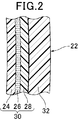
- FIG. 2 is an enlarged cross-sectional view of a cylindrical side wall portion of a double container manufactured by the double container manufacturing method of the first embodiment, taken along line II-II in FIG.
- FIG. 7 is an explanatory diagram of a process of forming an outer layer gap in the method for manufacturing a double container according to the first embodiment, taken along line VII-VII in FIG.
- FIG. 7 is an explanatory diagram of a process of forming an outer layer gap in the method for manufacturing a double container according to the first embodiment, taken along line VII-VII in FIG. 3, in which the split mold is in contact with the parison P.
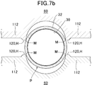
- FIG. 7 is an explanatory view of a process of forming an outer layer gap in the method for manufacturing a double container according to the first embodiment, taken along line VII-VII in FIG. 3, and shows a state in which the split mold starts to deform the parison P.
- FIG. 7 is an explanatory diagram of a process of forming an outer layer gap in the method for manufacturing a double container according to the first embodiment, taken along line VII-VII in FIG. 3, and shows a state in which the split mold starts to deform the parison P.
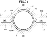
- FIG. 7 is an explanatory diagram of a process of forming an outer layer gap in the method for manufacturing a double container according to the first embodiment, taken along line VII-VII in FIG. 3, wherein the rigid outer layer and the flexible inner layer are sandwiched by the split mold It is.
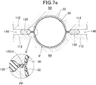
- FIG. 7 is an explanatory diagram of a process of forming the outer layer gap in the method for manufacturing the double container according to the first embodiment, taken along line VII-VII in FIG. 3, and the split mold is in a state in which a gap burr and a pinch part are formed.
- FIG. 8 is a longitudinal sectional view of the bottom portion taken along line VIII-VIII in FIG. 1.
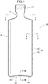
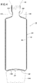
- the double container 10 manufactured by the manufacturing method of the first embodiment includes a mouth portion 12, a neck shoulder portion 14, a cylindrical portion 18, and a bottom portion 20.
- the cylindrical portion side surface 22 of the cylindrical portion 18 has a low-density polyethylene (LDPE) layer 24 from the inside, as shown in FIGS. It consists of an adhesive layer 26 such as a polyolefin-based adhesive resin, three flexible inner layers 30 of an ethylene vinyl alcohol copolymer (EVOH) layer 28, and a rigid outer layer 32 of polypropylene (PP). There is no adhesion between the flexible inner layer 30 and the rigid outer layer 32, and it can be easily peeled off.
- LDPE low-density polyethylene
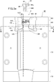
- a pair of partial molds 60 whose front view is shown in FIG. 3a is joined at a mating surface H (see FIG. 6) to form a split mold (not shown). And use it.
- the partial mold 60 includes a mouth burr region 64, a mouth region 66, a neck shoulder region 68, a cylindrical side wall region 70, and a bottom region 72.
- the burr portion region 64 cuts out an unnecessary upper end portion of the parison P indicated by an imaginary line.
- a mouth burr mold part 80 acting as a mold is made of a steel material SKD11 and embedded in an extended part of the cylindrical side wall part region 70 made of aluminum 7075.
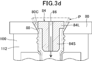
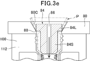
- the metal blow pin 84 partially inserted into the parison P has a large diameter cylindrical part 84L and a small diameter cylindrical part 84S, and blow air passes through the center.
- a vertical through hole 86 is provided.
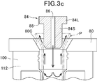
- the lower edge corner portion 88 of the large-diameter cylindrical portion 84 ⁇ / b> L of the blow pin 84 comes into contact with the parison P and the space between the blow pin 84 and the parison P is closed.
- the parison P is pressed against the mouth mold part 100 by the pressure of the air blown from the blow pin 84, and the mouth part is molded.
- the lower edge corner portion 88 of the large-diameter cylindrical portion 84 ⁇ / b> L of the blow pin 84 contacts the upper wide conical surface 80 ⁇ / b> C extending upward from the upper end portion 90 of the mouth portion mold portion 100. By this contact, the parison P is cut and the burr 92 is removed.
- the mouth area 66 forms a container mouth with a spiral mountain.
- the mouth mold part 100 is made of steel NAK55 and is embedded in an extension of the cylindrical side region 70 made of aluminum 7075. By blowing the blow air, the parison P is pressed against the inner surface of the mouth mold portion 100, and the mouth region 66 is formed.
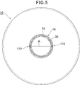
- the neck shoulder 14 of the double container 10 is rigid on a surface A corresponding to a mating surface H of a partial mold (none of which is shown in FIG. 5) constituting the split mold.
- the outer layer 32 is interrupted to form an outer layer gap 110, and the flexible inner layer 30 is exposed in the outer layer gap 110.
- the flexible inner layer 30 and the rigid outer layer 32 are not adhesive and can be easily peeled. Therefore, when the volume of the space created by the flexible inner layer 30 decreases, the flexible inner layer 30 becomes rigid. Peeling from the outer layer 32, the outside air enters between the flexible inner layer 30 and the rigid outer layer 32 from the outer layer gap 110.
- the neck shoulder mold portion 112 for molding the neck shoulder portion 14 of the double container 10 is integrally formed with the mouth mold portion 100 by a steel material NAK55. And is embedded in an extension of the cylindrical side region 70 made of aluminum 7075.
- the molding surface of the neck shoulder portion 14 is such that the innermost distance RS of the mating surface H of the portion 60 in which the outer layer gap 110 of the neck shoulder region 68 of the partial mold 60 is formed is compared with the parison P of the outer diameter R. It is 71.4% of the outer diameter R.
- the innermost distance RS of the mating surface H of the portion of the neck 60 in the neck / shoulder region 68 of the partial mold 60 is 99% to 50%, more preferably 95% to 60% of the outer diameter R. %, More preferably 95% to 70%.
- This interval RS is determined in consideration of the environmental temperature, the temperature of the parison P, the thickness and the diameter of the parison P, and the like so as to obtain the optimum size of the outer layer gap 110 and the ease of excision of gap burrs described later. It is done.
- the neck shoulder region 68 of the partial mold 60 for molding the neck shoulder 14 of the double container 10 is, as shown in FIGS. 6 and 7a, an inner diameter of the parison P of 17.0 mm and an outer diameter.
- R is 21.0 mm
- the outer diameter PR of the mouth portion 12 of the molded product is 21.5 mm
- the inner diameter is 17.3 mm
- the interval RS between the shoulder mold portions 112 is 15.0 mm (71.4% of the outer diameter of the parison P).
- the temperature of the parison P at the time of molding is 190.0 ° C.
- the mold temperature is 19.0 ° C.
- the sandwiching width on the mating surface H of the sandwiching portion 120 that attempts to create the outer layer gap 110 on the mating surface H is 0.2 mm.
- a gap burr recess 140 (see FIGS. 4 and 6) for forming a gap burr 130 is formed outside the sandwiched portion 120 on the mating surface H.
- the gap burr recess 140 has a depth D of 1.5 mm, and an inclined surface 142 inclined by 45 ° with respect to the mating surface H is formed around the entire gap burr recess 140.
- the process of forming the outer layer gap 110 of the double container 10 manufactured by the manufacturing method of the first embodiment is as follows. As shown in FIGS. 6 and 7 a, the parison P in a state where it can be molded is disposed so as to be aligned between a pair of facing partial molds 60.
- the pair of partial molds 60 for making the split mold is moved toward the parison P with respect to each other.
- the innermost portion M of the mating surface H of the partial mold 60 has an interval between the mating surfaces H of the pair of partial molds 60, for example, 8.0 mm.
- the left and right sides contact the outer peripheral surface of the parison P.
- the sandwiching portion 120 of the mating surface H includes the folded inner flexible layer 30 at the center portion and the rigid outer layers 32 on both sides thereof. Is inserted. The rigid outer layer 32 is crushed and extends to the inside of the gap burr recess 140.
- the adhesive inner layer 30 is bonded and integrated with each other.
- the interval between the sandwiching portions 120 of the mating surface H is about 0.05 to 0. .3mm.
- a gap burr 130 is formed through the pinch portion PP.
- the pinch part PP is a case where both surfaces of the mating surfaces of the partial molds of the split mold are flat, and when the split mold is formed by combining the partial molds, the mating surface is the parison P. The part of the very thin parison material sandwiched between the mating surfaces.
- the bottom 20 of the double container 10 is formed by sandwiching the middle part of the parison P with the bottom region 72 of the partial mold 60 when the partial mold 60 is combined to form a split mold.
- the portion of the bottom region 72 that acts as a mold is made of steel NAK 55, similar to the mouth mold portion 100 and neck shoulder mold portion 112, and is embedded in an extension of the cylindrical side region 70 made of aluminum 7075. It is.
- a bottom burr 144 is formed in the parison P below the bottom 20 via the pinch portion PP.
- the central transverse portion of the bottom portion 20 is integrated by pressing the parisons P in the front-rear direction region of the mating surface H of the split mold against each other, and outer layers 32 exist on both sides of the integrated portion. To do. Therefore, as it is, since there is no adhesion between the flexible inner layer 30 and the rigid outer layer 32 and it can be easily peeled off, there is a high possibility that a gap is formed between the flexible inner layer 30 and the rigid outer layer 32 in the bottom portion 20. There is a risk of unfavorable situations such as inhaling water from this gap. In order to remove this fear, the ends of the flexible inner layer 30 and the rigid outer layer 32 at the bottom 20 are covered with an adhesive 150.
- the intermediate product of the double container manufactured by the method described above easily removes the gap burr 130 and the bottom burr 144 supported by the pinch part PP, and the double container is completed.
- the double container 10 manufactured by the manufacturing method of the second embodiment includes a flexible inner layer 30 of polyamide (PA) and a rigid outer layer 32 of polypropylene (PP). There is no adhesion between the flexible inner layer 30 and the rigid outer layer 32, and it can be easily peeled off.
- PA polyamide
- PP polypropylene
- the neck shoulder region 68 of the partial mold 60 for molding the neck shoulder 14 of the double container 10 has an inner diameter of the parison P of 16.5 mm, an outer diameter R of 20.5 mm, and an outer diameter of the mouth 12 of the molded product.
- the PR is 21.5 mm and the inner diameter is 17.3 mm
- the minimum diameter portion of the mating surface H of the neck shoulder 14 where the outer layer gap 110 is to be made, that is, the distance RS between the neck shoulder mold portions 112 is 15.5 mm ( 72.1% of the outer diameter of the parison P).
- the temperature of the parison P during molding is 190.0 ° C., and the mold temperature is 19.0 ° C.
- the sandwiching width on the mating surface H of the sandwiching portion 120 to create the outer layer gap 110 on the mating surface H is 0.1 mm.
- a gap burr recess 140 (see FIG. 6) for forming a gap burr 130 is formed outside the sandwiched portion 120 on the mating surface H.
- the gap flash recess 140 has a depth D of 2.0 mm, and a slope 142 inclined by 30 ° with respect to the mating surface H is formed around the entire gap burr recess 140.
- the double container manufactured by the manufacturing method of the third embodiment includes, from the inside, a low-density polyethylene (LDPE) layer, an adhesive layer such as a polyolefin-based adhesive resin, and an ethylene vinyl alcohol copolymer (EVOH) layer.
- LDPE low-density polyethylene
- EVOH ethylene vinyl alcohol copolymer
- the mouth mold portion 100 and the neck shoulder mold portion 112 are integrally made of die steel SKD11.
- the neck shoulder region 68 of the partial mold 60 for molding the neck shoulder 14 of the double container 10 has an inner diameter of the parison P of 23.5 mm, an outer diameter R of 28.5 mm, and an outer diameter of the mouth 12 of the molded product.
- the PR is 29.0 mm and the inner diameter is 23.5 mm
- the minimum diameter portion of the mating surface H of the neck shoulder 14 where the outer layer gap 110 is to be formed, that is, the distance RS between the neck shoulder mold portions 112 is 20.0 mm ( 70.1% of the outer diameter of the parison P).
- the temperature of the parison P during molding is 210.0 ° C., and the mold temperature is 19.0 ° C.
- the sandwiching width on the mating surface H of the sandwiching portion 120 to create the outer layer gap 110 on the mating surface H is 0.1 mm.
- a gap burr recess 140 (see FIG. 6) for forming a gap burr 130 is formed outside the sandwiched portion 120 on the mating surface H.
- the gap burr recess 140 has a depth D of 2.0 mm, and an inclined surface 142 inclined by 30 ° with respect to the mating surface H is formed around the entire gap burr recess 140.
- the double container manufactured by the manufacturing method of the fourth embodiment includes, from the inside, a blend layer of low density polyethylene (LDPE) and an adhesive resin, an ethylene vinyl alcohol copolymer (EVOH), a polyolefin adhesive resin, and the like.
- Adhesive layer Adhesive layer, four flexible inner layers 30 of ethylene vinyl alcohol copolymer (EVOH), and a rigid outer layer 32 of polypropylene (PP).
- PP polypropylene
- the neck shoulder region 68 of the partial mold 60 for molding the neck shoulder 14 of the double container 10 has an inner diameter of the parison P of 15.5 mm, an outer diameter R of 20.0 mm, and an outer diameter of the mouth 12 of the molded product.
- the PR is 20.5 mm and the inner diameter is 17.3 mm
- the smallest diameter portion of the mating surface H of the neck shoulder 14 where the outer layer gap 110 is to be made, that is, the distance RS between the neck shoulder mold portions 112 is 13.0 mm. (65.0% of the outer diameter of the parison P).
- the temperature of the parison P during molding is 190.0 ° C., and the mold temperature is 19.0 ° C.
- the sandwiching width on the mating surface H of the sandwiching portion 120 to create the outer layer gap 110 on the mating surface H is 0.1 mm.
- a gap burr recess 140 (see FIG. 6) for forming a gap burr 130 is formed outside the sandwiched portion 120 on the mating surface H.
- the gap burr recess 140 has a depth D of 1.5 mm, and an inclined surface 142 inclined by 60 ° with respect to the mating surface H is formed on the entire periphery of the gap burr recess 140.
- the gap burr recess 140 is formed on the mating surface H.
- an excess parison recess 500 for receiving the parison material protruding from the split mold at the time of blowing can be formed in the vicinity of the mouth burr part region 64, the mouth region 66, and the like (see FIG. 3).
Landscapes
- Engineering & Computer Science (AREA)
- Mechanical Engineering (AREA)
- Manufacturing & Machinery (AREA)
- Blow-Moulding Or Thermoforming Of Plastics Or The Like (AREA)
- Moulds For Moulding Plastics Or The Like (AREA)
Abstract
Description
すなわち、一般の容器において、収容物の充填後、容器内の空間を真空にしたり窒素ガス等の不活性ガスを充填すること等によって、充填容器を開封するまで収容物の酸化を防ぐことは容易である。しかし、一般的には、容器を開封して収容物を一部消費し、容器内に使用残りの収容物が残留している状態では、容器内に収容物の消費量に対応した容積の外気が入り、残留収容物が酸化する。この酸化を防ぐため、収容物に酸化防止剤を含有することもある。
本発明は、比較的剛性な外容器と、該外容器内で収容物の充填量に対応して容量を変更可能な柔軟内容器とからなる二重容器において、特に外気を入れるための開口に関する上述した問題点に鑑みてなされたものであって、従来と大きく変わらない成形装置によって容易に製造可能で、比較的剛性な外容器と、該外容器内で収容物の充填量に対応して容量を変更可能な二重容器において外気を入れるための開口を、極めて容易に且つ確実に、従来技術による加工コストより低いコストで形成することができる二重容器の製造方法を提供することを目的とする。
成形後互いに剥離可能な剛性外層容器部と柔軟性内層容器部とを形成する内層及び外層の少なくとも2層を有するパリソンから、一対の部分金型を組み合わせた割金型を使用して容器を成形し、前記剛性外層容器部と前記柔軟性内層容器部との間に外気を導入して、前記剛性外層容器部の形状を維持しながら、前記柔軟性内層容器部の容量を縮小させる二重容器の製造方法において、
前記一対の部分金型が組み合わされて前記割金型を作るために相互に近寄る際に、前記一対の部分金型の合わせ面の一部が、パリソンの前記剛性外層と前記柔軟性内層を水平対向位置の両側部分で挟み込むことを特徴とする二重容器の製造方法
である。
成形後互いに剥離可能な剛性外層容器部と柔軟性内層容器部とを形成する内層及び外層の少なくとも2層を有するパリソンから、一対の部分金型を組み合わせた割金型を使用して容器を成形し、前記剛性外層容器部と前記柔軟性内層容器部との間に外気を導入して、前記剛性外層容器部の形状を維持しながら、前記柔軟性内層容器部の容量を縮小させる二重容器の製造方法において、
前記一対の部分金型が組み合わされて前記割金型を作るために相互に近寄る際に、前記一対の部分金型の合わせ面におけるパリソンの円筒外面の接触面と直交する部分が、前記二重容器の上方半分の領域内でパリソンを挟み込むことを特徴とする二重容器の製造方法である。
前記本発明において、前記一対の部分金型の合わせ面の少なくとも一部が、パリソンの剛性外層を水平対向位置の両側部分で挟み込むことを特徴とする。
(発明の第2実施態様)
前記本発明において、前記一対の部分金型の合わせ面の少なくとも一部が、パリソンの剛性外層と柔軟性内層を水平対向位置の両側部分で挟み込むことを特徴とする。
(発明の第3実施態様)
前記本発明において、前記一対の部分金型の合わせ面の一部が前記パリソンを挟み込む部分の外側に、前記パリソンから作られる摘み突起部を形成することを特徴とする。
(発明の第4実施態様)
前記本発明において、前記一対の部分金型の当たり面の一部が前記パリソンを挟み込む部分は、二重容器の首肩部であることを特徴とする。
(発明の第5実施態様)
前記本発明において、前記一対の部分金型の当たり面の一部が前記パリソンを挟み込む部分は、二重容器の口部であることを特徴とする。
(発明の第6実施態様)
前記本発明において、前記一対の部分金型の当たり面の一部が前記パリソンを挟み込む部分は、二重容器の螺合口部であることを特徴とする。
第1実施形態の製造方法によって製造される二重容器10は、口部12,首肩部14、円筒部18,及び底部20からなる。
続いて、図3cに示すように、パリソンP内にエアがブローピン84から吹き込まれると、パリソンPの上方端部分が吹き出るエアによって上広形に押し広げられる。
続いて、ブローピン84の大径筒部分84Lの下縁角部88が口部金型部分100の上端部90から上方へ延びる上広円錐面80Cに当接する。この当接によって、パリソンPが切断されて、口バリ92が除去される。
成形可能な状態のパリソンPを、図6及び図7aに示すように、向き合った一対の部分金型60の間に芯合わせして配置する。
底部20の中央横断部は、図8に示すように、割金型の合わせ面Hの前後方向の領域のパリソンPが互いに押し付けられて一体化し、該一体化した部分の両側に外層32が存在する。従って、このままでは、柔軟性内層30と剛性外層32の間に接着性がなく容易に剥離可能であるから、底部20における柔軟性内層30と剛性外層32の間に隙間ができる可能性が高い。この隙間から水等を吸い込む等好ましくない状況になる恐れがある。この恐れを取り除くため、底部20における柔軟性内層30と剛性外層32の端部を接着剤150によって覆い被せている。
第2実施形態の製造方法によって製造される二重容器10は、ポリアミド(PA)の柔軟性内層30と、ポリプロピレン(PP)の剛性外層32とからなる。柔軟性内層30と剛性外層32の間には、接着性はなく、容易に剥離可能である。
第3実施形態の製造方法によって製造される二重容器は、内側から、低密度ポリエチレン(LDPE)層、ポリオフィン系接着性樹脂等の接着剤層、及びエチレンビニルアルコール共重合体(EVOH)層の3層の柔軟性内層30と、ポリカーボネート(PC)の剛性外層32とからなる。柔軟性内層30と剛性外層32の間には、接着性はなく、容易に剥離可能である。
口部金型部分100及び首肩部金型部分112は、一体的に、ダイス鋼SKD11によって作られる。
第4実施形態の製造方法によって製造される二重容器は、内側から、低密度ポリエチレン(LDPE)と接着性樹脂のブレンド層、エチレンビニルアルコール共重合体(EVOH)、ポリオフィン系接着性樹脂等の接着剤層、及びエチレンビニルアルコール共重合体(EVOH)の4層の柔軟性内層30と、ポリプロピレン(PP)の剛性外層32とからなる。柔軟性内層30と剛性外層32の間には、接着性はなく、容易に剥離可能である。
口部金型部分100及び首肩部金型部分112は、一体的に、プリハードン鋼(NAK55)によって作られる。
PP ピンチ部
10 二重容器
18 円筒部
22 円筒部側面
24 低密度ポリエチレン(LDPE)層
26 接着剤層
28 エチレンビニルアルコール共重合体(EVOH)層
30 柔軟性内層
32 剛性外層
60 部分金型
64 口バリ部領域
66 口部領域
68 首肩部領域
70 円筒側壁部領域
72 底部領域
80 口バリ金型部分
84 ピン
86 縦貫通孔
88 下縁角部
92 口バリ
100 口部金型部分
110 外層隙間
112 首肩部金型部分
120 挟み部分
130 隙間バリ
140 隙間バリ凹部
142 斜面
144 底バリ
500 余剰パリソン凹部
Claims (8)
- 成形後互いに剥離可能な剛性外層容器部と柔軟性内層容器部とを形成する内層及び外層の少なくとも2層を有するパリソンから、一対の部分金型を組み合わせた割金型を使用して容器を成形し、前記剛性外層容器部と前記柔軟性内層容器部との間に外気を導入して、前記剛性外層容器部の形状を維持しながら、前記柔軟性内層容器部の容量を縮小させる二重容器の製造方法において、
前記一対の部分金型が組み合わされて前記割金型を作るために相互に近寄る際に、前記一対の部分金型の合わせ面の少なくとも一部が、パリソンを水平対向位置の両側部分で挟み込むことを特徴とする二重容器の製造方法。 - 前記一対の部分金型の合わせ面の少なくとも一部が、パリソンの剛性外層を水平対向位置の両側部分で挟み込むことを特徴とする請求項1に記載の二重容器の製造方法。
- 前記一対の部分金型の合わせ面の少なくとも一部が、パリソンの剛性外層と柔軟性内層を水平対向位置の両側部分で挟み込むことを特徴とする請求項1に記載の二重容器の製造方法。
- 前記一対の部分金型の合わせ面の一部が前記パリソンを挟み込む部分の外側に、前記パリソンから作られる摘み突起部を形成することを特徴とする請求項1に記載の二重容器の製造方法。
- 前記一対の部分金型の当たり面の一部が前記パリソンを挟み込む部分は、二重容器の首肩部であることを特徴とする請求項1に記載の二重容器の製造方法。
- 前記一対の部分金型の当たり面の一部が前記パリソンを挟み込む部分は、二重容器の口部であることを特徴とする請求項1に記載の二重容器の製造方法。
- 前記一対の部分金型の当たり面の一部が前記パリソンを挟み込む部分は、二重容器の螺合口部であることを特徴とする請求項1に記載の二重容器の製造方法。
- 成形後互いに剥離可能な剛性外層容器部と柔軟性内層容器部とを形成する内層及び外層の少なくとも2層を有するパリソンから、一対の部分金型を組み合わせた割金型を使用して容器を成形し、前記剛性外層容器部と前記柔軟性内層容器部との間に外気を導入して、前記剛性外層容器部の形状を維持しながら、前記柔軟性内層容器部の容量を縮小させる二重容器の製造方法において、
前記一対の部分金型が組み合わされて前記割金型を作るために相互に近寄る際に、前記一対の部分金型の合わせ面におけるパリソンの円筒外面の接触面と直交する部分が、前記二重容器の上方半分の領域内でパリソンを挟み込むことを特徴とする二重容器の製造方法。
Priority Applications (4)
| Application Number | Priority Date | Filing Date | Title |
|---|---|---|---|
| US15/504,468 US10518462B2 (en) | 2014-08-19 | 2015-08-11 | Double-walled container manufacturing method |
| CN201580043680.8A CN106660255B (zh) | 2014-08-19 | 2015-08-11 | 双层容器的制造方法 |
| KR1020177005898A KR101985609B1 (ko) | 2014-08-19 | 2015-08-11 | 이중 용기의 제조 방법 |
| EP15833611.5A EP3184280B1 (en) | 2014-08-19 | 2015-08-11 | Double-walled container manufacturing method |
Applications Claiming Priority (2)
| Application Number | Priority Date | Filing Date | Title |
|---|---|---|---|
| JP2014-166829 | 2014-08-19 | ||
| JP2014166829A JP6516122B2 (ja) | 2014-08-19 | 2014-08-19 | 二重容器の製造方法 |
Publications (1)
| Publication Number | Publication Date |
|---|---|
| WO2016027732A1 true WO2016027732A1 (ja) | 2016-02-25 |
Family
ID=55350677
Family Applications (1)
| Application Number | Title | Priority Date | Filing Date |
|---|---|---|---|
| PCT/JP2015/072726 Ceased WO2016027732A1 (ja) | 2014-08-19 | 2015-08-11 | 二重容器の製造方法 |
Country Status (6)
| Country | Link |
|---|---|
| US (1) | US10518462B2 (ja) |
| EP (1) | EP3184280B1 (ja) |
| JP (1) | JP6516122B2 (ja) |
| KR (1) | KR101985609B1 (ja) |
| CN (1) | CN106660255B (ja) |
| WO (1) | WO2016027732A1 (ja) |
Families Citing this family (8)
| Publication number | Priority date | Publication date | Assignee | Title |
|---|---|---|---|---|
| JP6735112B2 (ja) * | 2016-02-16 | 2020-08-05 | 株式会社平和化学工業所 | 二重容器及びその製造方法 |
| JP6855126B2 (ja) * | 2017-05-31 | 2021-04-07 | 株式会社吉野工業所 | 合成樹脂製容器 |
| JP7365758B2 (ja) * | 2018-01-30 | 2023-10-20 | 株式会社吉野工業所 | 積層剥離容器 |
| IT201900007764A1 (it) * | 2019-05-31 | 2020-12-01 | Alphamac S R L | Apparato e metodo per la formatura di contenitori cavi |
| EP3991937B1 (en) * | 2019-06-28 | 2024-10-23 | Nissei Asb Machine Co., Ltd. | Apparatus for producing resin molded article, method for producing resin molded article, and resin molded article |
| US12172349B2 (en) * | 2019-09-06 | 2024-12-24 | Dow Global Technologies Llc | Flexible film fluid-dispensing device |
| CN110802830A (zh) * | 2019-09-26 | 2020-02-18 | 广东炜田环保新材料股份有限公司 | 一种新型强化边缘吹塑制备方法 |
| USD996972S1 (en) * | 2021-03-29 | 2023-08-29 | Owens-Brockway Glass Container Inc. | Container |
Citations (2)
| Publication number | Priority date | Publication date | Assignee | Title |
|---|---|---|---|---|
| JPH06155560A (ja) * | 1991-12-27 | 1994-06-03 | Nippon Steel Chem Co Ltd | 多層ブロー成形方法及びその装置並びにこの方法で得られた中空成形品 |
| JP2009012786A (ja) * | 2007-06-29 | 2009-01-22 | Yoshino Kogyosho Co Ltd | 積層剥離容器 |
Family Cites Families (15)
| Publication number | Priority date | Publication date | Assignee | Title |
|---|---|---|---|---|
| JPS5228540B2 (ja) | 1972-08-04 | 1977-07-27 | ||
| JPS627946A (ja) | 1985-07-04 | 1987-01-14 | Toyota Motor Corp | 内燃機関の燃料噴射制御装置 |
| CA2003034C (en) * | 1988-11-30 | 1994-05-24 | Akira Ohta | Blow molding mold for forming hollow double-walled product and blow molding apparatus using such mold |
| WO1993002926A1 (fr) * | 1991-08-05 | 1993-02-18 | Yoshino Kogyosho Co., Ltd. | Bouteille a structure stratifiee et procede de fabrication d'une telle bouteille |
| US5460772A (en) | 1991-12-27 | 1995-10-24 | Nippon Steel Chemical Co., Ltd. | Process for multilayer blow molding |
| JP3368484B2 (ja) | 1994-06-23 | 2003-01-20 | 株式会社吉野工業所 | 壜体およびその成形方法 |
| JP3627946B2 (ja) | 1996-07-29 | 2005-03-09 | 株式会社吉野工業所 | 二層容器 |
| CN1122626C (zh) * | 2000-10-05 | 2003-10-01 | 佳能株式会社 | 液体容器及其制造方法,以及用于液体容器制造方法的金属模具 |
| FR2853276B1 (fr) * | 2003-04-02 | 2007-05-18 | Plastohm Sa | Procede de realisation d'une reprise d'air dans un recipient multiparois |
| JP2006335398A (ja) | 2005-05-31 | 2006-12-14 | Yoshino Kogyosho Co Ltd | 内側層が剥離可能な積層容器その成形方法 |
| JP4936249B2 (ja) | 2007-02-28 | 2012-05-23 | 株式会社吉野工業所 | 合成樹脂製ブロー成形容器 |
| JP5641430B2 (ja) | 2011-01-31 | 2014-12-17 | 株式会社吉野工業所 | ブロー成形壜体 |
| WO2012137945A1 (ja) | 2011-04-06 | 2012-10-11 | 株式会社大塚製薬工場 | プラスチックアンプル |
| JP6112385B2 (ja) * | 2012-08-31 | 2017-04-12 | 株式会社吉野工業所 | ブロー成形容器及びその製造方法 |
| JP6025040B2 (ja) | 2012-10-31 | 2016-11-16 | 株式会社吉野工業所 | ブロー成形容器及びブロー成形方法 |
-
2014
- 2014-08-19 JP JP2014166829A patent/JP6516122B2/ja active Active
-
2015
- 2015-08-11 US US15/504,468 patent/US10518462B2/en active Active
- 2015-08-11 KR KR1020177005898A patent/KR101985609B1/ko active Active
- 2015-08-11 WO PCT/JP2015/072726 patent/WO2016027732A1/ja not_active Ceased
- 2015-08-11 CN CN201580043680.8A patent/CN106660255B/zh not_active Expired - Fee Related
- 2015-08-11 EP EP15833611.5A patent/EP3184280B1/en active Active
Patent Citations (2)
| Publication number | Priority date | Publication date | Assignee | Title |
|---|---|---|---|---|
| JPH06155560A (ja) * | 1991-12-27 | 1994-06-03 | Nippon Steel Chem Co Ltd | 多層ブロー成形方法及びその装置並びにこの方法で得られた中空成形品 |
| JP2009012786A (ja) * | 2007-06-29 | 2009-01-22 | Yoshino Kogyosho Co Ltd | 積層剥離容器 |
Non-Patent Citations (1)
| Title |
|---|
| See also references of EP3184280A4 * |
Also Published As
| Publication number | Publication date |
|---|---|
| JP6516122B2 (ja) | 2019-05-22 |
| KR101985609B1 (ko) | 2019-06-03 |
| KR20170041235A (ko) | 2017-04-14 |
| US10518462B2 (en) | 2019-12-31 |
| CN106660255B (zh) | 2020-03-17 |
| CN106660255A (zh) | 2017-05-10 |
| US20170239873A1 (en) | 2017-08-24 |
| EP3184280A4 (en) | 2018-02-21 |
| EP3184280A1 (en) | 2017-06-28 |
| EP3184280B1 (en) | 2021-04-07 |
| JP2016043489A (ja) | 2016-04-04 |
Similar Documents
| Publication | Publication Date | Title |
|---|---|---|
| WO2016027732A1 (ja) | 二重容器の製造方法 | |
| US11427368B2 (en) | Manufacturing method for double walled container | |
| TWI766934B (zh) | 層疊剝離容器 | |
| WO2017073606A1 (ja) | 二重容器及びその製造方法 | |
| JP6421458B2 (ja) | 積層剥離容器 | |
| WO2017142027A1 (ja) | 二重容器及びその製造方法 | |
| JP2015160651A (ja) | 積層剥離容器の加工方法 | |
| JP2019099212A (ja) | 積層剥離容器 | |
| JP6806986B2 (ja) | 成形品並びにその製造方法及び製造装置 | |
| HK1234705B (zh) | 双层容器的制造方法 | |
| HK1234705A1 (en) | Double-walled container manufacturing method | |
| HK1262191B (en) | Double-layered container and method for production of same | |
| HK1262191A1 (en) | Double-layered container and method for production of same |
Legal Events
| Date | Code | Title | Description |
|---|---|---|---|
| 121 | Ep: the epo has been informed by wipo that ep was designated in this application |
Ref document number: 15833611 Country of ref document: EP Kind code of ref document: A1 |
|
| WWE | Wipo information: entry into national phase |
Ref document number: 15504468 Country of ref document: US |
|
| NENP | Non-entry into the national phase |
Ref country code: DE |
|
| ENP | Entry into the national phase |
Ref document number: 20177005898 Country of ref document: KR Kind code of ref document: A |
|
| REEP | Request for entry into the european phase |
Ref document number: 2015833611 Country of ref document: EP |
|
| WWE | Wipo information: entry into national phase |
Ref document number: 2015833611 Country of ref document: EP |