WO2016031050A1 - 車両のロックアップクラッチ制御装置 - Google Patents
車両のロックアップクラッチ制御装置 Download PDFInfo
- Publication number
- WO2016031050A1 WO2016031050A1 PCT/JP2014/072744 JP2014072744W WO2016031050A1 WO 2016031050 A1 WO2016031050 A1 WO 2016031050A1 JP 2014072744 W JP2014072744 W JP 2014072744W WO 2016031050 A1 WO2016031050 A1 WO 2016031050A1
- Authority
- WO
- WIPO (PCT)
- Prior art keywords
- lockup
- lock
- engine
- clutch
- time
- Prior art date
- Legal status (The legal status is an assumption and is not a legal conclusion. Google has not performed a legal analysis and makes no representation as to the accuracy of the status listed.)
- Ceased
Links
Images



Classifications
-
- F—MECHANICAL ENGINEERING; LIGHTING; HEATING; WEAPONS; BLASTING
- F16—ENGINEERING ELEMENTS AND UNITS; GENERAL MEASURES FOR PRODUCING AND MAINTAINING EFFECTIVE FUNCTIONING OF MACHINES OR INSTALLATIONS; THERMAL INSULATION IN GENERAL
- F16D—COUPLINGS FOR TRANSMITTING ROTATION; CLUTCHES; BRAKES
- F16D48/00—External control of clutches
- F16D48/06—Control by electric or electronic means, e.g. of fluid pressure
-
- F—MECHANICAL ENGINEERING; LIGHTING; HEATING; WEAPONS; BLASTING
- F16—ENGINEERING ELEMENTS AND UNITS; GENERAL MEASURES FOR PRODUCING AND MAINTAINING EFFECTIVE FUNCTIONING OF MACHINES OR INSTALLATIONS; THERMAL INSULATION IN GENERAL
- F16D—COUPLINGS FOR TRANSMITTING ROTATION; CLUTCHES; BRAKES
- F16D48/00—External control of clutches
- F16D48/02—Control by fluid pressure
-
- F—MECHANICAL ENGINEERING; LIGHTING; HEATING; WEAPONS; BLASTING
- F16—ENGINEERING ELEMENTS AND UNITS; GENERAL MEASURES FOR PRODUCING AND MAINTAINING EFFECTIVE FUNCTIONING OF MACHINES OR INSTALLATIONS; THERMAL INSULATION IN GENERAL
- F16H—GEARING
- F16H61/00—Control functions within control units of change-speed- or reversing-gearings for conveying rotary motion ; Control of exclusively fluid gearing, friction gearing, gearings with endless flexible members or other particular types of gearing
- F16H61/14—Control of torque converter lock-up clutches
-
- B—PERFORMING OPERATIONS; TRANSPORTING
- B60—VEHICLES IN GENERAL
- B60W—CONJOINT CONTROL OF VEHICLE SUB-UNITS OF DIFFERENT TYPE OR DIFFERENT FUNCTION; CONTROL SYSTEMS SPECIALLY ADAPTED FOR HYBRID VEHICLES; ROAD VEHICLE DRIVE CONTROL SYSTEMS FOR PURPOSES NOT RELATED TO THE CONTROL OF A PARTICULAR SUB-UNIT
- B60W10/00—Conjoint control of vehicle sub-units of different type or different function
- B60W10/02—Conjoint control of vehicle sub-units of different type or different function including control of driveline clutches
-
- B—PERFORMING OPERATIONS; TRANSPORTING
- B60—VEHICLES IN GENERAL
- B60W—CONJOINT CONTROL OF VEHICLE SUB-UNITS OF DIFFERENT TYPE OR DIFFERENT FUNCTION; CONTROL SYSTEMS SPECIALLY ADAPTED FOR HYBRID VEHICLES; ROAD VEHICLE DRIVE CONTROL SYSTEMS FOR PURPOSES NOT RELATED TO THE CONTROL OF A PARTICULAR SUB-UNIT
- B60W10/00—Conjoint control of vehicle sub-units of different type or different function
- B60W10/04—Conjoint control of vehicle sub-units of different type or different function including control of propulsion units
- B60W10/06—Conjoint control of vehicle sub-units of different type or different function including control of propulsion units including control of combustion engines
-
- F—MECHANICAL ENGINEERING; LIGHTING; HEATING; WEAPONS; BLASTING
- F16—ENGINEERING ELEMENTS AND UNITS; GENERAL MEASURES FOR PRODUCING AND MAINTAINING EFFECTIVE FUNCTIONING OF MACHINES OR INSTALLATIONS; THERMAL INSULATION IN GENERAL
- F16D—COUPLINGS FOR TRANSMITTING ROTATION; CLUTCHES; BRAKES
- F16D2500/00—External control of clutches by electric or electronic means
- F16D2500/10—System to be controlled
- F16D2500/104—Clutch
- F16D2500/10406—Clutch position
- F16D2500/10412—Transmission line of a vehicle
-
- F—MECHANICAL ENGINEERING; LIGHTING; HEATING; WEAPONS; BLASTING
- F16—ENGINEERING ELEMENTS AND UNITS; GENERAL MEASURES FOR PRODUCING AND MAINTAINING EFFECTIVE FUNCTIONING OF MACHINES OR INSTALLATIONS; THERMAL INSULATION IN GENERAL
- F16D—COUPLINGS FOR TRANSMITTING ROTATION; CLUTCHES; BRAKES
- F16D2500/00—External control of clutches by electric or electronic means
- F16D2500/30—Signal inputs
- F16D2500/302—Signal inputs from the actuator
- F16D2500/3024—Pressure
-
- F—MECHANICAL ENGINEERING; LIGHTING; HEATING; WEAPONS; BLASTING
- F16—ENGINEERING ELEMENTS AND UNITS; GENERAL MEASURES FOR PRODUCING AND MAINTAINING EFFECTIVE FUNCTIONING OF MACHINES OR INSTALLATIONS; THERMAL INSULATION IN GENERAL
- F16D—COUPLINGS FOR TRANSMITTING ROTATION; CLUTCHES; BRAKES
- F16D2500/00—External control of clutches by electric or electronic means
- F16D2500/30—Signal inputs
- F16D2500/304—Signal inputs from the clutch
- F16D2500/30401—On-off signal indicating the engage or disengaged position of the clutch
-
- F—MECHANICAL ENGINEERING; LIGHTING; HEATING; WEAPONS; BLASTING
- F16—ENGINEERING ELEMENTS AND UNITS; GENERAL MEASURES FOR PRODUCING AND MAINTAINING EFFECTIVE FUNCTIONING OF MACHINES OR INSTALLATIONS; THERMAL INSULATION IN GENERAL
- F16D—COUPLINGS FOR TRANSMITTING ROTATION; CLUTCHES; BRAKES
- F16D2500/00—External control of clutches by electric or electronic means
- F16D2500/70—Details about the implementation of the control system
- F16D2500/704—Output parameters from the control unit; Target parameters to be controlled
- F16D2500/70422—Clutch parameters
- F16D2500/70426—Clutch slip
-
- F—MECHANICAL ENGINEERING; LIGHTING; HEATING; WEAPONS; BLASTING
- F16—ENGINEERING ELEMENTS AND UNITS; GENERAL MEASURES FOR PRODUCING AND MAINTAINING EFFECTIVE FUNCTIONING OF MACHINES OR INSTALLATIONS; THERMAL INSULATION IN GENERAL
- F16D—COUPLINGS FOR TRANSMITTING ROTATION; CLUTCHES; BRAKES
- F16D2500/00—External control of clutches by electric or electronic means
- F16D2500/70—Details about the implementation of the control system
- F16D2500/704—Output parameters from the control unit; Target parameters to be controlled
- F16D2500/70452—Engine parameters
- F16D2500/70458—Engine torque
-
- F—MECHANICAL ENGINEERING; LIGHTING; HEATING; WEAPONS; BLASTING
- F16—ENGINEERING ELEMENTS AND UNITS; GENERAL MEASURES FOR PRODUCING AND MAINTAINING EFFECTIVE FUNCTIONING OF MACHINES OR INSTALLATIONS; THERMAL INSULATION IN GENERAL
- F16H—GEARING
- F16H61/00—Control functions within control units of change-speed- or reversing-gearings for conveying rotary motion ; Control of exclusively fluid gearing, friction gearing, gearings with endless flexible members or other particular types of gearing
- F16H61/14—Control of torque converter lock-up clutches
- F16H61/143—Control of torque converter lock-up clutches using electric control means
- F16H2061/145—Control of torque converter lock-up clutches using electric control means for controlling slip, e.g. approaching target slip value
-
- F—MECHANICAL ENGINEERING; LIGHTING; HEATING; WEAPONS; BLASTING
- F16—ENGINEERING ELEMENTS AND UNITS; GENERAL MEASURES FOR PRODUCING AND MAINTAINING EFFECTIVE FUNCTIONING OF MACHINES OR INSTALLATIONS; THERMAL INSULATION IN GENERAL
- F16H—GEARING
- F16H61/00—Control functions within control units of change-speed- or reversing-gearings for conveying rotary motion ; Control of exclusively fluid gearing, friction gearing, gearings with endless flexible members or other particular types of gearing
- F16H61/14—Control of torque converter lock-up clutches
- F16H61/143—Control of torque converter lock-up clutches using electric control means
- F16H2061/146—Control of torque converter lock-up clutches using electric control means for smoothing gear shift shock
Definitions
- the present invention relates to a lockup clutch control device for a vehicle for fastening a lockup clutch of a torque converter when starting.
- the present invention has been made paying attention to the above problem, and an object of the present invention is to provide a vehicle lock-up clutch control device that suppresses engine run-up when the lock-up clutch is fastened at the start.
- the present invention includes a torque converter having a lock-up clutch between an engine and a transmission.
- a start-up lockup control means is provided for delaying an increase in the lockup command pressure while the original pressure of the lockup actual hydraulic pressure is increasing.
- the start-up lockup control means reduces the torque of the engine at least during the delay of the lockup command pressure.
- the lockup clutch when the lockup clutch is engaged at the start, the increase in the lockup command pressure is delayed while the original pressure of the lockup actual hydraulic pressure is increasing. Then, at least during the delay of the lockup command pressure, the engine torque is reduced. That is, during the delay of the lockup command pressure that does not generate the lockup capacity, the engine torque is reduced, whereby the engine torque is reduced and the engine speed-up is suppressed. As a result, when the lock-up clutch is fastened at the time of starting, it is possible to suppress the engine speed-up.
- FIG. 1 is an overall system diagram showing an engine vehicle to which a lockup clutch control device of Embodiment 1 is applied. It is a flowchart which shows the flow of the lockup control process at the time of start performed by the CVT control unit of Example 1.
- FIG. 3 is a block diagram illustrating target lockup capacity calculation processing in lockup capacity control in the first embodiment.
- It is a time chart which shows a characteristic.
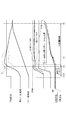
- accelerator opening, target engine speed, actual engine speed, turbine speed, target slip speed, target engine torque, actual engine torque, when starting by cooperative control of command pressure delay and engine torque reduction It is a time chart which shows each characteristic of line pressure, lockup command pressure, and lockup actual oil pressure. It is a flowchart which shows the flow of the lockup control process at the time of start performed by the CVT control unit of Example 2. It is a flowchart which shows the flow of the lockup control process at the time of start performed by the CVT control unit of Example 3.
- the configuration of the vehicle lockup clutch control device according to the first embodiment will be described by dividing it into an “overall system configuration” and a “startup lockup control configuration”.
- FIG. 1 shows an engine vehicle to which the lockup clutch control device of the first embodiment is applied.
- the overall system configuration will be described below with reference to FIG.
- the vehicle drive system includes an engine 1, an engine output shaft 2, a lock-up clutch 3, a torque converter 4, a transmission input shaft 5, and a continuously variable transmission 6 (transmission).
- the drive shaft 7 and the drive wheel 8 are provided.
- the lock-up clutch 3 is built in the torque converter 4 and connects the engine 1 and the continuously variable transmission 6 via the torque converter 4 when the clutch is released, and directly connects the engine output shaft 2 and the transmission input shaft 5 when the clutch is engaged. To do.
- a lock-up command pressure is output from the CVT control unit 12 described later, the lock-up clutch 3 is engaged / slip engaged / released by the lock-up actual hydraulic pressure adjusted based on the line pressure that is the original pressure. Be controlled.
- the line pressure is generated by regulating the discharge oil from an oil pump (not shown) that is rotationally driven by the engine 1 using a line pressure solenoid valve.
- the torque converter 4 includes a pump impeller 41, a turbine runner 42 disposed opposite to the pump impeller 41, and a stator 43 disposed between the pump impeller 41 and the turbine runner 42.
- the torque converter 4 is a fluid coupling that transmits torque by circulating hydraulic oil filled therein through the blades of the pump impeller 41, the turbine runner 42, and the stator 43.
- the pump impeller 41 is connected to the engine output shaft 2 via a converter cover 44 whose inner surface is a fastening surface of the lockup clutch 3.
- the turbine runner 42 is connected to the transmission input shaft 5.
- the stator 43 is provided on a stationary member (transmission case or the like) via a one-way clutch 45.
- the continuously variable transmission 6 is a belt-type continuously variable transmission that continuously changes the gear ratio by changing the belt contact diameter to the primary pulley and the secondary pulley. To the drive wheel 8 via
- the vehicle control system includes an engine control unit 11 (ECU), a CVT control unit 12 (CVTCU), and a CAN communication line 13 as shown in FIG.
- an accelerator opening sensor 17, a secondary rotational speed sensor 18, a primary rotational speed sensor 19, a lockup actual hydraulic pressure sensor 20, and other sensors and switches 21 are provided.
- the engine control unit 11 When the engine control unit 11 receives an engine torque down control start signal from the CVT control unit 12 via the CAN communication line 13, the engine control unit 11 supplies the engine 1 with a torque down amount and a torque down profile based on the target slip rotational speed characteristics. Reduce the amount of fuel injection.
- the engine torque down control end signal is received from the CVT control unit 12 via the CAN communication line 13 during the engine torque down control, the normal fuel injection control corresponding to the driver requested driving force is restored.
- the CVT control unit 12 performs shift control for controlling the gear ratio of the continuously variable transmission 6, line pressure control, lockup clutch control for switching engagement / slip engagement / release of the lockup clutch 3, and the like.
- lock-up clutch controls in starting control by depressing the accelerator, a lock-up engagement request for engaging the lock-up clutch 3 is issued for the purpose of improving fuel efficiency.
- the line pressure itself is not stable while the line pressure, which is the original pressure of the actual lockup hydraulic pressure, is increasing. Value). Then, after the delay time has elapsed, the lockup command pressure is increased.
- the engine torque down control is performed during a period including the indicated pressure delay from when the vehicle starts to when the lockup capacity is generated, thereby performing cooperative control of the lockup engagement at the start and the engine torque down.
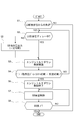
- FIG. 2 shows a flow of the lockup control process at start executed by the CVT control unit 12 of the first embodiment (startup lockup control means).
- startup lockup control means the CVT control unit 12 of the first embodiment
- step S ⁇ b> 1 it is determined whether or not the vehicle is starting due to an accelerator depression operation from a lockup release state in which the lockup clutch 3 is released. If YES (when starting), the process proceeds to step S2, and if NO (not starting), the process proceeds to the end.
- the vehicle is at the start by the accelerator depressing operation. For example, after confirming the selection operation to the traveling range and the brake release operation in the stopped state, the accelerator opening from the accelerator opening sensor 17 is 0 deg. Judge by being higher. The timer count is started when the accelerator is on (accelerator opening> 0 deg).
- step S2 following the determination in step S1 that the vehicle is starting, or the determination in step S4 that T ⁇ command pressure delay timer time + predetermined time, it is determined whether the lockup command pressure delay is in progress. Determine whether. If YES (during lockup command pressure delay), the process proceeds to step S3, and if NO (command pressure delay timer time has elapsed), the process proceeds to step S5.
- the determination that the lock-up command pressure delay is being performed is determined by the fact that the timer count time T that has been counted since the accelerator was turned on is equal to or less than the set command pressure delay timer time.
- This command pressure delay timer time is set based on a large number of experimental data as the time required for the line pressure to rise and stabilize after starting.
- the command pressure delay timer time may be given as a fixed time, or may be given as a variable time that varies depending on the transmission hydraulic oil temperature, which is an influence factor of the hydraulic response.
- step S3 following the determination that the lockup command pressure delay is being performed in step S2 or the lockup command pressure output in step S5, engine torque down control is performed, and the process proceeds to step S4.
- the target slip rotation speed characteristic of the lockup clutch 3 during the engine torque reduction control is set to a characteristic in which the target slip rotation speed from the start increases with a gentle gradient.
- step S4 following execution of the engine torque reduction control in step S3, it is determined whether or not the timer count time T exceeds the command pressure delay timer time + predetermined time. If YES (T> command pressure delay timer time + predetermined time), the process proceeds to step S6. If NO (T ⁇ command pressure delay timer time + predetermined time), the process returns to step S2.
- the predetermined time is set as a time required from the elapse of the command pressure delay timer time to the lockup capacity generation timing based on a large number of experimental data.
- step S5 following the determination that the command pressure delay timer time has elapsed in step S2, a lockup command pressure in a direction to engage the lockup clutch 3 is output, and the process returns to step S3.
- the lock-up command pressure from the time when the command pressure delay timer elapses until the end of the engine torque down control is given by the characteristic of gradually increasing with a constant gradient. That is, the lock-up capacity control of the lock-up clutch 3 is an open control that is performed with a predetermined ramp characteristic.
- step S6 following the determination that T> command pressure delay timer time + predetermined time in step S4, the engine torque down control is terminated, and the process proceeds to step S7.
- the engine torque down control is finished, the engine 1 returns to normal engine control with the fuel injection amount aiming at the engine torque corresponding to the driver requested driving force.
- step S7 following the determination that the engine torque down control has been completed in step S6 or that the lockup has not been completed in step S8, the lockup capacity control of the lockup clutch 3 is performed, and the process proceeds to step S8.
- the target slip rotation speed characteristic of the lockup clutch 3 after the end of the engine torque reduction control is set to a characteristic in which the target slip rotation speed from the end of the control decreases with a gentle gradient.
- the target lockup capacity when the actual slip rotation speed matches the target slip rotation speed, the target lockup capacity can be obtained by the difference between the engine torque and the converter capacity, as shown in FIG.
- ⁇ is a torque converter capacity coefficient
- Ne is an engine speed
- Ne ⁇ 2 is a square of the engine speed Ne.
- step S8 following the lockup capacity control in step S7, it is determined whether or not the engagement of the lockup clutch 3 has been completed. If YES (lockup complete), the process proceeds to the end. If NO (lockup complete), the process returns to step S7.
- the completion of engagement of the lockup clutch 3 is determined, for example, when the actual slip rotation speed becomes zero or a value near zero.
- the operation of the lockup clutch control device of the first embodiment is divided into “startup lockup control operation according to comparative example”, “startup lockup control processing operation”, and “startup lockup control operation according to first embodiment”. explain.
- time t1 is the accelerator depression time
- time t2 is the start time of engine torque and line pressure increase
- time t3 is the command pressure delay end time
- time t4 is the lockup capacity generation time
- time t5 is the lockup engagement. Completion time.
- the line pressure which is the original pressure of the actual lockup hydraulic pressure
- the line pressure increases as the actual engine speed increases. While the line pressure is rising, the line pressure is not stable, and the follow-up performance of the lock-up actual oil pressure to the lock-up command pressure is poor, so that a shock may occur. Therefore, the lockup command pressure is delayed while the line pressure is increasing.
- step S1 When starting the vehicle by depressing the accelerator from the lockup release state where the lockup clutch 3 is released, the process proceeds from step S1 to step S2 to step S3 to step S4 in the flowchart of FIG. While it is determined in step S4 that T ⁇ command pressure delay timer time + predetermined time, the flow from step S2 to step S3 to step S4 is repeated. That is, when starting, a lock-up command pressure delay is performed, and following the determination that the lock-up command pressure delay is being performed in step S2, engine torque down control is performed in step S3.
- the target slip rotational speed characteristic of the lockup clutch 3 during the torque down control is set to a characteristic in which the target slip rotational speed from the start increases with a gentle gradient. Then, the torque-down amount and the torque-down profile of the engine 1 are feedback-controlled so as to follow the target slip rotation speed characteristic in which the actual slip rotation speed is set.
- step S4 the command pressure delay timer time has elapsed, but while it is determined in step S4 that T ⁇ command pressure delay timer time + predetermined time, in the flowchart of FIG. 2, step S2 ⁇ step S5 ⁇ The flow from step S3 to step S4 is repeated. That is, while the command pressure delay is in progress, but the lockup capacity has not yet occurred, in step S5, the lockup command pressure with a constant gradient for engaging the lockup clutch 3 is output.
- step S4 After that, if it is determined in step S4 that T> command pressure delay timer time + predetermined time and the time condition is satisfied, the process proceeds from step S4 to step S6 ⁇ step S7 ⁇ step S8 in the flowchart of FIG. . Then, while it is determined in step S8 that lock-up is not completed, the flow from step S7 to step S8 is repeated. That is, when it is determined that the lockup capacity generation timing is reached due to the establishment of the time condition in step S4, the engine torque down control is terminated in step S6, and the lockup capacity control of the lockup clutch 3 is performed in the next step S7. Is implemented.
- the target slip rotation speed characteristic of the lockup clutch 3 after the end of the engine torque reduction control is set to a characteristic in which the target slip rotation speed from the end of the control decreases with a gentle gradient. Then, the target lockup command pressure to the lockup clutch 3 is feedback-controlled so as to follow the target slip rotation speed characteristic in which the actual slip rotation speed is set.
- time t1 is the accelerator depression time
- time t2 is the start time of engine torque and line pressure increase
- time t3 is the command pressure delay end time
- time t4 is the lockup capacity generation time
- time t5 is the lockup engagement. Completion time.
- the command pressure delay is in progress from the start time t1 to the command pressure delay end time t3, and no lockup capacity is generated during this time (lockup capacity ⁇ 0 Nm) .
- the target slip rotational speed characteristic of the lockup clutch 3 that is executing the engine torque reduction control increases with a gentle gradient from the start time. Set to the characteristic to be.
- engine torque down control (B in FIG. 5 is a torque down region with respect to the comparative example) is performed to suppress the rising gradient of the engine rotational speed so that the actual slip rotational speed follows the target slip rotational speed characteristics.
- the slip rotation speed of the lockup clutch 3 is controlled by engine torque down control.
- the engine torque is reduced by the engine torque reduction control, so that the engine 1 can be prevented from being blown up (C in FIG. 5 is an engine rotation shot-up suppression region for the comparative example).
- the target slip rotation speed characteristic of the lock-up clutch 3 after the end of the engine torque down control is a gentle gradient of the target slip rotation speed from the end of the control. Is set to the characteristic of descending. Then, the target lockup command pressure to the lockup clutch 3 is feedback-controlled so as to follow the target slip rotation speed characteristic in which the actual slip rotation speed is set. In other words, from the lockup capacity generation time t4 to the lockup engagement completion time t5, the slip rotation speed of the lockup clutch 3 is controlled by engine torque and lockup capacity control.
- the increase in the lockup command pressure is delayed while the line pressure that is the original pressure of the actual lockup hydraulic pressure is increasing. And at least during the delay of the lock-up command pressure, the torque of the engine 1 is reduced. That is, during the delay of the lock-up command pressure that does not generate the lock-up capacity, the torque of the engine 1 is reduced, so that the engine torque is reduced and the engine speed-up is suppressed. As a result, when the lock-up clutch 3 is fastened at the time of start, the engine 1 can be prevented from being blown up.
- the engine 1 is torque-down from the start until the lock-up clutch 3 generates a lock-up capacity. That is, when suppressing the engine speed increase by torque down, if the engine torque reduction is terminated early, the engine speed may not be sufficiently suppressed. On the other hand, if the engine torque reduction is ended late, the engine speed decrease gradient increases, and torque fluctuations may occur when returning to normal engine torque control. On the other hand, the lock-up clutch 3 generates a lock-up capacity, and the torque is reduced to an appropriate timing as a load for the engine 1. As described above, the engine torque reduction is performed until the lockup capacity is generated, so that the engine 1 can be reliably prevented from being swung up.
- the target slip rotation speed characteristic of the lockup clutch 3 during the engine torque reduction control is set to a characteristic in which the target slip rotation speed from the start increases with a gentle gradient. And it was set as the structure which controls the torque down amount and torque down profile of the engine 1 so that a real slip rotation speed may follow a target slip rotation speed characteristic (S3 of FIG. 2). That is, when the engine 1 is torque-down, if it is performed by open control that gives a predetermined torque-down amount, the engine speed may be excessively suppressed or the engine speed may be insufficiently suppressed.
- engine torque reduction control is performed using feedback control of slip rotation speed, which is the differential rotation speed between engine rotation speed and turbine rotation speed. For this reason, the engine speed increase characteristic with respect to the turbine rotation speed (vehicle speed equivalent) increase characteristic at the time of starting becomes the target characteristic defined in the target slip rotation speed characteristic, and the engine speed increase is suppressed.
- the target slip rotation speed characteristic of the lockup clutch 3 after the end of the engine torque reduction control is set to a characteristic in which the target slip rotation speed from the end of the control decreases with a gentle gradient.
- lockup capacity control is performed using feedback control of slip rotation speed, which is the difference rotation speed between the engine rotation speed and the turbine rotation speed. For this reason, the engine speed is controlled to converge to the turbine speed in accordance with the target slip speed characteristic, and both the prevention of lock-up fastening shock and the early completion of lock-up fastening are achieved.
- the engine torque reduction control is terminated when a time condition in which the timer count time T started from the start exceeds a time obtained by adding a predetermined time to the command pressure delay timer time is satisfied (see FIG. 2 S4 ⁇ S6). That is, the start-up lock-up control employs a command pressure delay until the line pressure is stabilized, and uses a timer that is counted from the start when the command pressure delay is performed. Therefore, by using an existing timer and giving the lock-up capacity generation timing according to the time condition, the lock-up capacity generation timing can be determined while having a simple configuration without adding an arithmetic configuration or the like.
- a start-up lockup control means (FIG. 2) is provided for delaying an increase in the lockup command pressure while the original pressure of the lockup actual hydraulic pressure is increasing.
- the start-up lockup control means (FIG. 2) performs torque reduction of the engine 1 at least during the delay of the lockup command pressure. For this reason, when the lock-up clutch 3 is fastened at the time of starting, it is possible to suppress the engine 1 from being swung up. In addition, fuel consumption can be improved by being able to fasten lock-up early.
- the start-up lockup control means reduces the torque of the engine 1 from the start until the lockup clutch 3 generates a lockup capacity. For this reason, in addition to the effect of (1), the torque is reduced to an appropriate timing, that is, the lockup capacity generation timing, so that it is possible to surely prevent the engine 1 from being swung up.
- the start-up lock-up control means (FIG. 2) is characterized in that the target slip rotational speed characteristic of the lock-up clutch 3 during engine torque reduction control is increased with a gentle gradient from the start. And the torque-down amount and torque-down profile of the engine 1 are controlled so that the actual slip rotational speed follows the target slip rotational speed characteristic (S3). For this reason, in addition to the effect of (1) or (2), during the engine torque reduction control, the engine speed can be increased by the target engine speed specified by the setting characteristic of the target slip speed. It is possible to suppress the rising of numbers.
- the start-up lock-up control means (FIG. 2) lowers the target slip rotation speed characteristic of the lock-up clutch 3 after the end of the engine torque down control with a gentle gradient from the end of the control.
- the target lockup command pressure to the lockup clutch 3 is controlled so that the actual slip rotation speed is in line with the target slip rotation speed characteristic (S7). For this reason, in addition to the effects of (1) to (3), after the engine torque down control is completed, the engine speed and turbine speed converge according to the target slip speed setting characteristics, thereby preventing lockup engagement shocks. And early completion of lockup fastening can be achieved.
- the start-up lock-up control means determines that the engine torque is reduced when the timer count time started from the start exceeds the indicated pressure delay timer time plus a predetermined time.
- the control is terminated (S4 ⁇ S6). Therefore, in addition to the effects (1) to (4), it is possible to determine the lockup capacity generation timing with a simple configuration using an existing timer used in the lockup command pressure delay control.
- Example 2 is an example in which the lockup capacity generation timing for ending the engine torque down control is determined based on the change speed condition.
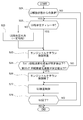
- FIG. 6 shows a flow of the lockup control process at start executed by the CVT control unit 12 of the second embodiment (startup lockup control means).
- start-up lockup control means the CVT control unit 12 of the second embodiment (startup lockup control means).
- steps S21 to S23 and steps S25 to S28 are the same steps as steps S1 to S3 and steps S5 to S8 in FIG.
- step S24 following execution of the engine torque reduction control in step S23, whether or not any change speed condition in which the engine speed change speed is equal to or higher than a predetermined value or the actual slip speed change speed is higher than a predetermined value is satisfied. Determine whether. If YES (change speed condition is satisfied), the process proceeds to step S26. If NO (change speed condition is not satisfied), the process returns to step S22.
- the engine speed changing speed is obtained by time-differentiating the engine speed from the engine speed sensor 14.
- the predetermined values of the engine speed change speed and the actual slip speed change speed are both changed from the positive value on the acceleration side to the negative value on the deceleration side before and after the lockup capacity generation timing, so that the difference between the two values Set. Since the system configuration is the same as that of the first embodiment, illustration and description thereof are omitted.
- the engine torque reduction control is terminated when a change speed condition in which the engine speed change speed or the actual slip speed change speed changes by a predetermined value or more is satisfied. That is, the engine speed increases until the lockup capacity is generated, so that the engine speed change speed becomes the acceleration side.
- the lockup capacity is generated, the engine 1 becomes a load and the engine speed decreases, so that the engine speed changing speed is shifted to the deceleration side. That is, as shown in the engine speed change speed characteristic of FIG. 5, the engine speed change speed is switched from a positive value on the acceleration side to a negative value on the deceleration side before and after time t4 which is the lockup capacity generation timing.
- the actual slip rotation speed change speed changes from a positive value on the acceleration side to a negative value on the deceleration side before and after time t4, which is the lockup capacity generation timing.
- the timing when the lockup capacity is actually generated can be accurately determined. Since other operations are the same as those of the first embodiment, description thereof is omitted.
- the start-up lock-up control means ends the engine torque reduction control when a change speed condition in which the engine speed change speed or the actual slip speed change speed changes by a predetermined value or more is satisfied (S24 ⁇ S26). For this reason, in addition to the effects (1) to (4), the timing at which the lockup capacity is actually generated can be accurately determined by using the engine speed change speed condition or the actual slip speed change speed condition. it can.
- the third embodiment is an example in which the lockup capacity generation timing for ending the engine torque down control is determined based on the lockup pressure condition.
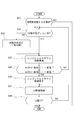
- FIG. 7 shows a flow of a lockup control process at start executed by the CVT control unit 12 of the third embodiment (startup lockup control means).
- start-up lockup control means the CVT control unit 12 of the third embodiment (startup lockup control means).
- steps S31 to S33 and steps S35 to S38 are the same steps as steps S1 to S3 and steps S5 to S8 in FIG.
- step S34 following the execution of engine torque reduction control in step S33, whether or not the lockup pressure condition that either the lockup command pressure exceeds a certain value or the actual lockup oil pressure exceeds a certain value is satisfied. Determine whether. If YES (lockup pressure condition is satisfied), the process proceeds to step S36, and if NO (lockup pressure condition is not satisfied), the process returns to step S32.
- the lockup command pressure is obtained by a calculation process in the CVT control unit 12.
- the actual lockup hydraulic pressure is obtained from the actual lockup hydraulic pressure sensor 20.
- the constant values of the lockup command pressure and the actual lockup hydraulic pressure are set according to a value of 0 Nm to several Nm because a lockup capacity is generated when 0 Nm or more. At this time, in consideration of response delay, a constant value of the lockup command pressure and a constant value of the actual lockup hydraulic pressure may be different from each other. Since the system configuration is the same as that of the first embodiment, illustration and description thereof are omitted.
- the engine torque down control is terminated when a lockup pressure condition in which the command pressure or the actual hydraulic pressure of the lockup clutch 3 exceeds a certain value is satisfied. That is, as shown in the lockup command pressure characteristic and the lockup actual hydraulic pressure characteristic of FIG. 5, at time t4 that is the lockup capacity generation timing, the lockup command pressure is slightly higher than 0 Nm and the lockup actual hydraulic pressure becomes 0 Nm. . Therefore, by using the lockup command pressure condition or the lockup actual hydraulic pressure condition, the generation start timing of the lockup capacity preceding the actual capacity generation is accurately determined. Since other operations are the same as those of the first embodiment, description thereof is omitted.
- the start-up lock-up control means ends the engine torque-down control when the lock-up pressure condition in which the command pressure or the actual hydraulic pressure of the lock-up clutch 3 exceeds a certain value is satisfied (S34 ⁇ S36). . Therefore, in addition to the effects (1) to (4), the lockup capacity generation start timing can be accurately determined by using the lockup command pressure condition or the lockup actual hydraulic pressure condition.
- start-up lockup control means a preferable example is shown in which the engine 1 is torque-down from the start until the lockup clutch 3 generates a lockup capacity.
- any start-up lockup control means may be used as long as the engine torque is reduced at least during the delay of the lockup command pressure.
- the engine torque may be reduced until the delay of the lockup command pressure is completed, and after the delay of the lockup command pressure is terminated, only for a predetermined time regardless of the timing of occurrence of the lockup capacity. It is good also as an example which extends and implements torque reduction of an engine.
- the engine torque down control a preferable example is shown in which the torque down amount and the torque down profile of the engine 1 are controlled so that the actual slip rotational speed follows the target slip rotational speed characteristics.
- the engine torque down control for example, the engine torque down amount and the torque down profile may be controlled by engine speed control that causes the actual engine speed to follow the target engine speed characteristics.
- the target lockup command pressure to the lockup clutch 3 is controlled so that the actual slip rotation speed conforms to the target slip rotation speed characteristics. showed that.
- the target lockup command pressure may be controlled by engine speed control that causes the actual engine speed to follow the target engine speed characteristics.
- Example 1 shows an example in which the lockup capacity generation timing is determined based on a time condition
- Example 2 shows an example in which the lockup capacity generation timing is determined based on a change speed condition.
- the means for determining the lockup capacity generation timing may be an example of combining the plurality of conditions and determining that it is the lockup capacity generation timing when any one of the plurality of conditions is satisfied.
- Embodiments 1 to 3 show examples in which the lockup clutch control device of the present invention is applied to an engine vehicle equipped with a continuously variable transmission.
- the lock-up clutch control device according to the present invention can be applied to a hybrid vehicle as long as the engine is mounted on a drive source, and a stepped automatic shift is performed as a transmission.
- a stepped transmission may be used.
- it can be applied to any vehicle provided with a torque converter having a lock-up clutch between the engine and the transmission.
Landscapes
- Engineering & Computer Science (AREA)
- General Engineering & Computer Science (AREA)
- Mechanical Engineering (AREA)
- Physics & Mathematics (AREA)
- Fluid Mechanics (AREA)
- Control Of Fluid Gearings (AREA)
- Control Of Driving Devices And Active Controlling Of Vehicle (AREA)
Abstract
Description
この車両において、発進時にロックアップクラッチを締結させる際、ロックアップ実油圧の元圧が上昇している間、ロックアップ指示圧の上昇をディレーさせる発進時ロックアップ制御手段を設ける。
発進時ロックアップ制御手段は、少なくともロックアップ指示圧のディレー中、エンジンのトルクダウンを実施する。
すなわち、ロックアップ容量が発生しないロックアップ指示圧のディレー中、エンジンのトルクダウンを実施することで、エンジントルクが低下し、エンジンの回転吹け上がりが抑えられる。
この結果、発進時、ロックアップクラッチを締結させる際、エンジンの回転吹け上がりを抑えることができる。
実施例1における車両のロックアップクラッチ制御装置の構成を、「全体システム構成」、「発進時ロックアップ制御構成」に分けて説明する。
図1は、実施例1のロックアップクラッチ制御装置が適用されたエンジン車を示す。以下、図1に基づき、全体システム構成を説明する。
図2は、実施例1のCVTコントロールユニット12にて実行される発進時ロックアップ制御処理の流れを示す(発進時ロックアップ制御手段)。以下、発進時ロックアップ制御処理構成をあらわす図2の各ステップについて説明する。なお、図2での「LU」という記述は、ロックアップの略称である。
ここで、アクセル踏み込み操作による発進時であるとの判断は、例えば、停車状態での走行レンジへのセレクト操作及びブレーキ足離し操作を確認した後、アクセル開度センサ17からのアクセル開度が0degより高くなったことで判断する。なお、アクセルオン(アクセル開度>0deg)からタイマカウントを開始する。
ここで、ロックアップ指示圧ディレー中であるとの判断は、アクセルオンからカウントが開始されたタイマカウント時間Tが、設定された指示圧ディレータイマ時間以下であることで判断される。この指示圧ディレータイマ時間は、発進後にライン圧が上昇し、かつ、安定するまでに要する時間として、多数の実験データに基づき設定される。また、指示圧ディレータイマ時間は、固定時間で与えても良いし、油圧応答の影響要因である変速機作動油温などによって異なる可変時間で与えても良い。
このエンジントルクダウン制御では、エンジントルクダウン制御実施中のロックアップクラッチ3の目標スリップ回転数特性を、発進時からの目標スリップ回転数が緩やかな勾配で上昇する特性に設定する。そして、実スリップ回転数(=エンジン回転数-タービン回転数)が目標スリップ回転数特性に沿うように、エンジン1のトルクダウン量とトルクダウンプロフィールをフィードバック制御する。
ここで、所定時間は、多数の実験データに基づき、指令圧ディレータイマ時間を経過してからロックアップ容量発生タイミングまでに要する時間として設定される。
ここで、指示圧ディレータイマ時間経過後からエンジントルクダウン制御終了までのロックアップ指示圧は、一定勾配により緩やかに上昇する特性にて与える。つまり、ロックアップクラッチ3のロックアップ容量制御を、予め決めたランプ特性で行うオープン制御とする。
ここで、エンジントルクダウン制御を終了すると、エンジン1は、ドライバー要求駆動力に応じたエンジントルクを目指す燃料噴射量による通常のエンジン制御に復帰する。
このロックアップ容量制御では、エンジントルクダウン制御終了後のロックアップクラッチ3の目標スリップ回転数特性を、制御終了時からの目標スリップ回転数が緩やかな勾配で下降する特性に設定する。そして、実スリップ回転数(=エンジン回転数-タービン回転数)が目標スリップ回転数特性に沿うように、ロックアップクラッチ3への目標ロックアップ指示圧をフィードバック制御する。
このロックアップ容量制御において、実スリップ回転数が目標スリップ回転数に一致した場合は、図3に示すように、エンジントルクとコンバータ容量の差により目標ロックアップ容量を得ることができる。なお、図3において、τはトルクコンバータ容量係数、Neはエンジン回転数、Ne^2はエンジン回転数Neの二乗をあらわす。
ここで、ロックアップクラッチ3の締結完了は、例えば、実スリップ回転数がゼロやゼロ近傍の値になったことで判断する。
実施例1のロックアップクラッチ制御装置における作用を、「比較例による発進時ロックアップ制御作用」、「発進時ロックアップ制御処理作用」、「実施例1による発進時ロックアップ制御作用」に分けて説明する。
以下、比較例による発進時ロックアップ制御作用を、図4に示すタイムチャートにより説明する。なお、図4において、時刻t1はアクセル踏み込み時刻、時刻t2はエンジントルク及びライン圧の上昇開始時刻、時刻t3は指示圧ディレー終了時刻、時刻t4はロックアップ容量発生時刻、時刻t5はロックアップ締結完了時刻である。
以下、実施例1の発進時ロックアップ制御処理作用を、図2に示すフローチャートに基づき説明する。
以下、実施例1による発進時ロックアップ制御作用を、図5に示すタイムチャートにより説明する。なお、図5において、時刻t1はアクセル踏み込み時刻、時刻t2はエンジントルク及びライン圧の上昇開始時刻、時刻t3は指示圧ディレー終了時刻、時刻t4はロックアップ容量発生時刻、時刻t5はロックアップ締結完了時刻である。
すなわち、ロックアップ容量が発生しないロックアップ指示圧のディレー中、エンジン1のトルクダウンを実施することで、エンジントルクが低下し、エンジンの回転吹け上がりが抑えられる。
この結果、発進時、ロックアップクラッチ3を締結させる際、エンジン1の回転吹け上がりを抑えることができる。
すなわち、エンジン1の回転吹け上がりをトルクダウンで抑える際、エンジントルクダウン実施を早期に終了させると、回転吹け上がりを十分に抑制ができないおそれがある。一方、エンジントルクダウン実施を遅く終了させると、エンジン回転数低下勾配が大きくなり、通常のエンジントルク制御へ復帰するときにトルク変動を生じるおそれがある。
これに対し、ロックアップクラッチ3がロックアップ容量を発生し、エンジン1にとって負荷となる適切なタイミングまでトルクダウンが実施される。このように、エンジントルクダウン実施をロックアップ容量発生までとすることで、エンジン1の回転吹け上がりが確実に抑えられる。
すなわち、エンジン1をトルクダウンするに際し、予め決めたトルクダウン量を与えるオープン制御により行うと、エンジン回転数を過剰に抑えたり、エンジン回転数の抑制が不足したりすることがある。
これに対し、エンジン回転数とタービン回転数の差回転数であるスリップ回転数のフィードバック制御を用いてエンジントルクダウン制御を行っている。このため、発進時におけるタービン回転数(車速相当)の上昇特性に対するエンジン回転数の上昇特性が、目標スリップ回転数特性に規定された狙いとする特性となり、エンジン回転数の吹け上がりが抑えられる。
すなわち、ロックアップ容量制御を行うに際し、予め決めた特性にてロックアップ指示圧を与えるオープン制御により行う場合、早期締結を目指し特性勾配を急勾配にするとロックアップ締結ショックが生じる。逆に、ショック防止を目指し特性勾配を緩勾配にするとロックアップ締結完了時期が遅れる。
これに対し、エンジン回転数とタービン回転数の差回転数であるスリップ回転数のフィードバック制御を用いてロックアップ容量制御を行っている。このため、目標スリップ回転数特性に沿ってエンジン回転数をタービン回転数に収束させる制御となり、ロックアップ締結ショック防止と、ロックアップ締結の早期完了と、の両立が図られる。
すなわち、発進時ロックアップ制御では、ライン圧が安定するまでの指示圧ディレーを採用し、指示圧ディレーを行う際に発進時からカウントされるタイマを用いている。
したがって、既存のタイマを利用し、ロックアップ容量発生タイミングを時間条件により与えることで、演算構成などの追加がない簡単な構成でありながらロックアップ容量発生タイミングが判断される。
実施例1のロックアップクラッチ制御装置にあっては、下記に列挙する効果が得られる。
発進時にロックアップクラッチ3を締結させる際、ロックアップ実油圧の元圧が上昇している間、ロックアップ指示圧の上昇をディレーさせる発進時ロックアップ制御手段(図2)を設け、
発進時ロックアップ制御手段(図2)は、少なくともロックアップ指示圧のディレー中、エンジン1のトルクダウンを実施する。
このため、発進時、ロックアップクラッチ3を締結させる際、エンジン1の回転吹け上がりを抑えることができる。加えて、早期にロックアップ締結できることによって、燃費を向上させることもできる。
このため、(1)の効果に加え、ロックアップ容量発生タイミングという適切なタイミングまでのトルクダウン実施になることで、エンジン1の回転吹け上がりを確実に抑えることができる。
このため、(1)又は(2)の効果に加え、エンジントルクダウン制御実施中、目標スリップ回転数の設定特性により規定されたエンジン回転数の狙いとする上昇特性が得られることで、エンジン回転数の吹け上がりを抑えることができる。
このため、(1)~(3)の効果に加え、エンジントルクダウン制御終了後、目標スリップ回転数の設定特性に沿ってエンジン回転数とタービン回転数が収束することで、ロックアップ締結ショック防止と、ロックアップ締結の早期完了と、の両立を図ることができる。
このため、(1)~(4)の効果に加え、ロックアップ指示圧ディレー制御で用いる既存のタイマを利用した簡単な構成でありながら、ロックアップ容量発生タイミングを判断することができる。
図6は、実施例2のCVTコントロールユニット12にて実行される発進時ロックアップ制御処理の流れを示す(発進時ロックアップ制御手段)。以下、発進時ロックアップ制御処理構成をあらわす図6の各ステップについて説明する。なお、ステップS21~ステップS23、ステップS25~ステップS28の各ステップは、図2のステップS1~ステップS3、ステップS5~ステップS8の各ステップと同じ処理を行うステップであるため説明を省略する。
ここで、エンジン回転数変化速度は、エンジン回転数センサ14からのエンジン回転数を時間微分処理することで得る。実スリップ回転数変化速度は、エンジン回転数センサ14からのエンジン回転数からタービン回転数センサ15からのタービン回転数の差(=実スリップ回転数)を求め、この実スリップ回転数を時間微分処理することで得る。エンジン回転数変化速度と実スリップ回転数変化速度の所定値は、いずれもロックアップ容量発生タイミングの前後で加速側の正値から減速側の負値に切り替わることで、2つの値の乖離幅により設定する。なお、システム構成は、実施例1と同様であるので図示並びに説明を省略する。
実施例2では、エンジン回転数変化速度又は実スリップ回転数変化速度が所定値以上変化する変化速度条件が成立すると、エンジントルクダウン制御を終了する構成とした。
すなわち、ロックアップ容量が発生するまでエンジン回転数が上昇することで、エンジン回転数変化速度は加速側となる。これに対し、ロックアップ容量が発生すると、エンジン1にとって負荷となりエンジン回転数が下降することで、エンジン回転数変化速度は減速側に転じる。つまり、図5のエンジン回転数変化速度特性に示すように、ロックアップ容量発生タイミングである時刻t4の前後で、エンジン回転数変化速度は加速側の正値から減速側の負値に切り替わる。同様に、図5の実スリップ回転数変化速度特性に示すように、ロックアップ容量発生タイミングである時刻t4の前後で、実スリップ回転数変化速度は加速側の正値から減速側の負値に切り替わる。
したがって、エンジン回転数変化速度条件又は実スリップ回転数変化速度条件を用いることで、実際にロックアップ容量が発生したタイミングが精度良く判断される。なお、他の作用は、実施例1と同様であるので、説明を省略する。
実施例2のロックアップクラッチ制御装置にあっては、下記の効果が得られる。
このため、(1)~(4)の効果に加え、エンジン回転数変化速度条件又は実スリップ回転数変化速度条件を用いることで、実際にロックアップ容量が発生したタイミングを精度良く判断することができる。
図7は、実施例3のCVTコントロールユニット12にて実行される発進時ロックアップ制御処理の流れを示す(発進時ロックアップ制御手段)。以下、発進時ロックアップ制御処理構成をあらわす図7の各ステップについて説明する。なお、ステップS31~ステップS33、ステップS35~ステップS38の各ステップは、図2のステップS1~ステップS3、ステップS5~ステップS8の各ステップと同じ処理を行うステップであるため説明を省略する。
ここで、ロックアップ指示圧は、CVTコントロールユニット12での演算処理により得る。ロックアップ実油圧は、ロックアップ実油圧センサ20から得る。ロックアップ指示圧とロックアップ実油圧の一定値は、0Nm以上になるとロックアップ容量が発生することで、0Nm~数Nmの値により設定する。このとき、応答遅れを考慮し、ロックアップ指示圧の一定値とロックアップ実油圧の一定値を異ならせた値としても良い。なお、システム構成は、実施例1と同様であるので図示並びに説明を省略する。
実施例3では、ロックアップクラッチ3の指示圧又は実油圧が一定値を超えるロックアップ圧条件が成立すると、エンジントルクダウン制御を終了する構成とした。
すなわち、図5のロックアップ指示圧特性及びロックアップ実油圧特性に示すように、ロックアップ容量発生タイミングである時刻t4では、ロックアップ指示圧が0Nmより少し高く、ロックアップ実油圧が0Nmになる。
したがって、ロックアップ指示圧条件又はロックアップ実油圧条件を用いることで、実際の容量発生に先行するロックアップ容量の発生開始タイミングが精度良く判断される。なお、他の作用は、実施例1と同様であるので、説明を省略する。
実施例3のロックアップクラッチ制御装置にあっては、下記の効果が得られる。
このため、(1)~(4)の効果に加え、ロックアップ指示圧条件又はロックアップ実油圧条件を用いることで、ロックアップ容量の発生開始タイミングを精度良く判断することができる。
Claims (7)
- ロックアップクラッチを有するトルクコンバータを、エンジンと変速機の間に備えた車両において、
発進時に前記ロックアップクラッチを締結させる際、ロックアップ実油圧の元圧が上昇している間、ロックアップ指示圧の上昇をディレーさせる発進時ロックアップ制御手段を設け、
前記発進時ロックアップ制御手段は、少なくともロックアップ指示圧のディレー中、前記エンジンのトルクダウンを実施する
ことを特徴とする車両のロックアップクラッチ制御装置。 - 請求項1に記載された車両のロックアップクラッチ制御装置において、
前記発進時ロックアップ制御手段は、発進時から前記ロックアップクラッチがロックアップ容量を発生するまで前記エンジンのトルクダウンを実施する
ことを特徴とする車両のロックアップクラッチ制御装置。 - 請求項1又は請求項2に記載された車両のロックアップクラッチ制御装置において、
前記発進時ロックアップ制御手段は、エンジントルクダウン制御実施中の前記ロックアップクラッチの目標スリップ回転数特性を、発進時からの目標スリップ回転数が緩やかな勾配で上昇する特性に設定し、実スリップ回転数が前記目標スリップ回転数特性に沿うように、前記エンジンのトルクダウン量とトルクダウンプロフィールを制御する
ことを特徴とする車両のロックアップクラッチ制御装置。 - 請求項1から請求項3までの何れか一項に記載された車両のロックアップクラッチ制御装置において、
前記発進時ロックアップ制御手段は、エンジントルクダウン制御終了後の前記ロックアップクラッチの目標スリップ回転数特性を、制御終了時からの目標スリップ回転数が緩やかな勾配で下降する特性に設定し、実スリップ回転数が前記目標スリップ回転数特性に沿うように、前記ロックアップクラッチへの目標ロックアップ指示圧を制御する
ことを特徴とする車両のロックアップクラッチ制御装置。 - 請求項1から請求項4までの何れか一項に記載された車両のロックアップクラッチ制御装置において、
前記発進時ロックアップ制御手段は、発進時からカウント開始されたタイマカウント時間が、指示圧ディレータイマ時間に所定時間を加えた時間を超える時間条件が成立すると、エンジントルクダウン制御を終了する
ことを特徴とする車両のロックアップクラッチ制御装置。 - 請求項1から請求項4までの何れか一項に記載された車両のロックアップクラッチ制御装置において、
前記発進時ロックアップ制御手段は、エンジン回転数変化速度又は実スリップ回転数変化速度が所定値以上変化する変化速度条件が成立すると、エンジントルクダウン制御を終了する
ことを特徴とする車両のロックアップクラッチ制御装置。 - 請求項1から請求項4までの何れか一項に記載された車両のロックアップクラッチ制御装置において、
前記発進時ロックアップ制御手段は、前記ロックアップクラッチの指示圧又は実油圧が一定値を超えるロックアップ圧条件が成立すると、エンジントルクダウン制御を終了する
ことを特徴とする車両のロックアップクラッチ制御装置。
Priority Applications (5)
| Application Number | Priority Date | Filing Date | Title |
|---|---|---|---|
| PCT/JP2014/072744 WO2016031050A1 (ja) | 2014-08-29 | 2014-08-29 | 車両のロックアップクラッチ制御装置 |
| EP14900725.4A EP3187744B1 (en) | 2014-08-29 | 2014-08-29 | Vehicle lockup clutch control device |
| CN201480081580.XA CN106605076B (zh) | 2014-08-29 | 2014-08-29 | 车辆的锁止离合器控制装置 |
| US15/327,168 US9920796B2 (en) | 2014-08-29 | 2014-08-29 | Vehicle lock-up clutch control device |
| JP2016545193A JP6288279B2 (ja) | 2014-08-29 | 2014-08-29 | 車両のロックアップクラッチ制御装置 |
Applications Claiming Priority (1)
| Application Number | Priority Date | Filing Date | Title |
|---|---|---|---|
| PCT/JP2014/072744 WO2016031050A1 (ja) | 2014-08-29 | 2014-08-29 | 車両のロックアップクラッチ制御装置 |
Publications (1)
| Publication Number | Publication Date |
|---|---|
| WO2016031050A1 true WO2016031050A1 (ja) | 2016-03-03 |
Family
ID=55398985
Family Applications (1)
| Application Number | Title | Priority Date | Filing Date |
|---|---|---|---|
| PCT/JP2014/072744 Ceased WO2016031050A1 (ja) | 2014-08-29 | 2014-08-29 | 車両のロックアップクラッチ制御装置 |
Country Status (5)
| Country | Link |
|---|---|
| US (1) | US9920796B2 (ja) |
| EP (1) | EP3187744B1 (ja) |
| JP (1) | JP6288279B2 (ja) |
| CN (1) | CN106605076B (ja) |
| WO (1) | WO2016031050A1 (ja) |
Cited By (1)
| Publication number | Priority date | Publication date | Assignee | Title |
|---|---|---|---|---|
| JP2017172628A (ja) * | 2016-03-22 | 2017-09-28 | トヨタ自動車株式会社 | ロックアップクラッチの制御装置 |
Families Citing this family (2)
| Publication number | Priority date | Publication date | Assignee | Title |
|---|---|---|---|---|
| CN109307065B (zh) * | 2017-07-26 | 2021-04-16 | 上海汽车集团股份有限公司 | 一种液力变矩器的锁止控制方法及装置 |
| JP7266018B2 (ja) * | 2020-11-20 | 2023-04-27 | 本田技研工業株式会社 | 制御装置 |
Citations (3)
| Publication number | Priority date | Publication date | Assignee | Title |
|---|---|---|---|---|
| JP2011202776A (ja) * | 2010-03-26 | 2011-10-13 | Toyota Motor Corp | 車両用ロックアップクラッチの制御装置 |
| WO2012095970A1 (ja) * | 2011-01-12 | 2012-07-19 | トヨタ自動車株式会社 | ハイブリッド車両の制御装置 |
| JP2013204766A (ja) * | 2012-03-29 | 2013-10-07 | Jatco Ltd | 車両の発進制御装置及び発進制御方法 |
Family Cites Families (8)
| Publication number | Priority date | Publication date | Assignee | Title |
|---|---|---|---|---|
| JPH05270297A (ja) * | 1992-03-27 | 1993-10-19 | Unisia Jecs Corp | 車両用自動変速機の制御装置 |
| US5314050A (en) * | 1992-12-09 | 1994-05-24 | Eaton Corporation | Clutch mode control logic |
| JPH0872590A (ja) * | 1994-09-02 | 1996-03-19 | Nissan Motor Co Ltd | エンジン・自動変速機の制御装置 |
| JP3031257B2 (ja) * | 1996-08-01 | 2000-04-10 | トヨタ自動車株式会社 | ロックアップクラッチのスリップ制御装置 |
| JP3239816B2 (ja) * | 1997-09-19 | 2001-12-17 | 日産自動車株式会社 | トルクコンバータのスリップ制御装置 |
| JP3915714B2 (ja) | 2003-02-28 | 2007-05-16 | マツダ株式会社 | 変速機の制御装置 |
| JP4072829B2 (ja) * | 2004-03-31 | 2008-04-09 | ジヤトコ株式会社 | 自動変速機の制御装置 |
| JP4731153B2 (ja) * | 2004-11-04 | 2011-07-20 | 日産自動車株式会社 | 自動変速機の制御装置 |
-
2014
- 2014-08-29 EP EP14900725.4A patent/EP3187744B1/en active Active
- 2014-08-29 JP JP2016545193A patent/JP6288279B2/ja active Active
- 2014-08-29 CN CN201480081580.XA patent/CN106605076B/zh active Active
- 2014-08-29 US US15/327,168 patent/US9920796B2/en active Active
- 2014-08-29 WO PCT/JP2014/072744 patent/WO2016031050A1/ja not_active Ceased
Patent Citations (3)
| Publication number | Priority date | Publication date | Assignee | Title |
|---|---|---|---|---|
| JP2011202776A (ja) * | 2010-03-26 | 2011-10-13 | Toyota Motor Corp | 車両用ロックアップクラッチの制御装置 |
| WO2012095970A1 (ja) * | 2011-01-12 | 2012-07-19 | トヨタ自動車株式会社 | ハイブリッド車両の制御装置 |
| JP2013204766A (ja) * | 2012-03-29 | 2013-10-07 | Jatco Ltd | 車両の発進制御装置及び発進制御方法 |
Non-Patent Citations (1)
| Title |
|---|
| See also references of EP3187744A4 * |
Cited By (1)
| Publication number | Priority date | Publication date | Assignee | Title |
|---|---|---|---|---|
| JP2017172628A (ja) * | 2016-03-22 | 2017-09-28 | トヨタ自動車株式会社 | ロックアップクラッチの制御装置 |
Also Published As
| Publication number | Publication date |
|---|---|
| US20170175828A1 (en) | 2017-06-22 |
| US9920796B2 (en) | 2018-03-20 |
| EP3187744A1 (en) | 2017-07-05 |
| JPWO2016031050A1 (ja) | 2017-04-27 |
| EP3187744B1 (en) | 2018-08-08 |
| CN106605076A (zh) | 2017-04-26 |
| EP3187744A4 (en) | 2017-10-25 |
| CN106605076B (zh) | 2018-07-03 |
| JP6288279B2 (ja) | 2018-03-07 |
Similar Documents
| Publication | Publication Date | Title |
|---|---|---|
| JP6268197B2 (ja) | 無段変速機の制御装置 | |
| JP6296163B2 (ja) | 車両のロックアップクラッチ制御装置 | |
| JP6637525B2 (ja) | 車両のロックアップ制御装置 | |
| JP6350668B2 (ja) | 車両のロックアップクラッチ制御装置 | |
| JP6372621B2 (ja) | 車両のロックアップ制御方法及び制御装置 | |
| EP3366953B1 (en) | Vehicular lock-up control method and control device | |
| WO2013073646A1 (ja) | 自動変速機の制御装置 | |
| US10443717B2 (en) | Control method and control device for transmission mechanism | |
| JP6288279B2 (ja) | 車両のロックアップクラッチ制御装置 | |
| WO2018074564A1 (ja) | 車両用無段変速機の制御装置および制御方法 | |
| JP5467973B2 (ja) | 車両の自動変速装置 | |
| JP5708185B2 (ja) | 車両制御装置 | |
| JP7118555B2 (ja) | 無段変速機の制御装置 | |
| JP2013117274A (ja) | 車両制御装置 | |
| JP6752506B2 (ja) | 車両用無段変速機構の制御装置 | |
| JP4484560B2 (ja) | 自動変速機の変速制御装置 | |
| EP3575582A1 (en) | Method for controlling vehicle and device for controlling vehicle | |
| JP2017082835A (ja) | 車両のロックアップ制御方法及び制御装置 | |
| JP2016048086A (ja) | 車両のロックアップクラッチ制御装置 |
Legal Events
| Date | Code | Title | Description |
|---|---|---|---|
| 121 | Ep: the epo has been informed by wipo that ep was designated in this application |
Ref document number: 14900725 Country of ref document: EP Kind code of ref document: A1 |
|
| ENP | Entry into the national phase |
Ref document number: 2016545193 Country of ref document: JP Kind code of ref document: A |
|
| WWE | Wipo information: entry into national phase |
Ref document number: 15327168 Country of ref document: US |
|
| NENP | Non-entry into the national phase |
Ref country code: DE |
|
| REEP | Request for entry into the european phase |
Ref document number: 2014900725 Country of ref document: EP |
|
| WWE | Wipo information: entry into national phase |
Ref document number: 2014900725 Country of ref document: EP |