WO2016031142A1 - 曲面形状を有する部材の研磨加工工具と加工方法 - Google Patents
曲面形状を有する部材の研磨加工工具と加工方法 Download PDFInfo
- Publication number
- WO2016031142A1 WO2016031142A1 PCT/JP2015/003853 JP2015003853W WO2016031142A1 WO 2016031142 A1 WO2016031142 A1 WO 2016031142A1 JP 2015003853 W JP2015003853 W JP 2015003853W WO 2016031142 A1 WO2016031142 A1 WO 2016031142A1
- Authority
- WO
- WIPO (PCT)
- Prior art keywords
- polishing
- resin layer
- groove
- hard resin
- polishing pad
- Prior art date
- Legal status (The legal status is an assumption and is not a legal conclusion. Google has not performed a legal analysis and makes no representation as to the accuracy of the status listed.)
- Ceased
Links
Images


Classifications
-
- B—PERFORMING OPERATIONS; TRANSPORTING
- B24—GRINDING; POLISHING
- B24B—MACHINES, DEVICES, OR PROCESSES FOR GRINDING OR POLISHING; DRESSING OR CONDITIONING OF ABRADING SURFACES; FEEDING OF GRINDING, POLISHING, OR LAPPING AGENTS
- B24B37/00—Lapping machines or devices; Accessories
- B24B37/11—Lapping tools
- B24B37/20—Lapping pads for working plane surfaces
- B24B37/22—Lapping pads for working plane surfaces characterised by a multi-layered structure
-
- B—PERFORMING OPERATIONS; TRANSPORTING
- B24—GRINDING; POLISHING
- B24B—MACHINES, DEVICES, OR PROCESSES FOR GRINDING OR POLISHING; DRESSING OR CONDITIONING OF ABRADING SURFACES; FEEDING OF GRINDING, POLISHING, OR LAPPING AGENTS
- B24B29/00—Machines or devices for polishing surfaces on work by means of tools made of soft or flexible material with or without the application of solid or liquid polishing agents
-
- B—PERFORMING OPERATIONS; TRANSPORTING
- B24—GRINDING; POLISHING
- B24B—MACHINES, DEVICES, OR PROCESSES FOR GRINDING OR POLISHING; DRESSING OR CONDITIONING OF ABRADING SURFACES; FEEDING OF GRINDING, POLISHING, OR LAPPING AGENTS
- B24B37/00—Lapping machines or devices; Accessories
-
- B—PERFORMING OPERATIONS; TRANSPORTING
- B24—GRINDING; POLISHING
- B24B—MACHINES, DEVICES, OR PROCESSES FOR GRINDING OR POLISHING; DRESSING OR CONDITIONING OF ABRADING SURFACES; FEEDING OF GRINDING, POLISHING, OR LAPPING AGENTS
- B24B37/00—Lapping machines or devices; Accessories
- B24B37/11—Lapping tools
- B24B37/20—Lapping pads for working plane surfaces
- B24B37/24—Lapping pads for working plane surfaces characterised by the composition or properties of the pad materials
- B24B37/245—Pads with fixed abrasives
-
- B—PERFORMING OPERATIONS; TRANSPORTING
- B24—GRINDING; POLISHING
- B24B—MACHINES, DEVICES, OR PROCESSES FOR GRINDING OR POLISHING; DRESSING OR CONDITIONING OF ABRADING SURFACES; FEEDING OF GRINDING, POLISHING, OR LAPPING AGENTS
- B24B37/00—Lapping machines or devices; Accessories
- B24B37/11—Lapping tools
- B24B37/20—Lapping pads for working plane surfaces
- B24B37/26—Lapping pads for working plane surfaces characterised by the shape of the lapping pad surface, e.g. grooved
-
- B—PERFORMING OPERATIONS; TRANSPORTING
- B24—GRINDING; POLISHING
- B24D—TOOLS FOR GRINDING, BUFFING OR SHARPENING
- B24D11/00—Constructional features of flexible abrasive materials; Special features in the manufacture of such materials
-
- B—PERFORMING OPERATIONS; TRANSPORTING
- B24—GRINDING; POLISHING
- B24B—MACHINES, DEVICES, OR PROCESSES FOR GRINDING OR POLISHING; DRESSING OR CONDITIONING OF ABRADING SURFACES; FEEDING OF GRINDING, POLISHING, OR LAPPING AGENTS
- B24B37/00—Lapping machines or devices; Accessories
- B24B37/11—Lapping tools
Definitions
- the present invention relates to a polishing method.
- a buffing process is known as a processing method for smoothing an object to be polished having a curved surface, for example, a resin coating surface of an automobile or the like (for example, Patent Document 1).
- the buffing process is a method in which a polishing object is polished by attaching various abrasives or the like to the periphery (surface) of a polishing wheel (buff) made of cloth or other material, and rotated.
- This invention makes it a subject to provide the grinding
- a polishing method polishes a resin-coated surface having a curved surface using a polishing pad having a polishing surface formed of a hard resin layer.
- the polished surface may follow the resin-coated surface.
- the polishing surface may be made to follow the resin coating surface.
- the polishing surface may be made to follow the resin coating surface by forming a groove on the polishing surface.
- the pressing force of the polishing surface against the resin coating surface may be made constant.
- the resin-coated surface may be polished using a second polishing pad having a hardness lower than that of the hard resin layer.
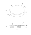
- FIG. 2A is a perspective view of a polishing pad according to an embodiment of the present invention
- FIG. 2B is a cross-sectional view taken along line AA of the polishing pad shown in FIG.
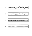
- (A) is explanatory drawing of the surface shape of the resin coating surface before grinding
- (b) is explanatory drawing of the surface shape of the resin coating surface after the buffing process which is a comparative example
- (c) is FIG. It is explanatory drawing of the surface shape of the resin coating surface after grinding
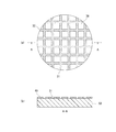
- (A) is a top view of a polishing pad according to a second embodiment of the present invention
- (b) is an AA cross-sectional view of the polishing pad shown in (a) of FIG. (A) is sectional drawing of the 1st modification of the polishing pad shown to (a) of FIG. 4,
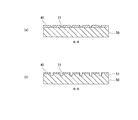
- (b) is sectional drawing of the 2nd modification of the polishing pad shown to (a) of FIG. (A) is a top view of a third modification of the polishing pad shown in (a) of FIG. 4, and (b) is a cross-sectional view taken along line AA of the polishing pad shown in (a) of FIG.
- a resin-coated surface having a curved surface is polished using a polishing pad having a polishing surface formed of a hard resin layer.
- the resin coating surface may be, for example, a coating surface of a vehicle body such as a vehicle.
- the polishing surface may follow the resin coating surface.
- polishing is performed by forming, on a polishing pad, a two-layer structure including a hard resin layer that forms a polishing surface and a soft resin layer that supports the hard resin layer. The surface may follow the resin coating surface.
- the polishing surface may be made to follow the resin coating surface by supporting a hard resin layer using an elastic member.
- the elastic member is distorted and the hard resin layer is bent according to the curved surface, so that the polishing surface follows the curved surface of the resin coating surface.
- the pressing force of the polishing surface against the resin coating surface may be made constant.
- the resin coating surface may be polished using a second polishing pad having a lower hardness than the hard resin layer.
- the polishing method according to the first embodiment attaches a polishing pad having a polishing surface formed of a hard resin layer to an automatic polishing apparatus having a robot arm, and polishes a resin coating surface having a curved surface.
- the automatic polishing apparatus 1 includes a robot arm 2, a polishing pad 10, a polishing tool 4, a pressing pressure detection unit 5, and a controller 7.
- Reference numeral 90 indicates an object to be polished.
- the object to be polished 90 may be a vehicle body such as an automobile whose surface is coated with resin.
- the robot arm 2 has a plurality of joints 20, 21, and 22, and can move a distal end portion 23 to which the polishing pad 10, the polishing tool 4, and the pressing pressure detection unit 5 are attached in a plurality of directions.
- the polishing tool 4 is attached to the tip portion 23 via the pressing pressure detection unit 5, and rotates the polishing pad 10 about a direction perpendicular to the polishing surface 30 by a built-in driving means.
- the controller 7 controls the behavior of the robot arm 2 and the rotation of the polishing pad 10 by the polishing tool 4.
- a polishing agent is supplied between the polishing pad 10 and the workpiece 90 from a polishing agent supply mechanism (not shown).
- the controller 7 polishes the surface of the workpiece 90 by pressing the polishing pad 10 against the surface of the workpiece 90 by the robot arm 2 and rotating the polishing pad 10.
- the pressing pressure detector 5 detects the pressing force of the polishing surface 30 against the workpiece 90.
- the controller 7 may adjust the force for pressing the polishing surface 30 against the workpiece 90 based on the detection result by the pressing pressure detection unit 5. Based on the detection result of the pressing pressure detection unit 5, the controller 7 keeps the pressing force of the polishing surface 30 against the object 90 to be fixed, and the robot arm moves the surface of the object 90 so that the polishing surface 30 moves. 2 may be controlled.
- the polishing method according to the first embodiment is not limited to the automatic polishing apparatus described above.
- the polishing method according to the first embodiment is used for a manual operation in which a polishing pad having a polishing surface formed of a hard resin layer is attached to the tip of a hand polisher and a resin coating surface having a curved surface is polished. Also good.
- the configuration of the polishing pad 10 is not particularly limited as long as it has a polishing surface formed of a hard resin layer.
- the polishing pad 10 may have a structure in which the polishing surface of the polishing pad 10 follows the resin coating surface.
- the structure for causing the polishing surface of the polishing pad 10 to follow the resin coating surface has, for example, a two-layer structure including a hard resin layer that forms the polishing surface and a soft resin layer that supports the hard resin layer. It may be.
- the hard resin layer that forms the polished surface is simply referred to as “hard resin layer”
- the soft resin layer that supports the hard resin layer is simply referred to as “soft resin layer”.
- a polishing pad 10 having a two-layer structure including a hard resin layer that forms a polishing surface and a soft resin layer that supports the hard resin layer A configuration example will be described. Reference is made to FIG. 2A and FIG.
- the polishing pad 10 has a two-layer structure including a hard resin layer 40 and a soft resin layer 50.
- the hard resin layer 40 forms the polishing surface 30 of the polishing pad 10.
- the soft resin layer 50 supports the hard resin layer 40 and is distorted according to the curved surface when the polishing surface 30 is pressed against the curved surface of the resin coating surface. For this reason, the hard resin layer 40 bends along the curved surface, and the polishing surface 30 follows the curved surface of the resin coating surface.
- the hardness of the hard resin layer 40 is preferably 50 degrees or more, more preferably 60 degrees or more in terms of A hardness according to JIS K 6253.
- the hardness of the hard resin layer 40 is preferably 95 degrees or less.
- the hardness of the hard resin layer 40 is preferably 60 degrees or more and 80 degrees or less, or the hardness of the hard resin layer 40 is preferably 85 degrees or more and 95 degrees or less. If it is such a range, it will become difficult to polish the curved surface of the resin coating surface by the polishing pad 10, and it becomes possible to remove the waviness of the surface of the resin coating surface.
- the thickness of the hard resin layer 40 is not particularly limited, but is preferably 3.0 mm or less. Moreover, it is preferable that the thickness of the hard resin layer 40 is 0.5 mm or more. In such a range, when the polishing surface 30 is pressed against the curved surface of the resin coating surface, the hard resin layer 40 is easily bent along the curved surface of the resin coating surface, and the polishing surface against the curved surface of the object to be polished The followability of 30 is improved. For this reason, the waviness component of the surface shape of the object to be polished can be removed, and the contact area between the polishing surface 30 and the curved surface is increased to improve the polishing efficiency.
- the material of the hard resin layer 40 is not particularly limited as long as the material has the above hardness.
- the material of the hard resin layer 40 may be, for example, a polyurethane foam or a nonwoven fabric.
- the material of the hard resin layer 40 may be, for example, a nonwoven fabric having an A hardness of 60 degrees to 80 degrees, and may be a polyurethane foam having an A hardness of 85 degrees to 95 degrees.
- the hardness of the soft resin layer 50 is 30 degrees or less in E hardness according to JISK6253. If it is such a range, when the grinding
- the thickness of the soft resin layer 50 is not particularly limited, but is preferably 5.0 mm or more. Moreover, it is preferable that the thickness of the soft resin layer 50 is 50 mm or less. If it is such a range, when the grinding
- the material of the soft resin layer 50 is not particularly limited as long as the material has the above hardness.
- the material of the soft resin layer 50 may be, for example, a resin foam such as a polyurethane foam or a polyethylene foam.
- the abrasive is selected from particles made of oxides of silicon or metal elements such as silica, alumina, ceria, titania, zirconia, iron oxide and manganese oxide, organic particles made of thermoplastic resin, or organic-inorganic composite particles.
- a slurry containing abrasive grains can be used.
- the abrasive it is preferable to use an alumina slurry that enables a high polishing rate and is easily available.
- Alumina includes those having different crystal forms such as ⁇ -alumina, ⁇ -alumina, ⁇ -alumina, and ⁇ -alumina, and an aluminum compound called hydrated alumina also exists. From the viewpoint of the polishing rate, those containing ⁇ -alumina as the main component are more preferred as the abrasive grains.
- the average particle diameter of the abrasive grains is preferably 0.1 ⁇ m or more, more preferably 0.3 ⁇ m or more. As the average particle size increases, the polishing rate improves. When the average particle diameter is within the above range, it becomes easy to improve the polishing rate to a particularly suitable level for practical use. Moreover, it is preferable that an average particle diameter is 10.0 micrometers or less, More preferably, it is 5.0 micrometers or less. As the average particle size decreases, the dispersion stability of the abrasive improves, and the generation of scratches on the polished surface is suppressed.
- the average particle size of the abrasive grains can be measured by a pore electrical resistance method (measuring instrument: Multisizer III type, manufactured by Beckman Coulter, Inc.).
- the content of abrasive grains in the abrasive is preferably 0.1% by mass or more, more preferably 0.2% by mass or more, and further preferably 0.5% by mass or more. As the abrasive grain content increases, the polishing rate increases.
- the content of the abrasive grains is within the above range, it becomes easy to improve the polishing rate to a particularly suitable level for practical use. Moreover, it is preferable that content of an abrasive grain is 50 mass% or less, More preferably, it is 25 mass% or less, More preferably, it is 20 mass%.
- content of the abrasive grains is within the above range, the cost of the abrasive can be suppressed. Moreover, it can suppress more that a surface defect arises on the surface of the grinding
- the abrasive may appropriately contain other components such as a lubricating oil, an organic solvent, a surfactant, and a thickener as necessary in addition to the abrasive grains.
- the lubricating oil may be a synthetic oil, mineral oil, vegetable oil or combination thereof.
- the organic solvent may be alcohol, ether, glycols, glycerin or the like in addition to the hydrocarbon solvent.
- the surfactant may be a so-called anion, cation, nonion, or amphoteric surfactant.
- the thickener may be a synthetic thickener, a cellulose thickener, or a natural thickener.
- a resin-coated surface is polished using a polishing pad having a polishing surface formed of a hard resin layer. For this reason, compared with a soft polished surface, polishing of the resin coating surface is difficult and polishing is difficult. As a result, the undulation component of the surface shape of the resin coated surface can be removed.
- the polishing method of the first embodiment uses the polishing pad 10 having a structure in which the polishing surface 30 follows the curved surface of the resin coating surface.
- the polishing surface 30 follows the curved surface of the resin coating surface, the waviness component of the surface shape of the object to be polished can be removed, and the contact area of the polishing surface 30 that contacts the resin coating surface having a curved surface increases. By doing so, the polishing efficiency is improved, and the time required for polishing a relatively large resin coated surface can be shortened.
- FIG. 3A schematically shows the profile of the surface shape of the resin-coated surface before polishing.
- the surface shape before polishing has a surface roughness component having a relatively high frequency and a swell component having a relatively low frequency.
- FIG. 3B shows a profile of the surface shape of the resin coated surface after buffing as a comparative example. In the buffing process, the hardness of the polishing cloth is relatively low, resulting in a level polishing. For this reason, the surface roughness component is removed, but the waviness component remains after polishing.
- FIG. 3C schematically shows a profile of the surface shape of the resin-coated surface after polishing with the polishing pad 10 of the first embodiment. Since the polishing surface 30 is formed by the hard resin layer 40, the surface of the resin coating surface is not easily polished and is difficult to be polished. For this reason, the undulation component of the surface shape of the resin coating surface is removed.
- polishing may be performed.
- the polishing pad attached to the polishing tool 4 shown in FIG. 1 is replaced, and a polishing pad having a hardness lower than that of the hard resin layer 40 of the polishing pad 10 is used.
- the surface of the object 90 is polished.
- the hardness of the polishing pad used for secondary polishing is, for example, preferably less than 50 degrees in terms of A hardness, and more preferably 40 degrees or less.
- the hardness of the polishing pad used for secondary polishing is preferably 30 degrees or more. Within such a range, it becomes possible to remove fine surface roughness components on the surface of the resin coating surface.
- FIG. 3D schematically shows a profile of the surface shape of the resin-coated surface after the secondary polishing. By polishing with the polishing pad 10 and subsequent secondary polishing, both the surface roughness and the undulation of the surface of the resin coating surface are removed.
- the material of the polishing pad used for the secondary polishing is not particularly limited as long as the material has the above hardness.
- the material of the polishing pad used for secondary polishing may be, for example, a nonwoven fabric or suede.
- the material of the polishing pad used for the secondary polishing may be suede having an A hardness of 30 degrees to 40 degrees.
- the polishing pad used for the secondary polishing may have a two-layer structure like the polishing pad 10. That is, the polishing pad used for secondary polishing may have a two-layer structure including a relatively hard first layer that forms a polishing surface and a relatively soft second layer that supports the first layer. .
- the hardness of the first layer is preferably lower than the hardness of the hard resin layer 40 of the polishing pad 10.
- the hardness of the first layer is preferably less than 50 degrees in terms of A hardness, and more preferably 40 degrees or less.
- the hardness of the first layer is preferably 30 degrees or more.
- the thickness of the first layer is preferably 3.0 mm or less. Also, the thickness of the first layer is preferably 0.5 mm or more. In such a range, when the polished surface is pressed against the curved surface of the resin-coated surface, the first layer is easily bent along the curved surface of the resin-coated surface, and the contact area between the polished surface and the curved surface increases. Polishing efficiency is improved.
- the material of the first layer is not particularly limited as long as the material has the above hardness.
- the material of the first layer may be a non-woven fabric or suede, for example.
- the material of the first layer may be suede having an A hardness of 30 degrees or more and 40 degrees or less.
- the configuration of the second layer may be the same as the configuration of the soft resin layer 50 of the polishing pad 10.
- the structure of the polishing pad 10 is not limited to the two-layer structure shown in FIG. 2A and FIG.
- the polishing pad 10 only needs to include a hard resin layer that forms the polishing surface 30.
- the polishing pad 10 may not include a soft resin layer for supporting a hard resin layer that forms the polishing surface 30.
- the controller 7 shown in FIG. 1 may control the robot arm 2 so that the polishing surface 30 moves along the curved surface of the surface of the workpiece 90. By controlling the robot arm 2 so that the polishing surface 30 moves along the curved surface of the surface of the workpiece 90, the undulation of the surface of the workpiece 90 is caused by the polishing surface 30 formed of a hard resin layer. Can be removed.
- the polishing surface is made to follow the resin coating surface by using a polishing pad having a groove formed on the polishing surface as the polishing pad 10 shown in FIG.
- a groove is not particularly limited.
- a portion of the resin layer that becomes a groove is removed by etching or the like.
- it can be formed by scanning the surface while pressing a circular cutting blade rotating at high speed against a predetermined amount of pad.
- FIGS. 4A and 4B Constituent elements having the same functions as those in FIG.
- a first groove 31 and a second groove 32 are formed on the polishing surface 30 of the polishing pad 10.
- the first groove 31 extends along a first direction on the polishing surface 30, and the second groove 32 extends along a second direction on the polishing surface 30 orthogonal to the first direction.
- the grooves are formed on the polishing surface 30 in a lattice shape.
- the depth of the first groove 31 and the second groove 32 may be the same as the thickness of the hard resin layer 40. That is, the hard resin layer 40 may be divided into a plurality by the first groove 31 and the second groove 32.
- the first groove 31 and the second groove 32 are formed only in the hard resin layer 40 and are not formed in the soft resin layer 50. Since the hard resin layer 40 is divided by the first groove 31 and the second groove 32, when the polishing surface 30 is pressed against the curved surface of the resin coating surface, the hard resin layer 40 is formed according to the curved surface. It becomes possible to displace in the contact direction. For this reason, it becomes easy for the polishing surface 30 to follow the curved surface of the resin coating surface.
- channel 32 is 0.5 mm or more, for example. Moreover, it is preferable that the groove width of the 1st groove
- channel 32 are 5.0 mm or more, for example. Moreover, it is preferable that the pitch of the 1st groove
- the depth of the first groove 31 and the second groove 32 may be shallower than the thickness of the hard resin layer 40. That is, the hard resin layer 40 is not divided into a plurality of parts by the first groove 31 and the second groove 32, and the thickness of the hard resin layer 40 in the first groove 31 and the second groove 32 is the other part. Thinner than the thickness. Since the rigidity of the first groove 31 and the second groove 32 is reduced, the hard resin layer 40 is easily bent. For this reason, it becomes easy for the polishing surface 30 to follow the curved surface of the resin coating surface.
- the depth of the first groove 31 and the second groove 32 may be deeper than the thickness of the hard resin layer 40. That is, the first groove 31 and the second groove 32 may be formed in the hard resin layer 40 and the soft resin layer 50. Therefore, the support surface 51 of the soft resin layer 50 that supports the hard resin layer 40 is also divided by the first groove 31 and the second groove 32. The divided hard resin layers 40 are respectively supported by the divided support surfaces 51.
- the rigidity of the soft resin layer 50 is reduced, and the polished surface 30 is pressed against the curved surface of the resin coating surface.
- the soft resin layer 50 is easily distorted according to the curved surface.
- the support surface 51 that supports the hard resin layer 40 is divided, the binding force between the support surfaces 51 is reduced, and the divided hard resin layers 40 are easily displaced independently. . For this reason, the amount of displacement of the hard resin layer 50 in the contact direction increases, and the polished surface 30 easily follows the curved surface of the resin-coated surface.
- the third modification reference is made to FIG. 6A and FIG.
- the polishing surface 30 only the first groove 31 is formed, and the second groove 32 is not formed.
- the grooves are formed in a stripe shape on the polishing surface 30.
- the depth of the first groove 31 may be deeper than the thickness of the hard resin layer 40. That is, the first groove 31 may be formed in the hard resin layer 40 and the soft resin layer 50. Therefore, the support surface 51 of the soft resin layer 50 that supports the hard resin layer 40 is also divided by the first groove 31.
- the divided hard resin layers 40 are respectively supported by the divided support surfaces 51.
- channel 31 may be the same as that of the hard resin layer 40, or may be shallow.
- the strength of the polishing surface can be improved, and the number of steps for forming the groove can be reduced, contributing to cost reduction.
- the first groove 31 in the hard resin layer 40 a decrease in followability of the polishing surface 30 due to the absence of the second groove 32 extending in the second direction is reduced.
- a groove may also be formed on the polishing surface of the polishing pad used for secondary polishing in the same manner as the polishing pad 10 according to the second embodiment.
- Example A polishing pad is formed by laminating a 1.5 mm thick polyurethane foam material and a hard resin layer having an A hardness of 90, and a 30.0 mm thick polyurethane resin material and a soft resin layer having an E hardness of 20 layers. After forming, the resin coating surface was polished. On the hard resin layer, a grid-shaped groove having a width of 2.0 mm, a pitch of 20.0 mm, and a depth of 3.0 mm is pressed against a pad by a predetermined amount of a circular cutting blade that rotates at a high speed after forming a two-layer structure. It was formed by scanning the surface. Moreover, an alumina slurry was used as the abrasive.
Landscapes
- Engineering & Computer Science (AREA)
- Mechanical Engineering (AREA)
- Finish Polishing, Edge Sharpening, And Grinding By Specific Grinding Devices (AREA)
- Polishing Bodies And Polishing Tools (AREA)
Abstract
曲面を有する樹脂塗装面のうねりを取り除くことが可能な研磨方法を提供する。硬質の樹脂層(40)で形成される研磨面(30)を有する研磨パッド(10)を用いて、曲面を有する樹脂塗装面を研磨する。
Description
本発明は、研磨方法に関する。
曲面を有する被研磨物、例えば自動車等の樹脂塗装面を平滑化する加工方法として、バフ研磨加工が知られている(例えば特許文献1)。バフ研磨加工は、布製またはその他の材料で作られた研磨輪(バフ)の周囲(表面)に種々の研磨剤などを付けて回転させ、研磨対象物を研磨する方法である。
しかしながら、バフ研磨加工では樹脂塗装面のうねりを取り除くことができず、美しい表面仕上げを実現することが難しかった。
本発明は、曲面を有する樹脂塗装面のうねりを取り除くことが可能な研磨方法を提供することを課題とする。
本発明は、曲面を有する樹脂塗装面のうねりを取り除くことが可能な研磨方法を提供することを課題とする。
前記課題を解決するため、本発明の一態様に係る研磨方法は、硬質の樹脂層で形成される研磨面を有する研磨パッドを用いて、曲面を有する樹脂塗装面を研磨する。
上記研磨方法において、研磨面を樹脂塗装面に追従させてもよい。硬質の樹脂層を支持する軟質の樹脂層と、硬質の樹脂層と、を含む2層構造を研磨パッドに形成することにより、研磨面を樹脂塗装面に追従させてもよい。
上記研磨方法において、研磨面に溝を形成することにより、研磨面を樹脂塗装面に追従させてもよい。
上記研磨方法において、研磨面を樹脂塗装面に追従させてもよい。硬質の樹脂層を支持する軟質の樹脂層と、硬質の樹脂層と、を含む2層構造を研磨パッドに形成することにより、研磨面を樹脂塗装面に追従させてもよい。
上記研磨方法において、研磨面に溝を形成することにより、研磨面を樹脂塗装面に追従させてもよい。
また、樹脂塗装面に対する研磨面の押圧力は一定にされてもよい。
上記研磨パッドによる研磨の後に、上記硬質の樹脂層より硬度が低い第2の研磨パッドを用いて樹脂塗装面を研磨してもよい。
また、上記の研磨方法においてアルミナ砥粒を含むスラリーを研磨剤として使用してもよい。
上記研磨パッドによる研磨の後に、上記硬質の樹脂層より硬度が低い第2の研磨パッドを用いて樹脂塗装面を研磨してもよい。
また、上記の研磨方法においてアルミナ砥粒を含むスラリーを研磨剤として使用してもよい。
本発明によれば、曲面を有する樹脂塗装面のうねりを取り除くことが可能な研磨方法を実現することができる。
本発明の目的及び利点は、特許請求の範囲に示した要素及びその組合せを用いて具現化され達成される。前述の一般的な記述及び以下の詳細な記述の両方は、単なる例示及び説明であり、特許請求の範囲のように本発明を限定するものでないと解するべきである。
以下、本発明の実施形態について図面を参照しながら詳細に説明する。
1.第1実施形態
第1実施形態に係る研磨方法では、硬質の樹脂層で形成される研磨面を有する研磨パッドを用いて、曲面を有する樹脂塗装面を研磨する。樹脂塗装面は、例えば、車両等の車体の塗装面であってよい。
第1実施形態に係る研磨方法において、例えば、研磨面を樹脂塗装面に追従させてもよい。
第1実施形態に係る研磨方法において、研磨面を形成する硬質の樹脂層と、この硬質の樹脂層を支持する軟質の樹脂層と、を含む2層構造を研磨パッドに形成することにより、研磨面を樹脂塗装面に追従させてもよい。研磨面が樹脂塗装面の曲面に押し当てられた場合に、曲面に応じて軟質の樹脂層が歪むことによって硬質の樹脂層が撓み、研磨面が樹脂塗装面の曲面に追従する。
1.第1実施形態
第1実施形態に係る研磨方法では、硬質の樹脂層で形成される研磨面を有する研磨パッドを用いて、曲面を有する樹脂塗装面を研磨する。樹脂塗装面は、例えば、車両等の車体の塗装面であってよい。
第1実施形態に係る研磨方法において、例えば、研磨面を樹脂塗装面に追従させてもよい。
第1実施形態に係る研磨方法において、研磨面を形成する硬質の樹脂層と、この硬質の樹脂層を支持する軟質の樹脂層と、を含む2層構造を研磨パッドに形成することにより、研磨面を樹脂塗装面に追従させてもよい。研磨面が樹脂塗装面の曲面に押し当てられた場合に、曲面に応じて軟質の樹脂層が歪むことによって硬質の樹脂層が撓み、研磨面が樹脂塗装面の曲面に追従する。
また、第1実施形態に係る研磨方法において、弾性部材を用いて硬質の樹脂層を支持することにより、研磨面を樹脂塗装面に追従させてもよい。研磨面が樹脂塗装面の曲面に押し当てられた場合に、弾性部材が歪んで硬質の樹脂層が曲面に応じて撓むことにより、研磨面が樹脂塗装面の曲面に追従する。
また、樹脂塗装面に対する研磨面の押圧力は一定にされてもよい。
また、硬質の樹脂層で形成された研磨面を有する研磨パッドによる研磨の後に、硬質の樹脂層より硬度が低い第2の研磨パッドを用いて樹脂塗装面を研磨してもよい。
また、研磨の際にアルミナ砥粒を含むスラリーを研磨剤として使用してもよい。
また、樹脂塗装面に対する研磨面の押圧力は一定にされてもよい。
また、硬質の樹脂層で形成された研磨面を有する研磨パッドによる研磨の後に、硬質の樹脂層より硬度が低い第2の研磨パッドを用いて樹脂塗装面を研磨してもよい。
また、研磨の際にアルミナ砥粒を含むスラリーを研磨剤として使用してもよい。
以下、第1実施形態を詳細に説明する。
1-1.研磨方法について
第1実施形態に係る研磨方法は、例えば、硬質の樹脂層で形成される研磨面を有する研磨パッドをロボットアームを備える自動研磨装置に取り付けて、曲面を有する樹脂塗装面を研磨する自動研磨処理に使用することができる。
図1を参照する。自動研磨装置1は、ロボットアーム2と、研磨パッド10と、研磨工具4と、押付圧検出部5と、コントローラ7を備える。参照符号90は、被研磨物を示す。被研磨物90は、例えば、表面が樹脂塗装された自動車等の車体であってよい。ロボットアーム2は、複数の関節20、21及び22を有し、研磨パッド10、研磨工具4及び押付圧検出部5が取り付けられた先端部23を複数方向に移動させることができる。
1-1.研磨方法について
第1実施形態に係る研磨方法は、例えば、硬質の樹脂層で形成される研磨面を有する研磨パッドをロボットアームを備える自動研磨装置に取り付けて、曲面を有する樹脂塗装面を研磨する自動研磨処理に使用することができる。
図1を参照する。自動研磨装置1は、ロボットアーム2と、研磨パッド10と、研磨工具4と、押付圧検出部5と、コントローラ7を備える。参照符号90は、被研磨物を示す。被研磨物90は、例えば、表面が樹脂塗装された自動車等の車体であってよい。ロボットアーム2は、複数の関節20、21及び22を有し、研磨パッド10、研磨工具4及び押付圧検出部5が取り付けられた先端部23を複数方向に移動させることができる。
研磨工具4は、押付圧検出部5を介して先端部23に取り付けられ、内蔵する駆動手段により研磨面30に垂直な方向を回転軸として研磨パッド10を回転させる。コントローラ7は、ロボットアーム2の挙動と、研磨工具4による研磨パッド10の回転を制御する。図示しない研磨剤供給機構からは、研磨パッド10と被研磨物90との間に研磨剤が供給される。コントローラ7は、ロボットアーム2によって研磨パッド10を被研磨物90の表面に押付けて研磨パッド10を回転させることによって、被研磨物90の表面を研磨する。押付圧検出部5は、被研磨物90に対する研磨面30の押圧力を検出する。コントローラ7は、押付圧検出部5による検出結果に基づいて研磨面30を被研磨物90に押し付ける力の調整を行ってもよい。コントローラ7は、押付圧検出部5による検出結果に基づいて、被研磨物90に対する研磨面30の押圧力を一定にしたまま、被研磨物90の表面を研磨面30が移動するようにロボットアーム2を制御してもよい。
また、第1実施形態に係る研磨方法は、上記の自動研磨装置に限定して使用されるものではない。例えば、第1実施形態に係る研磨方法は、硬質の樹脂層で形成される研磨面を有する研磨パッドをハンドポリッシャの先端に取り付けて、曲面を有する樹脂塗装面を研磨する手作業に使用されてもよい。
また、第1実施形態に係る研磨方法は、上記の自動研磨装置に限定して使用されるものではない。例えば、第1実施形態に係る研磨方法は、硬質の樹脂層で形成される研磨面を有する研磨パッドをハンドポリッシャの先端に取り付けて、曲面を有する樹脂塗装面を研磨する手作業に使用されてもよい。
研磨パッド10は、硬質の樹脂層で形成される研磨面を有しているものであれば特にその構成は限定されない。例えば、研磨パッド10は、研磨パッド10の研磨面を樹脂塗装面に追従させる構造を備えていてもよい。研磨パッド10の研磨面を樹脂塗装面に追従させる構造は、例えば、研磨面を形成する硬質の樹脂層と、この硬質の樹脂層を支持する軟質の樹脂層とを含む2層構造を有していてもよい。以下の説明では、研磨面を形成する硬質の樹脂層を単に「硬質の樹脂層」と表記し、硬質の樹脂層を支持する軟質の樹脂層を単に「軟質の樹脂層」と表記する。
1-2.研磨パッドの構成例について
以下、研磨パッド10の一例として、研磨面を形成する硬質の樹脂層と、この硬質の樹脂層を支持する軟質の樹脂層とを含む2層構造を有する研磨パッド10の構成例を説明する。図2の(a)及び図2の(b)を参照する。研磨パッド10は、硬質の樹脂層40と、軟質の樹脂層50とを含む2層構造を有する。硬質の樹脂層40は、研磨パッド10の研磨面30を形成する。軟質の樹脂層50は、硬質の樹脂層40を支持し、かつ研磨面30が樹脂塗装面の曲面に押し当てられた場合に曲面に応じて歪む。このため、硬質の樹脂層40が曲面に沿って撓み、研磨面30が樹脂塗装面の曲面に追従する。
以下、研磨パッド10の一例として、研磨面を形成する硬質の樹脂層と、この硬質の樹脂層を支持する軟質の樹脂層とを含む2層構造を有する研磨パッド10の構成例を説明する。図2の(a)及び図2の(b)を参照する。研磨パッド10は、硬質の樹脂層40と、軟質の樹脂層50とを含む2層構造を有する。硬質の樹脂層40は、研磨パッド10の研磨面30を形成する。軟質の樹脂層50は、硬質の樹脂層40を支持し、かつ研磨面30が樹脂塗装面の曲面に押し当てられた場合に曲面に応じて歪む。このため、硬質の樹脂層40が曲面に沿って撓み、研磨面30が樹脂塗装面の曲面に追従する。
1-3.硬質の樹脂層について
硬質の樹脂層40の硬度は、JIS K 6253に準じたA硬度で50度以上であることが好ましく、60度以上であることがより好ましい。また、硬質の樹脂層40の硬度は、95度以下であることが好ましい。例えば、硬質の樹脂層40の硬度は、60度以上80度以下であることが好ましく、又は硬質の樹脂層40の硬度は、85度以上95度以下であることが好ましい。このような範囲であれば、研磨パッド10による樹脂塗装面の曲面の研磨がならい研磨になりにくくなり、樹脂塗装面の表面のうねりを取り除くことが可能になる。
硬質の樹脂層40の硬度は、JIS K 6253に準じたA硬度で50度以上であることが好ましく、60度以上であることがより好ましい。また、硬質の樹脂層40の硬度は、95度以下であることが好ましい。例えば、硬質の樹脂層40の硬度は、60度以上80度以下であることが好ましく、又は硬質の樹脂層40の硬度は、85度以上95度以下であることが好ましい。このような範囲であれば、研磨パッド10による樹脂塗装面の曲面の研磨がならい研磨になりにくくなり、樹脂塗装面の表面のうねりを取り除くことが可能になる。
硬質の樹脂層40の厚さは、特に限定されるものではないが3.0mm以下であることが好ましい。また、硬質の樹脂層40の厚さは0.5mm以上であることが好ましい。このような範囲であれば、研磨面30が樹脂塗装面の曲面に押し当てられた場合に硬質の樹脂層40が樹脂塗装面の曲面に沿って撓みやすくなり、被研磨物の曲面に対する研磨面30の追従性が向上する。このため、被研磨物の表面形状のうねり成分を取り除くことができ、かつ研磨面30と曲面との接触面積が増えて研磨効率が向上する。
硬質の樹脂層40の材質は特に限定されず、上記の硬度を有する材質であればよい。特に、硬質の樹脂層40の材質は、例えば、ポリウレタン発泡体又は不織布であってよい。硬質の樹脂層40の材質は、例えば、A硬度が60度以上80度以下の不織布であってもよく、A硬度が85度以上95度以下のポリウレタン発泡体であってもよい。
硬質の樹脂層40の材質は特に限定されず、上記の硬度を有する材質であればよい。特に、硬質の樹脂層40の材質は、例えば、ポリウレタン発泡体又は不織布であってよい。硬質の樹脂層40の材質は、例えば、A硬度が60度以上80度以下の不織布であってもよく、A硬度が85度以上95度以下のポリウレタン発泡体であってもよい。
1-4.軟質の樹脂層について
軟質の樹脂層50の硬度は、JIS K 6253に準じたE硬度で30度以下であることが好ましい。このような範囲であれば、研磨面30が樹脂塗装面の曲面に押し当てられた場合に軟質の樹脂層50が歪みやすくなる。この結果、硬質の樹脂層40が樹脂塗装面の曲面に沿って撓みやすくなり、被研磨物の曲面に対する研磨面30の追従性が向上する。このため、被研磨物の表面形状のうねり成分を取り除くことができ、かつ研磨面30と曲面との接触面積が増えて研磨効率が向上する。
軟質の樹脂層50の硬度は、JIS K 6253に準じたE硬度で30度以下であることが好ましい。このような範囲であれば、研磨面30が樹脂塗装面の曲面に押し当てられた場合に軟質の樹脂層50が歪みやすくなる。この結果、硬質の樹脂層40が樹脂塗装面の曲面に沿って撓みやすくなり、被研磨物の曲面に対する研磨面30の追従性が向上する。このため、被研磨物の表面形状のうねり成分を取り除くことができ、かつ研磨面30と曲面との接触面積が増えて研磨効率が向上する。
軟質の樹脂層50の厚さは、特に限定されるものではないが5.0mm以上であることが好ましい。また、軟質の樹脂層50の厚さは、50mm以下であることが好ましい。このような範囲であれば、研磨面30が樹脂塗装面の曲面に押し当てられた場合に、軟質の樹脂層50の歪み量と硬質の樹脂層40の撓み量を確保することができる。
軟質の樹脂層50の材質は、材質は特に限定されず、上記の硬度を有する材質であればよい。軟質の樹脂層50の材質は、例えば、ポリウレタン発泡体又はポリエチレン発泡体等の樹脂発泡体であってよい。
軟質の樹脂層50の材質は、材質は特に限定されず、上記の硬度を有する材質であればよい。軟質の樹脂層50の材質は、例えば、ポリウレタン発泡体又はポリエチレン発泡体等の樹脂発泡体であってよい。
1-5.研磨剤について
上記の研磨方法において使用される研磨剤の例について説明する。
研磨剤としては、シリカ、アルミナ、セリア、チタニア、ジルコニア、酸化鉄及び酸化マンガン等のケイ素または金属元素の酸化物からなる粒子や、熱可塑性樹脂からなる有機粒子、又は有機無機複合粒子などから選ばれる砥粒を含むスラリーを用いることができる。
例えば研磨剤には、高研磨速度を可能にし、且つ容易に入手が可能であるアルミナスラリーを用いることが好ましい。
アルミナには、α-アルミナ、β-アルミナ、γ-アルミナ、θ-アルミナなどの結晶形態が異なるものがあり、また水和アルミナと呼ばれるアルミニウム化合物も存在する。研磨速度の観点からは、α-アルミナを主成分とするものが砥粒としてより好ましい。
上記の研磨方法において使用される研磨剤の例について説明する。
研磨剤としては、シリカ、アルミナ、セリア、チタニア、ジルコニア、酸化鉄及び酸化マンガン等のケイ素または金属元素の酸化物からなる粒子や、熱可塑性樹脂からなる有機粒子、又は有機無機複合粒子などから選ばれる砥粒を含むスラリーを用いることができる。
例えば研磨剤には、高研磨速度を可能にし、且つ容易に入手が可能であるアルミナスラリーを用いることが好ましい。
アルミナには、α-アルミナ、β-アルミナ、γ-アルミナ、θ-アルミナなどの結晶形態が異なるものがあり、また水和アルミナと呼ばれるアルミニウム化合物も存在する。研磨速度の観点からは、α-アルミナを主成分とするものが砥粒としてより好ましい。
砥粒の平均粒子径は0.1μm以上であることが好ましく、より好ましくは0.3μm以上である。平均粒子径が大きくなるにつれて、研磨速度は向上する。平均粒子径が上記の範囲内にある場合、研磨速度を実用上特に好適なレベルにまで向上させることが容易となる。
また、平均粒子径は、10.0μm以下であることが好ましく、より好ましくは5.0μm以下である。平均粒子径が小さくなるにつれて、研磨剤の分散安定性は向上し、研磨面のスクラッチ発生が抑制される。
また、平均粒子径は、10.0μm以下であることが好ましく、より好ましくは5.0μm以下である。平均粒子径が小さくなるにつれて、研磨剤の分散安定性は向上し、研磨面のスクラッチ発生が抑制される。
平均粒子径が上記の範囲内にある場合、研磨剤の分散安定性と、研磨面の表面精度を実用上特に好適なレベルにまで向上させることが容易となる。なお、砥粒の平均粒子径は、細孔電気抵抗法(測定機:マルチサイザーIII型 ベックマン・コールター社製)により測定することができる。
研磨剤中の砥粒の含有量は、好ましくは0.1質量%以上であり、より好ましくは0.2質量%以上であり、さらに好ましくは0.5質量%以上である。砥粒の含有量が多くなるにつれて、研磨速度は向上する。砥粒の含有量が上記の範囲内にある場合、研磨速度を実用上特に好適なレベルにまで向上させることが容易となる。
また、砥粒の含有量は、50質量%以下であることが好ましく、より好ましくは25質量%以下であり、さらに好ましくは20質量%である。砥粒の含有量が上記の範囲内にある場合、研磨剤のコストを抑えることができる。また、研磨剤を用いて研磨した後の研磨対象物の表面に表面欠陥が生じることをより抑えることができる。
研磨剤中の砥粒の含有量は、好ましくは0.1質量%以上であり、より好ましくは0.2質量%以上であり、さらに好ましくは0.5質量%以上である。砥粒の含有量が多くなるにつれて、研磨速度は向上する。砥粒の含有量が上記の範囲内にある場合、研磨速度を実用上特に好適なレベルにまで向上させることが容易となる。
また、砥粒の含有量は、50質量%以下であることが好ましく、より好ましくは25質量%以下であり、さらに好ましくは20質量%である。砥粒の含有量が上記の範囲内にある場合、研磨剤のコストを抑えることができる。また、研磨剤を用いて研磨した後の研磨対象物の表面に表面欠陥が生じることをより抑えることができる。
研磨剤は、上記砥粒の他、必要に応じて潤滑油、有機溶剤、界面活性剤、増粘材などの他の成分を適宜含んでもよい。
潤滑油は、合成油、鉱物油、植物性油脂又はそれらの組み合わせであってよい。
有機溶剤は、炭化水素系溶剤の他、アルコール、エーテル、グリコール類やグリセリン等であってよい。
界面活性剤は、いわゆるアニオン、カチオン、ノニオン、両性界面活性剤であってよい。
増粘材は、合成系増粘材、セルロース系増粘材、又は天然系増粘材であってよい。
潤滑油は、合成油、鉱物油、植物性油脂又はそれらの組み合わせであってよい。
有機溶剤は、炭化水素系溶剤の他、アルコール、エーテル、グリコール類やグリセリン等であってよい。
界面活性剤は、いわゆるアニオン、カチオン、ノニオン、両性界面活性剤であってよい。
増粘材は、合成系増粘材、セルロース系増粘材、又は天然系増粘材であってよい。
1-6.第1実施形態の効果について
第1実施形態の研磨方法は、硬質の樹脂層で形成される研磨面を有する研磨パッドを用いて樹脂塗装面を研磨する。このため、軟質の研磨面と比べて、樹脂塗装面の研磨がならい研磨になりにくい。この結果、樹脂塗装面の表面形状のうねり成分を取り除くことができる。
また、第1実施形態の研磨方法は、研磨面30を樹脂塗装面の曲面に追従させる構造を備える研磨パッド10を使用する。このため、研磨面30が樹脂塗装面の曲面に追従するので、被研磨物の表面形状のうねり成分を取り除くことができ、かつ曲面を有する樹脂塗装面に接触する研磨面30の接触面積が増加することにより研磨効率が向上し、比較的大きな樹脂塗装面の研磨に要する時間を短縮することができる。
第1実施形態の研磨方法は、硬質の樹脂層で形成される研磨面を有する研磨パッドを用いて樹脂塗装面を研磨する。このため、軟質の研磨面と比べて、樹脂塗装面の研磨がならい研磨になりにくい。この結果、樹脂塗装面の表面形状のうねり成分を取り除くことができる。
また、第1実施形態の研磨方法は、研磨面30を樹脂塗装面の曲面に追従させる構造を備える研磨パッド10を使用する。このため、研磨面30が樹脂塗装面の曲面に追従するので、被研磨物の表面形状のうねり成分を取り除くことができ、かつ曲面を有する樹脂塗装面に接触する研磨面30の接触面積が増加することにより研磨効率が向上し、比較的大きな樹脂塗装面の研磨に要する時間を短縮することができる。
図3の(a)~図3の(c)を参照する。図3の(a)は、研磨前の樹脂塗装面の表面形状のプロファイルを模式的に示す。研磨前の表面形状は、比較的周波数が高い表面粗さ成分と比較的周波数が低いうねり成分とを有している。
図3の(b)は、バフ研磨加工後の樹脂塗装面の表面形状のプロファイルを比較例として示す。バフ研磨加工では研磨布の硬度が比較的低く、ならい研磨になってしまう。このため、表面粗さ成分は取り除かれるが、うねり成分は研磨後も残る。
図3の(c)は、第1実施形態の研磨パッド10による研磨後の樹脂塗装面の表面形状のプロファイルを模式的に示す。硬質の樹脂層40によって研磨面30が形成されるので、樹脂塗装面の表面の研磨がならい研磨になりにくい。このため、樹脂塗装面の表面形状のうねり成分が取り除かれる。
図3の(b)は、バフ研磨加工後の樹脂塗装面の表面形状のプロファイルを比較例として示す。バフ研磨加工では研磨布の硬度が比較的低く、ならい研磨になってしまう。このため、表面粗さ成分は取り除かれるが、うねり成分は研磨後も残る。
図3の(c)は、第1実施形態の研磨パッド10による研磨後の樹脂塗装面の表面形状のプロファイルを模式的に示す。硬質の樹脂層40によって研磨面30が形成されるので、樹脂塗装面の表面の研磨がならい研磨になりにくい。このため、樹脂塗装面の表面形状のうねり成分が取り除かれる。
1-7.2次研磨について
なお、研磨パッド10による研磨の後に、微細な表面粗さ成分を取り除く場合には、研磨パッド10による1次研磨の後に、表面粗さ成分を取り除くための2次研磨を行ってもよい。この場合には、研磨パッド10による研磨の後に、例えば図1に示す研磨工具4に取り付けられた研磨パッドを交換し、研磨パッド10の硬質の樹脂層40よりも低い硬度を有する研磨パッドを用いて被研磨物90の表面を研磨する。
なお、研磨パッド10による研磨の後に、微細な表面粗さ成分を取り除く場合には、研磨パッド10による1次研磨の後に、表面粗さ成分を取り除くための2次研磨を行ってもよい。この場合には、研磨パッド10による研磨の後に、例えば図1に示す研磨工具4に取り付けられた研磨パッドを交換し、研磨パッド10の硬質の樹脂層40よりも低い硬度を有する研磨パッドを用いて被研磨物90の表面を研磨する。
2次研磨に用いる研磨パッドの硬度は、例えば、A硬度で50度未満であることが好ましく、40度以下であることがより好ましい。また、2次研磨に用いる研磨パッドの硬度は、30度以上であることが好ましい。このような範囲であれば、樹脂塗装面の表面の細かい表面粗さ成分を取り除くことが可能になる。
図3の(d)は、2次研磨後の樹脂塗装面の表面形状のプロファイルを模式的に示す。研磨パッド10による研磨とそれに続く2次研磨により、樹脂塗装面の表面の表面粗さとうねりの両方が取り除かれる。
図3の(d)は、2次研磨後の樹脂塗装面の表面形状のプロファイルを模式的に示す。研磨パッド10による研磨とそれに続く2次研磨により、樹脂塗装面の表面の表面粗さとうねりの両方が取り除かれる。
2次研磨に用いる研磨パッドの材質は特に限定されず、上記の硬度を有する材質であればよい。2次研磨に用いる研磨パッドの材質は、例えば、不織布又はスウェードであってよい。例えば、2次研磨に用いる研磨パッドの材質は、A硬度が30度以上40度以下のスウェードであってよい。
2次研磨に用いる研磨パッドは、研磨パッド10と同様に2層構造を有していてもよい。すなわち、2次研磨に用いる研磨パッドは、研磨面を形成する比較的硬質な第1層と、第1層を支持する比較的軟質な第2層を含む2層構造を有していてもよい。
2次研磨に用いる研磨パッドは、研磨パッド10と同様に2層構造を有していてもよい。すなわち、2次研磨に用いる研磨パッドは、研磨面を形成する比較的硬質な第1層と、第1層を支持する比較的軟質な第2層を含む2層構造を有していてもよい。
第1層の硬度は、研磨パッド10の硬質の樹脂層40の硬度よりも低いことが好ましい。第1層の硬度は、例えば、A硬度で50度未満であることが好ましく、40度以下であることがより好ましい。また、第1層の硬度は、30度以上であることが好ましい。
第1層の厚さは、3.0mm以下であることが好ましい。また、第1層の厚さは0.5mm以上であることが好ましい。このような範囲であれば、研磨面が樹脂塗装面の曲面に押し当てられた場合に第1層が樹脂塗装面の曲面に沿って撓みやすくなり、研磨面と曲面との接触面積が増えて研磨効率が向上する。
第1層の材質は特に限定されず、上記の硬度を有する材質であればよい。第1層の材質は、例えば、不織布又はスウェードであってよい。例えば、第1層の材質は、A硬度が30度以上40度以下のスウェードであってよい。
第2層の構成は、研磨パッド10の軟質の樹脂層50の構成と同様であってよい。
第1層の厚さは、3.0mm以下であることが好ましい。また、第1層の厚さは0.5mm以上であることが好ましい。このような範囲であれば、研磨面が樹脂塗装面の曲面に押し当てられた場合に第1層が樹脂塗装面の曲面に沿って撓みやすくなり、研磨面と曲面との接触面積が増えて研磨効率が向上する。
第1層の材質は特に限定されず、上記の硬度を有する材質であればよい。第1層の材質は、例えば、不織布又はスウェードであってよい。例えば、第1層の材質は、A硬度が30度以上40度以下のスウェードであってよい。
第2層の構成は、研磨パッド10の軟質の樹脂層50の構成と同様であってよい。
1-8.変形例
研磨パッド10の構造は、図2の(a)及び図2の(b)に示した2層構造に限られない。研磨パッド10は、研磨面30を形成する硬質の樹脂層を備えていればよい。例えば、研磨パッド10は、研磨面30を形成する硬質の樹脂層を支持するための軟質の樹脂層を備えなくてもよい。
この場合に、図1に示されるコントローラ7は、被研磨物90の表面の曲面に沿って研磨面30が移動するようにロボットアーム2を制御してもよい。被研磨物90の表面の曲面に沿って研磨面30が移動するようにロボットアーム2が制御されることによって、被研磨物90の表面のうねりを硬質の樹脂層で形成された研磨面30で取り除くことができる。
研磨パッド10の構造は、図2の(a)及び図2の(b)に示した2層構造に限られない。研磨パッド10は、研磨面30を形成する硬質の樹脂層を備えていればよい。例えば、研磨パッド10は、研磨面30を形成する硬質の樹脂層を支持するための軟質の樹脂層を備えなくてもよい。
この場合に、図1に示されるコントローラ7は、被研磨物90の表面の曲面に沿って研磨面30が移動するようにロボットアーム2を制御してもよい。被研磨物90の表面の曲面に沿って研磨面30が移動するようにロボットアーム2が制御されることによって、被研磨物90の表面のうねりを硬質の樹脂層で形成された研磨面30で取り除くことができる。
2.第2実施形態
続いて、本発明の第2実施形態について説明する。第2実施形態に係る研磨方法では、図1に示す研磨パッド10として研磨面に溝が形成された研磨パッドを使用することによって、研磨面を樹脂塗装面に追従させる。研磨面に溝が形成されることによって、研磨面が樹脂塗装面の曲面に押し当てられた場合に研磨面が樹脂塗装面の曲面に追従しやすくなる。
このような溝は、特に限定されるものではないが、例えば、硬質の樹脂層及び軟質の樹脂層を含む2層構造を形成した後に、エッチング等によって溝となる部分の樹脂層を取り除くことによって形成することができる。また、2層構造を形成した後に、高速回転する円形の切刃を所定量パッドに押し当てながら表面を走査することによって形成することができる。
続いて、本発明の第2実施形態について説明する。第2実施形態に係る研磨方法では、図1に示す研磨パッド10として研磨面に溝が形成された研磨パッドを使用することによって、研磨面を樹脂塗装面に追従させる。研磨面に溝が形成されることによって、研磨面が樹脂塗装面の曲面に押し当てられた場合に研磨面が樹脂塗装面の曲面に追従しやすくなる。
このような溝は、特に限定されるものではないが、例えば、硬質の樹脂層及び軟質の樹脂層を含む2層構造を形成した後に、エッチング等によって溝となる部分の樹脂層を取り除くことによって形成することができる。また、2層構造を形成した後に、高速回転する円形の切刃を所定量パッドに押し当てながら表面を走査することによって形成することができる。
2-1.溝の形態
図4の(a)及び図4の(b)を参照する。図2の(a)と同じ機能を有する構成要素には同一の符号を付してある。研磨パッド10の研磨面30には、第1溝31及び第2溝32が形成されている。第1溝31は、研磨面30上の第1方向に沿って延び、第2溝32は、第1方向に直交する研磨面30上の第2方向に沿って延びる。研磨面30に複数の第1溝31及び複数の第2溝32を形成することにより、研磨面30には溝が格子状に形成される。
図4の(a)及び図4の(b)を参照する。図2の(a)と同じ機能を有する構成要素には同一の符号を付してある。研磨パッド10の研磨面30には、第1溝31及び第2溝32が形成されている。第1溝31は、研磨面30上の第1方向に沿って延び、第2溝32は、第1方向に直交する研磨面30上の第2方向に沿って延びる。研磨面30に複数の第1溝31及び複数の第2溝32を形成することにより、研磨面30には溝が格子状に形成される。
第1溝31及び第2溝32の深さは、硬質の樹脂層40の厚さと同じであってよい。すなわち、第1溝31及び第2溝32によって硬質の樹脂層40は複数に分割されてよい。また、第1溝31及び第2溝32は硬質の樹脂層40のみに形成され、軟質の樹脂層50には形成されない。硬質の樹脂層40が第1溝31及び第2溝32により分割されていることにより、研磨面30が樹脂塗装面の曲面に押し当てられた場合に、曲面に応じて硬質の樹脂層40が当接方向に変位することが可能になる。このため、研磨面30が樹脂塗装面の曲面に追従しやすくなる。
第1溝31及び第2溝32の溝幅は、例えば0.5mm以上であることが好ましい。また、第1溝31及び第2溝32の溝幅は、例えば5.0mm以下であることが好ましい。
このような範囲であれば、溝の形成による研磨面30と樹脂塗装面との接触面積の減少を抑えながら、研磨面30が樹脂塗装面の曲面に押し当てられた場合の硬質の樹脂層40の変位量を確保し研磨面30を撓みやすくすることができる。
このような範囲であれば、溝の形成による研磨面30と樹脂塗装面との接触面積の減少を抑えながら、研磨面30が樹脂塗装面の曲面に押し当てられた場合の硬質の樹脂層40の変位量を確保し研磨面30を撓みやすくすることができる。
第1溝31のピッチ及び第2溝32のピッチは、例えば5.0mm以上であることが好ましい。また、第1溝31のピッチ及び第2溝32のピッチは、例えば50mm以下であることが好ましい。
このような範囲であれば、溝の形成による研磨面30と樹脂塗装面との接触面積の減少を抑えながら、研磨面30が樹脂塗装面の曲面に押し当てられた場合の研磨面30の全体のたわみ量を確保することができる。
これらの溝幅及びピッチの寸法は、以下に説明する第1~第3変形例でも同じである。
このような範囲であれば、溝の形成による研磨面30と樹脂塗装面との接触面積の減少を抑えながら、研磨面30が樹脂塗装面の曲面に押し当てられた場合の研磨面30の全体のたわみ量を確保することができる。
これらの溝幅及びピッチの寸法は、以下に説明する第1~第3変形例でも同じである。
2-2.第1変形例について
図5の(a)を参照する。第1溝31及び第2溝32の深さは、硬質の樹脂層40の厚さよりも浅くてもよい。すなわち、第1溝31及び第2溝32によって硬質の樹脂層40は複数に分割されておらず、第1溝31及び第2溝32の部分の硬質の樹脂層40の厚さが他の部分の厚さよりも薄い。第1溝31及び第2溝32の部分の剛性が低下するので、硬質の樹脂層40が撓みやすくなる。このため、研磨面30が樹脂塗装面の曲面に追従しやすくなる。
図5の(a)を参照する。第1溝31及び第2溝32の深さは、硬質の樹脂層40の厚さよりも浅くてもよい。すなわち、第1溝31及び第2溝32によって硬質の樹脂層40は複数に分割されておらず、第1溝31及び第2溝32の部分の硬質の樹脂層40の厚さが他の部分の厚さよりも薄い。第1溝31及び第2溝32の部分の剛性が低下するので、硬質の樹脂層40が撓みやすくなる。このため、研磨面30が樹脂塗装面の曲面に追従しやすくなる。
2-3.第2変形例について
図5の(b)を参照する。第1溝31及び第2溝32の深さは、硬質の樹脂層40の厚さよりも深くてもよい。すなわち、第1溝31及び第2溝32は、硬質の樹脂層40及び軟質の樹脂層50に形成されていてもよい。したがって、硬質の樹脂層40を支持する軟質の樹脂層50の支持面51も第1溝31及び第2溝32によって分割される。分割された複数の硬質の樹脂層40は、分割された複数の支持面51によってそれぞれ支持される。
図5の(b)を参照する。第1溝31及び第2溝32の深さは、硬質の樹脂層40の厚さよりも深くてもよい。すなわち、第1溝31及び第2溝32は、硬質の樹脂層40及び軟質の樹脂層50に形成されていてもよい。したがって、硬質の樹脂層40を支持する軟質の樹脂層50の支持面51も第1溝31及び第2溝32によって分割される。分割された複数の硬質の樹脂層40は、分割された複数の支持面51によってそれぞれ支持される。
第1溝31及び第2溝32が軟質の樹脂層50にも形成されているので、軟質の樹脂層50の剛性が低下し、研磨面30が樹脂塗装面の曲面に押し当てられた場合に、曲面に応じて軟質の樹脂層50が歪みやすくなる。また、硬質の樹脂層40を支持する支持面51が分割されていることにより、支持面51間の拘束力が低下して、分割された硬質の樹脂層40同士が独立して変位しやすくなる。このため、当接方向における硬質の樹脂層50の変位量が大きくなり、研磨面30が樹脂塗装面の曲面に追従しやすくなる。
2-4.第3変形例について
図6の(a)及び図6の(b)を参照する。研磨面30には、第1溝31のみが形成され、第2溝32が形成されていない。研磨面30に複数の第1溝31を形成することにより、研磨面30には溝がストライプ状に形成される。
第1溝31の深さは、硬質の樹脂層40の厚さよりも深くてもよい。すなわち、第1溝31は、硬質の樹脂層40及び軟質の樹脂層50に形成されていてもよい。したがって、硬質の樹脂層40を支持する軟質の樹脂層50の支持面51も第1溝31によって分割される。分割された複数の硬質の樹脂層40は、分割された複数の支持面51によってそれぞれ支持される。なお、第1溝31の深さは、硬質の樹脂層40の厚さと同じでも浅くてもよい。
図6の(a)及び図6の(b)を参照する。研磨面30には、第1溝31のみが形成され、第2溝32が形成されていない。研磨面30に複数の第1溝31を形成することにより、研磨面30には溝がストライプ状に形成される。
第1溝31の深さは、硬質の樹脂層40の厚さよりも深くてもよい。すなわち、第1溝31は、硬質の樹脂層40及び軟質の樹脂層50に形成されていてもよい。したがって、硬質の樹脂層40を支持する軟質の樹脂層50の支持面51も第1溝31によって分割される。分割された複数の硬質の樹脂層40は、分割された複数の支持面51によってそれぞれ支持される。なお、第1溝31の深さは、硬質の樹脂層40の厚さと同じでも浅くてもよい。
第2溝32を省略して研磨面30にストライプ状の溝を形成することにより、研磨面の強度を向上することができ、かつ溝を形成する工数が低減され低コスト化に資する。また、硬質の樹脂層40にも第1溝31を形成することにより、第2の方向に延びる第2溝32を形成しないことによる研磨面30の追従性の低下を軽減する。
なお、2次研磨に用いる研磨パッドの研磨面にも、第2実施形態に係る研磨パッド10と同様に溝が形成されてもよい。
なお、2次研磨に用いる研磨パッドの研磨面にも、第2実施形態に係る研磨パッド10と同様に溝が形成されてもよい。
3.実施例
厚さ1.5mm、材質ポリウレタン発泡体及びA硬度90の硬質の樹脂層と、厚さ30.0mm、材質ポリウレタン発泡体及びE硬度20の軟質の樹脂層とを積層して研磨パッドを形成し、樹脂塗装面の研磨を行った。硬質の樹脂層には、幅2.0mm、ピッチ20.0mm、深さ3.0mmの格子状の溝を、2層構造を形成した後に高速回転する円形の切刃を所定量パッドに押し当てながら表面を走査することによって形成した。また、研磨剤としては、アルミナスラリーを使用した。
その結果、算術平均うねり(Wa)が0.05μm以下であり、ろ波最大うねり(Wcm)が0.3μm以下である平坦な光沢面の仕上がりを実現することができた。
厚さ1.5mm、材質ポリウレタン発泡体及びA硬度90の硬質の樹脂層と、厚さ30.0mm、材質ポリウレタン発泡体及びE硬度20の軟質の樹脂層とを積層して研磨パッドを形成し、樹脂塗装面の研磨を行った。硬質の樹脂層には、幅2.0mm、ピッチ20.0mm、深さ3.0mmの格子状の溝を、2層構造を形成した後に高速回転する円形の切刃を所定量パッドに押し当てながら表面を走査することによって形成した。また、研磨剤としては、アルミナスラリーを使用した。
その結果、算術平均うねり(Wa)が0.05μm以下であり、ろ波最大うねり(Wcm)が0.3μm以下である平坦な光沢面の仕上がりを実現することができた。
ここに記載されている全ての例及び条件的な用語は、読者が、本発明と技術の進展のために発明者により与えられる概念とを理解する際の助けとなるように、教育的な目的を意図したものであり、具体的に記載されている上記の例及び条件、並びに本発明の優位性及び劣等性を示すことに関する本明細書における例の構成に限定されることなく解釈されるべきものである。本発明の実施例は詳細に説明されているが、本発明の精神及び範囲から外れることなく、様々な変更、置換及び修正をこれに加えることが可能であると解すべきである。
1 自動研磨装置
2 ロボットアーム
4 研磨工具
5 押付圧検出部
7 コントローラ
10 研磨パッド
30 研磨面
31 第1溝
32 第2溝
40 硬質の樹脂層
50 軟質の樹脂層
51 支持面
2 ロボットアーム
4 研磨工具
5 押付圧検出部
7 コントローラ
10 研磨パッド
30 研磨面
31 第1溝
32 第2溝
40 硬質の樹脂層
50 軟質の樹脂層
51 支持面
Claims (7)
- 硬質の樹脂層で形成される研磨面を有する研磨パッドを用いて、曲面を有する樹脂塗装面を研磨することを特徴とする研磨方法。
- 前記研磨面を前記樹脂塗装面に追従させることを特徴とする請求項1に記載の研磨方法。
- 前記硬質の樹脂層を支持する軟質の樹脂層と、前記硬質の樹脂層と、を含む2層構造を前記研磨パッドに形成することにより、前記研磨面を前記樹脂塗装面に追従させることを特徴とする請求項2に記載の研磨方法。
- 前記研磨面に溝を形成することにより、前記研磨面を前記樹脂塗装面に追従させることを特徴とする請求項2又は3に記載の研磨方法。
- 前記樹脂塗装面に対する前記研磨面の押圧力は一定であることを特徴とする請求項1~4のいずれか一項に記載の研磨方法。
- 前記研磨パッドによる研磨の後に、前記硬質の樹脂層より硬度が低い第2の研磨パッドを用いて前記樹脂塗装面を研磨することを特徴とする請求項1~5のいずれか一項に記載の研磨方法。
- アルミナ砥粒を含むスラリーを研磨剤として使用することを特徴とする請求項1~6のいずれか一項に記載の研磨方法。
Priority Applications (3)
| Application Number | Priority Date | Filing Date | Title |
|---|---|---|---|
| US15/504,772 US10434622B2 (en) | 2014-08-27 | 2015-07-30 | Polishing tool and polishing method for member having curved surface shape |
| EP15835235.1A EP3187306B1 (en) | 2014-08-27 | 2015-07-30 | Polishing method for member of an automobile having curved surface shape |
| CN201580044747.XA CN106660189A (zh) | 2014-08-27 | 2015-07-30 | 具有曲面形状的构件的研磨加工工具和加工方法 |
Applications Claiming Priority (2)
| Application Number | Priority Date | Filing Date | Title |
|---|---|---|---|
| JP2014-172977 | 2014-08-27 | ||
| JP2014172977A JP6426403B2 (ja) | 2014-08-27 | 2014-08-27 | 研磨方法 |
Publications (1)
| Publication Number | Publication Date |
|---|---|
| WO2016031142A1 true WO2016031142A1 (ja) | 2016-03-03 |
Family
ID=55399063
Family Applications (1)
| Application Number | Title | Priority Date | Filing Date |
|---|---|---|---|
| PCT/JP2015/003853 Ceased WO2016031142A1 (ja) | 2014-08-27 | 2015-07-30 | 曲面形状を有する部材の研磨加工工具と加工方法 |
Country Status (6)
| Country | Link |
|---|---|
| US (1) | US10434622B2 (ja) |
| EP (1) | EP3187306B1 (ja) |
| JP (1) | JP6426403B2 (ja) |
| CN (1) | CN106660189A (ja) |
| TW (1) | TWI693983B (ja) |
| WO (1) | WO2016031142A1 (ja) |
Cited By (3)
| Publication number | Priority date | Publication date | Assignee | Title |
|---|---|---|---|---|
| WO2018169041A1 (ja) * | 2017-03-17 | 2018-09-20 | 株式会社フジミインコーポレーテッド | 研磨パッド、研磨工具、及び研磨方法 |
| WO2020054823A1 (ja) * | 2018-09-14 | 2020-03-19 | 株式会社フジミインコーポレーテッド | 研磨パッド、研磨工具、及び研磨方法 |
| WO2020066671A1 (ja) * | 2018-09-28 | 2020-04-02 | 株式会社フジミインコーポレーテッド | 研磨パッド、及びそれを用いた研磨方法 |
Families Citing this family (2)
| Publication number | Priority date | Publication date | Assignee | Title |
|---|---|---|---|---|
| JP6446590B1 (ja) * | 2018-08-09 | 2018-12-26 | 国立大学法人 東京大学 | 局所研磨加工方法、および局所研磨加工装置、並びに該局所研磨加工装置を用いた修正研磨加工装置 |
| WO2021105876A1 (en) * | 2019-11-27 | 2021-06-03 | 3M Innovative Properties Company | Robotic paint repair |
Citations (11)
| Publication number | Priority date | Publication date | Assignee | Title |
|---|---|---|---|---|
| JPH0489661U (ja) * | 1990-04-10 | 1992-08-05 | ||
| JPH07328935A (ja) * | 1994-06-01 | 1995-12-19 | Minnesota Mining & Mfg Co <3M> | 研磨パッドおよびそれを用いる研磨方法 |
| JPH09277159A (ja) * | 1996-04-16 | 1997-10-28 | Nippon Steel Corp | 研磨方法及び研磨装置 |
| JPH11300630A (ja) * | 1998-04-21 | 1999-11-02 | Achilles Corp | バフ材 |
| WO2001078125A1 (en) * | 2000-04-12 | 2001-10-18 | Shin-Etsu Handotai Co.,Ltd. | Method for producing semiconductor wafer and semiconductor wafer |
| JP2004202668A (ja) * | 2002-12-26 | 2004-07-22 | Rodel Nitta Co | 研磨クロス |
| JP2005131720A (ja) * | 2003-10-29 | 2005-05-26 | Toray Ind Inc | 研磨パッドの製造方法 |
| JP2007260891A (ja) * | 2006-02-28 | 2007-10-11 | Hitachi Chem Co Ltd | 樹脂成形品の仕上げ方法およびこれを用いてなる樹脂成形品 |
| JP2008524000A (ja) * | 2004-12-16 | 2008-07-10 | スリーエム イノベイティブ プロパティズ カンパニー | 弾性構造研磨物品 |
| JP2009039855A (ja) * | 2007-07-18 | 2009-02-26 | Toray Ind Inc | 研磨パッド |
| US20130291323A1 (en) * | 2011-08-19 | 2013-11-07 | Total Import Solutions, Inc. | Surface cleaning system and method |
Family Cites Families (19)
| Publication number | Priority date | Publication date | Assignee | Title |
|---|---|---|---|---|
| US4263755A (en) * | 1979-10-12 | 1981-04-28 | Jack Globus | Abrasive product |
| US5212910A (en) * | 1991-07-09 | 1993-05-25 | Intel Corporation | Composite polishing pad for semiconductor process |
| US5807161A (en) * | 1996-03-15 | 1998-09-15 | Minnesota Mining And Manufacturing Company | Reversible back-up pad |
| KR100571892B1 (ko) * | 1997-04-30 | 2006-04-18 | 미네소타 마이닝 앤드 매뉴팩춰링 캄파니 | 반도체 웨이퍼 상부 표면의 평탄화 방법 |
| JPH11156699A (ja) * | 1997-11-25 | 1999-06-15 | Speedfam Co Ltd | 平面研磨用パッド |
| US20020090901A1 (en) | 2000-11-03 | 2002-07-11 | 3M Innovative Properties Company | Flexible abrasive product and method of making and using the same |
| US20030022604A1 (en) | 2001-05-07 | 2003-01-30 | 3M Innovative Properties Company | Abrasive product and method of making and using the same |
| US20030207659A1 (en) | 2000-11-03 | 2003-11-06 | 3M Innovative Properties Company | Abrasive product and method of making and using the same |
| US20050020189A1 (en) | 2000-11-03 | 2005-01-27 | 3M Innovative Properties Company | Flexible abrasive product and method of making and using the same |
| JP2002283220A (ja) * | 2001-03-23 | 2002-10-03 | Nippon Electric Glass Co Ltd | ガラス物品の研磨装置 |
| US20050084221A1 (en) * | 2003-10-16 | 2005-04-21 | 3M Innovative Properties Company | Apparatus and method for transitioning fiber optic cables |
| US7198549B2 (en) * | 2004-06-16 | 2007-04-03 | Cabot Microelectronics Corporation | Continuous contour polishing of a multi-material surface |
| US7261625B2 (en) * | 2005-02-07 | 2007-08-28 | Inoac Corporation | Polishing pad |
| JP2008062367A (ja) * | 2006-09-11 | 2008-03-21 | Nec Electronics Corp | 研磨装置、研磨パッド、研磨方法 |
| TWI356746B (en) * | 2007-01-23 | 2012-01-21 | Saint Gobain Abrasives Inc | Coated abrasive products containing aggregates |
| US8323072B1 (en) * | 2007-03-21 | 2012-12-04 | 3M Innovative Properties Company | Method of polishing transparent armor |
| US20130102231A1 (en) * | 2009-12-30 | 2013-04-25 | 3M Innovative Properties Company | Organic particulate loaded polishing pads and method of making and using the same |
| JP5911674B2 (ja) | 2011-06-06 | 2016-04-27 | 石原ケミカル株式会社 | バフ研磨方法、バフ研磨組成物及び自動車塗装面補修用の水性乳化バフ研磨組成物 |
| JP6279309B2 (ja) * | 2013-12-20 | 2018-02-14 | スリーエム イノベイティブ プロパティズ カンパニー | 研磨用クッション、研磨装置、研磨方法、及び当該研磨方法により研磨された対象物を含む物品 |
-
2014
- 2014-08-27 JP JP2014172977A patent/JP6426403B2/ja active Active
-
2015
- 2015-07-30 WO PCT/JP2015/003853 patent/WO2016031142A1/ja not_active Ceased
- 2015-07-30 EP EP15835235.1A patent/EP3187306B1/en active Active
- 2015-07-30 CN CN201580044747.XA patent/CN106660189A/zh active Pending
- 2015-07-30 US US15/504,772 patent/US10434622B2/en active Active
- 2015-08-20 TW TW104127177A patent/TWI693983B/zh active
Patent Citations (11)
| Publication number | Priority date | Publication date | Assignee | Title |
|---|---|---|---|---|
| JPH0489661U (ja) * | 1990-04-10 | 1992-08-05 | ||
| JPH07328935A (ja) * | 1994-06-01 | 1995-12-19 | Minnesota Mining & Mfg Co <3M> | 研磨パッドおよびそれを用いる研磨方法 |
| JPH09277159A (ja) * | 1996-04-16 | 1997-10-28 | Nippon Steel Corp | 研磨方法及び研磨装置 |
| JPH11300630A (ja) * | 1998-04-21 | 1999-11-02 | Achilles Corp | バフ材 |
| WO2001078125A1 (en) * | 2000-04-12 | 2001-10-18 | Shin-Etsu Handotai Co.,Ltd. | Method for producing semiconductor wafer and semiconductor wafer |
| JP2004202668A (ja) * | 2002-12-26 | 2004-07-22 | Rodel Nitta Co | 研磨クロス |
| JP2005131720A (ja) * | 2003-10-29 | 2005-05-26 | Toray Ind Inc | 研磨パッドの製造方法 |
| JP2008524000A (ja) * | 2004-12-16 | 2008-07-10 | スリーエム イノベイティブ プロパティズ カンパニー | 弾性構造研磨物品 |
| JP2007260891A (ja) * | 2006-02-28 | 2007-10-11 | Hitachi Chem Co Ltd | 樹脂成形品の仕上げ方法およびこれを用いてなる樹脂成形品 |
| JP2009039855A (ja) * | 2007-07-18 | 2009-02-26 | Toray Ind Inc | 研磨パッド |
| US20130291323A1 (en) * | 2011-08-19 | 2013-11-07 | Total Import Solutions, Inc. | Surface cleaning system and method |
Non-Patent Citations (1)
| Title |
|---|
| See also references of EP3187306A4 * |
Cited By (5)
| Publication number | Priority date | Publication date | Assignee | Title |
|---|---|---|---|---|
| WO2018169041A1 (ja) * | 2017-03-17 | 2018-09-20 | 株式会社フジミインコーポレーテッド | 研磨パッド、研磨工具、及び研磨方法 |
| WO2020054823A1 (ja) * | 2018-09-14 | 2020-03-19 | 株式会社フジミインコーポレーテッド | 研磨パッド、研磨工具、及び研磨方法 |
| WO2020066671A1 (ja) * | 2018-09-28 | 2020-04-02 | 株式会社フジミインコーポレーテッド | 研磨パッド、及びそれを用いた研磨方法 |
| JPWO2020066671A1 (ja) * | 2018-09-28 | 2021-08-30 | 株式会社フジミインコーポレーテッド | 研磨パッド、及びそれを用いた研磨方法 |
| JP7420728B2 (ja) | 2018-09-28 | 2024-01-23 | 株式会社フジミインコーポレーテッド | 研磨パッド、及びそれを用いた研磨方法 |
Also Published As
| Publication number | Publication date |
|---|---|
| EP3187306A1 (en) | 2017-07-05 |
| CN106660189A (zh) | 2017-05-10 |
| TW201628773A (zh) | 2016-08-16 |
| JP6426403B2 (ja) | 2018-11-21 |
| JP2016047565A (ja) | 2016-04-07 |
| EP3187306A4 (en) | 2017-09-20 |
| TWI693983B (zh) | 2020-05-21 |
| EP3187306B1 (en) | 2023-01-25 |
| US10434622B2 (en) | 2019-10-08 |
| US20170252890A1 (en) | 2017-09-07 |
Similar Documents
| Publication | Publication Date | Title |
|---|---|---|
| JP6426403B2 (ja) | 研磨方法 | |
| JP5635957B2 (ja) | 被研磨物の研磨方法、及び研磨パッド | |
| US9321184B2 (en) | Blade sharpening system for a log saw machine | |
| JP6401319B2 (ja) | 研磨装置 | |
| JP2017148920A (ja) | 研磨方法 | |
| WO2008029725A1 (en) | Polishing pad | |
| WO2017146006A1 (ja) | 研磨方法、研磨パッド | |
| WO2016031143A1 (ja) | 研磨パッド | |
| US6656818B1 (en) | Manufacturing process for semiconductor wafer comprising surface grinding and planarization or polishing | |
| JPWO2020066671A1 (ja) | 研磨パッド、及びそれを用いた研磨方法 | |
| JP4688456B2 (ja) | 化学的機械的研磨装置 | |
| JP6693768B2 (ja) | 研磨方法 | |
| WO2018169041A1 (ja) | 研磨パッド、研磨工具、及び研磨方法 | |
| US9687964B2 (en) | Polishing pad with hybrid cloth and foam surface | |
| US20220080556A1 (en) | Grinding wheel and method of manufacturing grinding wheel | |
| CN102626896A (zh) | 一种定盘边缘抛光布割布的硅片抛光方法 | |
| JP2010076080A (ja) | 研磨装置および研磨方法 | |
| Murata et al. | Development of epoxy resin polishing pads for glass polishing | |
| JP3168759U (ja) | 研ぎ台、研ぎ具、及び研ぎ器 | |
| WO2022181787A1 (ja) | 研磨パッド、研磨方法 | |
| WO2013080885A1 (ja) | ガラス板の研磨装置 | |
| KR20100052817A (ko) | 기판 연마 장치 | |
| JP2015199170A (ja) | 研磨工具 |
Legal Events
| Date | Code | Title | Description |
|---|---|---|---|
| 121 | Ep: the epo has been informed by wipo that ep was designated in this application |
Ref document number: 15835235 Country of ref document: EP Kind code of ref document: A1 |
|
| REEP | Request for entry into the european phase |
Ref document number: 2015835235 Country of ref document: EP |
|
| WWE | Wipo information: entry into national phase |
Ref document number: 2015835235 Country of ref document: EP |
|
| WWE | Wipo information: entry into national phase |
Ref document number: 15504772 Country of ref document: US |
|
| NENP | Non-entry into the national phase |
Ref country code: DE |