WO2016031282A1 - 丸編機の編地縫合方法及び丸編機システム - Google Patents
丸編機の編地縫合方法及び丸編機システム Download PDFInfo
- Publication number
- WO2016031282A1 WO2016031282A1 PCT/JP2015/058877 JP2015058877W WO2016031282A1 WO 2016031282 A1 WO2016031282 A1 WO 2016031282A1 JP 2015058877 W JP2015058877 W JP 2015058877W WO 2016031282 A1 WO2016031282 A1 WO 2016031282A1
- Authority
- WO
- WIPO (PCT)
- Prior art keywords
- needle
- transfer
- knitted fabric
- knitting
- sewing
- Prior art date
- Legal status (The legal status is an assumption and is not a legal conclusion. Google has not performed a legal analysis and makes no representation as to the accuracy of the status listed.)
- Ceased
Links
Images
















Classifications
-
- D—TEXTILES; PAPER
- D04—BRAIDING; LACE-MAKING; KNITTING; TRIMMINGS; NON-WOVEN FABRICS
- D04B—KNITTING
- D04B9/00—Circular knitting machines with independently-movable needles
- D04B9/42—Circular knitting machines with independently-movable needles specially adapted for producing goods of particular configuration
- D04B9/46—Circular knitting machines with independently-movable needles specially adapted for producing goods of particular configuration stockings, or portions thereof
- D04B9/56—Circular knitting machines with independently-movable needles specially adapted for producing goods of particular configuration stockings, or portions thereof heel or toe portions
-
- D—TEXTILES; PAPER
- D04—BRAIDING; LACE-MAKING; KNITTING; TRIMMINGS; NON-WOVEN FABRICS
- D04B—KNITTING
- D04B15/00—Details of, or auxiliary devices incorporated in, weft knitting machines, restricted to machines of this kind
- D04B15/06—Sinkers
-
- D—TEXTILES; PAPER
- D04—BRAIDING; LACE-MAKING; KNITTING; TRIMMINGS; NON-WOVEN FABRICS
- D04B—KNITTING
- D04B15/00—Details of, or auxiliary devices incorporated in, weft knitting machines, restricted to machines of this kind
- D04B15/02—Loop-transfer points
-
- D—TEXTILES; PAPER
- D04—BRAIDING; LACE-MAKING; KNITTING; TRIMMINGS; NON-WOVEN FABRICS
- D04B—KNITTING
- D04B15/00—Details of, or auxiliary devices incorporated in, weft knitting machines, restricted to machines of this kind
- D04B15/88—Take-up or draw-off devices for knitting products
-
- D—TEXTILES; PAPER
- D04—BRAIDING; LACE-MAKING; KNITTING; TRIMMINGS; NON-WOVEN FABRICS
- D04B—KNITTING
- D04B15/00—Details of, or auxiliary devices incorporated in, weft knitting machines, restricted to machines of this kind
- D04B15/88—Take-up or draw-off devices for knitting products
- D04B15/92—Take-up or draw-off devices for knitting products pneumatic
-
- D—TEXTILES; PAPER
- D04—BRAIDING; LACE-MAKING; KNITTING; TRIMMINGS; NON-WOVEN FABRICS
- D04B—KNITTING
- D04B9/00—Circular knitting machines with independently-movable needles
- D04B9/40—Circular knitting machines with independently-movable needles with provision for transfer of knitted goods from one machine to another
-
- D—TEXTILES; PAPER
- D05—SEWING; EMBROIDERING; TUFTING
- D05B—SEWING
- D05B23/00—Sewing apparatus or machines not otherwise provided for
- D05B23/007—Sewing units for assembling parts of knitted panties or closing the stocking toe part
- D05B23/009—Toe closers
Definitions
- the present invention relates to a knitting fabric stitching method and a circular knitting machine system of a circular knitting machine.
- socks are knitted in the order of a mouth rubber part, a leg part, a hip part, a foot part, and a toe part by a sock knitting machine which is a kind of circular knitting machine. Thereafter, the toe opening is stitched by a sewing machine to become a sock.
- seaming There are two methods of seaming: a method generally called linking or looping and a sewing called a so-called Rosso.
- the former linking or looping is a method of securely stitching corresponding pairs of loops at a glance to close the loops (knitting) of the sock opening.
- the latter sewing is a method in which the openings are combined and stitched once or a plurality of times by a dedicated sewing machine regardless of the sock loop.
- Patent Document 1 The sock carry-out device of Patent Document 1 is automatically removed by removing it from the knitting needle while holding the toe side of the knitted sock, turning the held sock upside down, and sending it to a post-process (sewing machine) installed outside the machine. Sewing is possible.
- Patent Document 2 describes a device that automatically grabs a sock product at the end of the formation of an annular portion, carries it to a sewing station, and generates a normal stitched seam inside the sock product.
- the method of stitching the sock opening is a linking method.
- the sock fabric knitted up to the toe by the circular knitting machine is automatically taken out from the circular knitting machine and automatically linked between the loops of the toe. ing.
- a sock knitted by a holding member that rotates synchronously with the knitting needle cylinder and moves up and down, a pin protruding from the holding member, and a sock receiver that receives the sock from the holding member is provided. I have received it.
- the number of pins is smaller than the number of knitting needles and the pins are installed at positions away from the knitting needles toward the inside of the knitting needle cylinder, there is no certainty that the same place is always maintained due to the characteristics of the knitted fabric. .
- the automatic sewing apparatus of Patent Document 2 has a movable blade and a fixed blade for grasping the last part of a sock product, and is divided into sectors each having a plurality of teeth.
- the movable blade and the fixed blade have a plurality of positions, that is, an outer diameter of the knitting needle and an inner diameter of the knitting needle. For this reason, it is necessary to divide the movable blade and the fixed blade radially with respect to the knitting needle. To satisfy that each tooth moves between the knitting needles, the number of divisions is increased, for example, 16 divisions. There must be. Along with this, it is necessary to arrange the pneumatic actuators of the driving source for the sector, and a large number of parts are required.
- Patent Document 1 a Rosso course and a discarded yarn part are knitted following the toe opening end, and in Patent Document 2, a part called an ear needs to be knitted at the end of the knitting process of the sock product.
- the waste thread or ear is to be separated from the sock product when sewing with a sewing machine that closes the sock opening. Therefore, knitting the discarded yarn portion or ear not only wastes time, but also has the problem of unnecessary yarn consumption.
- the knitted fabric is removed from the knitting needle, transferred to the means, the knitted fabric is moved to the hook-up station, the knitted fabric is turned over, and one stitch of the pair is stitched. Move so as to be close to the other and hook up (link) between stitches.
- the knitting needle and the transfer needle are made to continue in the axial direction of the knitting needle and the final loop is transferred from the knitting needle to the needle, the final loop passes through the portion where the tips of the knitting needle and the transfer needle are continuous. Loop size is larger than other inner loops.
- An object of the present invention is to provide a knitted fabric stitching method and apparatus for a circular knitting machine in which the linking portion is made dense like other loops and linking is possible to improve durability and appearance quality. Also provided is a circular knitting machine stitching method and a circular knitting machine system capable of firmly sewing one end of a knitted fabric of a circular knitting machine for knitting socks without knitting a useless knitting part. The purpose is to do.
- the knitting fabric stitching method of the circular knitting machine of the present invention is such that one end of the knitted fabric knitted by the circular knitting machine is transferred from the knitting needle of the knitting needle cylinder of the circular knitting machine to the same number of transfer needles as the knitting needle. After the transfer, one end is closed by the sewing machine unit. Then, the inner loop located inside the final loop of the knitted fabric hung on the knitting needle is divided in half in the circumferential direction of the knitted fabric to be a first loop group and a second loop group. When the first loop group and the second loop group are closed, the opposing loops are combined and stitched with the sewing machine of the sewing machine unit.
- a transfer needle When transferring the knitted fabric from the knitting needle, it is preferable to use a transfer needle.
- the transfer needle and the knitting needle are relatively moved in the axial direction of the knitting needle so that the outer surface of the distal end portion of the transfer needle approaches the inner side surface of the distal end portion of the knitting needle.
- a transfer member is inserted into the gap between the knitting needles of the knitting needle cylinder from the outside in the radial direction of the knitting needle cylinder, and the knitting needle is guided by the tip of the transfer member. Then, the transfer member is moved from the knitting needle to the needle, moved in the axial direction of the knitting needle, moved to the inner loop, and the tip of the needle is inserted.
- the circular knitting machine of the present invention is one in which one end of a knitted fabric knitted by the circular knitting machine is transferred from the knitting needle of the knitting needle cylinder of the circular knitting machine to the same number of transfer needles as the knitting needle, and then one end is closed by the sewing machine unit.
- the transfer needle unit holds the transfer needle into which the inner loop located inside the final loop of the knitted fabric hung on the knitting needle is inserted, moves up and down in the direction of the center line of the knitting needle cylinder, and the transfer needle moves from the knitting needle.
- the retracted state is the retracted state
- the close state is the state where the needle is moved to the knitting needle.
- the transfer member moves the knitted fabric from the knitting needle to the transfer needle when the transfer needle unit is in the proximity state.
- the loop matching mechanism divides the inner loop in half in the circumferential direction of the knitted fabric to form a first loop group and a second loop group, and matches the opposing loops when closing the first loop group and the second loop group.
- the sewing machine unit sews the loops combined by the loop alignment mechanism.
- the transfer member is preferably inserted into the gap between the knitting needles of the knitting needle cylinder from the outside in the radial direction of the knitting needle cylinder to guide the knitting needle by the tip.
- the tip of the transfer needle is moved inward. Thereby, it can move to the inner loop which exists inside the last loop of knitted fabric, and can insert a needle
- Knitting needles and transfer needles are arranged at equal intervals in the circumferential direction, and constitute a knitting needle group and a transfer needle group.
- the transfer needle group is divided into a first transfer needle group and a second transfer needle group at intervals of 180 °, the first transfer needle group to which the first loop group is transferred is moved to the fixed half dial, and the second loop group is transferred to the fixed half dial.
- Two transfer needle groups are attached to the movable half dial.
- the movable half dial is attached to the fixed half dial in a reversible manner via a hinge portion, and the fixed half dial and the movable half dial are located on the same plane, and the second half at the tip of the first transfer needle group.
- the transfer needle group is selectively set to a closed state in which the tips of the transfer needle groups approach or come into contact with each other and the transfer needles are continuous.
- the first transfer needle group and the second transfer needle group are arranged with their tips shifted in the radial direction of each half dial.
- a storage groove for storing the other tip is formed at one tip of the first transfer needle group and the second transfer needle group, and in the closed state, one tip is stored in the other storage groove.
- the first moving needle group and the second moving needle group move and continue in the needle axis direction. In this case, the first transfer needle group and the second transfer needle group can be reliably connected in the axial direction via the storage groove, and the loop can be reliably moved from one to the other.
- the transfer member is preferably a transfer sinker having a belt-like transfer sinker body and a tip portion having an inclined portion and formed at an acute angle.
- the tip is thinner than the thickness of the transfer sinker body, and the thickness of the transfer sinker body is the same as the gap between the knitting needles.
- the transfer sinker body inserted between the respective knitting needles can move the loop by guiding the positions of the knitting needle and the transfer needle tip when transferring the knitted fabric.
- the thickness of the sinker body is the same as the gap between the knitting needles includes substantially the same state where there is a gap between the two so that the transfer sinker body can enter and move into the gap between the knitting needles.
- the transfer sinker is inserted from the outside to the inside in the radial direction of the knitting needle cylinder in the gap between the knitting needles of the knitting needle cylinder by the sinker advance / retreat mechanism.
- the transfer sinker and the transfer sinker advancing / retreating mechanism move the knitted fabric from the knitting needle to the needle by inserting the tip of the needle into the inner loop by the sinker raising / lowering mechanism.
- the inner loop Before the inner loop is transferred to the transfer needle, it is moved down after inserting the transfer member into the gap between the knitting needles above the knitted fabric, and the final loop is held down by the lower surface of the tip of the transfer sinker. It is preferable to align the thickness.
- hosiery knitted fabrics that have surplus parts such as buttocks and toe parts, even if the knitted fabric is sucked from the knitted fabric lowering pipe in an attempt to align the loop of the knitted fabric that is hung on the knitting needle, the surplus parts will loosen. For this reason, the knitted fabric cannot be pulled sufficiently, and the loop of the knitted fabric may not be aligned.
- the transfer sinker By aligning the height of the final loop in advance using the transfer sinker, it is possible to eliminate the inconvenience such as the loop being caught on the hook of the knitting needle due to the unevenness of the loop.
- the transfer sinker can be reliably inserted below the knitted fabric.
- the knitted fabric transfer needle After the knitted fabric is transferred to the transfer needle, it is preferable to send the knitted fabric to the sewing machine unit to sew the knitted fabric, and rotate the fixed half dial in the circumferential direction in conjunction with the raising and lowering of the sewing machine needle of the sewing machine unit.
- the knitted fabric transfer device that moves the knitted fabric to the sewing machine unit to sew the inner loop of the knitted fabric, and interlocking with the raising and lowering of the sewing needle of the sewing machine unit. It is preferable to have a rotation mechanism that rotates the fixed half dial in the circumferential direction. In this case, it is not necessary to move the sewing machine unit along the knitted fabric, and the configuration becomes simple.
- the transfer needle on the fixed half dial side has a sewing needle guide groove in the axial direction, and guides the sewing needle through the sewing needle guide groove when the sewing needle moves up and down. In this case, when linking the inner loop of each final loop, the sewing needle is surely guided to the inner loop, and a reliable stitching is performed.
- the sewing machine unit is selectively set at a first sewing position where the sewing needle enters the sewing needle guide groove and a second sewing position positioned inside the knitted fabric with respect to the first sewing position. Then, linking by the sewing unit or the first sewing is performed at the first sewing position, and the second sewing is performed at the second sewing position.
- the second sewing can be selected as necessary, and the closing method can be selected according to the type of socks.
- the inner loop is moved away from the needle and the first sewing is performed. It is preferable to perform the second sewing. In this case, it is possible to perform the sewing without fail, and it is possible to sew without any restriction on the pitch of the loop, so that a strong stitch can be obtained.
- the inner loop located inside the final loop of the knitted fabric hung on the knitting needle is divided in half in the circumferential direction of the knitted fabric to form a first loop group and a second loop group,
- the opposing loops are combined and sewn with the sewing machine of the sewing machine unit. Therefore, the first loop group and the second loop group are closed via the final loop as in the prior art.
- the linking portion has the same loop size as the other portions, and the durability and appearance quality are improved by maintaining the denseness. In other words, when transferring the final loop from the knitting needle to the knitting needle, the final loop must pass through the portion where the knitting needle and the transfer needle are continuously thickened.
- the linking portion has the same loop size as the other portions, the denseness is maintained, and the durability and appearance quality are improved. Moreover, it is possible not only to sew one end of the knitted fabric by linking but also to sew and further sew a second time, and a firm stitch can be obtained.
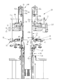
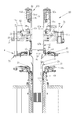
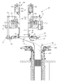
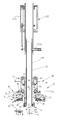
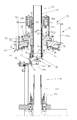
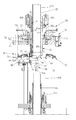
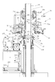
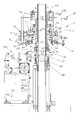
- FIG. 6 is a longitudinal sectional view showing a state in which the turning pipe holder and the lower knitted fabric presser are raised and the knitted fabric held by the fixed half dial is sandwiched between the half ring. It is a longitudinal cross-sectional view which shows the state which set the sewing machine unit to the 1st stitching position, and sewn the knitted fabric by linking using the transfer needle as a guide.
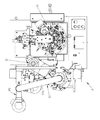
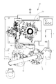
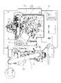
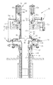
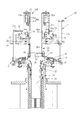
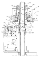
- the circular knitting machine system 10 of the present invention includes a circular knitting machine 11, a knitted fabric opening stitching device 12, and a knitted fabric transfer device 13.
- the circular knitting machine 11 includes a cross bar 14, a collar base 15, a latch ring 16, a yarn path device 17, a sinker bed 18, a knitting needle cylinder 19, a knitted fabric lowering pipe 20, and a yarn supply unit (not shown).
- a large number of knitting needles 21 are arranged at a constant pitch in the circumferential direction at the upper end of the knitting needle cylinder 19.
- a sinker 25 is provided in the gap between the knitting needles 21 so as to advance and retract in the radial direction of the knitting needle cylinder 19 by cam drive.
- loops are formed one after another by knitting yarn on the knitting needle 21, and as shown in FIG. 3, the sock as the knitted fabric 27 is formed with a mouth rubber part 27a and leg parts. 27b, the heel part 27c, the foot part 27d, and the toe part 27e are knitted into a cylindrical shape in this order.
- a knitted fabric opening stitching device 12 is attached to the side of the circular knitting machine 11.
- the knitted fabric opening stitching device 12 includes a sewing machine unit 100, a knitted fabric turnover unit 101, and a discharge unit 102. By interlocking these units 100 to 102, the opening edge of the knitted fabric 27 (see FIG. 3) can be sewn and discharged to a product receiving box (not shown).
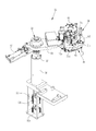
- the knitted fabric transfer apparatus 13 includes a knitted fabric transfer apparatus main body 30 and a moving mechanism 31 that moves the knitted fabric transfer apparatus main body 30.
- the moving mechanism 31 has a lifting / lowering rotating shaft 32 and a moving arm 33.
- the elevating rotary shaft 32 is supported by the guide tube portion 36 so as to be movable in the vertical direction and rotatable about the vertical axis.
- a moving arm 33 is fixed to the upper part of the lifting and lowering rotating shaft 32.
- a knitted fabric transfer device main body 30 is attached to the tip of the moving arm 33.
- a swinging air cylinder 37 is attached between the moving arm 33 and the guide cylinder portion 36.
- the oscillating air cylinder 37 rotates the moving arm 33 by 90 °, for example, in a horizontal plane around the up-and-down rotation shaft 32.
- the knitted fabric transfer device main body 30 is moved into an upper area (hereinafter referred to as a knitting stage) of the knitting needle cylinder 19 of the circular knitting machine 11 as shown in FIG. 17, and a knitted fabric opening as shown in FIG.
- the suturing device 12 is moved to an upper area of the turning pipe 110 (hereinafter referred to as a suturing stage).
- an arm up / down first air cylinder 32a, an arm up / down second air cylinder 32b, and an arm up / down third air cylinder 32c are connected in series from the bottom to the lower end of the up-and-down rotating shaft 32.
- the lifting rotary shaft 32 moves up and down in the vertical direction, and the moving arm 33 is set to a required height in a series of steps.
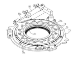
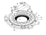
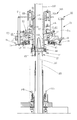
- the knitted fabric transfer apparatus main body 30 includes a transfer needle unit 40 and a transfer sinker unit 41.
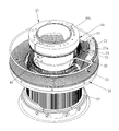
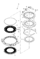
- the transfer needle unit 40 includes a fixed half dial 43 and a movable half dial 44 that hold the transfer needle 34, and a transfer needle holding cylinder 45 that holds these.
- the transfer needle unit 40 is moved up and down by the moving arm 33 (see FIG. 5) above the knitting needle cylinder 19, and the knitted fabric 27 held by the knitting needle 21 is transferred from the knitting needle 21 to the fixed half dial 43 and the movable half dial 44. Move to needle 34.
- the transfer needle holding cylinder 45 is rotatably attached to the transfer device base 51 via a bearing 50. As shown in FIG. 5, one end of the moving arm 33 is fixed to the transfer device base 51. As shown in FIG. 6, the transfer needle holding cylinder 45 is vertically divided into an upper holding cylinder part 45a and a lower holding cylinder part 45b, and the transfer needle rotating gear 52 is fixed therebetween. As shown in FIG. 7, the driving needle 53 b of the motor 53 is linked to the transfer needle rotation gear 52. The half dials 43 and 44 can be rotated via the transfer needle holding cylinder 45 by rotating the transfer needle rotating gear 52 by the rotation of the motor 53. The motor 53, the transfer needle rotation gear 52, the transfer needle holding cylinder 45, and the like constitute a rotation mechanism 106. As shown in FIG.
- the rotating mechanism 106 intermittently rotates the fixed half dial 43 in conjunction with the raising and lowering of the sewing needle 107 when the sewing unit 100 sews the inner loop 26a (see FIG. 24) of the knitted fabric 27. Then, the sewing needle 107 can be surely inserted into each inner loop 26a, and the sewing thread 108 can be passed through each inner loop 26a to be linked at a glance. 47 and 48, even when the knitted fabric 27 is moved and removed from the needle 34, the sewing needle 107 can be moved up and down while the knitted fabric 27 is held between the half ring 60 and the lower knitted fabric presser 115.
- the knitted fabric 27 can be sewn at a specified interval regardless of the loop interval.
- the illustration of the looper needle that cooperates with the sewing machine needle is omitted.
- the number of sewing threads is not limited to one, and two, three and a plurality of threads may be used.
- the fixed half dial 43 has a transfer needle holding groove 43b on the outer peripheral surface of the half dial main body 43a, and the transfer needle 34 is set in the transfer needle holding groove 43b. It is configured to hold down.
- the movable half dial 44 is configured similarly to the fixed half dial 43, and includes a half dial body 44a, a transfer needle holding groove 44b for holding the transfer needle 34, and a holder 44c. As a result, the first transfer needle group is attached to the fixed half dial 43 and the second transfer needle group is attached to the movable half dial 44.
- the fixed half dial 43 and the movable half dial 44 are attached by a hinge part 46 so that the movable half dial 44 can be rotated (reversed) by 180 ° with respect to the fixed half dial 43.
- the holder 43 c of the fixed half dial 43 is fixed to the transfer needle holding cylinder 45.
- the fixed half dial 43 and the movable half dial 44 are in an open state in which the transfer needle 34 is continuous in the circumferential direction.
- the knitted fabric 27 is transferred from the knitting needle 21 to the transfer needle 34.
- the movable half dial 44 is reversed and fitted to the fixed half dial 43, the half dials 43 and 44 are closed.
- this closed state as shown in FIG. 33, since the tips of the transfer needles 34 of the half dials 43 and 44 are in contact with each other, they are half of the knitted fabric opening held by the transfer needle 34 of the movable half dial 44.
- the inner loop 26a of the stationary half dial 43 is individually adjusted to the remaining half of the inner loop 26a held by the transfer needle 34 of the fixed half dial 43. As shown in FIG. 38, the knitted fabric 27 with the inner loop 26a thus fitted is transferred to the transfer needle 34 of the fixed half dial 43 (see FIG. 35), and then stitched by the sewing machine unit 100 as shown in FIG. Is called.
- the arrangement radius of the transfer needle 34 of the movable half dial 44 is slightly smaller than the arrangement radius of the transfer needle 34 of the fixed half dial 43. It is made smaller. For this reason, when the movable half dial 44 is closed as indicated by Z1 indicating an enlarged portion of FIG. 10, the moving needle 34 of the fixed half dial 43 is moved in the radial direction of the half dial 43 with respect to the moving needle 34 of the movable half dial 44. Will be offset. In this offset state, a tip storage groove 34 a is provided at the tip of the transfer needle 34 of the movable half dial 44 at a portion where the tip of the transfer needle 34 of the fixed half dial 43 is located.
- the tip of the transfer needle 34 of the fixed half dial 43 is placed in the tip storage groove 34a.
- the two transfer needles 34 can be connected as compared with the case where the tips of the transfer needles 34 are brought into contact with each other. It can be done reliably.
- the transfer needle holding cylinder 45 is formed with an insertion hole 45c in the vertical direction, and a lock shaft 56 is disposed in the insertion hole 45c so as to be movable up and down.
- the lower end portion of the lock shaft 56 enters the lock groove 44d of the movable half dial 44 and restricts the reversal of the movable half dial 44.
- a lock ring 57 is fixed to the upper end of the lock shaft 56.
- a lock cover 55 of the movable half dial 44 is attached to the transfer needle holding cylinder 45 so as to cover the transfer needle rotating gear 52.
- the lock cover 55 has a lock cylinder 55a and a stopper 55b.
- the lock ring 57 is moved up and down by the lock cylinder 55a. When the lock ring 57 is lowered, the lower end portion of the lock shaft 56 enters the lock groove 44d (see FIG. 8) to restrict the reversal of the movable half dial 44.
- a half ring lift cylinder 58 is attached to the upper part of the transfer needle holding cylinder 45 so as to be movable up and down.
- a half ring 60 is fixed to the half ring lifting cylinder 58 via a lifting shaft 59.
- the elevating shaft 59 is divided into upper and lower parts, and is attached to the transfer needle holding cylinder 45 so as to be movable up and down.
- the half-ring elevating cylinder 58 is composed of an inner cylinder 58a and an outer cylinder 58b, and these are configured to be rotatable around a cylinder center.
- a cylinder attachment plate 61 is attached to the lock cover 55 via a stay 61a above the outer cylinder 58b.
- a half-ring lowering first air cylinder 62a and a half-ring lowering second air cylinder 62b are attached between the cylinder mounting plate 61 and the outer cylinder 58b.
- the knitted fabric 27 is moved from the first position (see FIGS. 36 to 38) where the half ring 60 is retracted upward by selectively driving the first air cylinder 62a or the second air cylinder 62b. It moves down to the second position (see FIGS. 40, 47, and 48) removed from the transfer needle 34, or to the third position (see FIGS. 41 and 49) for cutting the sewing thread 108 after stitching. At the time of the lowering, the sewing thread 108 can be cut from the stitched knitted fabric 27.
- the loop is adjusted by the transfer needle rotating gear 52 and the motor 53, the half ring 60 that holds the knitted fabric opening at the time of sewing, the lifting mechanism 68 of the half ring 60, the reverse lock mechanism 69 of the movable half dial 44, and the like.
- the mechanism is configured. By interlocking each part of the loop matching mechanism, one half of the opening of the knitted fabric 27 is overlapped with the other half in the stitching stage of the knitted fabric opening stitching device 12, as will be described later. Sewing and cutting of the sewing thread 108 are performed.
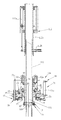
- the transfer sinker unit 41 includes a transfer sinker advance / retreat mechanism 70 and a transfer sinker elevating mechanism 71 for raising and lowering this in the vertical direction.
- the transfer sinker advance / retreat mechanism 70 includes a bed 72, a base 73, a transfer sinker 49, a sinker band 75, a cam holding ring 76, a cam 77, a cap 78, a rotating ring 79, and a set screw 74 in this order from the bottom.
- the moving sinker advance / retreat air cylinder 80 is provided.
- the bed 72 is attached to a ring-shaped base 73.
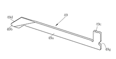
- the transfer sinker 49 has a belt-like transfer sinker main body 49a and a tip end portion 49b formed at the inner end of the transfer sinker main body 49a.
- the distal end portion 49b has an inclined portion 49d and is formed at an acute angle.
- the distal end portion 49b and the inclined portion 49d are formed thinner than the thickness of the transfer sinker main body 49a.
- the thickness of the transfer sinker body 49a is the same as the gap between the knitting needles 21.
- the thickness of the transfer sinker main body 49a is the same as the gap between the knitting needles 21 means that the sinker main body 49a enters the gap between the knitting needles 21 so that the sinker main body 49a can enter and move.
- the transfer sinker main body 49a is not the same in the strict sense that it cannot advance and retreat within the gap.
- a band groove 49 g is formed on the outer end surface of the transfer sinker 49. As shown in FIG. 11, a rubber or coil spring sinker band 75 is placed in the band groove 49g. The sinker band 75 biases the transfer sinker 49 inward.
- the cam 77 is composed of a cam main body 77a divided in the circumferential direction, and these cam main bodies 77a are connected in a ring shape by a set screw 74.
- the cam body 77 a is sandwiched by a cam holding ring 76 and a cap 78 so as to be movable in the radial direction of the cap 78.
- the cap 78 is provided with guide grooves 78a for guiding the cam body 77a in a substantially radial direction, twice as many as the number of cam bodies 77a.
- a cam groove 79a is formed in the rotating ring 79 in a direction intersecting with the radial direction.
- the set screw 74 passes through each cam groove 79a and the guide groove 78a and is screwed to the cam body 77a.
- the rotating ring 79 is rotatably held by the cap 78.
- the rotating ring 79 is formed with a protruding portion 79b protruding outward.
- a bracket portion 73 b for attaching the base end portion of the transfer sinker advance / retreat air cylinder 80 is extended to the base 73.
- a transfer sinker advance / retreat air cylinder 80 is attached to the projection 79b and the bracket portion 73b.
- the transfer sinker 49 Since the transfer sinker 49 is urged inward by the sinker band 75, the protrusion 49c of the transfer sinker 49 abuts on the outer peripheral surface of the cam 77. As the rod 80a of the transfer sinker advance / retreat air cylinder 80 moves in and out, the rotary ring 79 rotates by a predetermined angle.
- the transfer sinker 49 when the transfer sinker 49 is in the inserted state, the sinker 49 is inserted into the gap between the knitting needles 21 in the radial direction from the outer side to the inner side of the knitting needle cylinder 19.
- the upper end portion 49b is obliquely cut at the upper side portions of both side surfaces so that the tip portion 49b becomes gradually thinner toward the tip as compared with the transfer sinker main body 49a. Therefore, the tip portion 49b is reliably transferred to the gap between the knitting needles 21. Can be inserted. Further, after the insertion, since the transfer sinker main body 49a is positioned in the gap between the knitting needles 21, the knitting needle 21 can be guided in the circumferential direction.
- the tip 49b may be formed to have a constant thickness that is thinner than the transfer sinker main body 49a, in addition to being formed to be gradually thinner.
- the transfer sinker elevating mechanism 71 includes a transfer sinker elevating air cylinder 71a, a transfer sinker lowering first air cylinder 71b, a transfer sinker lowering second air cylinder 71c, a transfer sinker uplifting air cylinder 71d, and a cylinder mounting plate. 71e.
- the transfer sinker elevating air cylinder 71a is attached between the transfer device base 51 and the base 73 of the transfer sinker advance / retreat mechanism 70, and adjusts the distance between these bases.
- the operating points of the transfer sinker lowering first and second air cylinders 71b and 71c fixed to the transfer device base 51 and the transfer sinker uplifting air cylinder 71d are attached.
- the transfer sinker 49 can be raised and lowered within a predetermined range.
- the knitted fabric 27 of the knitting needle cylinder 19 can be moved to the moving needle 34 by linking the respective parts using the moving sinker advance / retreat mechanism 70 and the moving sinker elevating mechanism 71. Further, after the knitted fabric 27 is transferred to the transfer needle 34, the movable half dial 44 is reversed by the knitted fabric opening stitching device 12, and the inner loops 26a for the half circumference of the opening portion to be stitched are aligned with each other, The socks are completed by sewing with the sewing machine unit 100.
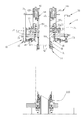
- the sewing machine unit 100 includes a sewing machine main body 103, a moving mechanism 104 for setting the sewing machine main body 103 in the toe opening, and a sewing machine advance / retreat positioning for selecting an approaching amount of the moving mechanism 104 to the toe opening.
- the knitted fabric turning unit 101 includes a turning pipe 110, a lower pipe lifting / lowering mechanism 111 that moves up and down with the lower end of the turning pipe 110 inserted, a turning pipe clamping mechanism 112, and a turning rod 113 (FIG. 42, 43) and a turning rod lifting mechanism (not shown).
- the circular knitting machine system 10 includes a transfer preparation step ST1, a knitted fabric transfer device moving step ST2, a knitted fabric loop aligning step ST3, a knitted fabric transferring step ST4, a knitted fabric moving step ST5, and a knitted fabric turning over step.
- Each process includes ST6, toe opening aligning step ST7, toe opening stitching step ST8, knitted fabric surface turning, discharging step ST9, and device returning step ST10, which are sequentially processed.
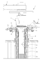
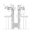
- FIG. 3 shows a longitudinal section at the knitting stage immediately after the completion of the circular knitting.
- the knitted fabric 27 immediately after knitting, in which the yarn is cut by the collar base 15, has final loops 26 hung on the respective knitting needles 21 (see FIG. 24) and is stored in the knitted fabric lowering pipe 20.
- the upper device including the gantry 15, the latch ring 16, and the yarn path device 17 is attached to the cross bar 14.
- the cross bar 14 swings in the vertical direction by an air cylinder (not shown).
- the knitted fabric lowering pipe 20 is connected to a suction blower via a valve (not shown), and the knitted fabric 27 is sucked downward in the knitted fabric lowering pipe 20.
- the knitted fabric lowering pipe 20 is configured to move up and down at a three-stage position of an upper stage, a middle stage, and a lower stage by a plurality of air cylinders.
- the cross bar 14 rotates upward, the gantry 15, the latch ring 16, and the yarn path device 17 move to the retracted position (see FIG. 16).
- the sinker cam 18 a and the rubber sinker cam (not shown) on the sinker bed 18 are activated, and the sinker 25 moves between the knitting needles 21 outward in the radial direction of the knitting needle cylinder 19.
- the 25 locking claws are separated from the knitting needle 21.
- the knitting needle 21 rises to the non-knitting level, and is in a state of projecting upward from the knitting needle cylinder 19 to the maximum.
- the knitted fabric lowering pipe 20 is raised and set in the upper stage.
- the final loop 26 of the knitted fabric 27 is positioned close to the latch (also referred to as a spatula) 21a of the knitting needle 21 (see FIG. 26).
- the knitting needle cylinder 19 is rotated to bring the knitting needle 21 and the transfer needle 34 into a corresponding positional relationship and then stopped, and locked by a lock device (not shown) so that the knitting needle cylinder 19 does not rotate carelessly.
- the transfer sinker lowering first and second cylinders 71b and 71c shown in FIG. 7 are in an extended state, and preparation of a stopper for lowering the transfer sinker 49 is performed.
- the knitted fabric transfer device moving step ST2 the following processing is performed. First, from the state shown in FIG. 15, when the moving arm 33 rotates by acting in the direction in which the rod of the oscillating air cylinder 37 is contracted, the knitted fabric transfer device main body 30 is attached to the knitting needle cylinder 19 as shown in FIGS. 17 and 18. It moves to the upper knitting stage, and it will be in the state of FIG.
- the following processing is performed.
- the arm upper and lower first air cylinders 32a and the arm upper and lower second air cylinders 32b shown in FIG. 5 are in a contracted state, and the transfer needle 34 is lowered from the position of FIG. 6, and as shown in FIG. Stop at the position. Further, the suction from the knitted fabric lowering pipe 20 is stopped.
- the transfer sinker raising / lowering air cylinder 71a (see FIG. 7) is in a non-operating state (free state), and as shown in FIG. 19, the transfer sinker lowering first air cylinder 71b is extended to the height of the extended state.
- the advance / retreat mechanism 70 is lowered by its own weight. Then, the transfer sinker advance / retreat mechanism 70 changes the transfer sinker 49 from the retracted state shown in FIG. 13A to the entering state shown in FIG. 13B.
- the knitted fabric lowering pipe 20 is lowered to the middle position. Further, the transfer sinker lowering first air cylinder 71b is contracted, the transfer sinker lowering second air cylinder 71c is moved to the height of the extended state, and the sinker advance / retreat mechanism 70 is lowered.
- the knitted fabric 27 is lowered by the transfer sinker 49 in the entering state, and the final loops are aligned so as to be at a fixed position (same horizontal level) in the vertical direction. Thereby, the transfer sinker 49 can always be brought into contact with the knitted fabric at a fixed position.
- the transfer sinker 49 is in the retracted position. Further, the transfer sinker lowering second air cylinder 71c (see FIG. 7) is contracted, and the transfer sinker 49 is moved down to a height at which the sinker advance / retreat mechanism 70 contacts the sinker cap 18b. Furthermore, the arm upper and lower third air cylinder 32c (see FIG. 5) is contracted. Thereby, as shown in FIG. 22, the tip of the transfer needle 34 contacts or approaches the back surface of the knitting needle 21.
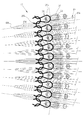
- FIG. 24 shows the knitted fabric 27 around the knitting needle 21 in a state where the final loop 26 is hung on the knitting needle 21.
- FIG. 25 shows the knitted fabric 27 around the knitting needle 21 in a state in which the sinker 49 is inserted in the gap between the knitting needles 21 from the outside toward the inside in the radial direction.
- FIG. 26 shows a side surface in a state where the transfer sinker 49 is inserted between the knitting needles 21. Since the transfer needle 34 is positioned above the inner loop 26 a in this state, the inner loop 26 a can be moved to the transfer needle 34 by lifting the knitted fabric 27 from below.
- the transfer needle 34 is moved to the inner back surface of the knitting needle 21 and the outer tip surface of the needle 34 is in contact with or in close proximity.
- the contact radius or the close proximity state is such that the arrangement radius of the transfer needle 34 of the movable half dial 44 is slightly smaller than the arrangement radius of the transfer needle 34 of the fixed half dial 43. It depends. For this reason, when both the half dials 43 and 44 are in the open state, when the knitting needle 21 approaches the transfer needle 34, the gap between the two is different, and the movement radius 34 of the movable half dial side is movable by the small arrangement radius.
- a gap is formed between the transfer needle 34 on the half dial side and the knitting needle 21.
- the gap is acceptable for the loop size. Accordingly, the knitting needle 21 and the transfer needle 34 are substantially integrated in the vertical direction, and the inner loop 26a of the knitted fabric 27 can be reliably transferred to the transfer needle 34.
- the transfer needle 34 that is separated from the knitting needle 21 by a certain distance faces the inner loop 26a. 34 can be inserted into the inner loop 26a of the same course.
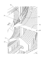
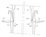
- the transfer needle 34 has a tip projection 34 e that is sharpened in a triangular pyramid shape, and the tip projection 34 e is offset inward and is slightly away from the knitting needle 21, so that the inside of the final loop 26 is inside. The needle 34 is securely inserted into the loop 26a.
- the transfer sinker is moved up and the air cylinder 71d is extended, and the knitted fabric 27 is moved up to the upper portion of the needle 34 by the transfer sinker 49.
- the transfer sinker 49 prevents the knitted fabric 27 from dropping from the transfer sinker 49, and the inner loop 26 a is attached to each transfer needle 34. Holds securely.
- the tip of the transfer needle 34 on the fixed half dial side is in contact with the back surface of the knitting needle 21, but the knitting needle 21 can be slightly swung inward, and the inner loop 26a is It is possible to smoothly move from the knitting needle 21 to the transfer needle 34 without being locked at these contact portions.
- the knitting needle 21 is swingably accommodated in the knitting needle holding groove of the knitting needle cylinder 19 in the radial direction of the knitting needle cylinder 19 although not shown. Further, since the tip protrusion 34e of the transfer needle 34 is offset and arranged inside, the transfer needle 34 is reliably inserted and guided to the inner loop 26a.
- the following processing is performed in the knitted fabric moving process ST5.
- the upper and lower arm first to third air cylinders 32a to 32c are extended, and the transfer device base 51 returns to the moving height (upper stage) as shown in FIG. Further, the knitted fabric lowering pipe 20 rises to the upper stage.
- the knitting needle cylinder 19 is rotated, and the knitting needle 21 is lowered until the knitting needle 21 reaches a float level that is hidden by the sinker 25. Thereby, even if the moving arm 33 is swung so that the knitted fabric 27 is pulled out from the knitted fabric lowering pipe 20 in the next step, the knitted fabric 27 does not come into contact with the knitting needle 21.
- the moving arm 33 starts to rotate toward the knitted fabric opening stitching device 12, as shown in FIG. And it moves to the position shown in FIG. Next, the knitted fabric lowering pipe 20 is in the lower position.
- the cross bar 14 swings from the retracted position to the knitting position, and in the knitting position, the cradle 15, the latch ring 16, and the yarn path device 17 are set, and the next knitting is performed. Be started.
- a suction switching valve (not shown) is opened and suction is performed from the turning pipe 110.
- the arm upper and lower first to third air cylinders 32a to 32c (see FIG. 5) are in a contracted state, and the knitted fabric transfer apparatus body 30 is in the lower position.
- a suction switching valve (not shown) is closed, and suction from the turning pipe 110 is stopped.
- the following processing is performed.
- the turning pipe 110 is raised by the raising of the turning pipe holder 109, and the turning pipe 110 is passed through the knitted fabric 27. Thereby, the knitted fabric is turned over.
- the clamping air cylinder 112b acts to hold the turning pipe 110.
- the transfer sinker 49 is in the retracted position, the transfer sinker elevating air cylinder 71a is contracted, and the transfer sinker 49 is retracted upward.
- the movable half dial reverse drive unit 85 moves from the retracted position to a position where it can act on the movable half dial 44. Further, the lock cylinder 55a of the lock cover 55 is extended, and the movable half dial 44 is unlocked.
- the half dial inversion driving unit 85 has an inversion pin receiving portion 85a into which an inversion pin 44e for inverting the movable half dial 44 is inserted, and inverts the movable half dial 44 by rotating 180 °.
- the transfer needle 34 of the movable half dial 44 is brought into contact with the transfer needle 34 of the fixed half dial 43 so as to be in a straight line (see FIG. 10).
- the reverse lock mechanism 69 is operated, and the state where the movable half dial 44 is closed is maintained. Thereafter, the movable half dial reverse drive unit 85 returns to the retracted position.
- the transfer sinker elevating air cylinder 71a acts in an extended state, and after the transfer sinker 49 is moved downward, the transfer sinker advance / retreat mechanism 70 is turned on. Enters the lower end of the inner loop 26 a hung on the transfer needle 34 of the movable half dial 44.
- the transfer sinker lift-up air cylinder 71d is in an extended state, the inner loop 26a of the transfer needle 34 on the movable half dial 44 side is lifted upward, and the transfer needle of the fixed half dial 43 is moved upward. 34.
- the transfer sinker lift air cylinder 71a is contracted, and the transfer sinker 49 retracts upward.
- the half dial reverse drive unit 85 is raised again, the reverse lock mechanism 69 is deactivated and the movable half dial 44 is unlocked in the reverse state.
- the lock cylinder 55a of the lock cover 55 is contracted, and the movable half dial 44 is opened away from the fixed half dial. It becomes locked again after becoming.
- the half dial inversion driving unit 85 is lowered and moved to the retracted position.
- the turning pipe holder 109 and the lower knitted fabric presser 115 are raised, and the knitted fabric 27 is sandwiched between the half ring 60 and the turning ring holder.
- the following processing is performed.
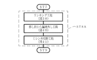
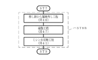
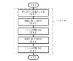
- this toe opening stitching step ST8 as shown in FIGS. 46A to 46D, four types of first toe opening stitching step ST8A to fourth toe opening stitching step ST8D can be selected.
- the first toe opening stitching step ST8A is a linking method, and includes a linking step, a knitted fabric removing step, and a sewing thread cutting step.
- the transfer needle rotating gear 52 is rotated by the motor 53 (see FIG. 7), and the stitching start portion is moved to the position of the sewing needle 107.
- the sewing machine advance / retreat positioning air cylinder 104b is extended, the sewing machine advance / retreat air cylinder 104a is extended to set the sewing machine main body 103 at the first stitching position.
- the sewing machine main body 103 is driven, and the motor 53 is driven in conjunction with the operation of the sewing needle 107, so that the inner loop 26a is sutured by the sewing needle 107 in a linking state one by one.
- the final loop 26 is wrapped by the linked sewing thread 108.
- the cross section of the needle needle guide groove having a V shape, a semicircular shape, or an arc shape, for example, along the axial direction of the transfer needle 34. 34b is formed.
- the lower end portion (tip portion) of the transfer needle 34 has an inclined surface 34 c inclined inward and a flat surface 34 d parallel to the axial direction of the transfer needle 34.
- a sewing needle guide groove 34b is opened in the inclined surface 34c. Accordingly, in sewing in the linking state, the sewing needle 107 enters the sewing needle guide groove 34b and descends, so that the tip of the sewing needle 107 is reliably guided into the inner loop 26a held by the transfer needle 34. Thereby, it can sew reliably for every inner loop 26a.
- the tip protrusion 34e of the transfer needle 34 is pointed in a triangular pyramid shape. As shown in FIG. 26, the tip protrusion 34e is formed on an extension line of the inner surface of the transfer needle 34. As a result, the tip protrusion 34e is offset inward. The tip protrusion 34e is offset inward to form an inclined surface 34f at the tip. The inclined surface 34f functions as a guide surface into which the tip protrusion 34e enters the inner loop 26a when the knitted fabric 27 is moved and moved upward by the rise of the sinker 49. Accordingly, the transfer needle 34 can surely enter the inner loop 26a, and the knitted fabric 27 can be transferred or closed based on the inner loop 26a.
- the second air cylinder 62b with the half ring lowered is in an extended state, and the position of the knitted fabric 27 sandwiched between the lower knitted fabric presser 115 and the half ring 60 is downward.
- the cutter advancing / retreating air cylinder 120 operates in the extending direction, and the cutter 121 is put in the upper part of the empty ring by the sewing thread 108.
- the cutter upper and lower air cylinders 122 are extended, and the cutter 121 is set to the cutting position of the empty ring.
- the cutter advance / retreat air cylinder 120 is in a contracted state, and the empty ring is cut by the retracting operation of the cutter 121.
- the cutter upper and lower air cylinders 122 are contracted to return the cutter 121 to the initial position.
- the above is the first toe opening stitching step ST8A.
- the second toe opening stitching step ST8B includes a knitted fabric removing step, a sewing step, and a sewing thread cutting step.
- the knitted fabric removing process and the sewing thread cutting process are the same processes as the first toe opening stitching process ST8A, and the description thereof is omitted.
- the knitted fabric removing step of the first toe opening stitching step ST8A about 10 stitches are made in the sewing machine body 103 at the end of the knitted fabric removing step because of the relationship performed after the linking step. Then, since there is no linking process, this is omitted.
- the needle rotation gear 52 is rotated by the motor 53 (see FIG. 7), and the sewing start portion is moved to the position of the sewing needle 107. Thereafter, in a state where the sewing machine advance / retreat positioning air cylinder 104b is extended, the sewing machine advance / retreat air cylinder 104a is extended to set the sewing machine main body 103 at the first stitching position.
- the sewing machine body 103 is driven, and the motor 53 is driven in conjunction with the operation of the sewing needle 107 to sew the knitted fabric with the sewing needle 107.
- the driving pitch of the motor 53 does not depend on the loop pitch, and can be arbitrarily set.
- the final loop 26 is wrapped by the sewing thread 108 that has been sewn. When the sewing of the knitted fabric is finished, about 10 stitches are formed on the sewing machine body 103 using the sewing thread 108, for example.
- the third toe opening stitching step ST8C has a second sewing step and a sewing thread cutting step following the knitted fabric removing step, the sewing step, and the sewing thread cutting step.
- the knitted fabric removal process, the first sewing process, and the sewing thread cutting process are the same as the second toe opening stitching process ST8B, and the description thereof is omitted.
- the second sewing step as shown in FIG. 48, the second ring air cylinder 62b is lowered again and the position of the knitted fabric 27 sandwiched between the lower knitted fabric presser 115 and the half ring 60 is set. Move upward. Next, the transfer needle rotating gear 52 is rotated by the motor 53 (see FIG.
- the sewing start portion is moved to the position of the sewing needle 107.
- the sewing machine advance / retreat positioning air cylinder 104b is contracted, the sewing machine advance / retreat air cylinder 104a further extends, and the sewing machine main body 103 is set at the second stitching position.
- the sewing machine body 103 is driven, and the motor 53 is driven in conjunction with the operation of the sewing needle 107, whereby the sewing needle 107 sews a position different from the initial stitching position of the knitted fabric.
- the driving pitch of the motor 53 does not depend on the loop pitch, and can be arbitrarily set.
- the final loop 26 and the first sewing thread 108 are wrapped by the main sewing thread 108. When the sewing of the knitted fabric is finished, about 10 stitches are formed on the sewing machine body 103 using the sewing thread 108, for example.
- the half-ring lowered second air cylinder 62b is in an extended state, and the position of the knitted fabric 27 sandwiched between the lower knitted fabric presser 115 and the half ring 60 is reached. Moves downward. Thereafter, the cutter advancing / retreating air cylinder 120 operates in the extending direction, and the cutter 121 is put in the upper part of the empty ring by the sewing thread 108. Next, the cutter upper and lower air cylinders 122 are extended, and the cutter 121 is set to the cutting position of the empty ring. Next, the cutter advance / retreat air cylinder 120 is in a contracted state, and the empty ring is cut by the retracting operation of the cutter 121. Thereafter, the cutter upper and lower air cylinders 122 are contracted to return the cutter 121 to the initial position. The above is the third toe opening stitching step ST8C.
- the fourth toe opening stitching step ST8D includes a second sewing step, a sewing thread cutting step, and a third toe opening stitching step ST8C after the first toe opening stitching step ST8A.
- a second sewing step a sewing thread cutting step
- a third toe opening stitching step ST8C after the first toe opening stitching step ST8A.
- Have Each step is the same as that in the first toe opening stitching step ST8A and the third toe opening stitching step ST8C, and a duplicate description is omitted.
- the final loop 26 in order to perform linking and sewing with respect to the inner loop 26a (see FIG. 25) rather than the final loop 26, the final loop 26 preferably uses FTY (Filament Twisted Yarn) yarn.
- FTY is generally used as a back thread for socks, and is composed of, for example, polyurethane and polyester having elasticity, and is thin and excellent in elasticity.
- the final loop 26 is easily adhered to the knitting needle 21 by using a flexible thread such as FTY.
- the distal end of the transfer needle 34 can be reliably inserted into the inner loop 26 a inside the final loop 26.
- the inner loop into which the transfer needle 34 is inserted is described as the loop 26a immediately before the final loop 26, but the transfer needle 34 is inserted into the previous two loops before or after that. May be. Further, the transfer needle 34 may be inserted in a state where the previous loop, the previous loop, etc. are mixed.
- the final loop 26 may be the same thread as the inner loop 26a.
- toe opening stitching steps ST8A to ST8D Since one of the four types of toe opening stitching steps ST8A to ST8D is selected and the toe opening is stitched, a stronger stitching can be performed in addition to stitching only by linking depending on the thickness and design of the knitted fabric. This can be realized by a single circular knitting machine system 10.
- the sewing machine advancing / retreating air cylinder 104a and the sewing machine advancing / retracting positioning air cylinder 104b are contracted to set the sewing machine main body 103 at the retracted position.
- the discharge port side suction switching valve (not shown) is opened, and suction is performed from the turning pipe 110 via the discharge unit 102.
- the lower knitted fabric retainer 115 descends to the retracted position, and the turning pipe holder 109 also moves once to the lowest level.
- the turning rod 113 rises together with the turning pipe holder 109, and the knitted fabric 27 is lifted in the turning pipe 110, whereby the knitted fabric 27 is inverted again so that the front side of the knitted fabric 27 comes out to the surface, as shown in FIG. It is discharged to a product receiving box (not shown) through the discharge tube 102a of the discharge unit 102.
- the discharge port side suction switching valve is closed, and the suction of the discharge tube 102a is released. Further, the first air cylinder 62a and the second air cylinder 62b are lowered, and the half ring 60 is retracted upward. Then, the turning pipe holder 109 is further raised to the upper position.
- the clamp air cylinder 112 b is contracted, and the holding of the turning pipe 110 is transferred from the clamping mechanism 112 to the turning pipe holder 109. Thereafter, the turning pipe holder 109 is lowered together with the turning rod 113 and the turning pipe 110 and set at the lower stage.
- the elevating air cylinder 112a of the clamp mechanism 112 shown in FIG. 43 is contracted, and the clamp pipe 112c is retracted upward. Further, the arm upper / lower second air cylinder 32b and the arm upper / lower third air cylinder 32c operate in the extending direction, and the moving arm 33 is set at the upper position. At this upper position, the moving arm 33 can move in the horizontal plane.
- the knitted fabric transfer device 13 sends the knitted fabric 27 to the knitted fabric opening stitching device 12, and the toe opening is closed. After that, it is discharged to the product receiving box via the discharge unit 102. Then, when the toe opening is closed by the knitted fabric opening stitching device 12, the next knitted fabric 27 is knitted by the circular knitting machine 11, and the knitted fabric 27 such as socks can be produced efficiently. .
- FIG. 45 summarizes the steps ST1 to ST10 in a flowchart.
- a knitted fabric stitching method for transferring the knitted fabric 27 from the knitting needle cylinder 19 of the circular knitting machine 11 to the knitted fabric transfer device 13 in order to close one end of the knitted fabric 27 knitted by the circular knitting machine 11, Transfer preparation step ST1, knitted fabric transfer device moving step ST2, knitted fabric loop aligning step ST3, knitted fabric transferring step ST4, knitted fabric moving step ST5, knitted fabric reversing step ST6, and toe opening adjusting step ST7 And a toe opening stitching step ST8, a knitted fabric surface turning and discharging step ST9, and a device return step ST10.
- the upper device of the circular knitting machine 11 is moved from the knitting position to the retracted position with respect to the knitted fabric 27 knitted by the circular knitting machine 11, and the circular knitting is performed.
- the final loop 26 (see FIG. 26) of the knitted fabric 27 held by the knitting needle 21 of the machine 11 is moved under the latch 21a of the knitting needle 21, and the knitting needle cylinder 19 of the circular knitting machine 11 is stopped at a fixed position.
- the knitted fabric transfer device moving step ST2 the knitted fabric transfer device 13 for transferring the inner loop 26a of the knitted fabric 27 is moved directly above the circular knitting machine 11, as shown in FIG.
- the transfer sinker 49 of the knitted fabric transfer device 13 is lowered in contact with the knitted fabric 27, and the height of the final loop 26 of the knitted fabric 27 is fixed in a vertical direction. Align.
- the transfer sinker 49 is moved to a height that exceeds the hook of the knitting needle 21, and the inner loop 26a of the knitted fabric 27 is transferred to the transfer needle 34.
- the knitted fabric moving step ST5 as shown in FIGS. 28 to 30, the knitted fabric 27 is moved from the knitting stage to the stitching stage by the knitted fabric transfer device 13.
- the turning pipe 110 is inserted into the knitted fabric 27, and the knitted fabric 27 is turned over.
- the first toe opening stitching step ST8A is a method by one linking. As shown in FIG. 38, the inner loops 26a overlapped with the transfer needle 34 of the fixed half dial 43 are connected to each loop (at a glance). Are sewn with a sewing thread 108.
- the inner loops 26a of the knitted fabric 27 are fed one at a time in conjunction with the raising and lowering of the sewing needle by the rotation mechanism 106 of the fixed half dial 43, and the inner loops 26a are securely stitched with the sewing thread 108 for each eye. Is done. Further, in the first toe opening stitching step ST8A, as shown in FIG. 39, the sewing needle is guided by the sewing needle guide groove 34b of the transfer needle 34 when the sewing needle is raised and lowered, so that each inner loop 38a is securely inserted. The sewing needle can be passed through.
- the second toe opening stitching step ST8B is a one-time sewing method. Before the sewing, as shown in FIG. 40, the heel knitted fabric 27 is sandwiched between the lower knitted fabric presser 115 and the half ring 60 inward. The loop 26a can be removed from the transfer needle 34, and can be sewn with a sewing machine without restriction on the loop pitch.
- the third toe opening stitching step ST8C is a method of further sewing after the second toe opening stitching step ST8B.
- the sewing unit 100 is moved again as shown in FIG. The strength can be increased.
- the fourth toe opening stitching step ST8D is a method of further sewing after the first toe opening stitching step ST8A.
- the sewing machine unit 100 is shown in FIG. As shown, it is possible to increase the strength of the stitched portion by sewing again after moving the heel.
- the turning rod 113 is inserted into the knitted fabric, whereby the knitted fabric 27 is returned to the front in the turning pipe 110. Thereafter, the knitted fabric 27 returned to the front in the turning pipe 110 is sucked, and is installed outside the circular knitting machine 11 via the discharge tube 102a of the discharge unit 102 as shown in FIG. Not discharged into the product receiving box.
- each operating unit is in an initial position state and waits for the next knitted fabric to be knitted.
- the transfer needle is inserted into the inner loop located inside the final loop, and the knitted fabric is transferred from the knitting needle to the transfer needle.
- the tip protrusion of the transfer needle is offset outward.
- the transfer needle can be inserted into the final loop and the knitted fabric can be transferred from the knitting needle to the transfer needle.
- the final loops can be linked instead of the inner loops.
- the knitted fabric when the knitted fabric is transferred from the knitting needle to the transfer needle, the loop inside the final loop is transferred to the transfer needle.
- the present invention is not limited to this, for example, when transferring from the knitting needle to the transfer needle.
- the knitted fabric is transferred to the final loop using the transfer needle whose tip protrusion is offset outward, and then transferred from the transfer needle to which the knitted fabric has been transferred in this final loop to the inner loop.
- the intermediate needle may be inserted into the inner loop, and the knitted fabric may be finally held by the inner loop.
- the inner loop is divided in half in the circumferential direction of the knitted fabric to form a first loop group and a second loop group.
- the intermediate needle may be a point needle that holds the knitted fabric for linking or a knitted fabric holding needle that holds the knitted fabric in a stage before being transferred to the point needle.
- the point needle of the sewing machine unit is inserted into the inner loop while the transfer needle holds the final loop, and the knitted fabric is moved to the point needle side.
- the linking portion can be made dense like the other loops, and the durability and the appearance quality can be improved.
- the point needle of the sewing machine unit is inserted into the inner loop while the transfer needle is held in the final loop, and the knitted fabric is moved to the point needle side.
- the final loop alignment step the half dials holding the point hands are aligned, and the opposing inner loop is moved to one half dial.
- the sewing thread is passed once per eye when linking the inner loop, but the number of times the sewing thread passes may be two or more. Further, by making the area through which the sewing thread passes through a plurality of times into several loops at the beginning of closing of the inner loop and several loops at the end of closing, the closed portion by linking can be reinforced. Further, the portion through which the sewing thread is passed a plurality of times is not limited to the beginning and end of closing, but may be an appropriate area. Further, the sewing thread that passes through the inner loop may be replaced, for example, for every plurality of pitches. For example, a loop for passing the sewing thread once and a loop for passing it twice may be alternated, and a loop that passes the sewing machine position a plurality of times every several pitches may be used.
Landscapes
- Engineering & Computer Science (AREA)
- Textile Engineering (AREA)
- Knitting Machines (AREA)
- Sewing Machines And Sewing (AREA)
Abstract
Description
1.編針が保持している最終ループを移し針(ステッチの取り除き手段)に移す第1編地移し工程、
2.移し針を保持しているハーフダイヤル(クラウン)を合わせ、対向する最終ループを一方のハーフダイヤルに移動させる最終ループ合わせ工程、
3.移し針が最終ループ保持した状態で、ミシンユニット(フックアップステーション)のポイント針(フックアップ刺状突起)を最終ループに挿入し、編地をポイント針側へ移す第2編地移し工程、
4.編地の最終ループをミシンユニットによりリンキング(フックアップ)するリンキング工程とを有する場合に、
第2編地移し工程にて、移し針が最終ループを保持した状態でミシンユニットのポイント針を内側ループに挿入し、編地をポイント針側へ移す。これにより、第1実施形態と同様にして、リンキング部分を他のループと同様に緻密にして、耐久性及び外観品質を向上することができる。
1.編針の保持している最終ループを移し針(ピックアップ部材)に移す第1編地移し工程、
2.移し針で最終ループ保持した状態でミシンユニット(ルーピングステーション)のポイント針(スパイク)を最終ループに挿入し、編地をポイント針側へ移す第2編地移し工程、
3.ポイント針を保持しているハーフダイヤル(半環状要素)を合わせ、対向する最終ループを一方のハーフダイヤルに移動させる最終ループ合わせ工程、
4.ミシンユニットで最終ループをリンキング(ルーピング)するリンキング工程を有する場合に、
第2編地移し工程にて、移し針が最終ループ保持した状態でミシンユニットのポイント針を内側ループに挿入し、編地をポイント針側へ移す。更に、最終ループ合わせ工程にて、ポイント針を保持しているハーフダイヤルを合わせ、対向する内側ループを一方のハーフダイヤルに移動させる。これにより、第1実施形態と同様にして、リンキング部分を他のループと同様に緻密にして、耐久性及び外観品質を向上することができる。
11 丸編機
12 編地開口部縫合装置
13 編地移し装置
19 編針シリンダ
21 編針
26 最終ループ
26a 内側ループ
27 編地
33 移動アーム
34 移し針
34b ミシン針ガイド溝
40 移し針ユニット
41 移しシンカユニット
43 固定ハーフダイヤル
44 可動ハーフダイヤル
45 移し針保持筒
46 ヒンジ部
49 移しシンカ
70 移しシンカ進退機構
71 移しシンカ昇降機構
85 可動ハーフダイヤル反転駆動部
100 ミシンユニット
101 編地裏返しユニット
102 排出ユニット
103 ミシン本体
106 回転機構
107 ミシン針
115 下編地押さえ
Claims (24)
- 丸編機で編まれた編地の一端を、前記丸編機の編針シリンダの編針から前記編針と同数の移し針に移した後に、前記一端をミシンユニットにより閉じる丸編機の編地縫合方法であって、
前記編針に掛けられていた前記編地の最終ループよりも内側に位置する内側ループを前記編地の円周方向に半分に分けて第1ループ群と第2ループ群とし、前記第1ループ群と前記第2ループ群を閉じる際に対向するループを合わせ、前記ミシンユニットのミシンにより縫合する丸編機の編地縫合方法。 - 編地を前記編針から移す際には前記移し針を用い、前記移し針と前記編針とを前記編針の軸方向に相対的に移動させ、前記編針の先端部内側面に前記移し針の先端部外側面を接近させて、
前記編針シリンダの各編針間の隙間に、前記編針シリンダの半径方向の外側から内側に、移し部材を入れ、前記移し部材の先端部により前記編針をガイドし、
前記移し部材を前記編針から前記移し針に前記編針の軸方向に移動させて、前記内側ループに、前記移し針の先端を挿入させ、前記編地を前記編針から前記移し針に移す請求項1記載の丸編機の編地縫合方法。 - 前記移し針は、先端突起が内側に寄せられている請求項1又は2記載の丸編機の編地縫合方法。
- 前記編針及び前記移し針は円周方向に等間隔で配置され、編針群及び移し針群を構成し、
前記移し針群は、180°間隔で第1移し針群及び第2移し針群に分けられ、前記第1ループ群が移される前記第1移し針群が固定ハーフダイヤルに、前記第2ループ群が移される前記第2移し針群が可動ハーフダイヤルに取り付けられ、
前記固定ハーフダイヤルに対して前記可動ハーフダイヤルはヒンジ部を介して、反転自在に取り付けられ、
前記固定ハーフダイヤル及び前記可動ハーフダイヤルが同一平面上に位置する開状態と、前記第1移し針群の先端に前記第2移し針群の先端が近接又は接触して両移し針が連続する閉状態とに、選択的にセットされる請求項1から3いずれか1項記載の丸編機の編地縫合方法。 - 前記閉状態で、前記第1移し針群と前記第2移し針群とは先端が前記各ハーフダイヤルの半径方向で位置をずらして配置され、前記第1移し針群と前記第2移し針群との一方の先端には、他方の先端を収納する収納溝が形成されており、前記閉状態で前記一方の先端が前記他方の収納溝に収納されて、前記第1移し針群と前記第2移し針群とが移し針軸方向に連続する請求項4記載の丸編機の編地縫合方法。
- 前記移し部材は、帯板状の移しシンカ本体と、傾斜部を有し鋭角に形成されている前記先端部とを有する移しシンカであり、
前記先端部は前記移しシンカ本体の厚みよりも薄く、前記移しシンカ本体の厚みは前記編針間の隙間と同一である請求項2から5いずれか1項記載の丸編機の編地縫合方法。 - 前記移しシンカは、シンカ進退機構により、前記編針シリンダの各編針間の隙間に前記編針シリンダの半径方向で外側から内側に挿入され、
前記移しシンカ及び前記移しシンカ進退機構は、シンカ昇降機構により、前記内側ループへ前記移し針の先端を挿入して、前記編地を前記編針から前記移し針に移す請求項6記載の丸編機の編地縫合方法。 - 前記内側ループを前記移し針に移す前に、前記編地の上方で、前記編針間の隙間に前記移し部材を挿入した後に下降させ、前記移し部材の先端部下面によって前記最終ループを押さえて、移し前の前記最終ループの高さを揃える請求項2から7いずれか1項記載の丸編機の編地縫合方法。
- 前記内側ループが前記移し針に移された後に、前記内側ループを縫合するために前記ミシンユニットに前記編地を移動し、前記ミシンユニットのミシン針の昇降に連動させて前記固定ハーフダイヤルを周方向に回転させる請求項4,5,4又は5を引用する請求項6から8いずれか1項記載の丸編機の編地縫合方法。
- 前記固定ハーフダイヤル側の前記移し針はミシン針ガイド溝を軸方向に有し、前記ミシン針の昇降の際に前記ミシン針ガイド溝により前記ミシン針を案内する請求項9記載の丸編機の編地縫合方法。
- 前記ミシンユニットは、前記ミシン針ガイド溝に前記ミシン針が入る第1縫合位置と、前記第1縫合位置よりも前記編地の内側に前記ミシン針が位置する第2縫合位置とに選択的にセットされ、前記第1縫合位置での前記ミシンユニットによるリンキング又は第1回目の縫製、前記第2縫合位置での第2回目の縫製が可能である請求項10記載の編地縫合方法。
- 前記固定ハーフダイヤルの内側に配されるハーフリングと、前記ハーフリングに対面して配される編地押さえとにより、前記編地を挟持した後に、前記内側ループを前記移し針から外して前記第1回目の縫製及び第2回目の縫製を行う請求項11記載の編地縫合方法。
- 丸編機で編まれた編地の一端を、前記丸編機の編針シリンダの編針から前記編針と同数の移し針に移した後に、前記一端をミシンユニットにより閉じる丸編機システムであって、
前記編針に掛けられている前記編地の最終ループよりも内側に位置する内側ループが挿入される移し針を保持し、前記編針シリンダの中心線方向に昇降して、前記編針から前記移し針が退避した退避状態と、前記編針に前記移し針が近接する近接状態となる移し針ユニットと、
前記移し針ユニットが前記近接状態のときに、前記編針から前記移し針へ前記編地を移す移し部材と、
前記内側ループを前記編地の円周方向に半分に分けて第1ループ群と第2ループ群とし、前記第1ループ群と前記第2ループ群を閉じる際に対向するループ同士を合わせるループ合わせ機構と、
前記ループ合わせ機構で合わされた前記ループ同士を縫合するミシンユニットと
を備える丸編機システム。 - 前記移し部材は、前記移し針ユニットが前記近接状態のときに前記編針シリンダの各編針間の隙間に、前記編針シリンダの半径方向で外側から内側に入れられ、先端部により前記編針をガイドする請求項13記載の丸編機システム。
- 前記移し針は、前記移し針ユニットに保持された状態で前記編針から離れる方向に寄せられている先端突起を有する請求項13又は14記載の丸編機システム。
- 前記編針及び前記移し針は円周方向に等間隔で配置され、編針群及び移し針群を構成し、
前記移し針ユニットは、前記第1ループ群が移される第1移し針群を保持する固定ハーフダイヤルと、前記第2ループ群が移される第2移し針群とを保持する可動ハーフダイヤルとを有し、
前記固定ハーフダイヤルに対して前記可動ハーフダイヤルはヒンジ部を介して、反転自在に取り付けられ、前記固定ハーフダイヤル及び前記可動ハーフダイヤルが同一平面上に位置する開状態と、前記第1移し針群の先端に前記第2移し針群の先端が近接又は接触して両移し針が連続する閉状態とに、選択的にセットされる請求項13から15いずれか1項記載の丸編機システム。 - 前記閉状態で、前記第1移し針群と前記第2移し針群とは先端が前記各ハーフダイヤルの半径方向で位置をずらして配置され、前記第1移し針群と前記第2移し針群との一方の先端には、他方の先端を収納する収納溝が形成されており、前記閉状態で前記一方の先端が前記他方の収納溝に収納されて、前記第1移し針群と前記第2移し針群とが移し針軸方向に連続する請求項16記載の丸編機システム。
- 前記移し部材は、帯板状の移しシンカ本体と、傾斜部を有し鋭角に形成されている先端部とを有する移しシンカであり、
前記先端部は前記移しシンカ本体の厚みよりも薄く、前記移しシンカ本体の厚みは前記編針間の隙間と同一である請求項17記載の丸編機システム。 - 前記移しシンカを、前記編針シリンダの各編針間の隙間に前記編針シリンダの半径方向で外側から内側に挿入する移しシンカ進退機構と、
前記移しシンカ及び前記移しシンカ進退機構を前記編針の軸方向に移動させて、前記内側ループへ前記移し針の先端を挿入させて、前記編地を前記編針から前記移し針に移す移しシンカ昇降機構と
を有する請求項18記載の丸編機システム。 - 前記内側ループを前記移し針に移す前に、前記編地の上方で、前記編針間の隙間に前記移しシンカを挿入した後に下降させ、前記移しシンカの先端部下面によって前記最終ループを押さえて、移し前の前記最終ループの高さを揃える請求項18又は19記載の丸編機システム。
- 前記内側ループが前記移し針に移された後に、前記内側ループを縫合するために前記ミシンユニットに前記編地を移す編地移し装置と、
前記ミシンユニットのミシン針の昇降に連動させて前記固定ハーフダイヤルを周方向に回転させる回転機構とを有する請求項16,17,16又は17を引用する請求項18から20いずれか1項記載の丸編機システム。 - 前記固定ハーフダイヤル側の前記移し針はミシン針ガイド溝を軸方向に有し、前記ミシン針の昇降の際に前記ミシン針ガイド溝により前記ミシン針を案内する請求項21記載の丸編機システム。
- 前記ミシンユニットは、前記ミシン針ガイド溝に前記ミシン針が入る第1縫合位置と、前記第1縫合位置よりも前記編地の内側に位置する第2縫合位置とに選択的にセットされ、前記第1縫合位置での前記ミシンユニットによるリンキング又は第1回目の縫製、前記第2縫合位置での第2回目の縫製が可能である請求項22記載の丸編機システム。
- 前記固定ハーフダイヤルの内側に配されるハーフリングと、前記ハーフリングに対面して配される編地押さえとにより、前記編地を挟持した後に、前記内側ループを前記移し針から外して第1回目の縫製及び第2回目の縫製を行う請求項23記載の丸編機システム。
Priority Applications (4)
| Application Number | Priority Date | Filing Date | Title |
|---|---|---|---|
| EP15836915.7A EP3187633B1 (en) | 2014-08-29 | 2015-03-24 | Circular knitting machine knitted fabric seaming method and circular knitting machine system |
| KR1020177006573A KR101783287B1 (ko) | 2014-08-29 | 2015-03-24 | 환편기의 편지 봉합방법 및 환편기 시스템 |
| JP2015533344A JP5854364B1 (ja) | 2014-08-29 | 2015-03-24 | 丸編機の編地縫合方法及び丸編機システム |
| CN201580045326.9A CN106795668B (zh) | 2014-08-29 | 2015-03-24 | 圆编机的针织物缝合方法以及圆编机系统 |
Applications Claiming Priority (2)
| Application Number | Priority Date | Filing Date | Title |
|---|---|---|---|
| JP2014-176630 | 2014-08-29 | ||
| JP2014176630 | 2014-08-29 |
Publications (1)
| Publication Number | Publication Date |
|---|---|
| WO2016031282A1 true WO2016031282A1 (ja) | 2016-03-03 |
Family
ID=55399188
Family Applications (1)
| Application Number | Title | Priority Date | Filing Date |
|---|---|---|---|
| PCT/JP2015/058877 Ceased WO2016031282A1 (ja) | 2014-08-29 | 2015-03-24 | 丸編機の編地縫合方法及び丸編機システム |
Country Status (7)
| Country | Link |
|---|---|
| EP (1) | EP3187633B1 (ja) |
| JP (1) | JP5854364B1 (ja) |
| KR (1) | KR101783287B1 (ja) |
| CN (1) | CN106795668B (ja) |
| TR (1) | TR201904912T4 (ja) |
| TW (1) | TWI537444B (ja) |
| WO (1) | WO2016031282A1 (ja) |
Cited By (1)
| Publication number | Priority date | Publication date | Assignee | Title |
|---|---|---|---|---|
| CN109576884A (zh) * | 2019-01-21 | 2019-04-05 | 杨志林 | 一种管状织物的缝合装置及方法 |
Families Citing this family (10)
| Publication number | Priority date | Publication date | Assignee | Title |
|---|---|---|---|---|
| TWI749282B (zh) * | 2018-01-18 | 2021-12-11 | 大康織機股份有限公司 | 縫合管狀針織物開口端之縫紉機及其編織方法 |
| CN109972281B (zh) * | 2019-04-19 | 2024-05-03 | 浙江嘉志利智能科技有限公司 | 一种带托物机构的管状织物成型装置及方法 |
| CN111850788B (zh) * | 2019-04-30 | 2025-05-13 | 诸暨艾尔马克智能科技有限公司 | 一种编织机沉降片装置 |
| IT201900017141A1 (it) * | 2019-09-24 | 2021-03-24 | Da Kong Entpr Co Ltd | Dispositivo di cucitura o di rimagliatura per la chiusura di un manufatto tubolare a maglia |
| IT201900023433A1 (it) * | 2019-12-10 | 2021-06-10 | Lonati Spa | Dispositivo prelevatore per operare il prelievo di un manufatto tubolare a maglia da una macchina circolare per maglieria, calzetteria o simile |
| CN113493955B (zh) * | 2020-03-19 | 2022-10-28 | 典洋针织机械股份有限公司 | 高密度织物的移圈装置及其方法 |
| CN113737383B (zh) * | 2021-08-16 | 2023-05-23 | 浙江罗速设备制造有限公司 | 一种袜子的拾取转移缝合装置及方法 |
| CN113818146B (zh) * | 2021-10-24 | 2022-11-29 | 浙江罗速设备制造有限公司 | 一种减少干涉的对目式袜子缝制装置以及方法 |
| CN116988220A (zh) * | 2023-08-18 | 2023-11-03 | 陈仲纪 | 一种具有推出拾取压紧功能的袜子转移装置 |
| CN118932595B (zh) * | 2024-10-15 | 2024-12-27 | 浙江伟焕机械制造股份有限公司 | 一种缝袜机 |
Citations (3)
| Publication number | Priority date | Publication date | Assignee | Title |
|---|---|---|---|---|
| US2047888A (en) * | 1934-07-28 | 1936-07-14 | Scott & Williams Inc | Weight device |
| JP2004143614A (ja) * | 2002-10-23 | 2004-05-20 | Nagata Seiki Co Ltd | 靴下移し装置 |
| JP2006503991A (ja) * | 2002-10-21 | 2006-02-02 | ファブリテックス エスアールエル | 管状ニット製品の縁を接合するための方法及び装置 |
Family Cites Families (9)
| Publication number | Priority date | Publication date | Assignee | Title |
|---|---|---|---|---|
| JPS5116557B2 (ja) | 1972-12-12 | 1976-05-25 | ||
| JP2002266208A (ja) | 2001-03-14 | 2002-09-18 | Nagata Seiki Co Ltd | 靴下を機外に搬出する搬出方法および搬出装置 |
| IT1358379B1 (it) * | 2004-12-28 | 2009-04-01 | Franco Sciacca | Metodo e apparecchiatura per produrre articoli di calzetteria e maglieria tubolare e tessuti a maglia con macchine mono fornitura |
| ITMI20080397A1 (it) * | 2008-03-10 | 2009-09-11 | Lonati Spa | Procedimento ed apparecchiatura per eseguire la chiusura di un manufatto tubolare a maglia in corrispondenza di una sua estremita' assiale, al termine del suo ciclo di produzione su una macchina circolare per maglieria, calzetteria o simile. |
| IT1392646B1 (it) * | 2009-01-30 | 2012-03-16 | N T A S R L | Dispositivo di prelievo di una calza da un macchinario cilindrico per la produzione di manufatti tubolari con estremita cucita |
| TWI448595B (zh) * | 2010-04-06 | 2014-08-11 | Da Kong Entpr Co Ltd | Sock body delivery device and method thereof |
| ITMI20130050A1 (it) * | 2013-01-16 | 2014-07-17 | Lonati Spa | Procedimento per attuare la chiusura automatizzata di un'estremita' assiale di un manufatto tubolare e il suo scarico in assetto a rovescio ed apparecchiatura per la sua esecuzione. |
| ITFI20130081A1 (it) * | 2013-04-12 | 2014-10-13 | Gianni Conti | "metodo e macchina per la tessitura di manufatti tubolari a maglia" |
| TWI539050B (zh) * | 2013-11-15 | 2016-06-21 | Da Kong Entpr Co Ltd | Sewing sock machine needle plate |
-
2015
- 2015-03-24 JP JP2015533344A patent/JP5854364B1/ja active Active
- 2015-03-24 CN CN201580045326.9A patent/CN106795668B/zh active Active
- 2015-03-24 WO PCT/JP2015/058877 patent/WO2016031282A1/ja not_active Ceased
- 2015-03-24 EP EP15836915.7A patent/EP3187633B1/en active Active
- 2015-03-24 TR TR2019/04912T patent/TR201904912T4/tr unknown
- 2015-03-24 KR KR1020177006573A patent/KR101783287B1/ko active Active
- 2015-08-12 TW TW104126177A patent/TWI537444B/zh active
Patent Citations (3)
| Publication number | Priority date | Publication date | Assignee | Title |
|---|---|---|---|---|
| US2047888A (en) * | 1934-07-28 | 1936-07-14 | Scott & Williams Inc | Weight device |
| JP2006503991A (ja) * | 2002-10-21 | 2006-02-02 | ファブリテックス エスアールエル | 管状ニット製品の縁を接合するための方法及び装置 |
| JP2004143614A (ja) * | 2002-10-23 | 2004-05-20 | Nagata Seiki Co Ltd | 靴下移し装置 |
Cited By (1)
| Publication number | Priority date | Publication date | Assignee | Title |
|---|---|---|---|---|
| CN109576884A (zh) * | 2019-01-21 | 2019-04-05 | 杨志林 | 一种管状织物的缝合装置及方法 |
Also Published As
| Publication number | Publication date |
|---|---|
| EP3187633A4 (en) | 2017-09-06 |
| TWI537444B (zh) | 2016-06-11 |
| TW201610255A (zh) | 2016-03-16 |
| TR201904912T4 (tr) | 2019-05-21 |
| KR101783287B1 (ko) | 2017-10-23 |
| KR20170033447A (ko) | 2017-03-24 |
| CN106795668B (zh) | 2018-04-17 |
| JP5854364B1 (ja) | 2016-02-09 |
| EP3187633B1 (en) | 2019-03-06 |
| JPWO2016031282A1 (ja) | 2017-04-27 |
| EP3187633A1 (en) | 2017-07-05 |
| CN106795668A (zh) | 2017-05-31 |
Similar Documents
| Publication | Publication Date | Title |
|---|---|---|
| JP5854364B1 (ja) | 丸編機の編地縫合方法及び丸編機システム | |
| JP5813192B1 (ja) | 丸編機の編地移し方法及び装置 | |
| RU2085637C1 (ru) | Способ соединения краев вязаного трубчатого изделия и устройство для его осуществления | |
| US6164091A (en) | Method and apparatus for seaming edges of knitted articles | |
| RU2114226C1 (ru) | Способ соединения двух кромок вязаного на кругловязальной машине трубчатого изделия, в частности стачивания мыска носка, и устройство для его осуществления | |
| CZ20011295A3 (cs) | Způsob a zařízení pro ąití ąpičky ponoľky | |
| US5551260A (en) | Method for joining two edges of a knitted tubular article upon completion thereof | |
| KR20150143410A (ko) | 관형상 편성 물품을 편성하기 위한 방법 및 기계 | |
| US20190226131A1 (en) | Sewing machine and the method for closing open end of tubular knitted article | |
| EP2024544B1 (en) | Method and integrated system for knitting a stocking on a circular knitting machine and for closing the toe of the stocking | |
| JP2791938B2 (ja) | ニットした管状物品の完成後、該物品の二端を結合する方法 | |
| WO2025021428A1 (en) | Method and apparatus for closing a tubular knitted article at one of its axial ends, at the end of its production cycle on a circular knitting machine for hosiery or the like | |
| US6170299B1 (en) | Method and apparatus for transferring a loop from a selected needle to an adjacent needle for creating a decorative open-work pattern | |
| TWI865503B (zh) | 用於在一圓形針織機上製造管狀針織物件之方法、用於自一圓形針織機拾取管狀針織物件之拾取裝置,以及用於製造管狀針織物件之系統 | |
| HK40058356A (en) | Method and apparatus for producing tubular knitted articles with a closed toe | |
| HK40058356B (en) | Method and apparatus for producing tubular knitted articles with a closed toe | |
| CZ20023028A3 (en) | Device for closing toes in knitting machine |
Legal Events
| Date | Code | Title | Description |
|---|---|---|---|
| ENP | Entry into the national phase |
Ref document number: 2015533344 Country of ref document: JP Kind code of ref document: A |
|
| 121 | Ep: the epo has been informed by wipo that ep was designated in this application |
Ref document number: 15836915 Country of ref document: EP Kind code of ref document: A1 |
|
| NENP | Non-entry into the national phase |
Ref country code: DE |
|
| ENP | Entry into the national phase |
Ref document number: 20177006573 Country of ref document: KR Kind code of ref document: A |
|
| REEP | Request for entry into the european phase |
Ref document number: 2015836915 Country of ref document: EP |
|
| WWE | Wipo information: entry into national phase |
Ref document number: 2015836915 Country of ref document: EP |