WO2016031738A1 - チューブ - Google Patents
チューブ Download PDFInfo
- Publication number
- WO2016031738A1 WO2016031738A1 PCT/JP2015/073633 JP2015073633W WO2016031738A1 WO 2016031738 A1 WO2016031738 A1 WO 2016031738A1 JP 2015073633 W JP2015073633 W JP 2015073633W WO 2016031738 A1 WO2016031738 A1 WO 2016031738A1
- Authority
- WO
- WIPO (PCT)
- Prior art keywords
- tube
- ink
- ultraviolet
- light transmittance
- organic pigment
- Prior art date
- Legal status (The legal status is an assumption and is not a legal conclusion. Google has not performed a legal analysis and makes no representation as to the accuracy of the status listed.)
- Ceased
Links
Images

Classifications
-
- B—PERFORMING OPERATIONS; TRANSPORTING
- B41—PRINTING; LINING MACHINES; TYPEWRITERS; STAMPS
- B41J—TYPEWRITERS; SELECTIVE PRINTING MECHANISMS, i.e. MECHANISMS PRINTING OTHERWISE THAN FROM A FORME; CORRECTION OF TYPOGRAPHICAL ERRORS
- B41J2/00—Typewriters or selective printing mechanisms characterised by the printing or marking process for which they are designed
- B41J2/005—Typewriters or selective printing mechanisms characterised by the printing or marking process for which they are designed characterised by bringing liquid or particles selectively into contact with a printing material
- B41J2/01—Ink jet
- B41J2/17—Ink jet characterised by ink handling
- B41J2/175—Ink supply systems ; Circuit parts therefor
-
- C—CHEMISTRY; METALLURGY
- C08—ORGANIC MACROMOLECULAR COMPOUNDS; THEIR PREPARATION OR CHEMICAL WORKING-UP; COMPOSITIONS BASED THEREON
- C08J—WORKING-UP; GENERAL PROCESSES OF COMPOUNDING; AFTER-TREATMENT NOT COVERED BY SUBCLASSES C08B, C08C, C08F, C08G or C08H
- C08J3/00—Processes of treating or compounding macromolecular substances
- C08J3/20—Compounding polymers with additives, e.g. colouring
- C08J3/22—Compounding polymers with additives, e.g. colouring using masterbatch techniques
-
- C—CHEMISTRY; METALLURGY
- C08—ORGANIC MACROMOLECULAR COMPOUNDS; THEIR PREPARATION OR CHEMICAL WORKING-UP; COMPOSITIONS BASED THEREON
- C08K—Use of inorganic or non-macromolecular organic substances as compounding ingredients
- C08K3/00—Use of inorganic substances as compounding ingredients
- C08K3/01—Use of inorganic substances as compounding ingredients characterized by their specific function
- C08K3/014—Stabilisers against oxidation, heat, light or ozone
-
- C—CHEMISTRY; METALLURGY
- C08—ORGANIC MACROMOLECULAR COMPOUNDS; THEIR PREPARATION OR CHEMICAL WORKING-UP; COMPOSITIONS BASED THEREON
- C08K—Use of inorganic or non-macromolecular organic substances as compounding ingredients
- C08K3/00—Use of inorganic substances as compounding ingredients
- C08K3/18—Oxygen-containing compounds, e.g. metal carbonyls
- C08K3/20—Oxides; Hydroxides
- C08K3/22—Oxides; Hydroxides of metals
-
- C—CHEMISTRY; METALLURGY
- C08—ORGANIC MACROMOLECULAR COMPOUNDS; THEIR PREPARATION OR CHEMICAL WORKING-UP; COMPOSITIONS BASED THEREON
- C08K—Use of inorganic or non-macromolecular organic substances as compounding ingredients
- C08K5/00—Use of organic ingredients
- C08K5/0008—Organic ingredients according to more than one of the "one dot" groups of C08K5/01 - C08K5/59
- C08K5/0041—Optical brightening agents, organic pigments
-
- F—MECHANICAL ENGINEERING; LIGHTING; HEATING; WEAPONS; BLASTING
- F16—ENGINEERING ELEMENTS AND UNITS; GENERAL MEASURES FOR PRODUCING AND MAINTAINING EFFECTIVE FUNCTIONING OF MACHINES OR INSTALLATIONS; THERMAL INSULATION IN GENERAL
- F16L—PIPES; JOINTS OR FITTINGS FOR PIPES; SUPPORTS FOR PIPES, CABLES OR PROTECTIVE TUBING; MEANS FOR THERMAL INSULATION IN GENERAL
- F16L11/00—Hoses, i.e. flexible pipes
- F16L11/04—Hoses, i.e. flexible pipes made of rubber or flexible plastics
- F16L11/12—Hoses, i.e. flexible pipes made of rubber or flexible plastics with arrangements for particular purposes, e.g. specially profiled, with protecting layer, heated, electrically conducting
-
- C—CHEMISTRY; METALLURGY
- C08—ORGANIC MACROMOLECULAR COMPOUNDS; THEIR PREPARATION OR CHEMICAL WORKING-UP; COMPOSITIONS BASED THEREON
- C08J—WORKING-UP; GENERAL PROCESSES OF COMPOUNDING; AFTER-TREATMENT NOT COVERED BY SUBCLASSES C08B, C08C, C08F, C08G or C08H
- C08J2323/00—Characterised by the use of homopolymers or copolymers of unsaturated aliphatic hydrocarbons having only one carbon-to-carbon double bond; Derivatives of such polymers
- C08J2323/02—Characterised by the use of homopolymers or copolymers of unsaturated aliphatic hydrocarbons having only one carbon-to-carbon double bond; Derivatives of such polymers not modified by chemical after treatment
- C08J2323/04—Homopolymers or copolymers of ethene
- C08J2323/06—Polyethene
-
- C—CHEMISTRY; METALLURGY
- C08—ORGANIC MACROMOLECULAR COMPOUNDS; THEIR PREPARATION OR CHEMICAL WORKING-UP; COMPOSITIONS BASED THEREON
- C08K—Use of inorganic or non-macromolecular organic substances as compounding ingredients
- C08K3/00—Use of inorganic substances as compounding ingredients
- C08K3/18—Oxygen-containing compounds, e.g. metal carbonyls
- C08K3/20—Oxides; Hydroxides
- C08K3/22—Oxides; Hydroxides of metals
- C08K2003/2237—Oxides; Hydroxides of metals of titanium
- C08K2003/2241—Titanium dioxide
-
- C—CHEMISTRY; METALLURGY
- C08—ORGANIC MACROMOLECULAR COMPOUNDS; THEIR PREPARATION OR CHEMICAL WORKING-UP; COMPOSITIONS BASED THEREON
- C08K—Use of inorganic or non-macromolecular organic substances as compounding ingredients
- C08K3/00—Use of inorganic substances as compounding ingredients
- C08K3/18—Oxygen-containing compounds, e.g. metal carbonyls
- C08K3/20—Oxides; Hydroxides
- C08K3/22—Oxides; Hydroxides of metals
- C08K2003/2296—Oxides; Hydroxides of metals of zinc
Definitions
- the present invention relates to a tube for supplying a fluid such as ink.
- ink of each color such as cyan, magenta, yellow, and black is supplied from an ink tank in a printer body to a print head side through a tube.
- some relatively large inkjet printers use UV (ultraviolet) curable ink by taking advantage of the fact that they can be cured instantaneously by irradiating ultraviolet rays immediately after printing.
- UV curable ink to reduce the amount of UV light radiated from the UV irradiation section to cure the UV curable ink, as in the conventional example, to reach the vicinity of the ink flow path, or to shield the ink flowing in the tube from the UV light Ink tubes using black resin to which carbon black or the like is added are used.
- an inkjet printer using UV curable ink is provided with a mechanism for reducing the illuminance of ultraviolet rays with respect to the ink supply path including the ink tube, but it is difficult to completely prevent ink curing in the ink tube.
- inside the printer housing it is protected from the ultraviolet rays contained in sunlight, fluorescent lights, etc. around the printer, but the printer body cover may be opened during printer maintenance work, etc.
- the inside of the housing is exposed to ultraviolet rays.
- the curing of the UV curable ink as described above is prevented by using a black resin in which carbon black or the like having ultraviolet shielding properties is added to the material of the ink tube.
- an ink tube using a black resin to which carbon black or the like is added as in the above conventional example cannot sufficiently shield the ultraviolet rays, and it is difficult to completely eliminate problems such as clogging due to ink curing. there were.
- black resin because black resin is used, the ink tube becomes black and opaque, and it is difficult to check the flow of ink in the tube from the outside, so check the inside of the tube from the outside of the ink tube when a defect occurs There was an inconvenience that could not be done.
- the ink hardens in the tube and adheres to the inner wall of the tube, it may be necessary to wash away with chemicals or replace it with a new tube. This increases the running cost of the printer.
- the present invention has been made in view of the above problems, and an object of the present invention is to provide a tube that can effectively protect the fluid in the tube from the influence of ultraviolet rays and is visible from the outside.
- an ultraviolet absorber comprising a yellow organic pigment and an inorganic compound
- the tube of the present invention is a tube having an ultraviolet shielding layer made of a resin composition in which a yellow organic pigment and an ultraviolet absorber made of an inorganic compound are dispersed.
- the light transmittance at a wavelength of 350 nm is 4% to 14% and the light transmittance at a wavelength of 400 nm is 5% to 19%.
- the tube of the present invention is a tube having an ultraviolet shielding layer made of a resin composition in which a yellow organic pigment and an ultraviolet absorbent made of an inorganic compound are dispersed.
- the yellow organic pigment is an organic pigment having a yellow hue of 10R to 5GY in the Munsell hue ring (20 hues).
- the yellow organic pigment mainly absorbs ultraviolet light having a wavelength of about 350 nm or less and visible light having a short wavelength and has a characteristic of allowing visible light having a relatively long wavelength to pass through.
- the ultraviolet absorber which consists of an inorganic type compound as a ultraviolet-ray shielding layer
- zinc oxide has the property to absorb the ultraviolet rays below about 380 nm.
- a high ultraviolet shielding rate can be obtained and visible light can be transmitted, so that both the ultraviolet shielding rate and visibility can be achieved.
- conventionally known light stabilizers, antioxidants and the like can be used in combination, and deterioration of the tube can be suppressed by dispersing at least one of these together with the yellow organic pigment and the inorganic compound.
- a master batch is used in which the pigment is treated to improve dispersibility and kneaded into the resin at a high concentration to form pellets.
- a blend of the master batch and resin is put into a single screw extruder and formed, but that alone does not sufficiently disperse the pigment and the UV absorber, and the effect of the present invention Cannot be obtained.
- the tube of the present invention uses a master batch, and further kneads the blended resin with a twin screw extruder into pellets, and improves the dispersion by using an extruder using a dalmage screw.
- the tube of the present invention has a light transmittance in terms of thickness when the tube is diluted 10 times by volume, and the light transmittance at a wavelength of 350 nm is 4% to 14% and the light transmittance at a wavelength of 400 nm.
- the rate is 5% or more and 19% or less.
- the definition of “when the tube is diluted 10 times by volume” is because the difference in the effect becomes clear by diluting 10 times, and the UV absorber and the pigment are measured by measuring the transmittance.
- the ink curability of the resin composition containing can be determined.
- the resin for diluting the tube the resin used as the base of the tube to be diluted is used.
- the tube is a single-layer tube
- the tube is cut out, the volume is measured, and the mixture with the base resin of 9 times the volume is the same as the wall thickness of the tube Form into a thick film.
- the light transmittance in the thickness direction is measured using the molded film, and the measured value is set as the light transmittance in terms of thickness.
- the tube is a multi-layer tube
- the volume is measured, mixed with the resin used as the base of the ultraviolet shielding layer, diluted 10 times in volume ratio, and then formed into a film having the same thickness as the thickness of the ultraviolet shielding layer.
- the light transmittance in the thickness direction is measured, and the measured value is taken as the light transmittance in terms of thickness.
- a 10-fold diluted resin is formed into a 0.25 mm thick film, and the molded film is used. And measure the light transmittance in the thickness direction.
- the measured value of the light transmittance of a film having a thickness of 0.25 mm can be converted into the light transmittance of the tube thickness or the thickness of the ultraviolet shielding layer by applying the Lambert-Beer law.
- the light transmittance converted to the thickness of the tube or the thickness of the ultraviolet shielding layer is defined as the light transmittance converted to the thickness.
- the reason why the light transmittance at a wavelength of 350 nm is 4% or more and 14% or less is that when the transmittance is higher than 14%, the substantial concentration of the ultraviolet absorber is mainly too low to transmit and transmit ultraviolet rays.
- the ink is cured by absorbing ultraviolet energy. Also, if it is lower than 4%, the substantial concentration of the UV absorber is mainly too high, which impairs the visibility of the tube contents. With this configuration, ink curing can be prevented without impairing visibility.
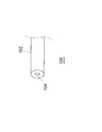
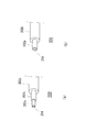
- FIG. 1 It is a perspective view which shows the tube of the 1st Embodiment of this invention. It is a figure for demonstrating the method of the ink hardening test done about the film of the resin composition used for the ultraviolet-ray shielding layer of the tube of the 1st Embodiment of this invention. It is a perspective view which shows the tube of the 2nd Embodiment of this invention, (a) shows the tube of the 3 layer structure, (b) shows the tube of the 2 layer structure.
- FIG. 1 is a perspective view showing a tube according to a first embodiment of the present invention.
- the tube of this embodiment is used as a tube for supplying ink of each color such as cyan, magenta, yellow, and black from an ink tank in a printer body in an ink jet printer to the print head.
- the tube layer structure is mainly shown, and the entire length direction of the tube and the configuration on the ink jet printer side which is irrelevant to the essence of the present invention, that is, the ink tank side on which the tube is mounted, The configuration on the print head side is omitted.
- the tube 100 of the present embodiment is a single-layered tube composed of a tube layer 102 made of an ultraviolet (UV) shielding flexible resin.
- Reference numeral 104 denotes a tube lumen.
- the tube layer 102 uses a resin composition in which a yellow organic pigment and an ultraviolet absorber made of an inorganic compound are dispersed as an ultraviolet shielding layer, and the ultraviolet shielding layer absorbs the organic pigment and the ultraviolet absorption in the resin composition.
- It is a light transmittance in terms of thickness when the standard deviation ⁇ of the concentration of the agent is dispersed so that ⁇ 0.02% or less and the tube is diluted 10 times by volume, and light having a wavelength of 350 nm
- the transmittance is 4% to 14%, and the light transmittance at a wavelength of 400 nm is 5% to 19%.
- Table 1 shows a comparison of Examples 1 to 11 in which the values of the respective constituent requirements were changed with respect to the film of the resin composition used for the ultraviolet shielding layer of the tube of the present invention described above and the configuration of the present invention not having Examples 1 to 8 show the results of film light transmittance, ink curing test, and visibility test.
- Example 1 to 11 and Comparative Examples 1 to 6 the resin blended in a container was melt-kneaded at 150 ° C. using a twin-screw extruder (Technobel, 20 mm diameter) and pelletized.
- Comparative Examples 7 and 8 what was blended in a container was used for molding as it was.
- C Tube forming
- the tube molded in the above (C) was cut out, measured and pulverized, mixed with a base resin having a volume 9 times that of the tube, and kneader (A sample was obtained by kneading at 140 ° C. for 15 minutes using a Toyo Seiki Co., Ltd. laboratory lab plast mill). The obtained sample was melted by a 160 ° C. heat press and formed into a 0.25 mm film having the same thickness as the tube thickness.
- the light transmittance was measured using a UV-visible spectrophotometer UV-1200 manufactured by Shimadzu Corporation for the light transmittance of a 10-fold diluted film by volume.
- UV curable ink (cyan) was placed in a stainless steel pot shown in FIG. 2 and covered with a sample film (0.25 mm). Then, it was left for a day and night outdoors on a sunny day. After this test, the degree of cure of the UV curable ink was evaluated as ⁇ : no change, ⁇ : gelation, x: cure.
- D is an opening
- 120 is a pot body
- 122 is a UV curable ink
- 124 is a UV shielding flexible resin film.
- Visibility test A sample film (0.25 mm) is placed on white paper printed with cyan, magenta, and yellow lines (thickness 0.7 mm), and the lines are separated by 300 mm in a bright room. Evaluated whether it can be recognized. The evaluation criteria were classified into the following three. ⁇ : All color lines could be recognized. ⁇ : A yellow line could not be recognized. ⁇ : All color lines could not be recognized. *
- the concentration of an ultraviolet absorber made of an inorganic compound was measured as a marker for measuring the dispersion state, and the standard deviation was calculated.
- the sample tube was pulverized, a sheet having a thickness of 2 mm was prepared by a heat press method (160 ° C.), and the element concentration was analyzed by an X-ray analysis microscope XGT5000WR manufactured by Horiba.
- XGT5000WR X-ray analysis microscope
- the beam diameter was 1.2 mm
- the measurement time was 100 sec
- 10 measurements were made in a range of about 40 mm ⁇ 40 mm
- the standard deviation was calculated.
- examples 7 and 8, and Comparative Example 4 titanium oxide was used as a measurement marker.
- Comparative Examples 1, 2, 5, and 6 the substantial concentration of the yellow organic pigment was insufficient, and ink curing occurred.
- Comparative Example 3 the substantial concentration of the yellow organic pigment and the ultraviolet absorber (zinc oxide) was excessive, and the ink could be prevented from curing, but the visibility was not obtained.
- Comparative Example 4 the substantial concentration of the yellow organic pigment and the ultraviolet absorber (titanium oxide) was excessive, and the ink could be prevented from curing, but the visibility was not obtained.
- Comparative Example 7 corresponds to a conventional black resin tube, the ink was cured and the visibility was not obtained.
- Comparative Example 8 had the same blending ratio as Example 3, but was molded by a conventional method.
- the dispersion was insufficient and the ultraviolet ray shielding effect of the ink was not fully exhibited, and the ink was cured. That is, in order to obtain a sufficient ultraviolet shielding effect that does not affect the ink inside the tube even when exposed to strong ultraviolet rays such as sunlight, and visibility to confirm the fluid inside the tube, a pigment and an ultraviolet absorber It is important to disperse uniformly and highly.
- FIGS. 3A and 3B are perspective views showing a tube according to the second embodiment of the present invention, in which FIG. 3A shows the tube with the three-layer structure, and FIG. 3B shows the tube with the two-layer structure.
- the tube 200 in FIG. 3A is configured as a three-layer tube having an inner layer 202a, an adhesive layer 202b, and an outer layer 202c.
- the inner layer 202a uses a fluororesin
- the outer layer 202c uses the same resin composition as in the first embodiment.
- 204 indicates the tube lumen.
- a tube 300 having a two-layer structure having an inner layer 302a and an outer layer 302b may be used.
- 304 shows the tube lumen.
- the multi-layer tube of the second embodiment was also subjected to an ink curing test and a visibility test using a UV lamp and sunlight.
- the test results are shown in Table 2.
- Ink Curing Test In an ink curing test using a UV lamp, a 100 mm multilayer tube was filled with UV curable ink (cyan), and both ends were sealed. In order to evaluate the ultraviolet shielding property, an aswan handy UV lamp LUV-16 (wavelength 365 nm) was irradiated at a distance of 100 mm. After 2 hours, 24 hours, and 840 hours, the ink in the tube was lightly washed, then the tube was cut, and the degree of curing of the ink was evaluated according to the following criteria.
- LUV-16 wavelength 365 nm
- UV curing is performed in the same manner as the ink curing test in the first embodiment.
- the functional ink cyan
- Transparent water and air were alternately flowed into the visibility test tube, and whether or not the boundary between water and air was visible was evaluated according to the following criteria. ⁇ : The boundary of the air was visible. X: The boundary of air was not visually recognized.
- the fluororesin of the inner layer has an ink barrier property, and the ink transmittance of the entire tube at 60 ° C. is 1% or less. It can also be.
- an ink permeation test of a multilayer tube was also conducted. That is, the ink was filled in the multilayer tube, both ends were sealed, and the change in the weight of the ink after a predetermined time was measured.
- Example 13 in Table 2 and newly as Comparative Example 10 a tube 500 mm of ⁇ 3 ⁇ ⁇ 3.8 was filled with UV curable ink, sealed at both ends, and placed at 60 ° C.
- Example 10 For 1 week, The weight change of the ink was measured.
- the comparative example 10 was comprised by the multilayer tube which changed the inner layer of the tube of Example 13 to adhesive ETFE and the outer layer to the thermoplastic urethane, respectively. After one week, the ink weight decreased by 0.16% in Example 13 and 1.79% in Comparative Example 10.
- Example 13 since the ink barrier fluororesin was used for the inner layer, the change in the weight of the ink was less than that in Comparative Example 10, and the ink transmittance could be suppressed.
- the ink transmittance of the whole tube per week at 60 ° C. is 1% or less per 500 mm of the tube length. Can be suppressed as much as possible, and ink loss can be prevented. That is, while obtaining the above-described visibility, the ink transmittance can be reduced to prevent ink loss.
- the UV shielding property and visibility of the tube have been examined with respect to the UV curable ink used in the ink jet printer or the like, but the tube of the present invention is not limited to these applications. is there.
- a tube through which a fluid that may be deteriorated by ultraviolet rays flows may be used.
- the present invention can be applied to the case where a powder that may be deteriorated due to ultraviolet rays flows inside the tube.
- the concept of the present invention can be extended to pipe bodies other than tubes, film packaging materials, and the like.
- the present invention can be widely applied to any tube having the structure of the claims regardless of its size, material, and use.
Landscapes
- Chemical & Material Sciences (AREA)
- Medicinal Chemistry (AREA)
- Health & Medical Sciences (AREA)
- Chemical Kinetics & Catalysis (AREA)
- Polymers & Plastics (AREA)
- Organic Chemistry (AREA)
- General Engineering & Computer Science (AREA)
- Engineering & Computer Science (AREA)
- Mechanical Engineering (AREA)
- Ink Jet (AREA)
- Rigid Pipes And Flexible Pipes (AREA)
- Laminated Bodies (AREA)
- Compositions Of Macromolecular Compounds (AREA)
Abstract
Description

実施例1~11と比較例1~8の各試料の作成方法としては、φ3×φ3.5の単層チューブ(図1を参照)を成形した。
各試料の作成方法の詳細は、以下のとおりである。
(A) 使用原料
(1)実施例1~6、比較例1~3、比較例8については、低密度ポリエチレン(LDPE)として三菱化学製変性LDPE モディックL502、 黄色顔料(色相H:5Y)マスターバッチ、 酸化亜鉛マスターバッチ(平均粒径0.2μm)
(2)実施例7、8比較例4については、低密度ポリエチレン(LDPE)として三菱化学製変性LDPE モディックL502、黄色顔料(色相H:5Y)マスターバッチ、酸化チタン(平均粒径0.2μm)
(3)実施例9、10、比較例5については、低密度ポリエチレン(LDPE)として三菱化学製変性LDPE モディックL502、黄色顔料(色相H:5YR)マスターバッチ、酸化亜鉛マスターバッチ(平均粒径0.2μm)
(4)実施例11、比較例6については、低密度ポリエチレン(LDPE)として三菱化学製変性LDPE モディックL502、黄色顔料(色相H:10Y)マスターバッチ、酸化亜鉛マスターバッチ(平均粒径0.2μm)
(5)比較例7については、低密度ポリエチレン(LDPE)として三菱化学製変性LDPE モディックL502、黒色顔料マスターバッチ
(B)チューブ成形材料の製造
(A) に記載した各原料を容器に入れて混合して使用した。
(1)実施例1~11、比較例1~6は、容器でブレンドした樹脂を二軸押出機( テクノベル社製 口径20mm)を使用して、150℃で溶融混練し、ペレット化した。
(2)比較例7、8は、容器でブレンドしたものをそのまま成形に用いた。
(C)チューブ成形
(1)実施例1~11、比較例1~6は、単軸押出機(口径 30mm、L/D=28 )にて、単層チューブを成形した。スクリューは、顔料及び 紫外線吸収剤の分散を高めるために、ダルメージスクリューを使用した。
(2)比較例7、8は、単軸押出機(口径 30mm、L/D=28 )にて、単層チューブを成形した。スクリューは、一般的な成形に使用されるフルフライトスクリューを使用した。
(D)試料のフィルムの作成
(C)で成形したチューブを粉砕し、160℃のヒートプレスで溶融させて、厚さ0.25mmのフィルムに成形した。
本実施例、比較例では、分散状態を測定するマーカーとして無機系化合物からなる紫外線吸収剤の濃度を測定し、その標準偏差を算出した。
試料のチューブを粉砕し、ヒートプレス法(160℃)により厚さ2mmのシートを作成し、堀場製作所製 X線分析顕微鏡 XGT5000WR により、元素濃度を分析した。尚、このX線分析顕微鏡は、ビーム径1.2mm、測定時間は100secとし、約40mm×40mmの範囲で10箇所測定を行い、その標準偏差を計算した。実施例1~6、9~11および比較例1~3、5、6、8は酸化亜鉛を、実施例7、8、比較例4は酸化チタンを測定のマーカーとした。
実施例1~6、9~11では、黄色顔料と紫外線吸収剤(酸化亜鉛)の実質的濃度が適正であり、インクの硬化は起こらなかった。また、十分な視認性が得られた。黄色の有機顔料の色相が異なるとUV遮蔽効果と視認性を両立できる濃度範囲は異なるが、ほぼ同様の効果を示した。
実施例7、8では、無機系化合物からなる紫外線吸収剤として酸化亜鉛の代わりに酸化チタンを使用した。酸化亜鉛同様、インクの硬化を防ぐことができ、視認性も得られた。尚、酸化チタンを黄色の有機顔料と分散させた実施例7及び8では、特に400nmの波長のUV遮蔽に効果があり、視認性も得られた。
比較例1、2、5及び6では、主に黄色の有機顔料の実質的濃度が不十分であり、インクの硬化が起きた。
比較例3では、黄色の有機顔料と紫外線吸収剤(酸化亜鉛)の実質的濃度が過剰であり、インクの硬化を防ぐことはできたが、視認性が得られなかった。
比較例4では、黄色の有機顔料と紫外線吸収剤(酸化チタン)の実質的濃度が過剰であり、インクの硬化を防ぐことはできたが、視認性が得られなかった。
比較例7は、従来の黒色樹脂チューブに相当するものなので、インクの硬化がおきてしまい、視認性も得られなかった。
比較例8は、実施例3と同じ配合比だが、従来の方法で成形されたものであり、分散が不十分でインクの紫外線遮蔽効果が十分に発揮されず、インクの硬化が起きた。即ち、太陽光のような強い紫外線に暴露してもチューブ内部のインクに影響を与えない十分な紫外線遮蔽効果と、チューブ内部の流体を確認できる視認性を得るためには、顔料と紫外線吸収剤を均一に、高度に分散させることが重要である。
図3は、本発明の第2の実施形態のチューブを示す斜視図であり、(a)は、その3層構造のチューブ、(b)は、その2層構造のチューブを示す。
図3(a)のチューブ200は、内層202a、接着層202b及び外層202cを有する3層構造のチューブとして構成されている。内層202aは、フッ素樹脂、外層202cは、上記の第1の実施形態と同様の樹脂組成物を使用している。204は、チューブ内腔を示す。尚、図3(b)に示すように、第2の実施形態の変形例として、内層302a、外層302bを有する2層構造のチューブ300に構成しても良い。304は、チューブ内腔を示す。

チューブ内に透明な水と空気を交互に流し、水と空気の境界が視認できるかどうかを以下の基準で評価した。
○:空気の境界を視認できた。
×:空気の境界を視認できなかった。
本実施形態の効果を確認するため、多層チューブのインク透過試験も行った。即ち、多層チューブにインクを充填し、両端を封止した上で、一定時間経過後のインクの重量変化を測定した。
具体的には、表2の実施例13と、新たに比較例10として、φ3×φ3.8のチューブ500mmにUV硬化性インクを充填し、両端を封止し、60℃で1週間置き、インクの重量変化を測定した。
尚、比較例10は、実施例13のチューブの内層を接着性ETFE、外層を熱可塑性ウレタンにそれぞれ変更した多層チューブにより構成した。
1週間後、インクの重量は、実施例13は、0.16%、比較例10は、1.79%減少した。
実施例13では、内層にインクバリア性フッ素樹脂を用いているので、比較例10に比べてインクの重量変化が少なく、インク透過率を抑えることができた。
尚、本発明の第3の実施形態のように、更に、60℃における1週間あたりのチューブ全体のインク透過率が、チューブ長さ500mmあたり1%以下であるものとすることで、インク透過率を極力抑えて、インクの目減りを防止することができる。即ち、上述した視認性を得ながらも、インク透過率は小さくして、インクの目減りを防止することができる。
102 チューブ層、
104、204、304 チューブ内腔、
202a、302a 内層、202b 接着層、202c、302b 外層
Claims (1)
- 黄色の有機顔料と無機系化合物からなる紫外線吸収剤とが分散する樹脂組成物を紫外線遮蔽層としたチューブであって、
前記樹脂組成物における前記有機顔料と前記紫外線吸収剤の濃度の標準偏差σがσ=0.02%以下になるように分散させ、
前記チューブを体積比で10倍に希釈したときの肉厚換算した光透過率であって、
波長350nmの光透過率が4%以上14%以下、
波長400nmの光透過率が5%以上19%以下であることを特徴とするチューブ。
Priority Applications (4)
| Application Number | Priority Date | Filing Date | Title |
|---|---|---|---|
| KR1020177005484A KR20170049508A (ko) | 2014-08-29 | 2015-08-21 | 튜브 |
| EP15835652.7A EP3187762A4 (en) | 2014-08-29 | 2015-08-21 | Tube |
| CN201580046295.9A CN106605093A (zh) | 2014-08-29 | 2015-08-21 | 管 |
| IL250815A IL250815B (en) | 2014-08-29 | 2017-02-27 | Pipe |
Applications Claiming Priority (2)
| Application Number | Priority Date | Filing Date | Title |
|---|---|---|---|
| JP2014176521A JP6499840B2 (ja) | 2014-08-29 | 2014-08-29 | チューブ |
| JP2014-176521 | 2014-08-29 |
Publications (1)
| Publication Number | Publication Date |
|---|---|
| WO2016031738A1 true WO2016031738A1 (ja) | 2016-03-03 |
Family
ID=55399630
Family Applications (1)
| Application Number | Title | Priority Date | Filing Date |
|---|---|---|---|
| PCT/JP2015/073633 Ceased WO2016031738A1 (ja) | 2014-08-29 | 2015-08-21 | チューブ |
Country Status (7)
| Country | Link |
|---|---|
| EP (1) | EP3187762A4 (ja) |
| JP (1) | JP6499840B2 (ja) |
| KR (1) | KR20170049508A (ja) |
| CN (1) | CN106605093A (ja) |
| IL (1) | IL250815B (ja) |
| TW (1) | TW201613768A (ja) |
| WO (1) | WO2016031738A1 (ja) |
Cited By (1)
| Publication number | Priority date | Publication date | Assignee | Title |
|---|---|---|---|---|
| US12129938B2 (en) | 2021-08-31 | 2024-10-29 | Saint-Gobain Performance Plastics Corporation | Tube and method for making same |
Families Citing this family (2)
| Publication number | Priority date | Publication date | Assignee | Title |
|---|---|---|---|---|
| JP2018174647A (ja) * | 2017-03-31 | 2018-11-08 | スリーエム イノベイティブ プロパティズ カンパニー | 識別構造及び識別部材 |
| JP7481120B2 (ja) * | 2020-01-31 | 2024-05-10 | 東拓工業株式会社 | 多層樹脂製ホース |
Citations (4)
| Publication number | Priority date | Publication date | Assignee | Title |
|---|---|---|---|---|
| JPS5577705A (en) * | 1978-12-07 | 1980-06-11 | Toyobo Co Ltd | Production of laminated polarizing plate |
| JP2004167968A (ja) * | 2002-11-22 | 2004-06-17 | Konica Minolta Holdings Inc | インクジェットプリンタ |
| JP2006130829A (ja) * | 2004-11-08 | 2006-05-25 | Konica Minolta Medical & Graphic Inc | インクジェットプリンタ |
| JP2006168350A (ja) * | 2004-11-18 | 2006-06-29 | Konica Minolta Medical & Graphic Inc | インクジェットプリンタ |
Family Cites Families (5)
| Publication number | Priority date | Publication date | Assignee | Title |
|---|---|---|---|---|
| JP3613990B2 (ja) * | 1998-08-20 | 2005-01-26 | 凸版印刷株式会社 | 熱可塑性樹脂組成物および成形体 |
| JP2004181829A (ja) * | 2002-12-04 | 2004-07-02 | Toshiba Tec Corp | 積層チューブおよびこれを備えるインクジェット記録装置 |
| JP2006077075A (ja) * | 2004-09-08 | 2006-03-23 | Sumitomo Metal Mining Co Ltd | 樹脂組成物と紫外線遮蔽用透明樹脂成形体および紫外線遮蔽用透明樹脂積層体 |
| CN103665506B (zh) * | 2012-08-29 | 2016-03-30 | 中国石油化工股份有限公司 | 一种色母粒及其制备方法和应用 |
| JP5786016B2 (ja) * | 2012-12-27 | 2015-09-30 | 富士フイルム株式会社 | 偏光板保護フィルム、偏光板、並びに液晶表示装置 |
-
2014
- 2014-08-29 JP JP2014176521A patent/JP6499840B2/ja active Active
-
2015
- 2015-08-21 CN CN201580046295.9A patent/CN106605093A/zh active Pending
- 2015-08-21 WO PCT/JP2015/073633 patent/WO2016031738A1/ja not_active Ceased
- 2015-08-21 EP EP15835652.7A patent/EP3187762A4/en not_active Withdrawn
- 2015-08-21 KR KR1020177005484A patent/KR20170049508A/ko not_active Ceased
- 2015-08-25 TW TW104127745A patent/TW201613768A/zh unknown
-
2017
- 2017-02-27 IL IL250815A patent/IL250815B/en active IP Right Grant
Patent Citations (4)
| Publication number | Priority date | Publication date | Assignee | Title |
|---|---|---|---|---|
| JPS5577705A (en) * | 1978-12-07 | 1980-06-11 | Toyobo Co Ltd | Production of laminated polarizing plate |
| JP2004167968A (ja) * | 2002-11-22 | 2004-06-17 | Konica Minolta Holdings Inc | インクジェットプリンタ |
| JP2006130829A (ja) * | 2004-11-08 | 2006-05-25 | Konica Minolta Medical & Graphic Inc | インクジェットプリンタ |
| JP2006168350A (ja) * | 2004-11-18 | 2006-06-29 | Konica Minolta Medical & Graphic Inc | インクジェットプリンタ |
Non-Patent Citations (1)
| Title |
|---|
| See also references of EP3187762A4 * |
Cited By (1)
| Publication number | Priority date | Publication date | Assignee | Title |
|---|---|---|---|---|
| US12129938B2 (en) | 2021-08-31 | 2024-10-29 | Saint-Gobain Performance Plastics Corporation | Tube and method for making same |
Also Published As
| Publication number | Publication date |
|---|---|
| JP2016049714A (ja) | 2016-04-11 |
| EP3187762A1 (en) | 2017-07-05 |
| TW201613768A (en) | 2016-04-16 |
| IL250815A0 (en) | 2017-04-30 |
| EP3187762A4 (en) | 2018-04-18 |
| KR20170049508A (ko) | 2017-05-10 |
| IL250815B (en) | 2020-10-29 |
| JP6499840B2 (ja) | 2019-04-10 |
| CN106605093A (zh) | 2017-04-26 |
Similar Documents
| Publication | Publication Date | Title |
|---|---|---|
| JP6499840B2 (ja) | チューブ | |
| EP1657072B1 (en) | Laser-imaging method | |
| JP6633611B2 (ja) | 良好分散高負荷量カラーマスターバッチのための方法および組成物 | |
| Khajavi et al. | Strategies for controlling release of plastic compounds into foodstuffs based on application of nanoparticles and its potential health issues | |
| EP3214148B1 (en) | Heat-ray-shielding particles | |
| TWI811435B (zh) | 層合玻璃用中間膜、層合玻璃、及玻璃構成體 | |
| CN103974828B (zh) | 多层可热恢复物品 | |
| DE60120887T2 (de) | Polyester Schutzfilm mit verbesserten UV - Stabilisierungseigenschaften | |
| JP2009023100A (ja) | 紫外線を吸収し可視光線を透過する積層材料と該積層材料を用いた包装体およびプレススルーパッケージ並びにシュリンクラベル | |
| WO2013125515A1 (ja) | 遮光容器 | |
| JP7075713B2 (ja) | 分散体、着色層、着色膜、着色基材、着色合わせ基材、およびインク | |
| CN106117759A (zh) | 一种双滴头式内镶贴片滴灌带及其制备方法 | |
| JP2006224317A (ja) | 遮光性積層フィルムおよびそのフィルムを用いた遮光性包装体 | |
| CN104448526B (zh) | 一种型材保护膜用着色母料及其制备方法 | |
| EP3938442A1 (de) | Hochvoltkomponenten | |
| WO2016060092A1 (ja) | インクジェットプリンタuvインク供給用チューブ | |
| CN209989305U (zh) | 一种防紫外的覆膜 | |
| CN107160801A (zh) | 一种原色膜 | |
| JP3885140B2 (ja) | 印刷インキ組成物及び包装体 | |
| JP6625273B2 (ja) | レーザーマーキング発色性のカード用樹脂組成物、及びそのカード | |
| TWI916462B (zh) | 密封薄膜 | |
| Tury et al. | Enhancement of fluorescent stability of 2, 5-bis-2-(5-tert-butyl)-benzoxazolyl-thiophene (BBOT) containing LDPE films | |
| JP4483242B2 (ja) | 包装構造体及び包装構造体の再生処理方法 | |
| AU2024339582A1 (en) | Master batch, composition, near-infrared shielding transparent resin molded body, and near-infrared shielding transparent multilayer body | |
| CN103287013A (zh) | 一种高隔热防紫外线的太阳膜 |
Legal Events
| Date | Code | Title | Description |
|---|---|---|---|
| 121 | Ep: the epo has been informed by wipo that ep was designated in this application |
Ref document number: 15835652 Country of ref document: EP Kind code of ref document: A1 |
|
| ENP | Entry into the national phase |
Ref document number: 20177005484 Country of ref document: KR Kind code of ref document: A |
|
| REEP | Request for entry into the european phase |
Ref document number: 2015835652 Country of ref document: EP |
|
| WWE | Wipo information: entry into national phase |
Ref document number: 250815 Country of ref document: IL Ref document number: 2015835652 Country of ref document: EP |
|
| NENP | Non-entry into the national phase |
Ref country code: DE |