WO2016035575A1 - 電動モータ試験システム - Google Patents
電動モータ試験システム Download PDFInfo
- Publication number
- WO2016035575A1 WO2016035575A1 PCT/JP2015/073517 JP2015073517W WO2016035575A1 WO 2016035575 A1 WO2016035575 A1 WO 2016035575A1 JP 2015073517 W JP2015073517 W JP 2015073517W WO 2016035575 A1 WO2016035575 A1 WO 2016035575A1
- Authority
- WO
- WIPO (PCT)
- Prior art keywords
- electric motor
- cogging torque
- dynamometer
- motor
- measuring
- Prior art date
- Legal status (The legal status is an assumption and is not a legal conclusion. Google has not performed a legal analysis and makes no representation as to the accuracy of the status listed.)
- Ceased
Links
Images


Classifications
-
- G—PHYSICS
- G01—MEASURING; TESTING
- G01M—TESTING STATIC OR DYNAMIC BALANCE OF MACHINES OR STRUCTURES; TESTING OF STRUCTURES OR APPARATUS, NOT OTHERWISE PROVIDED FOR
- G01M17/00—Testing of vehicles
- G01M17/007—Wheeled or endless-tracked vehicles
- G01M17/0072—Wheeled or endless-tracked vehicles the wheels of the vehicle co-operating with rotatable rolls
-
- G—PHYSICS
- G01—MEASURING; TESTING
- G01L—MEASURING FORCE, STRESS, TORQUE, WORK, MECHANICAL POWER, MECHANICAL EFFICIENCY, OR FLUID PRESSURE
- G01L3/00—Measuring torque, work, mechanical power, or mechanical efficiency, in general
- G01L3/24—Devices for determining the value of power, e.g. by measuring and simultaneously multiplying the values of torque and revolutions per unit of time, by multiplying the values of tractive or propulsive force and velocity
-
- G—PHYSICS
- G01—MEASURING; TESTING
- G01L—MEASURING FORCE, STRESS, TORQUE, WORK, MECHANICAL POWER, MECHANICAL EFFICIENCY, OR FLUID PRESSURE
- G01L5/00—Apparatus for, or methods of, measuring force, work, mechanical power, or torque, specially adapted for specific purposes
- G01L5/13—Apparatus for, or methods of, measuring force, work, mechanical power, or torque, specially adapted for specific purposes for measuring the tractive or propulsive power of vehicles
-
- G—PHYSICS
- G01—MEASURING; TESTING
- G01M—TESTING STATIC OR DYNAMIC BALANCE OF MACHINES OR STRUCTURES; TESTING OF STRUCTURES OR APPARATUS, NOT OTHERWISE PROVIDED FOR
- G01M15/00—Testing of engines
-
- G—PHYSICS
- G01—MEASURING; TESTING
- G01M—TESTING STATIC OR DYNAMIC BALANCE OF MACHINES OR STRUCTURES; TESTING OF STRUCTURES OR APPARATUS, NOT OTHERWISE PROVIDED FOR
- G01M15/00—Testing of engines
- G01M15/02—Details or accessories of testing apparatus
-
- H—ELECTRICITY
- H02—GENERATION; CONVERSION OR DISTRIBUTION OF ELECTRIC POWER
- H02K—DYNAMO-ELECTRIC MACHINES
- H02K15/00—Processes or apparatus specially adapted for manufacturing, assembling, maintaining or repairing of dynamo-electric machines
- H02K15/02—Processes or apparatus specially adapted for manufacturing, assembling, maintaining or repairing of dynamo-electric machines of stator or rotor bodies
Definitions
- the present invention relates to an electric motor test system for testing the performance of an electric motor mounted on an electric vehicle (EV), a hybrid electric vehicle (HEV) or the like.
- EV electric vehicle
- HEV hybrid electric vehicle
- a dynamometer is connected to an electric motor, and this dynamometer is made to function as a drive device or a load device, thereby simulating the actual driving state and testing the performance of the electric motor.
- the torque generated between the electric motor and the dynamometer is measured in order to simulate actual driving conditions, and the dynamometer is controlled based on the measured load based on the measured value. I am doing so.
- the present invention has been made to solve the above-mentioned problems, and in a system for testing the performance of an electric motor using a dynamometer, it is easy to accurately measure the cogging torque generated in the electric motor. This is the main issue.
- an electric motor test system is an electric motor test system that tests the performance of an electric motor of an automobile, a dynamometer connected to the electric motor, and a torque sensor that measures the torque of the electric motor;
- a cogging torque measuring motor for measuring the cogging torque of the electric motor, wherein the electric motor, the dynamometer, and the cogging torque measuring motor are connected when measuring the cogging torque of the electric motor. It is characterized by being.
- the dynamometer when measuring the cogging torque of the electric motor, since the electric motor, the dynamometer, and the cogging torque measuring motor are connected, the dynamometer should be in a no-load state.
- the cogging torque can be measured without removing the electric motor from the dynamometer.
- the electric motor, the dynamometer, and the cogging torque measuring motor are fixed in advance so that the axes of the rotary shafts coincide with each other, misalignment such as centering hardly occurs thereafter. Therefore, the cogging torque can be easily and accurately measured by transmitting the rotation of the cogging torque measuring motor to the electric motor.
- the electric motor is connected to one end side of the rotating shaft of the dynamometer, and the cogging torque measuring motor is connected to the other end side of the rotating shaft.
- the cogging torque measuring motor can be connected to the dynamometer with a simple configuration.
- the electric motor is connected to one end side of the rotating shaft of the dynamometer, and the cogging torque measuring motor is connected to one end side of the rotating shaft or the electric motor on this end.
- the thing connected to the connection mechanism to connect is also mentioned. In this case, it is necessary to use a bevel gear or the like as described above, but it is advantageous when the space for installing the electric motor test system is limited to the rotation axis direction of the electric motor or dynamometer.
- the torque sensor is provided on the electric motor side with respect to the cogging torque measuring motor.
- the measured torque measured by the torque sensor is measured as the cogging torque in a state where the rotation of the cogging torque measuring motor is transmitted to the electric motor, and the rotation of the dynamometer is transmitted to the electric motor. In the state, it is measured as a normal test torque used in the performance test of the electric motor. That is, the torque sensor can be used for both cogging torque measurement and normal test torque measurement, and a dedicated torque sensor for measuring cogging torque is not required.
- a contact / separation mechanism provided between the cogging torque measuring motor and the dynamometer is further provided, and the contact / separation mechanism moves the cogging torque measuring motor to the dynamometer when measuring the cogging torque of the electric motor. It is preferable to disconnect the cogging torque measuring motor from the dynamometer during a normal test in which the performance of the electric motor is tested. If this is the case, the cogging torque measuring motor may be damaged if it rotates at high speed. During normal testing, the cogging torque measuring motor can be disconnected from the dynamometer to reduce the high speed rotation of the dynamometer. , So that the cogging torque measuring motor can be prevented from being damaged.
- the present invention configured as described above, it is easy to make the cogging torque of the electric motor without moving the electric motor, eliminating the need for alignment such as centering that has been necessary every time when measuring the cogging torque. And it can measure accurately.
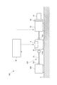
- the figure which shows typically the whole structure of the electric motor test system of this embodiment The figure which shows typically the whole structure of the electric motor test system of deformation
- the electric motor test system 100 tests the operation performance of the electric motor 200 of an electric vehicle or a hybrid vehicle on a test bench, and is connected to the electric motor 200 as shown in FIG.
- the electric motor 200 and the dynamometer 10 are mounted and fixed on, for example, a floor or a table X.
- the dynamometer 10 performs a test operation of the electric motor 200.
- the dynamometer 10 functions as a drive device that drives the electric motor 200 by operating as an electric motor according to the test operation state, and operates as an electric motor by operating as a generator. It functions as a load device that applies a load to 200.
- the dynamometer 10 is, for example, an AC electric dynamometer including an electric motor that is an AC motor (not shown). In the present embodiment, as shown in FIG. It is of a both-end drive type configured to be able to output power from the end side 11b.
- connection mechanism 20 mechanically connects the rotating shaft 201 of the electric motor 200 and the rotating shaft 11 of the dynamometer 10, specifically, the rotating shaft 201 of the electric motor 200 and the rotating shaft of the dynamometer 10.
- 11 is a shaft connected to one end side 11a, a coupling connecting the shaft and the rotating shaft 201, a coupling connecting the shaft and the one end side 11a, and the like.
- a gear or the like may be used as the connection mechanism 20.
- the rotation transmission system 300 includes the rotation shaft 201 of the electric motor 200, the rotation shaft 11 of the dynamometer 10, and the connection mechanism 20 that connects the electric motor 200 and the dynamometer 10. Further, it further has a connection mechanism such as a shaft or a coupling connected to the other end side 11b of the rotating shaft 11 of the dynamometer 10.
- the torque sensor 30 is connected to the rotation transmission system 300, measures the torque of the electric motor 200, and outputs a measurement signal indicating the measured value to the control device 40.
- a flange type sensor is used. Is used.
- various types such as a contact type or a non-contact type may be used.
- the control device 40 receives the measurement signal from the torque sensor 30 described above, calculates a load applied to the electric motor 200 based on the torque indicated by the measurement signal, and the electric motor 200 is in a predetermined test operation state. Thus, the dynamometer 10 is controlled.
- the electric motor test system 100 of the present embodiment is detachably connected to the rotation transmission system 300 described above in order to measure the cogging torque of the electric motor 200.
- a cogging torque measuring motor 50 that rotates the rotation shaft 201 to generate cogging torque is further provided.
- the cogging torque measuring motor 50 is fixed to the base X and is provided closer to the dynamometer 10 than the torque sensor 30 described above via the contact / separation mechanism 60 and the speed reducer 70.
- the cogging torque measuring motor 50 is connected to the other end 11b of the rotating shaft 11 of the dynamometer 10 described above.
- the rotating shaft 201 of the electric motor 200 is rotated at a predetermined rotational speed. This is a low rotation motor that rotates at a low speed.
- the cogging torque measuring motor 50 may be one that controls the angle of the rotating shaft 201 of the electric motor 200.
- the cogging torque measuring motor 50 includes a motor configured to alternately repeat a rotating state in which the rotating shaft 201 is rotated by a predetermined angle and a stopped state in which the rotating shaft 201 is stopped for a predetermined time.
- the contact / separation mechanism 60 is provided between the cogging torque measuring motor 50 and the dynamometer 10, receives a control signal from the control device 40, and sends the cogging torque measuring motor 50 to the rotation transmission system 300.
- the connection state is switched to the connection state and the non-connection state in which the cogging torque measurement motor 50 is disconnected from the rotation transmission system 300.
- the contact / separation mechanism 60 of the present embodiment is connected to the other end side 11b of the rotating shaft 11 of the dynamometer 10 through a shaft.
- the contact / separation mechanism 60 is configured using a clutch mechanism such as an electromagnetic clutch. It is.
- the speed reducer 70 decelerates the rotational speed of the cogging torque measuring motor 50 by a predetermined speed reduction ratio (for example, 1/100 or 1/1000).
- the speed reducer 70 is placed on the table X. It is fixed and provided between the cogging torque measuring motor 50 and the contact / separation mechanism 60. With the arrangement described above, the contact / separation mechanism 60 is provided between the dynamometer 10 and the speed reducer 70, and the speed reducer 70 can be connected to or disconnected from the rotation transmission system 300 together with the cogging torque measuring motor 50. it can.
- the rotation transmission system 300 and the cogging torque measuring motor 50 are fixedly arranged on the table X so that the axes of these rotation axes coincide.
- the contact / separation mechanism 60 receives a control signal from the control device 40 and enters a connected state, and connects the cogging torque measuring motor 50 to the rotation transmission system 300.
- the dynamometer 10 With setting the dynamometer 10 to a no-load state, the dynamometer 10 becomes free, and the cogging torque measuring motor 50 rotates the electric motor 200 at a low speed.
- the torque sensor 30 measures the torque generated when the cogging torque measuring motor 50 rotates the electric motor 200, and outputs a measurement signal indicating the measured torque to the control device 40.
- the control apparatus 40 can acquire the torque indicated by the measurement signal as the cogging torque of the electric motor 200.
- the cogging torque measuring motor 50 and the rotation transmission system 300 are fixedly disposed in advance on the table X so that the axes of the rotation axes coincide with each other. Therefore, when the contact / separation mechanism 60 is switched, misalignment such as centering is not likely to occur. Thus, the cogging torque can be easily and accurately measured by switching the contact / separation mechanism 60 to the connected state and connecting the cogging torque measuring motor 50 to the rotation transmission system 300.
- the cogging torque measurement motor 50 is disconnected from the rotation transmission system 300 so that the rotation of the dynamometer 10 is not transmitted to the cogging torque measurement motor 50 and the cogging torque measurement is performed. It is possible to prevent the motor 50 from rotating at a high speed and being damaged.
- the electric motor test system 100 includes the speed reducer 70 that reduces the rotational speed of the cogging torque measuring motor 50, the low rotational performance required for the cogging torque measuring motor 50 can be reduced. it can.
- the contact / separation mechanism 60 is provided between the speed reducer 70 and the dynamometer 10. And the rotation transmission system 300 can be separated so that the rotation of the dynamometer 10 is not transmitted to the speed reducer 70, and there is no possibility of damaging the speed reducer 70.
- the torque sensor 30 is provided between the shaft and the one end side 11a of the rotating shaft 11 of the dynamometer 10, a dedicated component for attaching the torque sensor 30 to the shaft or the like is not required, and the configuration Can be simplified.
- the present invention is not limited to the above embodiment.
- the cogging torque measuring motor 50 is connected to the other end 11b of the rotating shaft 11 of the dynamometer 10 via the contact / separation mechanism 60 and the speed reducer 70, but as shown in FIG.
- the cogging torque measuring motor 50 may be connected to the one end side 11 a of the rotating shaft 11 of the dynamometer 10 via the contact / separation mechanism 60 and the speed reducer 70.
- the contact / separation mechanism 60 is connected to the connection mechanism 20 (specifically, a shaft) via a bevel gear 80 or the like, for example.
- the torque sensor 30 provided in the connection mechanism 20 only needs to be positioned closer to the electric motor 200 than the connection point between the connection mechanism 20 and the contact / separation mechanism 60.
- the contact / separation mechanism 60 of the above embodiment is provided between the dynamometer 10 and the speed reducer 70.
- the contact / separation mechanism 60 measures the cogging torque with the speed reducer 70, for example, as shown in FIG.
- the motor 50 may be provided.
- the torque sensor 30 of the above-described embodiment is a fixed type, for example, a swing type attached to the dynamometer 10 may be used.
- the dynamometer 10 of the above embodiment uses an AC type, for example, a DC type may be used.
- the contact / separation mechanism 60 of the embodiment has a clutch mechanism such as an electromagnetic clutch.
- the contact / separation mechanism 60 is not limited to the electromagnetic clutch, and the cogging torque measuring motor 50 is mechanically connected from the rotation transmission system 300 or Anything that can be separated is acceptable.
- contact / separation mechanism 60 and the speed reducer 70 of the above-described embodiment are not necessarily provided.
- the electric motor 200 may be in a no-load state.
- the torque sensor 30 may be provided between the dynamometer 10 and the cogging torque measuring motor 50.
- the above-described embodiment can be similarly applied to the electric motor test system 100 shown in FIG.
- the electric motor test system 100 of the embodiment may test the performance of the electric motor mounted on the fuel cell vehicle (FCV).
- FCV fuel cell vehicle
- the present invention it is possible to easily and accurately measure the cogging torque of the electric motor without moving the electric motor, eliminating the need for alignment such as centering that was conventionally required for each measurement of the cogging torque. be able to.
Landscapes
- Physics & Mathematics (AREA)
- General Physics & Mathematics (AREA)
- Engineering & Computer Science (AREA)
- Chemical & Material Sciences (AREA)
- Combustion & Propulsion (AREA)
- Manufacturing & Machinery (AREA)
- Power Engineering (AREA)
- Force Measurement Appropriate To Specific Purposes (AREA)
- Testing Of Devices, Machine Parts, Or Other Structures Thereof (AREA)
- Manufacture Of Motors, Generators (AREA)
Abstract
Description
より具体的には、実際の運転状態を模擬すべく、電動モータとダイナモメータとの間に生じるトルクを測定し、この測定値に基づいて必要な負荷などを判断して、ダイナモメータを制御するようにしている。
さらにその際、芯出し等にミスアライメントが生じると、その影響でコギングトルクを正確に測定することができないという問題も生じ得る。
ここで、例えば、電動モータとダイナモメータとを接続するシャフトにコギングトルク測定用モータを接続する場合、この接続箇所にかさ歯車などを用いる必要がある。一方、上述した構成であれば、コギングトルク測定用モータをダイナモメータに簡易な構成で接続することができる。
この場合、上述したようにかさ歯車などを用いる必要はあるが、電動モータ試験システムを設置するスペースが、電動モータやダイナモメータの回転軸方向に限られている場合には有利である。
これならば、トルクセンサにより測定される測定トルクが、コギングトルク測定用モータの回転が電動モータに伝達されている状態では、コギングトルクとして測定され、ダイナモメータの回転が電動モータに伝達されている状態では、電動モータの性能試験に用いられる通常試験用トルクとして測定される。つまり、トルクセンサをコギングトルクの測定と通常試験用トルクの測定とに兼用することができ、コギングトルクを測定するための専用のトルクセンサは不要である。
これならば、コギングトルク測定用モータは高速で回転すると破損する恐れがあるところ、通常試験時に、コギングトルク測定用モータをダイナモメータから切り離すことで、ダイナモメータの高速な回転をコギングトルク測定用モータに伝わらないようにすることができ、コギングトルク測定用モータの破損を防ぐことができる。
これならば、コギングトルク測定用モータに必要とされる低回転性能における回転安定性を向上させることができる。
200・・・電動モータ
10 ・・・ダイナモメータ
20 ・・・接続機構
300・・・回転伝達系
30 ・・・トルクセンサ
50 ・・・コギングトルク測定用モータ
60 ・・・接離機構
なお、本実施形態では、電動モータ200及びダイナモメータ10は、例えば床や台X上に載置されて固定されている。
具体的にこのダイナモメータ10は、例えば、図示しない交流モータたる電動モータを備えた交流式電気動力計であり、本実施形態では、図1に示すように、回転軸11の一端側11a及び他端側11bから動力を出力できるように構成された両端駆動式のものである。
なお、トルクセンサ30としては、例えば接触式或いは非接触式など、種々のタイプのものを用いても構わない。
なお、コギングトルク測定用モータ50は、電動モータ200の回転軸201を角度制御するものであっても良い。この場合、コギングトルク測定用モータ50としては、前記回転軸201を所定角度回転させる回転状態と、前記回転軸201を所定時間停止させる停止状態とを交互に繰り返すように構成されたものが挙げられる。
上述した配置により、接離機構60は、ダイナモメータ10と減速機70との間に設けられることになり、コギングトルク測定用モータ50とともに減速機70を回転伝達系300に接続する又は切り離すことができる。
通常試験時は、接離機構60が制御装置40からの制御信号を受け付けて非接続状態となり、コギングトルク測定用モータ50を回転伝達系300から切り離す。なお、このとき、コギングトルク測定用モータの電源はオフにしておくことが好ましい。
この非接続状態において、トルクセンサ30は、電動モータ200とダイナモメータ10との間に生じるトルクを測定し、この測定トルクを示す測定信号を制御装置40に出力する。
制御装置40は、前記測定信号が示すトルクを通常試験トルクとして取得し、前記通常試験トルクに基づいて、ダイナモメータ10を制御して駆動装置或いは負荷装置として機能させる。
これにより電動モータ200を所定の運転試験状態にして、該電動モータ200の動作性能を試験することができる。
コギングトルク測定時は、接離機構60が制御装置40からの制御信号を受け付けて接続状態となり、コギングトルク測定用モータ50を回転伝達系300に接続する。
この接続状態において、ダイナモメータ10を無負荷状態にすることにより、該ダイナモメータ10はフリーになっており、コギングトルク測定用モータ50が電動モータ200を低速度で回転させる。
このとき、トルクセンサ30は、コギングトルク測定用モータ50が電動モータ200を回転させることにより発生するトルクを測定し、この測定トルクを示す測定信号を制御装置40に出力する。
これにより、制御装置40は、前記測定信号が示すトルクを電動モータ200のコギングトルクとして取得することができる。
そのうえ、電動モータ200の性能を試験する通常試験時は、コギングトルク測定用モータ50を回転伝達系300から切り離すことで、ダイナモメータ10の回転がコギングトルク測定用モータ50に伝わらず、コギングトルク測定用モータ50が高速で回転して破損することを防ぐことができる。
具体的には、接離機構60が、図2に示すように、例えばかさ歯車80等を介して、接続機構20(具体的には、シャフト)に接続される構成が挙げられる。
この場合、接続機構20に設けられたトルクセンサ30は、接続機構20と接離機構60との接続箇所より、電動モータ200側に位置していれば良い。
なお、上述した実施態様は、図2に示す電動モータ試験システム100に関しても同様に適用することができる。
Claims (6)
- 自動車の電動モータの性能を試験する電動モータ試験システムであって、
前記電動モータに接続されたダイナモメータと、
前記電動モータのトルクを測定するトルクセンサと、
前記電動モータのコギングトルクを測定するためのコギングトルク測定用モータとを具備し、
前記電動モータのコギングトルク測定時に、前記電動モータと前記ダイナモメータと前記コギングトルク測定用モータとが接続されていることを特徴とする電動モータ試験システム。 - 前記電動モータが、前記ダイナモメータの回転軸の一端側に接続されており、
前記コギングトルク測定用モータが、前記回転軸の他端側に接続されていることを特徴とする請求項1記載の電動モータ試験システム。 - 前記電動モータが、前記ダイナモメータの回転軸の一端側に接続されており、
前記コギングトルク測定用モータが、前記回転軸の一端側又はこれに前記電動モータを接続する接続機構に接続されていることを特徴とする請求項1記載の電動モータ試験システム。 - 前記トルクセンサが、前記コギングトルク測定用モータよりも前記電動モータ側に設けられていることを特徴とする請求項1記載の電動モータ試験システム。
- 前記コギングトルク測定用モータと前記ダイナモメータとの間に設けられた接離機構をさらに具備し、
前記接離機構が、
前記電動モータのコギングトルク測定時に、前記コギングトルク測定用モータを前記ダイナモメータに接続し、
前記電動モータの性能を試験する通常試験時に、前記コギングトルク測定用モータを前記ダイナモメータから切り離すことを特徴とする請求項1記載の電動モータ試験システム。 - 前記コギングトルク測定用モータに接続され、前記コギングトルク測定用モータの回転速度を減速させる減速機を具備していることを特徴とする請求項1記載の電動モータ試験システム。
Priority Applications (4)
| Application Number | Priority Date | Filing Date | Title |
|---|---|---|---|
| CN201580026558.XA CN106461505B (zh) | 2014-09-03 | 2015-08-21 | 电动马达测试系统 |
| US15/313,747 US10295437B2 (en) | 2014-09-03 | 2015-08-21 | Electric motor test system |
| JP2016546418A JP6588442B2 (ja) | 2014-09-03 | 2015-08-21 | 電動モータ試験システム |
| EP15837808.3A EP3190397B1 (en) | 2014-09-03 | 2015-08-21 | Electric motor test system |
Applications Claiming Priority (2)
| Application Number | Priority Date | Filing Date | Title |
|---|---|---|---|
| JP2014179506 | 2014-09-03 | ||
| JP2014-179506 | 2014-09-03 |
Publications (1)
| Publication Number | Publication Date |
|---|---|
| WO2016035575A1 true WO2016035575A1 (ja) | 2016-03-10 |
Family
ID=55439641
Family Applications (1)
| Application Number | Title | Priority Date | Filing Date |
|---|---|---|---|
| PCT/JP2015/073517 Ceased WO2016035575A1 (ja) | 2014-09-03 | 2015-08-21 | 電動モータ試験システム |
Country Status (5)
| Country | Link |
|---|---|
| US (1) | US10295437B2 (ja) |
| EP (1) | EP3190397B1 (ja) |
| JP (1) | JP6588442B2 (ja) |
| CN (1) | CN106461505B (ja) |
| WO (1) | WO2016035575A1 (ja) |
Cited By (3)
| Publication number | Priority date | Publication date | Assignee | Title |
|---|---|---|---|---|
| CN106840679A (zh) * | 2017-03-22 | 2017-06-13 | 中国汽车技术研究中心 | 一种测试电机堵转性能实验的系统 |
| JP2019184506A (ja) * | 2018-04-16 | 2019-10-24 | 日章電機株式会社 | モータのトルク変動計測装置および計測方法 |
| JP2019537024A (ja) * | 2016-12-05 | 2019-12-19 | ツェットエフ、フリードリッヒスハーフェン、アクチエンゲゼルシャフトZf Friedrichshafen Ag | 電気自動車駆動装置用のモジュール構成可能なドライブトレイン試験台 |
Families Citing this family (10)
| Publication number | Priority date | Publication date | Assignee | Title |
|---|---|---|---|---|
| JP6505414B2 (ja) * | 2014-10-31 | 2019-04-24 | 株式会社東芝 | 電動車両用試験装置および方法 |
| JP6467209B2 (ja) * | 2014-12-09 | 2019-02-06 | オークマ株式会社 | 電動機のコギングトルク測定方法 |
| CN108845259B (zh) * | 2018-07-17 | 2020-12-11 | 芜湖固高自动化技术有限公司 | 一种电机测试与控制系统平台 |
| CN109855876A (zh) * | 2018-12-24 | 2019-06-07 | 重庆优摩特科技有限公司 | 用于发动机功率检测的方法及其装置 |
| CN109556866A (zh) * | 2019-01-19 | 2019-04-02 | 南通远辰测控设备有限公司 | 电动机测试装置 |
| AT523676B1 (de) | 2020-04-07 | 2022-01-15 | Tectos Gmbh | Mess- und prüfeinrichtung für schnelldrehende elektrische maschinen |
| KR102667285B1 (ko) * | 2021-09-14 | 2024-05-20 | 이레산업(주) | 모터 다이나모미터 및 모터 특성 곡선 생성 방법 |
| CN114112135A (zh) * | 2021-11-05 | 2022-03-01 | 格力电器(武汉)有限公司 | 一种步进电机转矩自动测试装置及测试系统 |
| CN115219084B (zh) * | 2022-05-23 | 2024-08-09 | 阿尔特汽车技术股份有限公司 | 电机齿槽转矩的测试方法、装置及计算机可读存储介质 |
| CN115371864A (zh) * | 2022-09-20 | 2022-11-22 | 柳州赛克科技发展有限公司 | 一种混动电机扭矩测试方法及其测试台架 |
Citations (3)
| Publication number | Priority date | Publication date | Assignee | Title |
|---|---|---|---|---|
| JP2000035380A (ja) * | 1998-07-15 | 2000-02-02 | Shinko Electric Co Ltd | ハイブリッド電気自動車用試験装置 |
| JP2009042137A (ja) * | 2007-08-10 | 2009-02-26 | Jtekt Corp | コギングトルク異常検査方法及び電動パワーステアリング装置の製造方法 |
| WO2013186871A1 (ja) * | 2012-06-13 | 2013-12-19 | 三菱電機株式会社 | 回転機のコギングトルク測定装置 |
Family Cites Families (14)
| Publication number | Priority date | Publication date | Assignee | Title |
|---|---|---|---|---|
| US2520696A (en) * | 1946-03-13 | 1950-08-29 | Electric Products Company | Dynamometer |
| JPH06109565A (ja) * | 1992-09-29 | 1994-04-19 | Canon Inc | モータのコギングトルク測定装置及び測定方法 |
| DE10333397B4 (de) * | 2003-07-16 | 2005-06-30 | Minebea Co., Ltd. | Drehmoment-Meßvorrichtung für Elektromotoren |
| TWM275408U (en) | 2004-12-07 | 2005-09-11 | Kuo-Hua Hung | A cogging torque measuring device of permanent-magnet machines |
| JP2006220497A (ja) | 2005-02-09 | 2006-08-24 | Asmo Co Ltd | コギングトルク測定装置及びコギングトルクの測定方法 |
| CN101000281A (zh) * | 2006-12-28 | 2007-07-18 | 奇瑞汽车有限公司 | 混合动力电动汽车动力总成台架实验装置 |
| US7755310B2 (en) | 2007-09-11 | 2010-07-13 | Gm Global Technology Operations, Inc. | Method and apparatus for electric motor torque monitoring |
| US20090125171A1 (en) | 2007-11-08 | 2009-05-14 | Gm Global Technology Operations, Inc. | Processor security diagnostics for hybrid vehicle electric motor control system |
| JP5255345B2 (ja) | 2008-07-03 | 2013-08-07 | アスモ株式会社 | コギングトルクの測定方法及びコギングトルク測定装置 |
| CN101753073B (zh) | 2008-12-20 | 2012-03-14 | 鸿富锦精密工业(深圳)有限公司 | 马达的齿槽定位转矩补偿系统及方法 |
| US9086333B2 (en) | 2011-06-16 | 2015-07-21 | Horiba Instruments Incorporated | Examination system for electric vehicle or hybrid electric vehicle |
| CN102937699B (zh) * | 2011-12-23 | 2015-06-03 | 同济大学 | 分布式驱动用轮毂电机高频转矩波动测试系统 |
| US9205556B1 (en) * | 2013-06-24 | 2015-12-08 | Redwood Robotics, Inc. | Cogging torque measurement for a robot actuator |
| CN103808444B (zh) * | 2014-02-14 | 2017-01-11 | 奇瑞新能源汽车技术有限公司 | 一种永磁同步电机齿槽转矩的测量系统 |
-
2015
- 2015-08-21 US US15/313,747 patent/US10295437B2/en active Active
- 2015-08-21 WO PCT/JP2015/073517 patent/WO2016035575A1/ja not_active Ceased
- 2015-08-21 EP EP15837808.3A patent/EP3190397B1/en active Active
- 2015-08-21 JP JP2016546418A patent/JP6588442B2/ja active Active
- 2015-08-21 CN CN201580026558.XA patent/CN106461505B/zh active Active
Patent Citations (3)
| Publication number | Priority date | Publication date | Assignee | Title |
|---|---|---|---|---|
| JP2000035380A (ja) * | 1998-07-15 | 2000-02-02 | Shinko Electric Co Ltd | ハイブリッド電気自動車用試験装置 |
| JP2009042137A (ja) * | 2007-08-10 | 2009-02-26 | Jtekt Corp | コギングトルク異常検査方法及び電動パワーステアリング装置の製造方法 |
| WO2013186871A1 (ja) * | 2012-06-13 | 2013-12-19 | 三菱電機株式会社 | 回転機のコギングトルク測定装置 |
Non-Patent Citations (1)
| Title |
|---|
| See also references of EP3190397A4 * |
Cited By (5)
| Publication number | Priority date | Publication date | Assignee | Title |
|---|---|---|---|---|
| JP2019537024A (ja) * | 2016-12-05 | 2019-12-19 | ツェットエフ、フリードリッヒスハーフェン、アクチエンゲゼルシャフトZf Friedrichshafen Ag | 電気自動車駆動装置用のモジュール構成可能なドライブトレイン試験台 |
| JP7057359B2 (ja) | 2016-12-05 | 2022-04-19 | ツェットエフ、フリードリッヒスハーフェン、アクチエンゲゼルシャフト | 電気自動車駆動装置用のモジュール構成可能なドライブトレイン試験台 |
| CN106840679A (zh) * | 2017-03-22 | 2017-06-13 | 中国汽车技术研究中心 | 一种测试电机堵转性能实验的系统 |
| CN106840679B (zh) * | 2017-03-22 | 2023-10-24 | 中国汽车技术研究中心 | 一种测试电机堵转性能实验的系统 |
| JP2019184506A (ja) * | 2018-04-16 | 2019-10-24 | 日章電機株式会社 | モータのトルク変動計測装置および計測方法 |
Also Published As
| Publication number | Publication date |
|---|---|
| EP3190397A4 (en) | 2018-04-18 |
| CN106461505A (zh) | 2017-02-22 |
| JP6588442B2 (ja) | 2019-10-09 |
| EP3190397A1 (en) | 2017-07-12 |
| CN106461505B (zh) | 2019-11-19 |
| US10295437B2 (en) | 2019-05-21 |
| JPWO2016035575A1 (ja) | 2017-06-15 |
| EP3190397B1 (en) | 2020-02-12 |
| US20170191903A1 (en) | 2017-07-06 |
Similar Documents
| Publication | Publication Date | Title |
|---|---|---|
| JP6588442B2 (ja) | 電動モータ試験システム | |
| CN104697789A (zh) | 混合动力变速器下线检测装置 | |
| CN110036270B (zh) | 用于电的机动车驱动器的能模块化构建的驱动系测试台 | |
| CN102096043B (zh) | 一种电机寿命测试平台及测试方法 | |
| TW201818639A (zh) | 馬達單元、動力模擬器、扭力測試裝置、轉動扭力測試裝置、線性致動器及勵磁裝置 | |
| CN104502106A (zh) | 一种混合动力汽车动力总成试验台 | |
| CN107655688A (zh) | 一种rv减速器综合检测装置 | |
| CN110793690B (zh) | 一种在混合动力总成台架上测试电机效率的方法 | |
| JP2010071864A (ja) | カップリング試験装置及び方法 | |
| CN105548880A (zh) | 一种多功能通用电机测试台 | |
| CN113551917B (zh) | 一种燃气轮机多机并车装置半物理仿真试验台及试验方法 | |
| CN207611282U (zh) | 一种用于新能源汽车电机控制器的跑合试验台 | |
| CN102175451B (zh) | 联轴器动载试验台 | |
| CN103499791A (zh) | 电机综合测试平台 | |
| WO2009129682A1 (zh) | 一种混合动力控制器的测试系统 | |
| CN101598615B (zh) | 小型外转子发电机的功率测试装置 | |
| CN103884459B (zh) | 一种测功设备 | |
| CN103851100A (zh) | 超越离合器工作状态的监测结构及工程机械 | |
| CN106441878A (zh) | 一种双速传动验证装置 | |
| CN201417288Y (zh) | 小型外转子发电机的功率测试装置 | |
| CN107806994A (zh) | 一种动态扭矩试验台 | |
| CN104634573B (zh) | 一种用于双电机同轴冗余驱动控制研究的实验台 | |
| CN203798479U (zh) | 具有震动消除功能的扭力测试仪 | |
| CN106644752A (zh) | 一种利用双惯量盘进行转动轴破坏性试验的方法及其装置 | |
| CN204269784U (zh) | 一种电机检测装置 |
Legal Events
| Date | Code | Title | Description |
|---|---|---|---|
| 121 | Ep: the epo has been informed by wipo that ep was designated in this application |
Ref document number: 15837808 Country of ref document: EP Kind code of ref document: A1 |
|
| ENP | Entry into the national phase |
Ref document number: 2016546418 Country of ref document: JP Kind code of ref document: A |
|
| REEP | Request for entry into the european phase |
Ref document number: 2015837808 Country of ref document: EP |
|
| WWE | Wipo information: entry into national phase |
Ref document number: 15313747 Country of ref document: US Ref document number: 2015837808 Country of ref document: EP |
|
| NENP | Non-entry into the national phase |
Ref country code: DE |