WO2016035646A1 - 光変調装置および光学システム - Google Patents
光変調装置および光学システム Download PDFInfo
- Publication number
- WO2016035646A1 WO2016035646A1 PCT/JP2015/074079 JP2015074079W WO2016035646A1 WO 2016035646 A1 WO2016035646 A1 WO 2016035646A1 JP 2015074079 W JP2015074079 W JP 2015074079W WO 2016035646 A1 WO2016035646 A1 WO 2016035646A1
- Authority
- WO
- WIPO (PCT)
- Prior art keywords
- light
- modulated
- output
- polarization
- unit
- Prior art date
- Legal status (The legal status is an assumption and is not a legal conclusion. Google has not performed a legal analysis and makes no representation as to the accuracy of the status listed.)
- Ceased
Links
Images


Classifications
-
- G—PHYSICS
- G02—OPTICS
- G02F—OPTICAL DEVICES OR ARRANGEMENTS FOR THE CONTROL OF LIGHT BY MODIFICATION OF THE OPTICAL PROPERTIES OF THE MEDIA OF THE ELEMENTS INVOLVED THEREIN; NON-LINEAR OPTICS; FREQUENCY-CHANGING OF LIGHT; OPTICAL LOGIC ELEMENTS; OPTICAL ANALOGUE/DIGITAL CONVERTERS
- G02F1/00—Devices or arrangements for the control of the intensity, colour, phase, polarisation or direction of light arriving from an independent light source, e.g. switching, gating or modulating; Non-linear optics
- G02F1/01—Devices or arrangements for the control of the intensity, colour, phase, polarisation or direction of light arriving from an independent light source, e.g. switching, gating or modulating; Non-linear optics for the control of the intensity, phase, polarisation or colour
- G02F1/13—Devices or arrangements for the control of the intensity, colour, phase, polarisation or direction of light arriving from an independent light source, e.g. switching, gating or modulating; Non-linear optics for the control of the intensity, phase, polarisation or colour based on liquid crystals, e.g. single liquid crystal display cells
-
- G—PHYSICS
- G02—OPTICS
- G02B—OPTICAL ELEMENTS, SYSTEMS OR APPARATUS
- G02B27/00—Optical systems or apparatus not provided for by any of the groups G02B1/00 - G02B26/00, G02B30/00
- G02B27/28—Optical systems or apparatus not provided for by any of the groups G02B1/00 - G02B26/00, G02B30/00 for polarising
- G02B27/283—Optical systems or apparatus not provided for by any of the groups G02B1/00 - G02B26/00, G02B30/00 for polarising used for beam splitting or combining
-
- G—PHYSICS
- G01—MEASURING; TESTING
- G01J—MEASUREMENT OF INTENSITY, VELOCITY, SPECTRAL CONTENT, POLARISATION, PHASE OR PULSE CHARACTERISTICS OF INFRARED, VISIBLE OR ULTRAVIOLET LIGHT; COLORIMETRY; RADIATION PYROMETRY
- G01J1/00—Photometry, e.g. photographic exposure meter
- G01J1/02—Details
- G01J1/04—Optical or mechanical part supplementary adjustable parts
- G01J1/0407—Optical elements not provided otherwise, e.g. manifolds, windows, holograms, gratings
- G01J1/0429—Optical elements not provided otherwise, e.g. manifolds, windows, holograms, gratings using polarisation elements
-
- G—PHYSICS
- G01—MEASURING; TESTING
- G01J—MEASUREMENT OF INTENSITY, VELOCITY, SPECTRAL CONTENT, POLARISATION, PHASE OR PULSE CHARACTERISTICS OF INFRARED, VISIBLE OR ULTRAVIOLET LIGHT; COLORIMETRY; RADIATION PYROMETRY
- G01J1/00—Photometry, e.g. photographic exposure meter
- G01J1/42—Photometry, e.g. photographic exposure meter using electric radiation detectors
- G01J1/44—Electric circuits
-
- G—PHYSICS
- G02—OPTICS
- G02B—OPTICAL ELEMENTS, SYSTEMS OR APPARATUS
- G02B5/00—Optical elements other than lenses
- G02B5/08—Mirrors
-
- G—PHYSICS
- G02—OPTICS
- G02F—OPTICAL DEVICES OR ARRANGEMENTS FOR THE CONTROL OF LIGHT BY MODIFICATION OF THE OPTICAL PROPERTIES OF THE MEDIA OF THE ELEMENTS INVOLVED THEREIN; NON-LINEAR OPTICS; FREQUENCY-CHANGING OF LIGHT; OPTICAL LOGIC ELEMENTS; OPTICAL ANALOGUE/DIGITAL CONVERTERS
- G02F2203/00—Function characteristic
- G02F2203/06—Polarisation independent
-
- G—PHYSICS
- G02—OPTICS
- G02F—OPTICAL DEVICES OR ARRANGEMENTS FOR THE CONTROL OF LIGHT BY MODIFICATION OF THE OPTICAL PROPERTIES OF THE MEDIA OF THE ELEMENTS INVOLVED THEREIN; NON-LINEAR OPTICS; FREQUENCY-CHANGING OF LIGHT; OPTICAL LOGIC ELEMENTS; OPTICAL ANALOGUE/DIGITAL CONVERTERS
- G02F2203/00—Function characteristic
- G02F2203/18—Function characteristic adaptive optics, e.g. wavefront correction
Definitions
- One aspect of the present invention relates to a light modulation device and an optical system.
- the spatial light modulator has a modulation surface on which a plurality of pixels that modulate the amplitude or phase of input light and output the modulated light are arranged, and the amplitude for each pixel with respect to the input light Modulation or phase modulation can be performed to output the modulated light.
- Various configurations and applications of the spatial light modulator are known.
- the technique described in Non-Patent Document 1 is a type of spatial light modulator that uses a spatial light phase modulator (PPM: Programmable Phase Modulator) that can only perform phase modulation. It is intended to correct the aberration of the optical system.
- PPM Programmable Phase Modulator
- Non-Patent Document 1 extracts only linearly polarized light in a specific direction that can be phase-modulated in the PPM with a polarizer, and inputs the extracted linearly polarized light to the PPM.
- An object of the present invention is to provide a light modulation device capable of increasing the utilization efficiency.
- Another object of the present invention is to provide an optical system that includes such a light modulation device and can increase the light use efficiency.
- An optical modulation device includes: (1) a polarization separation unit that separates input light into linearly polarized light components in directions orthogonal to each other and outputs first separated light and second separated light; ) A first polarization plane rotating unit that rotates the polarization plane of the first separated light or the second separated light output from the polarization separating unit to make the first separated light and the second separated light linearly polarized light in the same direction; (3) having a modulation surface on which a plurality of pixels that modulate the amplitude or phase of input light and output the modulated light are arranged, the modulation surface including a first region and a second region; The first separated light out of the first separated light and the second separated light, which have been linearly polarized in the same direction by the first polarization plane rotating unit, is modulated in the first region, and the modulated first modulated light is output.
- a reflection-type spatial light modulator Modulating the second separated light in the second region and outputting the second modulated light after the modulation A reflection-type spatial light modulator, and (4) rotating the polarization plane of the first modulated light or the second modulated light output from the spatial light modulator so that the first modulated light and the second modulated light are orthogonal to each other.
- a second polarization plane rotating unit that converts linearly polarized light in an azimuth direction; and (5) combining the first modulated light and the second modulated light that have been converted into linearly polarized light in directions orthogonal to each other by the second polarization plane rotating unit, A polarization beam combining unit.
- the light input to the light modulation device having the above configuration is separated into linearly polarized light in directions orthogonal to each other by the polarization separation unit, and the first separated light and the second separated light are obtained.
- the first separated light and the second separated light are converted into linearly polarized light having the same orientation by the first polarization plane rotating unit and input to the modulation surface of the spatial light modulator.
- the amplitude or phase of the first separated light is modulated in the first region of the modulation surface of the spatial light modulator, and the first modulated light is output.
- the amplitude or phase of the second separated light is modulated in the second region of the modulation surface of the spatial light modulator, and the second modulated light is output.
- the first modulated light and the second modulated light output from the modulation surface of the spatial light modulator are converted into linearly polarized light in directions orthogonal to each other by the second polarization plane rotating unit, and synthesized by the polarization combining unit and output light. It is said.
- An optical system includes a light source that outputs light, a light modulation device configured as described above that inputs and modulates light output from the light source, outputs the modulated light, and irradiates an object. .
- light output from a light source is irradiated on an object after being modulated by a light modulation device.
- An optical system includes a light modulation device configured as described above that receives and modulates light generated by an object and outputs the modulated light, and detection that detects light output from the light modulation device. A section. In this optical system, the light generated by the object is detected by the detection unit after being modulated by the light modulation device.
- the light use efficiency can be increased.
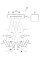
- FIG. 1 is a diagram illustrating a configuration of an optical modulation device 1A according to the first embodiment.
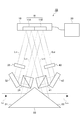
- FIG. 2 is a diagram illustrating a configuration of the light modulation device 1B according to the second embodiment.
- FIG. 3 is a diagram illustrating a configuration of an optical modulation device 1C according to the third embodiment.
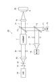
- FIG. 4 is a diagram illustrating a configuration of an optical system 2A according to the fourth embodiment.
- FIG. 5 is a diagram illustrating a configuration of an optical system 2B according to the fifth embodiment.
- FIG. 1 is a diagram illustrating a configuration of an optical modulation device 1A according to the first embodiment.
- the light modulation device 1A according to the first embodiment includes a spatial light modulator 10, a control unit 20, a polarization separation unit 31, a reflection mirror 32, a first polarization plane rotation unit 33, a polarization synthesis unit 41, a reflection mirror 42, and a second polarization.
- a surface rotation unit 43 is provided.
- the spatial light modulator 10 is of a reflective type and has a modulation surface 11 on which a plurality of pixels that modulate the amplitude or phase of input light and output the modulated light are arranged.
- the spatial light modulator 10 can perform amplitude modulation or phase modulation on the input light for each pixel and output the modulated light.
- the spatial light modulator 10 may be, for example, a spatial light modulator using an electrical address type liquid crystal element, a spatial light modulator using an optical address type liquid crystal element, a variable mirror type spatial light modulator, or the like.
- the spatial light modulator 10 may be capable of only amplitude modulation, may be capable of only phase modulation, or may be capable of both amplitude modulation and phase modulation. Good.
- the modulation surface 11 of the spatial light modulator 10 includes a first region 11A and a second region 11B.
- the first region 11 ⁇ / b> A and the second region 11 ⁇ / b> B can modulate light independently of each other based on a drive signal given from the control unit 20.
- the first region 11A receives and modulates the first separated light L11 that has arrived from the first polarization plane rotating unit 33, and outputs the modulated first modulated light L21 to the polarization combining unit 41.
- the second region 11 ⁇ / b> B receives and modulates the second separated light L ⁇ b> 12 that has arrived from the polarization separation unit 31, and outputs the modulated second modulated light L ⁇ b> 22 to the second polarization plane rotation unit 43.
- the polarization separation unit 31 receives the light Lin that is parallel light, separates the input light Lin into linearly polarized light components in directions orthogonal to each other, and outputs the first separated light L11 and the second separated light L12.
- the polarization separation unit 31 is preferably a polarization beam splitter.
- the input light Lin reflects the S-polarized component light as the first separated light L11 and transmits the P-polarized component light.
- the second separated light L12 can be obtained.
- the reflecting mirror 32 reflects the first separated light L11 reflected and output by the polarization separation unit 31 and outputs the first separated light L11 to the first polarization plane rotation unit 33.
- the first polarization plane rotating unit 33 receives the first separated light L11 that has arrived from the reflecting mirror 32, rotates the polarization plane of the first separated light L11 by 90 °, and converts the first separated light L11 into P-polarized light. To do. Accordingly, the first polarization plane rotating unit 33 can convert the first separated light L11 and the second separated light L12 into linearly polarized light (P-polarized light) having the same orientation.
- the first polarization plane rotating unit 33 is preferably a half-wave plate or a Faraday rotator.
- the first separated light L11 output from the first polarization plane rotating unit 33 and the second separated light L12 output through the polarized light separating unit 31 propagate in parallel to each other and are modulated by the spatial light modulator 10. Input to surface 11. Both the first separated light L11 and the second separated light L12 input to the modulation surface 11 of the spatial light modulator 10 are P-polarized light.
- the spatial light modulator 10 is arranged so as to be able to modulate these P-polarized light.
- the first modulated light L21 output from the first region 11A of the modulation surface 11 and the second modulated light L22 output from the second region 11B of the modulation surface 11 propagate in parallel to each other.
- the second polarization plane rotating unit 43 receives the second modulated light L22 output from the second region 11B of the modulation surface 11, and rotates the polarization plane of the second modulated light L22 by 90 ° to perform the second modulation.
- the light L22 is S-polarized light. Accordingly, the second polarization plane rotating unit 43 can convert the first modulated light L21 and the second modulated light L22 into linearly polarized light in directions orthogonal to each other.
- the second polarization plane rotating unit 43 is preferably a half-wave plate, a Faraday rotator, a prism, an optical system combining a plurality of reflecting mirrors, or the like.
- the reflecting mirror 42 reflects the second modulated light L22 output from the second polarization plane rotating unit 43 and outputs the reflected light to the polarization combining unit 41.
- the polarization beam combiner 41 receives the first modulated light L21 that has arrived from the first region 11A of the modulation surface 11 and the second modulated light L22 that has arrived from the reflecting mirror 42, and these straight lines in directions orthogonal to each other.
- the first modulated light L21 and the second modulated light L22 that are polarized light are combined to output the output light Lout.
- the polarization combiner 41 is preferably a polarization beam splitter. In this case, the P-polarized first modulated light L21 is transmitted and the S-polarized second modulated light L22 is reflected to combine the two lights. can do.
- the light modulation device 1A operates as follows.
- the light Lin input to the light modulation device 1A is separated into linearly polarized light components in directions orthogonal to each other by the polarization separation unit 31, and the first separated light L11 (S-polarized light) and the second separated light L12 (P Output as polarized light).
- the first separated light L11 (S-polarized light) output from the polarization separation unit 31 is reflected by the reflecting mirror 32, and the polarization plane is rotated by 90 ° by the first polarization plane rotation unit 33 to be P-polarized light.
- the first separated light L11 (P-polarized light) output from the first polarization plane rotating unit 33 is input to the first region 11A of the modulation surface 11 of the spatial light modulator 10, and the amplitude or phase of the first region 11A has an amplitude or phase. Modulated and output as first modulated light L21.
- the second separated light L12 (P-polarized light) output from the polarization separation unit 31 is input to the second region 11B of the modulation surface 11 of the spatial light modulator 10, and the amplitude or phase is modulated in the second region 11B.
- the second modulated light L22 is output.
- the second modulated light L22 output from the second area 11B of the modulation surface 11 is rotated by 90 ° by the second polarization surface rotation unit 43 to become S-polarized light.
- the first modulated light L21 (P-polarized light) output from the first area 11A of the modulation surface 11 and the second modulated light L22 (S-polarized light) output from the second polarization surface rotating unit 43 and reflected by the reflecting mirror 42. are synthesized by the polarization synthesis unit 41.
- the combined light Lout is output from the light modulation device 1A.
- the input light Lin is separated into linearly polarized light in directions orthogonal to each other by the polarization separation unit 31, and is used as the first separated light L11 and the second separated light L12.
- the first separated light L11 and the second separated light L12 are converted into linearly polarized light having the same orientation by the first polarization plane rotating unit 33, and input to the modulation surface 11 of the spatial light modulator 10, and the amplitude or phase is modulated.
- the first modulated light L 21 and the second modulated light L 22 output from the modulation surface 11 of the spatial light modulator 10 are converted into linearly polarized light in directions orthogonal to each other by the second polarization surface rotating unit 43, and the polarization combining unit 41. Are combined into the output light Lout.
- the light modulation device 1A has high light use efficiency.
- the light modulation device 1A has an amplitude or amplitude independent of each other with respect to the first separated light L11 and the second separated light L12 in the first region 11A and the second region 11B of the modulation surface 11 of the spatial light modulator 10, respectively. Since the phase can be modulated, not only the amplitude or phase of the input light Lin but also the polarization state can be modulated to obtain the output light Lout.
- the light modulation device 1A may further include a third polarization plane rotating unit (not shown) that rotates the polarization plane of the output light Lout. Since the polarization plane of the output light Lout may be inclined by 90 degrees with respect to the polarization plane of the input light Lin, the inclination of the polarization plane of the output light Lout is changed by the third polarization plane rotation unit. Can match. The inclination of the polarization plane of the output light Lout may be set to a desired inclination by the third polarization plane rotation unit.
- the control unit 20 may be a device dedicated to the spatial light modulator 10 or may be configured by a general-purpose device such as a computer. Further, the control unit 20 may be configured by being divided into a dedicated device and a general-purpose device.
- the controller 20 provides the spatial light modulator 10 with a drive signal for driving amplitude modulation or phase modulation in each of the plurality of pixels on the modulation surface 11 of the spatial light modulator 10.
- the control unit 20 gives a drive signal to the spatial light modulator 10 so that light can be modulated independently in each of the first region 11A and the second region 11B of the modulation surface 11 of the spatial light modulator 10.
- the drive signal given to the spatial light modulator 10 by the control unit 20 indicates the amplitude or phase modulation amount in each of the plurality of pixels on the modulation surface 11 based on the computer generated hologram displayed on the spatial light modulator 10.
- the control unit 20 includes an external input unit such as a keyboard for inputting an external signal, a calculation unit for calculating a computer hologram, a storage unit for storing the computer hologram, an external input unit, and an internal input unit.
- a selection unit that selects a computer generated hologram stored in the storage unit based on an input of a signal and the like, a drive signal is generated based on the computer hologram selected by the selection unit, and the drive signal is given to the spatial light modulator 10 And a drive unit.
- the computer hologram actually displayed on the phase modulation type spatial light modulator 10 is generated inside or outside the light modulation device 1A and the desired computer hologram representing the desired phase modulation distribution to be displayed on the spatial light modulator 10.
- a computer hologram for correction for correcting phase distortion of the wavefront of light and a computer generated hologram for intensity modulation representing a blazed grating pattern having an intensity modulation distribution corresponding to the diffraction efficiency distribution are added for each pixel. Is preferred.
- a lookup table storing the relationship between the modulation amount (phase value) in each pixel and the drive signal value is prepared in advance, and this lookup table is referred to. It is preferable to obtain a drive signal value corresponding to the modulation amount.
- the control unit 20 holds in advance a temperature information table storing the relationship between the correction computer generated hologram and the temperature, and obtains a correction computer hologram corresponding to the temperature by referring to the temperature information table. It is preferable to do this.
- a temperature information table storing the relationship between the correction computer generated hologram and the temperature
- the control unit 20 passes from the polarization separation unit 31 through the spatial light modulator 10 to the polarization combining unit 41.
- the polarization state of the output light Lout can be set by providing an additional phase difference in addition to the phase difference for correcting the phase difference due to the optical path length difference between the two optical paths.
- the additional phase difference By setting the additional phase difference to 0 or ⁇ , the output light Lout can be made into linearly polarized light.
- the output light Lout can be circularly polarized.
- the output light Lout can be elliptically polarized.
- the output light Lout is input light Lin unless amplitude modulation is performed in the first region 11A or the second region 11B of the modulation surface 11 of the spatial light modulator 10.
- the fluctuation of the intensity according to the polarization angle ⁇ of the linearly polarized light is shown. Therefore, it is desirable to correct the amplitude by the following equation for the desired intensity I of the output light Lout.
- a 1 is the amplitude of light after corrected in the first region 11A
- a 2 is the amplitude of light after corrected in the second region 11B.
- the light modulation device 1A of the present embodiment has high light use efficiency even if the spatial light modulator 10 can modulate only linearly polarized light in a specific direction. Further, in this light modulation device 1A, since the light incident / exit to the modulation surface 11 of the spatial light modulator 10 is not vertical but oblique, the light utilization efficiency is also high in this respect.
- the light modulation device 1A of the present embodiment can not only modulate the amplitude or phase of the input light Lin, but also modulate the polarization state to produce the output light Lout. Further, the light modulation device 1A can also modulate random polarized light or the like.
- the light modulation device 1A of the present embodiment uses a reflection type as the spatial light modulator 10, so that the polarization separation unit 31, the reflection mirror 32, the first polarization plane rotation unit 33, the polarization synthesis unit 41, and the reflection mirror 42 are used. And since the 2nd polarization plane rotation part 43 can be arrange
- the light modulation device 1A divides the modulation surface 11 of one spatial light modulator 10 into a first region 11A and a second region 11B and modulates light in each region. Cost reduction can be achieved. In the future, even if the number of pixels and the size of the spatial light modulator increase, the size of the light modulation device can be suppressed.
- the light modulation device 1A of the present embodiment does not need to have a mechanical movable part and is robust against vibrations.
- FIG. 2 is a diagram illustrating a configuration of the light modulation device 1B according to the second embodiment.
- the light modulation device 1B of the second embodiment further includes a light input / output unit 50 in addition to the configuration (FIG. 1) of the light modulation device 1A of the first embodiment.
- the light input / output unit 50 includes a first reflecting surface 51 and a second reflecting surface 52.
- the first reflecting surface 51 reflects the light Lin input from the outside to the polarization separation unit 31.
- the second reflecting surface 52 reflects the light Lout from the polarization beam combiner 41 and outputs it to the outside.
- the output direction of the output light Lout from the second reflective surface 52 is the same as the input direction of the input light Lin to the first reflective surface 51.
- the light input / output unit 50 includes, for example, a prism and a plurality of reflecting mirrors.
- the light modulation device 1B according to the second embodiment operates in the same manner as the light modulation device 1A according to the first embodiment and exhibits the same effects, and also has the following effects.
- the output direction of the output light Lout from the second reflecting surface 52 and the input direction of the input light Lin to the first reflecting surface 51 are parallel to each other, so that the system including the light modulation device 1B is included.
- the principal ray of the output light Lout from the second reflecting surface 52 and the principal ray of the input light Lin to the first reflecting surface 51 are on the same straight line, so that the system including the light modulation device 1B is included. Construction is even easier.
- FIG. 3 is a diagram illustrating a configuration of an optical modulation device 1C according to the third embodiment.
- the light modulation device 1C of the third embodiment includes the first polarization plane rotation unit 33 and the second polarization plane rotation unit 43, respectively.
- the spatial light modulator 10 is different so that the first separated light L11 and the second separated light L12, which are S-polarized light, can be modulated.
- the first polarization plane rotating unit 33 is provided on the optical path of the second separated light L12, and rotates the polarization plane of the second separated light L12 by 90 °. Accordingly, the first polarization plane rotating unit 33 can convert the first separated light L11 and the second separated light L12 into linearly polarized light (S-polarized light) having the same orientation.
- the second polarization plane rotating unit 43 is provided on the optical path of the first modulated light L21, and rotates the polarization plane of the first modulated light L21 by 90 °. Accordingly, the second polarization plane rotating unit 43 can convert the first modulated light L21 and the second modulated light L22 into linearly polarized light in directions orthogonal to each other.
- the light modulation device 1C operates as follows.
- the light Lin input to the light modulation device 1C is separated into linearly polarized light components in directions orthogonal to each other by the polarization separation unit 31, and the first separated light L11 (S-polarized light) and the second separated light L12 (P Output as polarized light).
- the first separated light L11 (S-polarized light) output from the polarization separation unit 31 is reflected by the reflecting mirror 32 and input to the first region 11A of the modulation surface 11 of the spatial light modulator 10, and in this first region 11A.
- the amplitude or phase is modulated and output as the first modulated light L21.
- the second separated light L12 (P-polarized light) output from the polarization separation unit 31 is rotated by 90 ° by the first polarization plane rotation unit 33 to be S-polarized light.
- the second separated light L12 (S-polarized light) output from the first polarization plane rotating unit 33 is input to the second region 11B of the modulation surface 11 of the spatial light modulator 10, and the amplitude or phase of the second region 11B has an amplitude or phase. Modulated and output as second modulated light L22.
- the first modulated light L21 output from the first region 11A of the modulation surface 11 is rotated by 90 ° by the second polarization surface rotation unit 43 to be P-polarized light.
- the first modulated light L21 (P-polarized light) output from the second polarization plane rotating unit 43, and the second modulated light L22 (S-polarized light) output from the second region 11B of the modulation surface 11 and reflected by the reflecting mirror 42 are synthesized by the polarization synthesis unit 41.
- the combined light Lout is output from the light modulation device 1C.
- the light modulation device 1C of the third embodiment has the same effects as the light modulation device 1A of the first embodiment. Also in the configuration of the light modulation device 1C according to the third embodiment, the light input / output unit 50 may be provided similarly to the light modulation device 1B according to the second embodiment.
- FIG. 4 is a diagram illustrating a configuration of an optical system 2A according to the fourth embodiment.
- the optical system 2A of the fourth embodiment irradiates the object 9 with light modulated by the light modulation device 1.
- the light modulation device 1 may be any of the light modulation devices 1A to 1C of the first to third embodiments.
- Light irradiation to the object 9 may be simple irradiation, or may be light processing or excitation of the object 9.
- the optical system 2A includes a light source 60, a lens 61, a spatial filter 62, a lens 63, an aperture 64, a light source 70, a lens 71, a beam splitter 72, a beam splitter 73, an aperture 74, a lens 75, and an aperture. 76, a lens 77, a detection unit 78, and a stage 90.
- the light source 60 outputs light to be irradiated on the object 9, and is preferably a laser light source.
- the lenses 61 and 63 receive the light output from the light source 60, expand the beam diameter, and output parallel light.
- the spatial filter 62 provided between the lens 61 and the lens 63 adjusts the intensity distribution in the beam cross section of the light, and, for example, uniformizes the light intensity in a predetermined cross-sectional area including the optical axis.
- the opening 64 inputs light output from the lens 63 and selectively outputs light in a predetermined cross-sectional area in the beam cross section of the light.
- the aperture 64 is used for aligning the optical axis, controlling the cut-out area (used when adjusting the beam aperture to the optical system, etc.), changing the beam shape (changing to an arbitrary shape such as a rectangle as well as a circle),
- the purpose is to limit the intensity distribution in advance.
- the light modulation device 1 receives and modulates the light output from the opening 64, and outputs the modulated light.
- the beam splitter 73 transmits the light modulated and output by the light modulation device 1 to the opening 74, and reflects the light output from the light source 70 and reaching the opening 74.
- the opening 74 inputs light that has arrived from the beam splitter 73 and selectively outputs light in a predetermined cross-sectional area of the beam cross section of the light, and has the same role as the opening 64.
- the lens 75 guides the light output from the opening 74 to the object 9.
- the lens 75 may condense the light output from the opening 74 on the surface or inside of the object 9, and the modulation surface 11 of the spatial light modulator 10 of the light modulation device 1 may be used as the object 75. You may image on the surface or inside.
- the light source 70 outputs light to be irradiated on the object 9 in order to observe the object 9.
- the light source 70 may be a monochromatic light source such as a laser light source or a white light source.
- the lens 71 converts the light output from the light source 70 into parallel light.
- the beam splitter 72 transmits a part of the light reaching from the lens 71 to the beam splitter 73 and reflects a part of the light reaching from the beam splitter 73 to the opening 76.
- the opening 76 inputs light that has arrived from the beam splitter 72 and selectively outputs light in a predetermined cross-sectional area in the beam cross section of the light, and has the same role as the opening 64.
- the lens 77 guides the light output from the opening 76 to the detection unit 78.
- the lens 77 may condense the light output from the opening 76 on the light receiving surface of the detection unit 78, or may form an image on the light irradiation surface of the object 9 on the light receiving surface of the detection unit 78. There may be.
- the detection unit 78 receives and detects light that has arrived from the lens 77.
- the detection unit 78 may detect the received light intensity, or may detect a one-dimensional or two-dimensional light intensity distribution.
- Stage 90 holds the object 9.
- the stage 90 is preferably capable of adjusting the position or azimuth of the object 9, and can adjust any one or more of the x-axis, y-axis, z-axis, ⁇ -axis, ⁇ -axis, and ⁇ -axis. Is preferred.
- the adjustment of the position or orientation may be based on electric power or manually.
- This optical system 2A operates as follows.
- the light output from the light source 60 is collimated by expanding the beam diameter by the lenses 61 and 63, the intensity distribution in the beam section is adjusted by the spatial filter 62, and a predetermined section of the beam section is formed by the opening 64.
- a region is selected and then input to the light modulation device 1.
- the light modulated and output by the light modulation device 1 passes through the beam splitter 73, passes through the opening 74 and the lens 75, and is collected or imaged on the object 9 held by the stage 90.
- the observation light output from the light source 70 is converted into parallel light by the lens 71, passes through the beam splitter 72, is reflected by the beam splitter 73, passes through the opening 74 and the lens 75, and is held by the stage 90. 9 is irradiated.
- the light generated in the object 9 by irradiating the object 9 with the observation light is reflected by the beam splitter 73 through the lens 75 and the aperture 74, and further reflected by the beam splitter 72.
- the light is received by the detection unit 78 through the lens 77.
- the detection unit 78 detects the intensity of the light generated in the object 9 when the object 9 is irradiated with the observation light, or detects the intensity distribution of the light generated in the object 9.
- the wavelength of light output from the light source 60 is determined by the purpose of light irradiation to the object 9, and the amplitude or phase is sufficiently modulated in the spatial light modulator 10 of the light modulation device 1. It is hoped that it can be done.
- the spatial light modulator 10 is of a phase modulation type, it is preferable that the wavelength of light output from the light source 60 can ensure a phase modulation width of ⁇ [rad] or more in the spatial light modulator 10.
- Each of the lenses 61, 63, 71, 75, 77 may be a single lens or a lens group including a plurality of lenses.
- Each of the openings 64, 74, and 76 is preferably capable of adjusting the installation position, and it is also preferable that the size and shape of the opening region can be adjusted.
- the opening may be a Fourier mask or an intensity mask having a transmittance distribution.
- An opening may be provided on the optical path in the light modulation device 1.
- an introduction position and an illumination method can be appropriately selected depending on the application and the object 9.
- a beam splitter for introducing and deriving observation light may be provided on the optical path in the light modulation device 1.
- a transmission type observation light source may be provided.
- FIG. 5 is a diagram showing a configuration of the optical system 2B of the fifth embodiment.
- the optical system 2B of the fifth embodiment detects light generated by the object 9 after it is modulated by the light modulation device 1.
- the light modulation device 1 may be any of the light modulation devices 1A to 1C of the first to third embodiments.
- the light generated by the object 9 is light (for example, transmitted light, reflected light, scattered light, fluorescence, light emission by nonlinear optical phenomenon) generated by the object 9 due to the irradiation of the object 9 with light.
- it may be light (for example, chemiluminescence) generated in the object 9 regardless of light irradiation.
- the structure detected after modulating the reflected light from the target object 9 with the light modulation apparatus 1 is demonstrated.
- the optical system 2B includes a light source 70, a lens 71, a beam splitter 73, an aperture 74, a lens 75, an aperture 76, a lens 77, a detection unit 78, and a stage 90 in addition to the light modulation device 1.
- the light source 70 outputs light to be irradiated onto the object 9.
- the light source 70 may be a monochromatic light source such as a laser light source or a white light source.
- the lens 71 converts the light output from the light source 70 into parallel light.
- the beam splitter 73 reflects a part of the light reaching from the lens 71 to the opening 74 and transmits a part of the light reaching from the opening 74 to the light modulation device 1.
- the opening 74 inputs light that has arrived from the beam splitter 73 and selectively outputs light in a predetermined cross-sectional area in the beam cross section of the light.
- the aperture 74 is used for adjusting the optical axis, controlling the cut-out area (used when adjusting the beam aperture to the optical system, etc.), changing the beam shape (changing to an arbitrary shape such as a rectangle as well as a circle), Alternatively, the purpose is to limit the intensity distribution in advance.
- the lens 75 guides the light output from the opening 74 to the object 9.
- the light modulation device 1 inputs and modulates the light generated by the object 9 and reached through the lens 75, the aperture 74, and the beam splitter 73, and outputs the modulated light.
- the opening 76 inputs light modulated and output by the light modulation device 1 and selectively outputs light in a predetermined cross-sectional area in the beam cross section of the light, and plays the same role as the opening 74.
- the lens 77 guides the light output from the opening 76 to the detection unit 78.
- the lens 77 may condense the light output from the opening 76 on the light receiving surface of the detection unit 78, or may form an image on the light irradiation surface of the object 9 on the light receiving surface of the detection unit 78. There may be.
- the detection unit 78 receives and detects light that has arrived from the lens 77.
- the detection unit 78 may detect the received light intensity, or may detect a one-dimensional or two-dimensional light intensity distribution.
- This optical system 2B operates as follows.
- the light output from the light source 70 is converted into parallel light by the lens 71, reflected by the beam splitter 73, and irradiated on the object 9 held by the stage 90 through the opening 74 and the lens 75.
- the light generated by the object 9 by irradiating the object 9 with the light passes through the lens 75 and the opening 74, passes through the beam splitter 73, and is input to the light modulation device 1.
- the light modulated and output by the light modulation device 1 is received by the detector 78 through the opening 76 and the lens 77.
- the detection unit 78 detects the intensity of light generated in the object 9 by irradiating the object 9 with light output from the light source 70 or detects the intensity distribution of light generated in the object 9. Is done.
- the wavelength of light output from the light source 70 is determined by the purpose of light irradiation to the object 9, and the amplitude or phase is sufficiently modulated in the spatial light modulator 10 of the light modulation device 1. It is hoped that it can be done.
- the spatial light modulator 10 is of the phase modulation type, it is preferable that the wavelength of light output from the light source 70 can ensure a phase modulation width of ⁇ [rad] or more in the spatial light modulator 10.
- Each of the lenses 71, 75, 77 may be a single lens or a lens system including a plurality of lenses.
- Each of the openings 74 and 76 is preferably capable of adjusting the installation position, and it is also preferable that the size and shape of the opening region can be adjusted.
- the opening may be a Fourier mask or an intensity mask having a transmittance distribution.
- An opening may be provided on the optical path in the light modulation device 1.
- an introduction position and an illumination method can be appropriately selected depending on the application and the object 9.
- a beam splitter for introducing and deriving light may be provided on the optical path in the light modulation device 1.
- a transmission type observation light source may be provided.
- the first polarization plane rotating unit 33 rotates either one of the first separated light L11 and the second separated light L12 by 90 °
- the second polarization plane rotating unit 43 One of the polarization planes of the first modulated light L21 and the second modulated light L22 is rotated by 90 °.
- the first polarization plane rotating unit 33 rotates the polarization planes of both the first separated light L11 and the second separated light L12 so that the first separated light L11 and the second separated light L12 are linearly polarized light in the same direction. It is good.
- the second polarization plane rotating unit 43 rotates the polarization planes of both the first modulated light L21 and the second modulated light L22, and the first modulated light L21 and the second modulated light L22 are straight lines having directions orthogonal to each other. It may be polarized light.
- the first polarization plane rotation unit 33 may be disposed at any position on the optical path between the modulation surface 11 of the spatial light modulator 10 and the polarization separation unit 31.
- the first polarization plane rotation unit 33 may be provided on the modulation surface 11 of the spatial light modulator 10, may be provided on the reflection surface of the reflecting mirror 32, or on the emission surface of the polarization separation unit 31. May be provided.
- the second polarization plane rotating unit 43 may be disposed at any position on the optical path between the modulation plane 11 of the spatial light modulator 10 and the polarization combining unit 41.
- the second polarization plane rotating unit 43 may be provided on the modulation surface 11 of the spatial light modulator 10, may be provided on the reflection surface of the reflecting mirror 42, or on the incident surface of the polarization beam combining unit 41. May be provided.
- Each of the polarization separation unit 31 and the polarization synthesis unit 41 is not limited to the polarization beam splitter, and may be another optical element capable of polarization separation and polarization synthesis.
- Each of the first polarization plane rotation unit 33 and the second polarization plane rotation unit 43 is not limited to a half-wave plate or a Faraday rotator, but is another optical element that can rotate the polarization plane of light. There may be.
- the observation system that observes the object 9 using the light output from the light source 70 is preferably an imaging system, and may be an imaging system including a camera lens, a microscope, or a telescope.
- Data acquired by the observation system may be any of transmission image, transmitted light intensity, fluorescence image, fluorescence intensity, emission image, emission intensity, scattered image, scattering intensity, and the like. What is necessary is just to select the wavelength of the light to observe according to the target object 9.
- a mechanism capable of changing the position of these observation systems may be attached, and may be controlled by an external signal or a feedback signal.
- the object 9 When displaying a computer generated hologram for intensity modulation representing a blazed grating pattern on the spatial light modulator 10, not only is the object 9 irradiated with the diffracted light of a specific order intensity-modulated by this blazed grating pattern, but also a specific Diffracted light of an order other than the order (including 0th order light) is also generated. Since the diffracted light of orders other than the specific order is unnecessary light, it is preferable not to irradiate the object 9 with the unnecessary light, or there is no actual harm even if the unnecessary light is irradiated to the object 9. It is preferable to do so.
- the light modulated by the spatial light modulator 10 is collected by a lens, and an opening, a knife edge, or the like is disposed in the vicinity of the condensing point of the lens.
- unnecessary light may be blocked, or light of a specific order may be selectively collimated by a 4f optical system provided at the subsequent stage of the spatial light modulator 10.
- the irradiation of the unnecessary light on the object 9 may be dispersed to reduce the energy density of the unnecessary light.
- a polarization separation unit that separates input light into linearly polarized light in directions orthogonal to each other and outputs first separated light and second separated light; and (2) polarized light.
- a first polarization plane rotating unit that rotates the polarization plane of the first separated light or the second separated light output from the separating unit so that the first separated light and the second separated light are linearly polarized light in the same direction; 3) It has a modulation surface in which a plurality of pixels that modulate the amplitude or phase of input light and output the modulated light are arranged, the modulation surface including a first region and a second region, The first separated light of the first separated light and the second separated light that have been converted to linearly polarized light in the same direction by the polarization plane rotating unit is modulated in the first region, and the modulated first modulated light is output.
- the two separated lights are modulated in the second region and the modulated second modulated light is output.
- a second polarization plane rotating unit that converts linearly polarized light in an azimuth direction; and (5) combining the first modulated light and the second modulated light that have been converted into linearly polarized light in directions orthogonal to each other by the second polarization plane rotating unit, And a polarization beam combining unit.
- the light modulation device having the above configuration includes a first reflection surface that reflects input light to the polarization separation unit, and a second reflection surface that reflects output light from the polarization combining unit, and output light from the second reflection surface. It is preferable to further include a light input / output unit whose output direction is the same as the input direction of the input light to the first reflecting surface.
- a light source that outputs light
- a light modulation device configured as described above that inputs and modulates the light output from the light source, outputs the modulated light, and irradiates the object. It is configured to provide.
- light output from a light source is irradiated on an object after being modulated by a light modulation device.
- the light modulation device configured as described above that receives and modulates light generated by an object and outputs the modulated light
- a detection unit that detects light output from the light modulation device.
- the present invention relates to a light modulation device capable of increasing light utilization efficiency even when a spatial light modulator capable of modulating only linearly polarized light in a specific direction is used, and such light.
- the present invention can be used as an optical system that includes a modulation device and can increase the light use efficiency.
- beam splitter 73 ... beam splitter , 74 ... aperture, 75 ... lens, 76 ... aperture, 77 ... lens, 78 ... detector, 90 ... stage, Lin ... input light, Lout ... output light, L11 ... first separated light, L12 ... second separated light, L21: first modulated light, L22: second modulated light.
Landscapes
- Physics & Mathematics (AREA)
- General Physics & Mathematics (AREA)
- Optics & Photonics (AREA)
- Nonlinear Science (AREA)
- Spectroscopy & Molecular Physics (AREA)
- Chemical & Material Sciences (AREA)
- Crystallography & Structural Chemistry (AREA)
- Optical Modulation, Optical Deflection, Nonlinear Optics, Optical Demodulation, Optical Logic Elements (AREA)
- Liquid Crystal (AREA)
Abstract
光変調装置1Aは、反射型空間光変調器10、偏光分離部31、第1偏光面回転部33、偏光合成部41、第2偏光面回転部43を備える。偏光分離部31は入力光Linを偏光分離して第1分離光L11(S偏光)および第2分離光L12(P偏光)を出力する。第1偏光面回転部33は第1分離光L11をP偏光とする。空間光変調器10の変調面11の第1領域11Aは第1分離光L11を変調して第1変調光L21を出力し、第2領域11Bは第2分離光L12を変調して第2変調光L22を出力する。第2偏光面回転部43は第2変調光L22をS偏光とする。偏光合成部41は第1変調光L21および第2変調光L22を偏光合成して出力光Loutを出力する。これにより、特定方位の直線偏光の光に対してのみ変調をすることができる空間光変調器を用いる場合であっても光利用効率を高くすることができる光変調装置が実現される。
Description
本発明の一側面は、光変調装置および光学システムに関するものである。
空間光変調器は、入力した光の振幅または位相を変調して当該変調後の光を出力する複数の画素が配列された変調面を有しており、入力した光に対して画素毎に振幅変調または位相変調をして当該変調後の光を出力することができる。空間光変調器の構成や用途として様々な態様のものが知られている。例えば、非特許文献1に記載された技術は、空間光変調器の一種であって位相変調のみを行うことができる空間光位相変調器(PPM: Programmable Phase Modulator)を用いて、眼底測定の際の光学系の収差を補正することを意図する。
Pedro M. Prieto, Enrique J. Fernandez, Silvestre Manzanera, Pablo Artal, "Adaptive optics with a programmable phase modulator: applications in the human eye," Optics Express, Vol.12, No.17, pp.4059-4071 (2004)
空間光変調器の構成によっては、特定方位の直線偏光の光に対しては振幅変調または位相変調をすることができるものの、この特定方位に直交する方位の直線偏光の光に対しては変調をすることができない場合がある。PPMは、特定方位の直線偏光の光に対してのみ位相変調をすることができる。それ故、非特許文献1に記載された技術は、PPMにおいて位相変調をすることができる特定方位の直線偏光の光のみを偏光子により抽出して、その抽出した直線偏光の光をPPMに入力させる。
このように特定方位の直線偏光の光に対してのみ変調をすることができる空間光変調器を用いる場合、この特定方位に直交する方位の直線偏光の光は、偏光子により遮断されて、利用されない。したがって、このような空間光変調器を用いて光の変調を行う光変調装置においては、光利用効率(変調前の光と変調後の光との強度比)は低い。
本発明の一側面は、上記問題点を解消する為になされたものであり、特定方位の直線偏光の光に対してのみ変調をすることができる空間光変調器を用いる場合であっても光利用効率を高くすることができる光変調装置を提供することを目的とする。また、本発明の一側面は、このような光変調装置を備えて光利用効率を高くすることができる光学システムを提供することをも目的とする。
本発明の一側面による光変調装置は、(1)入力光を互いに直交する方位の直線偏光の光成分に分離して第1分離光および第2分離光を出力する偏光分離部と、(2)偏光分離部から出力された第1分離光または第2分離光の偏光面を回転させて、第1分離光および第2分離光を互いに同じ方位の直線偏光とする第1偏光面回転部と、(3)入力した光の振幅または位相を変調して当該変調後の光を出力する複数の画素が配列された変調面を有し、その変調面が第1領域および第2領域を含み、第1偏光面回転部により互いに同じ方位の直線偏光とされた第1分離光および第2分離光のうち第1分離光を第1領域において変調して当該変調後の第1変調光を出力し、第2分離光を第2領域において変調して当該変調後の第2変調光を出力する反射型の空間光変調器と、(4)空間光変調器から出力された第1変調光または第2変調光の偏光面を回転させて、第1変調光および第2変調光を互いに直交する方位の直線偏光とする第2偏光面回転部と、(5)第2偏光面回転部により互いに直交する方位の直線偏光とされた第1変調光および第2変調光を合成して出力光とする偏光合成部と、を備える。
上記構成の光変調装置に入力された光は、偏光分離部により互いに直交する方位の直線偏光の光に分離されて、第1分離光および第2分離光とされる。これら第1分離光および第2分離光は、第1偏光面回転部により互いに同じ方位の直線偏光とされて、空間光変調器の変調面に入力される。空間光変調器の変調面の第1領域において第1分離光の振幅または位相が変調されて第1変調光が出力される。空間光変調器の変調面の第2領域において第2分離光の振幅または位相が変調されて第2変調光が出力される。そして、空間光変調器の変調面から出力された第1変調光および第2変調光は、第2偏光面回転部により互いに直交する方位の直線偏光とされ、偏光合成部により合成されて出力光とされる。
本発明の一側面による光学システムは、光を出力する光源と、光源から出力された光を入力して変調し当該変調後の光を出力して対象物に照射する上記構成の光変調装置と、を備える。この光学システムでは、光源から出力された光は、光変調装置において変調された後に対象物に照射される。
本発明の一側面による光学システムは、対象物で発生した光を入力して変調し当該変調後の光を出力する上記構成の光変調装置と、光変調装置から出力された光を検出する検出部と、を備える。この光学システムでは、対象物で発生した光は、光変調装置において変調された後に検出部により検出される。
本発明の一側面によれば、特定方位の直線偏光の光に対してのみ変調をすることができる空間光変調器を用いる場合であっても光利用効率を高くすることができる。
以下、添付図面を参照して、本発明を実施するための形態を詳細に説明する。なお、図面の説明において同一の要素には同一の符号を付し、重複する説明を省略する。
(第1実施形態)
図1は、第1実施形態の光変調装置1Aの構成を示す図である。第1実施形態の光変調装置1Aは、空間光変調器10、制御部20、偏光分離部31、反射鏡32、第1偏光面回転部33、偏光合成部41、反射鏡42および第2偏光面回転部43を備える。
空間光変調器10は、反射型のものであって、入力した光の振幅または位相を変調して当該変調後の光を出力する複数の画素が配列された変調面11を有している。空間光変調器10は、入力した光に対して画素毎に振幅変調または位相変調をして当該変調後の光を出力することができる。空間光変調器10は、例えば、電気アドレス型液晶素子を用いた空間光変調器、光アドレス型液晶素子を用いた空間光変調器、可変鏡型空間光変調器などであってもよい。空間光変調器10は、振幅変調のみが可能なものであってもよいし、位相変調のみが可能なものであってもよいし、振幅変調および位相変調の双方が可能なものであってもよい。
空間光変調器10の変調面11は、第1領域11Aおよび第2領域11Bを含む。第1領域11Aおよび第2領域11Bは、制御部20から与えられる駆動信号に基づいて互いに独立して光を変調することができる。第1領域11Aは、第1偏光面回転部33から到達した第1分離光L11を入力して変調し、当該変調後の第1変調光L21を偏光合成部41へ出力する。第2領域11Bは、偏光分離部31から到達した第2分離光L12を入力して変調し、当該変調後の第2変調光L22を第2偏光面回転部43へ出力する。
偏光分離部31は、平行光である光Linを入力し、この入力光Linを互いに直交する方位の直線偏光の光成分に分離して第1分離光L11および第2分離光L12を出力する。偏光分離部31は、好適には偏光ビームスプリッタであり、この場合には、入力光LinのうちS偏光成分の光を反射させて第1分離光L11とし、P偏光成分の光を透過させて第2分離光L12とすることができる。反射鏡32は、偏光分離部31で反射されて出力された第1分離光L11を反射させて第1偏光面回転部33へ出力する。
第1偏光面回転部33は、反射鏡32から到達した第1分離光L11を入力し、この第1分離光L11の偏光面を90°だけ回転させて、第1分離光L11をP偏光とする。これにより、第1偏光面回転部33は、第1分離光L11および第2分離光L12を互いに同じ方位の直線偏光(P偏光)とすることができる。第1偏光面回転部33は、好適には1/2波長板やファラデーローテータ等である。
第1偏光面回転部33から出力された第1分離光L11と、偏光分離部31を透過して出力された第2分離光L12とは、互いに平行に伝搬して空間光変調器10の変調面11に入力される。空間光変調器10の変調面11に入力される第1分離光L11および第2分離光L12は共にP偏光である。空間光変調器10は、これらのP偏光の光を変調することができるように配置されている。変調面11の第1領域11Aから出力される第1変調光L21と、変調面11の第2領域11Bから出力される第2変調光L22とは、互いに平行に伝搬する。
第2偏光面回転部43は、変調面11の第2領域11Bから出力される第2変調光L22を入力し、この第2変調光L22の偏光面を90°だけ回転させて、第2変調光L22をS偏光とする。これにより、第2偏光面回転部43は、第1変調光L21および第2変調光L22を互いに直交する方位の直線偏光とすることができる。第2偏光面回転部43は、好適には1/2波長板、ファラデーローテータ、プリズム、複数の反射鏡を組み合わせた光学系等である。反射鏡42は、第2偏光面回転部43から出力された第2変調光L22を反射させて偏光合成部41へ出力する。
偏光合成部41は、変調面11の第1領域11Aから到達した第1変調光L21を入力するとともに、反射鏡42から到達した第2変調光L22を入力して、これら互いに直交する方位の直線偏光である第1変調光L21および第2変調光L22を合成して出力光Loutを出力する。偏光合成部41は、好適には偏光ビームスプリッタであり、この場合には、P偏光の第1変調光L21を透過させるとともに、S偏光の第2変調光L22を反射させて、両光を合成することができる。
この光変調装置1Aは以下のように動作する。光変調装置1Aに入力された光Linは、偏光分離部31により、互いに直交する方位の直線偏光の光成分に分離されて、第1分離光L11(S偏光)および第2分離光L12(P偏光)として出力される。
偏光分離部31から出力された第1分離光L11(S偏光)は、反射鏡32により反射され、第1偏光面回転部33により偏光面が90°だけ回転されてP偏光とされる。第1偏光面回転部33から出力された第1分離光L11(P偏光)は、空間光変調器10の変調面11の第1領域11Aに入力され、この第1領域11Aにおいて振幅または位相が変調されて、第1変調光L21として出力される。偏光分離部31から出力された第2分離光L12(P偏光)は、空間光変調器10の変調面11の第2領域11Bに入力され、この第2領域11Bにおいて振幅または位相が変調されて、第2変調光L22として出力される。
変調面11の第2領域11Bから出力された第2変調光L22は、第2偏光面回転部43により偏光面が90°だけ回転されてS偏光とされる。変調面11の第1領域11Aから出力された第1変調光L21(P偏光)と、第2偏光面回転部43から出力され反射鏡42により反射された第2変調光L22(S偏光)とは、偏光合成部41により合成される。その合成された光Loutが光変調装置1Aから出力される。
このように、光変調装置1Aでは、入力光Linは、偏光分離部31により互いに直交する方位の直線偏光の光に分離されて、第1分離光L11および第2分離光L12とされる。これら第1分離光L11および第2分離光L12は、第1偏光面回転部33により互いに同じ方位の直線偏光とされて、空間光変調器10の変調面11に入力され振幅または位相が変調される。そして、空間光変調器10の変調面11から出力された第1変調光L21および第2変調光L22は、第2偏光面回転部43により互いに直交する方位の直線偏光とされ、偏光合成部41により合成されて出力光Loutとされる。
したがって、空間光変調器10が特定方位の直線偏光の光に対してのみ変調をすることができるものであっても、この光変調装置1Aは光利用効率が高い。また、この光変調装置1Aは、空間光変調器10の変調面11の第1領域11Aおよび第2領域11Bにおいて、第1分離光L11および第2分離光L12それぞれに対して互いに独立に振幅または位相を変調することができるので、入力光Linに対して振幅または位相を変調するだけでなく偏光状態をも変調して出力光Loutとすることができる。
なお、光変調装置1Aは、出力光Loutの偏光面を回転させる第3偏光面回転部(不図示)をさらに備えてもよい。出力光Loutの偏光面は入力光Linの偏光面に対して90度傾いている場合があるので、第3偏光面回転部により出力光Loutの偏光面の傾きを入力光Linの偏光面の傾きに一致させることができる。第3偏光面回転部により出力光Loutの偏光面の傾きを所望の傾きとしてもよい。
次に、制御部20について詳細に説明する。制御部20は、空間光変調器10に専用の装置であってもよいし、コンピュータ等の汎用の装置により構成されてもよい。また、制御部20は、専用装置と汎用装置とに分割されて構成されていてもよい。制御部20は、空間光変調器10の変調面11の複数の画素それぞれにおける振幅変調または位相変調を駆動するための駆動信号を空間光変調器10に与える。制御部20は、空間光変調器10の変調面11の第1領域11Aおよび第2領域11Bそれぞれにおいて互いに独立して光を変調することができるように駆動信号を空間光変調器10に与える。
制御部20が空間光変調器10に与える駆動信号は、空間光変調器10に表示させる計算機ホログラムに基づいて、変調面11の複数の画素それぞれにおける振幅または位相の変調量を指示するものである。制御部20は、外部からの信号を入力するキーボード等の外部入力部と、計算機ホログラムの計算等を行う計算部と、計算機ホログラム等を記憶する記憶部と、外部入力部や内部で生成された信号などの入力に基づいて記憶部に記憶された計算機ホログラムを選択する選択部と、選択部により選択された計算機ホログラムに基づいて駆動信号を生成して該駆動信号を空間光変調器10に与える駆動部と、を有する。
位相変調型の空間光変調器10に実際に表示される計算機ホログラムは、空間光変調器10に表示させるべき所望の位相変調分布を表す所望計算機ホログラムと、光変調装置1Aの内部または外部で生じる光の波面の位相歪みを補正するための補正用計算機ホログラムと、回折効率分布に応じた強度変調分布を有するブレーズドグレーティングパターンを表す強度変調用計算機ホログラムと、を画素毎に加算したものであるのが好適である。
制御部20における駆動信号の生成に際しては、各画素での変調量(位相値)と駆動信号値との関係を記憶したルックアップテーブルを予め用意しておいて、このルックアップテーブルを参照して変調量に応じた駆動信号値を求めるようにするのが好適である。
制御部20は、上記の補正用計算機ホログラムと温度との関係を記憶した温度情報テーブルを予め保持しておいて、この温度情報テーブルを参照して温度に応じた補正用計算機ホログラムを求めるようにするのが好適である。補正用計算機ホログラムの記憶に際しては、補正用計算機ホログラムをデータ圧縮して記憶するのが好適である。この場合には、データ圧縮した補正用計算機ホログラムを求めた後に、これをデータ伸長する処理が必要である。
制御部20は、計算機ホログラムを記憶する場合、そのデータ量に応じた充分な容量の記憶部を有することが必要である。例えば、計算機ホログラムがSVGA解像度(800ピクセル×600ピクセル)の8ビットデータであるとすると、データ圧縮をしない場合、1つの計算機ホログラムのデータ量は480キロバイト(=800×600×8bit)となる。
制御部20は、空間光変調器10の変調面11の第1領域11Aおよび第2領域11Bそれぞれの位相変調において、偏光分離部31から空間光変調器10を経て偏光合成部41に到るまでの2つの光路の間の光路長差に因る位相差を補正するための位相差に加えて、付加的な位相差を与えることで、出力光Loutの偏光状態を設定することができる。付加的な位相差を0またはπとすることで、出力光Loutを直線偏光にすることができる。付加的な位相差をπ/2または3π/2とすることで、出力光Loutを円偏光にすることができる。また、付加的な位相差を他の値とすることで、出力光Loutを楕円偏光にすることができる。
このとき(特に、出力光Loutを直線偏光にする場合)、空間光変調器10の変調面11の第1領域11Aまたは第2領域11Bにおいて振幅変調をしないと、出力光Loutは、入力光Linの直線偏光の偏光角度αに応じた強度の変動を示すことになる。そこで、出力光Loutの所望強度Iに対して下記式による振幅の補正をすることが望ましい。A1は第1領域11Aでの補正後の光の振幅であり、A2は第2領域11Bでの補正後の光の振幅である。

前述したように、本実施形態の光変調装置1Aは、空間光変調器10が特定方位の直線偏光の光に対してのみ変調をすることができるものであっても、光利用効率が高い。また、この光変調装置1Aは、空間光変調器10の変調面11に対する光の入出射が垂直でなく斜めであるので、この点でも光利用効率が高い。
本実施形態の光変調装置1Aは、入力光Linに対して振幅または位相を変調するだけでなく偏光状態をも変調して出力光Loutとすることができる。また、この光変調装置1Aは、ランダム偏光などの変調をすることもできる。
本実施形態の光変調装置1Aは、空間光変調器10として反射型のものを用いることにより、偏光分離部31、反射鏡32、第1偏光面回転部33、偏光合成部41、反射鏡42および第2偏光面回転部43を空間光変調器10に対して一方側に配置することができるので、小型化・低コスト化を図ることができる。また、この光変調装置1Aは、1つの空間光変調器10の変調面11を第1領域11Aと第2領域11Bとに区分して各領域において光を変調するので、この点でも小型化・低コスト化を図ることができる。今後、空間光変調器の高画素数化・大型化が進んだとしても、光変調装置の大型化を抑制することができる。
本実施形態の光変調装置1Aは、機械的な可動部を備える必要がなく、振動などに対してロバストである。
(第2実施形態)
図2は、第2実施形態の光変調装置1Bの構成を示す図である。第2実施形態の光変調装置1Bは、第1実施形態の光変調装置1Aの構成(図1)に加えて光入出力部50を更に備える。光入出力部50は、第1反射面51および第2反射面52を有する。第1反射面51は、外部から入力した光Linを偏光分離部31へ反射させる。第2反射面52は、偏光合成部41からの光Loutを反射させて外部へ出力する。第2反射面52からの出力光Loutの出力方向は、第1反射面51への入力光Linの入力方向と同一である。光入出力部50は、例えばプリズムや複数の反射鏡により構成される。
第2実施形態の光変調装置1Bは、第1実施形態の光変調装置1Aと同様に動作して同様の効果を奏する他、以下のような効果をも奏する。第2実施形態では、第2反射面52からの出力光Loutの出力方向と第1反射面51への入力光Linの入力方向とが互いに平行であることにより、光変調装置1Bを含むシステムの構築が容易となる。また、第2反射面52からの出力光Loutの主光線と第1反射面51への入力光Linの主光線とが同一直線上にあるようにすることで、光変調装置1Bを含むシステムの構築が更に容易となる。
(第3実施形態)
図3は、第3実施形態の光変調装置1Cの構成を示す図である。第3実施形態の光変調装置1Cは、第1実施形態の光変調装置1Aの構成(図1)と比較すると、第1偏光面回転部33および第2偏光面回転部43それぞれが設けられている位置の点で相違し、また、S偏光である第1分離光L11および第2分離光L12を変調することができるように空間光変調器10が配置されている点で相違する。
第1偏光面回転部33は、第2分離光L12の光路上に設けられており、この第2分離光L12の偏光面を90°だけ回転させる。これにより、第1偏光面回転部33は、第1分離光L11および第2分離光L12を互いに同じ方位の直線偏光(S偏光)とすることができる。
第2偏光面回転部43は、第1変調光L21の光路上に設けられており、この第1変調光L21の偏光面を90°だけ回転させる。これにより、第2偏光面回転部43は、第1変調光L21および第2変調光L22を互いに直交する方位の直線偏光とすることができる。
この光変調装置1Cは以下のように動作する。光変調装置1Cに入力された光Linは、偏光分離部31により、互いに直交する方位の直線偏光の光成分に分離されて、第1分離光L11(S偏光)および第2分離光L12(P偏光)として出力される。
偏光分離部31から出力された第1分離光L11(S偏光)は、反射鏡32により反射され、空間光変調器10の変調面11の第1領域11Aに入力され、この第1領域11Aにおいて振幅または位相が変調されて、第1変調光L21として出力される。偏光分離部31から出力された第2分離光L12(P偏光)は、第1偏光面回転部33により偏光面が90°だけ回転されてS偏光とされる。第1偏光面回転部33から出力された第2分離光L12(S偏光)は、空間光変調器10の変調面11の第2領域11Bに入力され、この第2領域11Bにおいて振幅または位相が変調されて、第2変調光L22として出力される。
変調面11の第1領域11Aから出力された第1変調光L21は、第2偏光面回転部43により偏光面が90°だけ回転されてP偏光とされる。第2偏光面回転部43から出力された第1変調光L21(P偏光)と、変調面11の第2領域11Bから出力され反射鏡42により反射された第2変調光L22(S偏光)とは、偏光合成部41により合成される。その合成された光Loutが光変調装置1Cから出力される。
第3実施形態の光変調装置1Cは、第1実施形態の光変調装置1Aと同様の効果を奏する。第3実施形態の光変調装置1Cの構成においても、第2実施形態の光変調装置1Bと同様に光入出力部50が設けられてもよい。
(第4実施形態)
図4は、第4実施形態の光学システム2Aの構成を示す図である。第4実施形態の光学システム2Aは、光変調装置1により変調した光を対象物9に照射するものである。ここで、光変調装置1は、第1~第3の実施形態の光変調装置1A~1Cの何れであってもよい。対象物9への光照射は、単なる照射であってもよいし、対象物9の光加工や励起であってもよい。
光学システム2Aは、光変調装置1に加えて、光源60、レンズ61、空間フィルタ62、レンズ63、開口64、光源70、レンズ71、ビームスプリッタ72、ビームスプリッタ73、開口74、レンズ75、開口76、レンズ77、検出部78およびステージ90を備える。
光源60は、対象物9に照射すべき光を出力するものであり、好適にはレーザ光源である。レンズ61,63は、光源60から出力された光を入力し、そのビーム径を拡大して平行光を出力する。レンズ61とレンズ63との間に設けられた空間フィルタ62は、光のビーム断面における強度分布を調整して、例えば、光軸を含む所定の断面領域における光強度を均一化する。開口64は、レンズ63から出力された光を入力し、その光のビーム断面のうち所定の断面領域の光を選択的に出力する。開口64は、例えば、光軸を合わせるためや切り出し領域の制御(ビームの使用口径を光学系に合わせるときなどに利用)、ビーム形状の変更(円形に限らず矩形等の任意形状に変更)、または、強度分布を予め制限することを目的とする。
光変調装置1は、開口64から出力された光を入力して変調し、当該変調後の光を出力する。ビームスプリッタ73は、光変調装置1により変調されて出力された光を開口74へ透過させ、光源70から出力されて到達した光を開口74へ反射させる。開口74は、ビームスプリッタ73から到達した光を入力し、その光のビーム断面のうち所定の断面領域の光を選択的に出力するものであり、開口64と同様の役割を有する。レンズ75は、開口74から出力された光を対象物9に導く。レンズ75は、開口74から出力された光を対象物9の表面または内部において集光するものであってもよいし、光変調装置1の空間光変調器10の変調面11を対象物9の表面または内部において結像するものであってもよい。
光源70は、対象物9を観察する為に対象物9に照射すべき光を出力するものである。光源70は、レーザ光源等の単色光源であってもよいし、白色光源であってもよい。レンズ71は、光源70から出力された光を平行光とする。ビームスプリッタ72は、レンズ71から到達した光の一部をビームスプリッタ73へ透過させ、ビームスプリッタ73から到達した光の一部を開口76へ反射させる。
開口76は、ビームスプリッタ72から到達した光を入力し、その光のビーム断面のうち所定の断面領域の光を選択的に出力するものであり、開口64と同様の役割を有する。レンズ77は、開口76から出力された光を検出部78に導く。レンズ77は、開口76から出力された光を検出部78の受光面において集光するものであってもよいし、対象物9における光照射面を検出部78の受光面において結像するものであってもよい。検出部78は、レンズ77から到達した光を受光し検出する。検出部78は、受光強度を検出するものであってもよいし、1次元または2次元の光強度分布を検出するものであってもよい。
ステージ90は、対象物9を保持する。ステージ90は、対象物9の位置または方位を調整することができるのが好適であり、x軸,y軸,z軸,θ軸,α軸およびβ軸の何れか1軸以上について調整が可能であるのが好適である。位置または方位の調整は、電動に拠るものであってもよいし、手動に拠るものであってもよい。
この光学システム2Aは以下のように動作する。光源60から出力された光は、レンズ61,63によりビーム径が拡大されて平行光とされるとともに、空間フィルタ62によりビーム断面における強度分布が調整され、開口64によりビーム断面のうち所定の断面領域が選択されて、その後に光変調装置1に入力される。光変調装置1により変調されて出力された光は、ビームスプリッタ73を透過し、開口74およびレンズ75を経て、ステージ90により保持された対象物9において集光または結像される。
光源70から出力された観察用の光は、レンズ71により平行光とされ、ビームスプリッタ72を透過し、ビームスプリッタ73で反射され、開口74およびレンズ75を経て、ステージ90により保持された対象物9に照射される。この観察用の光が対象物9に照射されたことにより対象物9で生じた光は、レンズ75および開口74を経て、ビームスプリッタ73で反射され、ビームスプリッタ72で更に反射され、開口76およびレンズ77を経て、検出部78により受光される。この検出部78により、観察用の光が対象物9に照射されたことにより対象物9で生じた光の強度が検出され、或いは、対象物9で生じた光の強度分布が検出される。
なお、本実施形態において、光源60から出力される光の波長は、対象物9への光照射の目的によって決められる他、光変調装置1の空間光変調器10において振幅または位相を充分に変調することができることが望まれる。空間光変調器10が位相変調型のものである場合、光源60から出力される光の波長は、空間光変調器10における位相変調幅をπ[rad]以上確保することができることが好ましい。
レンズ61,63,71,75,77それぞれは、1枚のレンズであってもよいし、複数枚のレンズを含むレンズ群であってもよい。
開口64,74,76それぞれは、設置位置の調整が可能であるのが好適であり、また、開口領域の大きさや形状の調整が可能であるのも好適である。開口は、フーリエマスクであってもよいし、透過率分布を持つような強度マスクであってもよい。光変調装置1内の光路上に開口が設けられてもよい。
光源70から出力される光を対象物9に照射するに際して、用途や対象物9によって、導入位置や照明方法(ケーラー照明・クリティカル照明など)が適宜に選択され得る。光変調装置1内の光路上に、観察用の光を導入・導出するためのビームスプリッタが設けられてもよい。透過型の観察用光源を設けてもよい。
(第5実施形態)
図5は、第5実施形態の光学システム2Bの構成を示す図である。第5実施形態の光学システム2Bは、対象物9で生じた光を光変調装置1により変調した後に検出するものである。ここで、光変調装置1は、第1~第3の実施形態の光変調装置1A~1Cの何れであってもよい。対象物9で生じた光は、対象物9に光を照射したことに因り対象物9で生じた光(例えば、透過光、反射光、散乱光、蛍光、非線形光学現象による発光)であってもよいし、光照射と関係なく対象物9で生じた光(例えば化学発光)であってもよい。以下では、対象物9からの反射光を光変調装置1により変調した後に検出する構成について説明する。
光学システム2Bは、光変調装置1に加えて、光源70、レンズ71、ビームスプリッタ73、開口74、レンズ75、開口76、レンズ77、検出部78およびステージ90を備える。
光源70は、対象物9に照射すべき光を出力するものである。光源70は、レーザ光源等の単色光源であってもよいし、白色光源であってもよい。レンズ71は、光源70から出力された光を平行光とする。ビームスプリッタ73は、レンズ71から到達した光の一部を開口74へ反射させ、開口74から到達した光の一部を光変調装置1へ透過させる。開口74は、ビームスプリッタ73から到達した光を入力し、その光のビーム断面のうち所定の断面領域の光を選択的に出力する。開口74は、例えば、光軸を合わせるためや切り出し領域の制御(ビームの使用口径を光学系に合わせるときなどに利用)、ビーム形状の変更(円形に限らず矩形等の任意形状に変更)、または、強度分布を予め制限することを目的とする。レンズ75は、開口74から出力された光を対象物9に導く。
光変調装置1は、対象物9で発生してレンズ75、開口74およびビームスプリッタ73を経て到達した光を入力して変調し、当該変調後の光を出力する。開口76は、光変調装置1により変調されて出力された光を入力し、その光のビーム断面のうち所定の断面領域の光を選択的に出力するものであり、開口74と同様の役割を有する。レンズ77は、開口76から出力された光を検出部78に導く。レンズ77は、開口76から出力された光を検出部78の受光面において集光するものであってもよいし、対象物9における光照射面を検出部78の受光面において結像するものであってもよい。検出部78は、レンズ77から到達した光を受光し検出する。検出部78は、受光強度を検出するものであってもよいし、1次元または2次元の光強度分布を検出するものであってもよい。
この光学システム2Bは以下のように動作する。光源70から出力された光は、レンズ71により平行光とされ、ビームスプリッタ73で反射され、開口74およびレンズ75を経て、ステージ90により保持された対象物9に照射される。この光が対象物9に照射されたことにより対象物9で生じた光は、レンズ75および開口74を経て、ビームスプリッタ73を透過し、光変調装置1に入力される。光変調装置1により変調されて出力された光は、開口76およびレンズ77を経て、検出部78により受光される。この検出部78により、光源70から出力された光が対象物9に照射されたことにより対象物9で生じた光の強度が検出され、或いは、対象物9で生じた光の強度分布が検出される。
なお、本実施形態において、光源70から出力される光の波長は、対象物9への光照射の目的によって決められる他、光変調装置1の空間光変調器10において振幅または位相を充分に変調することができることが望まれる。空間光変調器10が位相変調型のものである場合、光源70から出力される光の波長は、空間光変調器10における位相変調幅をπ[rad]以上確保することができることが好ましい。
レンズ71,75,77それぞれは、1枚のレンズであってもよいし、複数枚のレンズを含むレンズ系であってもよい。
開口74,76それぞれは、設置位置の調整が可能であるのが好適であり、また、開口領域の大きさや形状の調整が可能であるのも好適である。開口は、フーリエマスクであってもよいし、透過率分布を持つような強度マスクであってもよい。光変調装置1内の光路上に開口が設けられてもよい。
光源70から出力される光を対象物9に照射するに際して、用途や対象物9によって、導入位置や照明方法(ケーラー照明・クリティカル照明など)が適宜に選択され得る。光変調装置1内の光路上に、光を導入・導出するためのビームスプリッタが設けられてもよい。透過型の観察用光源を設けてもよい。
(変形例)
本発明は、上記実施形態に限定されるものではなく、種々の変形が可能である。
上記実施形態では、第1偏光面回転部33は、第1分離光L11および第2分離光L12のうち何れか一方の偏光面を90°だけ回転させ、第2偏光面回転部43は、第1変調光L21および第2変調光L22のうち何れか一方の偏光面を90°だけ回転させた。しかし、第1偏光面回転部33は、第1分離光L11および第2分離光L12の双方の偏光面を回転させて、第1分離光L11および第2分離光L12を互いに同じ方位の直線偏光としてもよい。また、第2偏光面回転部43は、第1変調光L21および第2変調光L22の双方の偏光面を回転させて、第1変調光L21および第2変調光L22を互いに直交する方位の直線偏光としてもよい。
第1偏光面回転部33は、空間光変調器10の変調面11と偏光分離部31との間の光路上の何れの位置に配置されてもよい。第1偏光面回転部33は、空間光変調器10の変調面11上に設けられてもよく、反射鏡32の反射面上に設けられてもよく、また、偏光分離部31の出射面上に設けられてもよい。
第2偏光面回転部43は、空間光変調器10の変調面11と偏光合成部41との間の光路上の何れの位置に配置されてもよい。第2偏光面回転部43は、空間光変調器10の変調面11上に設けられてもよく、反射鏡42の反射面上に設けられてもよく、また、偏光合成部41の入射面上に設けられてもよい。
偏光分離部31および偏光合成部41それぞれは、偏光ビームスプリッタに限定されるものではなく、偏光分離・偏光合成が可能な他の光学素子であってもよい。第1偏光面回転部33および第2偏光面回転部43それぞれは、1/2波長板やファラデーローテータに限定されるものではなく、光の偏光面を回転させることが可能な他の光学素子であってもよい。
光源60と空間光変調器10との間の光路、空間光変調器10と対象物9との間の光路、または、空間光変調器10と検出部78との間の光路、等に、フィルタ,ダイクロイックミラー,拡大縮小光学系などの一般的な光学部品が挿入されていてもよい。
光源70から出力される光を用いて対象物9の観察を行う観察系は、結像系であることが望ましく、カメラレンズ、顕微鏡または望遠鏡を含む結像系であってもよい。観察系で取得するデータは、透過像・透過光強度・蛍光像・蛍光強度・発光像・発光強度・散乱像・散乱強度など何れでもよい。対象物9に応じて観察する光の波長を選択すればよい。また、これらの観察系の位置(各要素別でもよい)を変更できるような機構が取り付けられていてもよく、外部からの信号やフィードバック信号などで制御してもよい。
空間光変調器10にブレーズドグレーティングパターンを表す強度変調用計算機ホログラムを表示する場合、このブレーズドグレーティングパターンにより強度変調された特定次数の回折光が対象物9に照射されるだけでなく、特定次数以外の次数の回折光(0次光を含む。)も発生する。特定次数以外の次数の回折光は不要な光であるので、その不要光が対象物9に照射されないようにすることが好ましく、或いは、その不要光が対象物9に照射されても実害がないようにすることが好ましい。
不要光が対象物9に照射されないようにするには、空間光変調器10により変調された光をレンズで集光し、そのレンズの集光点の近傍に開口やナイフエッジなどを配置することで不要光を遮断すればよく、或いは、空間光変調器10の後段に設けた4f光学系によって特定次数の光を選択的にコリメートすることとしてもよい。不要光が対象物9に照射されても実害がないようにするには、対象物9への不要光の照射を分散させて、不要光のエネルギ密度を小さくすればよい。
上記実施形態による光変調装置では、(1)入力光を互いに直交する方位の直線偏光の光に分離して、第1分離光および第2分離光を出力する偏光分離部と、(2)偏光分離部から出力された第1分離光または第2分離光の偏光面を回転させて、第1分離光および第2分離光を互いに同じ方位の直線偏光とする第1偏光面回転部と、(3)入力した光の振幅または位相を変調して当該変調後の光を出力する複数の画素が配列された変調面を有し、その変調面が第1領域および第2領域を含み、第1偏光面回転部により互いに同じ方位の直線偏光とされた第1分離光および第2分離光のうち第1分離光を第1領域において変調して当該変調後の第1変調光を出力し、第2分離光を第2領域において変調して当該変調後の第2変調光を出力する反射型の空間光変調器と、(4)空間光変調器から出力された第1変調光または第2変調光の偏光面を回転させて、第1変調光および第2変調光を互いに直交する方位の直線偏光とする第2偏光面回転部と、(5)第2偏光面回転部により互いに直交する方位の直線偏光とされた第1変調光および第2変調光を合成して出力光とする偏光合成部と、を備える構成としている。
上記構成の光変調装置は、入力光を偏光分離部へ反射させる第1反射面と、偏光合成部からの出力光を反射させる第2反射面とを有し、第2反射面からの出力光の出力方向が第1反射面への入力光の入力方向と同一である光入出力部を更に備えるのが好適である。
上記実施形態による光学システムでは、光を出力する光源と、光源から出力された光を入力して変調し当該変調後の光を出力して対象物に照射する上記構成の光変調装置と、を備える構成としている。この光学システムでは、光源から出力された光は、光変調装置において変調された後に対象物に照射される。
上記実施形態による光学システムでは、対象物で発生した光を入力して変調し当該変調後の光を出力する上記構成の光変調装置と、光変調装置から出力された光を検出する検出部と、を備える構成としている。この光学システムでは、対象物で発生した光は、光変調装置において変調された後に検出部により検出される。
本発明は、特定方位の直線偏光の光に対してのみ変調をすることができる空間光変調器を用いる場合であっても光利用効率を高くすることができる光変調装置、及びこのような光変調装置を備えて光利用効率を高くすることができる光学システムとして利用可能である。
1,1A~1C…光変調装置、2A,2B…光学システム、9…対象物、10…空間光変調器、11…変調面、11A…第1領域、11B…第2領域、20…制御部、31…偏光分離部、32…反射鏡、33…第1偏光面回転部、41…偏光合成部、42…反射鏡、43…第2偏光面回転部、50…光入出力部、51…第1反射面、52…第2反射面、60…光源、61…レンズ、62…空間フィルタ、63…レンズ、64…開口、70…光源、71…レンズ、72…ビームスプリッタ、73…ビームスプリッタ、74…開口、75…レンズ、76…開口、77…レンズ、78…検出部、90…ステージ、Lin…入力光、Lout…出力光、L11…第1分離光、L12…第2分離光、L21…第1変調光、L22…第2変調光。
Claims (4)
- 入力光を互いに直交する方位の直線偏光の光成分に分離して第1分離光および第2分離光を出力する偏光分離部と、
前記偏光分離部から出力された前記第1分離光または前記第2分離光の偏光面を回転させて、前記第1分離光および前記第2分離光を互いに同じ方位の直線偏光とする第1偏光面回転部と、
入力した光の振幅または位相を変調して当該変調後の光を出力する複数の画素が配列された変調面を有し、その変調面が第1領域および第2領域を含み、前記第1偏光面回転部により互いに同じ方位の直線偏光とされた前記第1分離光および前記第2分離光のうち前記第1分離光を前記第1領域において変調して当該変調後の第1変調光を出力し、前記第2分離光を前記第2領域において変調して当該変調後の第2変調光を出力する反射型の空間光変調器と、
前記空間光変調器から出力された前記第1変調光または前記第2変調光の偏光面を回転させて、前記第1変調光および前記第2変調光を互いに直交する方位の直線偏光とする第2偏光面回転部と、
前記第2偏光面回転部により互いに直交する方位の直線偏光とされた前記第1変調光および前記第2変調光を合成して出力光とする偏光合成部と、
を備える、光変調装置。 - 前記入力光を前記偏光分離部へ反射させる第1反射面と、前記偏光合成部からの前記出力光を反射させる第2反射面とを有し、前記第2反射面からの前記出力光の出力方向が前記第1反射面への前記入力光の入力方向と同一である光入出力部を更に備える、請求項1に記載の光変調装置。
- 光を出力する光源と、
前記光源から出力された光を入力して変調し当該変調後の光を出力して対象物に照射する請求項1または2に記載の光変調装置と、
を備える、光学システム。 - 対象物で発生した光を入力して変調し当該変調後の光を出力する請求項1または2に記載の光変調装置と、
前記光変調装置から出力された光を検出する検出部と、
を備える、光学システム。
Priority Applications (3)
| Application Number | Priority Date | Filing Date | Title |
|---|---|---|---|
| CN201580046985.4A CN106796360A (zh) | 2014-09-02 | 2015-08-26 | 光调制装置和光学系统 |
| US15/506,800 US10527864B2 (en) | 2014-09-02 | 2015-08-26 | Light modulation device and optical system having increased light use efficiency by correcting phase difference due to an optical path difference between two optical paths |
| EP15838376.0A EP3190448B1 (en) | 2014-09-02 | 2015-08-26 | Light modulation device and optical system |
Applications Claiming Priority (2)
| Application Number | Priority Date | Filing Date | Title |
|---|---|---|---|
| JP2014-178024 | 2014-09-02 | ||
| JP2014178024A JP6466106B2 (ja) | 2014-09-02 | 2014-09-02 | 光変調装置および光学システム |
Publications (1)
| Publication Number | Publication Date |
|---|---|
| WO2016035646A1 true WO2016035646A1 (ja) | 2016-03-10 |
Family
ID=55439711
Family Applications (1)
| Application Number | Title | Priority Date | Filing Date |
|---|---|---|---|
| PCT/JP2015/074079 Ceased WO2016035646A1 (ja) | 2014-09-02 | 2015-08-26 | 光変調装置および光学システム |
Country Status (5)
| Country | Link |
|---|---|
| US (1) | US10527864B2 (ja) |
| EP (1) | EP3190448B1 (ja) |
| JP (1) | JP6466106B2 (ja) |
| CN (1) | CN106796360A (ja) |
| WO (1) | WO2016035646A1 (ja) |
Families Citing this family (10)
| Publication number | Priority date | Publication date | Assignee | Title |
|---|---|---|---|---|
| JP6909092B2 (ja) * | 2017-08-03 | 2021-07-28 | 浜松ホトニクス株式会社 | 光源装置及びレーザ光照射装置 |
| DE102018110117A1 (de) * | 2018-04-26 | 2019-10-31 | Carl Zeiss Microscopy Gmbh | Optikanordnung und Verfahren zur Lichtstrahlformung für ein Lichtmikroskop |
| DE102018110109B4 (de) * | 2018-04-26 | 2026-02-19 | Carl Zeiss Microscopy Gmbh | Optikanordnung und Verfahren zur Lichtstrahlformung für ein Lichtmikroskop |
| DE102018110083A1 (de) | 2018-04-26 | 2019-10-31 | Carl Zeiss Microscopy Gmbh | Optikanordnung zur flexiblen Mehrfarbbeleuchtung für ein Lichtmikroskop und Verfahren hierzu |
| JP6587115B1 (ja) | 2018-10-10 | 2019-10-09 | 株式会社東京精密 | レーザー加工装置及びレーザー加工方法 |
| EP3734328B1 (en) * | 2019-04-30 | 2024-01-10 | IMEC vzw | A photonic integrated circuit and a three-dimensional laser doppler vibrometer comprising the same |
| JP6710891B2 (ja) * | 2019-09-13 | 2020-06-17 | 株式会社東京精密 | 光変調装置及び光変調方法 |
| US12058427B2 (en) * | 2020-02-11 | 2024-08-06 | Valve Corporation | Camera device employing spatially varying polarizers |
| JP7792129B2 (ja) * | 2022-01-20 | 2025-12-25 | 学校法人東海大学 | 光送信器、および、空間光通信送信装置 |
| CN118838079B (zh) * | 2024-08-29 | 2026-01-06 | 上海交通大学 | Wss端口衍射能量的相位调制方法、设备、介质及产品 |
Citations (2)
| Publication number | Priority date | Publication date | Assignee | Title |
|---|---|---|---|---|
| JP2010260063A (ja) * | 2009-04-30 | 2010-11-18 | Hamamatsu Photonics Kk | レーザ加工装置 |
| JP2011104332A (ja) * | 2009-10-23 | 2011-06-02 | Canon Inc | 光画像撮像装置および光画像の撮像方法 |
Family Cites Families (11)
| Publication number | Priority date | Publication date | Assignee | Title |
|---|---|---|---|---|
| JP3235853B2 (ja) * | 1991-10-15 | 2001-12-04 | キヤノン株式会社 | 眼底検査装置 |
| US7352469B2 (en) * | 2001-11-06 | 2008-04-01 | Mcgrew Stephen P | Quantum resonance analytical instrument |
| FR2851055B1 (fr) * | 2003-02-12 | 2005-04-15 | Optogone Sa | Dispositif de modulation spatiale d'un faisceau lumineux, et applications correspondantes |
| JP4380180B2 (ja) * | 2003-03-06 | 2009-12-09 | 日本ビクター株式会社 | 画像表示装置 |
| JP4986582B2 (ja) * | 2006-11-15 | 2012-07-25 | シチズンホールディングス株式会社 | 液晶光変調素子、液晶光変調装置、および液晶光変調素子の駆動方法 |
| CA2688562A1 (en) * | 2007-05-31 | 2008-12-11 | Nikon Corporation | Tunable filter, light source apparatus, and spectral distribution measuring apparatus |
| CN101408675B (zh) * | 2007-10-09 | 2010-06-09 | 鸿富锦精密工业(深圳)有限公司 | 立体投影光学系统 |
| JP5286744B2 (ja) * | 2007-10-31 | 2013-09-11 | 株式会社ニコン | 空間光変調ユニット、照明光学系、露光装置及びデバイスの製造方法 |
| DE102009044910B4 (de) * | 2009-06-23 | 2024-09-05 | Seereal Technologies S.A. | Räumliche Lichtmodulationseinrichtung zum Modulieren eines Wellenfeldes mit komplexer Information |
| KR102046286B1 (ko) * | 2010-02-03 | 2019-11-18 | 가부시키가이샤 니콘 | 조명 광학 장치, 조명 방법, 및 노광 방법 및 장치 |
| JP5692716B2 (ja) * | 2010-07-15 | 2015-04-01 | 国立大学法人 千葉大学 | 眼底観察装置 |
-
2014
- 2014-09-02 JP JP2014178024A patent/JP6466106B2/ja active Active
-
2015
- 2015-08-26 WO PCT/JP2015/074079 patent/WO2016035646A1/ja not_active Ceased
- 2015-08-26 CN CN201580046985.4A patent/CN106796360A/zh active Pending
- 2015-08-26 US US15/506,800 patent/US10527864B2/en active Active
- 2015-08-26 EP EP15838376.0A patent/EP3190448B1/en active Active
Patent Citations (2)
| Publication number | Priority date | Publication date | Assignee | Title |
|---|---|---|---|---|
| JP2010260063A (ja) * | 2009-04-30 | 2010-11-18 | Hamamatsu Photonics Kk | レーザ加工装置 |
| JP2011104332A (ja) * | 2009-10-23 | 2011-06-02 | Canon Inc | 光画像撮像装置および光画像の撮像方法 |
Non-Patent Citations (1)
| Title |
|---|
| See also references of EP3190448A4 * |
Also Published As
| Publication number | Publication date |
|---|---|
| US10527864B2 (en) | 2020-01-07 |
| US20170261760A1 (en) | 2017-09-14 |
| JP6466106B2 (ja) | 2019-02-06 |
| EP3190448A4 (en) | 2018-05-23 |
| CN106796360A (zh) | 2017-05-31 |
| JP2016051147A (ja) | 2016-04-11 |
| EP3190448B1 (en) | 2021-11-10 |
| EP3190448A1 (en) | 2017-07-12 |
Similar Documents
| Publication | Publication Date | Title |
|---|---|---|
| JP6466106B2 (ja) | 光変調装置および光学システム | |
| JP7082655B2 (ja) | ディスプレイ投影方法 | |
| US9474143B2 (en) | Systems and methods for generating complex vectorial optical fields | |
| JP6014537B2 (ja) | 光学モジュールおよび観察装置 | |
| WO2004113993A1 (en) | Generation of a desired wavefront with a plurality of phase contrast filters | |
| CN105103036A (zh) | 光学模块以及光照射装置 | |
| US20130271810A1 (en) | Illumination device, and microscope apparatus including the illumination device | |
| JP6185478B2 (ja) | 光変調装置 | |
| JP2006313356A5 (ja) | ||
| WO2017138655A1 (ja) | 照明装置及び照明光生成方法 | |
| JP6436753B2 (ja) | 位相差干渉顕微装置 | |
| HK1221288B (en) | Projector display systems having non-mechanical mirror beam steering |
Legal Events
| Date | Code | Title | Description |
|---|---|---|---|
| 121 | Ep: the epo has been informed by wipo that ep was designated in this application |
Ref document number: 15838376 Country of ref document: EP Kind code of ref document: A1 |
|
| WWE | Wipo information: entry into national phase |
Ref document number: 15506800 Country of ref document: US |
|
| NENP | Non-entry into the national phase |
Ref country code: DE |
|
| REEP | Request for entry into the european phase |
Ref document number: 2015838376 Country of ref document: EP |
|
| WWE | Wipo information: entry into national phase |
Ref document number: 2015838376 Country of ref document: EP |