WO2016039294A1 - レンズ鏡筒及びカメラ - Google Patents
レンズ鏡筒及びカメラ Download PDFInfo
- Publication number
- WO2016039294A1 WO2016039294A1 PCT/JP2015/075334 JP2015075334W WO2016039294A1 WO 2016039294 A1 WO2016039294 A1 WO 2016039294A1 JP 2015075334 W JP2015075334 W JP 2015075334W WO 2016039294 A1 WO2016039294 A1 WO 2016039294A1
- Authority
- WO
- WIPO (PCT)
- Prior art keywords
- aperture
- lens barrel
- ring
- fitting
- protrusions
- Prior art date
- Legal status (The legal status is an assumption and is not a legal conclusion. Google has not performed a legal analysis and makes no representation as to the accuracy of the status listed.)
- Ceased
Links
Images



Classifications
-
- G—PHYSICS
- G03—PHOTOGRAPHY; CINEMATOGRAPHY; ANALOGOUS TECHNIQUES USING WAVES OTHER THAN OPTICAL WAVES; ELECTROGRAPHY; HOLOGRAPHY
- G03B—APPARATUS OR ARRANGEMENTS FOR TAKING PHOTOGRAPHS OR FOR PROJECTING OR VIEWING THEM; APPARATUS OR ARRANGEMENTS EMPLOYING ANALOGOUS TECHNIQUES USING WAVES OTHER THAN OPTICAL WAVES; ACCESSORIES THEREFOR
- G03B9/00—Exposure-making shutters; Diaphragms
- G03B9/02—Diaphragms
- G03B9/06—Two or more co-operating pivoted blades, e.g. iris type
-
- G—PHYSICS
- G02—OPTICS
- G02B—OPTICAL ELEMENTS, SYSTEMS OR APPARATUS
- G02B5/00—Optical elements other than lenses
- G02B5/005—Diaphragms
-
- G—PHYSICS
- G02—OPTICS
- G02B—OPTICAL ELEMENTS, SYSTEMS OR APPARATUS
- G02B7/00—Mountings, adjusting means, or light-tight connections, for optical elements
- G02B7/02—Mountings, adjusting means, or light-tight connections, for optical elements for lenses
Definitions
- the present invention provides a throttle part that can change the size of the aperture diameter, a fixed cylinder part that accommodates the throttle part, and is rotatably attached to the fixed cylinder part so that the aperture diameter of the throttle part can be adjusted.
- the present invention relates to a lens barrel with an aperture mechanism including a configured aperture ring, and a camera including the lens barrel.
- the aperture value is generally changed (adjusted) on the camera body.
- the aperture value can be changed by providing an aperture ring in the lens barrel and turning the aperture ring.
- FIG. 7 is a plan view showing an example of a conventional configuration of a lens barrel having an aperture adjustment function.
- reference numeral 100 denotes a lens barrel
- reference numeral 104 denotes a freely configured aperture ring
- Reference numeral 105 denotes a focus ring.
- the aperture ring 104 is provided with a click mechanism (not shown), and the aperture ring 104 is freely fixed by a predetermined aperture value (F value such as F1.4, F2, F2.8,). It was comprised so that rotation might be controlled.
- F value such as F1.4, F2, F2.8
- the aperture value is set in advance in consideration of the brightness of the subject.
- the brightness of the subject may change significantly.
- the aperture value is sequentially changed during shooting according to the brightness of the image.
- the click mechanism described above obstructs the smooth rotation of the aperture ring 104, and the camera microphone picks up a clicking sound such as “click”. There was a problem.
- FIG. 8A is a partial cross-sectional view showing another example of the conventional configuration of a lens barrel with an aperture adjustment function
- FIG. 8B is an enlarged cross-sectional view thereof
- reference numeral 204 in FIG. Indicates a stop ring
- reference numeral 206 indicates a click mechanism
- reference numeral 206A indicates a spring which is a component of the click mechanism 206
- reference numeral 206B indicates a click ball biased by the spring 206A
- Reference numeral 206C indicates an engaged portion to which the click ball 206B can be engaged
- reference numeral 207 indicates an annular member having a plurality of engaged portions 206C formed on the end surface.
- the annular member 207 is configured to be rotatable. When the annular member 207 is rotated 180 °, the click ball 206B and the engaged portion 206C are not contacted, and the click function is stopped. Was configured.
- JP2012-29152A Japanese Patent No. 5166597
- FIGS. 1 to 4 and 9 A first aspect of the present invention is illustrated in FIGS. 1 to 4 and 9, and includes a throttle portion (2, 302) capable of changing the size of the opening diameter, and the throttle portion (2,302 ) And a diaphragm that is rotatably attached to the fixed cylinder part (3,303) so that the aperture diameter of the throttle part (2,302) can be adjusted.
- a lens barrel (1,301) comprising a ring (4,304)
- the portion of the diaphragm ring (4, 304) facing the fixed cylinder portion (3, 303) or the portion of the fixed cylinder portion (3, 303) facing the diaphragm ring (4, 304) is designated as “first facing”.
- a portion (refer to P1 in FIG. 2 (b) and FIG.
- a connection release portion (52, 352) configured to rotate in a state separated from (2, 302);
- a click mechanism (6,306) formed or arranged in the first opposing part (P1) and the second opposing part (P2) so as to give a click feeling to the rotation of the aperture ring (4,304);
- the click mechanism (6, 306) includes a click spring member (60, 360) attached to the first opposing part (P1) and the second opposing part (60, 360) by the click spring member (60, 360).
- the second facing portion (P2) includes a locked surface (see reference numeral P2a in FIG. 3) in which a plurality of the locked portions (62, 362) are formed in the circumferential direction (C), and the locked surface.
- the locking member (61, 361) is configured to slide on the substantially flat surface (P2b) when the is rotated.
- a radially outward direction (Rout) of the lens barrel (1,301) is defined as an “external direction of the barrel”, and a radially inward direction of the lens barrel (1,301) ( Rin) is “inside the lens barrel”
- the first and second protrusions (50A, 50B, or 350A, 350B) are attached to the side of the diaphragm (2, 302) so as to urge the first and second protrusions (50A, 50B, or 350A, 350B) in the lens barrel outer direction (Rout).
- the coupling release part (52, 352) is an actuator arranged at a position where the first and second protrusions (50A, 50B, or 350A, 350B) in the fitting part (51, 351) are urged.
- a pusher connected to the actuator portion (520, 3520) and disposed so as to protrude from the outer peripheral surface of the aperture ring (4, 304) in the lens barrel outward direction (Rout).
- the actuator portion (520, 3520) pushes the first or second protrusion (50A, 50B, or 350A, 350B) by pushing the push button portion (521, 3521) in the lens barrel inward direction (Rin).
- the fitting portion (51, 351) of the first or second protrusion (50A, 50B, or 350A, 350B) is pushed out from the fitting portion (51, 351) in the lens barrel direction (Rin). It is characterized by being configured to release the fitting into.
- a third aspect of the present invention is characterized in that the push button portions (521, 3521) are arranged so as to be inserted through through holes (not shown) formed in the aperture ring (4, 304). And
- a fourth aspect of the present invention is that, as illustrated in FIGS. 6 (a) and 6 (b), the fixed cylindrical portion (3, 303) has an index (in the vicinity of the aperture ring (4, 304)).
- Q is displayed,
- the throttle ring (4, 304) is rotated in a state where the first protrusions (50A, 350A) are fitted in the fitting parts (51, 351).
- a plurality of F values (4A) are displayed in a circumferential range that can face the index (Q), and the second protrusions (50B, 350B) are fitted into the fitting portions (51, 351).
- a plurality of T values (4B) are displayed in a circumferential range that can be opposed to the index (Q) when the aperture ring (4, 304) is rotated in this state.
- the diaphragm (2, 302) is configured to form an opening having a size that realizes an F value (4A) or a T value (4B) facing the index (Q).
- a fifth aspect of the present invention relates to a camera provided with the lens barrel (1,301).
- the push button portion is arranged so as to protrude outward from the outer peripheral surface of the aperture ring, it is pushed in while holding the aperture ring.
- the operation becomes simple.
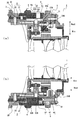
- FIG. 1 is a cross-sectional view showing an example of the configuration of a lens barrel according to the present invention.
- FIGS. 2A and 2B are enlarged sectional views of the lens barrel shown in FIG.
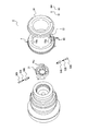
- FIG. 3 is a partially exploded perspective view showing an example of the configuration of the lens barrel according to the present invention.
- FIG. 4 is a partially exploded perspective view showing an example of the configuration of the lens barrel according to the present invention.
- FIG. 5 is a front view showing an example of the configuration of the diaphragm blades.
- 6A is a plan view showing the F value display portion (G arrow view in FIG. 1)
- FIG. 6B is a plan view showing the T value display portion (H arrow in FIG. 1). View).
- FIG. 1 is a cross-sectional view showing an example of the configuration of a lens barrel according to the present invention.
- FIGS. 2A and 2B are enlarged sectional views of the lens barrel shown in FIG.
- FIG. 3 is a partially exploded perspective
- FIG. 7 is a plan view showing an example of a conventional configuration of a lens barrel with an aperture adjustment function.
- FIG. 8A is a partial cross-sectional view showing another example of the conventional configuration of a lens barrel with an aperture adjustment function, and
- FIG. 8B is an enlarged cross-sectional view thereof.
- FIG. 9 is a sectional view showing another example of the configuration of the lens barrel according to the present invention.
- FIG. 10 is an exploded perspective view showing the configuration of the lens barrel shown in FIG.
- the lens barrel according to the present invention is illustrated by reference numerals 1,301 in FIGS. 1 to 4, 9, and 10.
- a diaphragm portion 2,302 capable of changing the size of the opening diameter
- a fixed cylinder portion 3,303 for accommodating the throttle portion 2,302
- a diaphragm ring 4,304 that is rotatably attached to the fixed cylinder part 3,303 and is configured to be able to adjust the opening diameter of the diaphragm part 2,302; It has.
- the diaphragm unit 2,302 is an iris diaphragm, and as illustrated in FIG. 5, a plurality of diaphragm blades 20 having cam shafts 20a, 20b and a plurality of the shafts 20a, 20b are inserted.
- An annular operation member (see reference numeral 21 in FIGS. 3 and 4 and reference numeral 321 in FIGS. 9 and 10) formed with a cam hole (see reference numeral 21a in FIGS. 3 and 4 and reference numeral 321a in FIG. 10); It is good to comprise by.
- the fixed cylindrical portion 3 and the fixed cylindrical portion 303 illustrated in the figure are formed by integrally connecting a plurality of cylindrical members 30, 31 or a plurality of cylindrical members 330, 331 with screws. There may be.
- the lens barrel 1,301 according to the present invention includes connecting portions 5,305 for connecting the diaphragm portions 2,302 and the diaphragm rings 4,304 so as to be able to contact and separate from each other.
- 305 is The circumferential direction of the throttle portion 2,302 so as to be biased toward the throttle ring 4,304 side (preferably from the throttle portion 2,302 toward the throttle ring 4,304 side) (FIG.
- 1st and 2nd projection part 50A, 50B arrange
- the first and second protrusions 50A and 50B (or the first and second protrusions 350A and 350B) are selectively fitted according to the rotational position of the diaphragm rings 4 and 304, and the diaphragm ring Fitting parts 51 and 351 formed on the side of the throttle ring 4 and 304 so that the four and 304 rotate integrally with the throttle parts 2 and 302;
- the fitting of the first and second protrusions 50A and 50B (or the first and second protrusions 350A and 350B) into the fitting parts 51 and 351 that is, the fitting parts 51 and 351
- the first protrusions 50A and 350A are fitted, the first protrusions 50A and 350A are fitted, and the first protrusions 50A and 350A are fitted in the fitting parts 51 and 351.
- FIGS. 1, 2 and 3 and 4 show the circumferential position of the fitting portion 51 in the diaphragm ring 4 (that is, the circumferential direction between the fitting portion 51 and a locked portion 62 described later). The relative positional relationship is different.
- the first and second protrusions 50A and 50B are configured to be urged in the lens barrel outer direction Rout.
- the present invention is not limited to this, and may be biased in another direction (for example, the optical axis direction x) as long as it is biased toward the diaphragm ring 4,304.
- the positions of the fitting portions 51 and 351 are also positions other than the inner peripheral surface of the aperture rings 4 and 304 (the first and second protrusions 50A and 50B or the first and second protrusions 350A and 350B are urged). May be changed as appropriate. For example, in FIG. 1 and FIG.
- the first projecting portion 50A and the second projecting portion 50B are disposed on the same, and the location where the spring member indicated by reference numeral 60 is disposed and the other location shifted in the circumferential direction from the location (for example, a location shifted by 180 °) ),
- the first and second spring members 53A and 53B (details will be described later) are arranged, and the projections 50A and 50B are urged in the optical axis direction (for example, the direction opposite to the x direction). You may do it.
- the fitting portion 51 is preferably formed at a place where a locked portion (details will be described later) indicated by reference numeral 62 is disposed.
- connection release part 52 352
- Actuator portions 520 and 3520 arranged at positions where the first and second protrusion portions 50A and 50B (or the first and second protrusion portions 350A and 350B) in the fitting portions 51 and 351 are urged;
- Push button portions 521 and 3521 connected to the actuator portions 520 and 3520 and arranged so as to protrude from the outer peripheral surfaces 4a and 304a of the aperture rings 4 and 304 in the lens barrel outer direction Rout;
- the actuator portions 520 and 3520 cause the first or second protrusion portions 50A and 50B (first or second protrusion portions 350A and 350A, 350B) is pushed out from the fitting portions 51 and 351 in the lens barrel inward direction Rin, and the fitting portion 51 of the first or second projecting portion 50A or 50B (first or second projecting portion 350A or 350B).
- a through hole is formed in the aperture rings 4 and 304 and the push button portions 521 and 3521 are arranged so as to be inserted through the through holes.
- a through hole is not formed.
- a notch (not shown) or a gap (that is, a gap between the fixed cylindrical portions 31 and 331) is provided in the aperture rings 4 and 304 so as to protrude in the lens barrel outward direction Rout.
- the push button portions 521 and 3521 may be arranged.
- the push button portions 521 and 3521 may be kept pressed while the diaphragm rings 4 and 304 are rotated, but the first or second protrusions 50A and 50B (first or second protrusions). 350A, 350B) and the fitting portions 51, 351 need not be continuously pressed when they are disengaged. According to the present invention, since the push button portions 521 and 3521 are arranged so as to protrude from the outer peripheral surfaces 4a and 304a of the diaphragm rings 4 and 304 in the lens barrel outer direction Rout, the diaphragm rings 4 and 304 are disposed. Can be pushed in while holding the hand, and the operation becomes simple.
- the first and second protrusions 50A and 50B are fitted into the fitting parts 51 and 351 and the connection release parts 52 and 352, respectively. May be placed in two places, but only in one place, In the state in which the first protrusions 50A and 350A are fitted in the fitting parts 51 and 351, the second protrusions 50B and 350B are not engaged with the aperture rings 4 and 304, The first protrusions 50A and 350A are not engaged with the aperture rings 4 and 304 when the second protrusions 50B and 350B are fitted in the fitting parts 51 and 351. It is good to do so. In such a case, the diaphragm ring 4,304 can be freely rotated only by operating the connection release portions 52, 352 provided at one place, and the connection release operation can be simplified. it can.
- the fitting portions 51 and 351 have a groove shape extending in the optical axis direction x of the lens barrel 1,301. It may be a recess not included in the concept of a groove. Further, the fitting portions 51 and 351 are formed as convex portions instead of grooves and concave portions, and concave portions and groove portions are formed at the tip portions of the projection portions 50A and 50B (or the projection portions 350A and 350B). You may make it a part and this projection part latch. Furthermore, in the example shown in FIGS. 1 and 9, the first and second protrusions 50A and 50B (or the first and second protrusions 350A and 350B) are separated by 180 ° along the circumferential direction C. However, the present invention is not limited to this and may be arranged at an appropriate position.
- the urging force of the first and second protrusions 50A and 50B (or the first and second protrusions 350A and 350B) in the lens barrel outward direction Rout is attached to the apertures 2 and 302 side.
- the first and second spring members 53A and 53B (or the first and second spring members 353A and 353B) may be used.
- 2 (a) b (b) and the members indicated by reference numerals 354A and 354B in FIG. 10 are connected to the first and second spring members 53A and 53B by the restricting portion 2 (more precisely, , A member for attaching to the operation member 21).
- 9 and 10 are connected to the throttle portions 2 and 302 and the first spring member 53A.
- the coil spring is interposed between the first and second protrusions 50A and 50B (or the first and second protrusions 350A and 350B), but is not limited to this, and may have other shapes. May be.
- the lens barrel 1,301 includes click mechanisms 6,306 formed or arranged in the first opposing part P1 and the second opposing part P2.
- the first facing portion P1 and the second facing portion P2 illustrated in FIG. 2B are the end face portions of the diaphragm ring 4 and the fixed cylinder portion 3 (that is, the end face in the optical axis direction x and the end face of the end face).
- the present invention is not limited to this, and it is sufficient that the opposing portions P1 and P2 are opposed to each other.
- the peripheral surface portion 303 that is, the outer peripheral surface and its vicinity, the inner peripheral surface and its vicinity
- other portions may be used. For example, in FIG. 1 and FIG.
- a locking member 61 described below is disposed at a position where the first protrusion 50A or the second protrusion 50B is disposed, and the first spring member 53A or A click spring member 60 to be described below is disposed at a position where the second spring member 53B is disposed, and next to an inner peripheral surface of the aperture ring 4 (that is, a position where the fitting portion 51 is formed). You may make it arrange
- the locking members 61 and 361 are the surfaces to be locked. Sliding P2a, When the diaphragm rings 4 and 304 are rotated in a state where the second protrusions 50B and 350B are fitted in the fitting parts 51 and 351, the locking members 61 and 361 are set to the substantially flat surface P2b. Is configured to slide.
- the portion of the fixed cylindrical portion 3 (cylindrical member 31) that opposes the aperture ring 4 is defined as a first opposing portion P1 on the side of the fixed cylindrical portion 3 for the click.
- the spring member 60 is arranged, and the portion of the throttle ring 4 is used as the second opposing portion P2, and the locked portion 62 is formed in the portion of the throttle ring 4, but the opposite, that is, the portion of the throttle ring 4 is formed.
- the click spring member 60 may be disposed on the fixed cylinder portion 3 and the locked portion 62 may be formed on the fixed cylinder portion 3.
- the click spring member 360 is disposed on the side of the throttle ring 304 with the portion of the throttle ring 304 as the first opposing portion P ⁇ b> 1, and the cylindrical portion 333 that faces the throttle ring 304.
- the locked portion 362 is formed at the portion of the cylindrical portion 333 with the portion as the second opposing portion P2, but the reverse, that is, the click spring member 360 is disposed at the portion of the cylindrical portion 333, and The locked portion 362 may be formed in the aperture ring 304 portion.
- an index Q is displayed on the fixed cylindrical portion 3, 303 (annular members 32, 332) at a position close to the diaphragm ring 4, 304, and the diaphragm ring is displayed.
- 4,304 includes A plurality of F in a circumferential range that can face the index Q when the aperture ring 4, 304 is rotated in a state where the first protrusions 50 ⁇ / b> A, 350 ⁇ / b> A are fitted in the fitting portions 51, 351.
- the narrowed portions 2, 302 (and the positions of the fitting portions 51, 351 and the first and second protrusions 50A, 50B (or the first, second protrusions 350A, 350B)) are the index Q. It is preferable to form an opening having a size that realizes the F value 4A or the T value 4B opposite to the.
- the F value is a value obtained by dividing the focal length of the lens by the effective aperture, and corresponds to the brightness when the transmittance of the lens is assumed to be 100%.
- the T value is an index indicating substantial brightness taking into account the transmittance of the optical system (that is, actual brightness reaching the sensor), and the relationship with the F value is expressed by the following equation. .
- the aperture is adjusted using the F value for still image shooting, but the aperture adjustment is performed using the T value for moving image shooting.
- the aperture adjustment is performed using the T value for moving image shooting.
- the camera according to the present invention described in claim 5 includes the lens barrel 1,301 having the above-described configuration.
- the lens barrel 1,301 is preferably a replaceable type, but does not exclude a non-replaceable type (that is, a lens barrel as a component constituting the camera).
Landscapes
- Physics & Mathematics (AREA)
- General Physics & Mathematics (AREA)
- Optics & Photonics (AREA)
- Lens Barrels (AREA)
- Diaphragms For Cameras (AREA)
Abstract
Description
前記固定筒部(3,303)に対向する前記絞り環(4,304)の部分又は前記絞り環(4,304)に対向する前記固定筒部(3,303)の部分を“第1対向部位(図2(b) 及び図9の符号P1参照)”とし、該第1対向部位(P1)に対向する前記固定筒部(3,303)の部分又は前記絞り環(4,304)の部分を“第2対向部位(同図の符号P2参照)”とした場合に、
前記絞り部(2,302)から前記絞り環(4,304)の側に付勢されるように該絞り部(2,302)の周方向(図3及び図4の矢印C参照)に沿った2箇所に配置された第1及び第2突起部(50A,50B、又は350A,350B)と、
前記絞り環(4,304)の回動位置に応じて該第1及び第2突起部(50A,50B、又は350A,350B)が択一的に嵌まり込んで前記絞り環(4,304)が前記絞り部(2,302)と一体的に回動するように該絞り環(4,304)の側に形成された嵌合部(51,351)と、
該第1及び該第2突起部(50A,50B、又は350A,350B)の前記嵌合部(51,351)への嵌まり込みを解除して前記絞り環(4,304)が前記絞り部(2,302)と切り離された状態で回動するように構成された連結解除部(52,352)と、
前記絞り環(4,304)の回動にクリック感を付与するように前記第1対向部位(P1)及び前記第2対向部位(P2)に形成又は配置されたクリック機構(6,306)と、
を備え、
前記クリック機構(6,306)は、前記第1対向部位(P1)に取り付けられたクリック用バネ部材(60,360)と、該クリック用バネ部材(60,360)によって前記第2対向部位(P2)の側に付勢される係止部材(61,361)と、該係止部材(61,361)を係止するように前記第2対向部位(P2)の側に形成又は配置された被係止部(62,362)と、を有し、
前記第2対向部位(P2)は、周方向(C)に複数の前記被係止部(62,362)が形成されてなる被係止面(図3の符号P2a参照)と、該被係止部(62,362)を有しない略平坦面(図3の符号P2b参照)と、を有し、
前記第1突起部(50A,350A)が前記嵌合部(51,351)に嵌まり込んだ状態で前記絞り環(4,304)を回動した場合には前記係止部材(61,361)は前記被係止面(P2a)を摺動し、前記第2突起部(50B,350B)が前記嵌合部(51,351)に嵌まり込んだ状態で前記絞り環(4,304)を回動した場合には前記係止部材(61,361)は前記略平坦面(P2b)を摺動するように構成されたことを特徴とする。
前記第1及び第2突起部(50A,50B、又は350A,350B)を該鏡筒外方向(Rout)に付勢するように前記絞り部(2,302)の側に取り付けられた第1及び第2バネ部材(53A,53B、又は353A,353B)、
を備え、
前記嵌合部(51,351)は前記絞り環(4,304)の内周面に形成され、
前記連結解除部(52,352)は、前記嵌合部(51,351)における前記第1及び第2突起部(50A,50B、又は350A,350B)が付勢される位置に配置されたアクチュエータ部(520,3520)と、該アクチュエータ部(520,3520)に連結されると共に前記絞り環(4,304)の外周面から前記鏡筒外方向(Rout)に突出するように配置された押しボタン部(521,3521)と、からなり、
該押しボタン部(521,3521)を前記鏡筒内方向(Rin)に押すことによって前記アクチュエータ部(520,3520)が前記第1又は第2突起部(50A,50B、又は350A,350B)を前記嵌合部(51,351)から該鏡筒内方向(Rin)に押し出して該第1又は該第2突起部(50A,50B、又は350A,350B)の前記嵌合部(51,351)への嵌まり込みを解除するように構成されたことを特徴とする。
該絞り環(4,304)には、前記嵌合部(51,351)に前記第1突起部(50A,350A)が嵌め込まれた状態で該絞り環(4,304)が回動された場合において前記指標(Q)に対向し得る周方向範囲に複数のF値(4A)が表示されると共に、前記嵌合部(51,351)に前記第2突起部(50B,350B)が嵌め込まれた状態で該絞り環(4,304)が回動された場合において前記指標(Q)に対向し得る周方向範囲に複数のT値(4B)が表示され、
前記絞り部(2,302)は、前記指標(Q)に対向するF値(4A)又はT値(4B)を実現する大きさの開口を形成するように構成されたことを特徴とする。
・ 開口径の大きさを変更可能な絞り部2,302と、
・ 該絞り部2,302を収容する固定筒部3,303と、
・ 該固定筒部3,303に回動可能に取り付けられて前記絞り部2,302の開口径を調整可能に構成された絞り環4,304と、
を備えている。
・ 前記絞り環4,304の側に(好ましくは、前記絞り部2,302から前記絞り環4,304の側に)付勢されるように該絞り部2,302の周方向(図3、図4及び図10の矢印C参照)に沿った2箇所に配置された第1及び第2突起部50A,50B(又は第1及び第2突起部350A,350B)と、
・ 前記絞り環4,304の回動位置に応じて該第1及び第2突起部50A,50B(又は第1及び第2突起部350A,350B)が択一的に嵌まり込んで前記絞り環4,304が前記絞り部2,302と一体的に回動するように該絞り環4,304の側に形成された嵌合部51,351と、
・ 該第1及び該第2突起部50A,50B(又は第1及び第2突起部350A,350B)の前記嵌合部51,351への嵌まり込み(つまり、該嵌合部51,351に嵌まり込んでいるのが第1突起部50A,350Aである場合にはその第1突起部50A,350Aの嵌まり込みであり、該嵌合部51,351に嵌まり込んでいるのが第2突起部50B,350Bである場合にはその第2突起部50B,350Bの嵌まり込み)を解除して前記絞り環4,304が前記絞り部2,302と切り離された状態で回動するように構成された連結解除部52,352と、
により構成されている。本発明によれば、クリック機能の停止と絞り値の変更とを行うために回動させるものは前記絞り環4,304のみであり、その操作及び構成が簡便となる。
・ 前記嵌合部51,351における前記第1及び第2突起部50A,50B(又は第1及び第2突起部350A,350B)が付勢される位置に配置されたアクチュエータ部520,3520と、
・ 該アクチュエータ部520,3520に連結されると共に前記絞り環4,304の外周面4a,304aから前記鏡筒外方向Routに突出するように配置された押しボタン部521,3521と、
により構成し、該押しボタン部521,3521を前記鏡筒内方向Rinに押すことによって前記アクチュエータ部520,3520が前記第1又は第2突起部50A,50B(第1又は第2突起部350A,350B)を前記嵌合部51,351から該鏡筒内方向Rinに押し出して該第1又は該第2突起部50A,50B(第1又は第2突起部350A,350B)の前記嵌合部51,351への嵌まり込みを解除するように構成しておくと良い。この場合、前記絞り環4,304には貫通孔を形成しておき、前記押しボタン部521,3521は該貫通孔に挿通されるように配置すると良いが、そのような貫通孔を形成せずに、前記絞り環4,304に切欠部(不図示)や隙間(つまり、前記固定筒部31,331との間の隙間)を設けておいて前記鏡筒外方向Routに突出するように前記押しボタン部521,3521を配置しても良い。なお、この押しボタン部521,3521は、前記絞り環4,304を回動させる間押し続けるようにしても良いが、前記第1又は第2突起部50A,50B(第1又は第2突起部350A,350B)と前記嵌合部51,351との係合が外れた段階で押し続けなくても良い。本発明によれば、前記押しボタン部521,3521は前記絞り環4,304の外周面4a,304aから前記鏡筒外方向Routに突出するように配置されているため、該絞り環4,304を握ったままで押し込むことができ、その操作が簡便となる。
・ 前記第1突起部50A,350Aが前記嵌合部51,351に嵌まり込んだ状態では前記第2突起部50B,350Bは前記絞り環4,304には係合されず、
・ 前記第2突起部50B,350Bが前記嵌合部51,351に嵌まり込んだ状態では前記第1突起部50A,350Aは前記絞り環4,304には係合されない、
ようにすると良い。そのようにした場合には、1箇所に設けられた前記連結解除部52,352を操作するだけで前記絞り環4,304は自由回動状態となり、その連結解除の操作を簡便にすることができる。
・ 前記第1対向部位P1に取り付けられたクリック用バネ部材60,360と、
・ 該クリック用バネ部材60,360によって前記第2対向部位P2の側に付勢される係止部材61,361と、
・ 該係止部材61,361を係止するように前記第2対向部位P2の側に形成又は配置された被係止部62,362と、
を有しており、該第2対向部位P2は、図3に例示するように、
・ 周方向Cに複数の前記被係止部62が形成されてなる被係止面P2aと、
・ 該被係止部62を有しない略平坦面P2bと、
を有している。図9の第2対向部位P2も、同様に被係止面と略平坦面とを有している。その結果、
・ 前記第1突起部50A,350Aが前記嵌合部51,351に嵌まり込んだ状態で前記絞り環4,304を回動した場合には前記係止部材61,361は前記被係止面P2aを摺動し、
・ 前記第2突起部50B,350Bが前記嵌合部51,351に嵌まり込んだ状態で前記絞り環4,304を回動した場合には前記係止部材61,361は前記略平坦面P2bを摺動する
ように構成されている。なお、図2(b) に示す例では、前記絞り環4に対向する前記固定筒部3(筒状部材31)の部分を第1対向部位P1として該固定筒部3の側に前記クリック用バネ部材60を配置し、前記絞り環4の部分を第2対向部位P2として該絞り環4の部分に被係止部62を形成しているが、その逆、つまり、該絞り環4の部分に前記クリック用バネ部材60を配置し、該固定筒部3の部分に前記被係止部62を形成しても良い。また、図9に示す例では、前記絞り環304の部分を第1対向部位P1として該絞り環304の側に前記クリック用バネ部材360を配置し、前記絞り環304に対向する筒部333の部分を第2対向部位P2として該筒部333の部分に被係止部362を形成しているが、その逆、つまり、該筒部333の部分に前記クリック用バネ部材360を配置し、前記絞り環304の部分に前記被係止部362を形成しても良い。
・ 前記嵌合部51,351に前記第1突起部50A,350Aが嵌め込まれた状態で該絞り環4,304が回動された場合において前記指標Qに対向し得る周方向範囲に複数のF値4Aを表示すると共に、
・ 前記嵌合部51,351に前記第2突起部50B,350Bが嵌め込まれた状態で該絞り環4,304が回動された場合において前記指標Qに対向し得る周方向範囲に複数のT値(つまり、レンズの透過率を考慮した実効絞り値)4Bを表示する、
ようにしておくと良い。そして、前記絞り部2,302(及び、前記嵌合部51,351や前記第1,2突起部50A,50B(又は前記第1,2突起部350A,350B)の位置)は、前記指標Qに対向するF値4A又はT値4Bを実現する大きさの開口を形成するように構成しておくと良い。なお、F値とは、レンズの焦点距離を有効口径で割った値であり、レンズの透過率を100%と仮定した場合の明るさに対応するものである。また、T値とは、光学系の透過率を加味した実質的な明るさ(つまり、センサーに到達する実際の明るさ)を示す指標であり、F値との関係は下式によって表される。

2 絞り部
3 固定筒部
4 絞り環
4A F値
4B T値
6 クリック機構
50A 第1突起部
50B 第2突起部
51 嵌合部
52 連結解除部
53A 第1バネ部材
53B 第2バネ部材
60 クリック用バネ部材
61 係止部材
62 被係止部
301 レンズ鏡筒
302 絞り部
303 固定筒部
304 絞り環
306 クリック機構
350A 第1突起部
350B 第2突起部
351 嵌合部
352 連結解除部
353A 第1バネ部材
353B 第2バネ部材
360 クリック用バネ部材
361 係止部材
362 被係止部
520 アクチュエータ部
521 押しボタン部
3520 アクチュエータ部
3521 押しボタン部
C 周方向
P1 第1対向部位
P2 第2対向部位
P2a 被係止面
P2b 略平坦面
Q 指標
Rin 鏡筒内方向
Rout 鏡筒外方向
Claims (5)
- 開口径の大きさを変更可能な絞り部と、該絞り部を収容する固定筒部と、該固定筒部に回動可能に取り付けられて前記絞り部の開口径を調整可能に構成された絞り環と、を備えたレンズ鏡筒において、
前記固定筒部に対向する前記絞り環の部分又は前記絞り環に対向する前記固定筒部の部分を“第1対向部位”とし、該第1対向部位に対向する前記固定筒部の部分又は前記絞り環の部分を“第2対向部位”とした場合に、
前記絞り部から前記絞り環の側に付勢されるように該絞り部の周方向に沿った2箇所に配置された第1及び第2突起部と、
前記絞り環の回動位置に応じて該第1及び第2突起部が択一的に嵌まり込んで前記絞り環が前記絞り部と一体的に回動するように該絞り環の側に形成された嵌合部と、
該第1及び該第2突起部の前記嵌合部への嵌まり込みを解除して前記絞り環が前記絞り部と切り離された状態で回動するように構成された連結解除部と、
前記絞り環の回動にクリック感を付与するように前記第1対向部位及び前記第2対向部位に形成又は配置されたクリック機構と、
を備え、
前記クリック機構は、前記第1対向部位に取り付けられたクリック用バネ部材と、該クリック用バネ部材によって前記第2対向部位の側に付勢される係止部材と、該係止部材を係止するように前記第2対向部位の側に形成又は配置された被係止部と、を有し、
前記第2対向部位は、周方向に複数の前記被係止部が形成されてなる被係止面と、該被係止部を有しない略平坦面と、を有し、
前記第1突起部が前記嵌合部に嵌まり込んだ状態で前記絞り環を回動した場合には前記係止部材は前記被係止面を摺動し、前記第2突起部が前記嵌合部に嵌まり込んだ状態で前記絞り環を回動した場合には前記係止部材は前記略平坦面を摺動するように構成された、
ことを特徴とするレンズ鏡筒。 - 前記レンズ鏡筒の半径方向外方を“鏡筒外方向”とし、該レンズ鏡筒の半径方向内方を“鏡筒内方向”とした場合に、
前記第1及び第2突起部を該鏡筒外方向に付勢するように前記絞り部の側に取り付けられた第1及び第2バネ部材、
を備え、
前記嵌合部は前記絞り環の内周面に形成され、
前記連結解除部は、前記嵌合部における前記第1及び第2突起部が付勢される位置に配置されたアクチュエータ部と、該アクチュエータ部に連結されると共に前記絞り環の外周面から前記鏡筒外方向に突出するように配置された押しボタン部と、からなり、
該押しボタン部を前記鏡筒内方向に押すことによって前記アクチュエータ部が前記第1又は第2突起部を前記嵌合部から該鏡筒内方向に押し出して該第1又は該第2突起部の前記嵌合部への嵌まり込みを解除するように構成された、
ことを特徴とする請求項1に記載のレンズ鏡筒。 - 前記押しボタン部は、前記絞り環に形成された貫通孔に挿通されるように配置された、
ことを特徴とする請求項2に記載のレンズ鏡筒。 - 前記固定筒部には、前記絞り環に近接する位置に指標が表示され、
該絞り環には、前記嵌合部に前記第1突起部が嵌め込まれた状態で該絞り環が回動された場合において前記指標に対向し得る周方向範囲に複数のF値が表示されると共に、前記嵌合部に前記第2突起部が嵌め込まれた状態で該絞り環が回動された場合において前記指標に対向し得る周方向範囲に複数のT値が表示され、
前記絞り部は、前記指標に対向するF値又はT値を実現する大きさの開口を形成するように構成された、
ことを特徴とする請求項1乃至3のいずれか1項に記載のレンズ鏡筒。 - 請求項1乃至4のいずれか1項に記載のレンズ鏡筒、
を備えたカメラ。
Priority Applications (4)
| Application Number | Priority Date | Filing Date | Title |
|---|---|---|---|
| JP2016547431A JP6557666B2 (ja) | 2014-09-08 | 2015-09-07 | レンズ鏡筒及びカメラ |
| EP15839442.9A EP3193200B1 (en) | 2014-09-08 | 2015-09-07 | Lens barrel and camera |
| CN201580046529.XA CN106796336B (zh) | 2014-09-08 | 2015-09-07 | 透镜镜筒以及相机 |
| US15/504,419 US10310358B2 (en) | 2014-09-08 | 2015-09-07 | Lens barrel and camera |
Applications Claiming Priority (4)
| Application Number | Priority Date | Filing Date | Title |
|---|---|---|---|
| JP2014-182445 | 2014-09-08 | ||
| JP2014182445 | 2014-09-08 | ||
| JP2015-021467 | 2015-02-05 | ||
| JP2015021467 | 2015-02-05 |
Publications (1)
| Publication Number | Publication Date |
|---|---|
| WO2016039294A1 true WO2016039294A1 (ja) | 2016-03-17 |
Family
ID=55459042
Family Applications (1)
| Application Number | Title | Priority Date | Filing Date |
|---|---|---|---|
| PCT/JP2015/075334 Ceased WO2016039294A1 (ja) | 2014-09-08 | 2015-09-07 | レンズ鏡筒及びカメラ |
Country Status (5)
| Country | Link |
|---|---|
| US (1) | US10310358B2 (ja) |
| EP (1) | EP3193200B1 (ja) |
| JP (1) | JP6557666B2 (ja) |
| CN (1) | CN106796336B (ja) |
| WO (1) | WO2016039294A1 (ja) |
Cited By (3)
| Publication number | Priority date | Publication date | Assignee | Title |
|---|---|---|---|---|
| WO2019035262A1 (ja) * | 2017-08-14 | 2019-02-21 | 富士フイルム株式会社 | レンズユニット、およびカメラシステム |
| JP2020129046A (ja) * | 2019-02-08 | 2020-08-27 | 株式会社シグマ | レンズ鏡筒 |
| WO2024058175A1 (ja) * | 2022-09-12 | 2024-03-21 | 株式会社ニコン | レンズ鏡筒及び撮像装置 |
Families Citing this family (2)
| Publication number | Priority date | Publication date | Assignee | Title |
|---|---|---|---|---|
| CN109143530B (zh) * | 2017-06-16 | 2021-06-18 | 宁波舜宇光电信息有限公司 | 镜头及包含该镜头的摄像模组 |
| CN116381889A (zh) * | 2023-03-28 | 2023-07-04 | 武汉高明兰光电科技有限公司 | 一种彩色照相机镜头 |
Citations (2)
| Publication number | Priority date | Publication date | Assignee | Title |
|---|---|---|---|---|
| WO2013031407A1 (ja) * | 2011-08-31 | 2013-03-07 | 富士フイルム株式会社 | レンズ装置及びこのレンズ装置を有する撮像装置 |
| JP5166597B1 (ja) * | 2011-12-27 | 2013-03-21 | 株式会社コシナ | レンズの絞り装置 |
Family Cites Families (4)
| Publication number | Priority date | Publication date | Assignee | Title |
|---|---|---|---|---|
| US3997264A (en) * | 1973-05-14 | 1976-12-14 | Minolta Camera Kabushiki Kaisha | Enlarging lens barrel |
| US4349265A (en) * | 1979-12-17 | 1982-09-14 | Canon Kabushiki Kaisha | Support structure for the aperture signal transmitting means in a camera lens assembly |
| JP6088733B2 (ja) * | 2011-11-29 | 2017-03-01 | オリンパス株式会社 | 撮像装置 |
| JP2013137505A (ja) * | 2012-10-01 | 2013-07-11 | Cosina Co Ltd | レンズの絞り装置 |
-
2015
- 2015-09-07 WO PCT/JP2015/075334 patent/WO2016039294A1/ja not_active Ceased
- 2015-09-07 US US15/504,419 patent/US10310358B2/en active Active
- 2015-09-07 EP EP15839442.9A patent/EP3193200B1/en active Active
- 2015-09-07 CN CN201580046529.XA patent/CN106796336B/zh active Active
- 2015-09-07 JP JP2016547431A patent/JP6557666B2/ja active Active
Patent Citations (2)
| Publication number | Priority date | Publication date | Assignee | Title |
|---|---|---|---|---|
| WO2013031407A1 (ja) * | 2011-08-31 | 2013-03-07 | 富士フイルム株式会社 | レンズ装置及びこのレンズ装置を有する撮像装置 |
| JP5166597B1 (ja) * | 2011-12-27 | 2013-03-21 | 株式会社コシナ | レンズの絞り装置 |
Cited By (6)
| Publication number | Priority date | Publication date | Assignee | Title |
|---|---|---|---|---|
| WO2019035262A1 (ja) * | 2017-08-14 | 2019-02-21 | 富士フイルム株式会社 | レンズユニット、およびカメラシステム |
| JPWO2019035262A1 (ja) * | 2017-08-14 | 2020-09-03 | 富士フイルム株式会社 | レンズユニット、およびカメラシステム |
| US10942427B2 (en) | 2017-08-14 | 2021-03-09 | Fujifilm Corporation | Lens unit and camera system |
| JP2020129046A (ja) * | 2019-02-08 | 2020-08-27 | 株式会社シグマ | レンズ鏡筒 |
| JP7195601B2 (ja) | 2019-02-08 | 2022-12-26 | 株式会社シグマ | レンズ鏡筒 |
| WO2024058175A1 (ja) * | 2022-09-12 | 2024-03-21 | 株式会社ニコン | レンズ鏡筒及び撮像装置 |
Also Published As
| Publication number | Publication date |
|---|---|
| CN106796336B (zh) | 2019-05-03 |
| EP3193200B1 (en) | 2019-07-17 |
| US20180224712A1 (en) | 2018-08-09 |
| JP6557666B2 (ja) | 2019-08-07 |
| CN106796336A (zh) | 2017-05-31 |
| EP3193200A4 (en) | 2018-04-25 |
| US10310358B2 (en) | 2019-06-04 |
| EP3193200A1 (en) | 2017-07-19 |
| JPWO2016039294A1 (ja) | 2017-06-15 |
Similar Documents
| Publication | Publication Date | Title |
|---|---|---|
| JP6557666B2 (ja) | レンズ鏡筒及びカメラ | |
| US8414204B2 (en) | Lens adaptor | |
| JP6500252B2 (ja) | レンズ鏡筒 | |
| JP2018066813A (ja) | 撮像装置およびマウントアダプタ | |
| JP5495860B2 (ja) | 光学防振装置および光学機器 | |
| US9063388B1 (en) | Interchangeable camera lens | |
| CN110300925A (zh) | 相机用滤镜框架以及相机用滤镜单元 | |
| JP6314318B2 (ja) | レンズ鏡筒 | |
| WO2017115465A1 (ja) | レンズ鏡筒およびこれを備えたカメラ | |
| US20110188137A1 (en) | Lens barrel and photographing apparatus inlcuding the same | |
| US9304284B2 (en) | Lens apparatus and image pickup apparatus including the same | |
| JP2007272163A (ja) | レンズフード | |
| HK1236626A1 (en) | Lens barrel and camera | |
| JP2015032375A (ja) | 回転式ダイヤル及び電子機器 | |
| HK1236626B (zh) | 透镜镜筒以及相机 | |
| JP2009151165A (ja) | エアレンズおよびエアレンズシステム | |
| JP2018072547A (ja) | レンズアダプタ、及び撮像装置 | |
| WO2015045831A1 (ja) | ロック機構付ダイヤル | |
| JP2016090949A (ja) | 三脚座及びそれを有するレンズ装置 | |
| US20250020982A1 (en) | Camera and switch | |
| JP3794061B2 (ja) | ワンタッチマウント及びワンタッチマウント付コンバージョンレンズ装置 | |
| JP2024112006A (ja) | レンズ鏡筒 | |
| JP5651087B2 (ja) | レンズ装置 | |
| JP2015138092A (ja) | 光学機器 | |
| JP2020112597A (ja) | レンズ装置、および撮像装置 |
Legal Events
| Date | Code | Title | Description |
|---|---|---|---|
| 121 | Ep: the epo has been informed by wipo that ep was designated in this application |
Ref document number: 15839442 Country of ref document: EP Kind code of ref document: A1 |
|
| ENP | Entry into the national phase |
Ref document number: 2016547431 Country of ref document: JP Kind code of ref document: A |
|
| REEP | Request for entry into the european phase |
Ref document number: 2015839442 Country of ref document: EP |
|
| WWE | Wipo information: entry into national phase |
Ref document number: 2015839442 Country of ref document: EP |
|
| WWE | Wipo information: entry into national phase |
Ref document number: 15504419 Country of ref document: US |
|
| NENP | Non-entry into the national phase |
Ref country code: DE |