WO2016042614A1 - 部分放電信号処理装置 - Google Patents
部分放電信号処理装置 Download PDFInfo
- Publication number
- WO2016042614A1 WO2016042614A1 PCT/JP2014/074519 JP2014074519W WO2016042614A1 WO 2016042614 A1 WO2016042614 A1 WO 2016042614A1 JP 2014074519 W JP2014074519 W JP 2014074519W WO 2016042614 A1 WO2016042614 A1 WO 2016042614A1
- Authority
- WO
- WIPO (PCT)
- Prior art keywords
- partial discharge
- discharge signal
- signal processing
- unit
- signal
- Prior art date
- Legal status (The legal status is an assumption and is not a legal conclusion. Google has not performed a legal analysis and makes no representation as to the accuracy of the status listed.)
- Ceased
Links
Images




Classifications
-
- G—PHYSICS
- G01—MEASURING; TESTING
- G01R—MEASURING ELECTRIC VARIABLES; MEASURING MAGNETIC VARIABLES
- G01R31/00—Arrangements for testing electric properties; Arrangements for locating electric faults; Arrangements for electrical testing characterised by what is being tested not provided for elsewhere
- G01R31/12—Testing dielectric strength or breakdown voltage ; Testing or monitoring effectiveness or level of insulation, e.g. of a cable or of an apparatus, for example using partial discharge measurements; Electrostatic testing
- G01R31/1227—Testing dielectric strength or breakdown voltage ; Testing or monitoring effectiveness or level of insulation, e.g. of a cable or of an apparatus, for example using partial discharge measurements; Electrostatic testing of components, parts or materials
- G01R31/1263—Testing dielectric strength or breakdown voltage ; Testing or monitoring effectiveness or level of insulation, e.g. of a cable or of an apparatus, for example using partial discharge measurements; Electrostatic testing of components, parts or materials of solid or fluid materials, e.g. insulation films, bulk material; of semiconductors or LV electronic components or parts; of cable, line or wire insulation
- G01R31/1272—Testing dielectric strength or breakdown voltage ; Testing or monitoring effectiveness or level of insulation, e.g. of a cable or of an apparatus, for example using partial discharge measurements; Electrostatic testing of components, parts or materials of solid or fluid materials, e.g. insulation films, bulk material; of semiconductors or LV electronic components or parts; of cable, line or wire insulation of cable, line or wire insulation, e.g. using partial discharge measurements
-
- G—PHYSICS
- G01—MEASURING; TESTING
- G01R—MEASURING ELECTRIC VARIABLES; MEASURING MAGNETIC VARIABLES
- G01R31/00—Arrangements for testing electric properties; Arrangements for locating electric faults; Arrangements for electrical testing characterised by what is being tested not provided for elsewhere
- G01R31/12—Testing dielectric strength or breakdown voltage ; Testing or monitoring effectiveness or level of insulation, e.g. of a cable or of an apparatus, for example using partial discharge measurements; Electrostatic testing
-
- G—PHYSICS
- G01—MEASURING; TESTING
- G01R—MEASURING ELECTRIC VARIABLES; MEASURING MAGNETIC VARIABLES
- G01R31/00—Arrangements for testing electric properties; Arrangements for locating electric faults; Arrangements for electrical testing characterised by what is being tested not provided for elsewhere
- G01R31/12—Testing dielectric strength or breakdown voltage ; Testing or monitoring effectiveness or level of insulation, e.g. of a cable or of an apparatus, for example using partial discharge measurements; Electrostatic testing
- G01R31/14—Circuits therefor, e.g. for generating test voltages, sensing circuits
Definitions
- the present invention relates to a partial discharge signal processing device that performs signal processing on a partial discharge signal inside an electric device.
- Partial discharge measurement performed to grasp the degree of insulation deterioration of high-voltage electrical equipment is roughly divided into offline measurement performed during shutdown and online measurement performed during operation, taking a turbine generator as an example.
- offline measurement a voltage near the rated voltage is applied to each phase of the armature using a high-voltage power supply while the turbine generator is stopped, and the partial discharge generated at that time is measured.
- online measurement since the rated voltage is generated in the armature during operation of the turbine generator, the partial discharge generated at that time is continuously measured over a long period of time.
- a partial discharge signal having a wide frequency component ranging from several kHz to several GHz is generated as a pulsed signal propagating in the conductor of the winding or an electromagnetic wave propagating through the space. And measure using an appropriate sensor.
- electromagnetic waves generated with partial discharge include signals ranging from several kHz to several GHz, and methods for measuring electromagnetic waves in the UHF band of 300 MHz to 3 GHz are being studied.
- the signal on the low frequency side (several kHz to several tens of MHz) has a relatively small signal attenuation during propagation, but is easily affected by noise, and the signal on the high frequency side (several hundred MHz to several GHz). ) Has a characteristic that the signal attenuation is relatively large but it is hardly affected by noise. For this reason, in off-line measurement with a relatively low noise level, a signal on the low frequency side is detected so that even partial discharges generated in the distance can be detected.
- on-line measurement with a relatively high noise level detects signals on the high frequency side that are not easily affected by noise, and the fact that the signal attenuation is large can be achieved by installing a sensor close to the partial discharge source, It is common to apply a high sensor.
- a waveguide antenna that receives electromagnetic waves is attached, and the waveguide antenna includes a waveguide section and a coaxial cable connector installed in the waveguide section.
- the waveguide portion is provided with a metal short-circuit plate at one end, and an opening is formed at the other end to cover a part of the outer peripheral surface of the insulating spacer. Accordingly, it is disclosed that even when a partial discharge detector is not previously installed inside the gas insulation device, it is possible to detect the partial discharge by detecting electromagnetic waves leaking from the gas insulation device. Has been.
- a coaxial cable capable of transmission is used as a transmission line.
- this coaxial cable has a greater signal attenuation as the frequency of the transmitted signal becomes higher.
- a coaxial cable with a smaller signal attenuation per unit length or a length of Although it is necessary to reduce the signal attenuation by using a short coaxial cable, in general, since the high-voltage electrical equipment is large, the distance between the receiving unit and the signal processing unit tends to be long. Therefore, it is necessary to use a long coaxial cable, and there is a problem that a partial discharge signal reaching the signal processing unit becomes extremely small.
- an amplifier that corrects the signal attenuation can be installed between the receiver and the signal processor.
- the frequency of the signal generated by the partial discharge has a certain bandwidth.
- the present invention has been made to solve the above-described problems, and even when a transmission line is used between the partial discharge signal receiving unit and the partial discharge signal processing unit, the signal is accurately received. It is an object of the present invention to provide a partial discharge signal processing apparatus capable of reproducing the intensity of the.
- a partial discharge signal processing device detects a partial discharge signal receiving unit that receives an electromagnetic wave generated by partial discharge in an electrical device as a partial discharge signal
- a partial discharge signal processing unit that performs signal processing, a transmission line that connects the partial discharge signal reception unit and the partial discharge signal processing unit and transmits the partial discharge signal
- the partial discharge signal processing unit includes a reference frequency Is set to 1 GHz or more, a frequency limiting unit that limits the frequency of the partial discharge signal with a frequency bandwidth of ⁇ 1% centered on the reference frequency, and the value of the partial discharge signal in the bandwidth is the transmission line
- An attenuation amount correction unit that corrects the signal based on the signal attenuation amount, and a signal output unit that outputs the corrected partial discharge signal to an external device.
- the partial discharge signal is received by receiving the electromagnetic wave generated by the partial discharge and limiting the partial discharge signal transmitted through the transmission line to a predetermined frequency and bandwidth.
- FIG. It is a figure which shows schematic structure of the partial discharge signal processing apparatus which concerns on Embodiment 1.
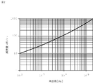
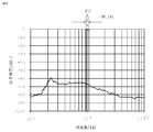
- FIG. It is a figure which shows an example of the signal attenuation characteristic of a coaxial cable. It is a figure which shows an example of the frequency characteristic of the electromagnetic waves by partial discharge. It is a figure which shows the reference frequency and bandwidth which are used for the partial discharge signal processing of the partial discharge signal processing apparatus which concerns on Embodiment 1.
- FIG. It is a figure which shows schematic structure of the partial discharge signal processing apparatus which concerns on Embodiment 2.
- FIG. It is a figure which shows an example of the frequency characteristic of the signal amplifier in the partial discharge signal processing apparatus which concerns on Embodiment 2.
- FIG. 1 It is a figure which shows schematic structure of the partial discharge signal processing apparatus which concerns on Embodiment 3.
- FIG. It is a figure which shows schematic structure of the partial discharge signal processing apparatus which concerns on Embodiment 4.
- FIG. It is a figure which shows schematic structure of the partial discharge signal processing apparatus which concerns on Embodiment 5.
- FIG. It is a figure which shows the other schematic structure of the partial discharge signal processing apparatus which concerns on Embodiment 5.
- FIG. 1 is a diagram showing a schematic configuration of a partial discharge signal processing device according to Embodiment 1
- FIG. 2 is a diagram showing an example of signal attenuation characteristics of a coaxial cable
- FIG. 3 is an electromagnetic wave caused by partial discharge.
- FIG. 4 is a diagram illustrating a reference frequency and a bandwidth used for partial discharge signal processing.
- a partial discharge signal processing apparatus includes a partial discharge signal receiving unit 1 installed inside or outside a high voltage electrical device, a partial discharge signal processing unit 2 installed outside the high voltage electrical device, and a partial discharge. It is comprised from three parts, the coaxial cable 3 as a transmission line which connects the signal receiving part 1 and the partial discharge signal processing part 2.
- the partial discharge signal receiving unit 1 includes an electromagnetic wave receiving unit 1a that detects an electromagnetic wave generated by the partial discharge.
- the partial discharge signal processing unit 2 includes a detection unit 2a that detects a partial discharge signal transmitted through the coaxial cable 3, and a band that limits the frequency band of the partial discharge signal detected by the detection unit 2a with a reference frequency as a center.
- the partial discharge receiving unit is installed inside or outside the high-voltage electrical device.
- the reception of the partial discharge is accompanied by the partial discharge.
- the partial discharge signal receiving unit 1 is assumed to be received within the high-voltage electrical apparatus.
- the partial discharge signal processing unit 2 is installed outside the high-voltage electrical device, and is connected to the partial discharge signal receiving unit 1 via a coaxial cable 3 of a transmission line.
- the partial discharge signal processing unit 2 performs signal processing of a high-frequency partial discharge signal transmitted through the coaxial cable 3, and the partial discharge signal is attenuated when passing through the coaxial cable 3.
- the amount of attenuation of this signal increases as the length of the coaxial cable 3 increases and as the frequency increases, as shown in the signal attenuation characteristics of the coaxial cable in FIG.
- the frequency characteristics of the electromagnetic waves due to partial discharge include, for example, a wide range of frequency components as shown in FIG. 3, so that when the detected electromagnetic waves are transmitted as a partial discharge signal through a coaxial cable, the attenuation is reduced in a low frequency region. However, the amount of attenuation increases in a high frequency region. In addition, in a large high-voltage electric device, the length of the coaxial cable 3 is increased, so that the amount of attenuation is further increased. For these reasons, the partial discharge signal received by the partial discharge signal processing unit 2 has intensity and frequency characteristics different from the signal received by the partial discharge signal receiving unit 1.
- the reference frequency f0 for performing the signal processing of the partial discharge signal in the partial discharge signal processing unit 2 is set to 1 GHz or more which is not easily affected by noise, and the signal of the coaxial cable 3 is centered on the reference frequency f0.
- the bandwidth ⁇ W is set so that the variation of the attenuation amount is within 0.1 dB so that the attenuation amount can be regarded as uniform.
- the signal attenuation by the coaxial cable 3 in the case of the bandwidth lower limit of 0.99 GHz is 565 dB.
- the signal attenuation is 575 dB / km, and the difference is 10 dB / km. Therefore, when the coaxial cable 3 having a length of 10 m is used, the signal attenuation amount at the bandwidth lower limit of 0.99 GHz is 5.65 dB, and the signal attenuation amount at the bandwidth upper limit of 1.01 GHz is 5.75 dB.
- the difference is 0.1 dB, and the signal attenuation can be regarded as uniform, that is, the bandwidth ⁇ W is ⁇ 0.01 GHz (reference frequency f0 of the reference frequency f0 with respect to 1.00 GHz of the reference frequency f0). ⁇ 1%), the difference in attenuation is 0.1 dB, and the partial discharge signal can be easily corrected.
- the reference frequency f0 is 1.00 GHz and the bandwidth ⁇ W is set to ⁇ 50% of 1.00 GHz
- the signal attenuation for .50 GHz is 340 dB / km
- the signal attenuation for the bandwidth upper limit of 1.50 GHz is 780 dB / km
- the difference is 440 dB / km.
- the signal attenuation at the bandwidth lower limit of 0.50 GHz is 3.40 dB
- the signal attenuation at the bandwidth upper limit of 1.50 GHz is 7.80 dB
- the difference is 4.40 dB.
- the signal attenuation can no longer be considered constant. If the length of the cable is further increased, the difference between the lower limit and the upper limit of the bandwidth is further increased, so that it is difficult to correct the partial discharge signal by the partial discharge signal processing unit 2 according to the length of the cable. Become.
- Narrowing the partial discharge signal bandwidth in the partial discharge signal processing is limited to the frequency band in which the signal handled in the partial discharge measurement is set, but there is an electromagnetic wave due to the partial discharge in this frequency band. Therefore, partial discharge measurement is possible, and as can be seen from the difference between online measurement and offline measurement, selecting the frequency band to be detected according to the purpose is a technique specific to partial discharge measurement. Thus, even if the frequency band for performing signal processing is narrowed, the essence of partial discharge measurement is not impaired.
- the attenuation amount is grasped in advance, and the bandwidth is set so that the signal attenuation amount can be regarded as uniform. Then, a correction coefficient for correcting the attenuation amount of the partial discharge signal in the attenuation amount correction unit 2c is determined.
- the attenuation used for correcting the partial discharge signal the attenuation at the reference frequency f0 may be used, or the average value of the attenuation at the frequency within the bandwidth ⁇ W may be used.
- the frequency region used for the partial discharge measurement can be selected anywhere as long as it includes the frequency of the electromagnetic wave caused by the partial discharge.
- the partial discharge signal has a uniform signal attenuation in the coaxial cable 3. It is necessary to set the bandwidth ⁇ W to such an extent that it can be regarded.
- the signal intensity of the partial discharge signal in the partial discharge signal processing unit 2 is partially corrected by determining the frequency band of the partial discharge signal for signal processing and correcting the signal attenuation amount by the coaxial cable 3 as a certain value. It is possible to correct the signal intensity at the discharge signal receiving unit 1 and to improve the accuracy of the partial discharge measurement by outputting to the external measuring device.
- the attenuation amount of the partial discharge signal is reduced by reducing the signal attenuation amount of the coaxial cable 3 by changing the cross-sectional dimension of the coaxial cable or changing the material, and shortening the wiring route of the coaxial cable 3, Furthermore, it is possible to measure a partial discharge signal with high accuracy. This effect becomes more prominent when a high frequency partial discharge signal with a large signal attenuation is handled.
- the electromagnetic wave generated by the partial discharge inside the high-voltage electric device is received, and the received electromagnetic wave is transmitted as a high-frequency partial discharge signal on the transmission line.
- the partial discharge signal is processed at a predetermined reference frequency and bandwidth so that the partial discharge signal can be accurately corrected without being affected by the frequency characteristics of the transmission line.
- the partial discharge signal can be accurately measured by outputting to an external measuring device.
- FIG. FIG. 5 is a diagram illustrating a schematic configuration of the partial discharge signal processing device according to the second embodiment
- FIG. 6 is a diagram illustrating an example of frequency characteristics of the signal amplifier.
- the attenuation correction unit has an amplification factor that matches the attenuation in the coaxial cable.
- This is a signal amplifying unit that amplifies the partial discharge signal. Since other components are the same as those in the first embodiment, the description thereof is omitted.
- a signal amplification unit 2e that amplifies the partial discharge signal with an amplification factor that matches the attenuation amount in the coaxial cable 3 as a function of the attenuation amount correction unit;
- the signal amplification unit In 2e the partial discharge signal is amplified in accordance with the attenuation.
- the amplification factor of the signal amplification unit 2e is determined in consideration of the length of the coaxial cable 3 and the attenuation characteristic in the set bandwidth ⁇ W.
- the signal amplification factor of the signal amplifier so as to correct the signal attenuation by the coaxial cable for each frequency.
- 6 has a frequency characteristic as shown in FIG. 6, the signal amplifier becomes complicated and expensive to correct the attenuation for each frequency. Further, the correction considering the length of the coaxial cable is further complicated.
- the frequency at which signal processing is performed is set to a bandwidth that allows the signal attenuation of the coaxial cable to be regarded as uniform, so there is no need to adjust the amplification factor for each frequency.
- the amplifier can be manufactured with a simple structure and at a low cost.
- the partial discharge signal attenuated by the transmission line by the signal amplifier is amplified only in the set bandwidth, so that it is the same as in the first embodiment.
- FIG. 7 is a diagram illustrating a schematic configuration of the partial discharge signal processing device according to the third embodiment.
- a plurality of partial discharge signal receiving units and partial discharge signal processing units that receive electromagnetic waves generated by partial discharges are prepared and provided at a plurality of locations in a high-voltage electric device. Since other components are the same as those in the first embodiment, the description thereof is omitted.
- a plurality of partial discharge signal receivers 1 and 10 (shown in FIG. 7 is a case where there are two partial discharge signal receivers) are attached to different locations of the high-voltage electrical equipment, Simultaneously received electromagnetic waves are processed as high-frequency partial discharge signals through the coaxial cables 3 and 30 by the transmission units 1b and 10b, and the partial discharge signal processing units 2 and 20 process the partial discharge signals. Since the operations in the partial discharge signal processing units 2 and 20 are the same as those in the first embodiment, the description thereof is omitted.
- each partial discharge signal can be accurately obtained. Can be processed. As a result, partial discharges can be captured simultaneously at multiple locations on high-voltage electrical equipment, and by comparing these, accurate partial discharge signal information can be obtained, making it easy to monitor abnormalities and identify abnormal locations. become.
- the partial discharge signal processing device by preparing a plurality of partial discharge signal receiving units and simultaneously processing the partial discharge signals, the same effect as in the first embodiment is obtained.
- partial discharges can be captured simultaneously at multiple locations on high-voltage electrical equipment. By comparing these, accurate partial discharge signal information can be obtained, making it easy to monitor abnormalities and identify abnormal locations. There is an effect of becoming.
- FIG. FIG. 8 is a diagram illustrating a schematic configuration of the partial discharge signal processing device according to the fourth embodiment.
- the fourth embodiment includes a storage unit that stores the attenuation characteristics of the coaxial cable in the partial discharge signal processing unit. Since other configurations are the same as those of the first embodiment, description thereof is omitted.
- the partial discharge signal processing unit 2 is provided with a storage unit 2f, and the storage unit 2f stores the attenuation characteristics of the coaxial cable 3 shown in FIG. 2, and the stored data is referred to. Then, the attenuation correction unit 2c corrects the attenuated partial discharge signal. If the length of the coaxial cable 3 is known, the amount of attenuation by the coaxial cable 3 can be estimated by inputting the length into the partial discharge signal processing unit 2, and the attenuated partial discharge signal is received by the partial discharge signal. The intensity of the partial discharge signal received by the unit 1 can be easily restored. Since other operations in the partial discharge signal processing unit 2 are the same as those in the first embodiment, description thereof will be omitted.
- the storage unit is provided in the partial discharge signal processing unit, and the attenuation characteristic of the transmission line is stored, so that the same as in the first embodiment.
- the attenuation can be easily estimated even if the length of the transmission line changes, and the intensity of the partial discharge signal can be accurately corrected.
- FIG. 9 is a diagram illustrating a schematic configuration of the partial discharge signal processing device according to the fifth embodiment.
- the difference from the partial discharge signal processing device according to the first embodiment is that, in the fifth embodiment, the partial discharge signal processing unit is provided with an attenuation amount measurement unit that measures the attenuation characteristics of the coaxial cable. Since other configurations are the same as those of the first embodiment, description thereof is omitted.
- the partial discharge signal processing unit 2 is provided with an attenuation measurement unit 2 g, and in order to measure the attenuation of the coaxial cable 3, a reference from the transmission unit 1 b installed in the partial discharge signal reception unit 1.
- An attenuation measurement signal having a predetermined intensity at the frequency f0 is sent to the coaxial cable 3, and the attenuation measurement signal 2g of the partial discharge signal processing unit 2 receives the attenuation measurement signal and measures the attenuation.
- the attenuation correction unit 2c corrects the attenuated partial discharge signal.
- the detection unit 2a may have the function of the attenuation measurement unit 2g.
- an attenuation measurement signal having a predetermined intensity at the reference frequency f0 is sent from the attenuation measurement unit 2g to the coaxial cable 3 to perform partial discharge. It is also possible to measure the amount of attenuation by receiving the attenuation measurement signal that is turned back by the transmission unit 1b of the signal reception unit 1 and passed through the coaxial cable 3 by the attenuation measurement unit 2g.
- the attenuation measurement unit is provided in the partial discharge signal processing unit, and the attenuation characteristic of the transmission line is measured, so that the same as in the first embodiment.
- the attenuation can be accurately determined even if the length of the transmission line changes, and the intensity of the partial discharge signal can be accurately corrected.
- the present invention can be freely combined with each other, or can be appropriately modified or omitted.
Landscapes
- Physics & Mathematics (AREA)
- General Physics & Mathematics (AREA)
- Testing Relating To Insulation (AREA)
Abstract
Description
図1は、実施の形態1に係る部分放電信号処理装置の概略構成を示す図であり、図2は、同軸ケーブルの信号減衰特性の一例を示す図であり、図3は、部分放電による電磁波の周波数特性の一例を示す図であり、図4は、部分放電信号処理に使用する基準周波数および帯域幅を示す図である。
一般的には、部分放電受信部は、高電圧電気機器の内部または外部に設置されるが、例えば、図1に示すように、本実施の形態では、部分放電の受信は、部分放電に伴って発生する電磁波を受信するものとし、部分放電信号受信部1は、高電圧電気機器の内部に設置される場合について説明する。また、部分放電信号処理部2は、高電圧電気機器の外部に設置され、部分放電信号受信部1とは伝送線の同軸ケーブル3を介して接続されている。
図5は、実施の形態2に係る部分放電信号処理装置の概略構成を示す図であり、図6は、信号増幅器の周波数特性の一例を示す図である。図1に示す実施の形態1に係る部分放電信号処理装置との違いは、実施の形態2に係る部分放電信号処理装置では、減衰量補正部を同軸ケーブルでの減衰量に合わせた増幅率で部分放電信号を増幅する信号増幅部とした点である。他の構成要素については、実施の形態1と同じであるので説明を省略する。
実施の形態2では、同軸ケーブル3での減衰量を補正するために、減衰量補正部の機能として同軸ケーブル3での減衰量に合わせた増幅率で部分放電信号を増幅する信号増幅部2eとしたものであり、基準周波数f0を中心とする帯域幅ΔWにおける部分放電信号受信部1と部分放電信号処理部2との間で減衰した部分放電信号の強度の補正を行うために、信号増幅部2eにおいて減衰量に合わせた部分放電信号の増幅を行う。ここでは、信号増幅部2eの増幅率は、同軸ケーブル3の長さ、設定された帯域幅ΔWにおける減衰特性を考慮して決定する。
図7は、実施の形態3に係る部分放電信号処理装置の概略構成を示す図である。実施の形態3に係る部分放電信号処理装置では、部分放電により発生した電磁波を受信する部分放電信号受信部及び部分放電信号処理部を複数用意し、高電圧電気機器の複数個所に設けたものであり、他の構成要素については、実施の形態1と同じであるので説明を省略する。
複数の部分放電信号受信部1,10(図7では、部分放電信号受信部が2つである場合を示す。)が、高電圧電気機器の異なる箇所に取付けられ、電磁波受信部1a,10aで同時に受信された電磁波を高周波の部分放電信号として送信部1b、10bにより同軸ケーブル3,30を通して、部分放電信号処理部2,20により部分放電信号の処理を行うものである。部分放電信号処理部2,20での動作については、実施の形態1と同様であるので、説明を省略する。部分放電信号受信部1,10と部分放電信号処理部2,20とを接続する同軸ケーブル3,30の長さによる減衰量の違いや周波数特性を補正することで、それぞれの部分放電信号を正確に処理することができる。これにより、高電圧電気機器の複数箇所で、同時に部分放電を捉えることができ、これらを比較することにより、正確な部分放電信号の情報を得ることができ、異常監視、異常個所の把握が容易になる。
図8は、実施の形態4に係る部分放電信号処理装置の概略構成を示す図である。実施の形態1に係る部分放電信号処理装置との相違点は、実施の形態4では、部分放電信号処理部に同軸ケーブルの減衰特性を記憶した記憶部を備えていることである。その他の構成については、実施の形態1と同じであるので説明を省略する。
図8に示すように、部分放電信号処理部2に、記憶部2fが設けられ、記憶部2fには図2で示す同軸ケーブル3の減衰特性が記憶されており、この記憶されたデータを参照して、減衰量補正部2cにて、減衰された部分放電信号を補正する。同軸ケーブル3の長さが分かれば、その長さを部分放電信号処理部2に入力することによって、同軸ケーブル3による減衰量を推定することができ、減衰された部分放電信号を部分放電信号受信部1で受信した部分放電信号の強度に容易に戻すことができる。部分放電信号処理部2での他の動作については、実施の形態1と同様であるので、説明を省略する。
図9は、実施の形態5に係る部分放電信号処理装置の概略構成を示す図である。実施の形態1に係る部分放電信号処理装置との相違点は、実施の形態5では、部分放電信号処理部に同軸ケーブルの減衰特性を測定する減衰量測定部を備えていることである。その他の構成については、実施の形態1と同じであるので説明を省略する。
図9に示すように、部分放電信号処理部2に、減衰量測定部2gが設けられ、同軸ケーブル3の減衰量を測定するため、部分放電信号受信部1に設置された送信部1bから基準周波数f0で所定の強度を持つ減衰量測定信号を同軸ケーブル3に送り、部分放電信号処理部2の減衰量測定部2gで減衰量測定信号を受信して減衰量を測定する。この測定された減衰量に基づいて、減衰量補正部2cにて、減衰された部分放電信号を補正する。これにより、同軸ケーブル3の長さが変わっても実際の同軸ケーブル3による減衰量を決定することができ、部分放電伝送時に減衰された部分放電信号を部分放電信号受信部1から送信された部分放電信号の強度に容易に戻すことができる。部分放電信号処理部2での他の動作については、実施の形態1と同様であるので、説明を省略する。上記説明では、新たに減衰量測定部2gを設ける例について説明したが、検出部2aに減衰量測定部2gの機能を持たせてもよい。
1b、10b 送信部、2、20 部分放電信号処理部、
3、30 同軸ケーブル、2a、20a 検出部、
2b、20b 帯域制限部、2c、20c 減衰量補正部、
2d、20d 信号出力部、2e 信号増幅部、2f 記憶部、
2g 減衰量測定部。
Claims (4)
- 電気機器内の部分放電により発生した電磁波を部分放電信号として受信する部分放電信号受信部、
前記部分放電信号を検出し、信号処理する部分放電信号処理部、
前記部分放電信号受信部と前記部分放電信号処理部とを接続し、前記部分放電信号を伝送する伝送線、を備え、
前記部分放電信号処理部は、基準周波数が1GHz以上に設定され、前記基準周波数を中心とする±1%の周波数の帯域幅で前記部分放電信号の周波数を制限する周波数制限部、前記帯域幅における前記部分放電信号の値を前記伝送線の信号減衰量に基づいて補正する減衰量補正部、補正された前記部分放電信号を外部の機器に出力する信号出力部、により構成されていることを特徴とする部分放電信号処理装置。 - 前記部分放電信号処理部は、前記帯域幅における前記伝送線による信号減衰量に基づいて、前記部分放電信号の値を増幅する増幅部を備えたものであることを特徴とする請求項1に記載の部分放電信号処理装置。
- 前記部分放電信号処理部は、前記伝送線の信号減衰量の特性値を記憶させた記憶部を備え、前記特性値を用いて、前記部分放電信号の値を補正することを特徴とする請求項1に記載の部分放電信号処理装置。
- 前記部分放電信号処理部は、前記伝送線の信号減衰量を測定する減衰量測定部を備え、測定された前記信号減衰量に基づいて、前記部分放電信号の値を補正することを特徴とする請求項1に記載の部分放電信号処理装置。
Priority Applications (5)
| Application Number | Priority Date | Filing Date | Title |
|---|---|---|---|
| PCT/JP2014/074519 WO2016042614A1 (ja) | 2014-09-17 | 2014-09-17 | 部分放電信号処理装置 |
| CN201480081982.XA CN106716153B (zh) | 2014-09-17 | 2014-09-17 | 局部放电信号处理装置 |
| JP2015508901A JP5872106B1 (ja) | 2014-09-17 | 2014-09-17 | 部分放電信号処理装置 |
| US15/313,437 US10048310B2 (en) | 2014-09-17 | 2014-09-17 | Partial discharge signal processing device |
| EP14901997.8A EP3196662B1 (en) | 2014-09-17 | 2014-09-17 | Partial discharge signal processing device |
Applications Claiming Priority (1)
| Application Number | Priority Date | Filing Date | Title |
|---|---|---|---|
| PCT/JP2014/074519 WO2016042614A1 (ja) | 2014-09-17 | 2014-09-17 | 部分放電信号処理装置 |
Publications (1)
| Publication Number | Publication Date |
|---|---|
| WO2016042614A1 true WO2016042614A1 (ja) | 2016-03-24 |
Family
ID=55362173
Family Applications (1)
| Application Number | Title | Priority Date | Filing Date |
|---|---|---|---|
| PCT/JP2014/074519 Ceased WO2016042614A1 (ja) | 2014-09-17 | 2014-09-17 | 部分放電信号処理装置 |
Country Status (5)
| Country | Link |
|---|---|
| US (1) | US10048310B2 (ja) |
| EP (1) | EP3196662B1 (ja) |
| JP (1) | JP5872106B1 (ja) |
| CN (1) | CN106716153B (ja) |
| WO (1) | WO2016042614A1 (ja) |
Families Citing this family (6)
| Publication number | Priority date | Publication date | Assignee | Title |
|---|---|---|---|---|
| CN105548844B (zh) * | 2016-01-26 | 2019-02-15 | 北京市劳动保护科学研究所 | 一种局部放电检测系统和方法 |
| CN108562834B (zh) * | 2018-02-06 | 2021-02-26 | 武汉康电电气有限公司 | 一种高压电缆局部放电在线监测系统及修正幅值的方法 |
| EP3796011A1 (de) * | 2019-09-18 | 2021-03-24 | Siemens Aktiengesellschaft | Auswerten von teilentladungssignalen |
| EP3796012A1 (de) * | 2019-09-19 | 2021-03-24 | Siemens Aktiengesellschaft | Erfassen einer teilentladung |
| JP7116831B1 (ja) * | 2021-08-03 | 2022-08-10 | 株式会社オーバル | 信号処理装置 |
| CN113433424B (zh) * | 2021-08-06 | 2022-05-03 | 广东电网有限责任公司 | 一种基于局部放电的配网线路树木坠落检测方法及系统 |
Citations (4)
| Publication number | Priority date | Publication date | Assignee | Title |
|---|---|---|---|---|
| JPH0484778A (ja) * | 1990-07-26 | 1992-03-18 | Tokyo Electric Power Co Inc:The | 部分放電測定方法 |
| JPH11231015A (ja) * | 1998-02-17 | 1999-08-27 | Mitsubishi Electric Corp | 回転電機の異常検出装置 |
| JP2011095036A (ja) * | 2009-10-28 | 2011-05-12 | Mitsubishi Electric Corp | 部分放電計測装置 |
| JP2012145368A (ja) * | 2011-01-07 | 2012-08-02 | Toshiba Corp | 周波数測定装置 |
Family Cites Families (15)
| Publication number | Priority date | Publication date | Assignee | Title |
|---|---|---|---|---|
| JP3072958B2 (ja) * | 1995-04-11 | 2000-08-07 | 東京電力株式会社 | 部分放電測定方法 |
| DE69634129T2 (de) * | 1996-05-08 | 2005-12-08 | Mitsubishi Denki K.K. | Abnormalitätsdetektionsapparat und -verfahren |
| JP3685367B2 (ja) * | 1999-05-24 | 2005-08-17 | 三菱電機株式会社 | 回転電機の異常検出装置 |
| JP2001133503A (ja) * | 1999-11-01 | 2001-05-18 | Mitsubishi Heavy Ind Ltd | ノイズ検知方法及びこれを用いたメンテナンスシステム |
| JP2002071742A (ja) * | 2000-08-30 | 2002-03-12 | Mitsubishi Electric Corp | 部分放電検出装置および部分放電監視システム |
| JP4323418B2 (ja) | 2004-12-16 | 2009-09-02 | 株式会社日本Aeパワーシステムズ | ガス絶縁機器の異常状態診断方法およびシステム |
| JP2006250772A (ja) | 2005-03-11 | 2006-09-21 | Mitsubishi Electric Corp | 回転電機の部分放電計測装置および回転電機の絶縁診断方法 |
| JP5105841B2 (ja) * | 2006-12-04 | 2012-12-26 | 株式会社東芝 | 部分放電検出装置 |
| JP2008304357A (ja) * | 2007-06-08 | 2008-12-18 | Mitsubishi Electric Corp | 部分放電計測装置 |
| CN101387683A (zh) * | 2008-10-31 | 2009-03-18 | 东北电网有限公司长春超高压局 | 罐式断路器局部放电检测方法 |
| US9612271B2 (en) * | 2010-03-05 | 2017-04-04 | Ericsson Inc. | Evaluating noise and excess current on a power line |
| CN103516394B (zh) * | 2012-06-21 | 2016-08-24 | 中兴通讯股份有限公司 | 电缆的预补偿系数的获取方法和装置 |
| CN102914729B (zh) * | 2012-10-16 | 2015-08-05 | 西安交通大学 | 一种矿用电缆局部放电在线监测与定位脉冲发射装置 |
| CN103487728B (zh) | 2013-08-30 | 2016-06-08 | 广东电网公司电力科学研究院 | 测量gis局部放电的窄带电磁波信号耦合方法及检测系统 |
| CN103713241B (zh) * | 2013-12-13 | 2019-04-05 | 胡岳 | 基于m-bus的局部放电监测系统与方法 |
-
2014
- 2014-09-17 CN CN201480081982.XA patent/CN106716153B/zh active Active
- 2014-09-17 US US15/313,437 patent/US10048310B2/en active Active
- 2014-09-17 JP JP2015508901A patent/JP5872106B1/ja active Active
- 2014-09-17 WO PCT/JP2014/074519 patent/WO2016042614A1/ja not_active Ceased
- 2014-09-17 EP EP14901997.8A patent/EP3196662B1/en active Active
Patent Citations (4)
| Publication number | Priority date | Publication date | Assignee | Title |
|---|---|---|---|---|
| JPH0484778A (ja) * | 1990-07-26 | 1992-03-18 | Tokyo Electric Power Co Inc:The | 部分放電測定方法 |
| JPH11231015A (ja) * | 1998-02-17 | 1999-08-27 | Mitsubishi Electric Corp | 回転電機の異常検出装置 |
| JP2011095036A (ja) * | 2009-10-28 | 2011-05-12 | Mitsubishi Electric Corp | 部分放電計測装置 |
| JP2012145368A (ja) * | 2011-01-07 | 2012-08-02 | Toshiba Corp | 周波数測定装置 |
Also Published As
| Publication number | Publication date |
|---|---|
| EP3196662B1 (en) | 2020-03-11 |
| CN106716153B (zh) | 2019-07-09 |
| JP5872106B1 (ja) | 2016-03-01 |
| EP3196662A4 (en) | 2018-06-20 |
| EP3196662A1 (en) | 2017-07-26 |
| CN106716153A (zh) | 2017-05-24 |
| JPWO2016042614A1 (ja) | 2017-04-27 |
| US10048310B2 (en) | 2018-08-14 |
| US20170192048A1 (en) | 2017-07-06 |
Similar Documents
| Publication | Publication Date | Title |
|---|---|---|
| JP5872106B1 (ja) | 部分放電信号処理装置 | |
| US10291333B2 (en) | Measurement of voltage standing wave ratio of antenna system | |
| US7298128B2 (en) | Method of detecting RF powder delivered to a load and complex impedance of the load | |
| US10444273B2 (en) | Partial discharge measurement device | |
| JP4797175B2 (ja) | 部分放電電荷量測定方法および装置 | |
| NO342173B1 (en) | Method for measuring an impedance of an electric cable, a coupler arrangement and uses thereof | |
| CN106772170B (zh) | 一种uhf局部放电测量装置的校准方法 | |
| JP2008286715A (ja) | 部分放電測定装置 | |
| US20100010761A1 (en) | Method and device for monitoring a system | |
| JP6179969B2 (ja) | 無線カバレッジが可能であるか否か判定するシステム | |
| US9651974B2 (en) | Electrical power transmission line length measurement and average temperature estimation | |
| JP6059605B2 (ja) | 電磁妨害波耐力簡易試験装置 | |
| JP2011252780A (ja) | 磁界プローブを用いた電気機器の部分放電検出方法 | |
| US11041898B2 (en) | Method of locating a fault in a power transmission medium | |
| JP3895450B2 (ja) | 回転電機の異常検出装置 | |
| JP2013253804A (ja) | 校正装置 | |
| KR100508711B1 (ko) | 전력케이블에서의 부분방전 발생위치 추정시스템 | |
| JP5950396B2 (ja) | 部分放電発生位置の評定方法および評定システム | |
| JP2011252779A (ja) | 磁界プローブを用いた電気機器の部分放電検出方法 | |
| JPH04313074A (ja) | 回転電機の異常検出装置 | |
| CN113504417A (zh) | 一种用于电流法传导骚扰测量系统的准确性核查装置 | |
| CN106645875B (zh) | 宽频段稳态场下场线耦合电平的测试系统 | |
| KR101801082B1 (ko) | 노이즈 제거 기능을 구비한 액티브 부분방전 신호 검출 센서 장치 | |
| US20260019166A1 (en) | Radio transmitter test system | |
| JP2019179010A (ja) | パルス計測器およびパルス計測法 |
Legal Events
| Date | Code | Title | Description |
|---|---|---|---|
| ENP | Entry into the national phase |
Ref document number: 2015508901 Country of ref document: JP Kind code of ref document: A |
|
| 121 | Ep: the epo has been informed by wipo that ep was designated in this application |
Ref document number: 14901997 Country of ref document: EP Kind code of ref document: A1 |
|
| WWE | Wipo information: entry into national phase |
Ref document number: 15313437 Country of ref document: US |
|
| REEP | Request for entry into the european phase |
Ref document number: 2014901997 Country of ref document: EP |
|
| WWE | Wipo information: entry into national phase |
Ref document number: 2014901997 Country of ref document: EP |
|
| NENP | Non-entry into the national phase |
Ref country code: DE |