WO2016042783A1 - 車両用蓄電池装置 - Google Patents
車両用蓄電池装置 Download PDFInfo
- Publication number
- WO2016042783A1 WO2016042783A1 PCT/JP2015/050174 JP2015050174W WO2016042783A1 WO 2016042783 A1 WO2016042783 A1 WO 2016042783A1 JP 2015050174 W JP2015050174 W JP 2015050174W WO 2016042783 A1 WO2016042783 A1 WO 2016042783A1
- Authority
- WO
- WIPO (PCT)
- Prior art keywords
- vehicle
- storage battery
- housing
- flow path
- case
- Prior art date
- Legal status (The legal status is an assumption and is not a legal conclusion. Google has not performed a legal analysis and makes no representation as to the accuracy of the status listed.)
- Ceased
Links
Images


Classifications
-
- H—ELECTRICITY
- H01—ELECTRIC ELEMENTS
- H01M—PROCESSES OR MEANS, e.g. BATTERIES, FOR THE DIRECT CONVERSION OF CHEMICAL ENERGY INTO ELECTRICAL ENERGY
- H01M10/00—Secondary cells; Manufacture thereof
- H01M10/60—Heating or cooling; Temperature control
- H01M10/62—Heating or cooling; Temperature control specially adapted for specific applications
- H01M10/625—Vehicles
-
- B—PERFORMING OPERATIONS; TRANSPORTING
- B60—VEHICLES IN GENERAL
- B60L—PROPULSION OF ELECTRICALLY-PROPELLED VEHICLES; SUPPLYING ELECTRIC POWER FOR AUXILIARY EQUIPMENT OF ELECTRICALLY-PROPELLED VEHICLES; ELECTRODYNAMIC BRAKE SYSTEMS FOR VEHICLES IN GENERAL; MAGNETIC SUSPENSION OR LEVITATION FOR VEHICLES; MONITORING OPERATING VARIABLES OF ELECTRICALLY-PROPELLED VEHICLES; ELECTRIC SAFETY DEVICES FOR ELECTRICALLY-PROPELLED VEHICLES
- B60L3/00—Electric devices on electrically-propelled vehicles for safety purposes; Monitoring operating variables, e.g. speed, deceleration or energy consumption
- B60L3/0023—Detecting, eliminating, remedying or compensating for drive train abnormalities, e.g. failures within the drive train
- B60L3/0046—Detecting, eliminating, remedying or compensating for drive train abnormalities, e.g. failures within the drive train relating to electric energy storage systems, e.g. batteries or capacitors
-
- B—PERFORMING OPERATIONS; TRANSPORTING
- B60—VEHICLES IN GENERAL
- B60L—PROPULSION OF ELECTRICALLY-PROPELLED VEHICLES; SUPPLYING ELECTRIC POWER FOR AUXILIARY EQUIPMENT OF ELECTRICALLY-PROPELLED VEHICLES; ELECTRODYNAMIC BRAKE SYSTEMS FOR VEHICLES IN GENERAL; MAGNETIC SUSPENSION OR LEVITATION FOR VEHICLES; MONITORING OPERATING VARIABLES OF ELECTRICALLY-PROPELLED VEHICLES; ELECTRIC SAFETY DEVICES FOR ELECTRICALLY-PROPELLED VEHICLES
- B60L50/00—Electric propulsion with power supplied within the vehicle
- B60L50/50—Electric propulsion with power supplied within the vehicle using propulsion power supplied by batteries or fuel cells
- B60L50/60—Electric propulsion with power supplied within the vehicle using propulsion power supplied by batteries or fuel cells using power supplied by batteries
- B60L50/64—Constructional details of batteries specially adapted for electric vehicles
-
- B—PERFORMING OPERATIONS; TRANSPORTING
- B60—VEHICLES IN GENERAL
- B60L—PROPULSION OF ELECTRICALLY-PROPELLED VEHICLES; SUPPLYING ELECTRIC POWER FOR AUXILIARY EQUIPMENT OF ELECTRICALLY-PROPELLED VEHICLES; ELECTRODYNAMIC BRAKE SYSTEMS FOR VEHICLES IN GENERAL; MAGNETIC SUSPENSION OR LEVITATION FOR VEHICLES; MONITORING OPERATING VARIABLES OF ELECTRICALLY-PROPELLED VEHICLES; ELECTRIC SAFETY DEVICES FOR ELECTRICALLY-PROPELLED VEHICLES
- B60L50/00—Electric propulsion with power supplied within the vehicle
- B60L50/50—Electric propulsion with power supplied within the vehicle using propulsion power supplied by batteries or fuel cells
- B60L50/60—Electric propulsion with power supplied within the vehicle using propulsion power supplied by batteries or fuel cells using power supplied by batteries
- B60L50/66—Arrangements of batteries
-
- B—PERFORMING OPERATIONS; TRANSPORTING
- B60—VEHICLES IN GENERAL
- B60L—PROPULSION OF ELECTRICALLY-PROPELLED VEHICLES; SUPPLYING ELECTRIC POWER FOR AUXILIARY EQUIPMENT OF ELECTRICALLY-PROPELLED VEHICLES; ELECTRODYNAMIC BRAKE SYSTEMS FOR VEHICLES IN GENERAL; MAGNETIC SUSPENSION OR LEVITATION FOR VEHICLES; MONITORING OPERATING VARIABLES OF ELECTRICALLY-PROPELLED VEHICLES; ELECTRIC SAFETY DEVICES FOR ELECTRICALLY-PROPELLED VEHICLES
- B60L58/00—Methods or circuit arrangements for monitoring or controlling batteries or fuel cells, specially adapted for electric vehicles
- B60L58/10—Methods or circuit arrangements for monitoring or controlling batteries or fuel cells, specially adapted for electric vehicles for monitoring or controlling batteries
- B60L58/24—Methods or circuit arrangements for monitoring or controlling batteries or fuel cells, specially adapted for electric vehicles for monitoring or controlling batteries for controlling the temperature of batteries
- B60L58/26—Methods or circuit arrangements for monitoring or controlling batteries or fuel cells, specially adapted for electric vehicles for monitoring or controlling batteries for controlling the temperature of batteries by cooling
-
- H—ELECTRICITY
- H01—ELECTRIC ELEMENTS
- H01M—PROCESSES OR MEANS, e.g. BATTERIES, FOR THE DIRECT CONVERSION OF CHEMICAL ENERGY INTO ELECTRICAL ENERGY
- H01M10/00—Secondary cells; Manufacture thereof
- H01M10/60—Heating or cooling; Temperature control
- H01M10/61—Types of temperature control
- H01M10/613—Cooling or keeping cold
-
- H—ELECTRICITY
- H01—ELECTRIC ELEMENTS
- H01M—PROCESSES OR MEANS, e.g. BATTERIES, FOR THE DIRECT CONVERSION OF CHEMICAL ENERGY INTO ELECTRICAL ENERGY
- H01M10/00—Secondary cells; Manufacture thereof
- H01M10/60—Heating or cooling; Temperature control
- H01M10/65—Means for temperature control structurally associated with the cells
- H01M10/655—Solid structures for heat exchange or heat conduction
- H01M10/6551—Surfaces specially adapted for heat dissipation or radiation, e.g. fins or coatings
-
- H—ELECTRICITY
- H01—ELECTRIC ELEMENTS
- H01M—PROCESSES OR MEANS, e.g. BATTERIES, FOR THE DIRECT CONVERSION OF CHEMICAL ENERGY INTO ELECTRICAL ENERGY
- H01M10/00—Secondary cells; Manufacture thereof
- H01M10/60—Heating or cooling; Temperature control
- H01M10/65—Means for temperature control structurally associated with the cells
- H01M10/655—Solid structures for heat exchange or heat conduction
- H01M10/6552—Closed pipes transferring heat by thermal conductivity or phase transition, e.g. heat pipes
-
- H—ELECTRICITY
- H01—ELECTRIC ELEMENTS
- H01M—PROCESSES OR MEANS, e.g. BATTERIES, FOR THE DIRECT CONVERSION OF CHEMICAL ENERGY INTO ELECTRICAL ENERGY
- H01M10/00—Secondary cells; Manufacture thereof
- H01M10/60—Heating or cooling; Temperature control
- H01M10/65—Means for temperature control structurally associated with the cells
- H01M10/655—Solid structures for heat exchange or heat conduction
- H01M10/6556—Solid parts with flow channel passages or pipes for heat exchange
-
- H—ELECTRICITY
- H01—ELECTRIC ELEMENTS
- H01M—PROCESSES OR MEANS, e.g. BATTERIES, FOR THE DIRECT CONVERSION OF CHEMICAL ENERGY INTO ELECTRICAL ENERGY
- H01M10/00—Secondary cells; Manufacture thereof
- H01M10/60—Heating or cooling; Temperature control
- H01M10/65—Means for temperature control structurally associated with the cells
- H01M10/656—Means for temperature control structurally associated with the cells characterised by the type of heat-exchange fluid
- H01M10/6561—Gases
- H01M10/6563—Gases with forced flow, e.g. by blowers
-
- H—ELECTRICITY
- H01—ELECTRIC ELEMENTS
- H01M—PROCESSES OR MEANS, e.g. BATTERIES, FOR THE DIRECT CONVERSION OF CHEMICAL ENERGY INTO ELECTRICAL ENERGY
- H01M50/00—Constructional details or processes of manufacture of the non-active parts of electrochemical cells other than fuel cells, e.g. hybrid cells
- H01M50/20—Mountings; Secondary casings or frames; Racks, modules or packs; Suspension devices; Shock absorbers; Transport or carrying devices; Holders
- H01M50/204—Racks, modules or packs for multiple batteries or multiple cells
-
- H—ELECTRICITY
- H01—ELECTRIC ELEMENTS
- H01M—PROCESSES OR MEANS, e.g. BATTERIES, FOR THE DIRECT CONVERSION OF CHEMICAL ENERGY INTO ELECTRICAL ENERGY
- H01M50/00—Constructional details or processes of manufacture of the non-active parts of electrochemical cells other than fuel cells, e.g. hybrid cells
- H01M50/20—Mountings; Secondary casings or frames; Racks, modules or packs; Suspension devices; Shock absorbers; Transport or carrying devices; Holders
- H01M50/249—Mountings; Secondary casings or frames; Racks, modules or packs; Suspension devices; Shock absorbers; Transport or carrying devices; Holders specially adapted for aircraft or vehicles, e.g. cars or trains
-
- H—ELECTRICITY
- H01—ELECTRIC ELEMENTS
- H01M—PROCESSES OR MEANS, e.g. BATTERIES, FOR THE DIRECT CONVERSION OF CHEMICAL ENERGY INTO ELECTRICAL ENERGY
- H01M50/00—Constructional details or processes of manufacture of the non-active parts of electrochemical cells other than fuel cells, e.g. hybrid cells
- H01M50/20—Mountings; Secondary casings or frames; Racks, modules or packs; Suspension devices; Shock absorbers; Transport or carrying devices; Holders
- H01M50/262—Mountings; Secondary casings or frames; Racks, modules or packs; Suspension devices; Shock absorbers; Transport or carrying devices; Holders with fastening means, e.g. locks
-
- B—PERFORMING OPERATIONS; TRANSPORTING
- B60—VEHICLES IN GENERAL
- B60L—PROPULSION OF ELECTRICALLY-PROPELLED VEHICLES; SUPPLYING ELECTRIC POWER FOR AUXILIARY EQUIPMENT OF ELECTRICALLY-PROPELLED VEHICLES; ELECTRODYNAMIC BRAKE SYSTEMS FOR VEHICLES IN GENERAL; MAGNETIC SUSPENSION OR LEVITATION FOR VEHICLES; MONITORING OPERATING VARIABLES OF ELECTRICALLY-PROPELLED VEHICLES; ELECTRIC SAFETY DEVICES FOR ELECTRICALLY-PROPELLED VEHICLES
- B60L2200/00—Type of vehicles
- B60L2200/26—Rail vehicles
-
- B—PERFORMING OPERATIONS; TRANSPORTING
- B60—VEHICLES IN GENERAL
- B60L—PROPULSION OF ELECTRICALLY-PROPELLED VEHICLES; SUPPLYING ELECTRIC POWER FOR AUXILIARY EQUIPMENT OF ELECTRICALLY-PROPELLED VEHICLES; ELECTRODYNAMIC BRAKE SYSTEMS FOR VEHICLES IN GENERAL; MAGNETIC SUSPENSION OR LEVITATION FOR VEHICLES; MONITORING OPERATING VARIABLES OF ELECTRICALLY-PROPELLED VEHICLES; ELECTRIC SAFETY DEVICES FOR ELECTRICALLY-PROPELLED VEHICLES
- B60L2240/00—Control parameters of input or output; Target parameters
- B60L2240/40—Drive Train control parameters
- B60L2240/54—Drive Train control parameters related to batteries
- B60L2240/545—Temperature
-
- H—ELECTRICITY
- H01—ELECTRIC ELEMENTS
- H01M—PROCESSES OR MEANS, e.g. BATTERIES, FOR THE DIRECT CONVERSION OF CHEMICAL ENERGY INTO ELECTRICAL ENERGY
- H01M2220/00—Batteries for particular applications
- H01M2220/20—Batteries in motive systems, e.g. vehicle, ship, plane
-
- Y—GENERAL TAGGING OF NEW TECHNOLOGICAL DEVELOPMENTS; GENERAL TAGGING OF CROSS-SECTIONAL TECHNOLOGIES SPANNING OVER SEVERAL SECTIONS OF THE IPC; TECHNICAL SUBJECTS COVERED BY FORMER USPC CROSS-REFERENCE ART COLLECTIONS [XRACs] AND DIGESTS
- Y02—TECHNOLOGIES OR APPLICATIONS FOR MITIGATION OR ADAPTATION AGAINST CLIMATE CHANGE
- Y02E—REDUCTION OF GREENHOUSE GAS [GHG] EMISSIONS, RELATED TO ENERGY GENERATION, TRANSMISSION OR DISTRIBUTION
- Y02E60/00—Enabling technologies; Technologies with a potential or indirect contribution to GHG emissions mitigation
- Y02E60/10—Energy storage using batteries
-
- Y—GENERAL TAGGING OF NEW TECHNOLOGICAL DEVELOPMENTS; GENERAL TAGGING OF CROSS-SECTIONAL TECHNOLOGIES SPANNING OVER SEVERAL SECTIONS OF THE IPC; TECHNICAL SUBJECTS COVERED BY FORMER USPC CROSS-REFERENCE ART COLLECTIONS [XRACs] AND DIGESTS
- Y02—TECHNOLOGIES OR APPLICATIONS FOR MITIGATION OR ADAPTATION AGAINST CLIMATE CHANGE
- Y02T—CLIMATE CHANGE MITIGATION TECHNOLOGIES RELATED TO TRANSPORTATION
- Y02T10/00—Road transport of goods or passengers
- Y02T10/60—Other road transportation technologies with climate change mitigation effect
- Y02T10/70—Energy storage systems for electromobility, e.g. batteries
Definitions
- Embodiments of the present invention relate to a vehicle storage battery device.
- a power storage device including a housing, a battery disposed in the housing, and a cooling device that cools the battery by applying cooling air to the battery is known.
- the vehicle storage battery device includes, for example, a housing, a plurality of battery boxes, and a common cooling flow path.
- the plurality of battery boxes are disposed inside the housing and store unit cells serving as a power source for the vehicle.
- the battery box has a heat transport unit that transports heat generated inside the battery box to the outside of the battery box.
- the common cooling flow path is arranged inside the housing, and an intake port for taking in fluid and a discharge port for discharging the fluid that has passed through the flow path open in a direction different from the traveling direction of the vehicle. In the common cooling flow path, the heat transport portions of the plurality of battery boxes are exposed inside the flow path.
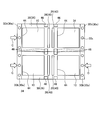
- Drawing 1 is a top view explaining the schematic structure of the storage battery unit which constitutes the storage battery device for vehicles concerning an embodiment.
- FIG. 2 is a side view for explaining a configuration of a battery box housed in a storage battery unit that constitutes the vehicle storage battery device according to the embodiment and a heat transport unit connected to the battery box.
- Drawing 3 is a side view explaining the state where the storage battery device for vehicles concerning an embodiment was arranged under the floor of vehicles.
- Drawing 4 is an explanatory view explaining the state where the storage battery device for vehicles concerning an embodiment was divided and arranged on the both sides of the vehicle width direction under the floor of a vehicle.
- Drawing 5 is an explanatory view explaining other examples which arrange the storage battery device for vehicles concerning an embodiment under the floor of vehicles.
- FIG. 2 is a side view for explaining a configuration of a battery box housed in a storage battery unit that constitutes the vehicle storage battery device according to the embodiment and a heat transport unit connected to the battery box.
- Drawing 3 is a side view explaining the state where the storage
- FIG. 6 is an explanatory diagram illustrating a fixing structure and a cooling fluid flow when the vehicle storage battery device according to the embodiment is fixed to a lower floor of the vehicle.
- FIG. 7 is an explanatory view illustrating a fixing structure when the vehicle storage battery device according to the embodiment is fixed to the upper part of the roof of the vehicle, and the flow of the cooling fluid.
- FIG. 8 is a diagram illustrating a structure of an exterior case that can be selected to be fixed to the upper part of the roof or fixed to the lower part of the vehicle storage battery device according to the embodiment, and is a diagram illustrating an aspect of fixing to the lower part of the floor.
- FIG. 9 is a diagram showing a structure of an exterior case that can be selected to be fixed to the upper part of the roof and fixed to the lower part of the vehicle storage battery device according to the embodiment, and is a view showing an aspect of fixing to the upper part of the roof.
- FIG. 10 is a top view of the outer case of the vehicle storage battery device according to the embodiment.
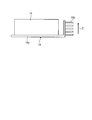
- FIG. 1 is a plan view illustrating a schematic configuration of a storage battery unit 10 constituting the vehicle storage battery device according to the embodiment.
- FIG. 2 is a side view for explaining the configuration of the single battery housed in the storage battery unit 10 and the heat transport section 18 connected to the single battery.
- the storage battery unit 10 supports a plurality of battery boxes 14 in which a single battery serving as a power source for the vehicle is housed in a substantially rectangular housing 12.
- the vehicle may be, for example, an electric locomotive that travels by driving a drive source (motor) with electric power of the storage battery unit 10, or a hybrid locomotive having a motor and an engine as drive sources.
- the storage battery unit 10 may be a passenger car such as an electric vehicle or a hybrid vehicle, a truck, a bus or the like.
- the electric power of the storage battery unit 10 may be supplied to an electric system (auxiliary device) of the vehicle.
- the storage battery unit 10 may be used for an electrical system of a vehicle whose drive source is only an engine.
- FIG. 1 shows an example in which six storage chambers 12e are defined. That is, in this embodiment, six battery boxes 14 are arranged in groups of three with a common cooling flow path 16 described later interposed therebetween. Each battery box 14 is arranged in the storage chamber 12e so that it is not substantially exposed to the outside air. As a result, the battery box 14 can be substantially prevented from coming into contact with dust, dirt, moisture, or the like.
- the material constituting the housing 12 is only required to ensure a predetermined level of rigidity, dustproof property, dripproof property, vibration resistance, etc. determined in advance in the design stage, for example, resin (plastic etc.) or metal. .
- the battery box 14 for example, a plurality of single cells (battery, single cell unit, single cell, not shown) connected in series or in parallel are stored.
- the single battery can be configured as, for example, a secondary battery (storage battery, rechargeable battery).
- the battery box 14 has a sensor (not shown) for detecting the voltage and temperature of the unit cell accommodated therein.
- the battery box 14 has electrode terminals (a positive terminal and a negative terminal) that are electrically connected to the internal cells, and the single cells in the adjacent battery boxes 14 are illustrated. They are electrically connected directly or in parallel via omitted wiring.
- the plurality of electrically connected single cells are electrically connected to a circuit breaker, a battery management system, or the like housed in a device housing described later, thereby realizing charge / discharge control.
- Each single cell can be configured as, for example, a lithium ion secondary battery.
- the single battery may be another secondary battery such as a nickel metal hydride battery, a nickel cadmium battery, or a lead storage battery.
- the battery box 14 includes a heat transport unit 18 that transports the heat generated inside the battery cell 14 to the outside by charging and discharging each unit cell.
- the heat transport unit 18 includes a heat pipe 18a that is thermally connected to a part of the battery box 14, for example, a lower surface, and a heat dissipating unit 18b that radiates heat transported by the heat pipe 18a.
- a heat pipe 18a for example, a volatile heat transport fluid sealed in an internal space of the pipe or an inner wall or the like impregnated can be used.
- the heat pipe 18 a may be directly connected to the bottom surface (wall surface) of the battery box 14.
- a plurality of grooves are formed in a metal plate-like member, and a heat transport fluid is passed through the groove, or the groove member is impregnated with the heat transport fluid. You may make it connect with the wall surface of the box 14.
- FIG. In this way, by using the heat pipe 18a, for example, heat transport can be efficiently carried out as compared with a case where a thermally conductive member such as a copper plate is attached to the battery box 14.
- maintenance and inspection are easier than water-cooled type.
- the heat radiating portion 18b can be a heat sink, for example. In the case of FIG. 2, the heat sink has a plate-like member arranged at a predetermined interval in the direction of arrow Z in FIG.
- the heat transport unit 18 including the heat pipe 18a and the heat sink has a simple structure, high robustness, and can realize efficient heat transport.
- a heat radiating fan may be used instead of the heat sink.
- the heat dissipating fan is connected or arranged at the end of the heat pipe 18a, and can forcibly form a heat flow to dissipate heat.
- the battery box 14 includes the heat transport unit 18, whereby the inside of the battery box 14 can be efficiently cooled.
- what put together the battery box 14 and the heat transport part 18 (heat pipe 18a, the thermal radiation part 18b) as shown in FIG. 2 may be called a subpack.
- a common cooling channel 16 is formed inside the housing 12.
- the common cooling channel 16 crosses substantially the center of the housing 12, and passes through the suction port 16 a for taking in the cooling fluid and the channel inner region A (inside the channel) at both ends thereof.
- a discharge port 16b for discharging the fluid is provided.
- outside air air
- the suction port 16a and the discharge port 16b are formed to open in a direction different from the traveling direction of the vehicle on which the storage battery unit 10 is mounted.
- the heat transport portions 18 heat radiation portions 18 b
- the plurality of battery boxes supported by the housing 12 are exposed to the flow path inner region A.
- FIG. 1 although the example which forms the common cooling flow path 16 using the inner wall 12c of the housing 12, the bottom wall 12d, and an upper surface wall is shown, it does not restrict to this but the cylindrical common formed separately
- the cooling channel 16 may be disposed inside the housing 12.
- the common cooling flow path 16 has a substantially straight shape with no branching, a decrease in flow velocity (wind speed, wind power) can be reduced, which can contribute to an improvement in cooling efficiency.
- a simple structure cooling structure can be realized, and the robustness of the cooling structure is improved, and vibration resistance, dust resistance, and drip resistance are improved. A high structure can be obtained.
- a blower fan 20 that functions as a fluid transfer device is disposed in the vicinity of the suction port 16 a of the common cooling flow path 16, for example, the suction port 16 a, and external air as a cooling fluid is supplied.
- the air is actively sent into the flow path inner area A of the common cooling flow path 16.
- a filter device 22 supported by the suction side sub-housing 12f is disposed on the upstream side of the blower fan 20.
- a seal member 24 such as packing is disposed at the connection portion between the suction side sub-housing 12f and the side wall 12b of the housing 12, and prevents outside air (cooling fluid) that does not pass through the filter device 22 from flowing into the suction port 16a side. is doing.
- the sealing member 24 is doubled to improve connection reliability.
- the filter device 22 of the present embodiment is disposed at a position (displaced position) deviated from the front side of the suction fan 20 or the suction port 16a.
- the two filter devices 22 are separately arranged so as not to be positioned in front of the blower fan 20 or the suction port 16a.
- the outside air (air) that has passed through the filter device 22 flows into the blower fan 20 or the suction port 16a through the suction flow path R formed by the partition wall 12a and the suction side sub-housing 12f.
- the suction force of the blower fan 20 with respect to the filter device 22 by disposing the filter device 22 away from the front side of the blower fan 20 as shown in FIG. can be dispersed.
- the suction force by the blower fan 20 is likely to act on a specific portion on the filter device 22, and the contamination due to dust or the like contained in the outside air is partially generated. There is a case to let you. In such a case, the function of the filter device 22 may be reduced or the life may be shortened.
- the partial contamination of the filter device 22 as described above can be reduced or suppressed. That is, the life of the filter device 22 can be extended and the maintenance frequency can be reduced.
- the filter device 22 only needs to be able to remove foreign matters such as dust and dust, moisture, and the like so that the flow passage inner region A of the common cooling flow passage 16 and the blower fan 20 can maintain a predetermined cleanliness, and various filter structures can be selected. It can. For example, a single layer type or a multilayer type may be used. In the case of a multilayer type, for example, a combination of an inertia filter and a cloth filter may be used.
- the discharge port 16b is formed to open in a direction different from the traveling direction of the vehicle.
- the discharge port 16b of the common cooling channel 16 is disposed at a position (straight position) on the extension line of the suction port 16a.
- the fluid discharged from the discharge port 16b is discharged to the back side of the drawing in FIG.
- the discharge side sub-housing 12 g connected to the housing 12 via the seal member 24 has a plurality of discharge holes 26 formed in one direction (for example, the back side of the paper in FIG. 1).
- the discharge hole 26 opens in a direction different from the traveling direction of the vehicle.
- the shape of the discharge hole 26 shown in FIG. 1 is an example, and a square hole or the like may be used, or the entire formation surface or a part thereof may have a mesh structure. Moreover, it is good also as a slit shape or the large hole (a long hole, a square long hole, etc.) which made the discharge hole 26 substantially continuous.
- the discharge hole 26 may be provided with a filter or an equivalent to prevent entry of foreign matter from the outside.
- the storage battery unit 10 as described above may be used as, for example, a power supply unit for a railway vehicle.
- the traveling direction may be reversed between the forward path and the return path.
- the suction port 16a filter device 22
- the wind is a head wind in the forward path, so that the outside air (cooling fluid) is more efficiently discharged than the suction force of the blower fan 20.
- the outside air flows from the discharge port 16b (discharge hole 26) into the flow path inner area A of the common cooling flow path 16, and the discharge efficiency of the external air from the flow path inner area A decreases. That is, there is a difference in the discharge capacity between the forward path and the return path. As a result, regarding the discharge of the cooling fluid, the cooling capacity is different between the forward path and the return path.
- the opening direction of the suction port 16a of the common cooling channel 16 (the outside air intake direction S of the filter device 22) and the opening direction of the discharge port 16b (the opening direction of the discharge hole 26) are In either case, the opening is made in a direction different from the traveling direction of the railway vehicle.
- the suction port 16a (filter device 22) is directed in the vehicle width direction (side) of the railway vehicle. In this way, by directing the suction port 16a (filter device 22) to the side of the railway vehicle, it is possible to stably take in outside air regardless of the traveling direction of the railway vehicle. That is, a difference in outside air intake efficiency is unlikely to occur between the outward path and the return path.
- the outside air can be stably discharged regardless of the traveling direction of the railway vehicle.
- the cooling efficiency of the storage battery unit 10 is made equal, and stable cooling of the storage battery unit 10 is realized.
- the storage battery unit 10 configured as described above may be mounted on a railway vehicle as a single-layer unit that supports six battery boxes 14 as shown in FIG. You may mount in a rail vehicle as a lamination
- the filter apparatus 22 When it is set as a lamination
- the discharge hole 26 should just be provided corresponding to the lowermost layer of a lamination
- the storage battery unit 10 of the present embodiment is an air cooling cooling system that takes outside air as a cooling fluid into the common cooling flow path 16.
- the air-cooled cooling structure of the present embodiment is simpler and more robust than the water-cooled cooling structure. It is possible to suppress the occurrence of malfunctions and breakage of the cooling structure due to.
- 3, 4, and 5 are side views for explaining a state in which the storage battery unit 10 as described above is disposed under the floor of a railway vehicle 28 that is an example of a vehicle.
- the storage battery unit 10 arranges the filter device 22 in the vehicle width direction (side surface) of the railway vehicle 28, thereby taking in stable outside air (cooling fluid) regardless of the traveling direction of the railway vehicle 28. Is possible.
- the storage battery unit 10 is supported by the exterior case 30 and fixed to the railway vehicle 28. Details of the exterior case 30 will be described later.
- 3 to 5 show examples in which a plurality of storage battery units 10 are arranged side by side in close proximity.
- the assembly of the storage battery units 10 supported by the exterior case 30 can be fixed in the space between the carriages 32 before and after the railcar 28.
- various devices are arranged under the floor of the railway vehicle 28. Therefore, the storage battery unit 10 can be supported by an individual outer case 30 arranged in a state separated into the left and right in the vehicle width direction of the railway vehicle 28 as shown in FIG. 4 according to the arrangement of other devices. it can.
- the outer case 30 is provided with a linear support section so as to support a plurality of the storage battery units 10 (housing 12) along the vehicle traveling direction. The support section will be described later.
- FIG. 1 In the case of the layout of the storage battery unit 10 as shown in FIG.
- the outside air taken in from the side of the railway vehicle 28 may be discharged downward of the vehicle as indicated by the discharge hole 26.
- the discharge hole 26 since there is a gap in the vehicle width direction between the exterior cases 30 arranged on the left and right in the vehicle width direction, the discharge hole 26 may be arranged toward this gap.
- the discharge hole 26 can be linearly arranged with respect to the flow path inner region A of the common cooling flow path 16 (see FIG. 1), the discharge resistance can be reduced, and the cooling efficiency can be improved.
- the position of the discharge hole 26 of the storage battery unit 10 supported by the left outer case 30 in the vehicle width direction and the position of the discharge hole 26 of the storage battery unit 10 supported by the right outer case 30 in the vehicle width direction are shifted. Further, it is possible to reduce the occurrence of exhaust in the gap between the exterior cases 30 arranged on the left and right in the vehicle width direction.
- the plurality of storage battery units 10 are collectively supported by the outer case 30.
- the exterior case 30 is provided with a linear support section so as to support a plurality of storage battery units 10 (housings 12) along the vehicle traveling direction.
- the outside air taken in from the side of the railway vehicle 28 is discharged downward of the vehicle as indicated by the discharge hole 26.
- the discharge of the cooling fluid by opening the discharge hole 26 in a direction different from the traveling direction of the railway vehicle 28, it is possible to discharge the outside air (cooling fluid) stably regardless of the traveling direction of the railway vehicle 28. It becomes.
- the filter device 22 in the storage battery unit 10 is disposed on the side surface of the railway vehicle 28 as shown in FIG. As described with reference to FIG. 1, the filter device 22 is supported by the suction side sub-housing 12 f, so that it can be easily detached from the side of the railway vehicle 28. Further, by removing the suction side sub-housing 12f, the blower fan 20 disposed on the suction port 16a side of the common cooling channel 16 can be easily accessed, and maintenance and replacement work can be facilitated. Furthermore, the storage battery unit 10 itself can be easily attached / detached by accessing from the side of the railway vehicle 28 as necessary. As described above, the filter device 22 having a relatively short maintenance interval can be easily replaced, so that the maintenance and inspection work of the storage battery unit 10 can be performed efficiently.
- the storage battery unit 10 requires various electrical components in order to perform charge / discharge control, state management, and the like of a plurality of stored single cells.
- a cell management system that monitors the temperature of each battery box 14 and the charge / discharge state of a single cell, a substrate of the battery management system, and a circuit breaker for realizing an open contact operation between the main circuit and the single cell ( MCCB (Molded Case Circuit Breaker), service disconnector, etc.
- MCCB Molded Case Circuit Breaker
- a control circuit board, a circuit power supply, a safety device, various sensors such as a temperature sensor, a safety indicator lamp, a protection circuit board, an interlock mechanism, and the like are also included.
- These electric components can be arranged inside each storage battery unit 10, but can also be arranged collectively.
- these electric components are housed in a sealed device housing 34 having substantially the same shape and size as the housing 12 of the storage battery unit 10. Then, as shown in FIGS. 4 and 5, the device housing 34 is supported in the vicinity of the storage battery unit 10 using one of a plurality of support sections formed in the exterior case 30. As described above, the device housing 34 is supported by the outer case 30 in the same manner as the other storage battery units 10 (housing 12), so that the device housing 34 can be easily detached and attached, and has a life different from that of the unit cell. Maintenance of electrical equipment can be performed efficiently. Further, by storing the electrical components in the device housing 34, it is possible to substantially block the entry of outside air, and it is possible to reduce the occurrence of malfunctions of the electrical components due to the mixing of dust, dirt, and moisture.
- FIG. 6 and 7 are views when the railway vehicle 28 is viewed from the track direction, and a specific example in which the storage battery unit 10 (vehicle storage battery device) supported by the outer case 30 is fixed to the railway vehicle 28.
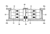
- FIG. FIG. 6 is an explanatory diagram for explaining the fixing structure when the storage battery unit 10 is fixed to the lower floor of the railway vehicle 28 and the flow of the cooling fluid.
- FIG. 7 is an explanatory diagram for explaining a fixing structure when the storage battery unit 10 is fixed to the upper part of the roof of the railway vehicle 28 and the flow of the cooling fluid.
- FIG. 6 is a configuration corresponding to FIG. 5, and a plurality of storage battery units 10 are collectively supported by the outer case 30.
- the exterior case 30 is formed with an underfloor fixing flange 30a (lower fixing portion) on the upper surface side so that it can be connected and fixed to an underfloor fixing base 28b formed on the underfloor 28a of the railway vehicle 28.
- the fastening of the underfloor fixing flange 30a and the underfloor fixing base 28b can be performed using, for example, a bolt or a nut.
- the storage battery units 10 are stacked in three layers, and the external air sucked from the filter device 22 is indicated by the arrows in FIG. 6, and the common cooling flow paths 16 (see FIG. 6) of the storage battery units 10 of each layer. 1). And it discharges out of the exterior case 30 through the discharge hole 26 which passed the discharge port 16b and opened to the vehicle downward direction.
- the intake air is not affected by the traveling direction of the railcar 28 in both cases. Therefore, it is possible to prevent a difference in the cooling efficiency in the storage battery unit 10 during the forward travel and the backward travel, and to realize efficient and stable cooling.
- the exterior case 30 is provided with a roof fixing flange 30b (upper fixing portion) on the lower surface side.
- the exterior case 30 is formed on the upper surface side of the ceiling 28d in the roof upper part B formed between the roof 28c for avoiding rain, snow and the like in the railway vehicle 28 and the ceiling 28d serving as a partition wall between the passenger compartment side.
- the roof top fixing base 28e and the roof top fixing flange 30b can be fastened. The fastening between the roof fixing flange 30b and the roof fixing base 28e can be performed using, for example, a bolt or a nut.
- the outside air (cooling fluid) taken into the storage battery unit 10 is performed from the side of the railway vehicle 28 via the filter device 22. Since the roof top B is covered with the roof 28c, the roof 28c in the vicinity of the filter device 22 is formed with a vent 28f so that outside air can easily enter and exit.
- the storage battery units 10 are laminated in three layers, and the external air sucked from the filter device 22 is indicated by the arrows in FIG. 7, and the common cooling flow paths 16 (see FIG. 7) of the storage battery units 10 of each layer. 1). And it is discharged out of the exterior case 30 through the discharge hole 26 that passes through the discharge port 16b and opens upward of the vehicle.
- the intake air is not affected by the traveling direction of the railcar 28 in both cases. Therefore, it is possible to prevent a difference in the cooling efficiency in the storage battery unit 10 during the forward traveling and the backward traveling, and to perform efficient and stable cooling.
- the cooling fluid (air) discharged from the discharge hole 26 can be discharged from the vent hole 28f. However, by providing a vent hole corresponding to the opening position of the discharge hole 26, the cooling fluid that has been used is used. It is possible to prevent the fluid (heated air) from being sucked from the filter device 22 again, thereby contributing to the improvement of the cooling efficiency.
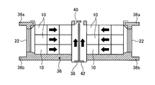
- FIGS. 8 and 9 are diagrams for explaining a modification of the above-described exterior case 30.
- FIG. The exterior case 36 shown in FIGS. 8 and 9 is a common exterior case applicable to both the underfloor fixing described in FIG. 6 and the on-roof fixing described in FIG.
- the basic structure of the exterior case 36 is the same as that of the exterior case 30 shown in FIGS. 6 and 7. However, in the case of the exterior case 36, an underfloor fixing flange 36 a (lower fixing portion) and an on-roof fixing flange 36 b ( Both upper fixing part).
- the outer case 36 is fixed by the lower opening planned portion 38 for discharging the cooling fluid to the lower side of the vehicle and the roof fixing flange 36b.
- an upper opening scheduled portion 40 for discharging a cooling fluid to the upper side of the vehicle.
- One of the upper opening scheduled portion 40 and the lower opening scheduled portion 38 is closed by the closing member 42 when not in use.
- FIG. 8 shows an application example of the closing member 42 when the outer case 36 is fixed under the floor of the railway vehicle 28.
- the upper opening scheduled portion 40 is closed by the closing member 42, and the lower opening scheduled portion 38 is in the open state. That is, the outside air for cooling sucked in from the filter device 22 passes through the common cooling flow path 16 (see FIG. 1) of the storage battery unit 10 and is discharged from the non-closed lower opening planned portion 38 to the lower side of the vehicle. become. That is, when the exterior case 36 is fixed under the floor, the used cooling fluid does not flow to the floor surface side where the discharge efficiency is lowered due to the presence of the underfloor 28a.
- FIG. 9 shows an application example of the closing member 42 when the exterior case 36 is fixed to the roof top B of the railway vehicle 28.
- the lower opening scheduled portion 38 is closed by the closing member 42, and the upper opening scheduled portion 40 is in the open state. That is, the outside air for cooling sucked from the filter device 22 passes through the common cooling flow path 16 (see FIG. 1) of the storage battery unit 10 and is discharged upward from the non-closed upper opening scheduled portion 40 toward the upper side of the vehicle. Will be.
- the used cooling fluid is prevented from flowing to the ceiling surface side where the discharge efficiency is lowered due to the presence of the ceiling 28d.
- the blocking member 42 may be any member that prevents the flow of the cooling fluid, and may be composed of, for example, a metal plate or a resin plate.
- a mesh plate or the like is attached to the non-occluded side, that is, the lower opening planned portion 38 or the upper opening planned portion 40 where the closing member 42 is not mounted, in order to prevent foreign matter or the like from entering the discharge port side. It may be.
- a mesh plate may be attached to the lower opening scheduled portion 38 and the upper opening scheduled portion 40 so that the side that needs to be closed is closed by the closing member 42.
- the lower opening planned portion 38 and the upper opening planned portion 40 are closed by an integral part of the exterior case 36 in the initial state, and the lower opening planned portion 38 or the upper opening planned portion 40 on the side to be in the non-closed state is provided.
- the blocked parts may be excluded (removed or broken).
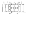
- FIG. 10 is a top view of the outer case 30 (outer case 36) for fixing on the roof.
- the exterior case 30 (exterior case 36) is a box-shaped frame made of, for example, metal, and is provided with a plurality of support sections 44 that support a plurality of housings 12 (storage battery units 10) arranged side by side.
- the storage battery unit 10 is inserted so as to drop from above the support section 44 and is supported by the outer case 30 (outer case 36).
- the storage battery unit 10 may be fixed to the outer case 30 (the outer case 36) using a fastening member such as a bolt.
- a fastening member such as a bolt.
- two exterior cases 30 having two support sections 44 are shown connected, but the number of support sections 44 is not limited to this, and may be one or three or more. .
- at least one of the plurality of support sections 44 is provided with a device housing 34 that houses an electrical component different from the unit cell. Accordingly, in FIG. 10, outside air is sucked into the storage battery unit 10 supported by the three support sections 44 as indicated by an arrow C, and the outside air is blocked in the remaining one support section 44 due to the presence of the device housing 34. It has become so.
- a roof fixing flange 30b is formed on both ends of the lower end of the outer case 30, a roof fixing flange 30b is formed.
- the exterior case 30 is fastened to the roof top fixing base 28e using the bolt holes 30c formed in the roof top fixing flange 30b.
- the underfloor fixing flange 30a can be seen in the top view.
- a discharge hole 26 (upper opening planned portion 40 in the case of the outer case 36) for discharging a cooling fluid to the upper side of the roof is formed.
- the discharge holes 26 (upper opening scheduled portions 40) are formed in a long hole shape with two strips. A mesh plate may be provided in the discharge hole 26 (the upper opening scheduled portion 40).
- the exterior case 30 (the exterior case 36) is provided with a plurality of reinforcing members 46 that extend, for example, in the direction perpendicular to the paper surface in order to ensure frame rigidity.
- the support sections 44 are arranged in the vehicle width direction.
- FIG. 4 when the exterior case 30 (exterior case 36) is arranged separately on both sides in the vehicle width direction of the railway vehicle 28, a plurality of linear cases are formed along the traveling direction of the railway vehicle 28.
- the support section 44 may be arranged. In that case, when connecting the some exterior case 30, it will connect along the advancing direction of the railcar 28. FIG.
- the exterior case 30 (exterior case 36) having the support section 44 the storage battery unit 10 and the device housing 34 can be reliably supported.
- vibration resistance can be easily improved by interposing, for example, a vibration isolating member or the like at the contact portion between them.
- the vehicle storage battery device of this embodiment includes the housing 12, the plurality of battery boxes 14, and the common cooling flow path 16.
- the battery box 14 is disposed inside the housing 12 and has a heat transport portion 18 that houses a single battery serving as a power source for the vehicle and transports heat generated inside the battery box 14 to the outside of the battery box 14.
- the common cooling flow path 16 is disposed inside the housing 12 and has a suction port 16a for taking in fluid and a discharge port 16b for discharging the fluid that has passed through the flow path, and opens in a direction different from the traveling direction of the vehicle.
- Each heat transport portion 18 of the battery box 14 is exposed inside the flow path. According to this configuration, for example, heat generated by repeated charge and discharge can be efficiently discharged, and the battery can be effectively cooled.
- outside air as a cooling medium flows through the common cooling flow path 16 and comes into contact with only a part of the heat transport section 18. That is, the outside air as the cooling medium is not in contact with the single cells in the battery box 14.
- the electrical parts including the battery can avoid contact with dust, moisture, and the like as much as possible, so that the battery can be prevented from being contaminated.
- the plurality of heat radiating portions 18b in the common cooling flow path 16 a simple structure cooling structure can be realized, and the robustness of the cooling structure can be improved.
- the cooling fluid intake port 16a and the exhaust port 16b are opened in a direction different from the traveling direction of the railway vehicle 28, the stable outside air (cooling fluid) regardless of the traveling direction of the railway vehicle 28. Can be inhaled and discharged. As a result, the same level of efficient cooling can be realized in the forward traveling and the backward traveling of the railway vehicle 28.
- the discharge port 16b of the vehicle storage battery device of the present embodiment may discharge the fluid, for example, either above or below the vehicle. According to this configuration, for example, fluid discharge can be stably performed regardless of the traveling direction of the vehicle, so that variation in cooling efficiency depending on the traveling direction can be suppressed.
- the vehicle storage battery device of the present embodiment may include, for example, exterior cases 30 and 36 provided with a plurality of support sections 44 that support a plurality of housings 12 arranged side by side. According to this configuration, for example, the plurality of storage battery units 10 can be stably supported. Moreover, since a support aspect is made common, attachment / detachment of the storage battery unit 10 becomes easy, and it can contribute to improvement of maintainability.
- a device housing 34 that houses an electrical component different from the unit cell is disposed in at least one of the plurality of support sections 44 of the exterior cases 30 and 36. It may be. According to this configuration, since the electrical components that drive or maintain the storage battery unit 10 can be individually stored and separated from the cooling structure of the storage battery unit 10, dust and dust that may be contained in the cooling fluid, Electrical components can be protected from moisture and the like.
- the exterior case 36 of the vehicle storage battery device of the present embodiment includes an on-roof fixing flange 36b (upper fixing portion) for fixing to the upper portion of the roof of the vehicle and an under-floor fixing for fixing to the lower portion of the floor of the vehicle.
- an on-roof fixing flange 36b upper fixing portion
- an under-floor fixing for fixing to the lower portion of the floor of the vehicle.
- either one of the upper opening planned portion 40 and the lower opening planned portion 38 of the vehicle storage battery device of the present embodiment may be prevented from being discharged by the closing member 42, for example.
- the vehicle storage battery device can be easily changed to an applicable form by the closing member 42 regardless of whether it is installed on the roof of the vehicle or under the floor. As a result, it is possible to contribute to simplification of assembly work using common parts and reduction of manufacturing costs.
- the support sections 44 may be provided linearly so as to support a plurality of housings 12 along the vehicle traveling direction in the outer cases 30 and 36.
- the access direction with respect to the housing 12 and the device housing 34 supported by the outer cases 30 and 36 can be made constant. As a result, the maintainability of the storage battery unit 10 and the electrical parts is improved, and maintenance inspection can be easily performed.
- the heat transport part 18 of the vehicle storage battery device of the present embodiment includes a heat pipe 18a thermally connected to the wall surface of the battery box 14, and a common cooling flow thermally connected to one end of the heat pipe 18a. You may make it comprise with the thermal radiation part 18b exposed to the inside of the path
- the vehicle storage battery device of the present embodiment includes, for example, a filter device 22 disposed at a position deviated from the front side of the suction port 16a, a suction flow path R that connects the filter device 22 and the suction port 16a, and May be further provided.
- a filter device 22 disposed at a position deviated from the front side of the suction port 16a
- a suction flow path R that connects the filter device 22 and the suction port 16a
Landscapes
- Engineering & Computer Science (AREA)
- Chemical & Material Sciences (AREA)
- General Chemical & Material Sciences (AREA)
- Electrochemistry (AREA)
- Chemical Kinetics & Catalysis (AREA)
- Manufacturing & Machinery (AREA)
- Power Engineering (AREA)
- Mechanical Engineering (AREA)
- Transportation (AREA)
- Sustainable Energy (AREA)
- Sustainable Development (AREA)
- Life Sciences & Earth Sciences (AREA)
- Aviation & Aerospace Engineering (AREA)
- Secondary Cells (AREA)
- Battery Mounting, Suspending (AREA)
- Electric Propulsion And Braking For Vehicles (AREA)
- Arrangement Or Mounting Of Propulsion Units For Vehicles (AREA)
Abstract
本発明は、充放電が繰り返されることにより発生する熱を排出する車両用蓄電池装置を提供するものである。 車両用蓄電池装置(10)は、ハウジング(12)と、ハウジングの内部に配置され、車両の電源となる単電池を収納する電池箱であって、電池箱の内部で発生した熱を電池箱の外部に輸送する熱輸送部を有する複数の電池箱(14)と、ハウジングの内部に配置されて、流体を取り入れる吸入口(16a)及び流路内部を通過した流体を排出する排出口(16b)が車両の走行方向とは異なる方向に開口すると共に、複数の電池箱のそれぞれの熱輸送部が流路内部に露出された共通冷却流路(16)と、を備える。
Description
本発明の実施形態は、車両用蓄電池装置に関する。
従来、ハウジングと、ハウジング内に配置された電池と、電池に冷却用空気を当てることにより電池等を冷却する冷却装置を備えた電力貯蔵装置(電源装置、電池装置)が知られている。
この種の電池装置を車両に搭載して使用する場合、充放電が繰り返されることにより発生する熱を効率的に排出して電池を冷却する堅牢性の高い冷却構造が必要である。また、冷却媒体として外気を用いる場合、電池や配線等を含む電気部品は、塵や水分等との接触を極力避けるように電池装置を構成することが望ましい。
実施形態にかかる車両用蓄電池装置は、例えば、ハウジングと、複数の電池箱と、共通冷却流路と、を備える。複数の電池箱は、ハウジングの内部に配置され、車両の電源となる単電池を収納する。また、電池箱は、当該電池箱の内部で発生した熱を電池箱の外部に輸送する熱輸送部を有する。共通冷却流路は、ハウジングの内部に配置されて、流体を取り入れる吸入口及び流路内部を通過した流体を排出する排出口が車両の走行方向とは異なる方向に開口する。また、共通冷却流路は、複数の電池箱のそれぞれの熱輸送部が流路内部に露出されている。
以下の例示的な実施形態や変形例には、同様の構成要素が含まれている。よって、以下では、同様の構成要素には共通の符号が付されるとともに、重複する説明が省略される。
図1は、実施形態にかかる車両用蓄電池装置を構成する蓄電池ユニット10の概略構成を説明する平面図である。また、図2は、蓄電池ユニット10に収納される単電池と、単電池に接続された熱輸送部18の構成を説明する側面図である。なお、蓄電池ユニット10は、図1に示すように、略方形のハウジング12の内部に、車両の電源となる単電池を収納する複数の電池箱14を支持している。車両は、例えば、蓄電池ユニット10の電力によって駆動源(モータ)を駆動することにより走行する電気機関車や、駆動源としてモータとエンジンを有したハイブリッド機関車であってもよい。また、電気自動車、ハイブリッド自動車等の乗用車、トラック、バス等であってもよい。蓄電池ユニット10の電力は、車両の電装系(補器類)に電力を供給してもよい。また、蓄電池ユニット10は、駆動源がエンジンだけの車両の電装系用として使用されてもよい。
ハウジング12の内部には、複数の隔壁12aが形成され、側壁12b、内部壁12c及び底面壁12d、上面壁(不図示)により収納室12eを画成している。図1の場合、6個の収納室12eが画成されている例を示している。つまり、本実施形態では、6個の電池箱14が後述する共通冷却流路16を挟んで3個ずつ配列されている。各電池箱14は、収納室12e内に配置されることにより実質的に外気に晒されないようになってる。その結果、電池箱14が、塵や埃、水分等と接触することを実質的に防止できる。なお、ハウジング12を構成する素材は、予め設計段階等で定められた所定レベルの剛性、防塵性、防滴性、耐振動性等を確保できればよく、例えば、樹脂(プラスチック等)や金属でもよい。
電池箱14の内部には、例えば、直列または並列に接続された複数の単電池(電池、単電池部、単セル、図示せず)が収納されている。単電池は、例えば、二次電池(蓄電池、充電式電池)として構成されうる。また、電池箱14には、収納される単電池の電圧や温度を検出するセンサ(図示せず)を有する。図示を省略しているが、電池箱14には、内部の単電池と電気的に接続された電極端子(正極端子、負極端子)を有し、隣接する電池箱14の単電池同士が図示を省略した配線を介して直接または並列に電気的に接続されている。そして、電気的に接続された複数の単電池は、後述する機器ハウジングに収納される遮断器やバッテリマネージメントシステム等と電気的に接続されて充放電制御が実現される。
単電池は、例えば、それぞれ、リチウムイオン二次電池として構成されることができる。なお、単電池は、ニッケル水素電池や、ニッケルカドミウム電池、鉛蓄電池等、他の二次電池であってもよい。
図2に示すように、電池箱14は、収納した各単電池が充放電を行うことで内部に発生した熱を電池箱14の外部に輸送する熱輸送部18を備える。熱輸送部18は、電池箱14の一部、例えば下面部に熱的に接続されたヒートパイプ18aと、当該ヒートパイプ18aにより輸送された熱を放熱する放熱部18bとで構成されている。ヒートパイプ18aは、例えば揮発性の熱輸送流体をパイプの内部空間に封入したり、内壁等に含浸させたものを利用できる。ヒートパイプ18aは電池箱14の底面(壁面)に直接接続するようにしてもよい。また、例えば、金属製の板状部材に複数の溝を形成し、その溝の中に熱輸送流体を通すまたは、その溝に熱輸送流体を含浸させるような構造として、その板状部材を電池箱14の壁面に接続させるようにしてもよい。このように、ヒートパイプ18aを用いることにより、例えば、銅板等の熱伝導性のある部材を電池箱14に貼り付ける場合に比べて効率的に熱輸送ができる。また、水冷式等に比較して、保守点検が容易である。放熱部18bは、例えばヒートシンクとすることができる。図2の場合、ヒートシンクは、板状部材を図2中矢印Z方向に所定の間隔を開けて配列している。なお、ヒートシンクの配置は一例であり、板状部材を図2の紙面裏面方向(矢印Z方向と直交する方向)に配列してもよい。このように、ヒートパイプ18aとヒートシンクで構成される熱輸送部18は構造がシンプルであり堅牢性が高く、効率的な熱輸送を実現できる。また、放熱部18bとして、ヒートシンクに代えて、放熱ファンを用いてもよい。この場合、放熱ファンは、ヒートパイプ18aの端部に接続または配置され、強制的に熱の流れを形成して放熱することができる。このように、電池箱14が熱輸送部18を備えることにより、電池箱14内部の冷却を効率的に行うことができる。なお、図2に示すような、電池箱14、熱輸送部18(ヒートパイプ18a、放熱部18b)をまとめたものをサブパックと称する場合もある。
ハウジング12の内部には、共通冷却流路16が形成されている。図1の場合、共通冷却流路16は、ハウジング12のほぼ中央部を横断し、その両端部に、冷却用の流体を取り入れる吸入口16a及び流路内部領域A(流路内部)を通過した流体を排出する排出口16bを備える。冷却用の流体としては、例えば外気(空気)を利用することができる。なお、吸入口16a及び排出口16bは、当該蓄電池ユニット10を搭載する車両の走行方向とは異なる方向に開口するように形成されている。また、共通冷却流路16は、ハウジング12が支持する複数の電池箱のそれぞれの熱輸送部18(放熱部18b)が流路内部領域Aに露出させている。図1の場合、ハウジング12の内部壁12c、底面壁12d及び上面壁を用いて共通冷却流路16を形成する例を示しているが、これに限らず、個別に形成された筒状の共通冷却流路16をハウジング12内部に配置するようにしてもよい。
共通冷却流路16の流路内部領域Aに熱輸送部18の放熱部18bを露出させる場合、内部壁12cに開口部を開け、その開口部を介して放熱部18bを流路内部領域A側に突出(露出)させる。この場合、開口部の周縁にシール部材等を配置し、共通冷却流路16の流路内部領域Aを流通する流体(例えば、外気)が収納室12e側に漏れ出さないようにしている。このように、共通冷却流路16の流路内部領域Aに、各電池箱14から輸送した熱を放熱部18bを露出させることにより、熱交換を効果的に行うことができる。また、図1に示すように、共通冷却流路16を挟んで両側に電池箱14を配置することにより複数の電池箱14から輸送される熱を集約して共通冷却流路16で熱交換することが可能になり、効率的な冷却を行うことができる。また、共通冷却流路16に複数の放熱部18bを集約することにより、ハウジング12内のスペース効率が向上する。さらに、単電池が収納される領域と外気が通過する共通冷却流路16内の領域を実質的に分離することができるので、単電池等の電装品の汚損を軽減できる。つまり、電装品の故障の発生頻度を低減、または故障の発生を防止することができる。さらに、共通冷却流路16を実質的に分岐のない、直線形状とすることで、流速(風速、風力)の低下を軽減できるので冷却効率向上に寄与できる。また、共通冷却流路16に複数の放熱部18bを集約させることで、シンプル構成の冷却構造が実現できて、当該冷却構造の堅牢性が向上すると共に、耐振動性、防塵、防滴性の高い構造を得ることができる。
図1に示す蓄電池ユニット10の場合、共通冷却流路16の吸入口16aの近傍、例えば、吸入口16aに流体搬送装置として機能する送風ファン20を配置して、冷却用の流体としての外気を積極的に共通冷却流路16の流路内部領域A内に送り込んでいる。また、送風ファン20の上流側には、吸入側サブハウジング12fに支持されたフィルタ装置22が配置されている。吸入側サブハウジング12fとハウジング12の側壁12bとの接続部にはパッキン等のシール部材24が配置され、フィルタ装置22を通過しない外気(冷却用の流体)が吸入口16a側に流れ込むことを防止している。図1の場合、シール部材24は2重に配置されて接続信頼性を向上している。
ところで、本実施形態のフィルタ装置22は、送風ファン20または吸入口16aの吸い込み側正面から外れた位置(ずれた位置)に配置されている。図1の場合、2個のフィルタ装置22が送風ファン20または吸入口16aの正面に位置しないように分離して配置されている。フィルタ装置22を通過した外気(空気)は、隔壁12aと吸入側サブハウジング12fとで形成される吸入流路Rを介して送風ファン20または吸入口16aに流れ込む。特に、送風ファン20を吸入口16aに設ける場合、図1のようにフィルタ装置22を送風ファン20の吸い込み側正面から外れた位置に配置することにより、フィルタ装置22に対する送風ファン20の吸引力(吸気力)を分散することができる。例えば、送風ファン20の吸入側正面にフィルタ装置22を配置した場合、送風ファン20による吸引力がフィルタ装置22上の特定部分に作用し易く、外気に含まれる埃等による汚染を部分的に生じさせてしまう場合がある。このような場合、フィルタ装置22の機能低下や寿命短縮を招いてしまう場合がある。図1に示すような送風ファン20とフィルタ装置22の配置による吸引力の分散を行うことにより、上述のようなフィルタ装置22の部分的な汚染を緩和または抑制できる。つまり、フィルタ装置22の寿命を延ばしメンテナンス頻度の低減に寄与できる。
フィルタ装置22は、共通冷却流路16の流路内部領域Aや送風ファン20等が所定の清浄度を維持できるように塵や埃等の異物や水分等を除去できればよく、フィルタ構造は種々選択できる。例えば、一層タイプでもよいし、多層タイプでもよい。多層タイプの場合、例えば、慣性フィルタと布フィルタの組み合わせでもよい。
前述したように、排出口16bは、車両の走行方向とは異なる方向に開口するように形成されている。図1の場合、共通冷却流路16の排出口16bは、吸入口16aの延長線上の位置(直線位置)に配置されている。本実施形態の場合、蓄電池ユニット10を複数個近接配置する場合の流体の排出効率を考慮して、排出口16bから排出された流体は、図1において紙面裏側に排出されるようにしている。図1の場合、シール部材24を介してハウジング12に接続された排出側サブハウジング12gには、一方向側(例えば図1の紙面裏側方向)に複数の排出孔26が形成されている。この場合も排出孔26は、車両の走行方向とは異なる方向に開口するようにしている。なお、図1に示す排出孔26の形状は、一例であり、角孔等でもよいし、形成面全体または一部がメッシュ構造になっていてもよい。また、排出孔26を実質的に連続させたスリット形状または大形の孔(長孔、角長孔等)としてもよい。なお、排出孔26には、フィルタやそれに相当するものを設けて、外部からの異物の侵入を防止するようにしてもよい。
ところで、上述したような蓄電池ユニット10は、例えば鉄道車両用の電源ユニットとして利用する場合がある。鉄道車両の場合、路線を往復運転する場合があるので、往路と復路で進行方向が逆転する場合がある。例えば、吸入口16a(フィルタ装置22)が鉄道車両の進行方向に向けて開口されていた場合、往路では向かい風となるので送風ファン20の吸引力以上に効率的に外気(冷却用の流体)を取り入れることができる。逆に復路の場合、外気取り入れは送風ファン20の吸引力のみとなるので、往路と復路で吸引能力に差が生じる、つまり、往路と復路とで冷却能力に違いが生じてしまう。同様に、排出口16b(排出孔26)が鉄道車両の進行方向に向けて開口していた場合、往路では外気の流れが排出口16b側に向かうため効率的に空気(冷却に利用された外気)の排出ができる。逆に復路の場合、排出口16b(排出孔26)から外気が共通冷却流路16の流路内部領域Aに流れ込むことになり、流路内部領域Aからの外気の排出効率が低下する。つまり、往路と復路で排出能力に差が生じる、その結果、冷却用の流体の排出に関しても往路と復路とで冷却能力に違いが生じてしまう。そこで、本実施形態の蓄電池ユニット10は、共通冷却流路16の吸入口16aの開口方向(フィルタ装置22の外気取り入れ方向S)及び排出口16bの開口方向(排出孔26の開口方向)は、いずれも鉄道車両の走行方向とは異なる方向に開口するようにしている。例えば、吸入口16a(フィルタ装置22)を鉄道車両の車幅方向(側方)に向けている。このように吸入口16a(フィルタ装置22)を鉄道車両の側方に向けることにより、鉄道車両の進行方向に拘わらず外気の取り入れを安定的に行うことができる。つまり、往路と復路で外気の取り入れ効率に差が生じ難いようにしている。同様に、排出口16b(排出孔26)を例えば鉄道車両の車両上方または車両下方に向けて開口させることにより、鉄道車両の進行方向に拘わらず外気の排出を安定的に行うことができる。つまり、往路と復路で外気の排出効率に差が生じ難いようにしている。その結果、鉄道車両の進行方向に拘わらず、蓄電池ユニット10における冷却効率を同等として、安定的な蓄電池ユニット10の冷却を実現している。
上述のように構成される蓄電池ユニット10は、図1に示すような6個の電池箱14を支持する単層ユニットとして鉄道車両に搭載してもよいし、単層ユニットを複数段、図1の紙面裏面方向に積層した積層ユニットとして鉄道車両に搭載してもよい。積層ユニットとする場合、フィルタ装置22は各層に設けてもよいし、積層方向に長いフィルタ装置22を配置してもよい。また、積層ユニットとする場合、排出孔26は、積層ユニットの最下層または最上層の単層ユニットに対応して設ければよい。
上述したように、本実施形態の蓄電池ユニット10は、共通冷却流路16に冷却用の流体として外気を取り込む空冷冷却方式である。図1に示すように、本実施形態の空冷冷却構造は水冷冷却方式の構造に比べて、シンプルであり堅牢性が高いため、鉄道車両等のように運行中に常時振動を受ける場合でも振動衝撃による冷却構造の不具合や破損の発生が抑制できる。
図3、図4、図5は、上述したような蓄電池ユニット10を車両の一例である鉄道車両28の床下に配置した状態を説明する側面図である。前述したように蓄電池ユニット10はフィルタ装置22を鉄道車両28の車幅方向(側面)に向けて配置することにより、鉄道車両28の進行方向に関わりなく安定した外気(冷却用の流体)の取り入れが可能となる。本実施形態の場合、蓄電池ユニット10は、外装ケース30によって支持されて鉄道車両28に固定される。なお、外装ケース30の詳細は後述する。図3~図5では、複数の蓄電池ユニット10を近接した状態で並べて配置した例を示している。外装ケース30よって支持された蓄電池ユニット10の集合体は、鉄道車両28の前後の台車32の間の空間に固定することができる。なお、鉄道車両28の床下には、蓄電池ユニット10の他にも様々な機器が配置される。したがって、蓄電池ユニット10は、他の機器の配置に応じて、図4に示すように、鉄道車両28の車幅方向の左右に分離した状態で配置された個別の外装ケース30で支持することができる。この場合、外装ケース30には、蓄電池ユニット10(ハウジング12)を車両進行方向に沿って複数個支持するように直線状に支持区画が設けられている。支持区画に関しては後述する。図4に示すような蓄電池ユニット10のレイアウトの場合、鉄道車両28の側方から取り入れた外気は、排出孔26が示すように、車両下方に排出するようにしてもよい。また、図4の例の場合、車幅方向左右に配置された外装ケース30の間に車幅方向の隙間があるため、この隙間に向けて排出孔26を配置するようにしてもよい。この場合、共通冷却流路16(図1参照)の流路内部領域Aに対して排出孔26を直線的に配置できるので、排出抵抗の低減が可能となり冷却効率の向上に寄与できる。なお、この場合、車幅方向左右の外装ケース30で支持された蓄電池ユニット10の排出孔26が対向しないようにすることが望ましい。例えば、車幅方向左の外装ケース30で支持された蓄電池ユニット10の排出孔26と車幅方向右の外装ケース30で支持された蓄電池ユニット10の排出孔26の位置をずらして配置することで、車幅方向左右に配置された外装ケース30の間の隙間に排気が籠もることが低減できる。
一方、図5の例の場合、複数の蓄電池ユニット10を外装ケース30によって一括的に支持している。この場合も外装ケース30には、蓄電池ユニット10(ハウジング12)を車両進行方向に沿って複数個支持するように直線状に支持区画が設けられている。図5に示すような蓄電池ユニット10のレイアウトの場合、鉄道車両28の側方から取り入れた外気は、排出孔26が示すように、車両下方に排出するようにする。冷却用の流体の排出に関しても排出孔26を鉄道車両28の走行方向とは異なる方向に開口させることにより、鉄道車両28の進行方向に関わりなく安定した外気(冷却用の流体)の排出が可能となる。
蓄電池ユニット10において、保守点検を必要とする部品の一つとしてフィルタ装置22がある。上述したように、本実施形態の場合、蓄電池ユニット10におけるフィルタ装置22は、図3に示すように鉄道車両28の側面に配置されている。図1で説明したように、フィルタ装置22は、吸入側サブハウジング12fに支持されているため、鉄道車両28の側方から容易に着脱可能である。また、吸入側サブハウジング12fを外すことにより、共通冷却流路16の吸入口16a側に配置された送風ファン20にも容易にアクセス可能となり、メンテナンスや交換作業が容易にできる。さらに、必要に応じて、蓄電池ユニット10自体の着脱も鉄道車両28の側方からのアクセスにより容易に実施可能である。このように、メンテナンス間隔が比較的短いフィルタ装置22の交換が容易にできることにより、蓄電池ユニット10の保守点検作業を効率的に行うことができる。
ところで、蓄電池ユニット10は、収納した複数の単電池の充放電制御や状態管理等を行うために種々の電気部品が必要になる。例えば、各電池箱14の温度や単電池の充放電状態の監視を実施するセルマネージメントシステムやバッテリマネージメントシステムの基板、主回路と単電池との間の開放接触動作を実現する配線用遮断器(MCCB;Molded Case Circuit Breaker)、サービスディスコネクタ等である。その他、制御回路の基板、回路用電源、保安装置、温度センサ等の各種センサ、安全表示灯、保護回路の基板、インターロック機構等も含まれる。これらの電気部品は、各蓄電池ユニット10の内部に配置することもできるが、一括して配置することもできる。本実施形態においては、これらの電気部品を蓄電池ユニット10のハウジング12と実質的に同じ形状、サイズの密閉型の機器ハウジング34に収めている。そして、機器ハウジング34を図4、図5に示すように、外装ケース30に形成された複数の支持区画のうちの1つを用いて蓄電池ユニット10の近傍に支持している。このように、機器ハウジング34を他の蓄電池ユニット10(ハウジング12)と同様に外装ケース30で支持することにより、機器ハウジング34の取り外しや装着が容易になり、単電池の寿命とは異なる寿命の電気機器のメンテナンスを効率的に行うことができる。また、電気部品を機器ハウジング34に収納することにより、外気の進入を実質的に遮断可能となり、塵や埃、水分の混入による電気部品の不具合の発生を低減することができる。
図6、図7は、鉄道車両28を線路方向からみた場合の図であり、外装ケース30に支持された蓄電池ユニット10(車両用蓄電池装置)を鉄道車両28に固定する場合の具体的な例を説明する図である。図6は、蓄電池ユニット10を鉄道車両28の床下部に固定する場合の固定構造と、冷却用の流体の流れを説明する説明図である。図7は、蓄電池ユニット10を鉄道車両28の屋根上部に固定する場合の固定構造と、冷却用の流体の流れを説明する説明図である。
図6は、図5に対応する構成で、複数の蓄電池ユニット10を外装ケース30によって一括的に支持している。外装ケース30には、上面側に床下固定用フランジ30a(下部固定部)が形成され、鉄道車両28の床下28aに形成された床下固定ベース28bに接続固定できるように構成されている。床下固定用フランジ30aと床下固定ベース28bとの締結は、例えばボルトまたはナット等を用いて実施することができる。外装ケース30を鉄道車両28の床下部に固定する場合、蓄電池ユニット10に取り込む外気(冷却用の流体)は鉄道車両28の側方からフィルタ装置22を介して行われる。図6の場合、蓄電池ユニット10は3層に積層され、フィルタ装置22から吸い込まれた外気が、図6中矢印で示されるように、各層の蓄電池ユニット10のそれぞれの共通冷却流路16(図1参照)を流通する。そして、排出口16bを通過し車両下方に開口した排出孔26を介して外装ケース30の外に排出される。前述したように、外気の取り入れは鉄道車両28の側方であり、外気の排出は車両下方なので、吸入及び排出のいずれの場合も鉄道車両28の進行方向による影響を受けない。したがって、往路走行時及び復路走行時の蓄電池ユニット10における冷却効率に差が生じることを防止し、効率的で安定した冷却を実現することができる。
図7は、図6の構成と同様に、複数の蓄電池ユニット10を外装ケース30によって一括的に支持している。外装ケース30には、下面側に屋根上固定用フランジ30b(上部固定部)が形成されている。外装ケース30は、鉄道車両28において雨、雪等を避けるための屋根28cと車室側との隔壁となる天井28dとの間に形成された屋根上部Bにおいて、天井28dの上面側に形成された屋根上固定ベース28eと屋根上固定用フランジ30bとが締結できるように構成されている。屋根上固定用フランジ30bと屋根上固定ベース28eとの締結は、例えばボルトまたはナット等を用いて実施することができる。外装ケース30を鉄道車両28の屋根上部Bに固定する場合、蓄電池ユニット10に取り込む外気(冷却用の流体)は鉄道車両28の側方からフィルタ装置22を介して行われる。屋根上部Bは屋根28cに覆われているので、フィルタ装置22の近傍の屋根28cには、通気口28fが形成され、容易に外気が出入りできるようになっている。図7の場合、蓄電池ユニット10は3層に積層され、フィルタ装置22から吸い込まれた外気が、図7中矢印で示されるように、各層の蓄電池ユニット10のそれぞれの共通冷却流路16(図1参照)を流通する。そして、排出口16bを通過し車両上方に開口した排出孔26を介して外装ケース30の外に排出される。前述したように、外気の取り入れは鉄道車両28の側方であり、外気の排出は車両下方なので、吸入及び排出のいずれの場合も鉄道車両28の進行方向による影響を受けない。したがって、往路走行時及び復路走行時の蓄電池ユニット10における冷却効率に差が生じることを防止し、効率的で安定した冷却を行うことができる。なお、排出孔26から排出された冷却用の流体(空気)は、通気口28fから排出可能であるが、排出孔26の開口位置に対応した通気口を設けることにより、利用済みの冷却用の流体(加熱された空気)が再度フィルタ装置22から吸い込まれることを抑制して、冷却効率の向上に寄与できる。
図8、図9は、前述した外装ケース30の変形例を説明する図である。図8、図9に示す外装ケース36は、図6で説明した床下固定と、図7で説明した屋根上固定との両方に適用可能な共通外装ケースである。外装ケース36の基本的な構造は、図6、図7で示す外装ケース30と同じであるが、外装ケース36の場合、床下固定用フランジ36a(下部固定部)及び屋根上固定用フランジ36b(上部固定部)の両方を有する。また、外装ケース36は、床下固定用フランジ36aにより固定される場合に、冷却用の流体を車両下方に排出するための下方開口予定部38と、屋根上固定用フランジ36bにより固定される場合に、冷却用の流体を車両上方に排出するための上方開口予定部40と、を備える。そして、上方開口予定部40と下方開口予定部38のいずれか一方は、非使用時に閉塞部材42によって閉塞されるようになっている。
図8は、外装ケース36を鉄道車両28の床下に固定する場合の閉塞部材42の適用例である。この場合、上方開口予定部40が閉塞部材42により閉塞され、下方開口予定部38が開口状態となる。つまり、フィルタ装置22から吸い込まれた冷却用の外気は、蓄電池ユニット10の共通冷却流路16(図1参照)を通過して、非閉塞の下方開口予定部38から車両下方に排出されることになる。つまり、外装ケース36の床下固定時には、床下28aの存在により排出効率が低下する床面側に利用済みの冷却用の流体が流れないようにしている。
図9は、外装ケース36を鉄道車両28の屋根上部Bに固定する場合の閉塞部材42の適用例である。この場合、下方開口予定部38が閉塞部材42により閉塞され、上方開口予定部40が開口状態となる。つまり、フィルタ装置22から吸い込まれた冷却用の外気は、蓄電池ユニット10の共通冷却流路16(図1参照)を通過して、非閉塞の上方開口予定部40から車両上方に向けて排出されることになる。つまり、外装ケース36の屋根上固定時には、天井28dの存在により排出効率が低下する天井面側に利用済みの冷却用の流体が流れないようにしている。
閉塞部材42は、冷却用の流体の流れを妨げるものであればよく、例えば金属板や樹脂板で構成することができる。また、非閉塞側、つまり閉塞部材42が装着されない下方開口予定部38または上方開口予定部40には、排出口側に異物等が混入することを防止するために、メッシュ板等を装着するようにしてもよい。また、下方開口予定部38及び上方開口予定部40にメッシュ板を装着しておき、閉塞が必要な側を閉塞部材42で閉塞するようにしてもよい。また、下方開口予定部38及び上方開口予定部40を初期の状態で外装ケース36と一体のパーツによって閉塞状態としておき、非閉塞状態にする側の下方開口予定部38または上方開口予定部40を閉塞しているパーツを排除(取り外し、破断)するようにしてもよい。
このように、床下固定と屋根上固定の両方に適用可能な外装ケース36を用いることにより部品の共通化により、製造コスト削減や組み付け作業の簡略化等に寄与できる。
図10は、屋根上固定用の外装ケース30(外装ケース36)の上面視図である。外装ケース30(外装ケース36)は、例えば金属で構成される箱形のフレームであり、ハウジング12(蓄電池ユニット10)を複数個並んだ状態で支持する複数の支持区画44が設けられている。例えば、支持区画44の上方から蓄電池ユニット10を落とし込むように挿入することで外装ケース30(外装ケース36)で支持される。また、蓄電池ユニット10は外装ケース30(外装ケース36)にボルト等の締結部材を用いて固定してもよい。図10の場合、2個の支持区画44を有する外装ケース30が2個連結された状態で示されているが、支持区画44の形成数はこれに限らず、1個でも3個以上でもよい。なお、図5で説明したように、複数の支持区画44のうち少なくとも一つに、単電池とは異なる電気部品を収納する機器ハウジング34が配置されるようになっている。したがって、図10において、3つの支持区画44に支持される蓄電池ユニット10には矢印Cで示すように外気が吸入され、残りの1つの支持区画44は機器ハウジング34の存在のため外気が遮断されるようになっている。外装ケース30の下端両端部には、屋根上固定用フランジ30bが形成されている。この屋根上固定用フランジ30bに形成されたボルト用孔30cを用いて、外装ケース30が屋根上固定ベース28eと締結が行われる。なお、外装ケース36の場合は、上面視図の場合、床下固定用フランジ30aが見える。また、外装ケース30における支持区画44と支持区画44との間には、冷却用の流体を屋根上方に排出するための排出孔26(外装ケース36の場合は上方開口予定部40)が形成されている。図10の場合、排出孔26(上方開口予定部40)は長孔形状で2条形成されている。排出孔26(上方開口予定部40)には、メッシュ板が設けられてもよい。外装ケース36を床下固定用として用いる場合は、図8に示すように上方開口予定部40が閉塞部材42によって閉塞されることになる。なお、外装ケース30(外装ケース36)は、フレーム剛性を確保するために、例えば紙面鉛直方向に延びる複数の補強部材46が配置されている。
図10に示す外装ケース30(外装ケース36)では、車幅方向に支持区画44を配列している例を示した。一方、図4に示すように鉄道車両28の車幅方向の両側に分離して外装ケース30(外装ケース36)を配置するような場合は、鉄道車両28の進行方向に沿って直線状に複数の支持区画44を配置するようにしてもよい。その場合、複数の外装ケース30を連結する場合は、鉄道車両28の進行方向に沿って連結することになる。このように、支持区画44を有する外装ケース30(外装ケース36)を用いることにより、蓄電池ユニット10や機器ハウジング34の支持を確実に行うことができる。また、外装ケース30(外装ケース36)により、蓄電池ユニット10や機器ハウジング34を支持する場合、両者の接触部分に例えば防振部材等を介在させることにより、耐振動性の向上が容易にできる。
上述したように、本実施形態の車両用蓄電池装置は、ハウジング12と、複数の電池箱14と、共通冷却流路16を備える。電池箱14は、ハウジング12の内部に配置され、車両の電源となる単電池を収納すると共に、電池箱14の内部で発生した熱を電池箱14の外部に輸送する熱輸送部18を有する。共通冷却流路16は、ハウジング12の内部に配置されて、流体を取り入れる吸入口16a及び流路内部を通過した流体を排出する排出口16b車両の走行方向とは異なる方向に開口すると共に、複数の電池箱14のそれぞれの熱輸送部18が流路内部に露出されている。この構成によれば、例えば、充放電が繰り返されることにより発生する熱を効率的に排出して、電池を効果的に冷却することができる。また、冷却媒体として外気は、共通冷却流路16の内部を流通し、熱輸送部18の一部としか接触しない。つまり、冷却媒体として外気は、電池箱14内の単電池とは非接触である。その結果、電池を含む電機部品は、塵や水分等との接触を極力避けることができるので、電池の汚損を抑制できる。また、共通冷却流路16に複数の放熱部18bを集約させることで、シンプル構成の冷却構造が実現できて、当該冷却構造の堅牢性を向上することができる。さらに、冷却用の流体の吸入口16a及び排出口16bを鉄道車両28の走行方向とは異なる方向に開口させているので、鉄道車両28の進行方向に関わりなく安定した外気(冷却用の流体)の吸入及び排出が可能となる。その結果、鉄道車両28の往路走行及び復路走行で同程度の効率的な冷却を実現できる。
また、本実施形態の車両用蓄電池装置の排出口16bは、例えば、流体を車両上方または車両下方のいずれか一方に排出するようにしてもよい。この構成によれば、例えば、車両の走行方向に関わりなく流体排出を安定して行うことができるので、走行方向による冷却効率のばらつきを抑制することができる。
また、本実施形態の車両用蓄電池装置は、例えば、ハウジング12を複数個並んだ状態で支持する複数の支持区画44が設けられる外装ケース30,36を備えてもよい。この構成によれば、例えば、複数の蓄電池ユニット10を安定的に支持することができる。また、支持態様が共通化されるので、蓄電池ユニット10の着脱が容易になりメンテナンス性の向上に寄与できる。
また、本実施形態の車両用蓄電池装置は、例えば、外装ケース30,36の複数の支持区画44のうち少なくとも一つに、単電池とは異なる電気部品を収納する機器ハウジング34が配置されるようにしてもよい。この構成によれば、蓄電池ユニット10を駆動または保守する電気部品を個別に収納して、蓄電池ユニット10の冷却構造とは分離できるので、冷却用の流体に含まれる可能性のある埃や塵、水分等から電気部品を保護することができる。
また、本実施形態の車両用蓄電池装置の外装ケース36は、車両の屋根上部に固定するための屋根上固定用フランジ36b(上部固定部)と、車両の床下部に固定するための床下固定用フランジ36a(下部固定部)と、屋根上固定用フランジ36bにより固定される場合に、流体を車両上方に排出するための上方開口予定部40と、床下固定用フランジ36aにより固定される場合に、流体を車両下方に排出するための下方開口予定部38と、を備えてもよい。この構成によれば、例えば、車両用蓄電池装置を車両の屋根上に設置する場合でも床下に設置する場合でも同一の外装ケース36の利用が可能になる。その結果、部品の共有化が可能になり、製造コスト削減や組立作業の簡略化に寄与できる。
また、本実施形態の車両用蓄電池装置の上方開口予定部40と下方開口予定部38のいずれか一方は、例えば、閉塞部材42によって流体の排出が妨げられるようにしてもよい。この構成によれば、例えば、車両用蓄電池装置を車両の屋根上に設置する場合でも床下に設置する場合でも閉塞部材42によって、容易に適用可能形態に変化させることができる。その結果、共通部品を用いた組立作業の簡略化、製造コスト削減に寄与できる。
また、本実施形態の車両用蓄電池装置は、例えば、外装ケース30,36にハウジング12を車両進行方向に沿って複数個支持するように直線状に支持区画44が設けられてもよい。この構成によれば、例えば、外装ケース30,36が支持するハウジング12や機器ハウジング34に対するアクセス方向を一定方向にすることができる。その結果、蓄電池ユニット10や電気部品のメンテナンス性が向上し、保守点検を容易に実施することができる。
また、本実施形態の車両用蓄電池装置の熱輸送部18は、電池箱14の壁面に熱的に接続されたヒートパイプ18aと、当該ヒートパイプ18aの一端に熱的に接続されて共通冷却流路16の内部に露出する放熱部18bとで構成されるようにしてもよい。この構成によれば、例えば、電池箱14の内部で発生した熱を共通冷却流路16内部に効率的に輸送し、冷却効率の向上に寄与できる。
また、本実施形態の車両用蓄電池装置は、例えば、吸入口16aの吸い込み側正面から外れた位置に配置されるフィルタ装置22と、フィルタ装置22と吸入口16aを接続する吸入流路Rと、をさらに備えてもよい。この構成によれば、例えば、フィルタ装置22に対する吸入口16aによる吸気力を分散することができる。その結果、吸気力がフィルタ装置22上の特定部分に作用して流体に含まれ得る塵や埃等による部分的な汚染発生することを抑制することが可能で、フィルタ装置22の機能低下や寿命短縮を抑制できる。
以上、本発明の実施形態や変形例を例示したが、上記実施形態や変形例はあくまで一例であって、発明の範囲を限定することは意図していない。これら実施形態や変形例は、その他の様々な形態で実施されることが可能であり、発明の要旨を逸脱しない範囲で、種々の省略、置き換え、組み合わせ、変更を行うことができる。これら実施形態やその変形は、発明の範囲や要旨に含まれるとともに、請求の範囲に記載された発明とその均等の範囲に含まれる。また、各実施形態や変形例の構成は、部分的に入れ替えて実施することも可能である。
Claims (9)
- ハウジングと、
前記ハウジングの内部に配置され、車両の電源となる単電池を収納する電池箱であって、前記電池箱の内部で発生した熱を前記電池箱の外部に輸送する熱輸送部を有する複数の電池箱と、
前記ハウジングの内部に配置されて、流体を取り入れる吸入口及び流路内部を通過した前記流体を排出する排出口が前記車両の走行方向とは異なる方向に開口すると共に、前記複数の電池箱のそれぞれの前記熱輸送部が前記流路内部に露出された共通冷却流路と、
を備える車両用蓄電池装置。 - 前記排出口は、前記流体を車両上方または車両下方のいずれか一方に排出する請求項1に記載の車両用蓄電池装置。
- 前記ハウジングを複数個並んだ状態で支持する複数の支持区画が設けられる外装ケースを備える請求項1または請求項2に記載の車両用蓄電池装置。
- 前記外装ケースの前記複数の支持区画のうち少なくとも一つに、前記単電池とは異なる電気部品を収納する機器ハウジングが配置される請求項3に記載の車両用蓄電池装置。
- 前記外装ケースは、
前記車両の屋根上部に固定するための上部固定部と、
前記車両の床下部に固定するための下部固定部と、
前記上部固定部により固定される場合に、前記流体を車両上方に排出するための上方開口予定部と、
前記下部固定部により固定される場合に、前記流体を車両下方に排出するための下方開口予定部と、
を備える請求項3または請求項4に記載の車両用蓄電池装置。 - 前記上方開口予定部と前記下方開口予定部のいずれか一方は、閉塞部材によって前記流体の排出が妨げられる請求項5に記載の車両用蓄電池装置。
- 前記外装ケースに前記ハウジングを車両進行方向に沿って複数個支持するように直線状に支持区画が設けられた請求項3から請求項6のいずれか1項に記載の車両用蓄電池装置。
- 前記熱輸送部は、前記電池箱の壁面に熱的に接続されたヒートパイプと、当該ヒートパイプの一端に熱的に接続されて前記共通冷却流路の内部に露出する放熱部とで構成される請求項1から請求項7のいずれか1項に記載の車両用蓄電池装置。
- 前記吸入口の吸い込み側正面から外れた位置に配置されるフィルタ装置と、
前記フィルタ装置と前記吸入口を接続する吸入流路と、をさらに備える請求項1から請求項8のいずれか1項に記載の車両用蓄電池装置。
Priority Applications (4)
| Application Number | Priority Date | Filing Date | Title |
|---|---|---|---|
| US15/511,479 US10340564B2 (en) | 2014-09-17 | 2015-01-06 | Vehicular storage battery device |
| CN201580048071.1A CN106688137B (zh) | 2014-09-17 | 2015-01-06 | 车辆用蓄电池装置 |
| SG11201702141WA SG11201702141WA (en) | 2014-09-17 | 2015-01-06 | Vehicular storage battery device |
| EP15841256.9A EP3196974B1 (en) | 2014-09-17 | 2015-01-06 | Vehicular storage battery device |
Applications Claiming Priority (2)
| Application Number | Priority Date | Filing Date | Title |
|---|---|---|---|
| JP2014-188538 | 2014-09-17 | ||
| JP2014188538A JP6385766B2 (ja) | 2014-09-17 | 2014-09-17 | 車両用蓄電池装置 |
Publications (1)
| Publication Number | Publication Date |
|---|---|
| WO2016042783A1 true WO2016042783A1 (ja) | 2016-03-24 |
Family
ID=55532835
Family Applications (1)
| Application Number | Title | Priority Date | Filing Date |
|---|---|---|---|
| PCT/JP2015/050174 Ceased WO2016042783A1 (ja) | 2014-09-17 | 2015-01-06 | 車両用蓄電池装置 |
Country Status (6)
| Country | Link |
|---|---|
| US (1) | US10340564B2 (ja) |
| EP (1) | EP3196974B1 (ja) |
| JP (1) | JP6385766B2 (ja) |
| CN (1) | CN106688137B (ja) |
| SG (1) | SG11201702141WA (ja) |
| WO (1) | WO2016042783A1 (ja) |
Cited By (6)
| Publication number | Priority date | Publication date | Assignee | Title |
|---|---|---|---|---|
| WO2018051712A1 (ja) * | 2016-09-16 | 2018-03-22 | 株式会社東芝 | 蓄電池モジュール、蓄電池ユニット、および車両用蓄電装置 |
| CN108237884A (zh) * | 2016-12-26 | 2018-07-03 | 江苏卡威汽车工业集团有限公司 | 一种适用性强的油电混合汽车 |
| CN109216604A (zh) * | 2017-06-30 | 2019-01-15 | 比亚迪股份有限公司 | 电池托盘以及具有它的电池包总成 |
| CN109216605A (zh) * | 2017-06-30 | 2019-01-15 | 比亚迪股份有限公司 | 电池托盘、电池包总成以及具有它的车辆 |
| CN109616591A (zh) * | 2017-06-30 | 2019-04-12 | 比亚迪股份有限公司 | 电池托盘以及具有它的电池包总成 |
| EP3530324A4 (en) * | 2016-10-18 | 2020-06-10 | Hitachi, Ltd. | STORAGE BATTERY DEVICE FOR ELECTRIC AUTORAIL WITH STORAGE BATTERY, AND ELECTRIC AUTORAIL WITH STORAGE BATTERY |
Families Citing this family (28)
| Publication number | Priority date | Publication date | Assignee | Title |
|---|---|---|---|---|
| CN107710495B (zh) * | 2015-07-24 | 2020-12-01 | 松下知识产权经营株式会社 | 温度调节单元、温度调节系统、车辆 |
| JP6556654B2 (ja) * | 2016-03-25 | 2019-08-07 | 株式会社ニューギン | 遊技機 |
| WO2018047337A1 (ja) * | 2016-09-12 | 2018-03-15 | 株式会社東芝 | バッテリユニットおよび車両用蓄電池装置 |
| JP6611964B2 (ja) * | 2017-01-17 | 2019-11-27 | 三菱電機株式会社 | 車両用制御装置 |
| CN109216601B (zh) * | 2017-06-30 | 2020-12-25 | 比亚迪股份有限公司 | 电池托盘以及具有它的电池包总成 |
| CN109216602B (zh) * | 2017-06-30 | 2020-12-25 | 比亚迪股份有限公司 | 电池托盘以及具有它的电池包总成 |
| JP2019033051A (ja) * | 2017-08-09 | 2019-02-28 | 株式会社日立製作所 | 蓄電システム及びその制御方法 |
| DE102017215609A1 (de) * | 2017-09-05 | 2019-03-07 | Mahle International Gmbh | Batteriegehäuse für eine Traktionsbatterie |
| JP6668303B2 (ja) * | 2017-09-29 | 2020-03-18 | 本田技研工業株式会社 | バッテリパック |
| JP6976148B2 (ja) * | 2017-11-24 | 2021-12-08 | 株式会社東芝 | 蓄電装置及び鉄道車両 |
| CN108091804B (zh) * | 2018-01-31 | 2023-07-28 | 淮南市通霸蓄电池有限公司 | 一种防爆特殊型电源装置 |
| DE102018212099A1 (de) * | 2018-07-19 | 2020-01-23 | Mahle International Gmbh | Akkumulatoranordnung |
| CN109484213A (zh) * | 2018-10-24 | 2019-03-19 | 合肥泽尼特新能源有限公司 | 一种新能源汽车用电力储备装置 |
| CN110310676B (zh) * | 2019-07-15 | 2021-04-27 | 西安邮电大学 | 一种面向多应用的数据存储装置 |
| JP7528483B2 (ja) | 2020-03-18 | 2024-08-06 | 株式会社Gsユアサ | 蓄電装置 |
| JP7516788B2 (ja) * | 2020-03-18 | 2024-07-17 | 株式会社Gsユアサ | 蓄電装置 |
| JP7471882B2 (ja) * | 2020-03-19 | 2024-04-22 | 株式会社東芝 | 電池装置 |
| CN113113705B (zh) * | 2021-03-02 | 2022-01-28 | 上海交通大学 | 一种可混合储能的微电网储能电池 |
| JP7352588B2 (ja) * | 2021-03-15 | 2023-09-28 | 本田技研工業株式会社 | 燃料電池システム |
| JP2023010129A (ja) * | 2021-07-09 | 2023-01-20 | 株式会社日立製作所 | 移動体用の蓄電装置及びその冷却方法 |
| EP4319521B1 (en) * | 2021-12-09 | 2025-07-16 | Lg Energy Solution, Ltd. | Charge/discharge test device and method for controlling same |
| DE102022200113A1 (de) * | 2022-01-07 | 2023-07-13 | Siemens Mobility GmbH | Schienenfahrzeug mit einer Batterieanordnung |
| DE102022104569B4 (de) * | 2022-02-25 | 2025-02-06 | Dr. Ing. H.C. F. Porsche Aktiengesellschaft | Traktionsbatterie-Fahrzeugboden |
| KR102504481B1 (ko) * | 2022-07-26 | 2023-02-27 | 정진우 | 냉각구조 개선형 공기 아연전지 |
| EP4343924A1 (en) * | 2022-09-26 | 2024-03-27 | TOYOTA MATERIAL HANDLING MANUFACTURING ITALY S.p.A | Industrial work vehicle |
| WO2024225550A1 (ko) * | 2023-04-28 | 2024-10-31 | 인셀(주) | 함체와 통합된 액침 냉각 방식 배터리 시스템 |
| CN119050537A (zh) * | 2023-11-10 | 2024-11-29 | 茵赛尔株式会社 | 与盒体整合的液浸冷却方式电池系统 |
| CN117622232A (zh) * | 2023-12-14 | 2024-03-01 | 中车齐齐哈尔车辆有限公司 | 供电棚车及其车体 |
Citations (6)
| Publication number | Priority date | Publication date | Assignee | Title |
|---|---|---|---|---|
| JP2003100272A (ja) * | 2001-09-25 | 2003-04-04 | Suzuki Motor Corp | ハイブリッド自動車のバッテリー搭載装置 |
| JP2004001683A (ja) * | 2002-04-12 | 2004-01-08 | Toyota Motor Corp | 自動車用電池の冷却構造、自動車用電池システムおよび自動車 |
| JP2006103365A (ja) * | 2004-09-30 | 2006-04-20 | Sanyo Electric Co Ltd | 電動車両 |
| JP2008016189A (ja) * | 2006-06-30 | 2008-01-24 | Sanyo Electric Co Ltd | 車両用の電源装置 |
| JP2010015931A (ja) * | 2008-07-07 | 2010-01-21 | Hitachi Ltd | 二次電池を用いた電源装置 |
| JP2010123349A (ja) * | 2008-11-18 | 2010-06-03 | Hitachi Ltd | 電池モジュール及びこれを収容する電池箱並びにそれを備える鉄道車両 |
Family Cites Families (16)
| Publication number | Priority date | Publication date | Assignee | Title |
|---|---|---|---|---|
| US6644425B1 (en) * | 2002-01-25 | 2003-11-11 | Hydro-Gear Limited Partnership | Hydrostatic transmission connection apparatus |
| KR100494936B1 (ko) * | 2003-06-30 | 2005-06-13 | 현대자동차주식회사 | 전기자동차 배터리 냉각장치용 공기 덕트 |
| US8329704B2 (en) * | 2005-12-21 | 2012-12-11 | Janssen Pharmaceutica, N.V. | Substituted pyrazinone derivatives for use in MCH-1 mediated diseases |
| US7667430B2 (en) | 2006-04-24 | 2010-02-23 | Mitsubishi Denki Kabushiki Kaisha | Power storage apparatus |
| US9068149B2 (en) * | 2007-03-14 | 2015-06-30 | Food Safety Technology, Llc | Ozone cleaning system |
| JP2008258027A (ja) * | 2007-04-05 | 2008-10-23 | Denso Corp | 集合電池 |
| US8511237B2 (en) * | 2007-07-19 | 2013-08-20 | Mitsubishi Heavy Industries, Ltd. | Guideway electric vehicle mounted with batteries |
| JP5328124B2 (ja) * | 2007-09-25 | 2013-10-30 | 近畿車輌株式会社 | 蓄電装置を搭載する鉄道車両 |
| US8029343B2 (en) * | 2007-10-02 | 2011-10-04 | Gm Global Technology Operations, Llc | Vehicle body pressure relief system |
| US7905308B2 (en) * | 2007-11-12 | 2011-03-15 | Honda Motor Co., Ltd. | Vehicle battery cooling device |
| JP4713615B2 (ja) * | 2008-06-19 | 2011-06-29 | 株式会社日立製作所 | 電池箱およびこれを備える鉄道車両 |
| ITBO20090427A1 (it) * | 2009-07-02 | 2011-01-03 | Ferrari Spa | Veicolo a trazione elettrica con raffreddamento mediante ciclo frigorifero |
| FR2976739A3 (fr) * | 2011-06-16 | 2012-12-21 | Renault Sa | Dispositif de regulation thermique d’une batterie d’accumulateurs d’un vehicule a motorisation electrique |
| US9279335B2 (en) * | 2011-08-03 | 2016-03-08 | United Technologies Corporation | Vane assembly for a gas turbine engine |
| WO2014004739A1 (en) * | 2012-06-26 | 2014-01-03 | Enerdel, Inc. | Modular energy storage system |
| CN102903875B (zh) | 2012-10-18 | 2015-03-25 | 安徽江淮汽车股份有限公司 | 一种增程型电动汽车电池组 |
-
2014
- 2014-09-17 JP JP2014188538A patent/JP6385766B2/ja active Active
-
2015
- 2015-01-06 WO PCT/JP2015/050174 patent/WO2016042783A1/ja not_active Ceased
- 2015-01-06 US US15/511,479 patent/US10340564B2/en active Active
- 2015-01-06 CN CN201580048071.1A patent/CN106688137B/zh active Active
- 2015-01-06 EP EP15841256.9A patent/EP3196974B1/en active Active
- 2015-01-06 SG SG11201702141WA patent/SG11201702141WA/en unknown
Patent Citations (6)
| Publication number | Priority date | Publication date | Assignee | Title |
|---|---|---|---|---|
| JP2003100272A (ja) * | 2001-09-25 | 2003-04-04 | Suzuki Motor Corp | ハイブリッド自動車のバッテリー搭載装置 |
| JP2004001683A (ja) * | 2002-04-12 | 2004-01-08 | Toyota Motor Corp | 自動車用電池の冷却構造、自動車用電池システムおよび自動車 |
| JP2006103365A (ja) * | 2004-09-30 | 2006-04-20 | Sanyo Electric Co Ltd | 電動車両 |
| JP2008016189A (ja) * | 2006-06-30 | 2008-01-24 | Sanyo Electric Co Ltd | 車両用の電源装置 |
| JP2010015931A (ja) * | 2008-07-07 | 2010-01-21 | Hitachi Ltd | 二次電池を用いた電源装置 |
| JP2010123349A (ja) * | 2008-11-18 | 2010-06-03 | Hitachi Ltd | 電池モジュール及びこれを収容する電池箱並びにそれを備える鉄道車両 |
Non-Patent Citations (1)
| Title |
|---|
| See also references of EP3196974A4 * |
Cited By (8)
| Publication number | Priority date | Publication date | Assignee | Title |
|---|---|---|---|---|
| WO2018051712A1 (ja) * | 2016-09-16 | 2018-03-22 | 株式会社東芝 | 蓄電池モジュール、蓄電池ユニット、および車両用蓄電装置 |
| CN109690865A (zh) * | 2016-09-16 | 2019-04-26 | 株式会社东芝 | 蓄电池模块、蓄电池单元以及车辆用蓄电装置 |
| CN109690865B (zh) * | 2016-09-16 | 2022-01-18 | 株式会社东芝 | 蓄电池模块、蓄电池单元以及车辆用蓄电装置 |
| EP3530324A4 (en) * | 2016-10-18 | 2020-06-10 | Hitachi, Ltd. | STORAGE BATTERY DEVICE FOR ELECTRIC AUTORAIL WITH STORAGE BATTERY, AND ELECTRIC AUTORAIL WITH STORAGE BATTERY |
| CN108237884A (zh) * | 2016-12-26 | 2018-07-03 | 江苏卡威汽车工业集团有限公司 | 一种适用性强的油电混合汽车 |
| CN109216604A (zh) * | 2017-06-30 | 2019-01-15 | 比亚迪股份有限公司 | 电池托盘以及具有它的电池包总成 |
| CN109216605A (zh) * | 2017-06-30 | 2019-01-15 | 比亚迪股份有限公司 | 电池托盘、电池包总成以及具有它的车辆 |
| CN109616591A (zh) * | 2017-06-30 | 2019-04-12 | 比亚迪股份有限公司 | 电池托盘以及具有它的电池包总成 |
Also Published As
| Publication number | Publication date |
|---|---|
| SG11201702141WA (en) | 2017-04-27 |
| EP3196974B1 (en) | 2022-03-02 |
| JP2016062705A (ja) | 2016-04-25 |
| CN106688137A (zh) | 2017-05-17 |
| EP3196974A1 (en) | 2017-07-26 |
| CN106688137B (zh) | 2019-09-17 |
| US10340564B2 (en) | 2019-07-02 |
| EP3196974A4 (en) | 2018-08-22 |
| JP6385766B2 (ja) | 2018-09-05 |
| US20170263985A1 (en) | 2017-09-14 |
Similar Documents
| Publication | Publication Date | Title |
|---|---|---|
| JP6385766B2 (ja) | 車両用蓄電池装置 | |
| CN109690812B (zh) | 蓄电池装置以及车辆 | |
| US9413045B2 (en) | Battery pack | |
| JP6282731B2 (ja) | 電池パックおよび電池装置 | |
| JP5330810B2 (ja) | 電池モジュールを収容する電池箱及びそれを備える鉄道車両 | |
| KR20120136923A (ko) | 전기자동차의 배터리 냉각구조 | |
| WO2013046492A1 (ja) | 液冷式電力変換装置及び鉄道車両 | |
| JP2015050257A (ja) | 車両用電力変換装置及び鉄道車両 | |
| US12512529B2 (en) | Air-cooled battery pack for electric vehicle | |
| CN109478701B (zh) | 电池装置和电池系统 | |
| JP2016225181A (ja) | 電源装置 | |
| JP2015072741A (ja) | 電池パック | |
| JP6291847B2 (ja) | 電池冷却装置 | |
| JP6420477B2 (ja) | 蓄電装置 | |
| JP2015195103A (ja) | 蓄電池ユニット及び鉄道車両 | |
| JP2015012628A (ja) | 冷却装置 | |
| JP5655772B2 (ja) | 電池パック | |
| JP6119529B2 (ja) | 電池システム | |
| JP2015204230A (ja) | 電池装置および車両 | |
| JP2014107381A (ja) | 車両用電源パックの冷却構造 | |
| JP2023077605A (ja) | 鉄道車両用の蓄電装置及び鉄道車両における蓄電装置の冷却方法 | |
| HK1261720A1 (en) | Battery device and battery system | |
| HK1261720B (en) | Battery device and battery system |
Legal Events
| Date | Code | Title | Description |
|---|---|---|---|
| 121 | Ep: the epo has been informed by wipo that ep was designated in this application |
Ref document number: 15841256 Country of ref document: EP Kind code of ref document: A1 |
|
| WWE | Wipo information: entry into national phase |
Ref document number: 15511479 Country of ref document: US |
|
| REEP | Request for entry into the european phase |
Ref document number: 2015841256 Country of ref document: EP |
|
| WWE | Wipo information: entry into national phase |
Ref document number: 2015841256 Country of ref document: EP |
|
| NENP | Non-entry into the national phase |
Ref country code: DE |