WO2016042968A1 - 固定子およびこの固定子を用いた回転電機並びに固定子の製造方法および回転電機の製造方法 - Google Patents
固定子およびこの固定子を用いた回転電機並びに固定子の製造方法および回転電機の製造方法 Download PDFInfo
- Publication number
- WO2016042968A1 WO2016042968A1 PCT/JP2015/073262 JP2015073262W WO2016042968A1 WO 2016042968 A1 WO2016042968 A1 WO 2016042968A1 JP 2015073262 W JP2015073262 W JP 2015073262W WO 2016042968 A1 WO2016042968 A1 WO 2016042968A1
- Authority
- WO
- WIPO (PCT)
- Prior art keywords
- coil
- slot
- stator
- terminal
- unit
- Prior art date
- Legal status (The legal status is an assumption and is not a legal conclusion. Google has not performed a legal analysis and makes no representation as to the accuracy of the status listed.)
- Ceased
Links
Images














Classifications
-
- H—ELECTRICITY
- H02—GENERATION; CONVERSION OR DISTRIBUTION OF ELECTRIC POWER
- H02K—DYNAMO-ELECTRIC MACHINES
- H02K15/00—Processes or apparatus specially adapted for manufacturing, assembling, maintaining or repairing of dynamo-electric machines
- H02K15/04—Processes or apparatus specially adapted for manufacturing, assembling, maintaining or repairing of dynamo-electric machines of windings prior to their mounting into the machines
- H02K15/0414—Processes or apparatus specially adapted for manufacturing, assembling, maintaining or repairing of dynamo-electric machines of windings prior to their mounting into the machines the windings consisting of separate elements, e.g. bars, segments or half coils
- H02K15/0421—Processes or apparatus specially adapted for manufacturing, assembling, maintaining or repairing of dynamo-electric machines of windings prior to their mounting into the machines the windings consisting of separate elements, e.g. bars, segments or half coils and consisting of single conductors, e.g. hairpins
-
- H—ELECTRICITY
- H02—GENERATION; CONVERSION OR DISTRIBUTION OF ELECTRIC POWER
- H02K—DYNAMO-ELECTRIC MACHINES
- H02K1/00—Details of the magnetic circuit
- H02K1/06—Details of the magnetic circuit characterised by the shape, form or construction
- H02K1/12—Stationary parts of the magnetic circuit
- H02K1/14—Stator cores with salient poles
- H02K1/146—Stator cores with salient poles consisting of a generally annular yoke with salient poles
-
- H—ELECTRICITY
- H02—GENERATION; CONVERSION OR DISTRIBUTION OF ELECTRIC POWER
- H02K—DYNAMO-ELECTRIC MACHINES
- H02K15/00—Processes or apparatus specially adapted for manufacturing, assembling, maintaining or repairing of dynamo-electric machines
- H02K15/02—Processes or apparatus specially adapted for manufacturing, assembling, maintaining or repairing of dynamo-electric machines of stator or rotor bodies
- H02K15/021—Magnetic cores
- H02K15/026—Wound cores
-
- H—ELECTRICITY
- H02—GENERATION; CONVERSION OR DISTRIBUTION OF ELECTRIC POWER
- H02K—DYNAMO-ELECTRIC MACHINES
- H02K15/00—Processes or apparatus specially adapted for manufacturing, assembling, maintaining or repairing of dynamo-electric machines
- H02K15/04—Processes or apparatus specially adapted for manufacturing, assembling, maintaining or repairing of dynamo-electric machines of windings prior to their mounting into the machines
- H02K15/043—Processes or apparatus specially adapted for manufacturing, assembling, maintaining or repairing of dynamo-electric machines of windings prior to their mounting into the machines winding flat conductive wires or sheets
- H02K15/0432—Distributed windings
-
- H—ELECTRICITY
- H02—GENERATION; CONVERSION OR DISTRIBUTION OF ELECTRIC POWER
- H02K—DYNAMO-ELECTRIC MACHINES
- H02K15/00—Processes or apparatus specially adapted for manufacturing, assembling, maintaining or repairing of dynamo-electric machines
- H02K15/06—Embedding prefabricated windings in the machines
- H02K15/062—Windings in slots; Salient pole windings
- H02K15/065—Windings consisting of complete sections, e.g. coils or waves
- H02K15/066—Windings consisting of complete sections, e.g. coils or waves inserted perpendicularly to the axis of the slots or inter-polar channels
-
- H—ELECTRICITY
- H02—GENERATION; CONVERSION OR DISTRIBUTION OF ELECTRIC POWER
- H02K—DYNAMO-ELECTRIC MACHINES
- H02K15/00—Processes or apparatus specially adapted for manufacturing, assembling, maintaining or repairing of dynamo-electric machines
- H02K15/08—Forming windings by laying conductors into or around core parts
- H02K15/085—Forming windings by laying conductors into or around core parts by laying conductors into slotted stators
-
- H—ELECTRICITY
- H02—GENERATION; CONVERSION OR DISTRIBUTION OF ELECTRIC POWER
- H02K—DYNAMO-ELECTRIC MACHINES
- H02K3/00—Details of windings
- H02K3/04—Windings characterised by the conductor shape, form or construction, e.g. with bar conductors
- H02K3/12—Windings characterised by the conductor shape, form or construction, e.g. with bar conductors arranged in slots
-
- H—ELECTRICITY
- H02—GENERATION; CONVERSION OR DISTRIBUTION OF ELECTRIC POWER
- H02K—DYNAMO-ELECTRIC MACHINES
- H02K3/00—Details of windings
- H02K3/04—Windings characterised by the conductor shape, form or construction, e.g. with bar conductors
- H02K3/28—Layout of windings or of connections between windings
Definitions
- the installation process of the coil on the stator core is complicated, and improvement in assemblability is desired.
- the terminal wire of the concentric coil is connected to the innermost terminal wire (referred to as the innermost terminal wire) in the radial direction of one coil and the diameter of the other coil. Since welding is performed by welding the outermost terminal line in the direction (denoted as the outermost terminal line), it is necessary to weld one or both of the innermost terminal line and the outermost terminal line before welding. There was a problem that the productivity of manufacturing the stator was reduced.
- the present invention has been made to solve the above-described problems, and an object thereof is to provide a stator coil in which a concentric winding stator coil is installed in a stator core slot. It is to obtain a stator, a rotating electric machine using the stator, and a manufacturing method thereof, which can facilitate the connection of terminal lines and improve productivity.
- a stator according to the present invention is a stator including a stator core having a plurality of teeth and a plurality of slots arranged in a circumferential direction, and a distributed winding stator coil arranged in the stator core.
- the stator coil is configured by arranging a plurality of unit coils formed by winding one conductive wire in the circumferential direction.
- the unit coils include a first slot housing portion and a second slot.
- the terminal-side coil end portion that connects the first slot storage portion and the second slot storage portion, and the first slot storage portion and the second slot storage portion that are connected to each other on the side opposite to the terminal side in the axial direction. And a coil end portion on the opposite end side.
- the slot storage unit is stored in a slot at one side where a predetermined number of teeth are inserted in the circumferential direction, and the second slot storage unit is separated by inserting a predetermined number of teeth in the circumferential direction.
- the first slot storage portion and the second slot storage portion are each formed by n wires (n is an integer of 2 or more), and are connected to the terminal side.
- the coil end portion is formed of (n ⁇ 1) conductors, and the non-terminal side coil end portion is formed of a first anti-terminal side coil end portion and a second anti-terminal side coil end portion.
- the first anti-terminal-side coil end portion is formed of (n-1) conducting wires, and the second anti-terminal-side coil end portion is formed of one conducting wire, and the first slot housing portion
- Each lead wire and each lead wire of the second slot housing portion are each guided in the radial direction.
- the (n-1) conductors of the terminal side coil end part and the (n-1) conductors of the first counter terminal side coil end part each have a diameter of The lead wire of the first slot housing portion and the lead wire of the second slot housing portion, which are shifted by one conductor wire in the direction, are connected, and one lead wire of the second non-terminal side coil end portion is radially
- the lead wire of the first slot housing portion and the lead wire of the second slot housing portion, which are shifted by (2n-1) conductors, are connected, and the first terminal wire and the second terminal wire are lead wires in the radial direction.
- the first terminal line and the second terminal line of different unit coils are joined by one line.
- a first stator manufacturing method includes a step of producing a unit coil in which a first slot housing portion and a second slot housing portion are each formed by n wires, and one unit coil. By passing the lead wire of the second slot housing portion of the other unit coil between the lead wires of the first slot housing portion, the other unit coil and the one unit coil are shifted in the circumferential direction and overlapped,
- a stator core having a step of forming a coil rod by arranging a plurality of unit coils in the circumferential direction, and a back yoke forming portion and a tooth protruding from the inner peripheral surface of the back yoke forming portion on the formed coil rod.
- a step of inserting the teeth of the constituent body and attaching the plurality of stator core constituent bodies and a step of joining the back yoke forming portions of the attached plurality of stator core constituent bodies are provided.
- the second stator manufacturing method includes a step of producing a unit coil in which a first slot housing portion and a second slot housing portion are each formed by n conductors, and one unit coil.
- a step of producing a unit coil in which a first slot housing portion and a second slot housing portion are each formed by n conductors, and one unit coil By passing the lead wire of the second slot housing portion of the other unit coil between the lead wires of the first slot housing portion, the other unit coil and the one unit coil are shifted in the circumferential direction and overlapped, A step of forming a coil rod by arranging a plurality of unit coils in the circumferential direction, a plurality of teeth arranged radially at a certain interval in the circumferential direction inside the coil rod, and an adjacent tooth.
- the step of disposing the inner core formed by the connecting portion that connects the radially inner tip portions and the coil rod having the inner core disposed inside are tightened from the outer peripheral portion to reduce the inner diameter of the coil rod.
- the first slot housing portion and the second slot housing portion are each formed by n wires, and the width in the circumferential direction of the non-terminal side coil end portion.
- the second slot housing portion of the other unit coil are shifted and overlapped in the circumferential direction so that a plurality of unit coils are arranged in the circumferential direction, and the inner diameter on the non-terminal side is on the terminal side.
- the first terminal wire and the second terminal wire are displaced by one conductor wire in the radial direction. Improvement can be achieved and insulation reliability can be improved.
- the stator manufacturing method according to the present invention can prevent the insulation of the stator coil from decreasing.
- FIG. 2 is a schematic cross-sectional view taken along the line AA of the stator in FIG. 1. It is the front schematic diagram (a) and perspective schematic diagram (b) of the unit coil concerning Embodiment 1 of this invention. It is a partial schematic diagram of the cross section perpendicular
- FIG. 9 is a partial end face schematic diagram of the stator intermediate body of FIG. 8 as viewed from a direction indicated by an arrow F. It is a perspective schematic diagram which shows the stator intermediate body which made the 1st terminal wire and 2nd terminal wire to join join in the radial direction in the unit coil of a comparative example.
- FIG. 11 is a partial end face schematic diagram of the stator intermediate body of FIG.
- FIG. 10 viewed from a direction indicated by an arrow F.
- FIG. 13 is a partial end schematic view of the stator intermediate body of FIG. 12 as viewed from the direction indicated by arrow F.
- FIG. 13 is a partial end schematic view of the stator intermediate body of FIG. 12 as viewed from the direction indicated by arrow F.
- FIG. 13 is a partial perspective schematic diagram which shows the stator of a comparative example.
- FIG. 13 which shows the state before mounting
- FIG. 17 is a partial end schematic view of the stator intermediate body of FIG. 16 as viewed from the direction indicated by arrow F. It is a perspective schematic diagram which shows the stator intermediate body which made the 1st terminal wire and 2nd terminal wire to join in the unit coil concerning Embodiment 1 of this invention oppose in radial direction.
- FIG. 19 is a partial end schematic view of the stator intermediate shown in FIG. 18 as viewed from the direction indicated by arrow F. It is a partial schematic diagram which shows the cross section orthogonal to the circumferential direction of the stator of a comparative example. It is a partial schematic diagram which shows the cross section orthogonal to the circumferential direction of the stator concerning Embodiment 1 of this invention.
- FIG. 1 It is a perspective schematic diagram which shows the stator intermediate body which attached the stator core to the coil cage
- FIG. 29 is a schematic cross-sectional view taken along the line BB of the coil cage of FIG. 28.
- FIG. 3 It is a perspective schematic diagram which shows the stator intermediate body which mounted
- FIG. 1 It is a perspective schematic diagram which shows the stator intermediate body concerning Embodiment 4 of this invention. It is a side surface schematic diagram of one unit coil which forms the coil cage concerning Embodiment 5 of this invention. It is a cross-sectional schematic diagram which shows the state by which the inner core was arrange
- each of the circumferential direction, radial direction, and axial direction in the present invention indicates the circumferential direction, radial direction, and axial direction of the stator.
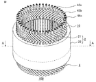
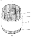
- FIG. 1 is a schematic perspective view of a stator according to Embodiment 1 of the present invention.
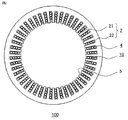
- 2 is a schematic cross-sectional view taken along the line AA of the stator of FIG.
- the stator 100 of the present embodiment includes an annular stator core 2 and a stator coil 10.
- the stator core 2 is formed by a back yoke 22 that is an outer peripheral portion and teeth 21 that protrude in the radial direction from the inner peripheral surface of the back yoke 22, and slots 5 are formed between the teeth 21.
- the stator coil 10 is formed of a plurality of unit coils 4 to be described later, and three phases of a U phase, a V phase, and a W phase are Y-connected.
- the unit coil 4 is inserted into the slot 5 and wound around the teeth 21.
- the unit coil 4 has a portion exposed from the stator core 2 in the axial direction.
- the exposed portion side of the unit coil 4 having the first terminal wire 42a and the second terminal wire 42b is defined as the terminal side, and the opposite side is defined as the non-terminal side.
- the stator core 2 having 48 slots 5 and 48 teeth is illustrated, but the present invention is not limited to this.
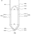
- FIG. 3 is a schematic front view (a) and a schematic perspective view (b) of the unit coil according to Embodiment 1 of the present invention.
- FIG. 4 is a partial schematic view of a cross section perpendicular to the axial direction of the stator core in which one unit coil according to Embodiment 1 of the present invention is disposed.
- the unit coil 4 is formed by winding a single conducting wire 3 composed of a conductor portion and an insulating film covering the surface of the conductor portion into a substantially hexagonal shape. That is, it is formed in concentric winding.
- the unit coil 4 is disposed in the two slots 5 across the plurality of teeth 21. That is, the stator coil 10 of the present embodiment is a distributed winding coil.
- the unit coil 4 includes a slot accommodating portion that is a portion accommodated in each of the two slots 5, a coil end portion that connects the slot accommodating portions, and a terminal wire that extends from each slot accommodating portion.
- the slot storage portion located on the left side of the paper is the first slot storage portion 41a
- the other slot storage portion located on the right side of the paper is the second slot storage portion 41b.
- the first slot storage portion 41 a and the second slot storage portion 41 b are each formed by two conducting wires 3.
- the first slot accommodating portion 41a is configured by a first slot accommodating portion inner conducting wire 41a1 positioned inside and a first slot accommodating portion outer conducting wire 41a2 positioned outside.
- the second slot accommodating portion 41b is configured by a second slot accommodating portion inner conducting wire 41b1 located inside and a second slot accommodating portion outer conducting wire 41b2 located outside.
- the first slot accommodating portion inner conducting wire 41a1 is positioned radially inside the first slot accommodating portion outer conducting wire 41a2, and the second slot accommodating portion inner conducting wire 41b1
- the two-slot housing portion outer conductor 41b2 is located on the inner side in the radial direction.
- the slot 5 in which the first slot storage portion 41 a is disposed and the slot 5 in which the second slot storage portion 41 b is disposed are spaced apart by inserting a predetermined number of teeth in the radial direction. It is arranged.
- the slot 5 in which the second slot accommodating portion 41b of one unit coil 4 is disposed is a timepiece in the circumferential direction with respect to the slot 5 in which the first slot accommodating portion 41a is disposed. A predetermined number of teeth are inserted in the rotation direction and are in a separated position.
- the first slot accommodating portion 41 a is disposed in the slot 5 on the left side in the circumferential direction of the stator core 2 as viewed from the terminal side, and This is a case where the two-slot storage portion 41b is provided.
- the first slot accommodating portion inner conducting wire 41a1 is arranged on the inner side in the radial direction, and the first slot accommodating portion outer conducting wire 41a2 is disposed. Is arranged outside in the radial direction.
- the second slot accommodating portion inner conducting wire 41b1 is disposed on the radially inner side
- the second slot accommodating portion outer conducting wire 41b2 is disposed on the radially outer side.
- the positional relationship of the radial direction of the conducting wire in each slot accommodating part of the unit coil 4 is as follows.
- the position of the second slot housing portion inner conductor 41b1 in the radial direction is shifted by one conductor 3 outward from the position of the first slot housing portion inner conductor 41a1.
- the position of the first slot housing portion outer conductor 41a2 in the radial direction is shifted by one conductor wire 3 outward from the position of the second slot housing portion inner conductor 41b1.
- the position of the second slot housing portion outer conducting wire 41b2 in the radial direction is shifted by one of the conducting wires 3 from the position of the first slot housing portion outer conducting wire 41a2.
- the position of the second slot housing portion outer conductive wire 41b2 in the radial direction is shifted by three conductors 3 outward from the position of the first slot housing portion inner conductive wire 41a1.
- the unit coil 4 includes a first terminal wire 42a extending from the first slot housing portion outer conducting wire 41a2 and a second terminal wire 42b extending from the second slot housing portion outer conducting wire 41b2. And have.
- a coil end portion (referred to as a terminal-side coil end portion) 42c that connects the first slot housing portion inner conducting wire 41a1 and the second slot housing portion inner conducting wire 41b1 to the side where each terminal wire 42a, 42b is located, that is, the terminal side.
- a coil end portion (referred to as a first anti-terminal-side coil end portion) 43a that connects the first slot housing portion outer conductor 41a2 and the second slot housing portion inner conductor 41b1 to the non-terminal side, and a first slot housing A coil end portion (referred to as a second non-terminal side coil end portion) 43b that connects the inner conductor 41a1 and the second slot housing outer conductor 41b2 is provided.
- FIG. 5 is a partial schematic view of the end face on the terminal side of the stator core in which one unit coil according to Embodiment 1 of the present invention is disposed.
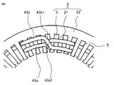
- FIG. 6 is a partial schematic view of the end surface on the opposite end side of the stator core in which one unit coil according to Embodiment 1 of the present invention is disposed.
- the terminal-side coil end portion 42 c adjusts the deviation of the second slot housing portion inner conductor 41 b 1 toward the radially outer side of one conductor wire 3 with respect to the first slot housing portion inner conductor 41 a 1.
- a lane change part 42c1 is provided. In other words, the lane change portion 42c1 changes the width of one conductor 3 in the radial direction.
- the first anti-terminal-side coil end portion 43 a has a first slot housing portion outer conductor 41 a 2 radially outward of one conductor 3 with respect to the second slot housing portion inner conductor 41 b 1.
- a lane change portion 43a1 for adjusting the deviation is provided. In other words, the lane change portion 43a1 changes the width of one conductor 3 in the radial direction.
- the second non-terminal side coil end portion 43b has a lane that adjusts a deviation of the second slot housing portion outer conducting wire 41b2 to the radially outer side of three conducting wires 3 with respect to the first slot housing portion inner conducting wire 41a1.
- a change portion 43b1 is provided.
- the lane change portion 43b1 changes the width of three conductor wires 3 in the radial direction.
- the second anti-terminal-side coil end portion 43b is disposed on the outer side in the axial direction from the first anti-terminal-side coil end portion 43a, and intersects the first anti-terminal-side coil end portion 43a.
- the second terminal wire 42b extends from the second slot housing portion outer conductor 41b2 located at the radially outermost position, and the first terminal wire 42a is one of the conductors 3 from the radially outermost side. It extends from the first slot housing portion outer conductor 41a2 located at the inner position.
- the first terminal wire 42a extends from the first slot housing portion outer conducting wire 41a2, the second terminal wire 42b extends from the second slot housing portion outer conducting wire 41b2, and the terminal side coil end
- the portion 42c connects the first slot housing portion inner conductor 41a1 and the second slot housing portion inner conductor 41b1.
- the first terminal wire 42a extends from the first slot housing portion inner conductor 41a1
- the second terminal wire 42b extends from the second slot housing portion inner conductor 41b1
- the terminal side coil end portion 42c The 1-slot housing portion outer conductive wire 41a2 and the second slot housing portion outer conductive wire 41b2 may be connected.
- the unit coil 4 has the first slot housing part 41a and the second slot housing part 41b formed by two conductors 3, respectively, but the conductors forming each slot housing part are:
- Each of the number n may be equal to or less than a range in which a stator coil can be formed.
- n is an integer of 2 or more.
- the unit coil includes (n-1) terminal-side coil end portions, (n-1) first anti-terminal-side coil end portions, and one second anti-terminal-side coil end portion. It has.
- Each terminal-side coil end portion and each first anti-terminal-side coil end portion are provided with lane change portions that dodge the width of one conductor. That is, each terminal-side coil end portion and each first anti-terminal-side coil end portion connect the first slot housing portion conducting wire and the second slot housing portion conducting wire that are shifted by one conducting wire in the radial direction.
- a lane change portion that avoids the width of (2n-1) conductors is provided at the second end side coil end portion. That is, the second non-terminal side coil end portion connects the first slot housing portion conducting wire and the second slot housing portion conducting wire which are shifted by (2n ⁇ 1) conductor wires in the radial direction.
- the second anti-terminal side coil end portions are arranged on the outer side in the axial direction than the first anti-terminal side coil end portions, and (n ⁇ 1) first anti-terminal side coil end portions 43a and Crossed.
- the second terminal wire extends from the second slot housing portion conducting wire located at the radially outermost position, and the first terminal wire extends from the second slot housing portion conducting wire located at the radially outermost position. It extends from the first slot housing portion conducting wire at a position inside the conducting wire 3 in the direction. However, the first terminal wire extends from the first slot housing portion conducting wire located at the radially innermost position, and the second terminal wire extends from the first slot housing portion conducting wire located at the radially innermost position. You may extend from the 2nd slot accommodating part conducting wire which exists in the position of one conducting wire 3 outside in the direction. Both conducting wires extending from the terminal wire are not connected at the terminal-side coil end portion. Moreover, the 1st terminal wire and the 2nd terminal wire have shifted
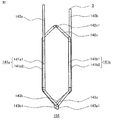
- FIG. 7 is a schematic front view of a conventional unit coil.
- the conventional unit coil 104 is also formed by wrapping one conductive wire, and connects the first slot accommodating portion 141a, the second slot accommodating portion 141b, and the slot accommodating portions. A coil end portion and a terminal wire extending from each slot storage portion are provided.
- the first slot accommodating portion 141a is formed of two conductors, a first slot accommodating portion inner conductor 141a1 on the front side in FIG. 7 and a first slot accommodating portion outer conductor 141a2 on the rear side in FIG.
- the second slot accommodating portion 141b is formed of two conductors, a second slot accommodating portion inner conductor 141b1 on the front side in FIG. 7 and a second slot accommodating portion outer conductor 141b2 on the rear side in FIG.
- the coil end portion includes a first anti-terminal side coil end portion 143a that connects the first slot housing portion inner conductor 141a1 and the second slot housing portion inner conductor 141b1, and a second slot housing portion inner conductor 141b1 and the first slot housing.
- the terminal side coil end portion 142c is provided with a lane change portion 142c1 for evacuating the width of one conductor 3 in the radial direction.
- the first counter terminal side coil end portion 143a is provided with a lane change portion 143a1 for changing the width of one conductor 3 in the radial direction.
- the second counter terminal side coil end portion 143b is provided with a lane change portion 143b1 for changing the width of one conductor 3 in the radial direction.
- the terminal wire includes a first terminal wire 142a extending from the first slot housing portion inner conducting wire 141a1 and a second terminal wire 142b extending from the second slot housing portion outer conducting wire 141b2. That is, in the radial direction, the position of the first terminal wire 142 a and the position of the second terminal wire 142 b are shifted by three conductor wires 3.
- FIG. 8 is a schematic perspective view of a stator intermediate body in which a unit coil of a comparative example is mounted on a stator core.
- FIG. 9 is a partial end face schematic diagram of the stator intermediate body of FIG.
- each terminal wire is not joined to the terminal wire of another unit coil.
- the first terminal wire 142a of one unit coil 104 is joined to the second terminal wire 142b of the unit coil 104 that is not inserted, for example, 5 slots in the counterclockwise circumferential direction.
- the second terminal wire 142b is joined in the clockwise circumferential direction to the first terminal wire 142a of the unit coil 104, for example, in which 5 slots are not inserted.
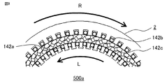
- the stator intermediate body 500a shown in FIGS. 8 and 9 has a first terminal wire 142a of the unit coil 104 and a second terminal wire 142b of another unit coil 104 joined to the first terminal wire 142a. It is not arranged at a position facing in the direction. Therefore, in order to join the first terminal wire 142a of the unit coil 104 and the second terminal wire 142b of the other unit coil 104, first, the first terminal wire 142a of the unit coil 104 is indicated by an arrow L in FIG. Bend counterclockwise. At this time, the bent first terminal line 142 a is formed in an arc shape that is substantially parallel to the inner peripheral surface of the stator core 2.
- the inner peripheral surface of the stator core 2 is a surface that faces the outer peripheral surface of a rotor that is installed when a rotating electrical machine is used.
- the second terminal wire 142b of the unit coil 104 is bent in the clockwise direction indicated by the arrow R in FIG.
- the bent second terminal line 142b is formed in an arc shape that is substantially parallel to the inner peripheral surface of the stator core 2. The bending of the first terminal wire 142a and the bending of the second terminal wire 142b are performed simultaneously for all the unit coils 104.
- FIG. 10 is a schematic perspective view showing a stator intermediate body in which the first terminal wire and the second terminal wire to be joined are opposed to each other in the radial direction in the unit coil of the comparative example.
- FIG. 11 is a partial end face schematic diagram of the stator intermediate body of FIG. 10 as seen from the direction indicated by the arrow F.
- the stator intermediate body 500b shown in FIGS. 10 and 11 is disposed at a position where the first terminal wire 142a of the unit coil 104 and the second terminal wire 142b of the other unit coil 104 face each other in the radial direction. .
- the first terminal wires 142a and the second terminal wires 142b of the other unit coils 104 are arranged away from each other in the radial direction.
- FIG. 12 is a partial perspective schematic view showing a stator intermediate body in which the first terminal wire in the unit coil of the comparative example is brought close to the second terminal wire.
- 13 is a partial schematic end view of the stator intermediate body of FIG.
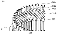
- FIG. 14 is a partial perspective schematic view showing a stator of a comparative example.
- the gathering portion 144a is joined by welding, 14 is obtained as a comparative example.
- the welded portion 144c is the top of the first terminal line 142a and the second terminal line 142b.
- the welded portion 144c is not limited to this as long as it is a portion of the gathering portion 144a.
- at least one terminal line of the first terminal line 142a and the second terminal line 142b straddles the terminal side coil end portion. In other words, the stator coil has a straddling portion 144b.
- FIG. 15 is a schematic diagram illustrating a state before the unit coil according to the first embodiment of the present invention is attached to the stator core.
- the first terminal wire 42a extending without being bent from the first slot housing portion outer conducting wire 41a2 and the second slot housing portion outer conducting wire 41b2 without being bent, as shown in FIG.
- the unit coil 4 including the second terminal wire 42b is attached to the stator core 2.
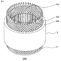
- FIG. 16 is a schematic perspective view of a stator intermediate body to which a unit coil having unfolded terminal wires is attached according to the first embodiment of the present invention.
- FIG. 17 is a partial schematic end view of the stator intermediate shown in FIG. 16 as viewed from the direction indicated by arrow F.
- a plurality of unit coils 4 are attached to the stator core 2.
- the conductors of the slot accommodating portions of the other unit coils 4 are inserted between the conductors of the slot accommodating portions of the unit coils 4.
- 16 and 17 show a state in which each terminal wire is not joined to the terminal wire of another unit coil.
- the first terminal wire 42a of one unit coil 4 is in the counterclockwise circumferential direction, for example, the second terminal wire 42b of another unit coil 4 that is not inserted into 5 slots.
- the second terminal wire 42b is joined to the first terminal wire 42a of another unit coil 4 that is not inserted in, for example, five slots in the clockwise circumferential direction.
- the stator intermediate body 100a to which the unit coil 4 is mounted is opposed to the second terminal wire 42b of the other unit coil 4 joined to the first terminal wire 42a of the unit coil 4 in the radial direction. Not placed in position. Therefore, in order to join the first terminal wire 42a of the unit coil 4 and the second terminal wire 42b of the other unit coil 4, first, the first terminal wire 42a of the unit coil 4 is indicated by the arrow L shown in FIG. Bend in the counterclockwise direction shown. At this time, the bent first terminal line 42 a has an arc shape that is substantially parallel to the inner peripheral surface of the stator core 2.
- the second terminal wire 42b of the unit coil 4 is bent in the clockwise direction indicated by the arrow R shown in FIG.
- the bent second terminal line 42 b has an arc shape that is substantially parallel to the inner peripheral surface of the stator core 2. The bending of the first terminal wire 42a and the bending of the second terminal wire 42b are performed simultaneously for all the unit coils 4.
- FIG. 18 is a schematic perspective view illustrating a stator intermediate body in which the first terminal wire and the second terminal wire to be joined are opposed to each other in the radial direction in the unit coil according to Embodiment 1 of the present invention.
- FIG. 19 is a partial end face schematic diagram of the stator intermediate shown in FIG.
- the stator intermediate body 100b shown in FIGS. 18 and 19 is arranged at a position where the first terminal wire 42a of the unit coil 4 and the second terminal wire 42b of the other unit coil 4 joined to each other are opposed in the radial direction. ing. And the 2nd terminal wire 42b of the other unit coil 4 joined to the 1st terminal wire 42a is contacting in radial direction.
- the first terminal wire 42a and the second terminal wire 42b of the other unit coil 4 that are opposed to and in contact with each other are joined by welding to fix the present embodiment.
- a contact portion 44a Get a child 100.
- the welded portion 44 c is at the top of the first terminal line 42 a and the second terminal line 42 b, but the first terminal line 42 a and the second terminal line 42 b If it is the contact part 44a with the terminal line 42b, it will not be limited to this.
- stator 100 of the present embodiment it is not necessary to bend at least one terminal wire of the first terminal wire 42a and the second terminal wire 42b in the radial direction so that the terminal wires are brought together.
- the number of bendings 3 is small, the number of stator manufacturing steps can be reduced, and the productivity is improved.
- count of bending of the conducting wire 3 is few, the frequency which the insulating film of the conducting wire 3 is damaged can be reduced, the damage of a coil becomes small, and the insulation reliability of a stator is excellent.
- FIG. 20 is a partial schematic diagram illustrating a cross section orthogonal to the circumferential direction of the stator of the comparative example.
- FIG. 21 is a partial schematic diagram illustrating a cross section orthogonal to the circumferential direction of the stator according to the first embodiment of the present invention. 20 and 21 both show the terminal side of the stator. As shown in FIG. 20, in the stator 500 of the comparative example, the first terminal wire 142a is bent and brought together with the second terminal wire 142b, and a straddling portion 144b is formed. That is, since there is the straddling portion 144b, a cover that protects the terminal-side coil end portion 142c during welding cannot be provided.
- the terminal side coil end portion 42c can be welded with the cover 8 covered, and the terminal side coil end portion 42c is sputtered. Can be prevented. That is, it is possible to prevent deterioration of the insulation quality of the coil due to sputtering during welding, and the reliability is excellent.
- the stator according to the present embodiment has no straddle portion, the coil end height corresponding to the straddle portion can be reduced.
- a round wire is used as the conducting wire, but it is not limited to a round wire, and may be a flat wire.
- the slot 5 in which the second slot storage portion 41b is disposed has a predetermined number of teeth in the clockwise direction in the circumferential direction with respect to the slot 5 in which the first slot storage portion 41a is disposed. It is in a position away from the insertion.
- the slot 5 in which the second slot accommodating portion 41b is disposed is separated from the slot 5 in which the first slot accommodating portion 41a is disposed by inserting a predetermined number of teeth counterclockwise in the circumferential direction. It may be a different position.
- the first slot accommodating portion 41a is accommodated in the slot 5 located on one side which is spaced by inserting a predetermined number of teeth in the circumferential direction, and the slot 5 located on the other side
- the second slot storage portion 41b is stored.
- FIG. 22 is a schematic perspective view showing a stator intermediate body in which a stator core is mounted on a coil cage in the stator according to the second embodiment of the present invention.
- the stator intermediate body 200a in which the stator core 202 is mounted on the coil rod 206 shown in FIG. 22 the first terminal wire 42a and the second terminal wire 42b are not yet bent in the circumferential direction and are welded. It is not joined by etc.
- the stator core 202 is formed by connecting the stator core structural bodies 202a in the circumferential direction and arranging them in an annular shape.
- each tooth 221 is circumferentially directed from the circumferential end face (referred to as the back yoke forming part circumferential end face) 222b of the back yoke forming part 222a.
- Each stator core structure 202a is brought into contact with and joined at the circumferential end surface 222b of the back yoke forming portion, and the stator core 202 formed in an annular shape is formed by teeth of the adjacent stator core structure 202a.
- a slot 205 is also formed between the opposing teeth circumferential outer end surfaces 221b of 221.
- FIG. 24 is a schematic perspective view of a coil cage used in the stator according to Embodiment 2 of the present invention.
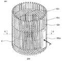
- the coil cage 206 of the present embodiment is formed by arranging a plurality of unit coils 4 in the circumferential direction.
- the coil rod 206 will be described in detail later, and a plurality of unit coils 4 are mounted by inserting a conductor of a slot accommodating portion of the other adjacent unit coil 4 between the conductors of the slot accommodating portion of one unit coil 4. It is formed in an annular arrangement.
- FIG. 25 is a schematic front view showing two unit coils used for manufacturing a coil cage according to Embodiment 2 of the present invention.
- a unit coil (referred to as an insertion-side unit coil) 45a into which the conductor of the slot housing portion is inserted is shown on the left side of the drawing when the coil cage 206 is manufactured, and the conductor wire is inserted between the conductors of the slot housing portion.
- An inserted unit coil (referred to as a receiving-side unit coil) 45b is shown on the right side of the drawing.
- FIG. 26 is a schematic diagram of the terminal-side upper surface for explaining a state in which the insertion-side unit coil is disposed so as to overlap the receiving-side unit coil when the coil cage according to the second embodiment of the present invention is manufactured.
- the second slot accommodating portion inner conductor 41b1 of the insertion side unit coil 45a is moved while rotating in the direction indicated by the arrow S, and the first slot accommodating portion inner conductor of the receiving side unit coil 45b is moved.
- 41a1 and the 1st slot accommodating part outer side conducting wire 41a2 are passed and arrange
- the second slot housing portion outer conducting wire 41b2 of the insertion side unit coil 45a is moved while rotating in the direction indicated by the arrow S, and the outer side in the radial direction of the first slot housing portion outer conducting wire 41a2 of the receiving side unit coil 45b. Is placed across. That is, the insertion-side unit coil 45a and the receiving-side unit coil 45b are stacked while being shifted in the circumferential direction.
- FIG. 27 is a front schematic diagram (a) and a terminal-side top schematic diagram illustrating a state in which the insertion-side unit coil is disposed in the receiving-side unit coil when the coil cage according to the second embodiment of the present invention is manufactured.
- the overlapping insertion-side unit coil 45a and receiving-side unit coil 45b are configured such that the first slot accommodating portion 41a of the inserting-side unit coil 45a is the first slot accommodating portion 41a of the receiving-side unit coil 45b.
- the slot 205 is shifted by one in the counterclockwise circumferential direction, and the second slot storage portion 41b of the insertion-side unit coil 45a is offset from the second slot storage portion 41b of the reception-side unit coil 45b.
- the slot 205 is shifted by one in the counterclockwise circumferential direction.
- the coil cage 206 is formed by arranging the unit coils in an annular shape while shifting the unit coils.
- the shift amount for one slot is the angle formed by two sides connecting the center and a similar position of the unit coil overlapping the unit coil. It is in a state of 7.5 degrees.
- the shift amount for one slot is also different, and is not limited to 7.5 degrees.
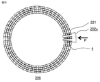
- FIG. 28 is a schematic perspective view illustrating a state where the stator core structure is assembled to the coil rod according to the second embodiment of the present invention.
- 29 is a schematic cross-sectional view taken along the line BB of the coil cage of FIG.
- the assembly of the stator core structure 202a to the coil cage 206 is performed first between the slot accommodating portions of the plurality of unit coils 4 forming the coil cage 206.
- the teeth 221 of the structure 202a are inserted.
- the teeth 221 are inserted into the coil cage 206 by pushing the stator core structure 202a in the direction indicated by the arrow P from the outer peripheral side of the coil cage 206 and moving it inward in the radial direction.
- stator core components 202a are attached to the coil cage 206, and the stator intermediate body 200a shown in FIG. 22 is produced.
- stator intermediate 200a all the slot storage portions are stored in the slots 205.
- Each stator core component 202a attached to the coil cage 206 and arranged in an annular shape in contact with the circumferential end surface 222b of the back yoke forming portion joins and integrates the back yoke forming portions 222a by welding or the like. .
- the integrated back yoke forming portion 222a becomes the back yoke of the stator core 202, and the stator core 202 is formed.
- the first terminal wire 42a and the second terminal wire 42b of the unit coil 4 are bent. Then, the first terminal wire 42a of the unit coil 4 and the second terminal wire 42b of the other unit coil 4 are opposed to each other in the radial direction and are in contact with each other. Next, the first terminal wire 42a and the second terminal wire 42b of the other unit coil 4 that are opposed to and in contact with each other are joined by welding or the like to complete the stator coil, whereby the stator is manufactured.
- the first terminal wire 42a and the second terminal wire 42b of the unit coil 4 are arranged in a state in which one conductor wire is shifted in the radial direction.
- the one terminal wire 42a and the second terminal wire 42b of the other unit coil 4 can be opposed to each other in the radial direction without providing a straddling portion, and can be brought into contact with each other, and are similar to the stator of the first embodiment. Has an effect.
- the stator core assembly 202a is inserted into the coil cage 206 from the outer peripheral direction in the radial direction, the stator is manufactured. Therefore, the stator core can be easily attached to the stator coil, and productivity is improved.
- stator core structure 202a since the load applied to the stator coil is small when the stator core structure 202a is inserted into the coil cage 206, it is possible to prevent the insulation of the unit coil 4 from being lowered.
- two teeth are provided in the stator core structure, but the number of teeth is not limited to two.
- FIG. 3 The stator according to the third embodiment of the present invention includes a stator coil and a stator core on which the stator coil is mounted.
- the unit coil used in the present embodiment has the same shape as that of the unit coil 4 of the first embodiment, and is formed by winding one conductive wire.
- the coil cage forming the stator coil is the same as the coil cage 206 of the second embodiment.
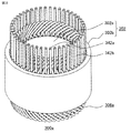
- FIG. 30 is a schematic perspective view showing a stator intermediate body in which a contraction coil rod is mounted on the stator core in the stator according to Embodiment 3 of the present invention.
- stator intermediate body 300a shown in FIG. 30 in which the contraction coil rod 306a is mounted on the stator core 302 the first terminal wire 342a and the second terminal wire 342b are not yet bent in the circumferential direction, and Not joined by welding or the like.
- the stator core 302 shown in FIG. 30 is formed of an inner core 302a that is radially inward and an outer core 302b that is separate from the inner core 302a and that is radially outward.
- the outer core 302b is a back yoke of the stator core 302.
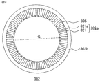
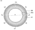
- FIG. 31 is a schematic diagram of an axial end surface of a stator core used in the stator according to Embodiment 3 of the present invention.
- the inner core 302a is formed of a plurality of teeth 321 and a plurality of connecting portions 321a.
- the plurality of teeth 321 are arranged radially with a constant interval in the circumferential direction.
- the connecting portion 321a connects the radially inner tip portions of adjacent teeth 321 together.
- annular body is formed with the front-end
- a slot 305 is formed between adjacent teeth 321.
- the outer core 302b serving as the back yoke of the stator core 302 has a cylindrical shape. The inner peripheral surface of the outer core 302b fixes the radially outer end of the teeth 321 of the inner core 302a.
- FIG. 32 is a schematic diagram of the end face in the axial direction, showing a state in which the inner core is arranged in the coil cage according to the third embodiment of the present invention.
- the coil cage 306 is manufactured by the same operation as that in the second embodiment.
- the circumferential width of the coil end portion on the terminal side and the circumferential end width of the coil end portion on the opposite end side of the unit coil to be used are large, and the inner diameter of the coil rod 306 is that of the inner core 302a. It is larger than the outer diameter D.
- the inner core 302 a is installed on the inner peripheral side of the coil rod 306.
- FIG. 32 is a schematic diagram of an end face in the axial direction showing a state in which the contraction coil rod is attached to the inner core according to the third embodiment of the present invention.
- the contraction coil rod 306a attached to the inner core 302a all slot accommodating portions are accommodated in the slots 305.
- the inner core 302a to which the contraction coil rod 306a is attached is press-fitted into the outer core 302b to produce a stator intermediate body 300a shown in FIG.
- the first terminal wire 342a and the second terminal wire 342b of the contraction unit coil are bent.
- the second terminal wire 342b of the other contraction unit coil joined to the first terminal wire 342a of the contraction unit coil is opposed to and in contact with the radial direction.
- the first terminal wire 342a facing and in contact with the second terminal wire 342b of another contraction unit coil is joined by welding or the like to complete the stator coil, whereby the stator is manufactured. .
- the first terminal wire 342a and the second terminal wire 342b of the installed unit coil are arranged in a state of being shifted by one conductor wire in the radial direction.
- the first terminal wire 342a of the coil and the second terminal wire 342b of the other unit coil installed can be opposed to each other in the radial direction without providing a straddling portion, and can be brought into contact with each other. It has the same effect as a stator.
- the stator core 302 used in the stator of the present embodiment is connected to the radially inner tip of the teeth 321 by the connecting portion 321a, the shape accuracy of the inner periphery of the stator core is excellent. ing. Therefore, the rotating electrical machine using the stator of the present embodiment has less cogging torque and torque ripple.
- the stator according to the fourth embodiment of the present invention also includes a stator coil and a stator core on which the stator coil is mounted.
- the stator core used in the present embodiment is the same as the stator core 302 of the third embodiment.
- the shape of the unit coil and the shape of the coil cage are different from those of the third embodiment.
- the number of conductive wires in the slot housing portion, the number of each coil end portion, and the width dominated by the lane change portion are the same as in the third embodiment.
- the unit coil is formed by winding one conductive wire.
- FIG. 34 is a schematic front view of a unit coil according to Embodiment 4 of the present invention.
- the circumferential width of the terminal side coil end portion 442c (referred to as the width of the terminal side coil end portion) E1 is the first counter terminal side coil end portion.
- the width in the circumferential direction of 443a and the second anti-terminal-side coil end portion 443b (referred to as the width of the anti-terminal-side coil end portion) is wider than E2.
- a lane change portion 442c1 is provided in the terminal side coil end portion 442c
- a lane change portion 443a1 is provided in the first counter terminal side coil end portion 443a
- the second A lane change portion 443b1 is provided on the non-terminal side coil end portion 443b.
- the first slot storage portion 441a includes a first slot storage portion inner conductor 441a1 and a first slot storage portion outer conductor 441a2.
- the second slot storage portion 441b is composed of a second slot storage portion inner conductor 441b1 and a second slot storage portion outer conductor 441b2.
- FIG. 35 is a schematic side view of one unit coil forming a coil cage according to Embodiment 4 of the present invention.
- the unit coil 404 has an arrow extending from the first and second slot accommodating portions 441a and 441b, and the first and second terminal wires 442a and 442b and the terminal-side coil end portion 442c are It is bent inward in the radial direction of the coil rod indicated by M.
- the first and second opposite terminal side coil end portions 443a and 443b are bent outward in the radial direction of the coil rod indicated by the arrow N with respect to the extension line of the first and second slot accommodating portions 441a and 441b. Yes.
- the coil rod 406 of the present embodiment is manufactured by the same method as the coil rod 206 of the second embodiment. That is, the unit coils 404 are shifted in the circumferential direction by passing the lead wire of the second slot storage portion 441b in the unit coil 404 on the insertion side between the lead wires of the first slot storage portion 441a in the unit coil 404 on the receiving side. And overlap. Then, all the unit coils 404 are shifted in the circumferential direction and overlapped to be arranged in an annular shape, whereby the coil rod 406 is manufactured.
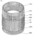
- FIG. 36 is a schematic perspective view of a coil cage used in the stator according to Embodiment 4 of the present invention.
- the inner diameter on the terminal side is larger than the inner diameter on the opposite terminal side.
- the inner diameter of the coil rod 406 on the terminal side is larger than the outer diameter D of the inner core 302a shown in FIG.
- the inner diameter of the coil rod 406 on the side opposite to the terminal is larger than the diameter G between the bottoms of the opposing slots 305 in the inner core 302a shown in FIG.
- the difference between the inner diameter on the terminal side of the coil rod 406 and the outer diameter D of the inner core 302a and the difference between the inner diameter on the opposite side of the coil rod 406 and the inter-slot diameter G are preferably small.
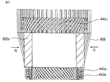
- FIG. 37 is a schematic cross-sectional view showing a state in which the inner core is disposed on the coil cage according to the fourth embodiment of the present invention.
- FIG. 38 is a schematic perspective view showing the inner core on which the contracting coil cage according to the fourth embodiment of the present invention is mounted.
- FIG. 39 is a schematic diagram showing a cross section perpendicular to the radial direction of the inner core to which the contraction coil cage of FIG. 38 is attached.
- the coil rod 406 is attached to the inner core 302a by first inserting the inner core 302a from the terminal side of the coil rod 406. Then, as shown in FIG. 37, force is applied to the coil rod 406 from the outer peripheral side indicated by the arrow Q. At this time, the teeth 321 of the inner core 302 a are inserted into the gaps between the slot housing portions of the coil rod 406, and the coil rod 406 contracts to accommodate all the slot housing portions in the slot 305. Then, as shown in FIGS. 38 and 39, the contraction coil rod 406a is attached to the inner core 302a.
- FIG. 40 is a schematic front view showing a contraction unit coil that forms a contraction coil cage according to the fourth embodiment of the present invention.
- the circumferential width of the terminal-side coil end portion 442c is reduced in the process in which the coil rod 406 is attached to the inner core 302a.
- the unit coil 404 is a contraction unit coil 404a in which the circumferential width of the terminal-side coil end portion 442c is substantially the same as the circumferential width E2 of the non-terminal-side coil end portion. .
- FIG. 41 is a schematic perspective view showing a stator intermediate body according to the fourth embodiment of the present invention.
- the first terminal wire 442a and the second terminal wire 442b of the contraction unit coil 404a are bent.
- the second terminal wire 442b of the other contraction unit coil 404a joined to the first terminal wire 442a of the contraction unit coil 404a is opposed to and brought into contact with the radial direction.
- the first terminal wire 442a and the second terminal wire 442b of the other contraction unit coil 404a that are opposed to and in contact with each other are joined by welding or the like to complete the stator coil, whereby the stator is manufactured.
- first terminal wire 442a and the second terminal wire 442b of the unit coil installed in the stator of the present embodiment are also arranged in a state shifted by one conductor in the radial direction, the installed unit coil
- the first terminal wire 442a of the coil and the second terminal wire 442b of the other installed unit coil can be opposed to each other in the radial direction without providing a straddling portion, and can be brought into contact with each other. It has the same effect as a stator.
- stator core is the same as that of the third embodiment, the shape accuracy of the inner periphery of the stator core is excellent, and the rotating electrical machine using the stator of the present embodiment also has cogging torque and torque. Ripple is reduced. Further, in the stator according to the present embodiment, the terminal side coil end portion of the unit coil 404 is deformed at the time of production, but the counter terminal side coil end portion is not deformed. Reliability is excellent.
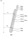
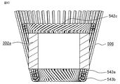
- FIG. 42 is a schematic side view of one unit coil forming the coil cage according to the fifth embodiment of the present invention.
- FIG. 43 is a schematic cross-sectional view showing a state in which the inner core is disposed on the coil rod used in the stator according to Embodiment 5 of the present invention.
- the inner core 302a in FIG. 43 is inserted into the coil cage 506 from the terminal side.
- the unit coil 504 used in the coil rod 506 shown in FIG. 42 includes first and second terminal wires 542a and 542b, a terminal-side coil end portion 542c, and first and second non-terminal-side coil end portions 543a.
- 543b is the same as the unit coil 404 except that it is not bent in the radial direction of the coil rod with respect to the extended line of the first and second slot accommodating portions 541a, 541b.
- the first slot storage portion 541a is composed of a first slot storage portion inner conductor 541a1 and a first slot storage portion outer conductor 541a2.
- the second slot storage portion 541b is composed of a second slot storage portion inner conductor 541b1 and a second slot storage portion outer conductor 541b2.
- a step of forming a contraction coil cage and attaching it to the inner core 302a, and press fitting the inner core 302a fitted with the contraction coil cage into the outer core 302b The step of producing and the step of joining the second terminal wire 542b of the other contraction unit coil joined to the first terminal wire 542a are the same as the manufacture of the stator of the fourth embodiment. Therefore, the stator using the coil cage 506 of the present embodiment has the same effect as the stator using the coil cage 406.
- first and second terminal wires 542a and 542b and the terminal-side coil end portion 542c and the first and second non-terminal-side coil end portions 543a and 543b are not bent in the radial direction of the coil rod, the unit The number of portions where the coil is bent is reduced, the number of manufacturing steps of the unit coil can be reduced, and productivity is further improved. Moreover, since the frequency with which the insulating film of the conducting wire 3 is damaged can be further reduced, the damage to the coil is reduced, and the insulation reliability of the stator is further improved.
- the stator according to Embodiment 6 of the present invention also includes a stator coil and a stator core on which the stator coil is mounted.
- the stator core used in the present embodiment is the same as the stator core 302 of the third embodiment.
- the shape of the unit coil and the shape of the coil cage are different from those of the fourth embodiment.
- the number of conducting wires in the slot housing portion, the number of each coil end portion, and the width dominated by the lane change portion are the same as in the fourth embodiment.
- the unit coil is formed by winding one conductive wire.
- FIG. 44 is a schematic front view of a unit coil according to Embodiment 6 of the present invention.
- the unit coil 604 of the present embodiment has a circumferential width of the first anti-terminal side coil end portion 643a and the second anti-terminal side coil end portion 643b (the width of the anti-terminal side coil end portion).
- E4 is wider than the circumferential width of the terminal-side coil end portion 642c (denoted as the width of the terminal-side coil end portion) E3.
- a lane change portion 642c1 is provided in the terminal side coil end portion 642c
- a lane change portion 643a1 is provided in the first counter terminal side coil end portion 643a
- the second A lane change portion 643b1 is provided on the non-terminal side coil end portion 643b.
- the first slot accommodating portion 641a is composed of a first slot accommodating portion inner conductor 641a1 and a first slot accommodating portion outer conductor 641a2.
- the second slot accommodating portion 641b is composed of a second slot accommodating portion inner conductor 641b1 and a second slot accommodating portion outer conductor 641b2.
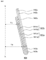
- FIG. 45 is a schematic side view of one unit coil forming a coil cage according to Embodiment 6 of the present invention.
- a unit coil 604 used in a coil rod 606, which will be described later has first and second terminal wires 642a and 642b with respect to an extension line of the first and second slot accommodating portions 641a and 641b.
- the terminal side coil end part 642c and the first and second counter terminal side coil end parts 643a and 643b are not bent in the radial direction of the coil rod 606.
- the unit coil 604 forming the coil rod 606 has a distance T4 between the central axis X of the coil rod 606 and the end of the slot accommodating portion on the opposite end side, and the center axis X of the coil rod 606 and the slot accommodating portion. It is larger than the distance T3 from the terminal side end. That is, the slot accommodating portions 641a and 641b of the unit coil 604 forming the coil rod 606 are inclined.
- the coil rod 606 of the present embodiment is manufactured by the same method as the coil rod 206 of the second embodiment. That is, the unit coils 604 are shifted in the circumferential direction by passing the conductors of the second slot housing part 641b in the insertion-side unit coil 604 between the conductors of the first slot housing part 641a in the receiving-side unit coil 604. And overlap. Then, all the unit coils 604 are shifted in the circumferential direction and overlapped and arranged in an annular shape, whereby the coil rod 606 is manufactured.
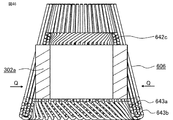
- FIG. 46 is a schematic cross-sectional view showing a state in which the inner core is inserted into the coil cage used in the stator according to Embodiment 6 of the present invention.
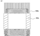
- FIG. 47 is a schematic cross-sectional view showing the inner peripheral core equipped with the contraction coil rod according to the sixth embodiment of the present invention.
- the inner diameter on the non-terminal side is larger than the inner diameter on the terminal side.
- the inner diameter of the coil rod 606 on the opposite end side is larger than the outer diameter D of the inner core 302a shown in FIG.
- the inner diameter on the terminal side of the coil cage 606 is larger than the diameter G between the slots of the inner core 302 shown in FIG. It is preferable that the difference between the inner diameter on the opposite side of the coil rod 606 and the outer diameter D of the inner core 302a and the difference between the inner diameter on the terminal side of the coil rod 606 and the inter-slot diameter G are small.
- the inner core 302a is inserted from the opposite end side of the coil rod 606, and the inner core 302a is inserted into the coil rod 606 shown in FIG.
- a force is applied to the coil rod 606 from the outer peripheral side indicated by the arrow Q.
- the teeth 321 of the inner core 302 a are inserted into the gap between the slot housing portions of the coil rod 606, and the coil rod 606 contracts to accommodate all the slot housing portions in the slot 305.
- the contraction coil rod 606a is attached to the inner core 302a.
- FIG. 48 is a schematic front view showing a contraction unit coil forming a contraction coil cage according to Embodiment 6 of the present invention.
- the width in the circumferential direction of the first and second non-terminal-side coil end portions 643a and 643b is narrowed in the process in which the coil rod 606 is attached to the inner core 302a.
- the contraction unit coil 604a shown in FIG. 48 has the same circumferential width as the terminal-side coil end portion and the circumferential width E3 of the terminal-side coil end portion.
- the inner core 302a to which the contraction coil cage 606a is attached is press-fitted into the outer core 302b (not shown) to produce a stator intermediate body (not shown).
- the first terminal wire 642a and the second terminal wire 642b of the contraction unit coil 604a are bent.
- the second terminal wire 642b of the other contraction unit coil 604a joined to the first terminal wire 642a of the contraction unit coil 604a is opposed to and brought into contact with the second terminal wire 642b of the contraction unit coil 604a.
- the first terminal wire 642a and the second terminal wire 642b of the other contraction unit coil 604a that are opposed to and in contact with each other are joined by welding or the like to complete the stator coil, whereby the stator is manufactured.
- the first terminal wire 642a and the second terminal wire 642b of the installed unit coil are also arranged in a state of being shifted by one conductor wire in the radial direction.
- the first terminal wire 642a of the coil and the second terminal wire 642b of the other unit coil installed can be opposed to each other in the radial direction without providing a straddle, and can be brought into contact with each other. It has the same effect as a stator.
- stator core is the same as that of the third embodiment, the shape accuracy of the inner periphery of the stator core is excellent, and the rotating electrical machine using the stator of the present embodiment also has cogging torque and torque. Ripple is reduced. Further, in the stator according to the present embodiment, the non-terminal side coil end portion of the unit coil 604 is deformed at the time of manufacture, but the terminal side coil end portion is not deformed. Reliability is excellent.
- the first and second terminal wires 642a and 642b and the terminal-side coil end portion 642c have a diameter of the coil rod with respect to the extension wires of the first and second slot housing portions 641a and 641b.
- the first and second non-terminal side coil end portions 643a and 643b are bent inward in the radial direction of the coil rod with respect to the extension lines of the first and second slot accommodating portions 641a and 641b. May be.
- FIG. 49 is a schematic side sectional view of the rotating electrical machine according to the seventh embodiment of the present invention.
- the rotating electrical machine 700 of the present embodiment includes the stator 100 of the first embodiment, the rotor 61 disposed with a predetermined gap on the inner peripheral side of the stator 100, A center of the rotor 61 is inserted in the axial direction, and a rotating shaft 62 for fixing the rotor 61 is provided.
- the rotating shaft 62 is rotatably held by a bearing 63 provided in the housing 60.
- the stator used in rotating electric machine 700 of the present embodiment may be any one of the stators of Embodiments 2 to 6. In the rotating electrical machine 700 of the present embodiment, since the stator is the stator of any one of Embodiments 1 to 6, the insulation reliability and productivity are excellent.
- the manufacturing method of the rotating electrical machine of the present embodiment includes a step of manufacturing the stator 100 by the method described in the first embodiment, a space portion on the inner peripheral side of the manufactured stator 100, a rotating shaft 62, For example, there is a step of inserting the rotor 61 fixed by shrink fitting or the like from the axial direction.
- the stator is manufactured by the method described in the first embodiment, but the stator is manufactured by the method described in any of the second to sixth embodiments. May be produced.
- the stator is manufactured by the method described in any of Embodiments 1 to 6, and thus a rotating electrical machine excellent in insulation reliability and productivity is obtained. Can do.
- stator of the present invention and the rotating electrical machine using this stator are excellent in insulation reliability and productivity, they can be used in industrial equipment that requires low cost and high reliability.
Landscapes
- Engineering & Computer Science (AREA)
- Power Engineering (AREA)
- Manufacturing & Machinery (AREA)
- Manufacture Of Motors, Generators (AREA)
- Windings For Motors And Generators (AREA)
Abstract
Description
固定子コアへコイルを設置する組立工程が向上する固定子として、以下に記すものがある。それは、コイルが、同芯巻で形成されており、隣り合う導線の間に導線が挿入可能な隙間を有しており、且つコイルエンド部に形成されるレーンチェンジ部が導線1本分の幅をかわすようになっている。そして、このコイルの複数を周方向に配設してコイル籠を形成し、形成されたコイル籠をステータコアに配置して作製した固定子である(例えば、特許文献1参照)。
本発明における、周方向、径方向、軸方向、の各々は、特に指定しない限り、固定子における、周方向、径方向、軸方向、の各々を示すものとする。
図1は、本発明の実施の形態1に係わる固定子の斜視模式図である。
図2は、図1の固定子のA-A断面模式図である。
図1と図2とに示すように、本実施の形態の固定子100は、円環状の固定子コア2と固定子コイル10とを備えている。
固定子コア2は、外周部であるバックヨーク22とバックヨーク22の内周面から径方向に突出しているティース21とで形成されており、各ティース21の間がスロット5となっている。
単位コイル4は、スロット5の内に挿入されてティース21に巻回されている。
単位コイル4は、軸方向において固定子コア2から露出している部分がある。固定子100において、単位コイル4の、第1端末線42aと第2端末線42bとを有する露出部の側を端末側とし、その反対側を反端末側としている。
本実施の形態では、スロット5およびティース21が、各々48個となっている固定子コア2を例示しているが、これに限るものではない。
図4は、本発明の実施の形態1に係わる1個の単位コイルが配設された固定子コアの軸方向に対して垂直な断面の部分模式図である。
単位コイル4は、導体部と導体部の表面を被覆する絶縁皮膜とからなる1本の導線3を略六角形状に巻回して形成されている。すなわち、同芯巻きに形成されている。
また、図4に示すように、単位コイル4は、複数のティース21を跨いで2箇所のスロット5に配設されている。すなわち、本実施の形態の固定子コイル10は、分布巻コイルである。
本実施の形態では、図3における、紙面左側に位置するスロット収納部を第1スロット収納部41aとし、紙面右側に位置する他方のスロット収納部を第2スロット収納部41bとしている。
また、図3に示すように、第1スロット収納部41aと第2スロット収納部41bとは、各々2本の導線3で形成されている。
また、図3(b)に示すように、第1スロット収納部内側導線41a1は、第1スロット収納部外側導線41a2より径方向の内側に位置し、第2スロット収納部内側導線41b1は、第2スロット収納部外側導線41b2より径方向の内側に位置している。
本実施の形態では、1個の単位コイル4の、第2スロット収納部41bが配設されるスロット5は、第1スロット収納部41aが配設されるスロット5に対して、周方向の時計回り方向で所定数のティースを挿んで離れた位置にある。
また、図4に示すように、第1スロット収納部41aが配設されたスロット5では、第1スロット収納部内側導線41a1は径方向の内側に配置されおり、第1スロット収納部外側導線41a2は径方向の外側に配置されている。
第2スロット収納部41bが配設されたスロット5では、第2スロット収納部内側導線41b1は径方向の内側に配置さており、第2スロット収納部外側導線41b2は径方向の外側に配置されている。
径方向における、第2スロット収納部内側導線41b1の位置は、第1スロット収納部内側導線41a1の位置より、外側に導線3の1本分ずれている。
径方向における、第1スロット収納部外側導線41a2の位置は、第2スロット収納部内側導線41b1の位置より、外側に導線3の1本分ずれている。
径方向における、第2スロット収納部外側導線41b2の位置は、第1スロット収納部外側導線41a2の位置より、外側に導線3の1本分ずれている。
また、径方向における、第2スロット収納部外側導線41b2の位置は、第1スロット収納部内側導線41a1の位置より、外側に導線3の3本分ずれている。
そして、第2スロット収納部内側導線41b1と第2スロット収納部外側導線41b2との間にも、1本の導線3を挿入できる隙間がある。
また、図3に示すように、単位コイル4は、第1スロット収納部外側導線41a2から延べ出た第1端末線42aと、第2スロット収納部外側導線41b2から延べ出た第2端末線42bとを有している。
また、反端末側に、第1スロット収納部外側導線41a2と第2スロット収納部内側導線41b1とを繋ぐコイルエンド部(第1反端末側コイルエンド部と記す)43a、および、第1スロット収納部内側導線41a1と第2スロット収納部外側導線41b2とを繋ぐコイルエンド部(第2反端末側コイルエンド部と記す)43bが設けられている。
図6は、本発明の実施の形態1に係わる1個の単位コイルが配設された固定子コアの反端末側の端面の部分模式図である。
図5に示すように、端末側コイルエンド部42cには、第2スロット収納部内側導線41b1の、第1スロット収納部内側導線41a1に対する導線3の1本分の径方向外側へのずれを調整するレーンチェンジ部42c1が設けられている。すなわち、レーンチェンジ部42c1は、導線3の1本分の幅を径方向でかわしている。
また、第2反端末側コイルエンド部43bは、第1反端末側コイルエンド部43aより、軸方向の外側に配置されており、第1反端末側コイルエンド部43aと交差している。
また、第2端末線42bは、径方向の最外側の位置にある第2スロット収納部外側導線41b2から延び出しており、第1端末線42aは、径方向の最外側から導線3の1本分内側の位置にある第1スロット収納部外側導線41a2から延び出している。
しかし、第1端末線42aが第1スロット収納部内側導線41a1から延び出しており、第2端末線42bが第2スロット収納部内側導線41b1から延び出しており、端末側コイルエンド部42cが第1スロット収納部外側導線41a2と第2スロット収納部外側導線41b2とを繋いでいても良い。
この場合、単位コイルは、(n-1)本の端末側コイルエンド部と、(n-1)本の第1反端末側コイルエンド部と、1本の第2反端末側コイルエンド部とを備えている。
第2反端末側コイルエンド部には、導線の(2n-1)本分の幅をかわすレーンチェンジ部が設けられている。すなわち、第2反端末側コイルエンド部は、径方向で導線の(2n-1)本分ずれている第1スロット収納部導線と第2スロット収納部導線とをつないでいる。
また、第2反端末側コイルエンド部は、各第1反端末側コイルエンド部より、軸方向の外側に配置されており、(n-1)本の第1反端末側コイルエンド部43aと交差している。
しかし、第1端末線が、径方向の最内側の位置にある第1スロット収納部導線から延び出し、第2端末線が、径方向の最内側の位置にある第1スロット収納部導線から径方向で導線3の1本分外側の位置にある第2スロット収納部導線から延び出していても良い。
端末線を延び出している両導線は、端末側コイルエンド部で繋がれていない。
また、第1端末線と第2端末線とは、径方向で導線の1本分ずれている。
図7は、従来の単位コイルの正面模式図である。
図7に示すように、従来の単位コイル104も、1本の導線を重ね巻きして形成されており、第1スロット収納部141aと、第2スロット収納部141bと、スロット収納部間を繋ぐコイルエンド部と、各スロット収納部から延べ出た端末線とを備えている。
第2スロット収納部141bは、図7の紙面前側の第2スロット収納部内側導線141b1と図7の紙面後側の第2スロット収納部外側導線141b2との2本の導線で形成されている。
端末側コイルエンド部142cには、導線3の1本分の幅を径方向でかわすレーンチェンジ部142c1が設けられている。第1反端末側コイルエンド部143aには、導線3の1本分の幅を径方向でかわすレーンチェンジ部143a1が設けられている。第2反端末側コイルエンド部143bには、導線3の1本分の幅を径方向でかわすレーンチェンジ部143b1が設けられている。
端末線は、第1スロット収納部内側導線141a1から延べ出した第1端末線142aと、第2スロット収納部外側導線141b2から延べ出した第2端末線142bとが有る。すなわち、径方向において、第1端末線142aの位置と第2端末線142bとの位置は、導線3の3本分ずれている。
図9は、図8の固定子中間体を矢印Fで示す方向からみた部分端面模式図である。
図8と図9とに示す固定子中間体では、各端末線が他の単位コイルの端末線と接合されていない。
後述する比較例の固定子500では、一の単位コイル104の第1端末線142aが、反時計回りの周方向で、例えば5スロット挿んではなれた単位コイル104の第2端末線142bと接合されており、第2端末線142bが、時計回りの周方向で、例えば5スロット挿んではなれた単位コイル104の第1端末線142aと接合されている。
そこで、単位コイル104の第1端末線142aと他の単位コイル104の第2端末線142bとを接合するために、まず、単位コイル104の第1端末線142aを、図9の矢印Lで示す反時計回り方向に曲げる。この時、折り曲げられた第1端末線142aは、固定子コア2の内周面と略平行となる円弧状にする。
固定子コア2の内周面とは、回転電機とした場合に設置される回転子の外周面と対向する面である。
第1端末線142aの折り曲げおよび第2端末線142bの折り曲げは、全ての単位コイル104について、同時に行う。
図11は、図10の固定子中間体を矢印Fで示す方向からみた部分端面模式図である。
図10と図11とに示す固定子中間体500bは、単位コイル104の第1端末線142aと他の単位コイル104の第2端末線142bとが、径方向で対向した位置に配置されている。
しかし、第1端末線142aと他の単位コイル104の第2端末線142bとは、径方向で離れて配置されている。したがって、第1端末線142aと第2端末線142bとを接合するには、第1端末線142aおよび第2端末線142bの少なくとも一方の端末線を径方向に曲げて、端末線どうしを寄せ合わせる必要がある。
図13は、図12の固定子中間体を矢印Fで示す方向からみた部分端面模式図である。
図14は、比較例の固定子を示す部分斜視模式図である。
図14では、溶接部144cを、第1端末線142aと第2端末線142bとの頂上部としているが、寄せ合わせ部144aの部分であれば、これに限定されない。
また、比較例の固定子500の固定子コイルは、第1端末線142aおよび第2端末線142bの少なくとも一方の端末線が、端末側コイルエンド部を跨いでいる。すなわち、固定子コイルに跨部144bがある。
図15は、本発明の実施の形態1に係わる単位コイルの、固定子コアに装着される前の状態を示す模式図である。
まず、図15に示す、第1スロット収納部外側導線41a2から曲げられずに延在している第1端末線42aと、第2スロット収納部外側導線41b2から曲げられずに延在している第2端末線42bとを備えた単位コイル4を、固定子コア2に装着する。
図17は、図16の固定子中間体を矢印Fで示す方向からみた部分端面模式図である。
図16に示すように、複数の単位コイル4を、固定子コア2に装着する。この時、単位コイル4のスロット収納部の導線間に、他の単位コイル4のスロット収納部の導線を挿入する。
図16と図17とには、各端末線が他の単位コイルの端末線と接合されていない状態を示している。
そこで、単位コイル4の第1端末線42aと他の単位コイル4の第2端末線42bとを接合するために、まず、単位コイル4の第1端末線42aを、図17に示す矢印Lで示す反時計回り方向に曲げる。この時、折り曲げられた第1端末線42aは、固定子コア2の内周面と略平行となる円弧状にしている。
第1端末線42aの折り曲げおよび第2端末線42bの折り曲げは、全ての単位コイル4について、同時に行う。
図19は、図18に示す固定子中間体を矢印Fで示す方向からみた部分端面模式図である。
図18と図19とに示す固定子中間体100bは、単位コイル4の第1端末線42aと接合する他の単位コイル4の第2端末線42bとが、径方向で対向した位置に配置されている。
しかも、第1端末線42aと接合する他の単位コイル4の第2端末線42bとが、径方向で接している。
図1に示すように、本実施の形態の固定子100では、溶接部44cを、第1端末線42aと第2端末線42bとの頂上部にしているが、第1端末線42aと第2端末線42bとの接触部分44aであれば、これに限定されない。
また、導線3の折り曲げ回数が少ないので、導線3の絶縁被膜が損傷する頻度を低減でき、コイルのダメージが小さくなり、固定子の絶縁信頼性が優れている。
図21は、本発明の実施の形態1に係わる固定子の周方向と直交する断面を示す部分模式図である。
図20と図21とは、ともに、固定子における端末側を示している。
図20に示すように、比較例の固定子500では、第1端末線142aを折り曲げて第2端末線142bに寄せ合わせており、跨部144bが形成される。
すなわち、跨部144bがあるので、端末側コイルエンド部142cを溶接時に保護するカバーを設けることができない。
したがって、第1端末線142aと第2端末線142bとを溶接で接合する場合に、端末側コイルエンド部142cにスパッタが付着して、コイルの絶縁品質が悪化する可能性がある。
すなわち、溶接時のスパッタによる、コイルの絶縁品質が劣化するのを防止でき、信頼性が優れている。
また、本実施の形態の固定子では跨部がないので、跨部の分のコイルエンド高さを低くすることができる。
本実施の形態では、導線に丸線を用いたが、丸線に限ったものではなく、平角線であっても良い。
すなわち、固定子コアにおける、周方向で所定数のティースを挿んで離れている、一方側の位置にあるスロット5に第1スロット収納部41aが収納され、他方側の位置にあるスロット5に、第2スロット収納部41bが収納されている。
本発明の実施の形態2に係わる固定子は、コイル籠で形成される固定子コイルと固定子コイルに装着される固定子コアとを備えている。本実施の形態で用いられる単位コイルは形状が実施の形態1の単位コイル4と同様であり、1本の導線を巻回して形成している。
図22は、本発明の実施の形態2に係わる固定子における、コイル籠に固定子コアを装着した固定子中間体を示す斜視模式図である。
図22に示す、コイル籠206に固定子コア202を装着した固定子中間体200aでは、第1端末線42aと第2端末線42bとが、まだ、周方向に折り曲げられておらず、且つ溶接等により接合されていない。
また、図22に示すように、固定子コア202は、固定子コア構成体202aを周方向で連結して環状に配置することにより形成されている。
図23に示すように、本実施の形態の固定子コア構成体202aは、バックヨーク形成部222aと、バックヨーク形成部222aの内周面222cから突出する2個のティース221とを備えている。ティース221の先端部の側面には、例えば先端シューのような突出部は設けられておらず、ティース221の周方向の側面は平坦である。
そして、2個のティース221の間隙がスロット205となっている。
そして、各固定子コア構成体202aを、バックヨーク形成部周方向端面222bで接触させて接合するとともに、環状に配置して形成した固定子コア202では、隣接する固定子コア構成体202aのティース221における対向するティース周方向外側端面221bの間もスロット205となっている。
図24に示すように、本実施の形態のコイル籠206は、複数の単位コイル4を、周方向に配設して形成されている。
コイル籠206は、詳細を後述するが、一方の単位コイル4のスロット収納部の導線の間に、隣接する他方の単位コイル4のスロット収納部の導線を挿入して、複数の単位コイル4を環状に配置して形成されている。
図25は、本発明の実施の形態2に係わるコイル籠の作製に用いられる2個の単位コイルを示す正面模式図である。
図25では、コイル籠206の作製時に、スロット収納部の導線を挿入する方の単位コイル(挿入側単位コイルと記す)45aを紙面の左側に示しており、スロット収納部の導線間に導線が挿入される方の単位コイル(受入側単位コイルと記す)45bを紙面の右側に示している。
図26に示すように、挿入側単位コイル45aの第2スロット収納部内側導線41b1を矢印Sで示す方向に回転しながら移動して、受入側単位コイルの45bの、第1スロット収納部内側導線41a1と第1スロット収納部外側導線41a2との間を通過させて、配設する。
同時に、挿入側単位コイル45aの第2スロット収納部外側導線41b2を矢印Sで示す方向に回転しながら移動して、受入側単位コイルの45bの第1スロット収納部外側導線41a2の径方向の外側を横切って、配設する。
すなわち、挿入側単位コイル45aと受入側単位コイル45bとが、周方向にずらして重ねられる。
図27に示すように、重なっている挿入側単位コイル45aと受入側単位コイル45bとは、挿入側単位コイル45aの第1スロット収納部41aが、受入側単位コイル45bの第1スロット収納部41aに対して、反時計回りの周方向でスロット205の1個分ずれており、挿入側単位コイル45aの第2スロット収納部41bが、受入側単位コイル45bの第2スロット収納部41bに対して、反時計回りの周方向でスロット205の1個分ずれている。
本実施の形態では、スロット数が48個であるので、スロットの1個分のずれ量は、中心と、単位コイルと重なった単位コイルのとの同様な位置とを結ぶ2辺のなす角度が7.5度になる状態である。
当然、スロット数が異なれば、スロットの1個分のずれ量も異なっており、7.5度に限定されない。
図28は、本発明の実施の形態2に係わるコイル籠に固定子コア構成体を組み付ける状態を説明する、斜視模式図である。
図29は、図28のコイル籠のB-B断面模式図である。
図28と図29とに示すように、コイル籠206への固定子コア構成体202aの組み付けは、まず、コイル籠206を形成する複数の単位コイル4のスロット収納部の間に、固定子コア構成体202aのティース221を挿入する。コイル籠206へティース221の挿入は、固定子コア構成体202aを、コイル籠206の外周側から矢印Pで示す方向に押して、径方向の内側へ移動させて行う。
固定子中間体200aでは、全てのスロット収納部が、スロット205に収納される。
コイル籠206に取り付けられており且つバックヨーク形成部周方向端面222bを接して円環状に配置した各固定子コア構成体202aは、各バックヨーク形成部222aを、溶接等で接合し一体化する。この一体化したバックヨーク形成部222aの部分が、固定子コア202のバックヨークとなり、固定子コア202が形成される。
次に、対向するとともに接している、第1端末線42aと他の単位コイル4の第2端末線42bとを、溶接等により接合して、固定子コイルを完成させて、固定子が作製される。
また、固定子コア構成体202aをコイル籠206に径方向の外周方向から挿し込んで固定子が作製されるので、固定子コイルへの固定子コアの装着が容易となり、生産性が向上する。
本実施の形態では、固定子コア構成体に2個のティースが設けられているが、ティースの数は2個に限定されない。
本発明の実施の形態3に係わる固定子は、固定子コイルと固定子コイルを装着する固定子コアとを備えている。
本実施の形態で用いられる、単位コイルは、形状が実施の形態1の単位コイル4と同様であり、1本の導線を巻回して形成している。
固定子コイルを形成するコイル籠は、実施の形態2のコイル籠206と同様である。
図30は、本発明の実施の形態3に係わる固定子における、固定子コアに収縮コイル籠を装着した固定子中間体を示す斜視模式図である。
図30に示す固定子コア302は、径方向の内側にある内側コア302aと、内側コア302aとは別体であり且つ径方向の外側にある外側コア302bとで形成されている。そして、外側コア302bは固定子コア302のバックヨークになっている。
図31に示すように、内側コア302aは、複数のティース321と複数の連結部321aとで形成されている。
複数のティース321は、周方向で一定の間隔を設けて放射状に配置されている。連結部321aは、隣接するティース321における径方向の内側の先端部どうしを結んでいる。そして、複数のティース321の径方向の内側の先端部と複数の連結部321aとで環状体を形成している。
また、隣接するティース321の間が、スロット305となっている。
また、固定子コア302のバックヨークとなる外側コア302bは、円筒状である。そして、外側コア302bの内周面が、内側コア302aのティース321における径方向外側の端部を固定している。
図32は、本発明の実施の形態3に係わるコイル籠に内側コアを配置した状態を示す、軸方向の端面の模式図である。
まず、実施の形態2と同様な操作により、コイル籠306を作製する。
ただし、用いられる単位コイルの、端末側のコイルエンド部の周方向の幅および反端末側のコイルエンド部の周方向の幅が大きくなっており、コイル籠306は、その内径が内側コア302aの外径Dよりを大きくなっている。
次に、図32に示すように、コイル籠306の内周側に、内側コア302aを設置する。
すなわち、コイル籠306を収縮させてその内径を小さくするとともに、各単位コイルのスロット収納部の間にティース321を挿入することにより、収縮させたコイル籠(収縮コイル籠と記す)306aを、内側コア302aに装着する。
図33は、本発明の実施の形態3に係わる内側コアに収縮コイル籠を装着した状態を示す軸方向の端面の模式図である。
内側コア302aに装着された収縮コイル籠306aは、スロット305に全てのスロット収納部が収納されている。
次に、実施の形態1と同様にして、収縮単位コイルの、第1端末線342aと第2端末線342bとを折り曲げる。そして、収縮単位コイルの第1端末線342aと接合する他の収縮単位コイルの第2端末線342bとを、径方向で対向させるとともに接した状態にする。
次に、対向するとともに接している、第1端末線342aと他の収縮単位コイルの第2端末線342bとを、溶接等により接合して固定子コイルを完成させて、固定子が作製される。
また、本実施の形態の固定子に用いられる固定子コア302が、ティース321における径方向の内側の先端部を連結部321aで連結しているので、固定子コアの内周の形状精度が優れている。それ故、本実施の形態の固定子を用いた回転電機は、コギングトルクおよびトルクリップルが少なくなる。
本発明の実施の形態4に係わる固定子も、固定子コイルと固定子コイルを装着する固定子コアとを備えている。本実施の形態で用いられる、固定子コアは、実施の形態3の固定子コア302と同様である。
しかし、単位コイルの形状およびコイル籠の形状が、実施の形態3とは異なっている。ただし、単位コイルにおける、スロット収納部の導線数と、各コイルエンド部の数と、レーンチェンジ部がかわす幅とは、実施の形態3と同様である。
単位コイルは、1本の導線を巻回して、形成している。
図34に示すように、本実施の形態の単位コイル404は、端末側コイルエンド部442cの周方向の幅(端末側コイルエンド部の幅と記す)E1が、第1反端末側コイルエンド部443aおよび第2反端末側コイルエンド部443bの周方向の幅(反端末側コイルエンド部の幅と記す)E2より広くなっている。
また、第1スロット収納部441aは、第1スロット収納部内側導線441a1と第1スロット収納部外側導線441a2とで構成されている。
また、第2スロット収納部441bは、第2スロット収納部内側導線441b1と第2スロット収納部外側導線441b2とで構成されている。
図35に示すように、単位コイル404は、第1,第2スロット収納部441a,441bの延長線に対して、第1,第2端末線442a,442bおよび端末側コイルエンド部442cが、矢印Mで示すコイル籠の径方向における内側に曲がっている。
また、第1,第2スロット収納部441a,441bの延長線に対して、第1,第2反端末側コイルエンド部443a,443bが、矢印Nで示すコイル籠の径方向における外側に曲がっている。
すなわち、本実施の形態のコイル籠406を形成している単位コイル404は、各スロット収納部441a,441bが傾いている。
本実施の形態のコイル籠406は実施の形態2のコイル籠206と同様な方法で作製される。
すなわち、受入側の単位コイル404における第1スロット収納部441aの導線間に、挿入側の単位コイル404における第2スロット収納部441bの導線を通過させることにより、単位コイル404どうしを周方向でずらして重ねあわせる。そして、全ての単位コイル404を、周方向でずらして重ねあわせて環状の配置することにより、コイル籠406が作製される。
図36に示すように、本実施の形態のコイル籠406は、端末側の内径が反端末側の内径より大きくなっている。
そして、コイル籠406の端末側の内径は、図32に示す内側コア302aの外径Dより大きくなっている。コイル籠406の反端末側の内径は、図31に示す内側コア302aにおける対向するスロット305の底部間の直径(スロット間直径と記す)Gより大きくなっている。コイル籠406の端末側の内径と内側コア302aの外径Dとの差およびコイル籠406の反端末側の内径とスロット間直径Gとの差は、小さいのが好ましい。
図37は、本発明の実施の形態4に係わるコイル籠に内側コアが配設された状態を示す断面模式図である。
図38は、本発明の実施の形態4に係わる収縮コイル籠を装着した内側コアを示す斜視模式図である。
図39は、図38の収縮コイル籠を装着した内側コアの、径方向と直交する断面を示す模式図である。
この時、コイル籠406のスロット収納部間の間隙に、内側コア302aのティース321が挿入されるとともに、コイル籠406が収縮して、スロット305に全てのスロット収納部が収納される。
そして、図38と図39とに示すように、収縮コイル籠406aが内側コア302aに装着された状態となる。
単位コイル404は、コイル籠406が内側コア302aに装着される過程で、端末側コイルエンド部442cの周方向の幅が狭められる。
そして、図40に示すように、単位コイル404は、端末側コイルエンド部442cの周方向の幅が、反端末側コイルエンド部の周方向の幅E2とほぼ同じである収縮単位コイル404aになる。
図41は、本発明の実施の形態4に係わる固定子中間体を示す斜視模式図である。
次に、実施の形態3と同様にして、収縮単位コイル404aの、第1端末線442aと第2端末線442bとを折り曲げる。そして、収縮単位コイル404aの第1端末線442aと接合する他の収縮単位コイル404aの第2端末線442bとを、径方向で対向させるとともに接した状態にする。
次に、対向するとともに接している、第1端末線442aと他の収縮単位コイル404aの第2端末線442bとを、溶接等により接合して固定子コイルを完成させて、固定子が作製される。
また、本実施の形態の固定子は、作製時に、単位コイル404の端末側コイルエンド部が変形するが、反端末側コイルエンド部は変形しないので、単位コイルに加わる力が小さく、コイルの絶縁信頼性が優れている。
本発明の実施の形態5に係わる固定子は、コイル籠を形成する単位コイルの形状が異なる以外、実施の形態4の固定子と同様である。
図42は、本発明の実施の形態5に係わるコイル籠を形成している1個の単位コイルの側面模式図である。
図43は、本発明の実施の形態5に係わる固定子に用いられるコイル籠に内側コアが配設された状態を示す断面模式図である。
図43における内側コア302aは、コイル籠506へ端末側から挿入して配設されている。
そして、第1スロット収納部541aは、第1スロット収納部内側導線541a1と第1スロット収納部外側導線541a2とで構成されている。
また、第2スロット収納部541bは、第2スロット収納部内側導線541b1と第2スロット収納部外側導線541b2とで構成されている。
したがって、本実施の形態のコイル籠506を用いた固定子は、コイル籠406を用いた固定子と同様な効果を有する。
本発明の実施の形態6に係わる固定子も、固定子コイルと固定子コイルを装着する固定子コアとを備えている。本実施の形態で用いられる固定子コアは、実施の形態3の固定子コア302と同様である。
しかし、単位コイルの形状およびコイル籠の形状が、実施の形態4とは異なっている。ただし、単位コイルにおける、スロット収納部の導線数と、各コイルエンド部の数と、レーンチェンジ部がかわす幅とは、実施の形態4と同様である。
単位コイルは、1本の導線を巻回して、形成している。
図44に示すように、本実施の形態の単位コイル604は、第1反端末側コイルエンド部643aおよび第2反端末側コイルエンド部643bの周方向の幅(反端末側コイルエンド部の幅と記す)E4が、端末側コイルエンド部642cの周方向の幅(端末側コイルエンド部の幅と記す)E3より、広くなっている。
また、第1スロット収納部641aは、第1スロット収納部内側導線641a1と第1スロット収納部外側導線641a2とで構成されている。
また、第2スロット収納部641bは、第2スロット収納部内側導線641b1と第2スロット収納部外側導線641b2とで構成されている。
図45に示すように、後述するコイル籠606に用いられている単位コイル604は、第1,第2スロット収納部641a,641bの延長線に対して、第1,第2端末線642a,642bおよび端末側コイルエンド部642c、並びに、第1,第2反端末側コイルエンド部643a,643bが、コイル籠606の径方向に曲がっていない。
すなわち、コイル籠606を形成している単位コイル604の各スロット収納部641a,641bは、傾いている。
本実施の形態のコイル籠606は実施の形態2のコイル籠206と同様な方法で作製される。
すなわち、受入側の単位コイル604における第1スロット収納部641aの導線間に、挿入側の単位コイル604における第2スロット収納部641bの導線を通過させることにより、単位コイル604どうしを周方向でずらして重ねあわせる。そして、全ての単位コイル604を、周方向でずらして重ねあわせて環状の配置することにより、コイル籠606が作製される。
図46は、本発明の実施の形態6に係わる固定子に用いられるコイル籠に内側コアが挿入された状態を示す断面模式図である。
図47は、本発明の実施の形態6に係わる収縮コイル籠を装着した内周コアを示す断面模式図である。
そして、コイル籠606の反端末側の内径は、図32に示す内側コア302aの外径Dより大きくなっている。
コイル籠606の端末側の内径は、図31に示す内側コア302スロット間直径Gより大きくなっている。
コイル籠606の反端末側の内径と内側コア302aの外径Dとの差およびコイル籠606の端末側の内径とスロット間直径Gとの差は、小さいのが好ましい。
次に、コイル籠606に矢印Qで示す外周側から力を加える。すると、コイル籠606のスロット収納部間の間隙に、内側コア302aのティース321が挿入されるとともに、コイル籠606が収縮して、スロット305に全てのスロット収納部が収納される。
そして、図47に示すように、収縮コイル籠606aが内側コア302aに装着された状態となる。
単位コイル604は、コイル籠606が内側コア302aに装着される過程で、第1,第2反端末側コイルエンド部643a,643bの周方向の幅が狭められる。
そして、図48に示す、反端末側コイルエンド部の周方向の幅が、端末側コイルエンド部端末側コイルエンド部の周方向の幅E3と同じである収縮単位コイル604aになる。
次に、実施の形態4と同様にして、収縮単位コイル604aの、第1端末線642aと第2端末線642bとを折り曲げる。そして、収縮単位コイル604aの第1端末線642aと接合する他の収縮単位コイル604aの第2端末線642bとを、径方向で対向させるとともに接した状態にする。
次に、対向するとともに接している、第1端末線642aと他の収縮単位コイル604aの第2端末線642bとを、溶接等により接合して固定子コイルを完成させて、固定子が作製される。
また、本実施の形態の固定子は、作製時に、単位コイル604の反端末側コイルエンド部が変形するが、端末側コイルエンド部は変形しないので、単位コイルに加わる力が小さく、コイルの絶縁信頼性が優れている。
図49は、本発明の実施の形態7に係わる回転電機の側面断面模式図である。
図49に示すように、本実施の形態の回転電機700は、実施の形態1の固定子100と、固定子100の内周側に所定の間隙を設けて配設された回転子61と、回転子61の中心を軸方向に挿通するともに、回転子61を固定する回転軸62とを備えている。
回転軸62は、ハウジング60に設けられた軸受63で回転自在に保持されている。
そして、本実施の形態の回転電機700に用いられる固定子は、実施の形態2から実施の形態6のいずれかの固定子であっても良い。
本実施の形態の回転電機700は、固定子が実施の形態1から実施の形態6のいずれかの固定子であるので、絶縁信頼性と生産性に優れている。
本実施の形態の回転電機の製造方法は、実施の形態1に記載の方法で固定子100を作製する工程と、作製された固定子100の内周側の空間部に、回転軸62に、例えば焼きばめ等で固定した回転子61を、軸方向から挿入する工程とを備えている。
本実施の形態の回転電機700の製造方法では、実施の形態1に記載の方法で固定子を作製しているが、実施の形態2から実施の形態6のいずれかに記載の方法で固定子を作製しても良い。
本実施の形態の回転電機の製造方法は、実施の形態1から実施の形態6のいずれかに記載の方法で固定子を作製するので、絶縁信頼性と生産性に優れた回転電機を得ることができる。
Claims (16)
- 周方向に配置された複数のティースおよび複数のスロットを有する固定子コアと、上記固定子コアに配設した分布巻の固定子コイルとを備えた固定子であって、
上記固定子コイルは、1本の導線を巻回して形成された単位コイルを周方向にずらして複数個配設して構成されており、
上記単位コイルは、第1スロット収納部と、第2スロット収納部と、上記第1スロット収納部から延べ出す第1端末線と、上記第2スロット収納部から延べ出す第2端末線と、上記第1端末線と第2端末線とがある側の端末側で、上記第1スロット収納部と上記第2スロット収納部とを繋ぐ端末側コイルエンド部と、軸方向における上記端末側の反対側である反端末側で、上記第1スロット収納部と上記第2スロット収納部とを繋ぐ反端末側コイルエンド部とを有しており、
上記第1スロット収納部は、周方向で所定数の上記ティースを挿んで離れている一方側の位置にある上記スロットに収納されており、上記第2スロット収納部は、周方向で所定数の上記ティースを挿んで離れている他方側の位置にある上記スロットに収納されており、
上記第1スロット収納部と上記第2スロット収納部とは、各々n本(nは2以上の整数)の上記導線で形成されており、
上記端末側コイルエンド部は、(n-1)本の上記導線で形成されており、
上記反端末側コイルエンド部は、第1反端末側コイルエンド部と第2反端末側コイルエンド部とで形成されており、上記第1反端末側コイルエンド部は、(n-1)本の上記導線で形成されており、上記第2反端末側コイルエンド部は、1本の上記導線で形成されており、
上記第1スロット収納部の上記各導線および上記第2スロット収納部の上記各導線は、各々径方向で上記導線の1本分の隙間が設けられており、
上記端末側コイルエンド部の上記(n-1)本の導線と上記第1反端末側コイルエンド部の上記(n-1)本の導線との各々は、径方向で上記導線の1本分ずれている、上記第1スロット収納部の導線と上記第2スロット収納部の導線とを繋いでおり、
上記第2反端末側コイルエンド部の上記1本の導線は、径方向で上記導線の(2n-1)本分ずれている、上記第1スロット収納部の導線と上記第2スロット収納部の導線とを繋いでおり、
上記第1端末線と上記第2端末線とは、径方向で導線1本分ずれており、
異なる上記単位コイルの、上記第1端末線と上記第2端末線とが接合している、
固定子。 - 上記第1スロット収納部と上記第2スロット収納部とを形成する上記各導線の本数nが、2以上で、上記スロットに収納される範囲の数以下である請求項1に記載の固定子。
- 上記固定子コアが、バックヨーク形成部と上記バックヨーク形成部の内周面から突出するティースとを有する固定子コア構成体を、環状に配置して形成されており、
上記固定子コイルが、複数の上記単位コイルを周方向に配設して形成されたコイル籠であり、
上記コイル籠が、一方の上記単位コイルの上記第1スロット収納部の導線の間に、他方の上記単位コイルの上記第2スロット収納部の導線を通過させて、上記他方の単位コイルと上記一方の単位コイルとを周方向でずらして重ねることにより、形成されており、
上記ティースを、上記コイル籠に外周側から挿入して、上記ティースの間に形成された上記スロットに、全ての上記スロット収納部が収納されている請求項1に記載の固定子。 - 上記固定子コアが、径方向の内側にある内側コアと、上記内側コアとは別体であり且つ径方向の外側にある外側コアとで形成されており、
上記内側コアが、周方向で一定の間隔を設けて放射状に配置されている複数の上記ティースと、隣接する上記ティースにおける径方向の内側の先端部どうしを結ぶ連結部とで形成されており、上記ティースの先端部と上記連結部とで環状体を形成しており、隣接する上記ティースの間が、上記スロットとなっており、
上記外側コアが、円筒状であり、上記外側コアの内周面が上記内側コアにおける上記ティースの径方向外側の端部を固定しており、
上記固定子コイルは、複数の上記単位コイルを周方向に配設して形成されたコイル籠を、径方向で収縮させた収縮コイル籠であり、
上記コイル籠は、一方の上記単位コイルの上記第1スロット収納部の導線の間に、他方の上記単位コイルの上記第2スロット収納部の導線を通過させて、上記他方の単位コイルと上記一方の単位コイルとを、周方向でずらして重ねることにより、形成されており、
上記収縮コイル籠が上記内側コアに装着されて、上記スロットに全ての上記スロット収納部が収納されており、
上記外側コアに、上記収縮コイル籠を装着した上記内側コアが取り付けられている請求項1に記載の固定子。 - 上記固定子コアが、径方向の内側にある内側コアと、上記内側コアとは別体であり且つ径方向の外側にある外側コアとで形成されており、
上記内側コアが、周方向で一定の間隔を設けて放射状に配置されている複数の上記ティースと、隣接する上記ティースにおける径方向の内側の先端部どうしを結ぶ連結部とで形成されており、上記ティースの先端部と上記連結部とで環状体を形成しており、隣接する上記ティースの間が、上記スロットとなっており、
上記外側コアが、円筒状であり、上記外側コアの内周面が上記内側コアにおける上記ティースの径方向外側の端部を固定しており、
上記固定子コイルが、複数の上記単位コイルを周方向に配設して形成されたコイル籠を、径方向で収縮させた収縮コイル籠であり、
上記コイル籠が、一方の上記単位コイルの上記第1スロット収納部の導線の間に、他方の上記単位コイルの上記第2スロット収納部の導線を通過させて、上記他方の単位コイルと上記一方の単位コイルとを、周方向でずらして重ねることにより、形成されており、且つ上記端末側の直径が上記反端末側の直径より大きくなっており、
上記単位コイルは、上記端末側コイルエンド部の周方向の幅が上記反端末側コイルエンド部の周方向の幅より広くなっており、
上記収縮コイル籠が上記内側コアに装着されて、上記スロットに全ての上記スロット収納部が収納されており、
上記外側コアに、上記収縮コイル籠を装着した上記内側コアが取り付けられている請求項1に記載の固定子。 - 上記単位コイルが、上記第1スロット収納部の延長線および上記第2スロット収納部の延長線に対して、上記第1端末線と上記第2端末線と上記端末側コイルエンド部とが、上記コイル籠の径方向における内側に曲がっており、上記第1反端末側コイルエンド部と上記第2反端末側コイルエンド部とが、上記コイル籠の径方向における外側に曲がっている請求項5に記載の固定子。
- 上記単位コイルが、上記第1スロット収納部の延長線および上記第2スロット収納部の延長線に対して、上記第1端末線と上記第2端末線と上記端末側コイルエンド部と上記第1反端末側コイルエンド部と上記第2反端末側コイルエンド部とが、上記コイル籠の径方向に曲がっていない請求項5に記載の固定子。
- 上記固定子コアが、径方向の内側にある内側コアと、上記内側コアとは別体であり且つ径方向の外側にある外側コアとで形成されており、
上記内側コアが、周方向で一定の間隔を設けて放射状に配置されている複数の上記ティースと、隣接する上記ティースにおける径方向の内側の先端部どうしを結ぶ連結部とで形成されており、上記ティースの先端部と上記連結部とで環状体を形成しており、隣接する上記ティースの間が、上記スロットとなっており、
上記外側コアが、円筒状であり、上記外側コアの内周面が上記内側コアにおける上記ティースの径方向外側の端部を固定しており、
上記固定子コイルが、複数の上記単位コイルを周方向に配設して形成されたコイル籠を、径方向で収縮させた収縮コイル籠であり、
上記コイル籠が、一方の上記単位コイルの上記第1スロット収納部の導線の間に、他方の上記単位コイルの上記第2スロット収納部の導線を通過させて、上記他方の単位コイルと上記一方の単位コイルとを、周方向でずらして重ねることにより、形成されており、且つ上記反端末側の直径が上記端末側の直径より大きくなっており、
上記単位コイルは、上記反端末側コイルエンド部の周方向の幅が上記端末側コイルエンド部の周方向の幅より広くなっており、
上記収縮コイル籠は、上記内側コアに装着されて、上記スロットに全ての上記スロット収納部が収納されており、
上記外側コアに、上記収縮コイル籠を装着した上記内側コアが取り付けられている請求項1に記載の固定子。 - 上記単位コイルが、上記第1スロット収納部の延長線および上記第2スロット収納部の延長線に対して、上記第1端末線と上記第2端末線と上記端末側コイルエンド部とが、上記コイル籠の径方向における外側に曲がっており、上記第1反端末側コイルエンド部と上記第2反端末側コイルエンド部とが、上記コイル籠の径方向における内側に曲がっている請求項8に記載の固定子。
- 上記単位コイルが、上記第1スロット収納部の延長線および上記第2スロット収納部の延長線に対して、上記第1端末線と上記第2端末線と上記端末側コイルエンド部と上記第1反端末側コイルエンド部と上記第2反端末側コイルエンド部とが、上記コイル籠の径方向に曲がっていない請求項8に記載の固定子。
- 固定子と、上記固定子の内周側に所定の間隙を設けて配設された回転子と、上記回転子の中心を軸方向に挿通するとともに、上記回転子を固定する回転軸とを備えており、上記回転軸が、ハウジングに設けられた軸受で回転自在に保持されている回転電機であって、
上記固定子が、請求項1から請求項10のいずれか1項に記載の固定子である回転電機。 - 1本の導線を巻回して、第1スロット収納部と第2スロット収納部とを、各々n本の導線で形成している単位コイルを作製する工程と、
一方の上記単位コイルの上記第1スロット収納部の導線の間に、他方の上記単位コイルの上記第2スロット収納部の導線を通過させて、上記他方の単位コイルと上記一方の単位コイルとを、周方向でずらして重ねることにより、複数の上記単位コイルを周方向に配設してコイル籠を形成する工程と、
形成された上記コイル籠に、バックヨーク形成部と上記バックヨーク形成部の内周面から突出するティースとを有する固定子コア構成体の上記ティースを挿入して、複数の上記固定子コア構成体を取り付ける工程と、
取り付けられた複数の上記固定子コア構成体の上記バックヨーク形成部を接合する工程と、を備えた固定子の製造方法。 - 1本の導線を巻回して、第1スロット収納部と第2スロット収納部とを、各々n本の導線で形成している単位コイルを作製する工程と、
一方の上記単位コイルの上記第1スロット収納部の導線の間に、他方の上記単位コイルの上記第2スロット収納部の導線を通過させて、上記他方の単位コイルと上記一方の単位コイルとを、周方向でずらして重ねることにより、複数の上記単位コイルを周方向に配設してコイル籠を形成する工程と、
上記コイル籠の内側に、周方向で一定の間隔を設けて放射状に配置されている複数のティースと、隣接する上記ティースにおける径方向の内側の先端部どうしを結ぶ連結部とで形成されている内側コアを配置する工程と、
内側に上記内側コアが配置された上記コイル籠を外周部から締め付けて、上記コイル籠の内径を小さくするとともに、上記ティースの間のスロットに全ての上記スロット収納部を収納する、コイル籠収縮工程と、
内径を小さくした収縮コイル籠を装着した上記内側コアを、外側コアに圧入する工程と、を備えた固定子の製造方法。 - 1本の導線を巻回して、第1スロット収納部と第2スロット収納部とが、各々n本の導線で形成しており且つ端末側コイルエンド部の周方向の幅が反端末側コイルエンド部の周方向の幅より広くなっている単位コイルを作製する工程と、
一方の上記単位コイルの上記第1スロット収納部の導線の間に、他方の上記単位コイルの上記第2スロット収納部の導線を通過させて、上記他方の単位コイルと上記一方の単位コイルとを、周方向でずらして重ねることにより、複数の上記単位コイルを周方向に配設して、端末側の内径が反端末側の内径より大きなコイル籠を形成する工程と、
上記コイル籠の上記端末側から、周方向で一定の間隔を設けて放射状に配置されている複数のティースと、隣接する上記ティースにおける径方向の内側の先端部どうしを結ぶ連結部とで形成されている内側コアを挿入する工程と、
上記内側コアが挿入された上記コイル籠に、外周側から力を加えて、上記コイル籠の上記端末側の内径と上記反端末側の内径とを等しくして、上記ティースの間のスロットに全ての上記スロット収納部を収納する、コイル籠収縮工程と、
上記コイル籠の端末側の内径を小さくした収縮コイル籠を装着した上記内側コアを、外側コアに圧入する工程と、を備えた固定子の製造方法。 - 1本の導線を巻回して、第1スロット収納部と第2スロット収納部とが、各々n本の導線で形成しており且つ反端末側コイルエンド部の周方向の幅が端末側コイルエンド部の周方向の幅より広くなっている単位コイルを作製する工程と、
一方の上記単位コイルの上記第1スロット収納部の導線の間に、他方の上記単位コイルの上記第2スロット収納部の導線を通過させて、上記他方の単位コイルと上記一方の単位コイルとを、周方向でずらして重ねることにより、複数の上記単位コイルを周方向に配設して、反端末側の内径が端末側の内径より大きなコイル籠を形成する工程と、
上記コイル籠の上記反端末側から、周方向で一定の間隔を設けて放射状に配置されている複数のティースと、隣接する上記ティースにおける径方向の内側の先端部どうしを結ぶ連結部とで形成されている内側コアを挿入する工程と、
上記内側コアが挿入された上記コイル籠に、外周側から力を加えて、上記コイル籠の上記反端末側の内径と上記端末側の内径とを等しくして、上記ティースの間のスロットに全ての上記スロット収納部を収納する、コイル籠収縮工程と、
上記コイル籠の反端末側の内径を小さくした収縮コイル籠を装着した上記内側コアを、外側コアに圧入する工程と、を備えた固定子の製造方法。 - 請求項12から請求項15のいずれか1項に記載の方法で固定子を製造する工程と、
上記固定子を製造する工程で作製された固定子の内周側の空間部に、回転軸に固定した回転子を軸方向から挿入する工程と、を備えた回転電機の製造方法。
Priority Applications (4)
| Application Number | Priority Date | Filing Date | Title |
|---|---|---|---|
| US15/321,047 US10491056B2 (en) | 2014-09-19 | 2015-08-19 | Stator formed by winding stator coils, rotary electric machine using said stator, method for manufacturing stator formed by winding stator coils, and method for manufacturing rotary electric machine |
| JP2016548784A JP6227155B2 (ja) | 2014-09-19 | 2015-08-19 | 固定子およびこの固定子を用いた回転電機並びに固定子の製造方法および回転電機の製造方法 |
| EP15841467.2A EP3197020B1 (en) | 2014-09-19 | 2015-08-19 | Stator and rotary electric machine using said stator |
| CN201580045297.6A CN106575895B (zh) | 2014-09-19 | 2015-08-19 | 定子以及使用了该定子的旋转电机 |
Applications Claiming Priority (2)
| Application Number | Priority Date | Filing Date | Title |
|---|---|---|---|
| JP2014190821 | 2014-09-19 | ||
| JP2014-190821 | 2014-09-19 |
Publications (1)
| Publication Number | Publication Date |
|---|---|
| WO2016042968A1 true WO2016042968A1 (ja) | 2016-03-24 |
Family
ID=55533010
Family Applications (1)
| Application Number | Title | Priority Date | Filing Date |
|---|---|---|---|
| PCT/JP2015/073262 Ceased WO2016042968A1 (ja) | 2014-09-19 | 2015-08-19 | 固定子およびこの固定子を用いた回転電機並びに固定子の製造方法および回転電機の製造方法 |
Country Status (5)
| Country | Link |
|---|---|
| US (1) | US10491056B2 (ja) |
| EP (2) | EP3306787A1 (ja) |
| JP (1) | JP6227155B2 (ja) |
| CN (2) | CN106575895B (ja) |
| WO (1) | WO2016042968A1 (ja) |
Cited By (2)
| Publication number | Priority date | Publication date | Assignee | Title |
|---|---|---|---|---|
| JP2021122170A (ja) * | 2020-01-31 | 2021-08-26 | 日立Astemo株式会社 | 回転電機及びこの回転電機を備えた車両 |
| CN114899993A (zh) * | 2022-04-25 | 2022-08-12 | 常州金康精工机械股份有限公司 | 一种电机定子装配设备 |
Families Citing this family (11)
| Publication number | Priority date | Publication date | Assignee | Title |
|---|---|---|---|---|
| CN109586456B (zh) * | 2017-09-29 | 2021-06-18 | 比亚迪股份有限公司 | 电机、定子组件及其线圈绕线方法 |
| CN107749701B (zh) * | 2017-12-07 | 2019-07-16 | 重庆水轮机厂有限责任公司 | 一种避免水轮发电机定子线圈干涉的方法 |
| EP3930149A1 (en) * | 2018-11-29 | 2021-12-29 | Marsilli S.p.A. | Method for providing the winding of a plurality of wires within a stator pack of a stator for electric motors and processing line for the provision of the method |
| FR3098045B1 (fr) * | 2019-06-27 | 2021-10-15 | Valeo Equip Electr Moteur | Bobinage électrique pour une machine électrique tournante |
| KR102343403B1 (ko) | 2019-12-04 | 2021-12-27 | 현대모비스 주식회사 | 헤어핀 권선모터의 고정자 어셈블리 및 이의 제조방법 |
| FR3118349B1 (fr) | 2020-12-17 | 2024-03-01 | Nidec Psa Emotors | Bobine destinée à être insérée dans des encoches d’un stator d’une machine électrique tournante |
| US12489325B2 (en) | 2020-12-17 | 2025-12-02 | Nidec Psa Emotors | Coil intended to be inserted in the notches of a stator of a rotating electrical machine |
| FR3118340A1 (fr) | 2020-12-17 | 2022-06-24 | Nidec Psa Emotors | Stator avec une couronne ayant des encoches ouvertes radialement vers l’extérieur et recevant des bobines et une culasse rapportée. |
| FR3118351B1 (fr) | 2020-12-17 | 2023-09-08 | Nidec Psa Emotors | Bobine destinée à être insérée dans des encoches d’un stator d’une machine électrique tournante |
| DE102021211589A1 (de) | 2021-10-14 | 2023-04-20 | Robert Bosch Gesellschaft mit beschränkter Haftung | Montageverfahren zum Einstecken eines Hairpinzopfes einer Steckwicklung in Nuten eines Blechpakets eines Stators, Computerprogramm und Montageanlage |
| US12374946B2 (en) * | 2023-05-02 | 2025-07-29 | GM Global Technology Operations LLC | Multi-conductivity windings for electric machines |
Citations (2)
| Publication number | Priority date | Publication date | Assignee | Title |
|---|---|---|---|---|
| WO2014006927A1 (ja) * | 2012-07-06 | 2014-01-09 | 三菱電機株式会社 | 回転電機およびその製造方法 |
| WO2014050409A1 (ja) * | 2012-09-26 | 2014-04-03 | 三菱電機株式会社 | 電気機械用電機子巻線の製造方法 |
Family Cites Families (25)
| Publication number | Priority date | Publication date | Assignee | Title |
|---|---|---|---|---|
| JP4318827B2 (ja) * | 2000-02-24 | 2009-08-26 | 三菱電機株式会社 | 交流発電機 |
| JP4546112B2 (ja) * | 2004-03-02 | 2010-09-15 | 日立オートモティブシステムズ株式会社 | 回転電機 |
| US6940202B1 (en) * | 2004-05-19 | 2005-09-06 | Visteon Global Technologies, Inc. | Electrical machine having a stator winding with a plurality of filars |
| JP4234749B2 (ja) * | 2006-10-19 | 2009-03-04 | 株式会社日立製作所 | 回転電機、クランク形状の連続巻きコイル、分布巻き固定子及びそれらの形成方法 |
| JP5040303B2 (ja) * | 2006-12-28 | 2012-10-03 | 株式会社日立製作所 | 回転電機 |
| WO2008080966A2 (de) * | 2006-12-29 | 2008-07-10 | Robert Bosch Gmbh | Statorwicklungsstränge mit unterschiedlichen leiterquerschnitten |
| JP4468411B2 (ja) * | 2007-06-21 | 2010-05-26 | 三菱電機株式会社 | 交流発電機 |
| JP5028234B2 (ja) * | 2007-11-27 | 2012-09-19 | 株式会社日立製作所 | 回転電機、及び固定子の製造方法 |
| US8384263B2 (en) * | 2008-02-14 | 2013-02-26 | Hitachi, Ltd. | Rotating electrical machine having a compact stator |
| JP4600508B2 (ja) * | 2008-04-21 | 2010-12-15 | 株式会社デンソー | インナーロータ型回転電機のステータ製造方法 |
| US8686610B2 (en) * | 2008-07-01 | 2014-04-01 | Mitsubishi Electric Corporation | Automotive dynamoelectric stator |
| JP5458627B2 (ja) * | 2009-03-30 | 2014-04-02 | アイシン・エィ・ダブリュ株式会社 | ステータの製造方法及び製造装置 |
| JP5260399B2 (ja) * | 2009-04-24 | 2013-08-14 | 日立オートモティブシステムズ株式会社 | 車両駆動用回転電機およびそれを用いた車両 |
| WO2011102150A1 (ja) * | 2010-02-18 | 2011-08-25 | アイシン・エィ・ダブリュ株式会社 | 回転電機用電機子 |
| WO2012049759A1 (ja) * | 2010-10-14 | 2012-04-19 | トヨタ自動車株式会社 | モータ |
| JP5560176B2 (ja) | 2010-12-08 | 2014-07-23 | トヨタ自動車株式会社 | モータ及びモータ製造方法 |
| US8916999B2 (en) * | 2011-01-01 | 2014-12-23 | Asmo Co., Ltd. | Motors containing segment conductor coils |
| JP5590225B2 (ja) * | 2011-04-01 | 2014-09-17 | トヨタ自動車株式会社 | 回転電機のステータ及びその製造方法並びに製造装置 |
| EP2696476A4 (en) * | 2011-04-05 | 2016-03-02 | Toyota Motor Co Ltd | STATOR AND METHOD FOR PRODUCING THE STATOR |
| DE112012004494T5 (de) * | 2011-10-27 | 2014-07-17 | Toyota Jidosha Kabushiki Kaisha | Segmentspule, Verfahren zur Herstellung der Segmentspule und Stator mit der Segmentspule |
| WO2014065026A1 (ja) * | 2012-10-22 | 2014-05-01 | 三菱電機株式会社 | 電気機械用電機子巻線に用いられる巻線体の製造方法 |
| US10236738B2 (en) * | 2013-02-18 | 2019-03-19 | Mitsubishi Electric Corporation | Rotary electric machine |
| JP6044382B2 (ja) * | 2013-02-20 | 2016-12-14 | 株式会社デンソー | マルチギャップ型回転電機 |
| CN105637738B (zh) * | 2013-10-08 | 2018-04-10 | 三菱电机株式会社 | 旋转电机的定子 |
| WO2016024554A1 (ja) * | 2014-08-11 | 2016-02-18 | アイシン・エィ・ダブリュ株式会社 | ステータ製造方法及びステータ |
-
2015
- 2015-08-19 EP EP17204075.0A patent/EP3306787A1/en not_active Withdrawn
- 2015-08-19 WO PCT/JP2015/073262 patent/WO2016042968A1/ja not_active Ceased
- 2015-08-19 CN CN201580045297.6A patent/CN106575895B/zh active Active
- 2015-08-19 EP EP15841467.2A patent/EP3197020B1/en active Active
- 2015-08-19 JP JP2016548784A patent/JP6227155B2/ja active Active
- 2015-08-19 CN CN201811098846.8A patent/CN109167453A/zh active Pending
- 2015-08-19 US US15/321,047 patent/US10491056B2/en active Active
Patent Citations (2)
| Publication number | Priority date | Publication date | Assignee | Title |
|---|---|---|---|---|
| WO2014006927A1 (ja) * | 2012-07-06 | 2014-01-09 | 三菱電機株式会社 | 回転電機およびその製造方法 |
| WO2014050409A1 (ja) * | 2012-09-26 | 2014-04-03 | 三菱電機株式会社 | 電気機械用電機子巻線の製造方法 |
Cited By (3)
| Publication number | Priority date | Publication date | Assignee | Title |
|---|---|---|---|---|
| JP2021122170A (ja) * | 2020-01-31 | 2021-08-26 | 日立Astemo株式会社 | 回転電機及びこの回転電機を備えた車両 |
| CN114899993A (zh) * | 2022-04-25 | 2022-08-12 | 常州金康精工机械股份有限公司 | 一种电机定子装配设备 |
| CN114899993B (zh) * | 2022-04-25 | 2024-11-12 | 常州金康精工机械股份有限公司 | 一种电机定子装配设备 |
Also Published As
| Publication number | Publication date |
|---|---|
| US20170201134A1 (en) | 2017-07-13 |
| CN106575895A (zh) | 2017-04-19 |
| EP3197020A4 (en) | 2018-04-25 |
| JPWO2016042968A1 (ja) | 2017-04-27 |
| CN106575895B (zh) | 2018-11-30 |
| EP3197020A1 (en) | 2017-07-26 |
| EP3306787A1 (en) | 2018-04-11 |
| EP3197020B1 (en) | 2019-07-31 |
| US10491056B2 (en) | 2019-11-26 |
| JP6227155B2 (ja) | 2017-11-08 |
| CN109167453A (zh) | 2019-01-08 |
Similar Documents
| Publication | Publication Date | Title |
|---|---|---|
| JP6227155B2 (ja) | 固定子およびこの固定子を用いた回転電機並びに固定子の製造方法および回転電機の製造方法 | |
| US8674577B2 (en) | Stator for electric rotating machine | |
| US9793772B2 (en) | Stator for rotating electric machine | |
| JP5859112B2 (ja) | 回転電機の電機子、及び回転電機の電機子の製造方法 | |
| US20170141632A1 (en) | Stator manufacturing method and stator | |
| WO2010047194A1 (ja) | 回転電機 | |
| US9197103B2 (en) | Stator core for electric rotary apparatus | |
| US9887601B2 (en) | Stator of rotary electric machine | |
| US20120161566A1 (en) | Stator for electric rotating machine and method of manufacturing the same | |
| WO2016166848A1 (ja) | 固定子および回転電機 | |
| JP2014161180A (ja) | マルチギャップ型回転電機 | |
| JP2014236612A (ja) | 回転電機の固定子 | |
| JP5705153B2 (ja) | 回転電機の固定子と回転電機の固定子の製造方法 | |
| JP4297929B2 (ja) | モータ及びモータの製造方法 | |
| JP5376262B2 (ja) | 回転電機の固定子及びその製造方法 | |
| WO2019082827A1 (ja) | 固定子、固定子アッセンブリおよび固定子の製造方法 | |
| JP2009268221A (ja) | 固定子コイルの製造方法 | |
| JP6545381B2 (ja) | 回転電機の固定子 | |
| JP5889235B2 (ja) | 回転電機の電機子およびその製造方法 | |
| JP4818401B2 (ja) | モータ | |
| WO2014157621A1 (ja) | ステータの構造 | |
| JP2013121225A (ja) | レゾルバ | |
| JP2011172440A (ja) | 回転電機のステータ | |
| JP2005019618A (ja) | 縦巻きコイルおよびその製造方法 | |
| JP2015019452A (ja) | コイル及びコイル形成方法 |
Legal Events
| Date | Code | Title | Description |
|---|---|---|---|
| 121 | Ep: the epo has been informed by wipo that ep was designated in this application |
Ref document number: 15841467 Country of ref document: EP Kind code of ref document: A1 |
|
| ENP | Entry into the national phase |
Ref document number: 2016548784 Country of ref document: JP Kind code of ref document: A |
|
| WWE | Wipo information: entry into national phase |
Ref document number: 15321047 Country of ref document: US |
|
| REEP | Request for entry into the european phase |
Ref document number: 2015841467 Country of ref document: EP |
|
| WWE | Wipo information: entry into national phase |
Ref document number: 2015841467 Country of ref document: EP |
|
| NENP | Non-entry into the national phase |
Ref country code: DE |