WO2016043312A1 - レシプロエンジン - Google Patents
レシプロエンジン Download PDFInfo
- Publication number
- WO2016043312A1 WO2016043312A1 PCT/JP2015/076677 JP2015076677W WO2016043312A1 WO 2016043312 A1 WO2016043312 A1 WO 2016043312A1 JP 2015076677 W JP2015076677 W JP 2015076677W WO 2016043312 A1 WO2016043312 A1 WO 2016043312A1
- Authority
- WO
- WIPO (PCT)
- Prior art keywords
- gas
- supply unit
- egr
- cylinder
- fuel
- Prior art date
- Legal status (The legal status is an assumption and is not a legal conclusion. Google has not performed a legal analysis and makes no representation as to the accuracy of the status listed.)
- Ceased
Links
Images






Classifications
-
- F—MECHANICAL ENGINEERING; LIGHTING; HEATING; WEAPONS; BLASTING
- F02—COMBUSTION ENGINES; HOT-GAS OR COMBUSTION-PRODUCT ENGINE PLANTS
- F02B—INTERNAL-COMBUSTION PISTON ENGINES; COMBUSTION ENGINES IN GENERAL
- F02B25/00—Engines characterised by using fresh charge for scavenging cylinders
- F02B25/14—Engines characterised by using fresh charge for scavenging cylinders using reverse-flow scavenging, e.g. with both outlet and inlet ports arranged near bottom of piston stroke
- F02B25/16—Engines characterised by using fresh charge for scavenging cylinders using reverse-flow scavenging, e.g. with both outlet and inlet ports arranged near bottom of piston stroke the charge flowing upward essentially along cylinder wall opposite the inlet ports
-
- F—MECHANICAL ENGINEERING; LIGHTING; HEATING; WEAPONS; BLASTING
- F02—COMBUSTION ENGINES; HOT-GAS OR COMBUSTION-PRODUCT ENGINE PLANTS
- F02B—INTERNAL-COMBUSTION PISTON ENGINES; COMBUSTION ENGINES IN GENERAL
- F02B7/00—Engines characterised by the fuel-air charge being ignited by compression ignition of an additional fuel
- F02B7/06—Engines characterised by the fuel-air charge being ignited by compression ignition of an additional fuel the fuel in the charge being gaseous
-
- F—MECHANICAL ENGINEERING; LIGHTING; HEATING; WEAPONS; BLASTING
- F02—COMBUSTION ENGINES; HOT-GAS OR COMBUSTION-PRODUCT ENGINE PLANTS
- F02B—INTERNAL-COMBUSTION PISTON ENGINES; COMBUSTION ENGINES IN GENERAL
- F02B23/00—Other engines characterised by special shape or construction of combustion chambers to improve operation
- F02B23/02—Other engines characterised by special shape or construction of combustion chambers to improve operation with compression ignition
- F02B23/06—Other engines characterised by special shape or construction of combustion chambers to improve operation with compression ignition the combustion space being arranged in working piston
- F02B23/0645—Details related to the fuel injector or the fuel spray
- F02B23/0663—Details related to the fuel injector or the fuel spray having multiple injectors per combustion chamber
-
- F—MECHANICAL ENGINEERING; LIGHTING; HEATING; WEAPONS; BLASTING
- F02—COMBUSTION ENGINES; HOT-GAS OR COMBUSTION-PRODUCT ENGINE PLANTS
- F02B—INTERNAL-COMBUSTION PISTON ENGINES; COMBUSTION ENGINES IN GENERAL
- F02B43/00—Engines characterised by operating on gaseous fuels; Plants including such engines
-
- F—MECHANICAL ENGINEERING; LIGHTING; HEATING; WEAPONS; BLASTING
- F02—COMBUSTION ENGINES; HOT-GAS OR COMBUSTION-PRODUCT ENGINE PLANTS
- F02D—CONTROLLING COMBUSTION ENGINES
- F02D19/00—Controlling engines characterised by their use of non-liquid fuels, pluralities of fuels, or non-fuel substances added to the combustible mixtures
- F02D19/06—Controlling engines characterised by their use of non-liquid fuels, pluralities of fuels, or non-fuel substances added to the combustible mixtures peculiar to engines working with pluralities of fuels, e.g. alternatively with light and heavy fuel oil, other than engines indifferent to the fuel consumed
- F02D19/08—Controlling engines characterised by their use of non-liquid fuels, pluralities of fuels, or non-fuel substances added to the combustible mixtures peculiar to engines working with pluralities of fuels, e.g. alternatively with light and heavy fuel oil, other than engines indifferent to the fuel consumed simultaneously using pluralities of fuels
-
- F—MECHANICAL ENGINEERING; LIGHTING; HEATING; WEAPONS; BLASTING
- F02—COMBUSTION ENGINES; HOT-GAS OR COMBUSTION-PRODUCT ENGINE PLANTS
- F02D—CONTROLLING COMBUSTION ENGINES
- F02D21/00—Controlling engines characterised by their being supplied with non-airborne oxygen or other non-fuel gas
- F02D21/06—Controlling engines characterised by their being supplied with non-airborne oxygen or other non-fuel gas peculiar to engines having other non-fuel gas added to combustion air
- F02D21/08—Controlling engines characterised by their being supplied with non-airborne oxygen or other non-fuel gas peculiar to engines having other non-fuel gas added to combustion air the other gas being the exhaust gas of engine
-
- F—MECHANICAL ENGINEERING; LIGHTING; HEATING; WEAPONS; BLASTING
- F02—COMBUSTION ENGINES; HOT-GAS OR COMBUSTION-PRODUCT ENGINE PLANTS
- F02M—SUPPLYING COMBUSTION ENGINES IN GENERAL WITH COMBUSTIBLE MIXTURES OR CONSTITUENTS THEREOF
- F02M25/00—Engine-pertinent apparatus for adding non-fuel substances or small quantities of secondary fuel to combustion-air, main fuel or fuel-air mixture
-
- F—MECHANICAL ENGINEERING; LIGHTING; HEATING; WEAPONS; BLASTING
- F02—COMBUSTION ENGINES; HOT-GAS OR COMBUSTION-PRODUCT ENGINE PLANTS
- F02M—SUPPLYING COMBUSTION ENGINES IN GENERAL WITH COMBUSTIBLE MIXTURES OR CONSTITUENTS THEREOF
- F02M26/00—Engine-pertinent apparatus for adding exhaust gases to combustion-air, main fuel or fuel-air mixture, e.g. by exhaust gas recirculation [EGR] systems
-
- F—MECHANICAL ENGINEERING; LIGHTING; HEATING; WEAPONS; BLASTING
- F02—COMBUSTION ENGINES; HOT-GAS OR COMBUSTION-PRODUCT ENGINE PLANTS
- F02M—SUPPLYING COMBUSTION ENGINES IN GENERAL WITH COMBUSTIBLE MIXTURES OR CONSTITUENTS THEREOF
- F02M26/00—Engine-pertinent apparatus for adding exhaust gases to combustion-air, main fuel or fuel-air mixture, e.g. by exhaust gas recirculation [EGR] systems
- F02M26/13—Arrangement or layout of EGR passages, e.g. in relation to specific engine parts or for incorporation of accessories
- F02M26/17—Arrangement or layout of EGR passages, e.g. in relation to specific engine parts or for incorporation of accessories in relation to the intake system
- F02M26/20—Feeding recirculated exhaust gases directly into the combustion chambers or into the intake runners
-
- F—MECHANICAL ENGINEERING; LIGHTING; HEATING; WEAPONS; BLASTING
- F02—COMBUSTION ENGINES; HOT-GAS OR COMBUSTION-PRODUCT ENGINE PLANTS
- F02B—INTERNAL-COMBUSTION PISTON ENGINES; COMBUSTION ENGINES IN GENERAL
- F02B2275/00—Other engines, components or details, not provided for in other groups of this subclass
- F02B2275/16—Indirect injection
-
- Y—GENERAL TAGGING OF NEW TECHNOLOGICAL DEVELOPMENTS; GENERAL TAGGING OF CROSS-SECTIONAL TECHNOLOGIES SPANNING OVER SEVERAL SECTIONS OF THE IPC; TECHNICAL SUBJECTS COVERED BY FORMER USPC CROSS-REFERENCE ART COLLECTIONS [XRACs] AND DIGESTS
- Y02—TECHNOLOGIES OR APPLICATIONS FOR MITIGATION OR ADAPTATION AGAINST CLIMATE CHANGE
- Y02T—CLIMATE CHANGE MITIGATION TECHNOLOGIES RELATED TO TRANSPORTATION
- Y02T10/00—Road transport of goods or passengers
- Y02T10/10—Internal combustion engine [ICE] based vehicles
- Y02T10/12—Improving ICE efficiencies
-
- Y—GENERAL TAGGING OF NEW TECHNOLOGICAL DEVELOPMENTS; GENERAL TAGGING OF CROSS-SECTIONAL TECHNOLOGIES SPANNING OVER SEVERAL SECTIONS OF THE IPC; TECHNICAL SUBJECTS COVERED BY FORMER USPC CROSS-REFERENCE ART COLLECTIONS [XRACs] AND DIGESTS
- Y02—TECHNOLOGIES OR APPLICATIONS FOR MITIGATION OR ADAPTATION AGAINST CLIMATE CHANGE
- Y02T—CLIMATE CHANGE MITIGATION TECHNOLOGIES RELATED TO TRANSPORTATION
- Y02T10/00—Road transport of goods or passengers
- Y02T10/10—Internal combustion engine [ICE] based vehicles
- Y02T10/30—Use of alternative fuels, e.g. biofuels
Definitions
- the present disclosure relates to a reciprocating engine in which a piston reciprocates due to an explosion pressure of fuel.
- This application claims priority based on Japanese Patent Application No. 2014-190325 for which it applied to Japan on September 18, 2014, and uses the content here.
- Patent Document 1 describes a configuration including both a nozzle for injecting liquid fuel and a nozzle for injecting gaseous fuel (fuel gas) as nozzles mounted on an engine. In such a configuration, it is possible to expand combustion by injecting fuel gas to a place where liquid fuel is injected and ignited.
- the combustion of a part of the liquid fuel and the fuel gas injected into the cylinder rapidly proceeds locally. It may become high temperature and exhaust control substances such as NOx may be generated.
- the present disclosure has been made in view of such a problem, and an object thereof is to provide a reciprocating engine capable of suppressing generation of NOx accompanying combustion of liquid fuel and fuel gas.
- the present disclosure provides a reciprocating engine in which a piston reciprocates in a cylinder by an explosion pressure generated in the combustion chamber formed in the cylinder, and the liquid fuel supplies liquid fuel to the combustion chamber.
- a uniflow scavenging two-cycle engine in which gas flows in one direction inside a cylinder will be described.
- the type of engine is not limited to the uniflow scavenging type, two-cycle type, and may be any reciprocating engine in which the piston reciprocates in the cylinder by the explosion pressure generated in the combustion chamber formed in the cylinder.
- FIG. 1 is a diagram showing an overall configuration of a uniflow scavenging two-cycle engine 100 (reciprocating engine).
- the uniflow scavenging two-cycle engine 100 of the present embodiment is used for, for example, ships.
- the uniflow scavenging two-cycle engine 100 includes a cylinder 110, a piston 112, an exhaust port 114, an exhaust valve driving device 116, an exhaust valve 118, a scavenging port 120, a scavenging chamber 122, a combustion chamber 124, and a rotary.
- the encoder 126 includes a governor (governor) 128, a supply control unit 130, and an exhaust control unit 132.
- the piston 112 reciprocates in the cylinder 110 through four successive strokes including intake (supply air), compression, combustion, and exhaust.
- One end of a piston rod 112 a is fixed to the piston 112.
- the piston rod 112a is connected to a cross head (not shown).
- the crankshaft rotates through the cross head and the connecting rod.
- the stroke in the cylinder 110 can be formed relatively long, and the side pressure acting on the piston 112 can be received by the crosshead.
- the output of 100 can be increased.
- the exhaust port 114 is an opening provided in the cylinder head 110a located on the upper side in FIG. 1 from the top dead center position of the piston 112, and is opened and closed to exhaust the exhaust gas after combustion generated in the cylinder 110. Is done.
- the exhaust valve driving device 116 opens and closes the exhaust port 114 by sliding the exhaust valve 118 up and down at a predetermined timing.
- the exhaust gas exhausted through the exhaust port 114 in this way is supplied to the turbine side of a turbocharger (not shown) and then exhausted to the outside. Further, a part of the exhaust gas exhausted from the exhaust port 114 recirculates into the cylinder 110 as EGR gas.
- the EGR gas supply path will be described in detail later.
- the scavenging port 120 is a hole that penetrates the cylinder 110 from the inner peripheral surface (the inner peripheral surface of the cylinder block 110b) to the outer peripheral surface on the lower end side (lower side in FIG. 1) of the cylinder 110.
- FIG. 2A and 2B are diagrams for explaining the scavenging port 120.
- FIG. 2A shows a side view of the vicinity of the scavenging port 120 of the cylinder 110
- FIG. 2B shows II (b) -II in FIG. 2A.
- (B) The cross section along a line is shown.
- a plurality of scavenging ports 120 are provided over the entire circumference of the cylinder 110. Then, the active gas is sucked into the cylinder 110 from the scavenging port 120 in accordance with the sliding motion of the piston 112.
- This active gas contains an oxidizing agent such as oxygen and ozone, or a mixture thereof (for example, air).
- the scavenging port 120 has a shape that guides the scavenging gas in a direction inclined with respect to the radial direction of the cylinder 110 from the outside to the inside of the cylinder 110. Specifically, the scavenging port 120 extends in a direction inclined with respect to the radial direction of the cylinder 110. Moreover, the inclination with respect to the radial direction is substantially equal for any scavenging port 120 provided over the entire circumference of the cylinder 110. As a result, as indicated by an arrow in FIG. 2B, the scavenging gas is swirled and rises in the cylinder 110 and flows to the exhaust port 114 side.
- the scavenging chamber 122 is filled with active gas (for example, air) pressurized by a compressor of a supercharger (not shown), and the scavenging port is caused by the differential pressure in the scavenging chamber 122 and the cylinder 110. From 120, active gas is inhaled.
- the pressure in the scavenging chamber 122 can be substantially constant. However, when the pressure in the scavenging chamber 122 changes, a pressure gauge is provided in the scavenging port 120, and the injection amount of the fuel gas, etc. according to the measured value, etc. Other parameters may be controlled.
- the combustion chamber 124 is a space surrounded by the cylinder head 110a, the cylinder liner in the cylinder block 110b, and the piston 112.
- Liquid fuel, fuel gas (gaseous fuel), and EGR gas are supplied to the combustion chamber 124 by a liquid fuel supply unit, a fuel gas supply unit, and an EGR supply unit. In order to facilitate understanding, these supply units are not shown in FIG. 1 and will be described later.
- the rotary encoder 126 is provided on a crankshaft (not shown) and detects an angle signal of the crankshaft (hereinafter referred to as a crank angle signal).
- the governor 128 derives the injection amounts of the liquid fuel, the fuel gas, and the EGR gas based on the engine output command value input from the host controller and the engine speed based on the crank angle signal from the rotary encoder 126, Output to the supply control unit 130.
- the supply control unit 130 Based on the information indicating the injection amounts of the liquid fuel, the fuel gas, and the EGR gas input from the governor 128 and the crank angle signal from the rotary encoder 126, the supply control unit 130 is provided with the liquid fuel supply unit and the fuel gas supply unit. The EGR supply unit is controlled.
- the exhaust control unit 132 sends an exhaust valve to the exhaust valve driving device 116 based on the information indicating the injection amounts of the liquid fuel, fuel gas, and EGR gas from the supply control unit 130 and the crank angle signal from the rotary encoder 126. Outputs an operation signal.
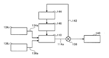
- FIG. 3 is a block diagram showing an outline of a supply path of fuel gas, liquid fuel, and EGR gas to the cylinder 110.
- the fuel gas storage unit 134 and the liquid fuel storage unit 136 are configured by, for example, tanks, the fuel gas storage unit 134 stores fuel gas, and the liquid fuel storage unit 136 stores liquid fuel.
- the fuel gas stored in the fuel gas storage section 134 and the liquid fuel stored in the liquid fuel storage section 136 pass through the fuel gas supply path 134a and the liquid fuel supply path 136a, respectively, into the cylinder 110. Supplied.
- the exhaust passage 114 a is an exhaust gas passage communicating with the exhaust port 114.
- a three-way valve 138 is provided in the exhaust flow path 114a, and the three-way valve 138 guides exhaust gas generated by combustion in the combustion chamber 124 and exhausted outside the cylinder 110 from the exhaust port 114 to the exhaust manifold 140 side. .
- the three-way valve 138 guides a part of the exhaust gas to the reflux path 142 that returns to the cylinder 110.
- the exhaust gas recirculated to the cylinder 110 is referred to as EGR gas.
- the opening degree of the three-way valve 138 is adjusted according to the injection amount of EGR gas injected into the cylinder 110 according to the control of the supply control unit 130, for example.
- the reflux path 142 is provided with a compressor 144 and a heat exchanger 146, and exhaust gas (EGR gas) flowing through the reflux path 142 becomes high pressure by the compressor 144 and is cooled by the heat exchanger 146. After that, it is supplied into the cylinder 110.
- exhaust gas EGR gas
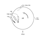
- FIG. 4A and 4B are diagrams for explaining the arrangement of the supply units in the combustion chamber 124.
- FIG. 4A shows a cross section taken along line IV (a) -IV (a) of FIG.
- FIG. 4B shows a view taken in the direction of arrow IV (b) in FIG. 4A. 4A and 4B, only the combustion chamber 124 and each supply part in the cylinder 110 are schematically shown for easy understanding.
- the cylinder 110 (cylinder head 110a) is provided with a liquid fuel supply unit 148, a fuel gas supply unit 150 (gas supply unit), and an EGR supply unit 152 (gas supply unit). ing.
- Each of the supply units (liquid fuel supply unit 148, fuel gas supply unit 150, and EGR supply unit 152) is composed of an injection nozzle and is operated under the control of the supply control unit 130.
- the liquid fuel supply unit 148 communicates with the downstream end of the liquid fuel supply path 136a, and injects (supply) the liquid fuel stored in the liquid fuel storage unit 136 into the cylinder 110 (combustion chamber 124).
- the fuel gas supply unit 150 communicates with the downstream end of the fuel gas supply path 134a, and injects the fuel gas stored in the fuel gas storage unit 134 into the cylinder 110 (combustion chamber 124).
- the EGR supply unit 152 includes two injection nozzles (a first EGR supply unit 152a and a second EGR supply unit 152b), which communicate with the downstream end of the return path 142, respectively.
- the circulating EGR gas is injected into the cylinder 110 (combustion chamber 124).
- a swirl flow is generated in the combustion chamber 124 due to the active gas flowing from the scavenging port 120.
- the first EGR supply unit 152a is disposed upstream of the fuel gas supply unit 150 in the flow direction of the swirl flow, for example, within a range of a half circumference of the cylinder 110.
- the second EGR supply unit 152b is disposed slightly upstream of the liquid fuel supply unit 148 in the flow direction of the swirl flow, for example, within a range of a half circumference of the cylinder 110. This range is, for example, a region up to half of the circumferential direction of the cylinder 110 on the upstream side in the swirl flow direction starting from the position of the liquid fuel supply unit 148.
- FIG. 5A and 5B are diagrams for explaining the supply of liquid fuel, fuel gas, and EGR gas to the combustion chamber 124.
- FIG. 5A EGR gas is first injected from the first EGR supply unit 152a and the second EGR supply unit 152b. Strictly speaking, after the EGR gas is injected from the first EGR supply unit 152a, the EGR gas is injected from the second EGR supply unit 152b.
- the liquid fuel is injected from the liquid fuel supply unit 148.
- fuel gas is injected from the fuel gas supply unit 150.
- the EGR gas injected from the second EGR supply unit 152b flows along the swirl flow in the liquid fuel injection direction of the liquid fuel supply unit 148, and the liquid fuel supply unit 148 includes the EGR gas.
- a liquid fuel is injected toward it.
- the EGR gas injected from the first EGR supply unit 152a flows along the swirl flow, and the fuel gas supply unit 150 faces the EGR gas. To inject fuel gas.
- the concentration of EGR gas locally increases around the liquid fuel and fuel gas supplied into the cylinder 110.
- the local and excessive temperature rise is suppressed due to the lowering of the oxygen concentration around the fuel gas and liquid fuel, and the influence of a gas having a large specific heat such as carbon dioxide gas or water vapor contained in the EGR gas.
- the amount of generation is reduced.
- the EGR gas is supplied only to the vicinity of the portion of the combustion chamber 124 where the liquid fuel and the fuel gas are supplied first. Therefore, it is possible to suppress the supply amount of EGR gas as compared with the configuration in which EGR gas is supplied to the entire combustion chamber 124.
- the first EGR supply unit 152a and the second EGR supply unit 152b are provided upstream of the fuel gas supply unit 150 and the liquid fuel supply unit 148 in the swirl flow, respectively. For this reason, the fuel gas and the liquid fuel are injected into the EGR gas that flows along the swirl flow and is appropriately diffused. As a result, the fuel gas or the liquid fuel easily comes into contact with the EGR gas, and the amount of NOx generated is further reduced.
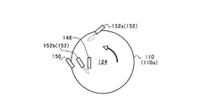
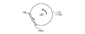
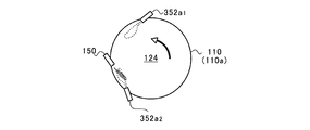
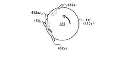
- 6A to 6C are diagrams for explaining the arrangement of the supply units in the first modification, the second modification, and the third modification of the present embodiment. 6A to 6C, illustration of the liquid fuel supply unit 148 and the second EGR supply unit 152b is omitted for easy understanding.
- the first EGR supply unit 252a is disposed downstream of the fuel gas supply unit 150 in the flow direction of the swirl flow. Then, the first EGR supply unit 252a injects EGR gas toward the upstream side in the swirl flow direction. As described above, the first EGR supply unit 252a may be disposed downstream of the fuel gas supply unit 150 in the swirl flow.
- the first EGR supply unit 252a is arranged in a direction substantially opposite to the fuel gas supply unit 150 in the fuel gas injection direction. However, at least the positional relationship may be such that the flow path of the fuel gas injected from the fuel gas supply section 150 intersects the flow path of the EGR gas injected from the first EGR supply section 252a.
- the first EGR supply unit 352a1 is arranged upstream of the fuel gas supply unit 150 in the flow direction of the swirl flow, and the first EGR supply unit 352a2 is arranged downstream.
- the first EGR supply unit 352a1 on the upstream side injects EGR gas toward the downstream side in the flow direction of the swirl flow, and the first EGR supply unit 352a2 on the downstream side has the EGR gas toward the upstream side in the flow direction of the swirl flow. Inject.
- first EGR supply parts 452a1 and 452a2 are arranged on the upstream side in the swirl flow direction from the fuel gas supply part 150, and the first EGR supply is provided on the downstream side.
- Part 452a3 is arranged.
- the first EGR supply units 452a1 and 452a2 on the upstream side inject EGR gas toward the downstream side in the flow direction of the swirl flow, and the first EGR supply unit 452a3 on the downstream side moves toward the upstream side in the flow direction of the swirl flow. EGR gas is injected.
- two or more first EGR supply units 352a1, 352a2, 452a1, 452a2, 452a3 may be arranged.
- the first EGR supply units 252a, 352a1, 352a2, 452a1, 452a2, and 452a3 are disposed at positions where the fuel gas is injected from the fuel gas supply unit 150.
- the arrangement and injection timing are set so that the EGR gas is located in a properly diffused state.
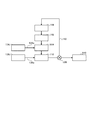
- FIG. 7 is a block diagram showing an outline of a supply path of fuel gas, liquid fuel, and EGR gas to the cylinder 110 in the fourth modification of the present embodiment.
- a mixing chamber 554 is provided on the downstream side of the heat exchanger 146 in the reflux path 142.
- the fuel gas supply path 534 a is connected to the mixing chamber 554.
- the mixing chamber 554 the EGR gas supplied from the heat exchanger 146 and the fuel gas supplied from the fuel gas storage unit 134 are mixed.
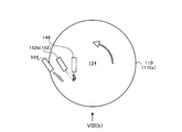
- FIGS. 8A and 8B are views for explaining the arrangement of the supply parts in the combustion chamber 124 in the fourth modification.
- FIG. 8A shows a cross-section at a position corresponding to FIG. 4A in the fourth modified example
- FIG. 8B shows a VIII (b) arrow view of FIG. 8A.
- FIG. 8A and B only the combustion chamber 124 and each supply part in the cylinder 110 are schematically shown for easy understanding.
- the gas supply unit 556 injects into the cylinder 110 a premixed gas of fuel gas and EGR gas mixed in the mixing chamber 554 that communicates with the downstream end of the reflux path 142 and flows through the downstream end of the reflux path 142. .
- the configuration in which the swirl flow is generated by the scavenging port 120 has been described, but the configuration in which the scavenging port 120 extends in the radial direction of the cylinder 110 and does not generate the swirl flow may be employed.
- the present disclosure can be used for a reciprocating engine in which a piston reciprocates due to an explosion pressure of fuel.
Landscapes
- Engineering & Computer Science (AREA)
- Chemical & Material Sciences (AREA)
- Combustion & Propulsion (AREA)
- Mechanical Engineering (AREA)
- General Engineering & Computer Science (AREA)
- Oil, Petroleum & Natural Gas (AREA)
- Exhaust-Gas Circulating Devices (AREA)
- Output Control And Ontrol Of Special Type Engine (AREA)
- Combustion Methods Of Internal-Combustion Engines (AREA)
- Electrical Control Of Air Or Fuel Supplied To Internal-Combustion Engine (AREA)
Abstract
Description
本願は、2014年9月18日に日本に出願された特願2014-190325号に基づき優先権を主張し、その内容をここに援用する。
ピストン112には、ピストンロッド112aの一端が固定されている。ピストンロッド112aは、不図示のクロスヘッドに連結されており、ピストン112がシリンダ110内を摺動しつつ往復動すると、クロスヘッドおよび連結棒を介してクランクシャフトが回転する。このようなクロスヘッド型のレシプロエンジンでは、シリンダ110内でのストロークを比較的長く形成することができ、ピストン112に作用する側圧をクロスヘッドに受けさせることが可能なので、ユニフロー掃気式2サイクルエンジン100の高出力化を図ることができる。
110 シリンダ
112 ピストン
120 掃気ポート
124 燃焼室
148 液体燃料供給部
150 燃料ガス供給部(ガス供給部)
152 EGR供給部(ガス供給部)
152a、252a、352a1、352a2、452a1、452a2、452a3 第1EGR供給部
152b 第2EGR供給部
556 ガス供給部
Claims (7)
- シリンダ内に形成される燃焼室で生じる爆発圧力により、前記シリンダ内でピストンが往復動するレシプロエンジンであって、
液体燃料を前記燃焼室に供給する液体燃料供給部と、
前記燃焼室における燃焼により生じ、前記燃焼室から排気された排気ガスであるEGRガス、および、燃料ガスを前記シリンダ内に供給するガス供給部と、
を備えるレシプロエンジン。 - 前記ガス供給部は、
前記EGRガスを前記シリンダ内に供給するEGR供給部と、
前記燃料ガスを前記シリンダ内に供給する燃料ガス供給部と、
を含む請求項1に記載のレシプロエンジン。 - 前記液体燃料供給部は、前記EGR供給部から前記シリンダ内に供給されたEGRガスに向かって、前記液体燃料を供給する請求項2に記載のレシプロエンジン。
- 前記燃料ガス供給部は、前記EGR供給部から前記シリンダ内に供給されたEGRガスに向かって、前記燃料ガスを供給する請求項2に記載のレシプロエンジン。
- 前記燃料ガス供給部は、前記EGR供給部から前記シリンダ内に供給されたEGRガスに向かって、前記燃料ガスを供給する請求項3に記載のレシプロエンジン。
- 前記シリンダに形成され、前記シリンダ内から活性ガスを流入させるとともに、この活性ガスによってスワール流を生じさせる掃気ポートをさらに備え、
前記EGR供給部は、前記燃料ガス供給部および前記液体燃料供給部の少なくとも一方より、前記スワール流の上流側に配置されている請求項2から5のいずれか1項に記載のレシプロエンジン。 - 前記ガス供給部は、前記EGRガスを前記燃料ガスと混合した予混合ガスを、前記シリンダ内に供給する請求項1に記載のレシプロエンジン。
Priority Applications (5)
| Application Number | Priority Date | Filing Date | Title |
|---|---|---|---|
| KR1020177005244A KR101912910B1 (ko) | 2014-09-18 | 2015-09-18 | 왕복 엔진 |
| DK15842525.6T DK3196436T3 (en) | 2014-09-18 | 2015-09-18 | Reciprocating motor |
| JP2016548964A JP6460114B2 (ja) | 2014-09-18 | 2015-09-18 | レシプロエンジン |
| CN201580049669.2A CN106687672B (zh) | 2014-09-18 | 2015-09-18 | 往复式发动机 |
| EP15842525.6A EP3196436B1 (en) | 2014-09-18 | 2015-09-18 | Reciprocating engine |
Applications Claiming Priority (2)
| Application Number | Priority Date | Filing Date | Title |
|---|---|---|---|
| JP2014-190325 | 2014-09-18 | ||
| JP2014190325 | 2014-09-18 |
Publications (1)
| Publication Number | Publication Date |
|---|---|
| WO2016043312A1 true WO2016043312A1 (ja) | 2016-03-24 |
Family
ID=55533348
Family Applications (1)
| Application Number | Title | Priority Date | Filing Date |
|---|---|---|---|
| PCT/JP2015/076677 Ceased WO2016043312A1 (ja) | 2014-09-18 | 2015-09-18 | レシプロエンジン |
Country Status (6)
| Country | Link |
|---|---|
| EP (1) | EP3196436B1 (ja) |
| JP (1) | JP6460114B2 (ja) |
| KR (1) | KR101912910B1 (ja) |
| CN (1) | CN106687672B (ja) |
| DK (1) | DK3196436T3 (ja) |
| WO (1) | WO2016043312A1 (ja) |
Cited By (1)
| Publication number | Priority date | Publication date | Assignee | Title |
|---|---|---|---|---|
| JP7500891B1 (ja) | 2023-02-10 | 2024-06-17 | マン・エナジー・ソリューションズ、フィリアル・エフ・マン・エナジー・ソリューションズ・エスイー、ティスクランド | 内燃機関 |
Families Citing this family (3)
| Publication number | Priority date | Publication date | Assignee | Title |
|---|---|---|---|---|
| CN109184962B (zh) * | 2018-09-27 | 2021-01-19 | 潍柴重机股份有限公司 | 废气缸内直喷湍流燃烧系统及方法 |
| CN110630399A (zh) * | 2019-10-30 | 2019-12-31 | 中船动力研究院有限公司 | 柴油机直流扫气结构及柴油机 |
| JP7813574B2 (ja) * | 2021-12-27 | 2026-02-13 | 株式会社ジャパンエンジンコーポレーション | ガスエンジン |
Citations (7)
| Publication number | Priority date | Publication date | Assignee | Title |
|---|---|---|---|---|
| JPS6473167A (en) * | 1987-07-30 | 1989-03-17 | Avl Verbrennungskraft Messtech | Two cycle engine |
| JPH06257520A (ja) * | 1993-03-05 | 1994-09-13 | Mazda Motor Corp | 2サイクルエンジン |
| JP2009052520A (ja) * | 2007-08-29 | 2009-03-12 | Mitsubishi Heavy Ind Ltd | 4サイクルegr混合式ガスエンジン |
| JP2010255442A (ja) * | 2009-04-21 | 2010-11-11 | Honda Motor Co Ltd | 内燃機関の制御装置 |
| JP2012154189A (ja) * | 2011-01-24 | 2012-08-16 | Ihi Corp | 2サイクルエンジン |
| JP2012154188A (ja) * | 2011-01-24 | 2012-08-16 | Ihi Corp | 2サイクルエンジン |
| JP2013133708A (ja) * | 2011-12-26 | 2013-07-08 | Daihatsu Motor Co Ltd | 内燃機関 |
Family Cites Families (10)
| Publication number | Priority date | Publication date | Assignee | Title |
|---|---|---|---|---|
| KR20020081526A (ko) * | 2001-04-18 | 2002-10-28 | 한국기계연구원 | 내연기관의 배기가스 보조 연료분사 장치 |
| US7188587B1 (en) * | 2005-11-30 | 2007-03-13 | Delphi Technologies, Inc. | Methods for operating a compression ignition engine |
| JP4501950B2 (ja) * | 2007-03-27 | 2010-07-14 | 日産自動車株式会社 | 内燃機関の燃焼制御装置 |
| US7743753B2 (en) * | 2008-03-31 | 2010-06-29 | Caterpillar Inc | Ignition system utilizing igniter and gas injector |
| CA2807879C (en) * | 2010-08-16 | 2018-12-04 | Westport Power Inc. | Gaseous-fuelled stoichiometric compression ignition internal combustion engine |
| DE102011003909B4 (de) * | 2011-02-10 | 2018-05-30 | Man Diesel & Turbo Se | Zweitaktbrennkraftmaschine und Verfahren zum Betreiben derselben |
| BR112013031867A2 (pt) * | 2011-06-14 | 2017-07-25 | Wsc Three S A | método para combustão supercrítica de diesel |
| JP5708466B2 (ja) | 2011-12-14 | 2015-04-30 | 株式会社デンソー | デュアルインジェクタ |
| KR101338719B1 (ko) * | 2011-12-15 | 2013-12-06 | 현대자동차주식회사 | 디젤-가솔린 복합연료 엔진 및 이의 예혼합 압축 착화 혼합 연소 제어방법 |
| FI124730B (en) * | 2013-01-22 | 2014-12-31 | Wärtsilä Finland Oy | A method of operating a piston engine and a piston engine |
-
2015
- 2015-09-18 CN CN201580049669.2A patent/CN106687672B/zh active Active
- 2015-09-18 DK DK15842525.6T patent/DK3196436T3/en active
- 2015-09-18 WO PCT/JP2015/076677 patent/WO2016043312A1/ja not_active Ceased
- 2015-09-18 JP JP2016548964A patent/JP6460114B2/ja active Active
- 2015-09-18 EP EP15842525.6A patent/EP3196436B1/en active Active
- 2015-09-18 KR KR1020177005244A patent/KR101912910B1/ko active Active
Patent Citations (7)
| Publication number | Priority date | Publication date | Assignee | Title |
|---|---|---|---|---|
| JPS6473167A (en) * | 1987-07-30 | 1989-03-17 | Avl Verbrennungskraft Messtech | Two cycle engine |
| JPH06257520A (ja) * | 1993-03-05 | 1994-09-13 | Mazda Motor Corp | 2サイクルエンジン |
| JP2009052520A (ja) * | 2007-08-29 | 2009-03-12 | Mitsubishi Heavy Ind Ltd | 4サイクルegr混合式ガスエンジン |
| JP2010255442A (ja) * | 2009-04-21 | 2010-11-11 | Honda Motor Co Ltd | 内燃機関の制御装置 |
| JP2012154189A (ja) * | 2011-01-24 | 2012-08-16 | Ihi Corp | 2サイクルエンジン |
| JP2012154188A (ja) * | 2011-01-24 | 2012-08-16 | Ihi Corp | 2サイクルエンジン |
| JP2013133708A (ja) * | 2011-12-26 | 2013-07-08 | Daihatsu Motor Co Ltd | 内燃機関 |
Cited By (2)
| Publication number | Priority date | Publication date | Assignee | Title |
|---|---|---|---|---|
| JP7500891B1 (ja) | 2023-02-10 | 2024-06-17 | マン・エナジー・ソリューションズ、フィリアル・エフ・マン・エナジー・ソリューションズ・エスイー、ティスクランド | 内燃機関 |
| JP2024114665A (ja) * | 2023-02-10 | 2024-08-23 | マン・エナジー・ソリューションズ、フィリアル・エフ・マン・エナジー・ソリューションズ・エスイー、ティスクランド | 内燃機関 |
Also Published As
| Publication number | Publication date |
|---|---|
| EP3196436A4 (en) | 2018-03-14 |
| EP3196436B1 (en) | 2018-12-05 |
| DK3196436T3 (en) | 2019-03-04 |
| EP3196436A1 (en) | 2017-07-26 |
| CN106687672B (zh) | 2019-08-13 |
| CN106687672A (zh) | 2017-05-17 |
| JPWO2016043312A1 (ja) | 2017-04-27 |
| KR20170036057A (ko) | 2017-03-31 |
| KR101912910B1 (ko) | 2018-10-29 |
| JP6460114B2 (ja) | 2019-01-30 |
Similar Documents
| Publication | Publication Date | Title |
|---|---|---|
| JP6115045B2 (ja) | ユニフロー掃気式2サイクルエンジン | |
| JP6075086B2 (ja) | ユニフロー掃気式2サイクルエンジンおよびユニフロー掃気式2サイクルエンジンの燃料噴射方法 | |
| JP5983196B2 (ja) | ユニフロー掃気式2サイクルエンジン | |
| JP6019941B2 (ja) | ユニフロー掃気式2サイクルエンジン | |
| JP2013253529A (ja) | 2ストロークユニフローエンジン | |
| JP2012154189A (ja) | 2サイクルエンジン | |
| JP6460114B2 (ja) | レシプロエンジン | |
| JP2012154188A (ja) | 2サイクルエンジン | |
| JP2016211680A (ja) | クロスヘッド型エンジン | |
| JP7474830B2 (ja) | 燃料噴射装置 | |
| JP2014005818A (ja) | 2サイクルエンジン | |
| KR101809697B1 (ko) | 유니플로 소기식 2사이클 엔진 | |
| EP3098415B1 (en) | Uniflow scavenging 2-cycle engine | |
| JP2014092072A (ja) | ディーゼルエンジン | |
| JP6003288B2 (ja) | ユニフロー掃気式2サイクルエンジン | |
| JP2016089642A (ja) | ユニフロー掃気式2サイクルエンジン | |
| JP6492542B2 (ja) | ユニフロー掃気式2サイクルエンジン | |
| JP2020153353A (ja) | ユニフロー掃気式2サイクルエンジン |
Legal Events
| Date | Code | Title | Description |
|---|---|---|---|
| 121 | Ep: the epo has been informed by wipo that ep was designated in this application |
Ref document number: 15842525 Country of ref document: EP Kind code of ref document: A1 |
|
| ENP | Entry into the national phase |
Ref document number: 2016548964 Country of ref document: JP Kind code of ref document: A |
|
| ENP | Entry into the national phase |
Ref document number: 20177005244 Country of ref document: KR Kind code of ref document: A |
|
| REEP | Request for entry into the european phase |
Ref document number: 2015842525 Country of ref document: EP |
|
| WWE | Wipo information: entry into national phase |
Ref document number: 2015842525 Country of ref document: EP |
|
| NENP | Non-entry into the national phase |
Ref country code: DE |