WO2016046966A1 - 検体抽出キット、および、検体抽出方法 - Google Patents
検体抽出キット、および、検体抽出方法 Download PDFInfo
- Publication number
- WO2016046966A1 WO2016046966A1 PCT/JP2014/075672 JP2014075672W WO2016046966A1 WO 2016046966 A1 WO2016046966 A1 WO 2016046966A1 JP 2014075672 W JP2014075672 W JP 2014075672W WO 2016046966 A1 WO2016046966 A1 WO 2016046966A1
- Authority
- WO
- WIPO (PCT)
- Prior art keywords
- cylindrical container
- extraction
- clamping
- bent
- container
- Prior art date
- Legal status (The legal status is an assumption and is not a legal conclusion. Google has not performed a legal analysis and makes no representation as to the accuracy of the status listed.)
- Ceased
Links
Images








Classifications
-
- G—PHYSICS
- G01—MEASURING; TESTING
- G01N—INVESTIGATING OR ANALYSING MATERIALS BY DETERMINING THEIR CHEMICAL OR PHYSICAL PROPERTIES
- G01N1/00—Sampling; Preparing specimens for investigation
- G01N1/28—Preparing specimens for investigation including physical details of (bio-)chemical methods covered elsewhere, e.g. G01N33/50, C12Q
- G01N1/286—Preparing specimens for investigation including physical details of (bio-)chemical methods covered elsewhere, e.g. G01N33/50, C12Q involving mechanical work, e.g. chopping, disintegrating, compacting, homogenising
-
- B—PERFORMING OPERATIONS; TRANSPORTING
- B01—PHYSICAL OR CHEMICAL PROCESSES OR APPARATUS IN GENERAL
- B01L—CHEMICAL OR PHYSICAL LABORATORY APPARATUS FOR GENERAL USE
- B01L3/00—Containers or dishes for laboratory use, e.g. laboratory glassware; Droppers
- B01L3/50—Containers for the purpose of retaining a material to be analysed, e.g. test tubes
- B01L3/502—Containers for the purpose of retaining a material to be analysed, e.g. test tubes with fluid transport, e.g. in multi-compartment structures
- B01L3/5029—Containers for the purpose of retaining a material to be analysed, e.g. test tubes with fluid transport, e.g. in multi-compartment structures using swabs
-
- B—PERFORMING OPERATIONS; TRANSPORTING
- B02—CRUSHING, PULVERISING, OR DISINTEGRATING; PREPARATORY TREATMENT OF GRAIN FOR MILLING
- B02C—CRUSHING, PULVERISING, OR DISINTEGRATING IN GENERAL; MILLING GRAIN
- B02C19/00—Other disintegrating devices or methods
- B02C19/0006—Crushing by endless flexible members
-
- G—PHYSICS
- G01—MEASURING; TESTING
- G01N—INVESTIGATING OR ANALYSING MATERIALS BY DETERMINING THEIR CHEMICAL OR PHYSICAL PROPERTIES
- G01N1/00—Sampling; Preparing specimens for investigation
- G01N1/02—Devices for withdrawing samples
- G01N1/10—Devices for withdrawing samples in the liquid or fluent state
-
- G—PHYSICS
- G01—MEASURING; TESTING
- G01N—INVESTIGATING OR ANALYSING MATERIALS BY DETERMINING THEIR CHEMICAL OR PHYSICAL PROPERTIES
- G01N1/00—Sampling; Preparing specimens for investigation
- G01N1/28—Preparing specimens for investigation including physical details of (bio-)chemical methods covered elsewhere, e.g. G01N33/50, C12Q
-
- G—PHYSICS
- G01—MEASURING; TESTING
- G01N—INVESTIGATING OR ANALYSING MATERIALS BY DETERMINING THEIR CHEMICAL OR PHYSICAL PROPERTIES
- G01N33/00—Investigating or analysing materials by specific methods not covered by groups G01N1/00 - G01N31/00
- G01N33/48—Biological material, e.g. blood, urine; Haemocytometers
-
- B—PERFORMING OPERATIONS; TRANSPORTING
- B01—PHYSICAL OR CHEMICAL PROCESSES OR APPARATUS IN GENERAL
- B01L—CHEMICAL OR PHYSICAL LABORATORY APPARATUS FOR GENERAL USE
- B01L2300/00—Additional constructional details
- B01L2300/06—Auxiliary integrated devices, integrated components
- B01L2300/0609—Holders integrated in container to position an object
-
- B—PERFORMING OPERATIONS; TRANSPORTING
- B01—PHYSICAL OR CHEMICAL PROCESSES OR APPARATUS IN GENERAL
- B01L—CHEMICAL OR PHYSICAL LABORATORY APPARATUS FOR GENERAL USE
- B01L2400/00—Moving or stopping fluids
- B01L2400/04—Moving fluids with specific forces or mechanical means
- B01L2400/0475—Moving fluids with specific forces or mechanical means specific mechanical means and fluid pressure
- B01L2400/0481—Moving fluids with specific forces or mechanical means specific mechanical means and fluid pressure squeezing of channels or chambers
-
- B—PERFORMING OPERATIONS; TRANSPORTING
- B01—PHYSICAL OR CHEMICAL PROCESSES OR APPARATUS IN GENERAL
- B01L—CHEMICAL OR PHYSICAL LABORATORY APPARATUS FOR GENERAL USE
- B01L3/00—Containers or dishes for laboratory use, e.g. laboratory glassware; Droppers
- B01L3/50—Containers for the purpose of retaining a material to be analysed, e.g. test tubes
- B01L3/505—Flexible containers without fluid transport within
-
- G—PHYSICS
- G01—MEASURING; TESTING
- G01N—INVESTIGATING OR ANALYSING MATERIALS BY DETERMINING THEIR CHEMICAL OR PHYSICAL PROPERTIES
- G01N1/00—Sampling; Preparing specimens for investigation
- G01N1/02—Devices for withdrawing samples
- G01N2001/028—Sampling from a surface, swabbing, vaporising
-
- G—PHYSICS
- G01—MEASURING; TESTING
- G01N—INVESTIGATING OR ANALYSING MATERIALS BY DETERMINING THEIR CHEMICAL OR PHYSICAL PROPERTIES
- G01N1/00—Sampling; Preparing specimens for investigation
- G01N1/28—Preparing specimens for investigation including physical details of (bio-)chemical methods covered elsewhere, e.g. G01N33/50, C12Q
- G01N1/286—Preparing specimens for investigation including physical details of (bio-)chemical methods covered elsewhere, e.g. G01N33/50, C12Q involving mechanical work, e.g. chopping, disintegrating, compacting, homogenising
- G01N2001/2866—Grinding or homogeneising
Definitions
- the present disclosure relates to a specimen extraction kit and a specimen extraction method for extracting a specimen in a flexible cylindrical container.
- a specimen extraction kit includes a flexible cylindrical container configured to store an extraction liquid, an extraction target member stored in the cylindrical container, and the cylindrical container.
- the cylindrical container provided in each of a plurality of sandwiching portions opposed to each other across a peripheral wall, an elastically deformable coupling portion coupling between the sandwiching portions facing each other, and the sandwiching portions facing each other And a bending portion configured to bend the extraction target member.
- the cylindrical container and the extraction target member are bent by the bending portion in a state where the extraction target member is accommodated in the cylindrical container.
- the degree of deformation of the extraction target member is greater than that of the extraction mode in which the extraction target member is simply crushed with a finger or the like, and therefore the specimen extraction efficiency is increased.
- the sample extraction kit may include a handling portion that is provided in the holding portions facing each other and further handles the bent cylindrical container and the extraction target member. According to this configuration, since the bent extraction target member is further handled, the specimen is more easily pushed out from the extracted extraction target member. As a result, the sample extraction efficiency is improved as compared with the extraction mode in which the extraction target member is simply bent.
- the bent portion is a protruding portion that protrudes from each of the holding portions facing each other toward the other holding portion, and bends and handles the cylindrical container and the extraction target member.
- the protrusion provided in each of the sandwiching portions facing each other exhibits a function of bending the extraction target member and a function of handling the extraction target member. Therefore, the configuration of the sample extraction kit is easier than the configuration in which these two functions are configured by different parts.
- the protrusions provided on the sandwiching portions facing each other are arranged at different positions in the extending direction of the cylindrical container, and the sandwiching portions facing each other approach each other, thereby The cylindrical container and the extraction target member are folded and handled.
- the protruding portions provided in the respective sandwiching portions bend and handle the cylindrical container. Therefore, the procedure required for sample extraction can be simplified compared to the extraction procedure in which the bending of the extraction target member and the handling of the extraction target member are performed separately.
- the cylindrical container has a portion that gradually narrows toward the lower end, and the cylindrical container is lower than the center of the cylindrical container in the extending direction of the cylindrical container.
- the cylindrical container is bent and handled.
- the cylindrical container having a portion that gradually narrows toward the lower end is folded at the lower side in the cylindrical container, the cylindrical container is folded at the upper side in the cylindrical container. In comparison, the user's load required for bending the cylindrical container is reduced.
- a specimen extraction method includes a flexible cylindrical container configured to store an extraction liquid and a plurality of extraction target members stored in the cylindrical container facing each other.
- the sample is extracted from the extraction target member by bending the cylindrical container and the extraction target member by being sandwiched by a sandwiching unit.
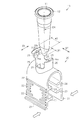
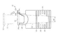
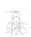
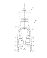
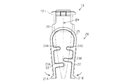
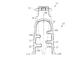
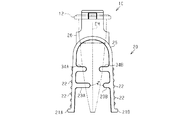
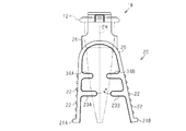
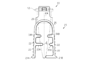
- the cylindrical container is a perspective view in a state where it is separated from the holding member. It is a partially broken front view of a clamping member. It is a schematic diagram for demonstrating the process in which a cylindrical container is fixed to a clamping member. It is a side view of the clamping member for demonstrating the relationship between a cylindrical container and a clamping member. It is a schematic diagram for demonstrating the process in which a cylindrical container is fixed to a clamping member. It is a schematic diagram for demonstrating the process in which a cylindrical container is fixed to a clamping member. It is a schematic diagram for demonstrating reduction of the clearance gap between two clamping pieces.
- the sample extraction kit includes a cylindrical container 10 configured to store an extraction liquid, a clamping member 20 that assists sample extraction, and an extraction member EM.
- the extraction target member EM may be any member that can be immersed in the extraction liquid in the cylindrical container 10 and can elute the specimen. Examples thereof include paper points, cotton swabs, flocked swabs, sponges, paper, and nonwoven fabrics.
- the tubular container 10 is a flexible tubular body having an opening at the upper end and a bottom at the lower end.
- the cylindrical container 10 has a portion that gradually narrows toward the lower end, and is formed in a flat cylindrical shape that is stretched in the long axis direction DF.
- a container opening 11, which is a circular hole, is formed at the upper end of the cylindrical container 10, and a flange portion 12 is formed around the container opening 11 over the entire circumferential direction of the cylindrical container 10.
- the lower end of the cylindrical container 10 has a width in the major axis direction DF set as a first container width W1, and a width in a direction perpendicular to the major axis direction DF set as a second container width W2 (see FIG. 4). Is done.
- variety in the major axis direction DF in the upper end is set as the 3rd container width W3
- the thickness in the cylindrical container 10 is set. It is set as the container thickness T.
- the width in the minor axis direction DV between the two bending ribs 23 in the extraction target member EM is set as the extraction target member thickness P.
- the forming material of the cylindrical container 10 may be a resin having flexibility, and for example, polyethylene, polypropylene, polyethylene terephthalate, polyvinyl chloride, silicon rubber, or the like is used.
- the cylindrical container 10 may be transparent or opaque. However, the cylindrical container 10 is transparent or transparent so that the user can visually confirm the position of the extraction target member EM and the state in which the specimen is eluted into the extraction liquid. It is preferable that it is translucent. Furthermore, a nozzle that guides the extract contained in the cylindrical container 10 to the outside may be attached to the upper end of the cylindrical container 10.
- the clamping member 20 may be a folded plate-like member having an inverted U-shaped cross section in a side view.
- polyethylene, polypropylene, ABS resin, polystyrene, AS resin, polycarbonate, polyethylene terephthalate, polyvinyl chloride, spring steel, or the like is used as a material for forming the holding member 20.
- the clamping member 20 has, for example, an inverted U shape.
- the sandwiching member 20 includes a connecting portion that can be, for example, a curved bent portion, and two sandwiching portions 21 that extend from the connecting portion toward two free end portions that are remote.
- the two clamping parts 21 may be flat plates facing each other.
- the outer surfaces of the two sandwiching portions 21 may be symmetrical with each other with respect to one plane along the axial line or the extending direction of the sandwiching member 20 or the cylindrical container 10.
- the outer surface of each clamping part 21 may be roughened, for example, the some anti-slip rib 22 orthogonal to the extension direction of the clamping part 21 may be formed.
- Bending ribs 23 are formed on the inner side surfaces of the two sandwiching portions 21 as protruding portions protruding inward. At a position different from the bending rib 23 (for example, the upper side of the bending rib 23), a guide rib 24 protruding inward from the inner side surface of the holding portion 21 is formed. Each bending rib 23 and each guide rib 24 are formed over the entire clamping portion 21 along the long axis direction DF.
- each clamping portion 21 is connected to a leaf spring portion 25 as a connecting portion that is bent in a shape protruding upward.
- the leaf spring portion 25 is connected over the entire sandwiching portion 21 in a direction orthogonal to the extending direction, and the two sandwiching portions 21 and the leaf spring portion 25 are integrally molded.
- each of the two holding portions 21 is displaced with the leaf spring portion 25 as a substantially swinging center so that the tips of the two holding portions 21 are particularly close to each other and the two holding portions 21 approach each other. Gradually increases from the proximal end to the distal end of the sandwiching portion 21.
- An insertion tube portion 26 formed in a cylindrical shape extending upward from the leaf spring portion 25 is connected to the outer surface of the leaf spring portion 25.
- An insertion hole 27 that is a circular hole that penetrates the leaf spring portion 25 and leads to the gap between the two clamping portions 21 is formed inside the insertion tube portion 26.
- the insertion hole 27 is formed in such a size that the cylindrical container 10 can be inserted into and extracted from the insertion hole 27, and the inner diameter of the insertion hole 27 is substantially equal to the inner diameter of the flange portion 12 and the outside of the flange portion 12. Smaller than the diameter.
- Two cutouts 28 extending along the extending direction are formed on the peripheral wall of the insertion tube portion 26 at positions facing each other over substantially the entire extension direction of the insertion tube portion 26. Each notch 28 is formed, for example, in the same size as the user's fingertip.
- the insertion hole 27 is an example of a container receiving port.
- a restricting portion 29 is formed at the upper end of the insertion tube portion 26.
- the restricting portion 29 is formed only at one of the two portions sandwiched by the two notches 28 in the upper end portion of the insertion tube portion 26.
- the restricting portion 29 is a portion expanded from the upper end surface 26a of the insertion tube portion 26, and is formed in an arc surface shape in which an arc having an inner diameter larger than the inner diameter of the insertion tube portion 26 continues upward. .
- An operation piece 29 a extending toward the radially outer side of the insertion tube portion 26 and a locking claw 29 b extending toward the radially inner side of the insertion tube portion 26 are formed at the upper end portion of the restriction portion 29. Yes.
- the inner diameter Di of the restricting portion 29 formed in an arcuate shape is substantially equal to the outer diameter of the flange portion 12 in the cylindrical container 10.
- the inner surface of the restricting portion 29 and the outer peripheral surface of the flange portion 12 face each other, the downward movement of the flange portion 12 is restricted by the upper end surface 26a of the insertion tube portion 26, and the upward movement of the flange portion 12 is increased.
- the movement is restricted by a locking claw 29 b formed in the restricting portion 29.
- substantially the entire restricting portion 29 including the locking claws 29b is elastically deformed.
- substantially the entire restricting portion 29 bends outward and downward in the radial direction.
- limiting with respect to the movement of the cylindrical container 10 along the direction where the cylindrical container 10 is extended is cancelled
- Such a restricting portion 29 may be formed in both of the two portions sandwiched by the two notches 28 in the upper end portion of the insertion tube portion 26, and is inserted regardless of the number of the notches 28. Two or more upper end portions of the cylindrical portion 26 may be formed.
- the first bent rib 23 ⁇ / b> A and the first guide rib are directed toward the second clamping part 21 ⁇ / b> B that is the other clamping part 21.
- 24A protrudes.
- the second bent rib 23B and the second guide rib 24B protrude toward the first clamping part 21A.
- the first bent rib 23A and the second bent rib 23B function as a protruding portion that also serves as a bent portion and a handling portion.
- the container height in which the distance in the extending direction between the tip of the first clamping part 21A and the upper end surface 26a of the insertion cylinder part 26 is the length in the extending direction of the cylindrical container 10 is used.
- H the distance in the extending direction between the tip of the first clamping part 21A and the first bending rib 23A
- the distance between the tip of the first clamping part 21A and the first guide rib 24A is set as the first guide rib height H4A.
- the thickness along the extending direction of the first bending rib 23A is set as the first bending rib thickness T3A
- the thickness along the extending direction of the first guide rib 24A is set as the first guide rib thickness T4A. Is done.
- the distance in the extending direction between the tip of the second clamping part 21B and the second bending rib 23B is set as the second bending rib height H3B
- the tip of the second clamping part 21B and the second The distance in the extending direction between the two guide ribs 24B is set as the second guide rib height H4B
- the thickness along the extending direction of the second bent rib 23B is set as the second bent rib thickness T3B
- the thickness along the extending direction of the second guide rib 24B is set as the second guide rib thickness T4B. Is done.
- the distance in the extending direction between the first bent rib 23A and the second bent rib 23B is set as the bent width HC.
- the distance in the clamping direction between the tip of the first bent rib 23A and the tip of the second bent rib 23B is set as the clamping width WP.
- the distance in the clamping direction between the tip of the first guide rib 24A and the tip of the second guide rib 24B is set as the guide width WG.
- the first bent rib 23A and the second bent rib 23B are arranged at different positions in the extending direction, and the second bent rib height H3B is larger than the first bent rib height H3A.
- the first bent rib height H3A and the second bent rib height H3B satisfy the following formula 1 with respect to the container height H in order to make the cylindrical container 10 easier to bend and to increase the specimen extraction efficiency. It is preferable.
- the cylindrical container 10 can be bent even when the first bent rib height H3A is 0 mm.
- the first bending rib 23A and the second bending rib 23B bend the extraction target member EM to further handle the extraction target member EM, thereby further increasing the specimen extraction efficiency.
- the second bent rib height H3B satisfies the following formula 2.
- the first guide rib 24A and the second guide rib 24B are disposed at positions facing each other, and the first guide rib height H4A and the second guide rib height H4B are substantially equal.
- the first guide rib thickness T4A and the second guide rib thickness T4B are equal in order to prevent the relative position of the cylindrical container 10 with respect to the holding member 20 from varying every time the cylindrical container 10 is inserted.
- the guide width WG preferably satisfies the following formula 3 with respect to the first container width W1, the second container width W2, and the third container width W3 in the cylindrical container 10.
- the sandwiching width WP preferably satisfies the following formula 4 with respect to the guide width WG and the second container width W2.
- the guide width WG of the gap between the two guide ribs 24A and 24B is the minor axis at the lower end of the cylindrical container 10. It is larger than the second container width W2 in the direction DV, and the cylindrical container 10 is gradually narrowed toward the lower side of the cylindrical container 10. Therefore, when a force for further inserting the cylindrical container 10 is applied to the cylindrical container 10, as indicated by an arrow RF in FIG.
- the lower end of the cylindrical container 10 that has passed between the two guide ribs 24A and 24B is in a state where the minor axis direction DV and the clamping direction coincide with each other, and the gap between the two bent ribs 23A and 23B is also smooth.
- the flat surface of the cylindrical container 10 and the guide ribs 24A and 24B face each other, and the flat surface of the cylindrical container 10 and the bending ribs 23A and 23B face each other.
- the cylindrical container 10 is disposed in the gap between the two sandwiching portions 21.
- the cylindrical container 10 when the cylindrical container 10 is inserted into the gap between the two guide ribs 24A and 24B in a state where the major axis direction DF and the clamping direction in the cylindrical container 10 are orthogonal, the cylindrical container 10 does not rotate, The cylindrical container 10 is disposed in the gap between the two sandwiching portions 21 in a state where the flat surface of the cylindrical container 10 and the guide ribs 24A and 24B face each other.
- the relative positions of the two holding parts 21 and the cylindrical container 10 are aligned for each insertion of the cylindrical container 10, so that the two holding parts 21 and the cylindrical container 10 are The difference in the extraction result due to the difference in the relative position is suppressed for each insertion of the cylindrical container 10.
- the two sandwiching portions 21 are held by a finger, for example, along the direction approaching each other. Receive external force. And the leaf
- the distal ends of the two sandwiching portions 21 are particularly close to each other, and the degree of approach between the two sandwiching portions 21 is from the proximal end of the sandwiching portion 21 toward the distal end. Gradually grows. Therefore, as long as the above expression 4 is satisfied, the gap between the two bent ribs 23A and 23B is naturally smaller than the gap between the two guide ribs 24A and 24B.
- the cylindrical container 10 is bent by receiving pressure from the two bending ribs 23 ⁇ / b> A and 23 ⁇ / b> B.
- the extraction target member EM accommodated in the cylindrical container 10 is also bent along with the bending of the cylindrical container 10 and is handled by the tip of the first bent rib 23A.
- the degree of deformation in the extraction target member EM is greater than that in the configuration in which the extraction target member EM is simply crushed by a finger or the like and the cylindrical container 10 is not bent. Since it is handled in the extract, the specimen extraction efficiency is increased.
- the degree to which the extraction target member EM is crushed varies greatly depending on the size of the user's finger and the user's power, so the sample extraction efficiency is Each procedure is different from each other.
- the degree to which the extraction target member EM is crushed is maintained by mechanical pressurization, the specimen extraction efficiency is generally maintained for each extraction target member EM.
- the fulcrum for bending the cylindrical container 10 and the action point are the two bending ribs 23, so that the specimen extraction efficiency is increased.
- the position of the cylindrical container 10 in the extending direction is determined with respect to the holding member 20 by the engagement of the flange portion 12 and the insertion tube portion 26.
- the circumferential position of the cylindrical container 10 is determined with respect to the clamping member 20 by the guide of the cylindrical container 10 by the two guide ribs 24A and 24B. Therefore, it is possible to further suppress that the sample extraction efficiency differs from one user procedure to another.
- the cylindrical container 10 that gradually narrows toward the lower side is bent at the lower side in the cylindrical container 10, so that it is cylindrical at the upper side in the cylindrical container 10.
- the user's load required for bending the cylindrical container 10 is reduced.
- the cylindrical container 10 is bent in the gap between the two bent ribs 23A and 23B when the two sandwiching portions 21 approach each other, and the first bent rib 23A Handled by the tip.
- the extraction target member EM sandwiched between the inner surfaces of the cylindrical container 10 is also bent and handled by the inner surface of the cylindrical container 10. Therefore, the specimen extraction efficiency is further enhanced compared to the configuration in which the extraction target member EM is simply bent.
- Example 10 The sample extraction efficiency will be described using an example. After absorbing 4 ⁇ L of a constant concentration of bacteria into two paper points (length 30 mm), the two paper points are stored in a cylindrical container 10 (length 44 mm) and stored in the cylindrical container 10. The previous paper point was immersed in 400 ⁇ L of the extracted liquid. Next, after performing extraction processing on the paper point, 50 ⁇ L of the extracted liquid after the extraction processing is dropped onto the test device, and the line intensity, which is an indicator of the concentration of the sample, is measured after 15 minutes, and the line of the example Strength, i.e. sensitivity, was obtained. In addition, the line intensity
- test examples are made by using the following first to fifth explanatory variables in order to specify the line strength, that is, the factor (explanatory variable) for explaining the sensitivity, and using the conditions other than the explanatory variables as in the embodiment.
- the line strength at was obtained.
- regression analysis was performed using data obtained from 84 types of test examples.
- Table 1 shows the multiple regression coefficient and the P value for each factor obtained by the multiple regression analysis.
- the P value is a word generally used in statistics such as F test and t test. When the P value is smaller than 0.01, it is highly significant at a significance level of 1%. It can be said that there is a 99% probability (multiple regression equation applies).
- First explanatory variable number of extractions The number of times the cylindrical container 10 is manually squeezed or the number of times the cylindrical container 10 is bent by the holding member 20 is changed to 5, 10, 20, 30 times.
- Second explanatory variable second bent rib height H3B The second bent rib height H3B was changed to 7 mm, 9 mm, 11 mm, and 13 mm, and these second bent rib heights H3B were used as second explanatory variables.
- Third explanatory variable general thickness Thickness of the sandwiching member 20 other than the bending ribs 23A and 23B and the guide ribs 24A and 24B is changed to 1.0 mm and 1.5 mm. Was used as the third explanatory variable.
- first bending rib thickness T3A The first bent rib thickness T3A was changed to 2.0 mm and 2.5 mm, and these first bent rib thickness T3A was used as the fourth explanatory variable.
- Fifth explanatory variable bending elastic modulus of the leaf spring portion 25 The bending elastic modulus of the leaf spring portion 25 is changed to 800 MPa, 1200 MPa, 1600 MPa, and 2500 MPa, and the bending elastic modulus of these leaf spring portions 25 is used as the fifth explanatory variable. It was.
- the second bending rib height H3B is 11 mm
- the general thickness is 1.5 mm
- the first bending rib thickness T3A is 2.0 mm
- the bending elastic modulus of the leaf spring portion 25 is 2500 MPa.
- the sensitivity of was 0.70.
- the second bending rib height H3B is 11 mm
- the general thickness is 1.5 mm
- the first bending rib thickness T3A is 2.5 mm
- the bending elastic modulus of the leaf spring portion 25 is 2500 MPa.
- the sensitivity of was 0.80.
- the second bending rib height H3B is 11 mm
- the general thickness is 1.5 mm
- the first bending rib thickness T3A is 2.5 mm
- the bending elastic modulus of the leaf spring portion 25 is 800 MPa.
- the sensitivity of was 0.75.
- the second bending rib height H3B is 11 mm
- the general thickness is 1.0 mm
- the first bending rib thickness T3A is 2.0 mm
- the bending elastic modulus of the leaf spring portion 25 is 2500 MPa.
- the sensitivity of was 0.80.
- the multiple correlation coefficient R is 0.8644, which is very close to 1, and the determination coefficient R square value is 0.7472. It can be said that the fit of the regression equation by multiple regression analysis is good.
- the regression coefficient related to the second explanatory variable (second bending rib height H3B) is 0.0626, and the P value for the regression coefficient is 3.1364 ⁇ 10E-20. Since it was the smallest value ( ⁇ 0.01), it was confirmed that the second bending rib height H3B highly influenced the sensitivity at a significance level of 1%.
- the predicted value of sensitivity is higher as the second bent rib height H3B is larger, and the predicted value of sensitivity is almost saturated in the range where the second bent rib height H3B is 11 mm or more.
- the second bending rib height H3B is preferably set in a range of 50% or less of the container height H (44.0 mm), and is 20.0% or more and 35.0% or less of the container height H. More preferably, it is set in the range.
- the second bent rib height H3B is preferably set to a range of 75% or less of the height of the extract (20.0 mm), and in a range of 50% to 70% of the height of the extract. More preferably, it is set.
- the regression coefficient related to the fourth explanatory variable (first bent rib thickness T3A) is 0.1700, and the P value of the regression coefficient is 5.1238 ⁇ 10E-5 ( ⁇ 0. 01) and the second smallest value, it was confirmed that the first bent rib thickness T3A also affected the sensitivity at a significance level of 1%.
- the dispersion of the sample with the first bent rib thickness T3A of 2.5 mm is smaller than the dispersion of the sample with the first bent rib thickness T3A of 2.0 mm.
- the variance is 0.02
- the variance is Was 0.003.
- the one-sided P value is 1.05 ⁇ 10E-09 ( ⁇ 0.01), and the difference between these two types of samples is different at a significance level of 1%. It was recognized that there was. That is, the sensitivity variation due to the first bent rib thickness T3A of 2.0 mm is 0.02, whereas the sensitivity variation due to 2.5 mm is 0.003, which is about 1/10. Admitted.
- the average sensitivity value is 0.70 when the significance level is 1% and the first bending rib thickness T3A is 2.0 mm.
- the average value of the sensitivity at 2.5 mm was improved to 0.75. Therefore, it was recognized that the distance between the first bent rib 23A and the second bent rib 23B was narrowed, and the sensitivity was improved by handling the extraction target member EM.
- the extraction target member EM is also bent and handled when the cylindrical container 10 is bent, the sample is compared with a configuration in which the extraction target member EM is simply crushed by a finger or the like and the cylindrical container is not bent. Extraction efficiency is increased.
- the bending ribs 23A and 23B deform the cylindrical container 10 into a zigzag shape.
- the deformed cylindrical container 10 has a valley fold and a mountain fold alternately along the axis of the cylindrical container 10 (see the one-dot chain line in FIGS. 5 and 6).
- the distal end of the bending rib 23 ⁇ / b> A is configured to crush the cylindrical container 10 in cooperation with the non-tip portion (for example, the base end portion) of the bending rib 23 ⁇ / b> B.
- the extraction target member EM containing the specimen or having the specimen attached thereto is zigzag by the bent ribs 23A and 23B while being immersed in the extraction liquid in the cylindrical container 10. Transformed into Therefore, the specimen extraction efficiency from the extraction target member EM to the extraction liquid is improved.
- the cylindrical container 10 may return to an original shape.
- the embodiment described above can be implemented with the following modifications.
- the restricting portion 29 may be configured to restrict movement along the extending direction of the cylindrical container 10 by engagement with the flange portion 12, for example, a clamp that tightens the flange portion 12 over the entire circumference of the flange portion 12. May be provided separately in the insertion tube portion. Note that the restriction unit 29 may be omitted, and even with such a configuration, the effects according to the above (1) to (4) and the above (6) and (7) can be obtained. Compared with the configuration in which the portion 29 is provided, the configuration of the cylindrical container 10 and the configuration of the clamping member 20 are simple.
- the guide width WG may be larger than the first container width W1, and only needs to be smaller than the maximum value of the width in the long axis direction DF in the cylindrical container 10. Even with such a configuration, the effect according to the above (4) can be obtained.
- the guide width WG may be larger than the maximum value of the width in the long axis direction DF in the cylindrical container 10, or may be configured such that the two guide ribs 24A and 24B themselves are omitted. .
- the cylindrical container may have a thin cylindrical shape toward the lower side, or may have an enormous cylindrical shape on the lower side. Even with such a configuration, the effects according to the above (1) to (3) and (7) can be obtained.
- the above-mentioned formula 2 does not need to be satisfied as long as the above-mentioned formula 2 is satisfied when the two clamping parts 21 approach each other. Even with such a configuration, the effect according to the above (3) can be obtained.
- the bending width HC may be larger than twice the container wall thickness T in the entire range in which the two sandwiching portions 21 are displaced. Even with such a configuration, the effects according to the above (1), (2), (4) to (7) can be obtained.
- the extraction target member EM sandwiched between the inner side surfaces of the cylindrical container 10 is bent and handled on the inner side surface of the cylindrical container 10, the sample extraction efficiency is higher than the configuration in which the extraction target member EM is simply bent. Further enhanced.
- the part bent by the cylindrical container 10 may be above the center of the cylindrical container 10 in the extending direction. Even if it is such a structure, as long as extraction object member EM accommodated in the cylindrical container 10 is bent with the cylindrical container 10, the effect according to said (1), (3) to (7) is acquired. Further, in addition to the configuration in which the portion bent by the cylindrical container is below the center of the cylindrical container in the extending direction of the cylindrical container, the range of positions where the bending ribs are arranged is expanded, and thus The range of the extraction target member EM applied to the specimen extraction kit is expanded.
- two bent ribs 23A and 34A may be provided on the first holding part 21A, and two bent ribs 23B and 34B may be provided on the second holding part 21B.
- the width in the extending direction between the two bent ribs 34A and 34B may be the same as the bent width HC or may be different from each other.
- Two guide ribs 24A and 24B may be omitted.
- the two bent ribs 23 ⁇ / b> B and 34 ⁇ / b> B may be disposed between the two bent ribs 23 ⁇ / b> A and 34 ⁇ / b> A in the extending direction of the cylindrical container 10. Even with such a configuration, the effect according to the above (6) is obtained, and the number of bent portions in the cylindrical container 10 is increased, so that the specimen extraction efficiency is further enhanced.
- the protruding portion formed on the first clamping portion 21A is not limited to the first folding rib 23A, but the first clamping portion 21A itself is bent into a shape protruding toward the second clamping portion 21B.
- the bent portion including the inward corner portion of the first sandwiching portion 21A may function as the protruding portion 43A.
- the projecting portion formed on the second sandwiching portion 21B is not limited to the second folding rib 23B, but the second sandwiching portion 21B itself is folded into a shape protruding toward the first sandwiching portion 21A, and the second sandwiching portion 21B A bent part including an inward corner may function as the protrusion 43B.
- one holding part has a protruding part protruding toward the other holding part, and the two protruding parts are arranged at different positions in the extending direction of the cylindrical container 10, and the two holding parts Any configuration may be used as long as the cylindrical containers 10 are bent by approaching each other.
- the first bent rib 23A and the second bent rib 23B may be arranged at the same position in the extending direction, and the first bent rib 23A and the second bent rib 23B bend the cylindrical container 10. Any configuration may be used.
- the tip of the first bent rib 23A and the tip of the second bent rib 23B are disposed at portions facing each other, and the amount of protrusion of the first bent rib 23A is the second
- the configuration may be larger than the protruding amount of the bending rib 23B.
- the trajectory of the first bending rib 23A swings below the trajectory of the second bending rib 23B. Therefore, when the first bent rib 23A and the second bent rib 23B approach each other, the cylindrical container 10 and the extraction target member EM are bent. Further, the first bent rib 23A and the second bent rib 23B are brought closer to each other, whereby the cylindrical container 10 and the extraction target member EM are bent and handled.
- the configuration in which the degree to which the first bending rib 23A is pressed and the degree to which the second bending rib 23B is pressed with respect to the cylindrical container 10 set on the holding member 20 is different from the following configuration. It is also possible to change to.
- the distal end of the first bending rib 23A and the distal end of the second bending rib 23B are disposed at a portion facing each other, and the base end of the second bending rib 23B is the first bending rib.
- positioned below the base end of 23 A of ribs may be sufficient. Even in such a configuration, as shown by the two-dot chain line in FIG. 15, the locus of swinging of the first bending rib 23A is disposed below the locus of swinging of the second bending rib 23B.
- the distal end of the first bending rib 23A and the distal end of the second bending rib 23B are disposed at portions facing each other, and the distance between the second sandwiching portion 21B and the cylindrical container 10
- the structure larger than the distance of 21 A of 1st clamping parts and the cylindrical container 10 may be sufficient.
- the locus of swinging of the first bending rib 23A is arranged below the locus of swinging of the second bending rib 23B.
- the cylindrical container 10 and the extraction target member EM may be handled after the cylindrical container 10 and the extraction target member EM are bent, or the cylindrical container 10 and the extraction target member EM may be handled. When the container is bent, the cylindrical container 10 and the extraction target member EM may be handled.
- the bent portion configured to bend the cylindrical container 10 and the extraction target member EM and the handling portion configured to handle the cylindrical container 10 and the extraction target member EM are formed at different portions. May be.
- a rib that protrudes toward the first sandwiching portion 21 ⁇ / b> A is separately formed on the second sandwiching portion 21 ⁇ / b> B below the second bending rib 23 ⁇ / b> B.
- the distance is shorter than the distance between the second bent rib 23 ⁇ / b> B and the cylindrical container 10.
- each rib is set so that the cylindrical container 10 and the extraction target member EM are bent and the cylindrical container 10 and the extraction target member EM are handled at the same time. May be.
- the second bending rib 23B may be omitted, and the cylindrical container 10 and the extraction target member EM may be simply bent. Using such a specimen extraction kit, the cylindrical container 10 and the extraction target member EM are simply A bending method may be used.
- the configuration may be such that the other two clamping portions 21 face one clamping portion 21.
- any structure may be used as long as a plurality of sandwiching portions that are opposed to each other across the peripheral wall of the cylindrical container 10 are provided and the sandwiching portions that are opposed to each other are connected by elastically deformable coupling portions.
- the shape of the sandwiching portion 21 is not limited to a flat plate shape, but may be a curved plate shape or a block shape, and the two sandwiching portions 21 may have different shapes.
- the two clamping parts 21 should just be a shape which can be connected with a connection part and can pinch
- the leaf spring portion 25 may be a coil spring or a block-like elastic body, or may be composed of a member different from the two sandwiching portions 21. In short, the leaf spring portion 25 only needs to connect the two sandwiching portions 21 in a state where the leaf spring portion 25 can be elastically deformed in a direction to bring the two sandwiching portions 21 closer to each other.
- the two clamping portions 21 are not limited to the configuration approaching each other with the leaf spring portion 25 as a swing fulcrum, and, for example, only one clamping portion 21 is configured to swing with the leaf spring portion 25 as a swing fulcrum. Alternatively, it may be configured to approach each other by mere translation along the clamping direction.
- a sample extraction kit receives a flexible cylindrical container (10) configured to accommodate an extraction target member (EM) and an extraction liquid, and the cylindrical container is detachable.
- An elastically deformable clamping member (20) configured as described above, wherein the clamping member (20) has at least two protrusions (23A, 23B; 43A) for deforming the cylindrical container (10). 43B), and the at least two protrusions (23A, 23B; 43A, 43B) press the cylindrical container (10) when the holding member (20) is elastically deformed, thereby
- the container (10) is configured to be deformed in a zigzag manner.
- the at least two protrusions (23A, 23B; 43A, 43B) are configured to alternately fold and fold the cylindrical container (10) along the axis of the cylindrical container (10). Is done.
- the clamping member (20) includes a first clamping plate (21A) and a second clamping plate (21B) that sandwich the cylindrical container (10) therebetween, and the first and second clamping plates. (21A, 21B) and a connecting portion (25) for elastically connecting the at least two projecting portions (23A, 23B; 43A, 43B) to the first clamping plate (21A) and the second clamping plate
- the first protrusion (23A; 43A) and the second protrusion (23B; 43B) respectively formed on (21B) may be included.
- the distal end of the first protrusion (23A) cooperates with a non-distal portion (for example, a base end portion) of the second protrusion (23B) to cause the cylindrical container (10) to move. It may be configured to be partially crushed.
- first protrusion (23A) and the second protrusion (23B) are inwardly formed on the inner surfaces of the first sandwich plate (21A) and the second sandwich plate (21B), respectively. It may be a protruding piece.
- first projecting portion (43A) and the second projecting portion (43B) are inward corner portions formed on the first sandwiching plate (21A) and the second sandwiching plate (21B), respectively. May be included.
- the first protrusion (23A; 43A) and the second protrusion (23B; 43B) are asymmetric with respect to the axis of the cylindrical container (10) (the dashed line in FIGS. 5 and 6).
- FIG. 8 an asymmetric length (eg, FIG. 14), an asymmetric angle (eg, FIG. 15), or any combination thereof.
- the connecting part (25) includes a container receiving port (27) for removably receiving the cylindrical container (10), and the first projecting part (23A; 43A) and the container receiving port.
- the distance to (27) may be different from the distance between the second protrusion (23B; 43B) and the container receiving port (27).
- the at least two protrusions contain a specimen or a specimen immersed in the extraction liquid in the cylindrical container (10).
- the extraction target member (EM) that may be attached is configured to be deformed in a zigzag manner.
- H container height
- T container thickness
- DF major axis direction
- Di inner diameter
- DV minor axis direction
- HC bent width
- W1 first container width
- W2 second container width
- W3 first 3 container width
- WG ... guide width
- WP ... clamping width
- P Thickness of member to be extracted
- T4A ... first guide rib thickness, T4B ... second guide rib thickness
- 10 ... cylindrical container, 11 ... container opening , 12 ...
- first guide rib 24B: second guide rib 25 ... leaf spring part, 26 ... insertion cylinder part, 26a ... upper end surface, 27 ... insertion hole, 28 ... notch, 29 ... regulating part, 29a ... operation piece, 29b ... locking claw, 34A, 34B ... bending rib , 43A, 43B ... protrusions.
Landscapes
- Health & Medical Sciences (AREA)
- Chemical & Material Sciences (AREA)
- Life Sciences & Earth Sciences (AREA)
- Analytical Chemistry (AREA)
- General Health & Medical Sciences (AREA)
- Pathology (AREA)
- Physics & Mathematics (AREA)
- Immunology (AREA)
- General Physics & Mathematics (AREA)
- Biochemistry (AREA)
- Engineering & Computer Science (AREA)
- Hematology (AREA)
- Food Science & Technology (AREA)
- Clinical Laboratory Science (AREA)
- Medicinal Chemistry (AREA)
- Urology & Nephrology (AREA)
- Molecular Biology (AREA)
- Biomedical Technology (AREA)
- Chemical Kinetics & Catalysis (AREA)
- Hydrology & Water Resources (AREA)
- Sampling And Sample Adjustment (AREA)
- Agricultural Chemicals And Associated Chemicals (AREA)
Abstract
Description
本開示は、検体抽出効率が高められる検体抽出キット、および、検体抽出方法を提供することを目的とする。
この構成によれば、折り曲げられた抽出対象部材がさらに扱かれるため、変形した状態の抽出対象部材から検体がさらに押し出されやすくなる。結果として、抽出対象部材が単に折り曲げられる抽出の態様と比べて、検体抽出効率が高められる。
この構成によれば、相互に対向する前記挟持部の各々に設けられた突出部が、抽出対象部材を折り曲げる機能と抽出対象部材を扱く機能とを発現する。それゆえに、これら2つの機能が各別の部位によって構成される構成と比べて、検体抽出キットの構成が容易である。
[検体抽出キットの構成]
図1に示されるように、検体抽出キットは、抽出液を収容するように構成される筒状容器10と、検体の抽出を補助する挟持部材20と、抽出部材EMとから構成されている。抽出対象部材EMは、筒状容器10内の抽出液に浸されて、検体を溶出し得る部材であればよく、例えば、ペーパーポイント、綿棒、植毛綿棒、スポンジ、紙、不織布等である。
なお、第1折り曲げリブ高さH3Aが0mmである構成でも、筒状容器10を折り曲げることは可能である。ただし、第1折り曲げリブ23Aと第2折り曲げリブ23Bとが、抽出対象部材EMを折り曲げて更に抽出対象部材EMを扱き、これによって検体抽出効率をさらに高めるうえでは、第1折り曲げリブ高さH3Aと第2折り曲げリブ高さH3Bとが、下記式2を満たすことが特に好ましい。
第1ガイドリブ24Aと第2ガイドリブ24Bとは、相互に対向する位置に配置され、第1ガイドリブ高さH4Aと第2ガイドリブ高さH4Bとが略等しい。挟持部材20に対する筒状容器10の相対的な位置が、筒状容器10の差し込みの機会ごとにばらつくことを抑えるうえで、第1ガイドリブ厚さT4Aと第2ガイドリブ厚さT4Bとは、等しいことが好ましく、また、ガイド幅WGは、筒状容器10における第1容器幅W1、第2容器幅W2および第3容器幅W3に対して下記式3を満たすことが好ましい。
そして、挟持部材20に対する筒状容器10の差し込みが円滑に進められるうえで、挟持幅WPは、ガイド幅WGおよび第2容器幅W2に対して下記式4を満たすことが好ましい。
[検体抽出キットの作用]
検体抽出キットを用いた検体抽出方法に基づいて検体抽出キットの作用を説明する。
検体抽出効率について実施例を用いて説明する。
2本のペーパーポイント(長さ30mm)に一定濃度の菌液を4μLずつ吸収させた後に、これら2本のペーパーポイントを筒状容器10(長さ44mm)に収容し、筒状容器10に収容されている400μLの抽出液に先のペーパーポイントを浸した。次いで、ペーパーポイントに対して抽出処理を施した後に、抽出処理後の50μLの抽出液をテストデバイスに滴下し、検体の濃度の指標であるライン強度を15分経過後に計測して実施例のライン強度、すなわち、感度を得た。なお、菌液における検体を1.0としてライン強度を計測した。筒状容器10の各構成要素におけるサイズ、および、挟持部材20の各構成要素におけるサイズを下記抽出条件として示す。
[抽出条件]
・抽出回数(折り曲げ回数) :20回
[挟持部材]
・材質 :ポリスチレン
・第1折り曲げリブ高さH3A : 7.25mm
・第2折り曲げリブ高さH3B :11.0mm
・第1折り曲げリブ厚さT3A : 2.5mm
・第1ガイドリブ高さH4A :19.0mm
・第2ガイドリブ高さH4B :19.0mm
・一般肉厚(リブ以外の肉厚) : 1.5mm
・板バネ部25の曲げ弾性率 :2500MPa
・折り曲げ幅HC :1.25mm
・ガイド幅WG : 6.0mm
・挟持幅WP : 4.0mm
[容器]
・材質 :ポリエチレン
・容器高さH :44.0mm
・容器肉厚T : 0.6mm
・抽出液の高さ :20.0mm
・第1容器幅W1 : 4.0mm
・第2容器幅W2 : 2.0mm
・第3容器幅W3 : 8.0mm
・抽出対象部材肉厚P : 0.8mm
従来技術である手揉みの場合、感度は0.35である一方で、挟持部材20を用いた場合、感度は0.80であり、上記検体抽出キットによって検体抽出効率が高められることが認められた。
検体抽出キットにおける各構成要素と検体抽出効率との関係を回帰分析の結果に基づいて説明する。
・第1説明変数:抽出回数
筒状容器10を手で揉む回数、あるいは、挟持部材20によって筒状容器10を折り曲げる回数を5回、10回、20回、30回に変更し、これら抽出回数を第1説明変数として用いた。
・第2説明変数:第2折り曲げリブ高さH3B
第2折り曲げリブ高さH3Bを7mm、9mm、11mm、13mmに変更し、これら第2折り曲げリブ高さH3Bを第2説明変数として用いた。
・第3説明変数:一般肉厚
挟持部材20のうち、折り曲げリブ23A,23B、および、ガイドリブ24A,24B以外の部位における肉厚を1.0mmと1.5mmとに変更し、これら一般肉厚を第3説明変数として用いた。
・第4説明変数:第1折り曲げリブ厚さT3A
第1折り曲げリブ厚さT3Aを2.0mmと2.5mmとに変更し、これら第1折り曲げリブ厚さT3Aを第4説明変数として用いた。
・第5説明変数:板バネ部25の曲げ弾性率
板バネ部25の曲げ弾性率を800MPa、1200MPa、1600MPa、2500MPaに変更し、これら板バネ部25の曲げ弾性率を第5説明変数として用いた。

(1)筒状容器10の折り曲げに伴って抽出対象部材EMも折り曲げられて扱かれるため、抽出対象部材EMが指などで単に押し潰されて筒状容器が折り曲げられない構成と比べて、検体抽出効率が高められる。
(4)筒状容器10の周方向において、2つの挟持部21と筒状容器10との相対位置が筒状容器10の差し込みごとに整合するため、2つの挟持部21と筒状容器10との相対位置の違いによる抽出結果の差異が筒状容器10の差し込みごとに抑えられる。
(8)図7及び8の例では、折り曲げリブ23A,23Bは、筒状容器10をジグザグに変形させる。例えば、変形した筒状容器10は、筒状容器10の軸線(図5、6の一端鎖線を参照)に沿って交互に谷折り及び山折りを有する。図8の例では、折り曲げリブ23Aの先端は、折り曲げリブ23Bの非先端部(例えば基端部)と協働して、筒状容器10を圧潰するように構成される。これらの構成のいずれによっても、検体を含有しているかまたは検体が付着している可能性のある抽出対象部材EMは、筒状容器10内の抽出液に浸されつつ折り曲げリブ23A,23Bによってジグザグに変形される。したがって、抽出対象部材EMから抽出液への検体抽出効率は向上する。なお、2つの挟持部21に対する外力が解除されて折り曲げリブ23A,23Bが遠ざかると、筒状容器10は元の形状に復帰してもよい。
・規制部29は、筒状容器10の延在方向に沿った移動をフランジ部12との係合によって規制する構成であればよく、例えば、フランジ部12の全周にわたりフランジ部12を締め付けるクランプが別途差し込み筒部に設けられてもよい。なお、規制部29は省略されてもよく、こうした構成であっても、上記(1)から(4)、および、上記(6)および(7)に準じた効果は得られ、さらには、規制部29が備えられる構成と比べて、筒状容器10の構成や挟持部材20の構成が簡素である。
一例に従う検体抽出キットは、抽出対象部材(EM)と抽出液とを収容するように構成される可撓性を有した筒状容器(10)と、前記筒状容器を取り外し可能に受承するように構成される、弾性変形可能な挟持部材(20)とを備え、前記挟持部材(20)は、前記筒状容器(10)を変形させるための少なくとも2つの突出部(23A,23B;43A、43B)を含み、前記少なくとも2つの突出部(23A,23B;43A、43B)は、前記挟持部材(20)が弾性変形されたときに、前記筒状容器(10)を押圧して前記筒状容器(10)をジグザグに変形させるように構成される。例えば、前記少なくとも2つの突出部(23A,23B;43A、43B)は、前記筒状容器(10)を前記筒状容器(10)の軸線に沿って交互に谷折り及び山折りするように構成される。
Claims (15)
- 抽出液を収容するように構成される可撓性を有した筒状容器と、
前記筒状容器に収容される抽出対象部材と、
前記筒状容器の周壁を挟んで相互に対向する複数の挟持部と、
前記複数の挟持部を連結する弾性変形可能な連結部と、
前記複数の挟持部の各々に設けられて前記筒状容器および前記抽出対象部材を折り曲げるように構成される折り曲げ部と、
を備える検体抽出キット。 - 相互に対向する前記挟持部に設けられ、前記折り曲げられた前記筒状容器および前記抽出対象部材をさらに扱く扱き部を備える
請求項1に記載の検体抽出キット。 - 前記折り曲げ部は、
相互に対向する前記挟持部の各々から他の前記挟持部に向けて突出し、前記筒状容器および前記抽出対象部材を折り曲げて扱く突出部である
請求項1に記載の検体抽出キット。 - 相互に対向する前記挟持部に設けられた前記突出部は、
前記筒状容器の延びる方向にて相互に異なる位置に配置され、相互に対向する前記挟持部が相互に近づくことによって前記筒状容器および前記抽出対象部材を折り曲げて扱く
請求項3に記載の検体抽出キット。 - 前記筒状容器は、下側端部に向けて徐々に細くなる部分を有し、
前記筒状容器では、前記筒状容器の延びる方向にて前記筒状容器の中央よりも下側で前記筒状容器が折り曲げて扱かれる
請求項1から4のいずれか1つに記載の検体抽出キット。 - 抽出対象部材と抽出液とを収容するように構成される、可撓性を有した筒状容器と、
前記筒状容器を取り外し可能に受承するように構成される、弾性変形可能な挟持部材とを備え、
前記挟持部材は、前記筒状容器を変形させるための少なくとも2つの突出部を含み、前記少なくとも2つの突出部は、前記挟持部材が弾性変形されたときに、前記筒状容器を押圧して前記筒状容器をジグザグに変形させるように構成されることを特徴とする検体抽出キット。 - 前記少なくとも2つの突出部は、前記筒状容器を前記筒状容器の軸線に沿って交互に谷折り及び山折りするように構成されることを特徴とする請求項6に記載の検体抽出キット。
- 前記挟持部材は、前記筒状容器を間に挟む第1挟持板及び第2挟持板と、前記第1及び第2挟持板を弾性的に連結する連結部とを含み、
前記少なくとも2つの突出部は、前記第1挟持板及び第2挟持板にそれぞれ形成された第1突出部及び第2突出部を含むことを特徴とする請求項6又は7に記載の検体抽出キット。 - 前記第1突出部の先端は、前記第2突出部の非先端部と協働して、前記筒状容器を部分的に圧潰するように構成されていることを特徴とする請求項8に記載の検体抽出キット。
- 前記第1突出部及び前記第2突出部は、前記第1挟持板及び第2挟持板の内面にそれぞれ形成された内向き突出片であることを特徴とする請求項8に記載の検体抽出キット。
- 前記第1突出部及び前記第2突出部は、前記第1挟持板及び第2挟持板にそれぞれ形成された内向き角部を含むことを特徴とする請求項8に記載の検体抽出キット。
- 前記第1突出部と前記第2突出部とは、前記筒状容器の軸線に対して、非対称な位置、非対称な長さ、非対称な角度、またはそれらの組合わせで設けられることを特徴とする請求項8乃至11のいずれか一項に記載の検体抽出キット。
- 前記連結部は、前記筒状容器を取り外し可能に受承する容器受承ポートを含み、
前記第1突出部と前記容器受承ポートとの距離は、前記第2突出部と前記容器受承ポートとの距離とは異なることを特徴とする請求項12に記載の検体抽出キット。 - 前記少なくとも2つの突出部は、前記筒状容器内の前記抽出液に浸されている、検体を含有しているかまたは検体が付着している可能性のある前記抽出対象部材をジグザグに変形させるように構成されることを特徴とする請求項6乃至13のいずれか一項に記載の検体抽出キット。
- 抽出液を収容するように構成される可撓性を有した筒状容器および前記筒状容器に収容される抽出対象部材を相互に対向する複数の挟持部によって挟むことによって前記筒状容器及び前記抽出対象部材折り曲げて前記抽出対象部材から検体を抽出することを備える検体抽出方法。
Priority Applications (4)
| Application Number | Priority Date | Filing Date | Title |
|---|---|---|---|
| PCT/JP2014/075672 WO2016046966A1 (ja) | 2014-09-26 | 2014-09-26 | 検体抽出キット、および、検体抽出方法 |
| CN201480082059.8A CN107076648B (zh) | 2014-09-26 | 2014-09-26 | 检体提取套件及检体提取方法 |
| EP14902858.1A EP3199935A4 (en) | 2014-09-26 | 2014-09-26 | Sample extraction kit and sample extraction method |
| US15/513,298 US10422728B2 (en) | 2014-09-26 | 2014-09-26 | Sample extraction kit and sample extraction method |
Applications Claiming Priority (1)
| Application Number | Priority Date | Filing Date | Title |
|---|---|---|---|
| PCT/JP2014/075672 WO2016046966A1 (ja) | 2014-09-26 | 2014-09-26 | 検体抽出キット、および、検体抽出方法 |
Publications (1)
| Publication Number | Publication Date |
|---|---|
| WO2016046966A1 true WO2016046966A1 (ja) | 2016-03-31 |
Family
ID=55580525
Family Applications (1)
| Application Number | Title | Priority Date | Filing Date |
|---|---|---|---|
| PCT/JP2014/075672 Ceased WO2016046966A1 (ja) | 2014-09-26 | 2014-09-26 | 検体抽出キット、および、検体抽出方法 |
Country Status (4)
| Country | Link |
|---|---|
| US (1) | US10422728B2 (ja) |
| EP (1) | EP3199935A4 (ja) |
| CN (1) | CN107076648B (ja) |
| WO (1) | WO2016046966A1 (ja) |
Cited By (1)
| Publication number | Priority date | Publication date | Assignee | Title |
|---|---|---|---|---|
| CN111841817A (zh) * | 2020-07-23 | 2020-10-30 | 王清冬 | 一种紫砂原矿材料加工系统与加工方法 |
Families Citing this family (3)
| Publication number | Priority date | Publication date | Assignee | Title |
|---|---|---|---|---|
| EP3376860B1 (en) * | 2015-11-16 | 2023-07-12 | Corning Incorporated | Cryopreservation devices |
| CN112237966B (zh) * | 2020-09-27 | 2021-11-19 | 广东通德电力工程有限公司 | 一种智能的磨煤机煤粉取样器 |
| WO2022085353A1 (ja) * | 2020-10-20 | 2022-04-28 | 株式会社日立ハイテク | 自動分析装置 |
Citations (7)
| Publication number | Priority date | Publication date | Assignee | Title |
|---|---|---|---|---|
| WO2006098297A1 (ja) * | 2005-03-14 | 2006-09-21 | Nipro Corporation | 検体採取液容器 |
| WO2007083617A1 (ja) * | 2006-01-20 | 2007-07-26 | Mizuho Medy Co., Ltd. | 試料摩砕容器並びにそれを用いる用具及び方法 |
| JP2009036732A (ja) * | 2007-08-03 | 2009-02-19 | Rohto Pharmaceut Co Ltd | 抽出用容器 |
| JP2009220065A (ja) * | 2008-03-18 | 2009-10-01 | Saga Prefecture | 摩砕方法及び摩砕装置 |
| JP2010038640A (ja) * | 2008-08-01 | 2010-02-18 | Sekisui Medical Co Ltd | 検体容器 |
| JP2013167509A (ja) * | 2012-02-15 | 2013-08-29 | Dic Plastics Inc | 検体抽出容器 |
| JP2014190904A (ja) * | 2013-03-28 | 2014-10-06 | Dic Plastics Inc | 検体抽出キット、および、検体抽出方法 |
Family Cites Families (10)
| Publication number | Priority date | Publication date | Assignee | Title |
|---|---|---|---|---|
| JPH0727686A (ja) | 1993-07-14 | 1995-01-31 | Shimahisa Yakuhin Kk | 破砕分散用器具 |
| JPH10104139A (ja) | 1996-10-02 | 1998-04-24 | U C C Ueshima Cafe Kk | 粉粒体のタッピング方法及び装置 |
| JP2003219972A (ja) | 2002-01-29 | 2003-08-05 | Fumiaki Sago | 飲料抽出バッグ用の挟み具 |
| CA2484116C (en) | 2002-04-26 | 2010-08-03 | Gambro, Inc. | Apparatus and method for irradiating and mixing fluids in containers |
| JP2007022652A (ja) | 2005-07-15 | 2007-02-01 | Yoshiyuki Saito | ローラー式チューブ式製品絞り器 |
| JP5203611B2 (ja) | 2006-01-20 | 2013-06-05 | 株式会社ミズホメディー | 試料摩砕容器並びにそれを用いる用具及び方法 |
| JP2007278885A (ja) * | 2006-04-07 | 2007-10-25 | Olympus Corp | 反応容器、および分析装置 |
| US20090030342A1 (en) * | 2007-07-27 | 2009-01-29 | 3M Innovative Properties Company | Apparatus and method for releasing a sample of material |
| WO2010024042A1 (ja) * | 2008-08-29 | 2010-03-04 | オリンパス株式会社 | 検体用容器 |
| CN203053974U (zh) * | 2012-12-16 | 2013-07-10 | 吕建林 | 一种漏斗状弹性分节挤压封闭式尿液检测贮尿器 |
-
2014
- 2014-09-26 WO PCT/JP2014/075672 patent/WO2016046966A1/ja not_active Ceased
- 2014-09-26 CN CN201480082059.8A patent/CN107076648B/zh active Active
- 2014-09-26 EP EP14902858.1A patent/EP3199935A4/en not_active Withdrawn
- 2014-09-26 US US15/513,298 patent/US10422728B2/en active Active
Patent Citations (7)
| Publication number | Priority date | Publication date | Assignee | Title |
|---|---|---|---|---|
| WO2006098297A1 (ja) * | 2005-03-14 | 2006-09-21 | Nipro Corporation | 検体採取液容器 |
| WO2007083617A1 (ja) * | 2006-01-20 | 2007-07-26 | Mizuho Medy Co., Ltd. | 試料摩砕容器並びにそれを用いる用具及び方法 |
| JP2009036732A (ja) * | 2007-08-03 | 2009-02-19 | Rohto Pharmaceut Co Ltd | 抽出用容器 |
| JP2009220065A (ja) * | 2008-03-18 | 2009-10-01 | Saga Prefecture | 摩砕方法及び摩砕装置 |
| JP2010038640A (ja) * | 2008-08-01 | 2010-02-18 | Sekisui Medical Co Ltd | 検体容器 |
| JP2013167509A (ja) * | 2012-02-15 | 2013-08-29 | Dic Plastics Inc | 検体抽出容器 |
| JP2014190904A (ja) * | 2013-03-28 | 2014-10-06 | Dic Plastics Inc | 検体抽出キット、および、検体抽出方法 |
Non-Patent Citations (1)
| Title |
|---|
| See also references of EP3199935A4 * |
Cited By (1)
| Publication number | Priority date | Publication date | Assignee | Title |
|---|---|---|---|---|
| CN111841817A (zh) * | 2020-07-23 | 2020-10-30 | 王清冬 | 一种紫砂原矿材料加工系统与加工方法 |
Also Published As
| Publication number | Publication date |
|---|---|
| CN107076648B (zh) | 2020-05-05 |
| US20170315028A1 (en) | 2017-11-02 |
| EP3199935A1 (en) | 2017-08-02 |
| EP3199935A4 (en) | 2018-05-30 |
| US10422728B2 (en) | 2019-09-24 |
| CN107076648A (zh) | 2017-08-18 |
Similar Documents
| Publication | Publication Date | Title |
|---|---|---|
| JP5889822B2 (ja) | 検体抽出キット、および、検体抽出方法 | |
| US11911766B2 (en) | Assemblies for storing sample processing | |
| JP5775059B2 (ja) | ピペットチップ | |
| US10422728B2 (en) | Sample extraction kit and sample extraction method | |
| JP7678961B1 (ja) | 採血管ホルダー及び採血キット | |
| JP2009036732A (ja) | 抽出用容器 | |
| CN103496515A (zh) | 试条包装盒 | |
| CN209172317U (zh) | 一种采血笔的刺入深度调节结构及采血笔 | |
| JP2009514742A (ja) | ラボラトリマイクロチューブの開閉機構 | |
| JP7587269B2 (ja) | 収集具 | |
| JP2018000836A (ja) | クランプ及び医療用具 | |
| WO2016098861A1 (ja) | 注射針カバー | |
| JP6494836B2 (ja) | ペンケース | |
| TWI894812B (zh) | 樣品採檢管 | |
| KR101713485B1 (ko) | 원터치캔 | |
| JP2022026112A (ja) | 真空管ホルダー | |
| CN103496514B (zh) | 免接触试条包装装置 | |
| KR20100005682U (ko) | 스타일러스 펜 | |
| KR20180064098A (ko) | 홀버오프너 | |
| JP2003019886A (ja) | 事務用クリップ | |
| CN206208848U (zh) | 一种色谱进样瓶 | |
| JP2005029199A (ja) | 定量吐出容器 | |
| CN121755295A (zh) | 一种防沾染ep管 | |
| JP2005282845A (ja) | プラスチック製スプリングおよびその製品 | |
| KR20150055748A (ko) | 시험관, 시험관 집게, 시험관 뚜껑 |
Legal Events
| Date | Code | Title | Description |
|---|---|---|---|
| 121 | Ep: the epo has been informed by wipo that ep was designated in this application |
Ref document number: 14902858 Country of ref document: EP Kind code of ref document: A1 |
|
| REEP | Request for entry into the european phase |
Ref document number: 2014902858 Country of ref document: EP |
|
| WWE | Wipo information: entry into national phase |
Ref document number: 2014902858 Country of ref document: EP |
|
| WWE | Wipo information: entry into national phase |
Ref document number: 15513298 Country of ref document: US |
|
| NENP | Non-entry into the national phase |
Ref country code: DE |
|
| NENP | Non-entry into the national phase |
Ref country code: JP |