WO2016047019A1 - 電力変換装置 - Google Patents
電力変換装置 Download PDFInfo
- Publication number
- WO2016047019A1 WO2016047019A1 PCT/JP2015/003944 JP2015003944W WO2016047019A1 WO 2016047019 A1 WO2016047019 A1 WO 2016047019A1 JP 2015003944 W JP2015003944 W JP 2015003944W WO 2016047019 A1 WO2016047019 A1 WO 2016047019A1
- Authority
- WO
- WIPO (PCT)
- Prior art keywords
- compressor
- current
- compensation current
- leakage current
- output unit
- Prior art date
- Legal status (The legal status is an assumption and is not a legal conclusion. Google has not performed a legal analysis and makes no representation as to the accuracy of the status listed.)
- Ceased
Links
Images


Classifications
-
- H—ELECTRICITY
- H02—GENERATION; CONVERSION OR DISTRIBUTION OF ELECTRIC POWER
- H02M—APPARATUS FOR CONVERSION BETWEEN AC AND AC, BETWEEN AC AND DC, OR BETWEEN DC AND DC, AND FOR USE WITH MAINS OR SIMILAR POWER SUPPLY SYSTEMS; CONVERSION OF DC OR AC INPUT POWER INTO SURGE OUTPUT POWER; CONTROL OR REGULATION THEREOF
- H02M7/00—Conversion of AC power input into DC power output; Conversion of DC power input into AC power output
- H02M7/02—Conversion of AC power input into DC power output without possibility of reversal
- H02M7/04—Conversion of AC power input into DC power output without possibility of reversal by static converters
- H02M7/12—Conversion of AC power input into DC power output without possibility of reversal by static converters using discharge tubes with control electrode or semiconductor devices with control electrode
- H02M7/145—Conversion of AC power input into DC power output without possibility of reversal by static converters using discharge tubes with control electrode or semiconductor devices with control electrode using devices of a thyratron or thyristor type requiring extinguishing means
- H02M7/155—Conversion of AC power input into DC power output without possibility of reversal by static converters using discharge tubes with control electrode or semiconductor devices with control electrode using devices of a thyratron or thyristor type requiring extinguishing means using semiconductor devices only
- H02M7/1555—Conversion of AC power input into DC power output without possibility of reversal by static converters using discharge tubes with control electrode or semiconductor devices with control electrode using devices of a thyratron or thyristor type requiring extinguishing means using semiconductor devices only with control circuit
- H02M7/1557—Conversion of AC power input into DC power output without possibility of reversal by static converters using discharge tubes with control electrode or semiconductor devices with control electrode using devices of a thyratron or thyristor type requiring extinguishing means using semiconductor devices only with control circuit with automatic control of the output voltage or current
-
- F—MECHANICAL ENGINEERING; LIGHTING; HEATING; WEAPONS; BLASTING
- F04—POSITIVE - DISPLACEMENT MACHINES FOR LIQUIDS; PUMPS FOR LIQUIDS OR ELASTIC FLUIDS
- F04B—POSITIVE-DISPLACEMENT MACHINES FOR LIQUIDS; PUMPS
- F04B35/00—Piston pumps specially adapted for elastic fluids and characterised by the driving means to their working members, or by combination with, or adaptation to, specific driving engines or motors, not otherwise provided for
- F04B35/04—Piston pumps specially adapted for elastic fluids and characterised by the driving means to their working members, or by combination with, or adaptation to, specific driving engines or motors, not otherwise provided for the means being electric
-
- F—MECHANICAL ENGINEERING; LIGHTING; HEATING; WEAPONS; BLASTING
- F04—POSITIVE - DISPLACEMENT MACHINES FOR LIQUIDS; PUMPS FOR LIQUIDS OR ELASTIC FLUIDS
- F04B—POSITIVE-DISPLACEMENT MACHINES FOR LIQUIDS; PUMPS
- F04B39/00—Component parts, details, or accessories, of pumps or pumping systems specially adapted for elastic fluids, not otherwise provided for in, or of interest apart from, groups F04B25/00 - F04B37/00
- F04B39/02—Lubrication
-
- F—MECHANICAL ENGINEERING; LIGHTING; HEATING; WEAPONS; BLASTING
- F04—POSITIVE - DISPLACEMENT MACHINES FOR LIQUIDS; PUMPS FOR LIQUIDS OR ELASTIC FLUIDS
- F04B—POSITIVE-DISPLACEMENT MACHINES FOR LIQUIDS; PUMPS
- F04B49/00—Control, e.g. of pump delivery, or pump pressure of, or safety measures for, machines, pumps, or pumping installations, not otherwise provided for, or of interest apart from, groups F04B1/00 - F04B47/00
- F04B49/06—Control using electricity
-
- F—MECHANICAL ENGINEERING; LIGHTING; HEATING; WEAPONS; BLASTING
- F04—POSITIVE - DISPLACEMENT MACHINES FOR LIQUIDS; PUMPS FOR LIQUIDS OR ELASTIC FLUIDS
- F04B—POSITIVE-DISPLACEMENT MACHINES FOR LIQUIDS; PUMPS
- F04B49/00—Control, e.g. of pump delivery, or pump pressure of, or safety measures for, machines, pumps, or pumping installations, not otherwise provided for, or of interest apart from, groups F04B1/00 - F04B47/00
- F04B49/10—Other safety measures
- F04B49/103—Responsive to speed
-
- F—MECHANICAL ENGINEERING; LIGHTING; HEATING; WEAPONS; BLASTING
- F04—POSITIVE - DISPLACEMENT MACHINES FOR LIQUIDS; PUMPS FOR LIQUIDS OR ELASTIC FLUIDS
- F04B—POSITIVE-DISPLACEMENT MACHINES FOR LIQUIDS; PUMPS
- F04B49/00—Control, e.g. of pump delivery, or pump pressure of, or safety measures for, machines, pumps, or pumping installations, not otherwise provided for, or of interest apart from, groups F04B1/00 - F04B47/00
- F04B49/20—Control, e.g. of pump delivery, or pump pressure of, or safety measures for, machines, pumps, or pumping installations, not otherwise provided for, or of interest apart from, groups F04B1/00 - F04B47/00 by changing the driving speed
-
- F—MECHANICAL ENGINEERING; LIGHTING; HEATING; WEAPONS; BLASTING
- F24—HEATING; RANGES; VENTILATING
- F24F—AIR-CONDITIONING; AIR-HUMIDIFICATION; VENTILATION; USE OF AIR CURRENTS FOR SCREENING
- F24F11/00—Control or safety arrangements
- F24F11/89—Arrangement or mounting of control or safety devices
-
- F—MECHANICAL ENGINEERING; LIGHTING; HEATING; WEAPONS; BLASTING
- F25—REFRIGERATION OR COOLING; COMBINED HEATING AND REFRIGERATION SYSTEMS; HEAT PUMP SYSTEMS; MANUFACTURE OR STORAGE OF ICE; LIQUEFACTION SOLIDIFICATION OF GASES
- F25B—REFRIGERATION MACHINES, PLANTS OR SYSTEMS; COMBINED HEATING AND REFRIGERATION SYSTEMS; HEAT PUMP SYSTEMS
- F25B1/00—Compression machines, plants or systems with non-reversible cycle
-
- F—MECHANICAL ENGINEERING; LIGHTING; HEATING; WEAPONS; BLASTING
- F25—REFRIGERATION OR COOLING; COMBINED HEATING AND REFRIGERATION SYSTEMS; HEAT PUMP SYSTEMS; MANUFACTURE OR STORAGE OF ICE; LIQUEFACTION SOLIDIFICATION OF GASES
- F25B—REFRIGERATION MACHINES, PLANTS OR SYSTEMS; COMBINED HEATING AND REFRIGERATION SYSTEMS; HEAT PUMP SYSTEMS
- F25B13/00—Compression machines, plants or systems, with reversible cycle
-
- F—MECHANICAL ENGINEERING; LIGHTING; HEATING; WEAPONS; BLASTING
- F25—REFRIGERATION OR COOLING; COMBINED HEATING AND REFRIGERATION SYSTEMS; HEAT PUMP SYSTEMS; MANUFACTURE OR STORAGE OF ICE; LIQUEFACTION SOLIDIFICATION OF GASES
- F25B—REFRIGERATION MACHINES, PLANTS OR SYSTEMS; COMBINED HEATING AND REFRIGERATION SYSTEMS; HEAT PUMP SYSTEMS
- F25B49/00—Arrangement or mounting of control or safety devices
- F25B49/02—Arrangement or mounting of control or safety devices for compression type machines, plants or systems
- F25B49/022—Compressor control arrangements
-
- H—ELECTRICITY
- H02—GENERATION; CONVERSION OR DISTRIBUTION OF ELECTRIC POWER
- H02M—APPARATUS FOR CONVERSION BETWEEN AC AND AC, BETWEEN AC AND DC, OR BETWEEN DC AND DC, AND FOR USE WITH MAINS OR SIMILAR POWER SUPPLY SYSTEMS; CONVERSION OF DC OR AC INPUT POWER INTO SURGE OUTPUT POWER; CONTROL OR REGULATION THEREOF
- H02M1/00—Details of apparatus for conversion
- H02M1/12—Arrangements for reducing harmonics from AC input or output
-
- H—ELECTRICITY
- H02—GENERATION; CONVERSION OR DISTRIBUTION OF ELECTRIC POWER
- H02M—APPARATUS FOR CONVERSION BETWEEN AC AND AC, BETWEEN AC AND DC, OR BETWEEN DC AND DC, AND FOR USE WITH MAINS OR SIMILAR POWER SUPPLY SYSTEMS; CONVERSION OF DC OR AC INPUT POWER INTO SURGE OUTPUT POWER; CONTROL OR REGULATION THEREOF
- H02M1/00—Details of apparatus for conversion
- H02M1/32—Means for protecting converters other than automatic disconnection
-
- H—ELECTRICITY
- H02—GENERATION; CONVERSION OR DISTRIBUTION OF ELECTRIC POWER
- H02M—APPARATUS FOR CONVERSION BETWEEN AC AND AC, BETWEEN AC AND DC, OR BETWEEN DC AND DC, AND FOR USE WITH MAINS OR SIMILAR POWER SUPPLY SYSTEMS; CONVERSION OF DC OR AC INPUT POWER INTO SURGE OUTPUT POWER; CONTROL OR REGULATION THEREOF
- H02M1/00—Details of apparatus for conversion
- H02M1/44—Circuits or arrangements for compensating for electromagnetic interference in converters or inverters
-
- H—ELECTRICITY
- H02—GENERATION; CONVERSION OR DISTRIBUTION OF ELECTRIC POWER
- H02M—APPARATUS FOR CONVERSION BETWEEN AC AND AC, BETWEEN AC AND DC, OR BETWEEN DC AND DC, AND FOR USE WITH MAINS OR SIMILAR POWER SUPPLY SYSTEMS; CONVERSION OF DC OR AC INPUT POWER INTO SURGE OUTPUT POWER; CONTROL OR REGULATION THEREOF
- H02M5/00—Conversion of AC power input into AC power output, e.g. for change of voltage, for change of frequency, for change of number of phases
- H02M5/40—Conversion of AC power input into AC power output, e.g. for change of voltage, for change of frequency, for change of number of phases with intermediate conversion into DC
- H02M5/42—Conversion of AC power input into AC power output, e.g. for change of voltage, for change of frequency, for change of number of phases with intermediate conversion into DC by static converters
- H02M5/44—Conversion of AC power input into AC power output, e.g. for change of voltage, for change of frequency, for change of number of phases with intermediate conversion into DC by static converters using discharge tubes or semiconductor devices to convert the intermediate DC into AC
- H02M5/453—Conversion of AC power input into AC power output, e.g. for change of voltage, for change of frequency, for change of number of phases with intermediate conversion into DC by static converters using discharge tubes or semiconductor devices to convert the intermediate DC into AC using devices of a triode or transistor type requiring continuous application of a control signal
- H02M5/458—Conversion of AC power input into AC power output, e.g. for change of voltage, for change of frequency, for change of number of phases with intermediate conversion into DC by static converters using discharge tubes or semiconductor devices to convert the intermediate DC into AC using devices of a triode or transistor type requiring continuous application of a control signal using semiconductor devices only
-
- H—ELECTRICITY
- H02—GENERATION; CONVERSION OR DISTRIBUTION OF ELECTRIC POWER
- H02M—APPARATUS FOR CONVERSION BETWEEN AC AND AC, BETWEEN AC AND DC, OR BETWEEN DC AND DC, AND FOR USE WITH MAINS OR SIMILAR POWER SUPPLY SYSTEMS; CONVERSION OF DC OR AC INPUT POWER INTO SURGE OUTPUT POWER; CONTROL OR REGULATION THEREOF
- H02M7/00—Conversion of AC power input into DC power output; Conversion of DC power input into AC power output
- H02M7/42—Conversion of DC power input into AC power output without possibility of reversal
- H02M7/44—Conversion of DC power input into AC power output without possibility of reversal by static converters
- H02M7/48—Conversion of DC power input into AC power output without possibility of reversal by static converters using discharge tubes with control electrode or semiconductor devices with control electrode
-
- H—ELECTRICITY
- H02—GENERATION; CONVERSION OR DISTRIBUTION OF ELECTRIC POWER
- H02P—CONTROL OR REGULATION OF ELECTRIC MOTORS, ELECTRIC GENERATORS OR DYNAMO-ELECTRIC CONVERTERS; CONTROLLING TRANSFORMERS, REACTORS OR CHOKE COILS
- H02P6/00—Arrangements for controlling synchronous motors or other dynamo-electric motors using electronic commutation dependent on the rotor position; Electronic commutators therefor
- H02P6/06—Arrangements for speed regulation of a single motor wherein the motor speed is measured and compared with a given physical value so as to adjust the motor speed
-
- F—MECHANICAL ENGINEERING; LIGHTING; HEATING; WEAPONS; BLASTING
- F04—POSITIVE - DISPLACEMENT MACHINES FOR LIQUIDS; PUMPS FOR LIQUIDS OR ELASTIC FLUIDS
- F04B—POSITIVE-DISPLACEMENT MACHINES FOR LIQUIDS; PUMPS
- F04B2203/00—Motor parameters
- F04B2203/02—Motor parameters of rotating electric motors
- F04B2203/0201—Current
-
- F—MECHANICAL ENGINEERING; LIGHTING; HEATING; WEAPONS; BLASTING
- F04—POSITIVE - DISPLACEMENT MACHINES FOR LIQUIDS; PUMPS FOR LIQUIDS OR ELASTIC FLUIDS
- F04B—POSITIVE-DISPLACEMENT MACHINES FOR LIQUIDS; PUMPS
- F04B2203/00—Motor parameters
- F04B2203/02—Motor parameters of rotating electric motors
- F04B2203/0209—Rotational speed
-
- F—MECHANICAL ENGINEERING; LIGHTING; HEATING; WEAPONS; BLASTING
- F25—REFRIGERATION OR COOLING; COMBINED HEATING AND REFRIGERATION SYSTEMS; HEAT PUMP SYSTEMS; MANUFACTURE OR STORAGE OF ICE; LIQUEFACTION SOLIDIFICATION OF GASES
- F25B—REFRIGERATION MACHINES, PLANTS OR SYSTEMS; COMBINED HEATING AND REFRIGERATION SYSTEMS; HEAT PUMP SYSTEMS
- F25B2600/00—Control issues
- F25B2600/02—Compressor control
- F25B2600/021—Inverters therefor
-
- F—MECHANICAL ENGINEERING; LIGHTING; HEATING; WEAPONS; BLASTING
- F25—REFRIGERATION OR COOLING; COMBINED HEATING AND REFRIGERATION SYSTEMS; HEAT PUMP SYSTEMS; MANUFACTURE OR STORAGE OF ICE; LIQUEFACTION SOLIDIFICATION OF GASES
- F25B—REFRIGERATION MACHINES, PLANTS OR SYSTEMS; COMBINED HEATING AND REFRIGERATION SYSTEMS; HEAT PUMP SYSTEMS
- F25B2600/00—Control issues
- F25B2600/02—Compressor control
- F25B2600/025—Compressor control by controlling speed
- F25B2600/0253—Compressor control by controlling speed with variable speed
-
- F—MECHANICAL ENGINEERING; LIGHTING; HEATING; WEAPONS; BLASTING
- F25—REFRIGERATION OR COOLING; COMBINED HEATING AND REFRIGERATION SYSTEMS; HEAT PUMP SYSTEMS; MANUFACTURE OR STORAGE OF ICE; LIQUEFACTION SOLIDIFICATION OF GASES
- F25B—REFRIGERATION MACHINES, PLANTS OR SYSTEMS; COMBINED HEATING AND REFRIGERATION SYSTEMS; HEAT PUMP SYSTEMS
- F25B2700/00—Sensing or detecting of parameters; Sensors therefor
- F25B2700/15—Power, e.g. by voltage or current
- F25B2700/151—Power, e.g. by voltage or current of the compressor motor
-
- H—ELECTRICITY
- H02—GENERATION; CONVERSION OR DISTRIBUTION OF ELECTRIC POWER
- H02M—APPARATUS FOR CONVERSION BETWEEN AC AND AC, BETWEEN AC AND DC, OR BETWEEN DC AND DC, AND FOR USE WITH MAINS OR SIMILAR POWER SUPPLY SYSTEMS; CONVERSION OF DC OR AC INPUT POWER INTO SURGE OUTPUT POWER; CONTROL OR REGULATION THEREOF
- H02M1/00—Details of apparatus for conversion
- H02M1/12—Arrangements for reducing harmonics from AC input or output
- H02M1/123—Suppression of common mode voltage or current
-
- Y—GENERAL TAGGING OF NEW TECHNOLOGICAL DEVELOPMENTS; GENERAL TAGGING OF CROSS-SECTIONAL TECHNOLOGIES SPANNING OVER SEVERAL SECTIONS OF THE IPC; TECHNICAL SUBJECTS COVERED BY FORMER USPC CROSS-REFERENCE ART COLLECTIONS [XRACs] AND DIGESTS
- Y02—TECHNOLOGIES OR APPLICATIONS FOR MITIGATION OR ADAPTATION AGAINST CLIMATE CHANGE
- Y02B—CLIMATE CHANGE MITIGATION TECHNOLOGIES RELATED TO BUILDINGS, e.g. HOUSING, HOUSE APPLIANCES OR RELATED END-USER APPLICATIONS
- Y02B30/00—Energy efficient heating, ventilation or air conditioning [HVAC]
- Y02B30/70—Efficient control or regulation technologies, e.g. for control of refrigerant flow, motor or heating
-
- Y—GENERAL TAGGING OF NEW TECHNOLOGICAL DEVELOPMENTS; GENERAL TAGGING OF CROSS-SECTIONAL TECHNOLOGIES SPANNING OVER SEVERAL SECTIONS OF THE IPC; TECHNICAL SUBJECTS COVERED BY FORMER USPC CROSS-REFERENCE ART COLLECTIONS [XRACs] AND DIGESTS
- Y02—TECHNOLOGIES OR APPLICATIONS FOR MITIGATION OR ADAPTATION AGAINST CLIMATE CHANGE
- Y02B—CLIMATE CHANGE MITIGATION TECHNOLOGIES RELATED TO BUILDINGS, e.g. HOUSING, HOUSE APPLIANCES OR RELATED END-USER APPLICATIONS
- Y02B40/00—Technologies aiming at improving the efficiency of home appliances, e.g. induction cooking or efficient technologies for refrigerators, freezers or dish washers
Definitions
- This invention relates to a technique for reducing leakage current from a load.
- the electrostatic capacity existing between the electric motor and the ground causes the output of the pulse voltage in the power conversion device to pass through the electrostatic capacitance from the motor to the ground.
- Leakage current flows.
- the voltage across the coil in which a detection current having an AC waveform corresponding to the leakage current detected by the leakage current detector or a monitor current proportional to this detection current flows is used. Only when the magnitude of the instantaneous value or peak value exceeds a predetermined threshold value, a configuration is adopted in which a compensation current for compensating for the leakage current is supplied.
- the leakage current increases when the power factor correction circuit is turned ON to suppress power source harmonics. Since there is a state below the upper limit value, the power loss is increased.
- the present invention solves such a problem, and an object of the present invention is to provide a compensation current in a power converter having a compressor as a load in an operating range where the leakage current is not more than a limit value defined by the Electrical Appliance and Material Safety Law or IEC.
- IEC Electrical Appliance and Material Safety Law
- the power converter of the present invention includes a converter circuit (10) that converts alternating current into direct current, and an inverter circuit (40) that is connected to the converter circuit (10) and converts the converted direct current into alternating current,
- the leakage current (Ia) is compensated for in the current path of the leakage current (Ia) leaking from the compressor (CM).
- a compensation current output unit (80) for outputting a compensation current (Ic) to be performed, and a control unit (50) for switching between operation and stop of the compensation current output unit (80) according to the rotational speed of the compressor (CM) It is characterized by comprising.
- the operation / stop of the compensation current output unit is controlled to be switched according to the rotational speed of the compressor. Since the leakage current from the compressor changes in magnitude according to the rotation speed of the compressor, it is possible to control the supply and stop of the compensation current according to the magnitude of the leakage current.
- the present invention provides the power converter, wherein the controller (50) is configured such that the rotation speed of the compressor (CM) is such that the leakage current (Ia) is in a state where the compensation current output unit (80) is not operating. Is increased to a set rotational speed (Rlh, Rlc) that is equal to or less than a predetermined limit value (Lmax), the compensation current output unit (80) is switched from operation to stop.
- the controller (50) is configured such that the rotation speed of the compressor (CM) is such that the leakage current (Ia) is in a state where the compensation current output unit (80) is not operating. Is increased to a set rotational speed (Rlh, Rlc) that is equal to or less than a predetermined limit value (Lmax), the compensation current output unit (80) is switched from operation to stop.
- the compensation current output unit is stopped from the operation at a set rotational speed at which the leakage current from the compressor becomes a predetermined limit value (for example, a limit value in the Electrical Appliance and Material Safety Law or IEC). Since switching is performed, power loss can be reduced while satisfying legal regulations.
- a predetermined limit value for example, a limit value in the Electrical Appliance and Material Safety Law or IEC. Since switching is performed, power loss can be reduced while satisfying legal regulations.
- the present invention provides the power converter, wherein the compressor (CM) is disposed in a refrigerant circuit (90) having a cooling operation mode and a heating operation mode, and the control unit (50) is in the cooling operation mode.
- the set rotational speed (Rlh, Rlc) is changed in the heating operation mode.
- the set rotational speed at which the leakage current is equal to or less than a predetermined limit value is changed between the cooling operation mode and the heating operation mode. Therefore, even if the magnitude of the leakage current according to the compressor speed is different between the cooling operation and the heating operation, the power loss can be reduced while satisfying the legal regulations regardless of the operation mode.
- the supply and stop of the compensation current are controlled according to the rotation speed of the compressor, the power loss is reduced compared to the case where the compensation current is always supplied during the operation of the compressor as in the prior art.
- the APF can be improved.
- the supply of compensation current can be stopped at the number of rotations of the compressor in which the leakage current is, for example, not more than a legally restricted value, so that power loss can be reduced while satisfying the legal regulations.
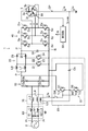
- FIG. 1 is an electric circuit diagram showing a configuration of a power converter according to an embodiment of the present invention.
- FIG. 2 is a diagram illustrating a refrigerant circuit of a refrigeration apparatus including a compressor connected to the power conversion apparatus.
- FIG. 3 is a characteristic diagram showing the magnitude of the leakage current with respect to the rotational speed of the compressor connected to the power converter.
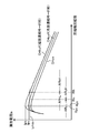
- FIG. 4 is a diagram showing how leakage current is controlled in the heating operation mode.
- FIG. 5 is a diagram showing how the leakage current is controlled in the cooling operation mode.
- FIG. 1 shows a configuration of a power conversion device (1) according to Embodiment 1 of the present invention.
- the power converter (1) is used to supply power to a compressor (not shown in FIG. 1) of the air conditioner (specifically, a motor (3) that drives the compressor).
- FIG. 2 shows a refrigerant circuit of an air conditioner, for example, provided with a compressor having the motor (3).
- the compressor (CM) incorporates the motor (3) and is disposed in the refrigerant circuit (90).
- the refrigerant circuit (90) includes a compressor (CM), a four-way switching valve (93), an air-cooled indoor heat exchanger (94) having an air-cooling fan (94a), and a valve body driven by a pulse motor. It has an electric expansion valve (95) with variable opening and an air-cooling outdoor heat exchanger (96) having an air-cooling fan (96a), and these devices are connected to a closed circuit in order by a refrigerant pipe (97), and a refrigeration cycle Is configured.
- CM compressor
- 93 four-way switching valve
- an air-cooled indoor heat exchanger (94) having an air-cooling fan (94a)
- a valve body driven by a pulse motor It has an electric expansion valve (95) with variable opening and an air-cooling outdoor heat exchanger (96) having an air-cooling fan (96a), and these devices are connected to a closed circuit in order by a refrigerant pipe (97), and a refrigeration cycle Is configured.
- the four-way switching valve (93) is switched as indicated by a solid line, whereby the refrigerant flows as indicated by a solid line arrow and the amount of heat absorbed by the outdoor heat exchanger (96) is converted into an indoor heat exchanger ( In 94), heat is radiated indoors, while in the cooling operation mode, the four-way switching valve (93) is switched as indicated by the broken line, whereby the refrigerant flows as indicated by the broken line arrow and the indoor heat exchanger (94) The amount of heat absorbed from the room is radiated to the outside air by the outdoor heat exchanger (96) to cool the room.
- the compressor (CM) houses a motor (3) as indicated by a broken line inside.
- Lubricating oil for lubricating the rotating part of the compressor (CM) and the like is supplied inside the compressor (CM).
- the lubricating oil circulates through the refrigerant circuit (90) together with the refrigerant and returns to the compressor (CM).
- the compressor (CM), the air cooling fan (94a) of the indoor heat exchanger (94), the electric expansion valve (95), and the air cooling fan (96a) of the outdoor heat exchanger (96) include a control unit ( 50) is connected, and this controller (50) allows the rotation speed of the motor (3) of the compressor (CM), the rotation speed of the air cooling fan (94a) of the indoor heat exchanger (94), and the electric expansion valve (95 ) And the number of rotations of the air cooling fan (96a) of the outdoor heat exchanger (96) are controlled.
- the power converter (1) includes a converter circuit (10), a power factor improving unit (20), a smoothing capacitor (30), an inverter circuit (40), a control unit (50), a line filter ( 60), a leakage current detection unit (70), and a compensation current output unit (80), convert AC power supplied from a single-phase AC power source (2) into AC power of a predetermined frequency and voltage, Supply to motor (3).
- a so-called IPM (Interior / Permanent / Magnet) motor is employed as the motor (3).
- the casing (3b) of this motor (3) is also used as the casing of the compressor (CM).
- the casing (3b) (that is, the compressor (CM)) is fixed in the casing of the outdoor heat exchanger (96) of the air conditioner. At this time, the casing (3b) of the motor (3) and the outdoor unit of the air conditioner are also electrically connected.
- a ground wire is connected to the casing of the outdoor heat exchanger (96) and grounded.
- the converter circuit (10) rectifies alternating current from the alternating current power supply (2) into direct current.
- the converter circuit (10) is a diode bridge circuit in which four diodes (10a to 10d) are connected in a bridge shape. With these diodes (10a to 10d), the AC voltage of the AC power source (2) is full-wave rectified and converted to a DC voltage.
- the power factor improving unit (20) is provided between the converter circuit (10) and the smoothing capacitor (30).
- the power factor improvement unit (20) of the present embodiment is a two-phase boost chopper circuit configured by a two-phase interleave method, including two reactors (L6, L7), two switching elements (21, 22), And four diodes (23, 24, 25, 26).
- the switching elements (21, 22) are turned on and off repeatedly at a predetermined duty ratio, thereby boosting the voltage, thereby turning on the diodes (10a to 10d) of the converter circuit (10). The angle increases and the power factor improves.
- the smoothing capacitor (30) smoothes the direct current boosted by the power factor correction unit (20).
- an electrolytic capacitor is used as the smoothing capacitor (30).
- ⁇ Inverter circuit> In the inverter circuit (40), the input node is connected to the smoothing capacitor (30), the supplied direct current is switched to convert it to three-phase alternating current (U, V, W), and the compressor ( CM) (specifically, motor (3)).
- the inverter circuit (40) of the present embodiment includes six switching elements (Su, Sv, Sw, Sx, Sy, Sz) connected in a bridge to output a three-phase alternating current to the motor (3). Yes. Specifically, the inverter circuit (40) includes three switching legs in which two switching elements are connected in series with each other, and the upper arm switching elements (Su, Sv, Sw) and the lower arm switching elements (Sx) in each switching leg. , Sy, Sz) are connected to coils (described later) of the respective phases of the motor (3). In addition, a free-wheeling diode (Du, Dv, Dw, Dx, Dy, Dz) is connected in reverse parallel to each switching element (Su, Sv, Sw, Sx, Sy, Sz).
- a free-wheeling diode Du, Dv, Dw, Dx, Dy, Dz
- the inverter circuit (40) switches the supplied direct current to a three-phase alternating current voltage by the switching operation of these switching elements (Su, Sv, Sw, Sx, Sy, Sz) to the motor (3). Supply. This switching operation is controlled by the control unit (50).
- the control unit (50) includes a microcomputer (not shown) and a memory device (which may be built in the microcomputer) that stores a program for operating the microcomputer.
- the control unit (50) outputs a control signal (G) to each switching element (Su, Sv, Sw, Sx, Sy, Sz) of the inverter circuit (40) to control the switching operation, so that the motor (3 ) To control.
- the control unit (50) uses dq axis vector control to control the motor (3).
- the line filter (60) includes two reactors (L1, L2) and two capacitors (61, 62).
- the reactors (L1, L2) are provided on an AC input line (Pl) that receives power from the AC power source (2).
- the capacitors (61, 62) are connected in series, and are connected between two AC input lines (Pl).
- the middle point (M1) of the two capacitors (61, 62) is connected to the ground via an earth wire.
- the leakage current detection unit (70) detects a detection current (Ib) that correlates with the leakage current (Ia) (detailed later) from the motor (3).
- the leakage current detector (70) includes a pair of common mode choke coils (L3, L4) and a detection coil (L5).
- the common mode choke coils (L3, L4) are provided on the AC input line (Pl) between the line filter (60) and the converter circuit (10).
- the detection coil (L5) is inductively coupled to the common mode choke coils (L3, L4).
- a detection current (Ib) corresponding to the difference in current between the AC input lines (Pl) flows through the detection coil (L5). This difference varies depending on the leakage current (Ia), and the detection current (Ib) correlates with the leakage current (Ia).
- the compensation current output unit (80) uses a push-pull circuit (81), which will be described in detail later, to provide a compensation current (Ic) for canceling the leakage current (Ia) and a current path (CP) (described later) ). Specifically, the compensation current output unit (80) amplifies the detection current (Ib) by the push-pull circuit (81) and superimposes it on the leakage current (Ia).
- the push-pull circuit (81) includes two transistors (Tr1, Tr2), two diodes (D1, D2), and a coupling capacitor (Cb).
- the coupling capacitor (Cb) is for cutting off direct current, and as an example, a 4700 pF capacitor was used.
- the transistor (Tr1) is an NPN type transistor, and the transistor (Tr2) is a PNP type transistor.
- the transistor (Tr1) and the transistor (Tr2) are connected in series. Specifically, the controlled terminal on the current outflow side of the transistor (Tr1) and the controlled terminal on the current inflow side of the transistor (Tr2) are connected to each other.
- the middle point (M2) of these transistors (Tr1, Tr2) is connected to the current path (CP) of the leakage current (Ia) through the coupling capacitor (Cb) as will be described in detail later.
- the diode (D1) is connected in reverse parallel to the transistor (Tr1), and the diode (D2) is connected in reverse parallel to the transistor (Tr2).
- a reverse bias voltage may act on the transistor (Tr1) or the transistor (Tr2), and if the voltage exceeds the breakdown voltage of the transistor (Tr1, Tr2), the transistor (Tr1, Tr2) is damaged. Therefore, these transistors (Tr1, Tr2) are protected from overvoltage by these diodes (D1, D2).
- the controlled terminal on the current inflow side of the transistor (Tr1) is the positive output of the converter circuit (10). Specifically, the positive DC bus (P) between the converter circuit (10) and the inverter circuit (40) It is connected to the.
- the controlled terminal on the current outflow side of the transistor (Tr2) is the negative output of the converter circuit (10), more specifically, the negative DC bus (N) between the converter circuit (10) and the inverter circuit (40). It is connected to the.
- the push-pull circuit (81) can output a compensation current (Ic) having a magnitude correlated with the leakage current (Ia). Note that the polarity of the detection current (Ib) is set so that the compensation current (Ic) has a phase opposite to that of the leakage current (Ia).
- a stray capacitance (3c) is formed between the coil (3a) and its casing (3b) (see FIG. 1). Therefore, if the voltage fluctuation (dv / dt) occurs in the coil (3a) of the motor (3) due to the switching of the inverter circuit (40), the leakage current (Ia) is generated from the casing (3b) of the motor (3). leak.
- the leakage current (Ia) is measured by the casing (3b) of the motor (3) (in this example, the casing of the compressor (CM)), the casing of the outdoor heat exchanger (96), and the outdoor heat exchanger (96).
- the ground wire flows to the ground as a current path (CP).
- the output (coupling capacitor (Cb)) of the compensation current output unit (80) is connected to the casing (3b) of the motor (3) as an example.
- this connection point is an example, and other parts on the current path (CP) can also be selected.
- the compensation current output unit (80) is provided with a switch (SW) for switching operation / stop of the compensation current output unit (80).
- the switch (SW) is a wiring path that supplies the detection current (Ib) detected by the detection coil (L5) of the leakage current detection unit (70) to the control terminals of the two transistors (Tr1, Tr2). Be placed. Accordingly, when the switch (SW) is opened, the push-pull circuit (81) is turned off, and the generation and output of the compensation current (Ic) are stopped.
- the switch (SW) is opened / closed by the control unit (50).
- the control unit (50) stores a characteristic diagram of the compressor (CM) measured in advance shown in FIG.
- the horizontal axis represents the rotational speed of the compressor (CM) (that is, the rotational speed of the motor (3)), and the vertical axis represents the leakage current (Ia) leaking from the compressor (CM).
- the leakage current characteristics when the compensation current output unit (80) is stopped that is, when no compensation current is supplied, are drawn in two ways: in the cooling operation mode and in the heating operation mode. It is. In both operation modes (CHhoff) and (CHcoff), after starting the compressor (CM), the leakage current increases initially as the speed increases from a low speed, but then the speed increases. Thus, the leakage current gradually decreases.
- the characteristic in the cooling operation mode (CHcoff) is higher than the characteristic in the heating operation mode (CHhoff). It is small. The reason is that in the cooling operation mode, the amount of lubricating oil accumulated in the indoor heat exchanger (94) is larger than in the heating operation mode, and the amount of lubricating oil in the compressor (CM) is small. Therefore, the impedance of the compressor (CM) is higher than that in the heating operation mode.
- the number of revolutions at the peak value (Iph) of the leakage current is the number of revolutions (Rph), which is lower than the peak value (Iph).
- the set rotational speed corresponding to the limit value (Lmax) standardized by IEC is the rotational speed (Rlh).
- the rotation speed at the peak value (Ipc) of the leakage current is the rotation speed (Rpc)
- the set rotation speed corresponding to the limit value (Lmax) is the rotation speed (Rlc)
- the heating operation mode characteristic (CHcoff) is set in the rotation speed (Rlh). ) (Rlc ⁇ Rlh).
- the leakage current is smaller than the two leakage current characteristics (CHhoff) and (CHcoff) when the compensation current output unit (80) is stopped in the entire rotation speed range, and the peak The value is lower than the limit value (Lmax).
- the control unit (50) receives a rotational speed signal of a rotational speed sensor (55) for detecting the rotational speed of the compressor (CM) (motor (3)),
- the switch (SW) of the compensation current output unit (80) is controlled to open and close based on the rotational speed. Specifically, the control unit (50) starts up the compressor (CM) until the rotation speed reaches a set rotation speed (Rlh, Rlc) corresponding to the limit value (Lmax), that is, the heating operation mode.
- a leakage current (Ia) flows from the motor (3) of the compressor (CM).
- the leakage current (Ia) flows, the difference in current between the AC input lines (Pl) fluctuates, and a voltage corresponding to the difference is generated in the detection coil (L5) of the leakage current detector (70).
- the leakage current detection unit (70) outputs the detection current (Ib) to the compensation current output unit (80) when the switch (SW) of the compensation current output unit (80) is closed.
- the detection current (Ib) is input to the control terminals of both transistors (Tr1, Tr2) when the switch (SW) is closed. Then, one of the transistors (Tr1, Tr2) performs an amplification operation according to the polarity of the detection current (Ib), and the compensation current (Ic) is output to the current path (CP).
- This compensation current (Ic) is in a phase opposite to the leakage current (Ia).
- the compressor (CM) rotation speed corresponds to the limit value (Lmax) in Fig. 3 (rotation speed (Rlh) in heating operation mode, rotation in cooling operation mode)
- the control unit (50) closes the switch (SW) of the compensation current output unit (80). Therefore, as described above, the detection current (Ib) from the leakage current detection unit (70) flows to the compensation current output unit (80), and the compensation current (Ic) is supplied to the current path (CP). (Ia) decreases.
- the compensation current output unit (80) operates in the rotation speed range (ARhL) less than the set rotation speed (Rlh) corresponding to the limit value (Lmax). However, the compensation current (Ic) flows, and the leakage current (Ia) becomes less than the limit value (Lmax). Then, after reaching the set rotational speed (Rlh), the compensation current output unit (80) stops, and the leakage current (Ia) increases to the limit value (Lmax) and then gradually decreases.
- the compensation current output unit (80) Operates, the compensation current (Ic) flows, and the leakage current (Ia) becomes less than the limit value (Lmax). Then, after reaching the set rotational speed (Rlc), the compensation current output unit (80) stops, and the leakage current (Ia) rises to the limit value (Lmax) and then gradually decreases.
- the operation / stop of the compensation current output unit (80) is switched and controlled according to the rotation speed of the compressor (CM), and the compensation current (Ic) is adjusted as necessary. Since the supply can be stopped, the power loss can be reduced as compared with the case where the compensation current is always supplied as in the prior art.
- the compressor speed (Rlh) and (Rlc) corresponding to the limit value (Lmax) specified by the Electrical Appliance and Material Safety Law and IEC are measured in advance, and after the compressor (CM) is started, Since the compensation current output section (80) was stopped after the engine speed exceeded the set speed (Rlh) and (Rlc) corresponding to the above limit value (Lmax), the legal regulation of the magnitude of the leakage current (Ia) It is possible to effectively suppress an increase in power loss while satisfying
- the configuration of the converter circuit (10) of the above embodiment is an example, and various other rectifier circuits such as a bridgeless converter circuit can be employed.
- the configuration of the inverter circuit (40) is also an example, and various circuits can be employed.
- various other configurations can be adopted for the configuration of the leakage current detection unit (70) and the compensation current output unit (80), and the position of the switch (SW) provided in the compensation current output unit (80) is It may be on the coupling capacitor (Cb) side.
- the power factor improvement unit (20) of the above embodiment is not essential, and a three-phase AC power source may be adopted as the AC power source (2).
- the refrigerant circuit of the air conditioner is an exemplification, and various other configurations can be adopted, and the refrigeration apparatus is not limited to the air conditioner.
- the present invention is useful as a power converter for driving a compressor.
Landscapes
- Engineering & Computer Science (AREA)
- Mechanical Engineering (AREA)
- General Engineering & Computer Science (AREA)
- Power Engineering (AREA)
- Physics & Mathematics (AREA)
- Thermal Sciences (AREA)
- Electromagnetism (AREA)
- Combustion & Propulsion (AREA)
- Chemical & Material Sciences (AREA)
- Inverter Devices (AREA)
- Control Of Ac Motors In General (AREA)
- Air Conditioning Control Device (AREA)
- Power Conversion In General (AREA)
- Control Of Motors That Do Not Use Commutators (AREA)
- Mathematical Physics (AREA)
- General Physics & Mathematics (AREA)
- Theoretical Computer Science (AREA)
- Software Systems (AREA)
- Computer Hardware Design (AREA)
Abstract
【課題】圧縮機を負荷とする電力変換装置において、漏洩電流(Ia)を補償する補償電流(Ic)を流す補償電流出力部(80)を設ける。制御部(50)は、圧縮機(CM)の回転数を検出する回転数センサ(55)の検出信号を受け、その回転数が、上記補償電流出力部(80)が動作していない状態で上記漏洩電流(Ia)がその制限値(例えば電気用品安全法やIECで規格された制限値)(Lmax)以下となる設定回転数に上昇したとき、補償電流出力部(80)を動作から停止に切り換える。従って、圧縮機からの漏洩電流を少ない電力損失で低減できる。
Description
この発明は負荷からの漏洩電流を低減する技術に関する。
一般に、電力変換装置の負荷が例えば電動機などの場合には、その電動機とグランドとの間に存在する静電容量によって電力変換装置内のパルス電圧の出力に伴い電動機から静電容量を経てグランドに漏洩電流が流れる。この漏洩電流を低減するように、従来、例えば特許文献1では、漏洩電流検出器で検出した漏洩電流に対応した交流波形の検出電流、又はこの検出電流に比例したモニタ電流が流れるコイルの両端電圧の瞬時値やピーク値の大きさが所定の閾値を超えるときに限り、上記漏洩電流を補償する補償電流を流す構成を採用している。
また、上記特許文献1では、電力変換装置に設けた力率改善回路のON状態(具体的には、内蔵するスイッチング素子のON/OFFのデューティ制御状態)では補償電流を流し、OFF状態(内蔵するスイッチング素子のOFF継続状態)では補償電流の供給を停止して、漏洩電流の大きい状態でのみ補償電流を流して、電力損失を低減する構成を採用している。
上記電力変換装置において、負荷として冷凍装置の冷媒回路に配置される圧縮機が接続される場合には、運転中の圧縮機からの漏洩電流を発明者等が実測したところ、回転数が上昇すると、圧縮機内の潤滑油が圧縮機内部から冷凍装置の冷媒配管や熱交換器に多く供給されて、圧縮機自体のインピーダンスが増加するため、漏洩電流は減少する特性がある。
従って、上記の圧縮機の漏洩電流の特性から、圧縮機の起動後、その回転数が低回転数から上昇して、漏洩電流が電気用品安全法やIEC(国際電気標準規格)で定められる制限値以下となる圧縮機の回転数域では、漏洩電流をあえて低減する必要はなく、補償電流を流す必要はない。
しかしながら、上記特許文献1に記載の発明では、漏洩電流に対応した検出電流やコイルの両端電圧に基づく制御、及び力率改善回路のON/OFF状態に基づく制御は、何れも、漏洩電流が上記法規制上の制限値以下の運転状態であっても、補償電流を流すため、電力損失が増大している欠点があることが判った。
特に、力率改善回路のON/OFF状態に基づく制御では、力率改善回路が電源高調波を抑制しようとON動作した状態では、漏洩電流は増大するものの、この状態であっても上記法規制上の制限値以下の状態も存在するため、電力損失が増大している。
また、上記漏洩電流に対応した検出電流やコイルの両端電圧に基づく制御では、これ等の制御によって補償電流が供給されると、これにより漏洩電流が減少するため、ハンチング防止のために制御のヒステリシスを大きく設定する必要が生じる。しかし、ヒステリシスを大きく設定し過ぎると、補償電流が必要以上に流れるため、電力損失が増大し、APF(Annual Performance Factor、通年エネルギー消費効率)が悪化する。
更に、補償電流を流す回路(漏洩電流キャンセラー回路)が動作すると、その回路のスイッチング動作に起因して外部へのEMI(Electro Magnetic Interference)ノイズ(電磁波ノイズ)が増大するため、そのEMI規格対応のためのコストが増大する欠点があった。特に、圧縮機の高回転域では、扱う電力量が増大しているため、電力変換装置に備えるコンバータ回路やインバータ回路のスイッチングノイズも増大して、EMIノイズが増大する。従って、この高回転域では、漏洩電流キャンセラー回路、コンバータ回路及びインバータ回路の三機器のスイッチングノイズが同時発生するため、これ等を総合した全EMIノイズを規格値内に収めるためのコストが極めて増大する欠点があった。
本発明はかかる課題を解決するものであり、その目的は、圧縮機を負荷とする電力変換装置において、漏洩電流が電気用品安全法やIECで定める制限値以下となる運転域では、補償電流の供給を停止できる構成を採用して、電力損失を軽減すると共に、APFの向上を図ることにある。
本発明の電力変換装置は、交流を直流に変換するコンバータ回路(10)と、上記コンバータ回路(10)に接続され、上記変換された直流を交流に変換するインバータ回路(40)とを備え、上記インバータ回路(40)により変換した交流を圧縮機(CM)に供給する電力変換装置において、上記圧縮機(CM)から漏洩する漏洩電流(Ia)の電流経路に上記漏洩電流(Ia)を補償する補償電流(Ic)を出力する補償電流出力部(80)と、上記圧縮機(CM)の回転数に応じて上記補償電流出力部(80)の動作と停止とを切り換える制御部(50)とを備えたことを特徴とする。
本発明は、圧縮機の回転数に応じて補償電流出力部の動作/停止が切換制御される。圧縮機からの漏洩電流は、圧縮機の回転数に応じて大小変化するので、漏洩電流の大きさに応じて補償電流の供給及び停止を制御することが可能である。
本発明は、上記電力変換装置において、上記制御部(50)は、上記圧縮機(CM)の回転数が、上記補償電流出力部(80)が動作していない状態で上記漏洩電流(Ia)が所定の制限値(Lmax)以下となる設定回転数(Rlh,Rlc)に上昇したとき、上記補償電流出力部(80)を動作から停止に切り換えることを特徴とする。
本発明では、圧縮機の起動後、圧縮機からの漏洩電流が所定の制限値(例えば電気用品安全法やIEC上の制限値)以下となる設定回転数で補償電流出力部を動作から停止に切り換えるので、法規制を満たしつつ、電力損失を軽減できる。
本発明は、上記電力変換装置において、上記圧縮機(CM)は、冷房運転モードと暖房運転モードを有する冷媒回路(90)に配置され、上記制御部(50)は、上記冷房運転モード時と暖房運転モード時とで上記設定回転数(Rlh,Rlc)を変更することを特徴とする。
本発明では、冷房運転モード時と暖房運転モード時とで漏洩電流が所定の制限値以下となる設定回転数が変更される。従って、冷房運転時と暖房運転時とで圧縮機回転数に応じた漏洩電流の大きさが異なっても、運転モードに拘わらず、法規制を満たしつつ電力損失を軽減できる。
本発明によれば、圧縮機の回転数に応じて補償電流の供給及び停止を制御したので、従来のように圧縮機の運転時に常に補償電流を供給する場合に比して、電力損失を軽減できると共に、APFの向上を図ることができる。
また、本発明によれば、漏洩電流が例えば法規制上の制限値以下となる圧縮機の回転数で補償電流の供給を停止できるので、法規制を満たしつつ、電力損失を軽減できる。
更に、本発明によれば、運転モードに拘わらず、法規制を満たしつつ、電力損失を軽減できる。
以下、本発明の実施形態について図面を参照しながら説明する。なお、以下の実施形態は、本質的に好ましい例示であって、本発明、その適用物、あるいはその用途の範囲を制限することを意図するものではない。
《発明の実施形態1》
図1は、本発明の実施形態1に係る電力変換装置(1)の構成を示す。この例では電力変換装置(1)は、空気調和装置の圧縮機(図1では省略)(詳しくは圧縮機を駆動するモータ(3))に電力を供給するために用いる。
図1は、本発明の実施形態1に係る電力変換装置(1)の構成を示す。この例では電力変換装置(1)は、空気調和装置の圧縮機(図1では省略)(詳しくは圧縮機を駆動するモータ(3))に電力を供給するために用いる。
上記モータ(3)を有する圧縮機が備えられる例えば空気調和装置の冷媒回路を図2に示す。同図において、圧縮機(CM)は上記モータ(3)を内蔵すると共に、冷媒回路(90)に配置される。
上記冷媒回路(90)は、圧縮機(CM)と、四路切換弁(93)と、空冷ファン(94a)を有する空冷室内熱交換器(94)と、弁体がパルスモータによって駆動される開度可変な電動膨張弁(95)と、空冷ファン(96a)を有する空冷室外熱交換器(96)とを備え、これ等機器が冷媒配管(97)により順に閉回路に接続して冷凍サイクルを構成している。そして、暖房運転モード時には、上記四路切換弁(93)を実線の如く切り換えることにより、冷媒を実線矢印のように流して、室外熱交換器(96)で吸熱した熱量を室内熱交換器(94)で室内に放熱して暖房する一方、冷房運転モード時には、上記四路切換弁(93)を破線の如く切り換えることにより、冷媒を破線矢印のように流して、室内熱交換器(94)で室内から吸熱した熱量を室外熱交換器(96)で外気に放熱して室内を冷房する。
上記圧縮機(CM)は、内部に破線で示すようにモータ(3)が収容される。圧縮機(CM)の内部には、圧縮機(CM)の回転部分等を潤滑する潤滑油が供給されている。圧縮機(CM)の運転時、この潤滑油は冷媒と共に冷媒回路(90)を循環して圧縮機(CM)に戻る。
そして、上記圧縮機(CM)、室内熱交換器(94)の空冷ファン(94a)、電動膨張弁(95)、及び室外熱交換器(96)の空冷ファン(96a)には、制御部(50)が接続され、この制御部(50)により,圧縮機(CM)のモータ(3)の回転数、室内熱交換器(94)の空冷ファン(94a) の回転数、電動膨張弁(95)の開度、及び室外熱交換器(96)の空冷ファン(96a)の回転数が制御される。
図1に示すように、電力変換装置(1)は、コンバータ回路(10)、力率改善部(20)、平滑コンデンサ(30)、インバータ回路(40)、制御部(50)、ラインフィルタ(60)、漏洩電流検出部(70)、及び補償電流出力部(80)を備え、単相の交流電源(2)から供給された交流電力を所定の周波数、電圧の交流電力に変換して、モータ(3)に供給する。モータ(3)には、例えば、いわゆるIPM(Interior Permanent Magnet)モータを採用する。
このモータ(3)のケーシング(3b)は、圧縮機(CM)のケーシングが兼用されている。ケーシング(3b)(すなわち圧縮機(CM))は、空気調和装置の室外熱交換器(96)のケーシング内に固定される。このとき、モータ(3)のケーシング(3b)と空気調和装置の室外機とは電気的にも接続される。そして、室外熱交換器(96)のケーシングにはアース線が接続されて接地される。
〈コンバータ回路〉
コンバータ回路(10)は、交流電源(2)からの交流を直流に整流する。本実施形態では、コンバータ回路(10)は、4つのダイオード(10a~10d)がブリッジ状に結線されたダイオードブリッジ回路である。これらのダイオード(10a~10d)によって、交流電源(2)の交流電圧を全波整流して、直流電圧に変換する。
コンバータ回路(10)は、交流電源(2)からの交流を直流に整流する。本実施形態では、コンバータ回路(10)は、4つのダイオード(10a~10d)がブリッジ状に結線されたダイオードブリッジ回路である。これらのダイオード(10a~10d)によって、交流電源(2)の交流電圧を全波整流して、直流電圧に変換する。
〈力率改善部〉
力率改善部(20)は、図1に示すように、コンバータ回路(10)と平滑コンデンサ(30)の間に設けられている。本実施形態の力率改善部(20)は、2相のインターリーブ方式で構成された2相の昇圧チョッパ回路であり、2つのリアクタ(L6,L7)、2つのスイッチング素子(21,22)、及び4つのダイオード(23,24,25,26)を備えている。力率改善部(20)では、スイッチング素子(21,22)のオンとオフを所定のデューティー比で繰り返すことで昇圧が行われ、それによりコンバータ回路(10)のダイオード(10a~10d)の導通角が増大して、力率が改善する。
力率改善部(20)は、図1に示すように、コンバータ回路(10)と平滑コンデンサ(30)の間に設けられている。本実施形態の力率改善部(20)は、2相のインターリーブ方式で構成された2相の昇圧チョッパ回路であり、2つのリアクタ(L6,L7)、2つのスイッチング素子(21,22)、及び4つのダイオード(23,24,25,26)を備えている。力率改善部(20)では、スイッチング素子(21,22)のオンとオフを所定のデューティー比で繰り返すことで昇圧が行われ、それによりコンバータ回路(10)のダイオード(10a~10d)の導通角が増大して、力率が改善する。
〈コンデンサ〉
平滑コンデンサ(30)は、力率改善部(20)によって昇圧された直流を平滑化する。この例では、平滑コンデンサ(30)には電解コンデンサを採用している。
平滑コンデンサ(30)は、力率改善部(20)によって昇圧された直流を平滑化する。この例では、平滑コンデンサ(30)には電解コンデンサを採用している。
〈インバータ回路〉
インバータ回路(40)は、入力ノードが平滑コンデンサ(30)に接続され、供給された直流をスイッチングして三相交流(U,V,W)に変換し、接続された負荷としての圧縮機(CM)(詳しくは、モータ(3))に供給する。
インバータ回路(40)は、入力ノードが平滑コンデンサ(30)に接続され、供給された直流をスイッチングして三相交流(U,V,W)に変換し、接続された負荷としての圧縮機(CM)(詳しくは、モータ(3))に供給する。
本実施形態のインバータ回路(40)は、三相交流をモータ(3)に出力するために、ブリッジ結線された6個のスイッチング素子(Su,Sv,Sw,Sx,Sy,Sz)を備えている。詳しくは、インバータ回路(40)は、2つのスイッチング素子を互いに直列接続した3つのスイッチングレグを備え、各スイッチングレグにおける上アームのスイッチング素子(Su,Sv,Sw)と下アームのスイッチング素子(Sx,Sy,Sz)との中点が、それぞれモータ(3)の各相のコイル(後述)に接続されている。また、各スイッチング素子(Su,Sv,Sw,Sx,Sy,Sz)には、還流ダイオード(Du,Dv,Dw,Dx,Dy,Dz)が逆並列接続されている。
インバータ回路(40)は、これらのスイッチング素子(Su,Sv,Sw,Sx,Sy,Sz)のスイッチング動作によって、供給された直流をスイッチングして三相交流電圧に変換し、モータ(3)へ供給する。このスイッチング動作の制御は制御部(50)が行う。
〈制御部〉
制御部(50)は、マイクロコンピュータ(図示は省略)とそれを動作させるプログラムを格納したメモリデバイス(マイクロコンピュータに内蔵してもよい)を有している。制御部(50)は、インバータ回路(40)の各スイッチング素子(Su,Sv,Sw,Sx,Sy,Sz)に制御信号(G)を出力してスイッチング動作を制御することによって、モータ(3)を制御する。この例では、制御部(50)は、モータ(3)の制御にd-q軸ベクトル制御を用いる。
制御部(50)は、マイクロコンピュータ(図示は省略)とそれを動作させるプログラムを格納したメモリデバイス(マイクロコンピュータに内蔵してもよい)を有している。制御部(50)は、インバータ回路(40)の各スイッチング素子(Su,Sv,Sw,Sx,Sy,Sz)に制御信号(G)を出力してスイッチング動作を制御することによって、モータ(3)を制御する。この例では、制御部(50)は、モータ(3)の制御にd-q軸ベクトル制御を用いる。
〈ラインフィルタ〉
ラインフィルタ(60)は、2つのリアクタ(L1,L2)と、2つのコンデンサ(61,62)を備えている。リアクタ(L1,L2)は、交流電源(2)の電力を受ける交流入力線(Pl)上に設けられている。また、コンデンサ(61,62)同士は直列接続され、2つの交流入力線(Pl)間に接続されている。2つのコンデンサ(61,62)の中点(M1)は、アース線を介して、グランドに接続されている。
ラインフィルタ(60)は、2つのリアクタ(L1,L2)と、2つのコンデンサ(61,62)を備えている。リアクタ(L1,L2)は、交流電源(2)の電力を受ける交流入力線(Pl)上に設けられている。また、コンデンサ(61,62)同士は直列接続され、2つの交流入力線(Pl)間に接続されている。2つのコンデンサ(61,62)の中点(M1)は、アース線を介して、グランドに接続されている。
〈漏洩電流検出部〉
漏洩電流検出部(70)は、モータ(3)からの漏洩電流(Ia)(後に詳述)に相関する検出電流(Ib)を検出する。この例では、図1に示すように、漏洩電流検出部(70)は、1対のコモンモードチョークコイル(L3,L4)、及び検出コイル(L5)を備えている。コモンモードチョークコイル(L3,L4)は、ラインフィルタ(60)とコンバータ回路(10)の間の交流入力線(Pl)上に設けられている。また、検出コイル(L5)は、コモンモードチョークコイル(L3,L4)に誘導結合されている。それにより、検出コイル(L5)には、交流入力線(Pl)間の電流の差分に応じた検出電流(Ib)が流れることになる。この差分は漏洩電流(Ia)によって変動し、検出電流(Ib)は漏洩電流(Ia)に相関する。
漏洩電流検出部(70)は、モータ(3)からの漏洩電流(Ia)(後に詳述)に相関する検出電流(Ib)を検出する。この例では、図1に示すように、漏洩電流検出部(70)は、1対のコモンモードチョークコイル(L3,L4)、及び検出コイル(L5)を備えている。コモンモードチョークコイル(L3,L4)は、ラインフィルタ(60)とコンバータ回路(10)の間の交流入力線(Pl)上に設けられている。また、検出コイル(L5)は、コモンモードチョークコイル(L3,L4)に誘導結合されている。それにより、検出コイル(L5)には、交流入力線(Pl)間の電流の差分に応じた検出電流(Ib)が流れることになる。この差分は漏洩電流(Ia)によって変動し、検出電流(Ib)は漏洩電流(Ia)に相関する。
〈補償電流出力部〉
補償電流出力部(80)は、後に詳述するプッシュプル回路(81)によって、漏洩電流(Ia)を打ち消すための補償電流(Ic)を、漏洩電流(Ia)の電流経路(CP)(後述)に供給する。具体的には、補償電流出力部(80)は、検出電流(Ib)をプッシュプル回路(81)によって増幅し、それを漏洩電流(Ia)に重畳する。
補償電流出力部(80)は、後に詳述するプッシュプル回路(81)によって、漏洩電流(Ia)を打ち消すための補償電流(Ic)を、漏洩電流(Ia)の電流経路(CP)(後述)に供給する。具体的には、補償電流出力部(80)は、検出電流(Ib)をプッシュプル回路(81)によって増幅し、それを漏洩電流(Ia)に重畳する。
プッシュプル回路(81)は、図1に示すように、2つのトランジスタ(Tr1,Tr2)、2つのダイオード(D1,D2)、及びカップリングコンデンサ(Cb)を備えている。カップリングコンデンサ(Cb)は直流を遮断するためのものであり、一例として、4700pFのコンデンサを用いた。
トランジスタ(Tr1)はNPN型のトランジスタであり、トランジスタ(Tr2)はPNP型のトランジスタである。そして、トランジスタ(Tr1)とトランジスタ(Tr2)とは直列接続されている。具体的には、トランジスタ(Tr1)の電流流出側の被制御端子と、トランジスタ(Tr2)の電流流入側の被制御端子とが、互いに接続されている。これらのトランジスタ(Tr1,Tr2)の中点(M2)は、カップリングコンデンサ(Cb)を介して、後に詳述するように、漏洩電流(Ia)の電流経路(CP)に接続されている。
また、トランジスタ(Tr1)には、ダイオード(D1)が逆並列接続され、トランジスタ(Tr2)には、ダイオード(D2)が逆並列接続されている。トランジスタ(Tr1)やトランジスタ(Tr2)には、逆バイアス電圧が作用する場合があり、その電圧がトランジスタ(Tr1,Tr2)の耐圧を超えると破損に到る。そこで、これらのダイオード(D1,D2)によって、各トランジスタ(Tr1,Tr2)を過電圧から保護している。
また、トランジスタ(Tr1)の電流流入側の被制御端子は、コンバータ回路(10)の正側出力、詳しくは、コンバータ回路(10)とインバータ回路(40)間の正側の直流母線(P)に接続されている。一方、トランジスタ(Tr2)の電流流出側の被制御端子は、コンバータ回路(10)の負側出力、詳しくは、コンバータ回路(10)とインバータ回路(40)間の負側の直流母線(N)に接続されている。
そして、両トランジスタ(Tr1,Tr2)の制御端子には、検出電流(Ib)が供給される。これにより、プッシュプル回路(81)では、漏洩電流(Ia)に相関した大きさの補償電流(Ic)を出力することができる。なお、検出電流(Ib)の極性は、補償電流(Ic)が漏洩電流(Ia)とは逆相となるように設定されている。
-補償電流出力部(80)の出力の接続-
モータ(3)では、コイル(3a)とそのケーシング(3b)との間には浮遊容量(3c)が形成されている(図1参照)。そのため、インバータ回路(40)のスイッチングにともなってモータ(3)のコイル(3a)に電圧変動(dv/dt)を生ずると、モータ(3)のケーシング(3b)からは漏洩電流(Ia)が流出する。そして、漏洩電流(Ia)は、モータ(3)のケーシング(3b)(この例では圧縮機(CM)のケーシング)、室外熱交換器(96)のケーシング、及び室外熱交換器(96)のアース線を電流経路(CP)としてグランドに流れる。
モータ(3)では、コイル(3a)とそのケーシング(3b)との間には浮遊容量(3c)が形成されている(図1参照)。そのため、インバータ回路(40)のスイッチングにともなってモータ(3)のコイル(3a)に電圧変動(dv/dt)を生ずると、モータ(3)のケーシング(3b)からは漏洩電流(Ia)が流出する。そして、漏洩電流(Ia)は、モータ(3)のケーシング(3b)(この例では圧縮機(CM)のケーシング)、室外熱交換器(96)のケーシング、及び室外熱交換器(96)のアース線を電流経路(CP)としてグランドに流れる。
そこで、本実施形態では、補償電流出力部(80)の出力(カップリングコンデンサ(Cb))は、一例として、モータ(3)のケーシング(3b)に接続してある。勿論、この接続点は例示であり、電流経路(CP)上の他の部位も選択可能である。
-補償電流出力部(80)の制御-
上記補償電流出力部(80)には、この補償電流出力部(80)の動作/停止を切り換えるために、スイッチ(SW)が配置される。スイッチ(SW)は、具体的には、漏洩電流検出部(70)の検出コイル(L5)で検出した検出電流(Ib)を2つのトランジスタ(Tr1,Tr2)の制御端子に供給する配線経路に配置される。従って、スイッチ(SW)の開動作時には、プッシュプル回路(81)がOFF動作して、補償電流(Ic)の生成、出力が停止する。
上記補償電流出力部(80)には、この補償電流出力部(80)の動作/停止を切り換えるために、スイッチ(SW)が配置される。スイッチ(SW)は、具体的には、漏洩電流検出部(70)の検出コイル(L5)で検出した検出電流(Ib)を2つのトランジスタ(Tr1,Tr2)の制御端子に供給する配線経路に配置される。従って、スイッチ(SW)の開動作時には、プッシュプル回路(81)がOFF動作して、補償電流(Ic)の生成、出力が停止する。
上記スイッチ(SW)は、上記制御部(50)により開/閉制御される。制御部(50)には、この制御を行うために、図3に示す予め測定した圧縮機(CM)の特性図が記憶されている。
上記特性図は、横軸に圧縮機(CM)の回転数(すなわち、モータ(3)の回転数)、縦軸に圧縮機(CM)から漏洩する漏洩電流(Ia)をとっている。この特性図では、上記補償電流出力部(80)の停止時、すなわち、補償電流の供給がない場合の漏洩電流特性が、空気調和装置の冷房運転モード時と暖房運転モード時との2通り描かれている。両運転モード時の特性(CHhoff)、(CHcoff)は、圧縮機(CM)の起動後、低回転数からの上昇に応じて当初は漏洩電流は増大するが、その後は回転数の上昇に応じて漏洩電流が漸次減少する特性である。このような特性の傾向は、圧縮機(CM)の回転数がある程度上昇すると、それに応じて圧縮機(CM)からの潤滑油の吐出量が増大して、モータ(3)のコイル(3a)が圧縮機(CM)内に溜まった潤滑油の上方に露出する部位が多くなるため、圧縮機(CM)のインピーダンスが増加して、漏洩電流が漸次減少するからである。
また、上記2つの特性(CHhoff)、(CHcoff)のうち、冷房運転モード時の特性(CHcoff)は、暖房運転モード時の特性(CHhoff)に比して、発生する漏洩電流は全回転数域で小さい。その理由は、冷房運転モード時では、暖房運転モード時に比べて室内熱交換器(94)内への潤滑油の溜まり込み量が多く、圧縮機(CM)内での潤滑油の油量が少ないため、圧縮機(CM)のインピーダンスが暖房運転モード時よりも高いからである。
そして、上記暖房運転モード時の特性(CHhoff)では、漏洩電流のピーク値(Iph)での回転数は回転数(Rph)であり、前記ピーク値(Iph)よりも低くて電気用品安全法やIECで規格された制限値(Lmax)に対応する設定回転数は、回転数(Rlh)である。一方、冷房運転モード時の特性(CHcoff)では、漏洩電流のピーク値(Ipc)での回転数は回転数(Rpc)であり、暖房運転モード時の特性(CHhoff)でのピーク回転数(Rph)よりも低い(Rpc<Rph)。また、冷房運転モード時の特性(CHcoff)において、上記制限値(Lmax)に対応する設定回転数は回転数(Rlc)であり、暖房運転モード時の特性(CHcoff)での設定回転数(Rlh)よりも低い(Rlc<Rlh)。図3では、補償電流出力部(80)の停止状態での上記2つの漏洩電流特性(CHhoff)、(CHcoff)と共に、補償電流出力部(80)の動作時、すなわち、補償電流を流した場合の漏洩電流特性(CHon)を描いている。この漏洩電流特性(CHon)では、全回転数域で、上記補償電流出力部(80)の停止状態での2つの漏洩電流特性(CHhoff)、(CHcoff)よりも漏洩電流は小さいし、そのピーク値は上記制限値(Lmax)よりも低い。
そして、上記制御部(50)は、図1に示したように、上記圧縮機(CM)(モータ(3))の回転数を検出する回転数センサ(55)の回転数信号を受け、この回転数に基づいて上記補償電流出力部(80)のスイッチ(SW)を開閉制御する。具体的に、制御部(50)は、圧縮機(CM)の起動後、その回転数が上記制限値(Lmax)に対応する設定回転数(Rlh,Rlc)になるまで、すなわち、暖房運転モード時では特性(CHcoff)の設定回転数(Rlh)未満の回転数域(ARhL)、冷房運転モード時では特性(CHcoff)の設定回転数(Rlc)未満の回転数域(ARcL)において、スイッチ(SW)を閉制御して、補償電流出力部(80)を動作させ、補償電流(Ic)を流す。一方、圧縮機(CM)の回転数が上記設定回転数(Rlh,Rlc)に達すると、スイッチ(SW)を開制御して、補償電流出力部(80)を停止させ、補償電流(Ic)の供給を停止させる。その後は、上記設定回転数(Rlh,Rlc)を越える回転数域(ARhH,ARcH)で上記補償電流出力部(80)の停止制御を継続する。
〈電力変換装置の動作〉
インバータ回路(40)がスイッチング動作を行うと、圧縮機(CM)のモータ(3)からは漏洩電流(Ia)が流れ出す。漏洩電流(Ia)が流れると、交流入力線(Pl)間の電流の差分が変動し、漏洩電流検出部(70)の検出コイル(L5)には、その差分に応じた電圧が生じる。漏洩電流検出部(70)は、補償電流出力部(80)のスイッチ(SW)が閉状態では、検出電流(Ib)を補償電流出力部(80)に出力する。
インバータ回路(40)がスイッチング動作を行うと、圧縮機(CM)のモータ(3)からは漏洩電流(Ia)が流れ出す。漏洩電流(Ia)が流れると、交流入力線(Pl)間の電流の差分が変動し、漏洩電流検出部(70)の検出コイル(L5)には、その差分に応じた電圧が生じる。漏洩電流検出部(70)は、補償電流出力部(80)のスイッチ(SW)が閉状態では、検出電流(Ib)を補償電流出力部(80)に出力する。
補償電流出力部(80)では、スイッチ(SW)の閉状態にて、検出電流(Ib)が両トランジスタ(Tr1,Tr2)の制御端子に入力される。そうすると、検出電流(Ib)の極性に応じて何れかのトランジスタ(Tr1,Tr2)が増幅動作を行い、補償電流(Ic)が電流経路(CP)に出力される。この補償電流(Ic)は漏洩電流(Ia)とは逆相の電流であり、トランジスタ(Tr1,Tr2)の増幅率や検出コイル(L5)の巻数などを適宜設定しておくことで、漏洩電流(Ia)を十分に低減できる大きさの電流となる。そのため、補償電流(Ic)が漏洩電流(Ia)と合流すると、アースに流れ込む電流(Io)(図1参照)が低減する。
-補償電流出力部(80)の動作-
圧縮機(CM)の起動後、圧縮機(CM)の回転数が図3の制限値(Lmax)に対応する設定回転数(暖房運転モード時では回転数(Rlh)、冷房運転モード時では回転数(Rlc))未満の領域(ARhL)、(ARcL)では、制御部(50)は補償電流出力部(80)のスイッチ(SW)を閉制御する。従って、補償電流出力部(80)には、上記の通り漏洩電流検出部(70)からの検出電流(Ib)が流れ、補償電流(Ic)が電流経路(CP)に供給されて、漏洩電流(Ia)が減少する。
圧縮機(CM)の起動後、圧縮機(CM)の回転数が図3の制限値(Lmax)に対応する設定回転数(暖房運転モード時では回転数(Rlh)、冷房運転モード時では回転数(Rlc))未満の領域(ARhL)、(ARcL)では、制御部(50)は補償電流出力部(80)のスイッチ(SW)を閉制御する。従って、補償電流出力部(80)には、上記の通り漏洩電流検出部(70)からの検出電流(Ib)が流れ、補償電流(Ic)が電流経路(CP)に供給されて、漏洩電流(Ia)が減少する。
そして、圧縮機(CM)の回転数が上記回転数域(ARhL)、(ARcL)から上昇し、制限値(Lmax)に対応する設定回転数(Rlh)、(Rlc)に達すると、制御部(50)が補償電流出力部(80)のスイッチ(SW)を開制御するので、補償電流出力部(80)は動作を停止し、補償電流(Ic)の供給は停止される。そして、その後、圧縮機(CM)の回転数の上昇に伴い設定回転数(Rlh)、(Rlc)以上の回転数域(ARhH)、(ARcH)に入ると、制御部(50)は補償電流出力部(80)のスイッチ(SW)の開制御を保持する。
従って、暖房運転モード時には、図4に破線で示したように、制限値(Lmax)に対応する設定回転数(Rlh)未満の回転数域(ARhL)では、補償電流出力部(80)が動作し、補償電流(Ic)が流れて、漏洩電流(Ia)は制限値(Lmax)未満となる。そして、設定回転数(Rlh)に達した後は、補償電流出力部(80)が停止して、漏洩電流(Ia)は制限値(Lmax)に上昇した後、徐々に低下する。
同様に、冷房運転モード時には、図5に一点鎖線で示したように、制限値(Lmax)に対応する設定回転数(Rlc)未満の回転数域(ARcL)では、補償電流出力部(80)が動作し、補償電流(Ic)が流れて、漏洩電流(Ia)は制限値(Lmax)未満となる。そして、設定回転数(Rlc)に達した後は、補償電流出力部(80)が停止して、漏洩電流(Ia)は制限値(Lmax)に上昇した後、徐々に低下する。
〈本実施形態の効果〉
以上のように、本実施形態によれば、圧縮機(CM)の回転数に応じて補償電流出力部(80)の動作/停止を切換制御して、必要に応じて補償電流(Ic)の供給を停止できるので、従来のように補償電流の供給を常に行う場合に比して、電力損失を軽減できる。
以上のように、本実施形態によれば、圧縮機(CM)の回転数に応じて補償電流出力部(80)の動作/停止を切換制御して、必要に応じて補償電流(Ic)の供給を停止できるので、従来のように補償電流の供給を常に行う場合に比して、電力損失を軽減できる。
特に、電気用品安全法やIECで規格された制限値(Lmax)に対応する圧縮機の回転数(Rlh)、(Rlc)を予め実測し、圧縮機(CM)の起動後、その回転数が上記制限値(Lmax)に対応する設定回転数(Rlh)、(Rlc)以上に上昇した後は、補償電流出力部(80)を停止させたので、漏洩電流(Ia)の大きさの法規制を満たしつつ、電力損失の増大を有効に抑制することが可能である。
また、暖房運転モード時と冷房運転モード時とで上記制限値(Lmax)に対応する設定回転数(Rlh,Rlc)を変更したので、冷媒回路(90)の暖房及び冷房の運転モードに拘わらず、法規制を満たしつつ電力損失を最大限低減することが可能である。
《その他の実施形態》
なお、上記実施形態のコンバータ回路(10)の構成は例示であり、他にブリッジレスコンバータ回路など、種々の整流回路を採用できる。また、インバータ回路(40)についても構成は例示であり、種々の回路を採用できる。同様に、漏洩電流検出部(70)や補償電流出力部(80)の構成についても他の種々の構成が採用可能であるし、補償電流出力部(80)に設けるスイッチ(SW)の位置はカップリングコンデンサ(Cb)側であっても良い。
なお、上記実施形態のコンバータ回路(10)の構成は例示であり、他にブリッジレスコンバータ回路など、種々の整流回路を採用できる。また、インバータ回路(40)についても構成は例示であり、種々の回路を採用できる。同様に、漏洩電流検出部(70)や補償電流出力部(80)の構成についても他の種々の構成が採用可能であるし、補償電流出力部(80)に設けるスイッチ(SW)の位置はカップリングコンデンサ(Cb)側であっても良い。
更に、上記実施形態の力率改善部(20)は必須ではないし、交流電源(2)には、三相の交流電源を採用してもよい。加えて、空気調和装置の冷媒回路は例示であり、他の種々の構成を採用可能であるし、空気調和装置に限らず冷凍装置であれば良い。
本発明は、圧縮機を駆動する電力変換装置として有用である。
1 電力変換装置
CM 圧縮機
3 モータ
10 コンバータ回路
40 インバータ回路
50 制御部
55 回転数センサ
70 漏洩電流検出部
80 補償電流出力部
SW スイッチ
CM 圧縮機
3 モータ
10 コンバータ回路
40 インバータ回路
50 制御部
55 回転数センサ
70 漏洩電流検出部
80 補償電流出力部
SW スイッチ
Claims (3)
- 交流を直流に変換するコンバータ回路(10)と、
上記コンバータ回路(10)に接続され、上記変換された直流を交流に変換するインバータ回路(40)とを備え、
上記インバータ回路(40)により変換した交流を圧縮機(CM)に供給する電力変換装置において、
上記圧縮機(CM)から漏洩する漏洩電流(Ia)の電流経路に上記漏洩電流(Ia)を補償する補償電流(Ic)を出力する補償電流出力部(80)と、
上記圧縮機(CM)の回転数に応じて上記補償電流出力部(80)の動作と停止とを切り換える制御部(50)と
を備えたことを特徴とする電力変換装置。 - 上記請求項1記載の電力変換装置において、
上記制御部(50)は、
上記圧縮機(CM)の回転数が、上記補償電流出力部(80)が動作していない状態で上記漏洩電流(Ia)が所定の制限値(Lmax)以下となる設定回転数(Rlh,Rlc)に上昇したとき、上記補償電流出力部(80)を動作から停止に切り換える
ことを特徴とする電力変換装置。 - 上記請求項2記載の電力変換装置において、
上記圧縮機(CM)は、冷房運転モードと暖房運転モードを有する冷媒回路(90)に配置され、
上記制御部(50)は、
上記冷房運転モード時と暖房運転モード時とで上記設定回転数(Rlh,Rlc)を変更する
ことを特徴とする電力変換装置。
Priority Applications (4)
| Application Number | Priority Date | Filing Date | Title |
|---|---|---|---|
| EP15844861.3A EP3176940B1 (en) | 2014-09-26 | 2015-08-05 | Power conversion device |
| CN201580051335.9A CN107078657B (zh) | 2014-09-26 | 2015-08-05 | 功率转换装置 |
| US15/511,289 US10003277B2 (en) | 2014-09-26 | 2015-08-05 | Power conversion device |
| ES15844861T ES2753251T3 (es) | 2014-09-26 | 2015-08-05 | Dispositivo de conversión de energía |
Applications Claiming Priority (2)
| Application Number | Priority Date | Filing Date | Title |
|---|---|---|---|
| JP2014197278A JP5850116B1 (ja) | 2014-09-26 | 2014-09-26 | 電力変換装置 |
| JP2014-197278 | 2014-09-26 |
Publications (1)
| Publication Number | Publication Date |
|---|---|
| WO2016047019A1 true WO2016047019A1 (ja) | 2016-03-31 |
Family
ID=55237933
Family Applications (1)
| Application Number | Title | Priority Date | Filing Date |
|---|---|---|---|
| PCT/JP2015/003944 Ceased WO2016047019A1 (ja) | 2014-09-26 | 2015-08-05 | 電力変換装置 |
Country Status (6)
| Country | Link |
|---|---|
| US (1) | US10003277B2 (ja) |
| EP (1) | EP3176940B1 (ja) |
| JP (1) | JP5850116B1 (ja) |
| CN (1) | CN107078657B (ja) |
| ES (1) | ES2753251T3 (ja) |
| WO (1) | WO2016047019A1 (ja) |
Cited By (2)
| Publication number | Priority date | Publication date | Assignee | Title |
|---|---|---|---|---|
| TWI619886B (zh) * | 2017-04-06 | 2018-04-01 | Matsushita Electric Taiwan Co Ltd | compressor |
| EP3351880A1 (de) * | 2016-11-14 | 2018-07-25 | Liebherr-Hausgeräte Ochsenhausen GmbH | Kühl- und/oder gefriergerät |
Families Citing this family (18)
| Publication number | Priority date | Publication date | Assignee | Title |
|---|---|---|---|---|
| US10284132B2 (en) | 2016-04-15 | 2019-05-07 | Emerson Climate Technologies, Inc. | Driver for high-frequency switching voltage converters |
| US10656026B2 (en) | 2016-04-15 | 2020-05-19 | Emerson Climate Technologies, Inc. | Temperature sensing circuit for transmitting data across isolation barrier |
| US9933842B2 (en) | 2016-04-15 | 2018-04-03 | Emerson Climate Technologies, Inc. | Microcontroller architecture for power factor correction converter |
| US10312798B2 (en) | 2016-04-15 | 2019-06-04 | Emerson Electric Co. | Power factor correction circuits and methods including partial power factor correction operation for boost and buck power converters |
| US10277115B2 (en) | 2016-04-15 | 2019-04-30 | Emerson Climate Technologies, Inc. | Filtering systems and methods for voltage control |
| US10305373B2 (en) | 2016-04-15 | 2019-05-28 | Emerson Climate Technologies, Inc. | Input reference signal generation systems and methods |
| US10763740B2 (en) | 2016-04-15 | 2020-09-01 | Emerson Climate Technologies, Inc. | Switch off time control systems and methods |
| JP6606123B2 (ja) * | 2017-05-30 | 2019-11-13 | ファナック株式会社 | 漏れ電流の発生を検知するモータ駆動装置 |
| JP6394741B1 (ja) | 2017-05-30 | 2018-09-26 | ダイキン工業株式会社 | 電力変換装置、冷凍装置 |
| KR102542941B1 (ko) * | 2018-06-08 | 2023-06-14 | 현대자동차주식회사 | 저주파 누설전류를 감소시킬 수 있는 충전 장치 |
| CN108471244B (zh) * | 2018-06-14 | 2025-04-08 | 珠海格力电器股份有限公司 | 一种变频压缩机降低泄漏电流的补偿电路及其控制方法 |
| JP2020065409A (ja) * | 2018-10-19 | 2020-04-23 | パナソニックIpマネジメント株式会社 | 漏洩電流低減回路 |
| US11277003B2 (en) * | 2020-01-09 | 2022-03-15 | Emerson Climate Technologies, Inc. | Multi-phase EMI and transient protection circuits and synchronous rectification control for compressors of refrigeration systems |
| US11912147B2 (en) * | 2020-02-21 | 2024-02-27 | The Trustees Of Columbia University In The City Of New York | Non-isolated DC fast charger for electrified vehicles |
| US11554633B2 (en) * | 2020-08-20 | 2023-01-17 | Thermo King Llc | Closed loop feedback control and diagnostics of a transport climate control system |
| GB2604188A (en) * | 2021-02-22 | 2022-08-31 | Edwards Tech Vacuum Engineering Qingdao Co Ltd | Control of liquid ring pump |
| JP7315862B2 (ja) * | 2021-09-30 | 2023-07-27 | ダイキン工業株式会社 | 電力変換装置及び冷凍装置 |
| CN114234362B (zh) * | 2021-12-27 | 2023-03-24 | 珠海格力电器股份有限公司 | 一种判断元器件老化的控制方法、装置及空调 |
Citations (3)
| Publication number | Priority date | Publication date | Assignee | Title |
|---|---|---|---|---|
| JP2002272132A (ja) * | 1995-12-21 | 2002-09-20 | Mitsubishi Electric Corp | 漏電防止装置、及びインバータ駆動負荷に対する漏電防止方法 |
| JP2004364344A (ja) * | 2003-06-02 | 2004-12-24 | Hitachi Home & Life Solutions Inc | 漏れ電流キャンセラ回路 |
| WO2013111403A1 (ja) * | 2012-01-27 | 2013-08-01 | ダイキン工業株式会社 | 電力変換回路 |
Family Cites Families (7)
| Publication number | Priority date | Publication date | Assignee | Title |
|---|---|---|---|---|
| JP3331881B2 (ja) | 1995-12-21 | 2002-10-07 | 三菱電機株式会社 | インバータ装置、圧縮機 |
| TW407394B (en) * | 1997-10-16 | 2000-10-01 | Toshiba Corp | Frequency converter to output electric driving power to motor and filter installed on it |
| US6134126A (en) * | 1998-09-08 | 2000-10-17 | Kabushiki Kaisha Toshiba | Power conversion system |
| EP1220432A3 (en) * | 2000-12-19 | 2003-01-29 | Fuji Electric Co., Ltd. | Noise reduction apparatus for electric power conversion apparatus |
| CN100406816C (zh) * | 2004-04-26 | 2008-07-30 | 大金工业株式会社 | 变频驱动压缩机的预热运转方法及其装置 |
| JP4581574B2 (ja) * | 2004-09-08 | 2010-11-17 | 株式会社ジェイテクト | モータ制御装置及び電動パワーステアリング装置 |
| EP2820754A4 (en) * | 2011-12-19 | 2016-07-20 | Zbb Energy Corp | SYSTEM AND METHOD FOR CONTROLLING A MULTI-PHASE ALTERNATING MACHINE AT LOW SPEED |
-
2014
- 2014-09-26 JP JP2014197278A patent/JP5850116B1/ja not_active Expired - Fee Related
-
2015
- 2015-08-05 CN CN201580051335.9A patent/CN107078657B/zh not_active Expired - Fee Related
- 2015-08-05 WO PCT/JP2015/003944 patent/WO2016047019A1/ja not_active Ceased
- 2015-08-05 EP EP15844861.3A patent/EP3176940B1/en not_active Not-in-force
- 2015-08-05 US US15/511,289 patent/US10003277B2/en not_active Expired - Fee Related
- 2015-08-05 ES ES15844861T patent/ES2753251T3/es active Active
Patent Citations (3)
| Publication number | Priority date | Publication date | Assignee | Title |
|---|---|---|---|---|
| JP2002272132A (ja) * | 1995-12-21 | 2002-09-20 | Mitsubishi Electric Corp | 漏電防止装置、及びインバータ駆動負荷に対する漏電防止方法 |
| JP2004364344A (ja) * | 2003-06-02 | 2004-12-24 | Hitachi Home & Life Solutions Inc | 漏れ電流キャンセラ回路 |
| WO2013111403A1 (ja) * | 2012-01-27 | 2013-08-01 | ダイキン工業株式会社 | 電力変換回路 |
Cited By (2)
| Publication number | Priority date | Publication date | Assignee | Title |
|---|---|---|---|---|
| EP3351880A1 (de) * | 2016-11-14 | 2018-07-25 | Liebherr-Hausgeräte Ochsenhausen GmbH | Kühl- und/oder gefriergerät |
| TWI619886B (zh) * | 2017-04-06 | 2018-04-01 | Matsushita Electric Taiwan Co Ltd | compressor |
Also Published As
| Publication number | Publication date |
|---|---|
| US20170288567A1 (en) | 2017-10-05 |
| CN107078657A (zh) | 2017-08-18 |
| US10003277B2 (en) | 2018-06-19 |
| EP3176940A4 (en) | 2018-04-11 |
| EP3176940B1 (en) | 2019-06-19 |
| ES2753251T3 (es) | 2020-04-07 |
| EP3176940A1 (en) | 2017-06-07 |
| JP5850116B1 (ja) | 2016-02-03 |
| JP2016073025A (ja) | 2016-05-09 |
| CN107078657B (zh) | 2019-08-20 |
Similar Documents
| Publication | Publication Date | Title |
|---|---|---|
| JP5850116B1 (ja) | 電力変換装置 | |
| US11716040B2 (en) | Hybrid drive circuit for variable speed induction motor system and methods of control | |
| US10177702B2 (en) | Conduction noise filtering circuit, inverting device, and compressor | |
| US8138711B2 (en) | Motor controller of air conditioner and method of the motor controller | |
| KR101372533B1 (ko) | 전동기 제어장치 | |
| KR102031688B1 (ko) | 냉각장치, 특히 스위치기어 캐비닛에 하우징된 부품들을 냉각하기 위한 냉각장치, 그 용도 및 방법 | |
| JP7471442B2 (ja) | 電力変換装置、モータ駆動装置および冷凍サイクル適用機器 | |
| KR102374725B1 (ko) | 인버터 회로 및 이를 이용한 공기조화기 및 냉장고 | |
| CN108352778A (zh) | 电机控制器、驱动电路、以及用于组合的电机控制的方法 | |
| KR20000050367A (ko) | 공기조화기의 역률개선장치 | |
| JP2017188989A (ja) | 電源装置 | |
| CN203691263U (zh) | 直流电源装置、马达驱动装置、空调装置、冰箱及热泵式热水供给装置 | |
| CN116964917A (zh) | 电力转换装置和空调机 | |
| JP5168931B2 (ja) | 電動機制御装置 | |
| JP6011590B2 (ja) | 電力変換装置 | |
| KR101655799B1 (ko) | 공기조화기의 전동기 구동장치 | |
| KR20000045940A (ko) | 공기조화기의 고조파 억제장치 및 그 억제방법 | |
| US12212230B2 (en) | Devices, systems, and methods for reducing leakage current in power converters | |
| JP5168925B2 (ja) | 電動機制御装置 | |
| WO2014203522A1 (ja) | コンテナ用冷凍装置 | |
| Jettanasen et al. | Performance and electromagnetic interference mitigation of DC-DC converter connected to photovoltaic panel | |
| CN103380338A (zh) | 电源电路和热泵单元 | |
| KR20090102467A (ko) | 분산전원을 이용한 공기조화기의 전동기 제어장치 | |
| WO2025127117A1 (ja) | 電力変換装置及びヒートポンプ機器 | |
| WO2025115966A1 (ja) | 電力変換装置及びヒートポンプ機器 |
Legal Events
| Date | Code | Title | Description |
|---|---|---|---|
| 121 | Ep: the epo has been informed by wipo that ep was designated in this application |
Ref document number: 15844861 Country of ref document: EP Kind code of ref document: A1 |
|
| REEP | Request for entry into the european phase |
Ref document number: 2015844861 Country of ref document: EP |
|
| WWE | Wipo information: entry into national phase |
Ref document number: 2015844861 Country of ref document: EP |
|
| WWE | Wipo information: entry into national phase |
Ref document number: 15511289 Country of ref document: US |
|
| NENP | Non-entry into the national phase |
Ref country code: DE |