WO2016047171A1 - 内視鏡 - Google Patents
内視鏡 Download PDFInfo
- Publication number
- WO2016047171A1 WO2016047171A1 PCT/JP2015/058039 JP2015058039W WO2016047171A1 WO 2016047171 A1 WO2016047171 A1 WO 2016047171A1 JP 2015058039 W JP2015058039 W JP 2015058039W WO 2016047171 A1 WO2016047171 A1 WO 2016047171A1
- Authority
- WO
- WIPO (PCT)
- Prior art keywords
- bending
- degrees
- force
- bending portion
- center
- Prior art date
- Legal status (The legal status is an assumption and is not a legal conclusion. Google has not performed a legal analysis and makes no representation as to the accuracy of the status listed.)
- Ceased
Links
Images


Classifications
-
- A—HUMAN NECESSITIES
- A61—MEDICAL OR VETERINARY SCIENCE; HYGIENE
- A61B—DIAGNOSIS; SURGERY; IDENTIFICATION
- A61B1/00—Instruments for performing medical examinations of the interior of cavities or tubes of the body by visual or photographical inspection, e.g. endoscopes; Illuminating arrangements therefor
- A61B1/005—Flexible endoscopes
- A61B1/0051—Flexible endoscopes with controlled bending of insertion part
- A61B1/0052—Constructional details of control elements, e.g. handles
-
- A—HUMAN NECESSITIES
- A61—MEDICAL OR VETERINARY SCIENCE; HYGIENE
- A61B—DIAGNOSIS; SURGERY; IDENTIFICATION
- A61B1/00—Instruments for performing medical examinations of the interior of cavities or tubes of the body by visual or photographical inspection, e.g. endoscopes; Illuminating arrangements therefor
- A61B1/005—Flexible endoscopes
- A61B1/0051—Flexible endoscopes with controlled bending of insertion part
- A61B1/0057—Constructional details of force transmission elements, e.g. control wires
Definitions
- the present invention relates to an endoscope in which a bending operation knob for bending a bending portion of an insertion portion is provided in the operation portion.
- an endoscope having an insertion portion that can be inserted into a subject for observing a subject that cannot be directly viewed by an observer has been used.
- Some endoscopes are provided with a bending portion that is bent by a hand operation in order to improve the insertion property of the insertion portion.
- the bending portion of the endoscope is bent in the up-down direction or the left-right direction by a bending operation knob provided in the operation unit.
- Such an endoscope is disclosed in, for example, Japanese Patent Application Laid-Open No. 2008-142199, and is provided with a pulley for winding and pulling an operation wire in accordance with the turning operation of the bending operation knob.
- a pulley for winding and pulling an operation wire in accordance with the turning operation of the bending operation knob.
- the present invention has been made in view of the above circumstances, and when a bending portion is bent, the bending portion can be easily bent with a light force by reducing the amount of operation force of the bending operation knob from a linear state.
- An object is to provide an operable endoscope.
- An endoscope includes an operation unit provided on a proximal side that is a proximal end side, an insertion unit that extends from the operation unit to a distal end side, and in which a bending unit is disposed, and the bending unit
- a plurality of traction members disposed in the insertion portion and in the operation portion, and rotatably provided in the operation portion.
- the plurality of traction members are installed on the outer periphery and rotated to rotate the plurality of traction members.
- a disk member that pulls and loosens the member, an operation member that is rotatably disposed on the operation unit, and that rotates the disk member to bend the bending portion, and the bending portion is linear.
- a rotating shaft that pivotally supports the disk member and the operating member with respect to the operating portion at a position eccentric to the front end side by a predetermined distance with respect to the center of the disk member in an initial state. And comprising.
- an endoscope in which when the bending portion is operated to bend, the bending portion can reduce the operation force amount of the bending operation knob from a straight state and can be easily operated with a light force. be able to.
- FIG. 1 shows the whole structure of the endoscope of the 1st Embodiment of this invention.
- Schematic diagram of an endoscope showing a configuration in which a bending portion is bent by a rotation mechanism that rotates in conjunction with a bending operation knob.
- Schematic showing the turning position of the bending operation knob when bending the bending portion upward from the initial state Schematic showing the turning position of the bending operation knob when the bending portion is bent 90 degrees upward.
- Schematic showing the turning position of the bending operation knob when the bending portion is bent 180 degrees upward similarly Schematic showing the turning position of the bending operation knob when bending the bending portion downward from the initial state
- the graph which shows the change of the operation force amount of the bending operation knob with respect to the bending angle of the bending portion Schematic which shows the rotation position of the bending operation knob when bending the bending part of the 2nd Embodiment of this invention upward from an initial state.
- Schematic showing the turning position of the bending operation knob when the bending portion is bent 180 degrees upward similarly Schematic showing the turning position of the bending operation knob when bending the bending portion downward from the initial state
- FIG. 1 is a diagram showing an overall configuration of an endoscope
- FIG. 2 is a bending portion by a rotating mechanism that rotates in conjunction with a bending operation knob.
- FIG. 3 is a schematic diagram showing a turning position of a bending operation knob when the bending portion is bent upward from the initial state
- FIG. 5 is a schematic view showing the turning position of the bending operation knob when the bending portion is bent 180 degrees upward
- FIG. 6 is a schematic view showing the turning position of the bending operation knob when the bending portion is bent upward 180 degrees
- FIG. 7 is a schematic view showing the turning position of the bending operation knob when the bending portion is bent downward from the initial state
- FIG. 7 is a schematic view showing the turning position of the bending operation knob when the bending portion is bent downward by 90 degrees.
- 8 is a schematic diagram showing the turning position of the bending operation knob when the bending portion is bent 180 degrees downward, FIG. It is a graph showing changes in operation force amount of the bending operation knob for bending angle of the bending portion.
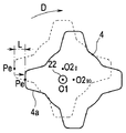
- an endoscope 1 includes an insertion portion 2 that is inserted into a subject, an operation portion 3 that is connected to the proximal side of the insertion portion 2, and the operation portion. 3 is provided with a universal cord 8 extended from 3 and a connector 9 provided at the extended end of the universal cord 8.
- the endoscope 1 is electrically connected to an external device (not shown) such as a video processor or a light source device via a connector 9.
- the operation unit 3 is rotated and operated as an operation member for bending the up / down bending operation knob 4 and the bending unit 12 in the left / right direction as an operation member for bending the bending unit 12 of the insertion unit 2 in the up / down direction.
- Left and right bending operation knobs 5 are provided.
- the up / down bending operation knob 4 and the left / right bending operation knob 5 are disk-like members provided with five protrusions (4a) for hooking radially from the center (rotation center).
- the operation unit 3 is provided with a fixed lever 6 for fixing the turning position of the up / down bending operation knob 4 and a fixing knob 7 for fixing the turning position of the left / right bending operation knob 5.
- the insertion portion 2 has a distal end portion 11, a bending portion 12, and a flexible tube portion 13 connected in order from the distal end side, and is formed in an elongated shape so that it can be easily inserted into a subject.
- the bending portion 12 is bent in, for example, four directions, up, down, left, and right, by the turning operation of the up / down bending operation knob 4 and the left / right bending operation knob 5, thereby providing an imaging unit 30 described later provided in the distal end portion 11.
- the observation direction can be changed, and the insertability of the tip 11 in the subject can be improved.
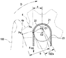
- the endoscope 1 is a chain connected to a center (rotation center) O ⁇ b> 1 of the vertical bending operation knob 4 in the operation unit 3 via a pivot shaft 22 that is pivotally supported.
- a sprocket 21 as a disk member which is a wheel is provided.
- the disc member may be a pulley instead of the sprocket 21.
- the sprocket 21 When the bending portion 12 is linear, the sprocket 21 is decentered in a predetermined direction at a predetermined distance d from the rotation center O1 of the up / down bending operation knob 4, here the center O2 is above the operation portion 3. As shown in FIG.
- the rotation center O1 is eccentric with respect to the center O2 by a predetermined distance d along the longitudinal direction of the operation unit 3 toward the tip side.
- the rotation shaft 22 and the center (rotation center) O1 of the up / down bending operation knob 4 and the center O2 of the sprocket 21 are inserted when the bending portion 12 is in a neutral state (neutral initial state). It is in the state arranged along the central axis of the part 2.
- This sprocket 21 is engaged with a chain 23 which is a part of the pulling member only in an upper semicircular portion.
- a pair of operation wires 25 that are a part of the pulling member are connected to both ends of the chain 23 via a connecting member 24.
- the operation wire 25 is inserted from the operation unit 3 into the insertion unit 2 and has a distal end connected to a cutting edge bending piece provided at a distal end (not shown) in the bending unit 12.
- the bending portion 12 has a plurality of bending pieces (not shown) rotatably connected to the inside thereof, and the operation wire 25 is pulled and relaxed by the rotation of the bending operation knob 4 for up and down. It is comprised so that it may curve to.
- the operation unit 3 is provided with a sprocket 21, a chain 23, an operation wire 25, and the like corresponding to the left / right bending operation knob 5 in the same manner as the up / down bending operation knob 4. Therefore, the bending portion 12 is configured to bend in the left-right direction when the operation wire 25 is pulled and loosened by the rotation of the left-right bending operation knob 5. Since such a bending structure in which a plurality of bending pieces are provided in the bending portion 12 is well known, description thereof is omitted.
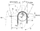
- the endoscope 1 includes a center (rotation center) O1 of the up / down bending operation knob 4 provided in the operation unit 3, that is, a center (rotation center) O1 of the rotation shaft 22.
- the point at which the user's finger (thumb) F is put on the protrusion 4a of the up / down bending operation knob 4 is defined as an action point Pe
- the distance from the action point Pe to the rotation center O1 is defined as a predetermined distance b.
- a point on the extension line in the lateral direction (horizontal direction) of the center O2 of the sprocket 21 will be described as a force point Pa.
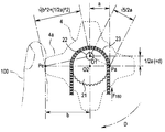
- the bending operation knob 4 for up and down changes the bending angle of the bending portion 12 to be bent upward from 0 (zero) degree as shown in FIG. In doing so, as shown in FIG. 4, a 90-degree rotation operation about the rotation center O1 is performed in the counterclockwise direction.
- the distance from the rotation center O1 to the power point Pa can be obtained by the three-square theorem.
- the bending angle of the bending portion 12 is changed to 180 degrees.
- a 90-degree rotation operation about the rotation center O1 is performed in the counterclockwise direction.
- the sprocket 21 rotates 90 degrees around the rotation center O1 so as to approach the user's finger 100.
- the up / down bending operation knob 4 rotates counterclockwise. Then, a rotation operation of 180 degrees around the rotation center O1 is performed.
- operation force F180 required bending force F 180 obtained while the bending angle of the bending portion 12 shown in FIG. 5 to 180 degrees, the distance ⁇ 5 / 2 ⁇ a from rotation center O1 to force point Pa From the relationship of the distance b from the rotation center O1 to the action point Pe, the following equation (3) is obtained.
- Operation force F180 F 180 ⁇ ⁇ 5 / 2 ⁇ a / b ... (3).
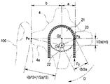
- the up / down bending operation knob 4 changes the bending angle of the bending portion 12 to be bent downward from 0 (zero) degree, in which the bending angle of the bending portion 12 is the initial linear shape shown in FIG. ( ⁇ 90 degrees), as shown in FIG. 7, a rotation operation of 90 degrees ( ⁇ 90 degrees) about the rotation center O1 is performed in the counterclockwise direction.
- the operation force F0 necessary operation force F 0 is the pulling force of the operating wire 25 to the bending portion 12 to bend operation when to further bend downward side
- the following equation (4) is obtained.
- Operation force F0 F 0 ⁇ ⁇ 5 / 2 ⁇ a / b ... (4).
- the up / down bending operation knob 4 is further bent downward from the bending angle of the bending portion 12 shown in FIG. 7 of 90 degrees ( ⁇ 90 degrees) to change the bending angle of the bending section 12 to 180 degrees.
- ( ⁇ 180 degrees) is set, as shown in FIG. 8, a rotation operation of 90 degrees ( ⁇ 90 degrees) about the rotation center O1 is further performed in the counterclockwise direction.
- the sprocket 21 rotates 90 degrees ( ⁇ 90 degrees) around the rotation center O1 so as to be separated from the user's finger 100.
- the up / down bending operation knob 4 changes the bending angle of the bending portion 12 downward from 180 ° ( ⁇ 180 °) from the state where the bending angle of the bending portion 12 shown in FIG. 6 is 0 (zero) degree.
- a rotation operation of 180 degrees ( ⁇ 180 degrees) about the rotation center O1 is performed counterclockwise.
- the operation force amount necessary for the bending force F 180 when the bending angle is 180 degrees (-180 degrees) of the bending portion 12 F 180 (F 180) is that shown in FIG. 8, emphasis Pa from the rotation center O1 (5) ⁇ a and the distance b from the rotation center O1 to the action point Pe, the following equation (6) is obtained.
- Operation force F180 F 180 ⁇ ⁇ 5 / 2 ⁇ a / b ... (6).
- the general endoscope has a configuration in which the center O1 of the up / down bending operation knob 4 and the center O2 of the sprocket 21 are not coincident with each other, and therefore, the distance from the rotation center O1 to the force point Pa.
- the relationship between a and the distance b from the rotation center O1 to the action point Pe is unchanged.
- the bending force of the operation wire 25 for bending the bending portion 12 when bending the bending portion 12 from 0 degree to further upward and downward is changed to an operation force amount F 0 .
- the required amount of operation force F0 is expressed by the following equation (7) from the relationship between the distance a from the rotation center O1 to the force point Pa and the distance b from the rotation center O1 to the action point Pe in the vertical direction.
- Operation force F0 F 0 ⁇ a / b ... (7).
- the amount of operation force required for the bending force amount F 90 for bending the bending portion 12 when bending the bending portion 12 from 90 degrees ( ⁇ 90 degrees) further up and down.
- F90 (F-90) is expressed by the following equation (8) because the distance a from the rotation center O1 to the force point Pa and the distance b from the rotation center O1 to the action point Pe are not changed in the vertical direction.
- Operation force F90 (F90) F 90 ⁇ a / b ... (8).
- the endoscope 1 has the above formulas (1) to (1) to (6) is as follows.
- the endoscope 1 of the present embodiment is curved when compared with a linear change indicated by a broken line in the figure due to the amount of operation force of a conventional (existing) general endoscope.
- the endoscope 1 does not give a sense of incongruity to the user's operation because the amount of operation force changes to draw an arc.
- the endoscope has an initial operation force amount for rotating the bending operation knobs 4 and 5 when the bending portion 12 is bent from the straight line state (neutral initial state) compared to a conventional general endoscope.
- the amount of operating force is immediately reduced as compared with the conventional technique, even a powerless operator can easily bend the bending portion 12 without difficulty.
- the endoscope 1 is configured such that when the bending portion 12 performs a bending operation from a straight state, the operation force amount of each of the bending operation knobs 4 and 5 is reduced immediately from the initial movement so that the bending operation can be easily performed with a light force. .
- the amount of operation force is reduced immediately after turning the bending operation knob when the bending portion 12 is bent from the linear state (the neutral initial state). Even a powerless operator can be configured to easily perform the bending operation of the bending portion 12.
- the endoscope 1 when the bending operation is performed on the bending portion 12, the endoscope 1 can be easily bent with a light force by reducing the amount of operation force of the bending operation knob from the straight state, and the bending operability is improved. To do.
- the turning amounts of the bending operation knobs 4 and 5 are 180 degrees ( ⁇ 180 degrees). It is the same as a general endoscope set to be. This is for easy understanding in calculation. For example, when the bending angle of the bending portion 12 is 180 degrees ( ⁇ 180 degrees), the endoscope 1 is smaller than a general endoscope, That is, you may set so that the amount of rotations of each bending operation knob 4 and 5 may be less than 180 degree
- FIGS. 10 to 20 relate to the second embodiment of the present invention
- FIG. 10 is a schematic view showing the turning position of the bending operation knob when the bending portion is bent upward from the initial state
- FIG. 11 is the bending portion
- FIG. 12 is a schematic view showing the turning position of the bending operation knob when the bending portion is bent 90 degrees upward
- FIG. 12 is a schematic view showing the turning position of the bending operation knob when the bending portion is bent 180 degrees upward
- 13 is a schematic diagram showing the turning position of the bending operation knob when the bending portion is bent downward from the initial state
- FIG. 14 shows the turning position of the bending operation knob when the bending portion is bent 90 degrees downward.
- FIG. 15 is a schematic diagram showing the turning position of the bending operation knob when the bending portion is bent downward 180 degrees
- FIG. 16 is a graph showing the change in the operation force of the bending operation knob with respect to the bending angle of the bending portion.
- Figure 17 shows the curved part upward 90 degrees from the initial state.
- FIG. 18 is a schematic diagram for explaining the movement of the bending operation knob when it is bent
- FIG. 18 is a schematic diagram for explaining the movement of the bending operation knob when the bending part is bent 180 degrees upward from 90 degrees
- FIG. FIG. 20 illustrates the movement of the bending operation knob when the bending portion is bent 180 degrees downward from the 90 degree state.
- the endoscope 1 of the present embodiment is arranged so that the sprocket 21 and the centers of the bending operation knobs 4 and 5 (O2 in the figure) coincide.
- the up / down bending operation knob 4 is illustrated.
- the up / down bending operation knob 4 (and the left / right bending operation knob 5) here is a disk-like member provided with four protrusions 4a for finger-hooking radially from the center (rotation center).
- the number of the bending operation knobs 4 and 5 is not limited to four, but may be five as in the first embodiment, and may be any number as long as there are a plurality of them.
- the endoscope 1 When the bending portion 12 is linear, the endoscope 1 has the vertical bending knob 4 and the sprocket 21 at a predetermined distance d from the rotation center O1 of the rotation shaft 22 in a predetermined direction, here.
- the center O2 is pivotally supported on the upper side which is the base end side of the operation unit 3 so as to be eccentric.
- the up and down bending operation knob 4 and the sprocket 21 are deviated from the center O2 by a predetermined distance d toward the distal end side of the rotation center O1 of the rotation shaft 22 along the longitudinal direction of the operation unit 3. Yes.
- the center (rotation center) O1 of the rotation shaft 22 and the center O2 of the sprocket 21 and the up / down bending operation knob 4 are the center of the insertion portion 2 when the bending portion 12 is in a straight line state (neutral initial state). It is in a state of being arranged side by side along the axis.
- left and right bending operation knobs 5 are the same, and the description of these components is omitted.
- the up / down bending operation knob 4 changes the bending angle of the bending portion 12 to be bent upward from 0 (zero) degree as shown in FIG. At this time, as shown in FIG. 11, a 90-degree rotation operation about the rotation center O1 is performed in the counterclockwise direction.
- the operation force amount necessary for the operation force amount F 0 that is the pulling force of the operation wire 25 for bending the bending portion 12 when bending the bending portion 12 from 0 degree to further upward is as follows: From the relationship between the distance ⁇ 5 / 2 ⁇ a from the rotation center O1 to the force point Pa and the distance ⁇ (b ⁇ 2 + (1/2 ⁇ a) ⁇ 2) from the rotation center O1 to the action point Pe, Equation (10) is obtained.
- Manipulation force F0 F 0 ⁇ ⁇ 5 / 2 ⁇ a / ⁇ (b 2 + (1/2 ⁇ a) 2) (10).
- the distance from the rotation center O1 to the force point Pa and the distance from the rotation center O1 to the action point Pe can be obtained by the three-square theorem.
- the bending angle of the bending portion 12 is 180 degrees.
- a 90-degree rotation operation about the rotation center O1 is performed in the counterclockwise direction.
- the up / down bending operation knob 4 and the sprocket 21 are rotated by 90 degrees around the rotation center O ⁇ b> 1 so as to approach the user's finger 100.
- the up / down bending operation knob 4 rotates counterclockwise when the bending angle of the bending portion 12 shown in FIG. 10 is 0 (zero) degree and the bending angle of the bending portion 12 is 180 degrees upward. Then, a rotation operation of 180 degrees around the rotation center O1 is performed.
- operation force F180 required bending force F 180 obtained while the bending angle of the bending portion 12 shown in FIG. 12 to 180 degrees, the distance ⁇ 5 / 2 ⁇ a from rotation center O1 to force point Pa From the relationship of the distance ⁇ (b ⁇ 2 + (1/2 ⁇ a) ⁇ 2) from the rotation center O1 to the action point Pe, the following equation (12) is obtained.
- Operation force F180 F 180 ⁇ ⁇ 5 / 2 ⁇ a / ⁇ (b ⁇ 2 + (1/2 ⁇ a) ⁇ 2) ... (12).
- the up / down bending operation knob 4 changes the bending angle of the bending portion 12 to be bent downward from 0 (zero) degree, in which the bending angle of the bending portion 12 is the initial linear shape shown in FIG. ( ⁇ 90 degrees), as shown in FIG. 14, a rotation operation of 90 degrees ( ⁇ 90 degrees) around the rotation center O1 is performed in the counterclockwise direction.
- the operation force F0 necessary operation force F 0 is the pulling force of the operating wire 25 to the bending portion 12 to bend operation when to further bend downward side
- Equation (13) is obtained.
- Manipulation force F0 F 0 ⁇ ⁇ 5 / 2 ⁇ a / ⁇ (b 2 + (1/2 ⁇ a) 2) (13).
- the up / down bending operation knob 4 is further bent downward from the state in which the bending angle of the bending portion 12 shown in FIG. 14 is 90 degrees ( ⁇ 90 degrees), so that the bending angle of the bending section 12 is 180 degrees.
- the angle is set to ( ⁇ 180 degrees)
- a rotation operation of 90 degrees ( ⁇ 90 degrees) around the rotation center O1 is further performed in the counterclockwise direction.
- the up / down bending operation knob 4 and the sprocket 21 rotate 90 degrees ( ⁇ 90 degrees) around the rotation center O1 so as to be separated from the user's finger 100.
- the up / down bending operation knob 4 changes the bending angle of the bending portion 12 downward from 180 ° ( ⁇ 180 °) from the state where the bending angle of the bending portion 12 shown in FIG. 13 is 0 (zero) degree.
- a rotation operation of 180 degrees ( ⁇ 180 degrees) about the rotation center O1 is performed counterclockwise.
- operation force F180 required bending force F 180 obtained while the bending angle of the bending portion 12 to 180 degrees (-180 degrees) shown in FIG. 15, the distance from the rotation center O1 to force point Pa ⁇ 5 From the relationship of / 2 ⁇ a and the distance ⁇ (b ⁇ 2 + (1/2 ⁇ a) ⁇ 2) from the rotation center O1 to the action point Pe, the following equation (15) is obtained.
- Operation force F180 F 180 ⁇ ⁇ 5 / 2 ⁇ a / ⁇ (b ⁇ 2 + (1/2 ⁇ a) ⁇ 2) ... (15).
- operation force amount necessary for the F 0 F0 is the relationship between the distance b to the point Pe from the distance a and the rotation center O1 of the pivot O1 to force point Pa in the vertical direction both by the following expression (16).
- Operation force F0 F 0 ⁇ a / b ... (16).
- the amount of operation force required for the bending force amount F 90 for bending the bending portion 12 when bending the bending portion 12 from 90 degrees ( ⁇ 90 degrees) further up and down.
- F90 is expressed by the following equation (17) because the distance a from the rotation center O1 to the force point Pa and the distance b from the rotation center O1 to the action point Pe are not changed in the vertical direction.
- Operation force F90 F 90 ⁇ a / b ... (17).
- operation force F180 required bending force F 180 obtained while the bending angle of the bending portion 12 to 180 degrees (-180 degrees), the force point Pa from the rotation center O1 in the vertical direction both Since the distance a from the rotation center O1 to the action point Pe does not change, the following equation (18) is obtained from the relationship.
- Operation force F180 F 180 ⁇ a / b ... (18).
- the endoscope 1 has the above formulas (11) to (11) to (15) is as follows.
- the endoscope 1 of the present embodiment is curved when compared with a linear change indicated by a broken line in the figure due to the amount of operation force of a conventional (existing) general endoscope.
- the endoscope 1 does not give a sense of incongruity to the user's operation because the operation force changes so as to draw an arc as in the first embodiment.
- the endoscope has an initial operation force amount for rotating the bending operation knobs 4 and 5 when the bending portion 12 is bent from the straight state (the neutral initial state).
- the operation force is slightly increased as compared with the conventional general endoscope, the bending force can be easily and easily operated even by a powerless operator because the amount of operation force is reduced as compared with the conventional endoscope.
- the endoscope 1 is configured such that when the bending portion 12 performs a bending operation from a straight state, the operation force amount of each of the bending operation knobs 4 and 5 is reduced immediately from the initial movement so that the bending operation can be easily performed with a light force. .
- the endoscope 1 has an operation force amount F90 for bending the frequently used bending portion 12 upward at a bending angle of 90 degrees.
- the bending operation can be easily performed with a very light force and the bending operability is further improved.
- the turning center O1 of the turning shaft 22 is decentered by a predetermined distance d along the longitudinal direction of the operation unit 3 with respect to the center O2 of the up / down bending operation knob 4. Therefore, as shown in FIGS. 17 and 18, during the bending operation in which the bending portion 12 is bent upward from a bending angle of 0 degrees to 180 degrees, the protrusion 4 a of the bending operation knob 4 for up and down is the user's finger 100. Is rotated around the rotation center O1 so as to approach at a predetermined distance L.
- the endoscope 1 has the protrusion 4a of the up / down bending operation knob 4 at the time of a bending operation in which the bending portion 12 is bent downward from 0 degree to 180 degrees. It rotates around the rotation center O1 so as to move away from the user's finger 100 by a predetermined distance L.
- the endoscope 1 has many opportunities to bend the bending portion 12 upward, and the protrusion 4a of the upper bending operation knob 4 approaches the finger 100 particularly for an operator with a small hand. There is also an advantage that it is easier to operate.
Landscapes
- Health & Medical Sciences (AREA)
- Life Sciences & Earth Sciences (AREA)
- Surgery (AREA)
- Biomedical Technology (AREA)
- Medical Informatics (AREA)
- Optics & Photonics (AREA)
- Pathology (AREA)
- Radiology & Medical Imaging (AREA)
- Biophysics (AREA)
- Engineering & Computer Science (AREA)
- Physics & Mathematics (AREA)
- Heart & Thoracic Surgery (AREA)
- Nuclear Medicine, Radiotherapy & Molecular Imaging (AREA)
- Molecular Biology (AREA)
- Animal Behavior & Ethology (AREA)
- General Health & Medical Sciences (AREA)
- Public Health (AREA)
- Veterinary Medicine (AREA)
- Endoscopes (AREA)
- Instruments For Viewing The Inside Of Hollow Bodies (AREA)
Abstract
Description
図1から図9は本発明の第1の実施の形態に係わり、図1は内視鏡の全体構成を示す図、図2は湾曲操作ノブに連動して回動する回動機構によって湾曲部を湾曲操作する構成を示す内視鏡の概略図、図3は湾曲部を初期状態から上方に湾曲させるときの湾曲操作ノブの回動位置を示す概略図、図4は湾曲部を上方に90度湾曲させたときの湾曲操作ノブの回動位置を示す概略図、図5は湾曲部を上方に180度湾曲させたときの湾曲操作ノブの回動位置を示す概略図、図6は湾曲部を初期状態から下方に湾曲させるときの湾曲操作ノブの回動位置を示す概略図、図7は湾曲部を下方に90度湾曲させたときの湾曲操作ノブの回動位置を示す概略図、図8は湾曲部を下方に180度湾曲させたときの湾曲操作ノブの回動位置を示す概略図、図9は湾曲部の湾曲角度に対する湾曲操作ノブの操作力量の変化を示すグラフである。
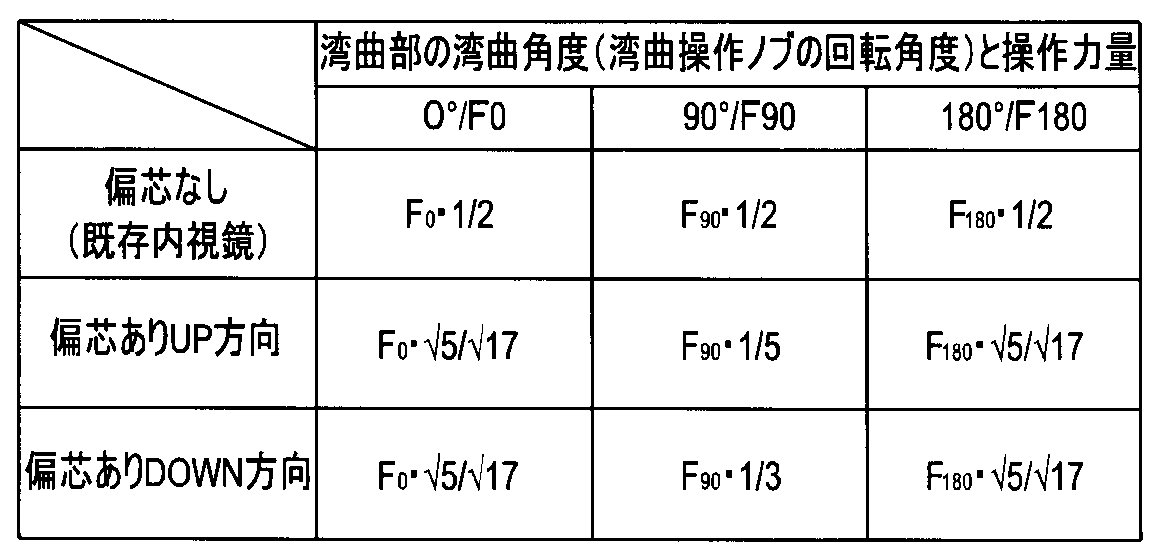
なお、ここでは説明の便宜のため、各湾曲操作ノブ4,5の回転角度に対する湾曲部12の湾曲角度が同じ角度としている。
操作力量F0=F0・√5/2・a/b…(1)。
操作力量F90=F90・1/2・a/b…(2)。
操作力量F180=F180・√5/2・a/b…(3)。
操作力量F0=F0・√5/2・a/b…(4)。
操作力量F90=F90・1/2a/b…(5)。
操作力量F180=F180・√5/2・a/b…(6)。
操作力量F0=F0・a/b…(7)。
操作力量F90(F-90)=F90・a/b…(8)。
操作力量F180(F-180)=F180・a/b…(9)。

F90(F-90)=F90・a・1/2/2・a=F90・1/4…(2),(5)
F180(F-180)=F180・a・1/2・a=F180・√5/4…(3),(6)。
F90(F-90)=F90・a/2・a=F90・1/2…(8)
F180(F-180)=F180・a/2・a=F180・1/2…(9)
以上を纏めた表が以下となる。

次に、本発明の第2の実施の形態の内視鏡について、図面に基づいて、以下に説明する。
なお、以下の説明においては、上述した第1の実施の形態に記載した同一の構成要素について、同じ符号を用いて、それら構成要素の詳細な説明を省略する。
上下用湾曲操作ノブ4は、図10に示す、湾曲部12の湾曲角度が初期状態である直線状となる0(ゼロ)度から、上方側へ湾曲させる湾曲部12の湾曲角度を90度にするとき、図11に示すように、反時計回り方向に回動中心O1回りの90度の回動操作がなされる。
操作力量F0=F0・√5/2・a/√(b^2+(1/2・a)^2)…(10)。
操作力量F90=F90・1/2・a/(b+1/2・a)…(11)。
操作力量F180=F180・√5/2・a/√(b^2+(1/2・a)^2)…(12)。
操作力量F0=F0・√5/2・a/√(b^2+(1/2・a)^2)…(13)。
操作力量F90=F90・1/2a/(b-1/2・a)…(14)。
操作力量F180=F180・√5/2・a/√(b^2+(1/2・a)^2)…(15)。
操作力量F0=F0・a/b…(16)。
操作力量F90=F90・a/b…(17)。
操作力量F180=F180・a/b…(18)。

F90=F90・1/2・a/(2・a+1/2・a)=F90・1/5…(11)
F90(F-90)=F90・1/2・a/(2・a-1/2・a)=F90・1/3…(14)
F180(F-180)=F180・√5/2・a/√{(2・a)^2+(1/2・a)^2}=F180・√5/√17…(12),(15)。
F90=F90・a/2・a=F90・1/2…(17)
F180=F180・a/2・a=F180・1/2…(18)
以上を纏めた表が以下となる。
Claims (6)
- 基端側となる手元側に設けられた操作部と、
前記操作部から先端側に延出し、湾曲部が配設された挿入部と、
前記湾曲部から前記挿入部内および前記操作部内に配設される複数の牽引部材と、
前記操作部内に回動自在に設けられ、前記複数の牽引部材が外周に架設され、回動することで前記複数の牽引部材を牽引弛緩する円板部材と、
前記操作部に回動自在に配設され、前記円板部材を回動して前記湾曲部を湾曲操作する操作部材と、
前記湾曲部が直線状となる初期状態において、前記円板部材の中心に対して、所定の距離だけ先端側へ偏心した位置で前記円板部材および前記操作部材を前記操作部に対して回動自在に軸支する回動軸と、
を備えることを特徴とする内視鏡。 - 前記回動軸の中心と前記操作部材の中心が一致していることを特徴とする請求項1に記載の内視鏡。
- 前記湾曲部が前記初期状態のときに、前記回動軸および前記操作部材の中心と前記円板部材の中心が前記挿入部の中心軸に沿って並設されていることを特徴とする請求項2に記載の内視鏡。
- 前記円板部材の中心と前記操作部材の中心が一致していることを特徴とする請求項1に記載の内視鏡。
- 前記湾曲部が前記初期状態のときに、前記回動軸の中心と前記円板部材および前記操作部材の中心が前記挿入部の中心軸に沿って並設されていることを特徴とする請求項4に記載の内視鏡。
- 前記円板部材がチェーンホイールであって、
前記牽引部材が前記チェーンホイールに噛合するチェーンと、前記チェーンの両端に接続された一対のワイヤであることを特徴とする請求項1から請求項5のいずれか1項に記載の内視鏡。
Priority Applications (4)
| Application Number | Priority Date | Filing Date | Title |
|---|---|---|---|
| JP2016505641A JP5948526B1 (ja) | 2014-09-26 | 2015-03-18 | 内視鏡 |
| CN201580011539.XA CN106061362B (zh) | 2014-09-26 | 2015-03-18 | 内窥镜 |
| EP15843376.3A EP3103375A4 (en) | 2014-09-26 | 2015-03-18 | Endoscope |
| US15/252,767 US10117567B2 (en) | 2014-09-26 | 2016-08-31 | Endoscope |
Applications Claiming Priority (2)
| Application Number | Priority Date | Filing Date | Title |
|---|---|---|---|
| JP2014-196842 | 2014-09-26 | ||
| JP2014196842 | 2014-09-26 |
Related Child Applications (1)
| Application Number | Title | Priority Date | Filing Date |
|---|---|---|---|
| US15/252,767 Continuation US10117567B2 (en) | 2014-09-26 | 2016-08-31 | Endoscope |
Publications (1)
| Publication Number | Publication Date |
|---|---|
| WO2016047171A1 true WO2016047171A1 (ja) | 2016-03-31 |
Family
ID=55580713
Family Applications (1)
| Application Number | Title | Priority Date | Filing Date |
|---|---|---|---|
| PCT/JP2015/058039 Ceased WO2016047171A1 (ja) | 2014-09-26 | 2015-03-18 | 内視鏡 |
Country Status (5)
| Country | Link |
|---|---|
| US (1) | US10117567B2 (ja) |
| EP (1) | EP3103375A4 (ja) |
| JP (1) | JP5948526B1 (ja) |
| CN (1) | CN106061362B (ja) |
| WO (1) | WO2016047171A1 (ja) |
Families Citing this family (3)
| Publication number | Priority date | Publication date | Assignee | Title |
|---|---|---|---|---|
| CA3125227A1 (en) | 2019-01-11 | 2020-07-16 | Dragonfly Endoscopy Llc | Endoscopic device and methods of use thereof |
| WO2020183366A1 (en) * | 2019-03-11 | 2020-09-17 | Boston Scientific Limited | Knobs for endoscopes with improved usability and ergonomics |
| CN119235235B (zh) * | 2024-12-06 | 2025-03-04 | 湖南省华芯医疗器械有限公司 | 拨轮组件、牵引机构、内窥镜及牵引绳张紧方法 |
Citations (3)
| Publication number | Priority date | Publication date | Assignee | Title |
|---|---|---|---|---|
| JP2002165753A (ja) * | 2000-12-05 | 2002-06-11 | Asahi Optical Co Ltd | 内視鏡の湾曲操作装置 |
| JP2007061218A (ja) * | 2005-08-29 | 2007-03-15 | Olympus Medical Systems Corp | 内視鏡 |
| JP2008142199A (ja) * | 2006-12-07 | 2008-06-26 | Olympus Corp | 内視鏡および内視鏡の湾曲操作装置 |
Family Cites Families (4)
| Publication number | Priority date | Publication date | Assignee | Title |
|---|---|---|---|---|
| EP2649922A4 (en) * | 2011-02-28 | 2018-01-17 | Olympus Corporation | Endoscope and medical apparatus |
| CN103619230B (zh) * | 2011-06-16 | 2016-08-17 | 奥林巴斯株式会社 | 内窥镜 |
| JP5416311B2 (ja) * | 2011-07-11 | 2014-02-12 | オリンパスメディカルシステムズ株式会社 | 内視鏡 |
| WO2013154048A1 (ja) * | 2012-04-12 | 2013-10-17 | オリンパスメディカルシステムズ株式会社 | 内視鏡 |
-
2015
- 2015-03-18 WO PCT/JP2015/058039 patent/WO2016047171A1/ja not_active Ceased
- 2015-03-18 JP JP2016505641A patent/JP5948526B1/ja active Active
- 2015-03-18 EP EP15843376.3A patent/EP3103375A4/en not_active Withdrawn
- 2015-03-18 CN CN201580011539.XA patent/CN106061362B/zh active Active
-
2016
- 2016-08-31 US US15/252,767 patent/US10117567B2/en active Active
Patent Citations (3)
| Publication number | Priority date | Publication date | Assignee | Title |
|---|---|---|---|---|
| JP2002165753A (ja) * | 2000-12-05 | 2002-06-11 | Asahi Optical Co Ltd | 内視鏡の湾曲操作装置 |
| JP2007061218A (ja) * | 2005-08-29 | 2007-03-15 | Olympus Medical Systems Corp | 内視鏡 |
| JP2008142199A (ja) * | 2006-12-07 | 2008-06-26 | Olympus Corp | 内視鏡および内視鏡の湾曲操作装置 |
Non-Patent Citations (1)
| Title |
|---|
| See also references of EP3103375A4 * |
Also Published As
| Publication number | Publication date |
|---|---|
| EP3103375A4 (en) | 2017-12-06 |
| US10117567B2 (en) | 2018-11-06 |
| JP5948526B1 (ja) | 2016-07-06 |
| CN106061362B (zh) | 2018-04-06 |
| EP3103375A1 (en) | 2016-12-14 |
| JPWO2016047171A1 (ja) | 2017-04-27 |
| US20160367111A1 (en) | 2016-12-22 |
| CN106061362A (zh) | 2016-10-26 |
Similar Documents
| Publication | Publication Date | Title |
|---|---|---|
| US9743827B2 (en) | Endoscope | |
| JP5930255B2 (ja) | 内視鏡 | |
| US10149608B2 (en) | Bending portion for endoscope and endoscope including bending portion for endoscope | |
| JP6081684B1 (ja) | 内視鏡 | |
| EP2997877A1 (en) | Bending control mechanism for endoscope | |
| CN108697303B (zh) | 弯曲操作装置和内窥镜 | |
| JP5945642B2 (ja) | 内視鏡の湾曲操作機構 | |
| JP5948526B1 (ja) | 内視鏡 | |
| JPWO2016147457A1 (ja) | 湾曲操作装置及び内視鏡 | |
| JPWO2018079061A1 (ja) | 内視鏡 | |
| JP2018000741A (ja) | 内視鏡用ワイヤ牽引機構及び内視鏡 | |
| EP2617347B1 (en) | Endoscope | |
| WO2017002423A1 (ja) | 内視鏡 | |
| KR101923430B1 (ko) | 양방향 굴곡 기능과 사용 편의성이 향상된 내시경용 의료기기 | |
| JP6250232B1 (ja) | 湾曲操作装置及びこれを適用した内視鏡 | |
| CN106413509B (zh) | 拨盘单元和导入装置 | |
| JPWO2019069608A1 (ja) | 内視鏡 | |
| CN105338874B (zh) | 导入装置、内窥镜装置 | |
| WO2017090533A1 (ja) | 内視鏡用操作機構及び内視鏡 | |
| CN111200962A (zh) | 内窥镜用操作线牵拉装置 | |
| JPWO2017145431A1 (ja) | 内視鏡 | |
| JP6042796B2 (ja) | 挿入機器 | |
| WO2015159631A1 (ja) | 内視鏡 |
Legal Events
| Date | Code | Title | Description |
|---|---|---|---|
| ENP | Entry into the national phase |
Ref document number: 2016505641 Country of ref document: JP Kind code of ref document: A |
|
| 121 | Ep: the epo has been informed by wipo that ep was designated in this application |
Ref document number: 15843376 Country of ref document: EP Kind code of ref document: A1 |
|
| REEP | Request for entry into the european phase |
Ref document number: 2015843376 Country of ref document: EP |
|
| WWE | Wipo information: entry into national phase |
Ref document number: 2015843376 Country of ref document: EP |
|
| NENP | Non-entry into the national phase |
Ref country code: DE |