WO2016047620A1 - 液体供給システム - Google Patents
液体供給システム Download PDFInfo
- Publication number
- WO2016047620A1 WO2016047620A1 PCT/JP2015/076750 JP2015076750W WO2016047620A1 WO 2016047620 A1 WO2016047620 A1 WO 2016047620A1 JP 2015076750 W JP2015076750 W JP 2015076750W WO 2016047620 A1 WO2016047620 A1 WO 2016047620A1
- Authority
- WO
- WIPO (PCT)
- Prior art keywords
- bellows
- liquid
- pump chamber
- container
- supply system
- Prior art date
- Legal status (The legal status is an assumption and is not a legal conclusion. Google has not performed a legal analysis and makes no representation as to the accuracy of the status listed.)
- Ceased
Links
Images



Classifications
-
- F—MECHANICAL ENGINEERING; LIGHTING; HEATING; WEAPONS; BLASTING
- F04—POSITIVE - DISPLACEMENT MACHINES FOR LIQUIDS; PUMPS FOR LIQUIDS OR ELASTIC FLUIDS
- F04B—POSITIVE-DISPLACEMENT MACHINES FOR LIQUIDS; PUMPS
- F04B15/00—Pumps adapted to handle specific fluids, e.g. by selection of specific materials for pumps or pump parts
- F04B15/06—Pumps adapted to handle specific fluids, e.g. by selection of specific materials for pumps or pump parts for liquids near their boiling point, e.g. under subnormal pressure
- F04B15/08—Pumps adapted to handle specific fluids, e.g. by selection of specific materials for pumps or pump parts for liquids near their boiling point, e.g. under subnormal pressure the liquids having low boiling points
-
- F—MECHANICAL ENGINEERING; LIGHTING; HEATING; WEAPONS; BLASTING
- F04—POSITIVE - DISPLACEMENT MACHINES FOR LIQUIDS; PUMPS FOR LIQUIDS OR ELASTIC FLUIDS
- F04B—POSITIVE-DISPLACEMENT MACHINES FOR LIQUIDS; PUMPS
- F04B11/00—Equalisation of pulses, e.g. by use of air vessels; Counteracting cavitation
- F04B11/005—Equalisation of pulses, e.g. by use of air vessels; Counteracting cavitation using two or more pumping pistons
-
- F—MECHANICAL ENGINEERING; LIGHTING; HEATING; WEAPONS; BLASTING
- F04—POSITIVE - DISPLACEMENT MACHINES FOR LIQUIDS; PUMPS FOR LIQUIDS OR ELASTIC FLUIDS
- F04B—POSITIVE-DISPLACEMENT MACHINES FOR LIQUIDS; PUMPS
- F04B43/00—Machines, pumps, or pumping installations having flexible working members
- F04B43/08—Machines, pumps, or pumping installations having flexible working members having tubular flexible members
-
- F—MECHANICAL ENGINEERING; LIGHTING; HEATING; WEAPONS; BLASTING
- F04—POSITIVE - DISPLACEMENT MACHINES FOR LIQUIDS; PUMPS FOR LIQUIDS OR ELASTIC FLUIDS
- F04B—POSITIVE-DISPLACEMENT MACHINES FOR LIQUIDS; PUMPS
- F04B43/00—Machines, pumps, or pumping installations having flexible working members
- F04B43/08—Machines, pumps, or pumping installations having flexible working members having tubular flexible members
- F04B43/086—Machines, pumps, or pumping installations having flexible working members having tubular flexible members with two or more tubular flexible members in parallel
Definitions
- the present invention relates to a liquid supply system for supplying an ultra-low temperature liquid such as liquid nitrogen or liquid helium.
- a technique for supplying an ultra-low temperature liquid such as liquid nitrogen to a vacuum heat insulating tube containing the superconducting cable or the like is known.
- a liquid supply (circulation) system for the ultracold liquid is used to maintain the superconducting cable in a superconducting state for a cooled device equipped with a superconducting cable inside the vacuum insulating pipe. Is always supplied.
- an ultra-low temperature liquid circulation system is often used on the assumption that only a liquid is circulated, and a centrifugal pump is typically employed as a pump mechanism in that case.
- a centrifugal pump is typically employed as a pump mechanism in that case.
- the cryogenic bellows pump using the metal bellows member is known as a pump structure which can implement
- the slurry may be damaged by hitting the metal bellows, or the metal material may be damaged by biting into the bellows portion.
- Patent Document 2 As a liquid supply system using a transfer liquid containing a precipitated substance such as slurry, a system using a resin bellows is known (Patent Document 2).
- Patent Document 2 a system using a resin bellows is known (Patent Document 2).
- a resin pump since the flexibility is poor compared to a metal material and the stroke amount cannot be secured, it is difficult to obtain the pump performance necessary to supply a large flow rate, and buckling is performed compared to a metal material. there is a possibility.
- An object of the present invention is to provide a liquid supply system capable of realizing a stable pumping operation even when an ultra-low temperature liquid containing a slurry is a target for liquid feeding.
- a liquid supply system comprises: A liquid supply system for supplying an ultra-low temperature liquid containing a slurry component by expansion and contraction of a bellows, In the bellows, at least a region in contact with the liquid is coated with a resin having a low temperature embrittlement temperature equal to or lower than a use temperature of the liquid supply system.
- the region of the bellows where ultra-low temperature liquid contacts is coated with a resin having a low temperature embrittlement temperature lower than the system operating temperature.
- the liquid supply system in the present invention is: A container configured to inhale liquid from a first passage communicating with the outside of the system and to deliver the inhaled liquid to a second passage communicating with the outside of the system; A first bellows and a second bellows arranged in series in the expansion / contraction direction inside the container, each first end portion on the side close to each other being fixed to the inner wall of the container, and each on the side far from each other A first bellows and a second bellows, each of which is configured to be movable in the extending and contracting direction, The first bellows and the second bellows are inserted into the container so that the second end portions of the first bellows and the second bellows are respectively fixed and reciprocated in the expansion and contraction direction by a driving source.
- a shaft to extend and contract A liquid supply system comprising: The outside of the first bellows in the container is a first pump chamber.
- the first pump chamber has a first suction port for sucking liquid from the first passage into the first pump chamber, and a suction port.
- a first delivery port for delivering the liquid from the first pump chamber to the second passage is provided,
- the outside of the second bellows in the container is a second pump chamber.
- the second pump chamber has a second suction port for sucking liquid from the first passage into the second pump chamber, and a suction port.
- a second outlet for delivering the liquid from the second pump chamber to the second passage is provided,
- a sealed space is formed inside the first bellows and the second bellows, At least a region facing the first pump chamber in the first bellows and a region facing the second pump chamber in the second bellows are coated with a resin having a low temperature embrittlement temperature equal to or lower than the use temperature of the liquid supply system. It is good to be.
- the second end of the first bellows and the second bellows are integrally moved in the expansion and contraction direction of the bellows by reciprocating movement of the shaft.
- One of the second bellows contracts and the other expands, and one of the first pump chamber and the second pump chamber sucks liquid from the first passage, and the other sends liquid to the second passage.
- the wetted parts of the first bellows and the second bellows that is, the regions facing the first pump chamber and the second pump chamber in each pump have a low temperature embrittlement temperature lower than the system operating temperature. It is coated with resin.
- the bellows expands and contracts during pump operation, the bellows is damaged due to collision between the slurry containing the liquid and the bellows surface, and biting of the slurry into the bellows bellows portion. Is suppressed. That is, the resin that coats the wetted area of the bellows has a low temperature embrittlement temperature lower than the system operating temperature, so that it can maintain elasticity during use, and deforms with respect to the impinging or biting slurry. By this, it can suppress that a bellows is damaged.
- the bellows when the bellows is made of metal, it is more difficult for heat to be transferred to the liquid when the coating resin is in contact with the liquid than when the metal bellows is in direct contact with the liquid.
- the temperature rise can be suppressed and maintained at a low temperature.
- the liquid can be continuously and alternately supplied from the first pump chamber and the second pump chamber by the reciprocating movement of the shaft, and the liquid supply with suppressed pulsation is possible.
- this pump operation when the pressure acting on the inner side (inner peripheral surface) of the first bellows and the second bellows does not change, it is possible to suppress the occurrence of buckling in the bellows, and a more stable pump operation. Can be realized.
- At least the region facing the first pump chamber and the second pump chamber in the container may be coated with the resin.
- a third bellows arranged in series in the expansion and contraction direction with respect to the second bellows, wherein one end is arranged such that the outer side becomes the second pump chamber and the inner side is opened to the outside of the container;
- a third bellows that is fixed to the container and whose other end is connected to the second end of the second bellows and that expands and contracts with the expansion and contraction of the second bellows;
- the shaft is inserted through the inside of the third bellows and connected to the second end, A region of the third bellows facing the second pump chamber may be coated with the resin.
- each bellows can be expanded and contracted, and there is no heat generation by sliding friction of a shaft. It can be configured. Even in such a configuration, the coated resin can suppress damage and heat transfer due to collision with the slurry contained in the liquid.
- a stable pumping operation can be realized even when an ultra-low temperature liquid containing slurry is a target for liquid feeding.
- FIG. 1 is a schematic diagram illustrating a configuration of a liquid supply system according to an embodiment of the present invention.
- FIG. 2 is a schematic diagram for explaining the operation of the liquid supply system according to the embodiment of the present invention.
- FIG. 3 is a diagram illustrating fluctuations in the discharge pressure of the liquid supply system according to the embodiment of the present invention.
- FIG. 4 is a diagram illustrating fluctuations in the discharge pressure of the liquid supply system according to a modification of the embodiment of the present invention.
- FIG. 5 is a schematic diagram for explaining the operation of the liquid supply system according to the conventional example.
- FIG. 6 is a diagram illustrating fluctuations in the discharge pressure of the liquid supply system according to the conventional example.
- FIG. 7 is a schematic diagram showing a liquid contact region in the liquid supply system according to the embodiment of the present invention.
- FIG. 8 is a schematic diagram illustrating a resin coating region in the liquid supply system according to the embodiment of the present invention.
- FIG. 1 is a schematic configuration diagram of a liquid supply system according to an embodiment of the present invention.
- the liquid supply system 10 is a pump device for a cryogenic fluid, and maintains the superconducting cable 32 in a superconducting state with respect to the cooled device 30 in which the superconducting cable 32 is provided inside the resin container 31. Therefore, the ultra-low temperature liquid L is constantly supplied into the container 31.
- the ultra-low temperature liquid L include liquid nitrogen and liquid helium, and liquids having a temperature equal to or lower than the temperature at which they become liquid can be used.
- the liquid supply system 10 generally includes a first container (outer container) 11 whose inside is evacuated, and a second container 12 arranged so as to be surrounded by a vacuum space inside the first container 11. .
- a first container (outer container) 11 whose inside is evacuated
- a second container 12 arranged so as to be surrounded by a vacuum space inside the first container 11.
- the second container 12 roughly, three bellows 41, 42, 43 are arranged in series in the extending and contracting direction, and the inside of the container is partitioned into three sealed spaces by these bellows 41-43.
- the second container 12 is supported inside the first container 11 by a support member 51 inserted from the outside of the first container 11 into the first container 11.
- the first bellows 41 and the second bellows 42 have the same diameter, and are arranged side by side in series in the respective expansion / contraction directions with the axis centers coincident.
- the first bellows 41 and the second bellows 42 are fixed to the inner wall of the second container 12 at respective end portions (first end portions) 41 b and 42 b on the sides close to each other. Further, in the first bellows 41 and the second bellows 42, the respective end portions (second end portions) 41a and 42a far from each other are integrated by fixing a shaft 15 which will be described later, and each expansion and contraction is performed. It is configured to be movable in the direction.
- the third bellows 43 is arranged in series on the opposite side of the second bellows 42 from the first bellows 41.
- the third bellows 43 has an outer diameter smaller than the inner diameter of the second bellows 42 and is disposed so that a part thereof enters the inside of the second bellows 42 in the expansion / contraction direction.
- One end 43 b of the third bellows 43 is fixed to the inner wall of the second container 12 so that the inside of the third bellows 43 is opened to the outside of the second container 12.
- the other end 43 a of the third bellows 43 is connected to the end 42 a of the second bellows 42, and the third bellows 43 expands and contracts with the expansion and contraction of the second bellows 42.
- the end 41a of the first bellows 41 is closed, and a sealed space formed by a region outside the first bellows 41 in the second container 12 constitutes the first pump chamber P1.
- a sealed space formed by a region outside the second bellows 42 and the third bellows 43 in the second container 12 constitutes the second pump chamber P2.
- the end portion 42a of the second bellows 42 and the end portion 43a of the third bellows 43 are closed, and the end portion 41b of the first bellows 41 and the end portion 42b of the second bellows 42 are open.
- the inner region of the first bellows 41 and the inner region of the second bellows 42 constitute one sealed space R1.
- the second container 12 has a first suction port 21 for sucking the liquid L into the first pump chamber P1 from a return passage (return pipe) K2 communicating with the outside of the system, and the sucked liquid L in the first pump chamber P1. And a first delivery port 22 for delivery to a supply passage (supply pipe) K1 communicating with the outside of the system. Further, the second container 12 sends out the liquid L from the return passage K2 into the second pump chamber P2, and the sucked liquid L is sent out from the second pump chamber P2 to the supply passage K1.
- a second delivery port 24 is also provided.
- the first inlet 21 and the second inlet 23 are provided with check valves 100a and 100c, respectively, and the first outlet 22 and the second outlet 24 are also provided with check valves 100b and 100d, respectively. Is provided.
- the shaft 15 configured to reciprocate by the linear actuator 14 as a driving source enters the inside of the sealed space R1 of the second container 12 from the outside of the first container 11 through the inside of the third bellows 43.
- the end portion 41a of the first bellows 41 and the end portion 42a of the second bellows 42 are fixed. Thereby, when the shaft 15 reciprocates, each bellows expands and contracts.
- the shaft 15 is configured to be inserted from the outside of the first container 11 into the inside through a bellows 52 provided in the first container 11.
- the bellows 52 has one end fixed to the first container 11 and the other end fixed to the shaft 15, and is configured to expand and contract as the shaft 15 reciprocates.
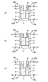
- FIG. 2 is a schematic diagram for explaining the operation of the liquid supply system according to the embodiment of the present invention.
- FIG. 2A is a view showing the inside of the second container 12 in a state in which the bellows 41 and 42 are not displaced in either the extending direction or the contracting direction.
- FIG. 2B the liquid L is sucked from the return passage (first passage) K2 into the first pump chamber P1, and the liquid L is sent from the second pump chamber P2 to the supply passage (second passage) K1.
- FIG. 3 The upper part of FIG. 3 is a diagram schematically showing the fluctuation of the pressure applied to the second bellows 42 of the liquid supply system according to the first embodiment, and the lower part of FIG. 3 is the outline of the fluctuation of the pressure applied to the first bellows 41.
- the sealed space R1 is a vacuum space. Therefore, the pressure applied to the second bellows 42 of the liquid supply system 10 according to the present embodiment is zero and the maximum discharge pressure (P discharge) as shown in FIG. It fluctuates so that it goes back and forth between.
- the pressure fluctuation when the maximum discharge pressure (P discharge) is 1 MPa is shown. 3, (a) corresponds to the displacement position of the shaft 15 in FIG.
- the pressure applied to the bellows 41 and 42 is a differential pressure between the pressure outside the bellows and the pressure inside the bellows, and the liquid is not sucked or discharged into the pump chamber without the displacement of the shaft 15 before the start of the apparatus. Since there is no difference between the external pressure and the internal pressure of the bellows 41 and 42, the pressure applied to the bellows is 0 and approaches the state of (b) (the first pump chamber P1 discharges and the second pump chamber P2 sucks).
- the pressure applied to the second bellows 42 increases, and when the outside of the bellows reaches the maximum discharge pressure (P discharge), the pressure applied to the second bellows 42 reaches the maximum (P discharge). Further, as the state approaches (c) (the first pump chamber P1 sucks and the second pump chamber P2 discharges), the pressure applied to the second bellows 42 decreases, and the suction pressure is 0. The pressure applied to the second bellows 42 becomes zero. Note that this pressure fluctuation also exhibits the same behavior with only the first bellows 41 having a different phase.
- the liquid L is supplied to the cooled device 30 through the supply passage K1 by repeating the reciprocating movement of the shaft 15 and the expansion and contraction of each bellows. Further, the liquid L is configured to return to the liquid supply system 10 by the amount supplied to the apparatus to be cooled 30 through the return path K2 connecting the liquid supply system 10 and the apparatus to be cooled 30.
- a cooler 20 that cools the liquid L to an extremely low temperature is provided in the middle of the supply passage K1. With such a configuration, the liquid L cooled to an ultra-low temperature by the cooler 20 circulates between the liquid supply system 10 and the apparatus to be cooled 30.
- the liquid L is sent to the supply passage K1 when each bellows contracts and extends.
- the liquid supply amount by the expansion / contraction operation of each bellows can be doubled compared to, for example, the case where the pump function is exhibited only in the first pump chamber P1. Therefore, compared with the case where the pump function is exhibited only in the first pump chamber P1 with respect to the desired supply amount, the supply amount for one time can be halved, and the maximum pressure of the liquid in the supply passage K1. Can be halved. Therefore, adverse effects due to pressure fluctuations (pulsations) of the supplied liquid can be suppressed.
- the volume of the sealed space R1 formed inside the first bellows 41 and the second bellows 42 does not change even if the first bellows 41 and the second bellows 42 expand and contract (the internal space of the expandable portions of both bellows). Therefore, the internal pressures acting on the first bellows 41 and the second bellows 42 (pressures acting on the respective inner peripheral surfaces) do not change. That is, the liquid supply system 10 according to the present embodiment is configured such that the pump chamber is disposed outside each bellows, and buckling due to fluctuations in the internal pressure of the bellows does not occur. Therefore, it is not necessary to consider internal pressure buckling in the pressure resistance design of the bellows, so that the degree of freedom in design can be increased and the discharge pressure can be increased. Advantages of this embodiment will be described with reference to FIGS. 5 and 6 in comparison with the conventional example.
- FIG. 5 is a schematic diagram for explaining the operation of the liquid supply system according to the conventional example.
- two pump chambers P1 and P2 are formed inside and outside the bellows 61, respectively. That is, when the bellows 61 and 62 contract due to the movement of the shaft 15 (FIG. 2 (a) ⁇ FIG. 2 (b)), the liquid L enters the supply passage K1 from the second pump chamber P2 via the second delivery port 24. The liquid L is delivered and sucked into the first pump chamber P1 through the first suction port 21.
- the bellows 61 and 62 are extended by the movement of the shaft 15 (FIG. 2 (b) ⁇ FIG. 2 (a) ⁇ FIG. 2 (c))
- the liquid L flows through the second suction port 23 into the second pump chamber P2.
- the liquid L is sucked into the first pump chamber P1 and supplied from the first pump chamber P1 to the supply passage K1.
- FIG. 6 is a diagram showing fluctuations in the discharge pressure of the liquid supply system according to the conventional example.
- the pressure applied in the outward direction of the bellows 61 is positive, and the pressure applied in the inward direction of the bellows 61 is negative (the pressure when no liquid is discharged from the pump chamber is ignored for convenience of explanation).
- the pressure applied in the inward direction of the bellows 61 is negative (the pressure when no liquid is discharged from the pump chamber is ignored for convenience of explanation).
- the pressure applied in the outward direction of the bellows 61 is positive, and the pressure applied in the inward direction of the bellows 61 is negative (the pressure when no liquid is discharged from the pump chamber is ignored for convenience of explanation).
- FIG. 6 in the configuration of the conventional example, when the liquid L is alternately discharged from the first pump chamber P1 and the second pump chamber P1, the discharge of the same size is alternately performed inside and outside the bellows 61, respectively. Pressure (P discharge) will act. That is, the discharge pressure (P discharge
- the pressure fluctuation is twice that of the present embodiment (FIGS. 3 and 6). Therefore, the pressure resistance required for the bellows 61 is also twice that of the bellows of the present embodiment.
- the conventional example has a configuration in which the internal pressure acts on the bellows 61. Therefore, if an attempt is made to increase the discharge pressure, the internal pressure acting on the bellows 61 also increases, and the bellows 61 is likely to buckle. End up. In general, a bellows is strong against an external pressure but weak against an internal pressure, and is likely to buckle when a high internal pressure acts.
- the pressure acting on each bellows is only the external pressure, so that the pump discharge pressure can be increased as compared with the conventional configuration in which the internal pressure acts on the bellows.
- the stability of the expansion and contraction operation of the bellows can be improved. Therefore, the number of circulators arranged on the cable can be reduced.
- the degree of freedom of cable laying is improved.
- the second container 12 is surrounded by the first container 11 in a vacuum space. Therefore, since the vacuum space surrounding the second container 12 exhibits a function of hindering heat transfer, heat generated from the linear actuator 14 and atmospheric heat can be prevented from being transmitted to the liquid L. That is, the heat exchange of the liquid L is limited to the heat radiation from the wall surface of the first container 11 which is a vacuum heat insulating container and the heat transfer through the support member 51 and each passage of the second container 12. Intrusion heat can be reduced. Moreover, even if heat is transmitted to the liquid L and vaporizes, the new liquid L is always supplied and has a cooling effect, and therefore, it is possible to suppress the temperature rising to the temperature at which the liquid L evaporates in the pump chamber. Therefore, the pump function is not lowered.
- the shaft 15 is inserted into the second container 12 through the end 43a opposite to the end 43b fixed to the second container 12 in the third bellows 43, and each bellows.
- the third bellows 43 is configured to expand and contract as the shaft 15 reciprocates. Accordingly, the pump chambers P1, P2 and the sealed space R1 are formed without forming a sliding portion between the shaft 15 and the second container 12, so that heat is generated due to frictional resistance due to sliding. It never happens.
- the third bellows 43 is arranged such that the outer diameter is smaller than the inner diameter of the second bellows 42 and at least part of the third bellows 43 enters the inside of the second bellows 42. Since it can be used, it is not necessary to enlarge the space, and the size of the second container 12 can be reduced.
- the sealed space R1 is a vacuum space, it may be configured to communicate with the vacuum space around the second container 12.
- the sealed space R1 is a vacuum space, but a configuration in which the sealed space R1 is filled with gas may be employed.
- the gas sealed in the sealed space R1 for example, a gas that does not easily change its state such as liquefaction or freezing in the usage environment of the system, such as neon gas or helium gas, is used.
- the pressure of the gas sealed in the sealed space R1 is set to a range from vacuum ( ⁇ 100 kPa) to a desired discharge pressure (preferably 1/2 of the discharge pressure).
- FIG. 4 is a diagram schematically showing fluctuations in the discharge pressure of the liquid supply system according to the modification, in which the upper stage shows the pressure fluctuations applied to the second bellows 42, and the lower stage shows the pressure fluctuations applied to the first bellows 41.
- FIG. 4 shows fluctuations in the discharge pressure when a gas having a pressure half that of the discharge pressure (P discharge) is sealed in the sealed space R1 (the pressure when no liquid is discharged from the pump chamber is described). Ignored for convenience).
- the fluctuation range of the discharge pressure is 1 MPa, which is the same as in the first embodiment, but the peak value is 1 ⁇ 2 of that in the first embodiment.
- the pressure applied to the bellows is a differential pressure between the internal pressure of the sealed space R1 and the spaces of the pump chambers P1 and P2, when a gas having a pressure half the discharge pressure is sealed in the sealed space R1, the bellows Since the maximum pressure in the pump chamber is P discharge, From P discharge- (1/2) P discharge to (1/2) P discharge.
- the pressure in the sealed space R1 can be set as appropriate according to the specifications, such as not only the (1/2) P discharge, but also the size of the two bellows and the size of the two pump chambers.
- the peak value of the pressure acting on the bellows 41 and 42 can be reduced by pressurizing the inside of the bellows 41 and 42 with the sealed gas. Therefore, the design freedom in the high pressure design for increasing the pump discharge pressure can be increased.
- FIG. 7 is a schematic diagram showing a liquid contact region in the liquid supply system according to the embodiment of the present invention.
- FIG. 8 is a schematic diagram illustrating a resin coating region in the liquid supply system according to the embodiment of the present invention.
- a hatched area is a distribution area of the liquid L in the liquid supply system 10 according to the present embodiment.
- a region indicated by a thick line is a liquid contact region (resin coating region C) with the liquid L in the liquid supply system 10 according to the present embodiment.
- the liquid supply system 10 is characterized in that a liquid contact portion in each component of the system is coated with a resin.
- a resin that can exhibit wear resistance even in an ultra-low temperature environment, that is, a resin having a low temperature embrittlement temperature lower than the system operating temperature is adopted.
- examples thereof include PTFE (polytetrafluoroethylene) and polyimide.
- Locations coated with the resin include the outer peripheral surfaces of the bellows portions of the first to third bellows 41 to 43 and the entire inner wall surface of the second container 12, the suction ports 21 and 23, the delivery ports 22, 24, the supply passage K1, the return passage K2, the liquid contact surfaces of the check valves 100a to 100d, and the shaft 15, the first flange portion 15a to which the end portion 41a of the first bellows 41 is fixed, the second The second flange portion 15b to which the end portion 42a of the bellows 42 is fixed, the liquid contact surface of the third flange portion 15c to which the end portion 43a of the third bellows 43 is fixed, and the like. Coating is performed by a conventional method such as spraying and applying a resin material to the coating region.
- the coating region is preferably the entire region where there is a possibility of contact with the liquid L, but at least the movable portion in the system, that is, the portion where the relative movement with the liquid L containing the slurry is positively generated in the system. Should be covered.
- the resin that coats the wetted area of the system has a low temperature embrittlement temperature lower than the system operating temperature, so that it can maintain elasticity during use and collides with the liquid L due to relative movement. It can suppress that each structure of a system is damaged by deform
- the bellows are prevented from being damaged by collision between the slurry containing the liquid L and the bellows surface, or by the biting of the slurry into the bellows bellows portion.
- the bellows when the bellows is made of metal, it is more difficult for heat to be transferred to the liquid L than when the metal bellows is in direct contact with the liquid L.
- the temperature rise of the liquid L can be suppressed and maintained at a low temperature.
- the resin coating layer does not need to be in close contact with the coated portion, and in particular, there may be a gap between the metal surface of the bellows. That is, it is only necessary to reduce damage to each component of the system due to contact and collision with the slurry. Therefore, when the entire liquid contact area in the system is resin-coated, the liquid L flows through the resin bag.
- a resin coating is also required on the inner peripheral surface side of the bellows bellows portion, whereas in the pump configuration in this embodiment, the liquid contact portion of the bellows is the bellows bellows portion. Since only the outer peripheral surface is provided, the resin coating may be performed only on the outer peripheral surface of the bellows portion.
Landscapes
- Engineering & Computer Science (AREA)
- Mechanical Engineering (AREA)
- General Engineering & Computer Science (AREA)
- Reciprocating Pumps (AREA)
Abstract
Description
ベローズの伸縮によって、スラリー成分を含む超低温の液体を供給する液体供給システムであって、
前記ベローズにおいて少なくとも前記液体が接触する領域が、低温脆化温度が液体供給システムの使用温度以下の樹脂でコーティングされていることを特徴とする。
なお、超低温の液体としては、液体窒素や液体ヘリウムが挙げられる。
システムの外部と通じる第1通路から液体を吸入し、かつ吸入した液体をシステムの外部と通じる第2通路に送出するように構成された容器と、
前記容器の内部に伸縮方向に直列に配置された第1ベローズ及び第2ベローズであって、互いに近接する側のそれぞれの第1端部がそれぞれ前記容器の内壁に固定され、互いに遠い側のそれぞれの第2端部がそれぞれ伸縮方向に移動可能に構成された第1ベローズ及び第2ベローズと、
前記容器の内部に挿通されて前記第1ベローズ及び前記第2ベローズの前記第2端部がそれぞれ固定され、駆動源によって前記伸縮方向に往復移動することにより、前記第1ベローズ及び第2ベローズを伸縮させる軸と、
を備える液体供給システムであって、
前記容器内のうち前記第1ベローズの外側は第1ポンプ室となっており、該第1ポンプ室には、前記第1通路から液体を第1ポンプ室内に吸入する第1吸入口、及び吸入した液体を第1ポンプ室内から前記第2通路に送出する第1送出口が設けられ、
前記容器内のうち前記第2ベローズの外側は第2ポンプ室となっており、該第2ポンプ室には、前記第1通路から液体を第2ポンプ室内に吸入する第2吸入口、及び吸入した液体を第2ポンプ室内から前記第2通路に送出する第2送出口が設けられ、
前記第1ベローズ及び第2ベローズの内側は、密閉空間が形成され、
少なくとも前記第1ベローズにおいて前記第1ポンプ室に面する領域及び前記第2ベローズにおいて前記第2ポンプ室に面する領域が、低温脆化温度が液体供給システムの使用温度以下の樹脂でコーティングされているとよい。
前記軸は、前記第3ベローズの内側を挿通されて前記第2端部に連結され、
前記第3ベローズにおいて前記第2ポンプ室に面する領域も、前記樹脂でコーティングされるとよい。
図1を参照して、本発明の実施例に係る液体供給システムについて説明する。図1は、本発明の実施例に係る液体供給システムの概略構成図である。
P吐-(1/2)P吐
から、(1/2)P吐となる。また、密閉空間R1の圧力は(1/2)P吐だけでなく、2つのベローズの大きさ、2つのポンプ室の大小、等、仕様により適宜設定することができる。このように、ベローズ41、42内側に対して、封入気体で加圧することにより、ベローズ41、42に作用する圧力のピーク値を低減することができる。したがって、ポンプ吐出圧を高める高圧設計における設計自由度を高めることができる。
11 第1容器
12 第2容器
21 第1吸入口
22 第1送出口
23 第2吸入口
24 第2送出口
14 リニアアクチュエータ
15 軸
41 第1ベローズ
42 第2ベローズ
43 第3ベローズ
51 支持部材
52 ベローズ
20 冷却機
30 被冷却装置
31 容器
32 超電導ケーブル
K1 供給通路
K2 戻り通路
L 液体
P1 第1ポンプ室
P2 第2ポンプ室
R1 密閉空間
C 樹脂コーティング領域
Claims (5)
- ベローズの伸縮によって、スラリー成分を含む超低温の液体を供給する液体供給システムであって、
前記ベローズにおいて少なくとも前記液体が接触する領域が、低温脆化温度が液体供給システムの使用温度以下の樹脂でコーティングされていることを特徴とする液体供給システム。 - 前記超低温の液体は、液体窒素または液体ヘリウムであることを特徴とする請求項1に記載の液体供給システム。
- システムの外部と通じる第1通路から液体を吸入し、かつ吸入した液体をシステムの外部と通じる第2通路に送出するように構成された容器と、
前記容器の内部に伸縮方向に直列に配置された第1ベローズ及び第2ベローズであって、互いに近接する側のそれぞれの第1端部がそれぞれ前記容器の内壁に固定され、互いに遠い側のそれぞれの第2端部がそれぞれ伸縮方向に移動可能に構成された第1ベローズ及び第2ベローズと、
前記容器の内部に挿通されて前記第1ベローズ及び前記第2ベローズの前記第2端部がそれぞれ固定され、駆動源によって前記伸縮方向に往復移動することにより、前記第1ベローズ及び第2ベローズを伸縮させる軸と、
を備え、
前記容器内のうち前記第1ベローズの外側は第1ポンプ室となっており、該第1ポンプ室には、前記第1通路から液体を第1ポンプ室内に吸入する第1吸入口、及び吸入した液体を第1ポンプ室内から前記第2通路に送出する第1送出口が設けられ、
前記容器内のうち前記第2ベローズの外側は第2ポンプ室となっており、該第2ポンプ室には、前記第1通路から液体を第2ポンプ室内に吸入する第2吸入口、及び吸入した液体を第2ポンプ室内から前記第2通路に送出する第2送出口が設けられ、
前記第1ベローズ及び第2ベローズの内側は、密閉空間が形成され、
少なくとも前記第1ベローズにおいて前記第1ポンプ室に面する領域及び前記第2ベローズにおいて前記第2ポンプ室に面する領域が、低温脆化温度が液体供給システムの使用温度以下の樹脂でコーティングされていることを特徴とする請求項1または2に記載の液体供給システム。 - さらに、少なくとも前記容器内において前記第1ポンプ室及び前記第2ポンプ室に面する領域も、前記樹脂でコーティングされていることを特徴とする請求項3に記載の液体供給システム。
- 前記第2ベローズに対して伸縮方向に直列に配置される第3ベローズであって、外側が前記第2のポンプ室となり、内側が前記容器の外部に開放されるように、一方の端部が前記容器に固定されるとともに、他方の端部が前記第2ベローズの前記第2端部に連結され、前記第2ベローズの伸縮にともなって伸縮する第3ベローズをさらに備え、
前記軸は、前記第3ベローズの内側を挿通されて前記第2端部に連結され、
前記第3ベローズにおいて前記第2ポンプ室に面する領域も、前記樹脂でコーティングされることを特徴とする請求項3または4に記載の液体供給システム。
Priority Applications (5)
| Application Number | Priority Date | Filing Date | Title |
|---|---|---|---|
| JP2016550318A JP6572226B2 (ja) | 2014-09-22 | 2015-09-18 | 液体供給システム |
| KR1020177007349A KR20170042753A (ko) | 2014-09-22 | 2015-09-18 | 액체 공급 시스템 |
| CN201580050015.1A CN106715906B (zh) | 2014-09-22 | 2015-09-18 | 液体供给系统 |
| EP15843832.5A EP3199812B1 (en) | 2014-09-22 | 2015-09-18 | Liquid supply system |
| US15/511,989 US10584692B2 (en) | 2014-09-22 | 2015-09-18 | Liquid supply system |
Applications Claiming Priority (2)
| Application Number | Priority Date | Filing Date | Title |
|---|---|---|---|
| JP2014-192956 | 2014-09-22 | ||
| JP2014192956 | 2014-09-22 |
Publications (1)
| Publication Number | Publication Date |
|---|---|
| WO2016047620A1 true WO2016047620A1 (ja) | 2016-03-31 |
Family
ID=55581145
Family Applications (1)
| Application Number | Title | Priority Date | Filing Date |
|---|---|---|---|
| PCT/JP2015/076750 Ceased WO2016047620A1 (ja) | 2014-09-22 | 2015-09-18 | 液体供給システム |
Country Status (6)
| Country | Link |
|---|---|
| US (1) | US10584692B2 (ja) |
| EP (1) | EP3199812B1 (ja) |
| JP (1) | JP6572226B2 (ja) |
| KR (1) | KR20170042753A (ja) |
| CN (1) | CN106715906B (ja) |
| WO (1) | WO2016047620A1 (ja) |
Cited By (3)
| Publication number | Priority date | Publication date | Assignee | Title |
|---|---|---|---|---|
| WO2018143425A1 (ja) * | 2017-02-03 | 2018-08-09 | イーグル工業株式会社 | 断熱構造及び液体供給システム |
| WO2018143422A1 (ja) * | 2017-02-03 | 2018-08-09 | イーグル工業株式会社 | 液体供給システム |
| WO2018143421A1 (ja) * | 2017-02-03 | 2018-08-09 | イーグル工業株式会社 | 液体供給システム |
Families Citing this family (6)
| Publication number | Priority date | Publication date | Assignee | Title |
|---|---|---|---|---|
| USD893678S1 (en) | 2018-02-05 | 2020-08-18 | Blacoh Fluid Controls, Inc. | Valve |
| US10955079B2 (en) | 2018-03-01 | 2021-03-23 | Blacoh Fluid Controls, Inc. | Industrial flow and pressure stabilizer system |
| KR102136007B1 (ko) | 2018-10-22 | 2020-07-21 | 이덕재 | 질량감지수단을 이용한 액체질소 자동 공급장치 및 공급방법 |
| JP6781795B2 (ja) * | 2019-04-09 | 2020-11-04 | 株式会社Ihi回転機械エンジニアリング | 往復動圧縮機 |
| US11346374B2 (en) | 2020-09-08 | 2022-05-31 | Blacoh Fluid Controls, Inc. | Fluid pulsation dampeners |
| US11549523B2 (en) | 2021-04-27 | 2023-01-10 | Blacoh Fluid Controls, Inc. | Automatic fluid pump inlet stabilizers and vacuum regulators |
Citations (6)
| Publication number | Priority date | Publication date | Assignee | Title |
|---|---|---|---|---|
| US4365942A (en) * | 1980-01-29 | 1982-12-28 | Kernforschungszentrum Karlsruhe Gmbh | Liquid helium pump |
| JPS58158173U (ja) * | 1982-04-17 | 1983-10-21 | 日本フイ−ダ−工業株式会社 | 往復動ポンプ |
| JPS6336068A (ja) * | 1986-06-28 | 1988-02-16 | ドイチェ フォルシュングスアンシュタルト フュア ルフトーウント ラウムファールト エー.ファウ | 極低温流体用ピストンポンプ |
| JPS6453078A (en) * | 1987-08-18 | 1989-03-01 | Japan Res Dev Corp | Fluid compressor |
| JPH0689745B2 (ja) * | 1986-08-28 | 1994-11-14 | 日本ピラ−工業株式会社 | 液中浸漬エア駆動形ポンプ |
| WO2012124363A1 (ja) * | 2011-03-15 | 2012-09-20 | イーグル工業株式会社 | 液体供給システム |
Family Cites Families (19)
| Publication number | Priority date | Publication date | Assignee | Title |
|---|---|---|---|---|
| US2496711A (en) * | 1946-11-02 | 1950-02-07 | Daniel And Florence Guggenheim | Pumping apparatus for very cold liquids |
| US2613610A (en) * | 1949-02-04 | 1952-10-14 | Milton Roy Co | Differential bellows pump |
| US3456595A (en) * | 1966-09-20 | 1969-07-22 | Union Carbide Corp | Cryogenic liquid metering pump |
| DE1653445A1 (de) * | 1967-06-14 | 1971-07-22 | Erich Goldbecker | Doppeltwirkende Pumpe |
| CH545916A (ja) * | 1971-11-09 | 1974-02-15 | ||
| JPS61246559A (ja) * | 1985-04-20 | 1986-11-01 | 科学技術庁長官官房会計課長 | 流体の圧縮又は膨張機 |
| JPS6236266U (ja) | 1985-08-21 | 1987-03-03 | ||
| US4836756A (en) * | 1986-08-28 | 1989-06-06 | Nippon Pillar Packing Co., Ltd. | Pneumatic pumping device |
| EP0438428B1 (de) | 1988-10-06 | 1992-09-16 | MEINZ, Hans Willi | Doppeltwirkende faltenbalgpumpe |
| US5308230A (en) | 1993-03-08 | 1994-05-03 | Stainless Steel Products, Inc. | Bellows pump |
| WO2000074120A1 (en) * | 1999-05-28 | 2000-12-07 | Nikon Corporation | Exposure method and apparatus |
| JP3761754B2 (ja) | 1999-11-29 | 2006-03-29 | 日本ピラー工業株式会社 | ポンプ、アキュムレータ等の流体機器 |
| US20030226615A1 (en) * | 2002-06-10 | 2003-12-11 | Allen Todd Renell | Liquid dispensing system and method including same |
| DE102006054268A1 (de) * | 2006-11-17 | 2008-05-21 | Veritas Ag | Rohrförmiges Formteil |
| JP4886552B2 (ja) * | 2007-02-28 | 2012-02-29 | 株式会社Ihi | 超電導コイルの冷却装置およびこれに用いる通気板 |
| US9518577B2 (en) * | 2008-06-27 | 2016-12-13 | Lynntech, Inc. | Apparatus for pumping a fluid |
| KR20110057910A (ko) | 2009-11-25 | 2011-06-01 | 윌로펌프 주식회사 | 전수로형 펌프 |
| WO2014091866A1 (ja) * | 2012-12-14 | 2014-06-19 | イーグル工業株式会社 | 液体供給システム |
| KR101885017B1 (ko) * | 2014-07-10 | 2018-08-02 | 이글 고오교 가부시키가이샤 | 액체 공급 시스템 |
-
2015
- 2015-09-18 EP EP15843832.5A patent/EP3199812B1/en active Active
- 2015-09-18 CN CN201580050015.1A patent/CN106715906B/zh active Active
- 2015-09-18 KR KR1020177007349A patent/KR20170042753A/ko not_active Ceased
- 2015-09-18 WO PCT/JP2015/076750 patent/WO2016047620A1/ja not_active Ceased
- 2015-09-18 US US15/511,989 patent/US10584692B2/en not_active Expired - Fee Related
- 2015-09-18 JP JP2016550318A patent/JP6572226B2/ja active Active
Patent Citations (6)
| Publication number | Priority date | Publication date | Assignee | Title |
|---|---|---|---|---|
| US4365942A (en) * | 1980-01-29 | 1982-12-28 | Kernforschungszentrum Karlsruhe Gmbh | Liquid helium pump |
| JPS58158173U (ja) * | 1982-04-17 | 1983-10-21 | 日本フイ−ダ−工業株式会社 | 往復動ポンプ |
| JPS6336068A (ja) * | 1986-06-28 | 1988-02-16 | ドイチェ フォルシュングスアンシュタルト フュア ルフトーウント ラウムファールト エー.ファウ | 極低温流体用ピストンポンプ |
| JPH0689745B2 (ja) * | 1986-08-28 | 1994-11-14 | 日本ピラ−工業株式会社 | 液中浸漬エア駆動形ポンプ |
| JPS6453078A (en) * | 1987-08-18 | 1989-03-01 | Japan Res Dev Corp | Fluid compressor |
| WO2012124363A1 (ja) * | 2011-03-15 | 2012-09-20 | イーグル工業株式会社 | 液体供給システム |
Cited By (7)
| Publication number | Priority date | Publication date | Assignee | Title |
|---|---|---|---|---|
| WO2018143425A1 (ja) * | 2017-02-03 | 2018-08-09 | イーグル工業株式会社 | 断熱構造及び液体供給システム |
| WO2018143422A1 (ja) * | 2017-02-03 | 2018-08-09 | イーグル工業株式会社 | 液体供給システム |
| WO2018143421A1 (ja) * | 2017-02-03 | 2018-08-09 | イーグル工業株式会社 | 液体供給システム |
| CN110192033A (zh) * | 2017-02-03 | 2019-08-30 | 伊格尔工业股份有限公司 | 液体供给系统 |
| CN110192031A (zh) * | 2017-02-03 | 2019-08-30 | 伊格尔工业股份有限公司 | 液体供给系统 |
| RU2724614C1 (ru) * | 2017-02-03 | 2020-06-25 | Игл Индастри Ко., Лтд. | Теплоизоляционная структура и система подачи жидкости |
| US20200232448A1 (en) * | 2017-02-03 | 2020-07-23 | Eagle Industry Co., Ltd. | Liquid supply system |
Also Published As
| Publication number | Publication date |
|---|---|
| KR20170042753A (ko) | 2017-04-19 |
| CN106715906B (zh) | 2019-06-07 |
| US20170298914A1 (en) | 2017-10-19 |
| JPWO2016047620A1 (ja) | 2017-07-06 |
| US10584692B2 (en) | 2020-03-10 |
| JP6572226B2 (ja) | 2019-09-04 |
| EP3199812A4 (en) | 2018-04-18 |
| EP3199812B1 (en) | 2019-06-19 |
| EP3199812A1 (en) | 2017-08-02 |
| CN106715906A (zh) | 2017-05-24 |
Similar Documents
| Publication | Publication Date | Title |
|---|---|---|
| JP6572226B2 (ja) | 液体供給システム | |
| JP6457517B2 (ja) | 液体供給システム | |
| JP5844348B2 (ja) | 液体供給システム | |
| US6746212B2 (en) | High efficiency pump for liquid-cooling of electronics | |
| CN100540894C (zh) | 线性压缩机 | |
| JP6209160B2 (ja) | 圧縮機デバイス、圧縮機デバイスを備える冷却デバイス、および圧縮機デバイスを備える冷却ユニット | |
| US10415560B2 (en) | Dual-head, pulseless peristaltic-type metering pump | |
| JP2014526012A5 (ja) | ||
| CN105715625B (zh) | 液压缸单元 | |
| US20120297800A1 (en) | Supersonic Cooling Nozzle Inlet | |
| JP2025534933A (ja) | 高圧再循環熱ポンプの無摩擦設計 | |
| EP3480460B1 (en) | Volumetric pump | |
| US20200232448A1 (en) | Liquid supply system | |
| CN110177943A (zh) | 液体供给系统 | |
| US9759459B2 (en) | Regenerator and regenerative refrigerator with insertion member | |
| JP2015137798A (ja) | 極低温冷凍機 | |
| WO2012018627A1 (en) | Supersonic cooling nozzle inlet | |
| CN108350871A (zh) | 气体用泵 | |
| HK1231160B (zh) | 溶液泵系统 |
Legal Events
| Date | Code | Title | Description |
|---|---|---|---|
| 121 | Ep: the epo has been informed by wipo that ep was designated in this application |
Ref document number: 15843832 Country of ref document: EP Kind code of ref document: A1 |
|
| ENP | Entry into the national phase |
Ref document number: 2016550318 Country of ref document: JP Kind code of ref document: A |
|
| WWE | Wipo information: entry into national phase |
Ref document number: 15511989 Country of ref document: US |
|
| ENP | Entry into the national phase |
Ref document number: 20177007349 Country of ref document: KR Kind code of ref document: A |
|
| NENP | Non-entry into the national phase |
Ref country code: DE |
|
| REEP | Request for entry into the european phase |
Ref document number: 2015843832 Country of ref document: EP |
|
| WWE | Wipo information: entry into national phase |
Ref document number: 2015843832 Country of ref document: EP |