WO2016047803A1 - ドリル及びドリルヘッド - Google Patents
ドリル及びドリルヘッド Download PDFInfo
- Publication number
- WO2016047803A1 WO2016047803A1 PCT/JP2015/077325 JP2015077325W WO2016047803A1 WO 2016047803 A1 WO2016047803 A1 WO 2016047803A1 JP 2015077325 W JP2015077325 W JP 2015077325W WO 2016047803 A1 WO2016047803 A1 WO 2016047803A1
- Authority
- WO
- WIPO (PCT)
- Prior art keywords
- drill
- tip
- blade
- tip blade
- axis
- Prior art date
- Legal status (The legal status is an assumption and is not a legal conclusion. Google has not performed a legal analysis and makes no representation as to the accuracy of the status listed.)
- Ceased
Links
Images











Classifications
-
- B—PERFORMING OPERATIONS; TRANSPORTING
- B23—MACHINE TOOLS; METAL-WORKING NOT OTHERWISE PROVIDED FOR
- B23B—TURNING; BORING
- B23B51/00—Tools for drilling machines
Definitions
- the present invention relates to a drill for drilling a work material such as CFRP (carbon fiber reinforced resin) or a composite material in which a metal plate such as titanium or aluminum is laminated on the CFRP, and a blade tip replaceable drill
- the present invention relates to a drill head that is detachably attached to the tip of the tool body or is attached to the tip of the tool body in a fixed state by brazing or the like.
- This application includes Japanese Patent Application No. 2014-197097 filed in Japan on September 26, 2014, Japanese Patent Application No. 2015-150810 filed in Japan on July 30, 2015, and September 24, 2015. Claims priority based on Japanese Patent Application No. 2015-187316 filed in Japan, the contents of which are incorporated herein by reference.
- CFRP carbon fiber reinforced resin
- a work material such as a composite material in which a metal plate such as titanium or aluminum is laminated on the CFRP has been drilled. It has been broken.
- the fiber layer is formed on the inner periphery of the work hole due to the thrust load (force acting from the drill toward the work piece in the drill feed direction) transmitted from the drill during drilling. Delamination is likely to occur. Further, uncut fibers, extensibility burrs, whiskers, etc. (hereinafter abbreviated as burrs) may occur.
- burrs uncut fibers, extensibility burrs, whiskers, etc.
- the drill described in Patent Document 1 reduces the thrust load by setting the tip angle as small as 70 to 100 °.
- the drills described in Patent Documents 2 and 3 are formed with an acute angle so that the tip is pointed when viewed from the side of the drill, and the tip angle of the cutting edge gradually or gradually decreases from the tip toward the base end. The thrust load is reduced.
- a small diameter portion and a large diameter portion that are adjacent to each other in the drill axis direction are formed at the drill tip portion.
- the large-diameter portion is cut into the work material, and the inner periphery of the processing hole is finished. That is, even when a defect such as delamination or burrs occurs due to the drilling of the small diameter part, the large diameter part cut after that cuts out the inner periphery of the processed hole together with the part where the defect occurs.
- the drill described in Patent Document 5 is a so-called candle type drill, and is formed such that the end portion on the radially outer side of the cutting edge (tip blade) protrudes toward the drill tip side.
- the part cuts sharply into the inner periphery of the processed hole, thereby suppressing the occurrence of delamination or burrs.
- the conventional drill has the following problems.
- the drills of Patent Documents 1 to 3 can reduce the thrust load during drilling to suppress delamination, the radial load is increased accordingly. That is, since the drilling process is performed while expanding the processing hole of the work material in the radial direction, a diameter reduction phenomenon (spring back) of the processing hole occurs after the processing, and it is difficult to ensure the hole processing accuracy.
- the inner periphery of the processed hole is pressed radially outward and elastically deformed, restored and deformed after processing, and reduced in diameter than the intended hole diameter. Accuracy cannot be ensured.
- the blade length of the cutting edge is increased, the cutting resistance during drilling is increased.
- the stroke during drilling processing length in the drill feed direction
- the processing efficiency productivity
- the drill of Patent Document 5 is formed such that the radially outer end portion of the cutting edge (tip blade) protrudes toward the drill tip side with respect to a portion other than the end portion. Acts greatly, and wear and defects are likely to occur.
- the present invention has been made in view of the above circumstances, and can improve the quality and inner diameter accuracy of the inner periphery of a drilled hole drilled in a work material, and suppress cutting resistance during drilling.
- An object of the present invention is to provide a drill and a drill head capable of improving machining efficiency, suppressing wear and chipping of a cutting edge, sufficiently securing a re-polishing allowance, and extending a tool life.
- the present invention proposes the following means. That is, the drill of the present invention, a drill body that is rotated around an axis, a chip discharge groove that is formed on the outer periphery of the drill body and extends from the distal end toward the proximal side along the axial direction, A tip blade formed at a crossing ridge line portion between the wall surface of the chip discharge groove facing the drill rotation direction and the tip surface of the drill body, and the tip blade is directed outward in the radial direction perpendicular to the axis. A first tip blade extending toward the base end side in the axial direction; and a second tip blade disposed outside the radial direction of the first tip blade.
- the inner end in the radial direction of the second tip blade is the diameter of the first tip blade. It is arranged on the base end side in the axial direction with respect to the outer end in the direction.
- said radially outer end of the second tip blade is characterized in that it is disposed the first tip blade on a virtual extended line extended outward in the radial direction.
- a drill head mounted on a tip of a tool body, the head body being rotated together with the tool body about an axis, and formed on an outer periphery of the head body so as to be along the axis direction.
- a chip discharge groove extending from the distal end toward the base end side, a tip blade formed at a cross ridge line portion of the wall surface of the chip discharge groove facing the drill rotation direction and the distal end surface of the head body, and
- the tip blade is a first tip blade extending toward the base end side in the axial direction as it goes outward in the radial direction perpendicular to the axis, and a second tip disposed on the radially outer side of the first tip blade.
- a tip blade, and the second tip blade extends toward the tip end side in the axial direction as it goes outward in the radial direction, or extends perpendicularly to the axis.
- the radially inner end of the first tip blade It is arranged on the base end side in the axial direction with respect to the outer end in the radial direction, and the outer end in the radial direction of the second tip blade extends the first tip blade toward the outer side in the radial direction. It is arranged on a virtual extension line.
- the front end blade located on the front end surface of the drill includes the first front end blade and the second front end blade disposed on the radially outer side of the first front end blade.
- the first tip blade is inclined toward the base end side in the axial direction as it goes outward in the radial direction
- the second tip blade is in the axial direction as it goes outward in the radial direction. It inclines toward the front end side or extends perpendicularly to the axis.
- the radially inner end of the second distal blade is disposed closer to the proximal end in the axial direction than the radially outer end of the first distal blade, and the radially outer end of the second distal blade is the first Since it is located on the virtual extension line which extended the front-end
- the tip blade since the tip blade is separately provided with the first tip blade positioned radially inward at the drill tip and the second tip blade positioned radially outside, the first tip blade provides the work material.
- Thrust load generated during drilling is the inner circumference of the machining hole in the workpiece (the inner circumference here refers to machining after machining) It points to the planned part that becomes the inner periphery of the hole, and acts on the portion located inside in the radial direction from the inner peripheral plan part), and this thrust load is applied to the outer peripheral part of the drill (in the work material) Is prevented from propagating to the inner periphery of the machined hole).
- the thrust load acting on the work material during drilling tends to be large at the radially inner part (near the central part in the radial direction including the axis) at the drill tip.
- the delamination was likely to occur because the thrust load acting from the vicinity of the center of the drill tip propagated to the inner peripheral planned portion of the drilled hole.
- the thrust load acting on the work material from the vicinity of the center portion of the drill tip is separated from each other by the first and second tip blades, so that the inner peripheral scheduled portion of the machining hole Therefore, it is possible to suppress the occurrence of delamination on the inner periphery of the processed hole after processing.
- the tip angle of the drill is set to be small or the tip of the drill is set to suppress delamination as in the conventional drill. It is not necessary to form an acute angle so as to sharpen the portion. Therefore, according to the present invention, the blade length of the tip blade can be kept short. Thereby, the cutting resistance at the time of drilling can be suppressed. In addition, the axial length of the tip blade can be kept small, the stroke during drilling (machining length in the drill feed direction) can be kept small, and machining efficiency (productivity) is improved.
- the component force toward the tip side in the axial direction (drill feed direction) out of the cutting force acting on the work material from the first and second tip blades becomes the thrust load, which is directed in the radial direction.
- the component force becomes the radial load.
- tip blade is a radial direction outer side. It is inclined toward the tip end side in the axial direction as it goes to or extends perpendicularly to the axis.
- the direction of the thrust load that acts on the work material from the first and second tip edges is the same as each other, while the direction of the radial load that acts on the work material from the first tip edge and the direction from the second tip edge.
- the directions of radial loads acting on the work material are different from each other. Specifically, the radial load of the first tip edge acts radially outward with respect to the work material, while the radial load of the second tip edge is directed radially inward with respect to the work material. Acts or becomes almost zero (does not act).
- the tip of the drill acts toward the work piece radially outward. Due to the increased radial load, drilling was performed while expanding the processing hole in the radial direction, and after processing, the hole diameter was reduced (spring back), making it difficult to ensure the accuracy of the inner diameter of the processing hole. .
- the radial load acting on the work material from the first tip edge in the radial direction acts on the work material from the second tip edge in a direction different from the radial load. It can be reduced by the load or not increased further.
- the radial load of the entire tip edge of the drill according to the present invention is reduced with respect to the radial load of the entire tip edge of the conventional drill.
- the second tip blade can be disposed near the inner peripheral planned portion of the processing hole of the work material. In this case, a radial load directed radially inward of the second tip blade is applied to the processing hole. It is possible to make it act directly on the inner peripheral scheduled part. Therefore, it is possible to effectively suppress the occurrence of the diameter reduction phenomenon on the inner periphery of the processed hole, and the inner diameter accuracy of the processed hole is improved.
- the second tip edge extends toward the tip end side in the axial direction as it goes outward in the radial direction or perpendicularly to the axis, the second tip edge is near the inner peripheral planned portion of the machining hole. It is made to cut sharply.
- the second tip blade is set in the radial direction. Increasing the radial rake angle (radial rake angle) of the second tip edge more easily than the radial rake angle of the first tip edge by inclining gradually toward the base end side in the axial direction from the outer end toward the inner side.
- the first and second tip edges are substantially simultaneously cut during drilling. Will cut into. Therefore, during drilling, excessive cutting resistance does not act on the second tip blade, and the above-described configuration sufficiently increases the sharpness of the second tip blade, Defects can be suppressed.
- the first and second tip blades are arranged to be separated from each other in the axial direction. Nor. Therefore, the above-described effect that the stroke at the time of drilling can be kept small can be surely obtained.
- the outer end in the radial direction of the second tip blade is located on the virtual extension line of the first tip blade, for example, a concave portion is formed on a part of the blade length of the entire tip blade.
- the first and second tip edges can be easily formed. Therefore, manufacture of a drill is easy.
- the outer end in the radial direction of the second tip blade is located on the virtual extension line of the first tip blade, it is easy to ensure a large re-polishing allowance for the tip blade. Therefore, the tool life can be extended.
- the quality and inner diameter accuracy of the inner periphery of the machining hole drilled in the work material can be improved, the cutting resistance during drilling can be suppressed, the machining efficiency can be improved, and the cutting edge can be improved.
- wear and chipping can be suppressed, a sufficient amount of re-polishing can be secured, and the tool life can be extended.
- the tip blade has a third tip blade disposed on the radially outer side of the second tip blade, and the third tip blade extends along the virtual extension line. It may be extended.
- the third tip blade is cut into the work material almost simultaneously with the first and second tip blades.
- the quality of the inner periphery of the machining hole and the accuracy of the inner diameter can be improved.
- the third tip blade is provided between the radial outer end of the second tip blade and the tip (leading edge) of the outer peripheral blade extending along the chip discharge groove, It is possible to prevent the formation of a sharp corner between the tip blade and the outer peripheral blade, and it is possible to connect them with an obtuse corner. That is, since the strength of the blade edge can be sufficiently increased at the connection portion between the tip blade and the outer peripheral blade, wear and chipping of the cutting blade are remarkably suppressed.
- the radially inner end of the second tip blade is located on the inner side in the radial direction or at the same position in the radial direction with respect to the radially outer end of the first tip blade. It is good also as arrange
- the position of the nick must be shifted in the blade length direction between the cutting blades (tip blades) adjacent in the circumferential direction. , Leaving uncut.
- no uncut portion is generated in each of the tip blades adjacent to each other in the circumferential direction, so that the first and second tip blades can be relatively freely arranged at the expected positions. Therefore, it is possible to easily respond to various requests for drills.
- adopted the said structure of this invention can exhibit an especially remarkable effect, especially when drilling CFRP as a work material.
- a ridge line connecting the radially outer end of the first tip blade and the radially inner end of the second tip blade is formed, and the drill body is connected to the diameter. It is preferable that an angle ⁇ 1 formed between the axis and the ridge line in a side view as viewed from the direction is 10 ° or less.
- the acute angle ⁇ 1 of the acute angle and the obtuse angle formed between the axis and the ridge line is 10 ° or less in the side view of the drill, the following effects are obtained. That is, while preventing the uncut portion from being generated between the first and second tip blades, the tip of the drill is formed by notching a large concave portion radially inward in forming the second tip blade. It is possible to prevent the rigidity of the steel from being lowered.
- an inner end in the radial direction of the second tip blade is disposed on an outer side in the radial direction with respect to an outer end in the radial direction of the first tip blade, and the tip blade Is connected to the radially outer end of the first tip blade and the radially inner end of the second tip blade, and toward the proximal end side in the axial direction as it goes outward in the radial direction. It is good also as having the 4th tip edge extended.
- the 4th tip blade which connects these is arranged between the 1st tip blade and the 2nd tip blade, the thing which remains uncut between the 1st and 2nd tip blades may arise. Is more reliably prevented. Therefore, for example, when applying the above-described configuration of the present invention to a multi-blade drill such as a two-blade or a three-blade, between the cutting blades (tip blades) adjacent in the circumferential direction, It is not necessary to shift the separation position (position where the fourth tip blade is disposed) from each other in the blade length direction.
- the drill adopting the above-described configuration of the present invention is a composite material in which a metal plate such as titanium or aluminum is laminated on CFRP (in particular, a metal plate is disposed at the end on the drill penetration side) as a work material. In the case of drilling a highly extensible metal material or the like, a particularly remarkable effect can be exhibited.
- an angle ⁇ 2 formed between the axis and the fourth tip blade may be 30 ° or less in a side view when the drill body is viewed from the radial direction. .
- the acute angle ⁇ 2 is 30 ° or less among the acute angle and the obtuse angle formed between the axis and the fourth tip edge in a side view of the drill, the following effects are obtained. That is, since the angle ⁇ 2 is set to 30 ° or less, the fourth tip blade extends substantially along the axis without being greatly inclined with respect to the axis, and the blade length of the fourth tip blade is shortened. can do. Thereby, the blade length of the 2nd tip edge can be lengthened, and the effect by having provided the 2nd tip edge mentioned above becomes more remarkable.
- the tip of the drill corresponding to a double angle of an acute angle formed between the first tip blade and the axis in a side view when the drill body is viewed from the radial direction.
- the angle ⁇ is preferably 100 ° or more and 170 ° or less.
- the tip angle ⁇ of the drill is 100 ° or more, the tip angle ⁇ does not become too small, and a radial load (a force acting radially outward on the work material during drilling) ) Is prevented from becoming excessive. Thereby, the effect which suppresses the diameter reduction phenomenon of the processed hole after a process becomes further remarkable. Further, since the tip angle ⁇ of the drill is 170 ° or less, the tip angle ⁇ does not become too large, and a thrust load (force acting in the drill feed direction with respect to the work material) is generated during drilling. It is prevented that it becomes excessive. Thereby, the effect which suppresses delamination becomes still more reliable.
- the diameter of the rotation locus obtained by rotating the tip blade in the circumferential direction around the axis is ⁇ D
- the radially outer end of the second tip blade is the tip of the tip blade. It is preferable to arrange in the range of ⁇ D ⁇ 10% or less from the outer end in the radial direction.
- the second tip blade can be arranged near the planned inner periphery of the machining hole of the work material, and the radial load directed radially inward of the second tip blade is planned to be the inner periphery of the machining hole. It can act directly on the part. Therefore, it is possible to more effectively suppress the occurrence of the diameter reduction phenomenon on the inner periphery of the processed hole, and the inner diameter accuracy of the processed hole is improved.
- the second tip edge extends toward the tip end side in the axial direction as it goes outward in the radial direction or perpendicularly to the axis, the second tip edge is near the inner peripheral planned portion of the machining hole. It will cut sharply. Accordingly, the occurrence of burrs or the like on the inner periphery of the processed hole can be more effectively suppressed, and the quality of the inner periphery of the processed hole can be improved.
- the diameter of the rotation locus obtained by rotating the tip blade in the circumferential direction around the axis is ⁇ D
- the radially outer end of the first tip blade is the tip edge of the tip blade. It is preferable to arrange in the range of ⁇ D ⁇ 25% or less from the outer end in the radial direction.
- the outer end in the radial direction of the first tip blade is disposed in a range of ⁇ D ⁇ 25% or less from the outermost end in the radial direction as the entire tip blade, the following effects are produced. That is, the blade length of the first tip blade can be secured approximately half or more than the blade length of the entire tip blade, and a second tip blade is formed that is disposed radially outside the first tip blade. In doing so, it is possible to prevent the rigidity of the drill tip from being lowered by cutting out a large recess.
- an angle ⁇ formed between a virtual plane perpendicular to the axis and the second tip blade in a side view of the drill body viewed from the radial direction is 25 ° or less. Preferably there is.
- the acute angle ⁇ of the acute angle and the obtuse angle formed between the virtual plane perpendicular to the axis and the second tip edge in a side view of the drill is 25 ° or less, and the following effects are obtained. That is, the axial position at the radially inner end of the second tip blade is prevented from being largely separated from the first tip blade toward the proximal end side in the axial direction. Thereby, in forming the second tip blade, it is prevented that the rigidity of the drill tip is lowered by cutting out a large recess or the like. In addition, the effect of reducing the stroke during drilling is further ensured.
- a gash rake face is formed in a wall surface of the chip discharge groove facing the drill rotation direction and connected to the tip surface via the tip blade so as to be parallel to the axis.
- the tip blade extends in a radial direction perpendicular to the axis in a front view of the drill when the drill body is viewed from the tip in the axial direction toward the base end.
- the tip portion connected to the tip surface via the tip blade has a gash rake face parallel to the axis.
- the distal end blade extends along a radial direction perpendicular to the axial line. preferable.
- the gash rake face of the chip discharge groove serving as the rake face of the tip edge is formed so as to be parallel to the axis of the drill body, the axial rake angle (axial rake angle) of the tip edge is Negative angle (0 °).
- tip blade is extended so that the radial direction of a drill main body may be met. In other words, the tip blade is set to have a core height of zero that is neither raised nor lowered.
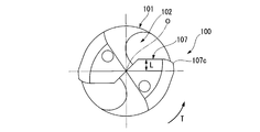
- the core height is a distance at which the tip blade is separated from a virtual straight line passing through the axis parallel to the blade length direction of the tip blade in a front view of the drill.
- the distance L by which the tip blade 107 is separated from the virtual straight line passing through the axis O and parallel to the blade length direction of the tip blade 107. Is the core height.
- the drills 100 and 110 are a drill body 101 that is rotated around an axis O, a chip discharge groove 102 that is formed on the outer periphery of the drill body 101 and extends from the distal end toward the proximal end along the axis O direction, A tip blade 107 formed at a crossing ridge line portion between the wall surface of the chip discharge groove 102 facing the drill rotation direction T and the tip surface of the drill main body 101.
- the radial edge of the tip blade 107 (outer periphery corner) 107 c is closely related to the finishing accuracy of the inner periphery of the drilled hole.
- the chip discharge groove 102 opens to the distal end surface of the drill body 101 and gradually increases from the distal end surface toward the proximal end side in the axis O direction. It twists toward the opposite side of the drill rotation direction T and extends in a spiral shape. For this reason, the axial rake angle (axial rake angle) of the tip blade 107 is a positive angle. In addition, as shown in FIG. 30, the radial rake angle (radial rake angle) R of the outer peripheral corner 107c of the tip blade 107 is a positive angle (+).
- the inner circumference of the machining hole of the workpiece W shown in FIG. Etc. are likely to occur. That is, the work material W made of CFRP or the like has fiber orientation, and in FIG. 33, the fiber orientation is the vertical direction (longitudinal direction). For this reason, when the radial rake angle R of the outer peripheral corner 107c of the tip blade 107 is a positive angle (+), the cutting edge is cut into an acute angle in the region A of the inner periphery of the processing hole (the cutting edge is a fiber streak). In contrast, the fiber is easily peeled off and the burrs are generated.
- the axial rake angle of the tip blade 107 is a negative angle (0 °).
- the radial rake angle R of the outer peripheral corner 107c of the tip blade 107 is a negative angle ( ⁇ ) that is larger on the negative angle side than 0 °.
- the tip blade extends along the radial direction when viewed from the front of the drill, and the core height is substantially zero.
- the tip blade extends along the radial direction means that, in a front view of the drill, a virtual straight line passing through the outer end (outer peripheral corner) and the axis of the tip blade in the radial direction, and the blade length of the tip blade
- the angle formed between the two directions is a small value close to zero (approximately 0 °). Specifically, the angle is, for example, 5 ° or less (0 to 5 °). .
- the axial rake angle of the leading edge is a negative angle (0 °) and the leading edge extends along the radial direction (the center height is zero), the outer peripheral corner of the leading edge
- the radial rake angle is a negative angle (0 °). Therefore, when a work material such as CFRP is drilled by the drill and the drill head having the above-described configuration according to the present invention, the region indicated by the symbol A in the inner periphery of the work hole of the work material W shown in FIG. In both the (circumferential region) and the region indicated by the symbol B (circumferential region), the occurrence of burrs or the like is significantly suppressed.
- the cutting edge is conventionally cut at an acute angle (the cutting edge is cut sharply in the opposite direction with respect to the fiber streak), and the fiber is peeled off.
- the cutting edge since a blade edge cuts at right angle, it is suppressed that a fiber is peeled off.
- the cutting edge has conventionally been cut at an obtuse angle (the cutting edge is smooth but cut smoothly with respect to the fiber streak), and the fiber is likely to remain uncut.
- the cutting edge has a right angle. Therefore, the occurrence of uncut fiber is suppressed. Therefore, the drill and the drill head having the above-described configuration according to the present invention can suppress the occurrence of burrs or the like over the entire circumferential direction of the inner periphery of the processed hole.
- a portion of the chip discharge groove that is located closer to the base end side in the axial direction than the gash rake face gradually moves toward the base end side in the axial direction from the gash rake face. It is good also as extending twisted toward the opposite side to a drill rotation direction.
- the chip discharge groove is a torsion groove extending spirally on the outer periphery of the drill body. Therefore, the chip discharging property is maintained well.
- the chip discharge groove may extend in parallel to the axis.
- the chip discharge groove is a straight groove extending linearly on the outer periphery of the drill body. Therefore, it is easy to form the chip discharge groove at the time of drill manufacture.
- the distal end surface extends from at least the second distal end of the distal end toward the opposite side of the drill rotation direction and is recessed toward the proximal end in the axial direction.
- a recess is formed in the drill body, and a coolant hole that penetrates the drill body in the axial direction is formed in the drill body, and at least a part of the coolant hole that opens in the tip surface is formed in the recess.
- the distal end surface may extend from at least the second distal end of the distal end blade toward the side opposite to the drill rotation direction and toward the proximal end in the axial direction.
- a recess is formed so as to be recessed, and a coolant hole that penetrates the head body in the axial direction is formed inside the head body, and at least a part of the coolant hole that opens in the tip end surface is formed in the recess. It is preferable to arrange
- the coolant compressed air or oily or water-soluble cutting fluid
- the coolant hole into the recesses is caused by centrifugal force during drilling, etc., from the recess to the second tip blade and its radially outer side. It is easy to flow stably to the tip edge part (outer peripheral corner, etc.) located at the tip, the tip of the outer peripheral edge (leading edge), and the like.
- the cutting blades (tip blades and outer peripheral blades) flow through the recesses from the tip surface (tip flank surface) to the chip discharge groove (rake face) adjacent to the tip surface in the drill rotation direction. As well as the vicinity thereof. That is, the coolant reaches the cutting edge from the tip surface without being affected by the chips flowing on the rake face. This effectively cools the cutting edge and the vicinity of the inner periphery (machined portion) of the machining hole of the work material, and can significantly improve the machining accuracy.
- the coolant after the coolant has flowed out of the coolant hole that opens in the tip surface of the drill, the coolant flows in an unstable manner without determining the direction of the flow, and the tip surface is positioned on the opposite side of the drill rotation direction. It was supplied to the cutting blade through the inside of the chip discharge groove or the outer peripheral surface of the drill. For this reason, the amount of useless coolant that does not reach the vicinity of the cutting edge increases, and a sufficient cooling effect cannot be obtained. In addition, it is difficult to improve the chip dischargeability in the chip discharge groove.
- the temperature of the processed portion rises due to cutting heat and the CFRP becomes brittle, so that burrs and interlayers are formed. Peeling (delamination) is likely to occur.
- the chips staying in the processed portion cause the bited chips to rub the inner periphery of the processing hole and damage the processing surface, thereby reducing the processing quality.
- the coolant flows without waste from a position close to the cutting edge into the chip discharge groove adjacent to the drill rotation direction through the recess of the tip surface.
- a coolant is stably supplied to the said process part, the temperature rise of this process part can be suppressed notably, and process quality can be improved stably.
- the coolant flows stably to the processing site, it is possible to suppress the retention of chips in the processing site, and to remarkably prevent deterioration of the processing quality due to the biting of the chips. Further, it is possible to effectively suppress the wear and damage of the outer peripheral corner of the tip blade and the leading edge of the outer peripheral blade, which tend to increase the cutting load, and to maintain good cutting performance for a long time.
- the drill of this invention WHEREIN: It is preferable that the said recessed part is each extended toward the opposite side to the drill rotation direction and the drill rotation direction from the opening part of the said coolant hole.
- the drill head of this invention WHEREIN: It is preferable that the said recessed part is each extended toward the opposite side to the drill rotation direction and the drill rotation direction from the opening part of the said coolant hole.
- the recess extends in the drill rotation direction from the opening of the coolant hole, the coolant flowing in the recess moves from the drill tip surface to the chip discharge groove adjacent to the tip rotation surface in the drill rotation direction. It flows stably and the above-mentioned operational effects become more remarkable.
- the recess extends from the opening of the coolant hole toward the side opposite to the drill rotation direction, the coolant flowing in the recess is discharged from the drill tip surface adjacent to the side opposite to the drill rotation direction. Stable flow into the groove. Thereby, discharge
- the recess has a pair of wall surfaces connected at the deepest portion of the recess and has a V-shaped cross section, and the opening of the coolant hole has the pair of wall surfaces. It is preferable that both are open.
- the recess has a pair of wall surfaces connected at the deepest portion of the recess and has a concave V-shaped cross section, and the opening of the coolant hole has the pair of walls. It is preferable that both walls are open.
- the coolant hole is open to both of the pair of wall surfaces connected at the deepest part of the recess, the coolant flowing out from the coolant hole flows along each of these wall surfaces and is evenly distributed. While being dispersed and forming a stable flow with little unevenness in the recess, it flows out of the recess and is stably supplied to the processing site. Therefore, the above-described operational effect becomes more remarkable.
- the drill and the drill head of the present invention it is possible to improve the quality and inner diameter accuracy of the inner periphery of the drilled hole drilled in the work material, to suppress the cutting resistance during drilling, and to improve the processing efficiency.
- the wear and chipping of the cutting edge can be suppressed, the re-polishing allowance can be sufficiently secured, and the tool life can be extended.
- FIG. 4 is an enlarged side view showing a tip portion of the drill of FIG. 1, and is a view of the tip portion viewed from a direction different from that in FIG. 3. It is a figure which expands and shows the V section of FIG. 3, and is a figure explaining the cutting force (thrust load, radial load) which acts with respect to a cut material from a drill at the time of drilling.
- FIG. 23A It is a side view which shows the modification of the drill which concerns on 3rd Embodiment of this invention. It is a front view which shows the modification of the drill which concerns on 3rd Embodiment of this invention. It is a figure which expands and shows the principal part of the drill of FIG. 23A, and is a figure explaining the cutting force (thrust load, radial load) which acts with respect to a cut material from a drill at the time of drilling. It is a figure explaining the angle, radial direction position, etc. of each component of the drill shown in FIG. 23A and FIG. 23B. It is a side view which shows the drill which concerns on 4th Embodiment of this invention.
- FIG. 29A It is a front view which shows the drill which concerns on 4th Embodiment of this invention. It is a side view which shows the modification of the drill which concerns on 2nd Embodiment of this invention. It is a front view which shows the modification of the drill which concerns on 2nd Embodiment of this invention. It is a front view which shows the modification of the drill which concerns on 3rd Embodiment of this invention. It is a side view which shows the conventional drill. It is a front view which shows the conventional drill. It is a figure which shows the IX-IX cross section of FIG. 29A. It is a side view which shows the conventional drill. It is a front view which shows the conventional drill. FIG.
- FIG. 31B is a diagram showing a XI-XI cross section of FIG. 31A. It is a figure explaining the area
- the drill 10 of the present embodiment has a generally cylindrical shape centering on the axis O, and has a drill body 1 formed of a hard material such as cemented carbide. .
- the drill body 1 has a base end side portion in the axis O direction as a cylindrical shank portion and a tip end portion in the axis O direction as a blade portion having a cutting edge.
- the cutting blade includes a tip blade 7 and an outer peripheral blade 4 which will be described later.
- the drill 10 has a shank portion of the drill body 1 that is detachably mounted on a main spindle of a machine tool, a three-jaw chuck of a drilling machine or an electric drill, and the like, while being rotated in a drill rotation direction T around the axis O. It is sent out to the front end side (the lower side in FIG. 1) along the direction, and cut into the work material by the blade portion to perform drilling.
- the work material include CFRP (carbon fiber reinforced resin) used for aircraft parts and the like, a composite material in which a metal plate such as titanium or aluminum is laminated on the CFRP, or a highly extensible metal. Materials and the like.
- the blade part side (lower side in FIG. 1) along the axis O direction of the drill body 1 is referred to as the tip side, and the shank part side that is gripped by the spindle of the machine tool or the like on the side opposite to the blade part.
- the upper side in FIG. a direction perpendicular to the axis O is referred to as a radial direction, and in this radial direction, a direction approaching the axis O is referred to as a radial inner side, and a direction away from the axis O is referred to as a radial outer side.
- the direction that circulates around the axis O is referred to as the circumferential direction
- the direction in which the drill 10 is rotated at the time of cutting is referred to as the drill rotation direction T
- the direction toward the opposite side is the drill.
- the direction opposite to the rotation direction T (the anti-drill rotation direction) is referred to.
- a chip discharge groove 2 extending from the distal end toward the base end side along the axis O direction, a wall surface 2 a facing the drill rotation direction T of the chip discharge groove 2, and the outer peripheral surface of the drill main body 1 And an outer peripheral blade 4 formed at the intersection ridge line portion.
- the outer peripheral surface of the drill body 1 is connected to the outer peripheral surface other than the chip discharge groove 2 on the side opposite to the drill rotation direction T of the outer peripheral blade 4 and extends along the outer peripheral blade 4.
- the margin part 11 forming the outermost diameter part of the blade part of the drill body 1 and the margin part 11 on the side opposite to the drill rotation direction T, and having a smaller diameter than the outer peripheral blade 4 and the margin part 11. Are formed on the second take-up surface 15.
- a plurality of chip discharge grooves 2 are formed on the outer periphery of the drill body 1 at intervals in the circumferential direction, and each of these chip discharge grooves 2 opens on the tip surface 6 of the drill body 1.
- it gradually twists toward the side opposite to the drill rotation direction T and extends in a spiral shape.
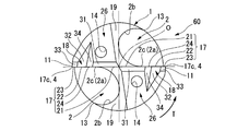
- chip discharge grooves 2 are arranged at equal intervals (equal pitches) in the circumferential direction on the outer periphery of the drill body 1 so as to be rotationally symmetric with respect to the axis O.
- the drill 10 of the present embodiment is a twist drill in which the two chip discharge grooves 2 are arranged in the drill main body 1 in a 180-degree rotational symmetry with respect to the axis O.
- the chip discharge groove 2 opens in the distal end surface 6 of the drill body 1 and extends toward the proximal end side, and near the central portion along the axis O direction of the drill body 1 (in the illustrated example, In the portion located slightly on the base end side from the central portion), the outer peripheral surface is cut out radially outward.
- channel 2 along the axis line O direction was formed is made into a blade part, and the base end side is made into the shank part rather than this range.
- the chip discharge groove 2 is formed so that the inner periphery of the groove has a concave curved surface shape and is recessed toward the radially inner side and the drill rotation direction T. Further, the chip discharge groove 2 is formed so that the groove depth is deepest (the inner periphery of the groove is closest to the axis O) in the vicinity of the central portion along the circumferential direction.
- the outer peripheral blade 4 has a leading edge at the tip in the axis O direction.
- the outer diameter of the blade portion of the drill main body 1 is gradually made slightly smaller from the distal end in the direction of the axis O toward the proximal end side, and a back taper is given.
- the outer diameter of 4 is gradually reduced from the distal end of the drill body 1 toward the proximal end side.
- the present invention is not limited to this, and the back taper may not be provided to the blade portion of the drill body 1.
- the margin portion 11 is connected to the wall surface 2 a facing the drill rotation direction T of the chip discharge groove 2, and the outermost diameter of the tip blade 7 described later (the outer end in the radial direction of the tip blade 7 rotates around the axis O).
- the margin portion 11 is formed so as to be positioned on a virtual cylindrical surface having an outer diameter substantially equal to the diameter ⁇ D of the circle of the rotation locus formed in this manner.
- a cross ridge line portion between the wall surface 2 a of the chip discharge groove 2 facing the drill rotation direction T and the margin portion 11 is the outer peripheral blade 4.
- the chip discharge groove 2 is formed by being spirally twisted as described above. Therefore, the outer peripheral blade 4 and the margin part 11 along the chip discharge groove 2 are also As it goes from the tip end in the direction of the axis O toward the base end side, it gradually twists toward the side opposite to the drill rotation direction T and extends spirally. In other words, the chip discharge groove 2, the outer peripheral edge 4, and the margin portion 11 have the same twist angle (lead, axial tilt angle).
- a portion of the outer peripheral surface of the drill body 1 that is located between the margin portion 11 and the chip discharge groove 2 adjacent to the margin portion 11 on the opposite side to the drill rotation direction T is a second-handed surface. It is set to 15. With respect to the rotation trajectory around the axis O of the outer peripheral blade 4 (virtual circle corresponding to the outer diameter of the shank portion of the drill body 1 shown in FIG. 2), the second picking surface 15 is disposed so as to recede radially inward. Has been.
- the second picking surface 15 is continuous with the drill portion T on the outer peripheral surface of the drill body 1 opposite to the drill rotation direction T, and has an outer diameter smaller than the outer diameter of the margin portion 11. Yes.
- the retreating amount (second reclaiming depth) of the second picking surface 15 directed radially inward from the rotation locus of the outer peripheral blade 4 is constant over the entire circumferential direction.
- the present invention is not limited to this.
- the second picking surface 15 gradually increases in diameter from the rotation locus of the outer peripheral blade 4 toward the opposite side of the drill rotation direction T from the end in the drill rotation direction T. The amount of retreat toward the inside in the direction may be increased.
- the ridge portion 15 and the cross ridge line portion between the wall surface 2 b facing the opposite side to the drill rotation direction T of the chip discharge groove 2 is a heel portion 13.
- the heel portion 13 is pointed toward the opposite side of the drill rotation direction T and has a ridge shape extending along the chip discharge groove 2.
- the tip of the drill body 1 includes a tip surface 6 facing the tip side (drill feed direction) of the drill 10, a wall surface 2 a facing the drill rotation direction T of the chip discharge groove 2, and the tip surface 6. And a thinning portion 9 located between the tip edge 6 and the chip discharge groove 2 adjacent to the tip surface 6 on the side opposite to the drill rotation direction T.
- the tip surface (tip flank surface) 6 is a drill rotation direction from the first tip blade 21 located on the innermost side in the radial direction among first to third tip blades 21 to 23 described later of the tip blade 7.
- the third flank that is located on the outermost side in the radial direction.
- a second flank face 32 that inclines toward the base end side in the direction of the axis O as it goes from the second tip edge 22 toward the opposite side of the drill rotation direction T.
- first to third flank surfaces 31 to 33 are gradually inclined toward the base end side in the direction of the axis O as they go to the opposite side of the drill rotation direction T, so that the first to third tip ends
- the blades 21 to 23 are provided with clearance angles ⁇ 1 to ⁇ 3, respectively.
- the clearance angle ⁇ 1 of the first flank 31 and the clearance angle ⁇ 3 of the third flank 33 are equal to each other.
- the clearance angle ⁇ 2 of the second clearance surface 32 is smaller than the clearance angle ⁇ 1 of the first clearance surface 31 and the clearance angle ⁇ 3 of the third clearance surface 33.
- the clearance angles ⁇ 1 and ⁇ 3 are about 25 °, for example, and the clearance angle ⁇ 2 is about 5 to 15 °, for example.
- the first flank 31 and the third flank 33 are inclined toward the base end side in the axis O direction toward the radially outer side.
- the 2nd flank 32 inclines toward the front end side of the axis line O direction as it goes to radial direction outer side.
- the front end surface 6 is connected to the opposite side to the drill rotation direction T of the front end blade 7, and the first to third flank surfaces 31 to 33 described above are disposed, and the front is formed in a long rectangular shape in the radial direction And a fan-shaped rear portion which is connected to the front portion on the opposite side to the drill rotation direction T and is set to have a larger clearance angle than the front portion.
- the front end surface 6 is not limited to this, and the front end surface 6 and the rear portion may have the same clearance angle, and the front portion and the rear portion may be flush with each other. .
- the distal end surface 6 has a concave portion 8 that extends from the distal end blade 7 toward the opposite side to the drill rotation direction T and is recessed toward the proximal end side in the axis O direction.
- the recess 8 has a groove shape extending from the tip blade 7 toward the side opposite to the drill rotation direction T, and is formed from the front portion to the rear portion of the tip surface 6.
- the recess 8 has a bottom surface facing the tip side in the direction of the axis O and a wall surface facing the outside in the radial direction, and the bottom surface is the second flank 32 described above.
- a coolant hole 14 is opened in the tip surface 6.
- the coolant hole 14 is twisted and extended in the drill body 1 along the chip discharge groove 2 (with a lead substantially equal to the chip discharge groove 2), and penetrates the drill body 1 in the axis O direction.
- coolant compressed air, oily or water-soluble cutting agent supplied from the spindle of the machine tool circulates, and this coolant is used for processing the tip of the drill body 1 and the work material. It is drained to the site.
- the position at which the coolant hole 14 is opened at the distal end portion of the drill body 1 is set to the inner side in the radial direction than the concave portion 8. Moreover, the coolant hole 14 is opened over the front end surface 6 and the thinning surface 9b mentioned later.
- the opening shape of the coolant hole 14 is circular, but is not limited thereto, and may be other polygonal shapes, elliptical shapes, or the like, for example. .
- the tip blade 7 is continuous from the tip portion of the wall surface 2a of the chip discharge groove 2 in the drill rotation direction T and the tip surface 6 of the drill body 1 to the opposite side of the drill rotation direction T from the tip portion of the wall surface 2a. It is formed in the intersection ridge line part with the part (the front part mentioned above), the wall surface 2a is used as a rake face, and the front end face 6 is used as a flank.
- the wall surface 2a includes a thinning wall surface 9a described later.
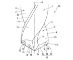
- the tip blade 7 has a first tip blade 21 extending toward the base end side in the axis O direction as it goes outward in the radial direction, and a second tip disposed on the radially outer side of the first tip blade 21. It has a blade 22 and a third tip blade 23 arranged outside the second tip blade 22 in the radial direction.
- the drill corresponding to twice the acute angle among the acute angle and obtuse angle formed between the first tip 21 and the axis O in a side view of the drill body 1 shown in FIG. 6 viewed from the radial direction.
- the tip angle ⁇ of 10 is in the range of 100 to 170 °. Since the drill 10 of this embodiment is a twist drill, the tip angle ⁇ is formed between the extended lines of the first tip blades 21 of the pair of tip blades 7 in a side view of the drill. Equal to the angle.
- the diameter (outermost diameter) of the rotation locus obtained by rotating the tip blade 7 in the circumferential direction around the axis O is ⁇ D
- the radially outer end of the first tip blade 21 is the tip blade 7.
- the distance (the length in the radial direction) indicated by the symbol a is set to the above ⁇ D ⁇ 25% or less.
- the second tip blade 22 of the tip blades 7 extends toward the tip side in the direction of the axis O or perpendicularly to the axis O as it goes outward in the radial direction.
- the second tip blade 22 is inclined toward the tip side in the axis O direction as it goes outward in the radial direction.
- the acute angle ⁇ is set to 25 ° or less. . Specifically, this angle ⁇ is 0 to 25 °.
- the radially inner end of the second distal blade 22 is disposed on the proximal end side in the axis O direction with respect to the radially outer end of the first distal blade 21.
- the inner end in the radial direction of the second tip blade 22 is disposed on the inner side in the radial direction or at the same position in the radial direction with respect to the outer end in the radial direction of the first tip blade 21.
- the inner end in the radial direction of the second tip blade 22 is disposed radially inward with respect to the outer end in the radial direction of the first tip blade 21.
- a ridge line 16 is formed at the intersecting ridge line portion between the wall surface 2 a facing the drill rotation direction T of the chip discharge groove 2 and the wall surface facing the radial outer side in the recess 8.
- the ridge line 16 is an apparent cutting edge that does not contribute to cutting, extends along the direction of the axis O, and has a radial outer end of the first tip edge 21 and a diameter of the second tip edge 22. It connects the inner edge of the direction.
- a clearance angle is also given to the ridge line 16 that does not contribute to cutting, and in the present embodiment, the clearance angle is 10 ° or less.
- a portion (wall surface facing the radially outer side in the concave portion 8) of the ridge line 16 on the tip surface 6 opposite to the drill rotation direction T gradually increases inward in the radial direction toward the opposite side of the drill rotation direction T. It is considered as a flank that inclines toward.
- the acute angle ⁇ ⁇ b> 1 is set to 10 ° or less. Specifically, this angle ⁇ 1 is 0 to 10 °.
- the radially outer end of the second tip blade 22 is disposed on a virtual extension line VL that extends the first tip blade 21 outward in the radial direction.
- the diameter (outermost diameter) of the rotation locus obtained by rotating the tip blade 7 in the circumferential direction around the axis O is ⁇ D
- the radially outer end of the second tip blade 22 is the tip blade 7. Is arranged in a range of ⁇ D ⁇ 10% or less from the outer end in the radial direction.
- the distance indicated by the symbol b (the length in the radial direction) is set to the above ⁇ D ⁇ 10% or less.
- the third tip blade 23 extends from the radially outer end of the second tip blade 22 toward the proximal end side in the axis O direction toward the radially outer side. Yes.
- the third tip blade 23 is located at the outermost diameter portion of the tip blade 7, and the radially outer end of the third tip blade 23 is connected to the tip of the outer peripheral blade 4.
- the third tip blade 23 extends along a virtual extension line VL of the first tip blade 21. That is, the third tip blade 23 is formed so as to coincide with the virtual extension line VL.
- the tip edge 7 of the present embodiment has a main cutting edge 7a and a thinning edge 7b as the cutting edge elements constituting the first to third tip edges 21 to 23 described above. These blades 7a and 7b will be described separately after the description of the thinning portion 9.
- the bottom of the drill body 1 is positioned from the wall surface 2 b facing the opposite side of the drill rotation direction T at the tip of the chip discharge groove 2 to the groove bottom (most radially inside of the chip discharge groove 2.
- a thinning portion 9 is formed in a portion located between the region extending to the wall surface portion and the front end surface 6 (the rear portion).
- the thinning portion 9 faces the drill rotation direction T, and among the first tip blades 21 of the tip blade 7, a thinning wall surface (thinning rake surface) 9a connected to a thinning blade 7b described later, and a drill rotation direction of the thinning wall surface 9a
- a thinning surface 9b is provided which is positioned at T and has a flat surface inclined so as to face the tip side in the direction of the axis O and the direction opposite to the drill rotation direction T, and is continuous with the tip surface 6.
- the angle ⁇ formed between the thinning wall surface 9a and the thinning surface 9b in the thinning portion 9 is in the range of 100 to 110 °, for example.
- the thinning surface 9 b extends so as to reach the heel portion 13 of the drill body 1.
- the leading edge 7 has a main cutting edge 7a and a thinning edge 7b as cutting edge elements constituting the first to third leading edges 21 to 23 described above. ing.
- the thinning blade 7 b is formed at the intersecting ridge line portion between the thinning wall surface 9 a of the thinning portion 9 and the tip surface 6.
- the inner end of the thinning blade 7b in the radial direction is located on the axis O.
- parts of the tip blade 7 other than the thinning blade 7b serve as the main cutting edge 7a.
- the leading edge 7 the second leading edge 22 and the third leading edge 23 are included in the main cutting edge 7 a.
- tip blades 7 contains the site
- FIG. 5 is an enlarged vertical cross-sectional view showing the main part of the tip blade 7 of the drill 10.
- reference numeral F ⁇ b> 1 denotes a work piece at a predetermined point of the first tip blade 21 of the tip blade 7.
- the cutting force acting on the material is represented, and the symbol F ⁇ b> 2 represents the cutting force acting on the work material at a predetermined point of the second tip blade 22 in the tip blade 7.
- such cutting forces F1 and F2 are generated over the entire length of the first and second tip blades 21 and 22.
- the component force in the drill feed fr direction is the thrust load F1t
- the component force in the drill radial direction is the radial load F1r
- the component force in the drill feed fr direction is the thrust load F2t
- the component force in the drill radial direction is the radial load F2r.
- the thrust loads F1t and F2t have the same direction, but the radial loads F1r and F2r have different directions.
- the radial load F2r is substantially zero.
- the tip blade 7 located on the tip surface 6 of the drill 10 is the first tip blade 21 and the second tip disposed on the radially outer side of the first tip blade 21.
- Tip blade 22 is inclined toward the proximal end side in the axis O direction as it goes outward in the radial direction, whereas the second tip blade 22 is directed outward in the radial direction. Accordingly, it is inclined toward the front end side in the direction of the axis O, or extends perpendicularly to the axis O.
- the radially inner end of the second distal blade 22 is disposed closer to the proximal end in the axis O direction than the radially outer end of the first distal blade 21, and the radially outer end of the second distal blade 22. Is located on a virtual extension line VL that extends the first tip blade 21 outward in the radial direction, and therefore has the following effects.
- the tip blade 7 is separately provided with the first tip blade 21 located radially inward at the tip of the drill 10 and the second tip blade 22 located radially outside, it is shown in FIG.
- the thrust load force acting in the direction of the drill feed fr from the drill 10 to the work material
- F1t generated when the first tip blade 21 drills the work material is the work in the work material.
- the inner periphery refers to the planned portion that becomes the inner periphery of the processed hole after processing, hereinafter referred to as the inner peripheral planned portion
- This thrust load F1t is prevented from propagating to the outer peripheral portion of the drill 10 (in the work material, the inner peripheral planned portion of the processing hole).
- the thrust load acting on the work material during drilling tends to increase at the radially inner portion (near the central portion in the radial direction including the axis O) at the drill tip.
- the thrust load acting on the material from the vicinity of the center of the drill tip propagates to the inner peripheral planned portion of the processed hole, so that delamination is likely to occur.
- the thrust load F1t acting on the work material from the vicinity of the center of the tip of the drill 10 is processed by separating the first and second tip blades 21 and 22 from each other. Propagation to the inner peripheral planned portion of the hole is prevented, so that delamination can be suppressed from occurring on the inner periphery of the processed hole after processing.
- the tip angle ⁇ of the drill is set to be small in order to suppress the delamination as in the conventional drill.
- the length of the tip edge 7 in the direction of the axis O can be reduced, the stroke during drilling (processing length in the direction of the drill feed fr) can be reduced, and the processing efficiency (productivity) can be reduced. improves.
- the tip side in the axis O direction (drill feed fr direction)
- the tip side in the axis O direction Become thrust loads F1t and F2t
- component forces in the radial direction become radial loads F1r and F2r.
- the first tip blade 21 of the tip blade 7 is inclined toward the base end side in the axis O direction as it goes radially outward
- the second tip blade 22 Inclined toward the tip end in the direction of the axis O as it goes outward in the radial direction, or extends perpendicularly to the axis O.
- the directions of the thrust loads F1t and F2t acting on the work material from the first and second tip edges 21 and 22 are the same, while the radial load F1r acting on the work material from the first tip edge 21 is the same.
- the direction and the direction of the radial load F2r acting on the work material from the second tip blade 22 are different from each other. Specifically, the radial load F1r of the first tip edge 21 acts radially outward with respect to the work material, but the radial load F2r of the second tip edge 22 is radial with respect to the work material. It works towards the inside or becomes almost zero (does not work).
- the radial load F1r directed radially outwardly acting on the work material from the first tip blade 21 is cut from the second tip blade 22 in a direction different from the radial load F1r. It can be reduced by a radial load F2r acting on the material or cannot be increased further.
- the radial load of the entire tip blade 7 of the drill 10 according to this embodiment is reduced with respect to the radial load of the entire tip blade of the conventional drill.
- tip blade 22 can be arrange
- the second tip blade 22 extends toward the tip side in the direction of the axis O as it goes outward in the radial direction or perpendicularly to the axis O, the second tip blade 22 is inserted into the machining hole. A sharp cut is made near the planned circumference.
- the chip discharge groove 2 has a spiral shape that gradually twists toward the side opposite to the drill rotation direction T from the tip end in the axis O direction toward the base end side.
- the second tip blade 22 is gradually inclined toward the proximal end side in the direction of the axis O as it goes inward from the outer end in the radial direction, whereby the radial rake angle (radial rake angle) of the second tip blade 22 is increased.
- the outer end in the radial direction of the second tip blade 22 is located on the virtual extension line VL of the first tip blade 21, the first and second tip blades 21, 22 are in the direction of the axis O. There is no large gap between them. Therefore, the above-described effect that the stroke at the time of drilling can be kept small can be surely obtained.
- the outer end in the radial direction of the second tip blade 22 is located on the virtual extension line VL of the first tip blade 21, so that, for example, the blade length of the entire tip blade 7 is set.
- the first and second tip blades 21 and 22 can be easily formed by forming the concave portion (recess 8) in part. Therefore, manufacture of the drill 10 is easy.
- the outer end in the radial direction of the second tip blade 22 is located on the virtual extension line VL of the first tip blade 21, it is easy to ensure a large re-polishing allowance for the tip blade 7. Therefore, the tool life can be extended.
- the present embodiment it is possible to improve the quality and inner diameter accuracy of the inner periphery of the machining hole drilled in the work material, to suppress the cutting resistance at the time of drilling, to improve the machining efficiency, and to cut
- the wear and chipping of the blade (tip blade 7) can be suppressed, the re-polishing allowance can be sufficiently secured, and the tool life can be extended.
- tip blade 7 has the 3rd front-end
- tip blade 23 is set to the virtual extension line VL. Since it extends along, it has the following effects. That is, according to the above configuration, the above-described remarkable effects can be obtained by the first and second tip blades 21 and 22, and the work material is further substantially simultaneously with the first and second tip blades 21 and 22.
- the third tip blade 23 is cut, and the quality and inner diameter accuracy of the inner periphery of the machining hole can be improved stably.
- the third tip blade 23 is provided between the radial outer end of the second tip blade 22 and the tip (leading edge) of the outer peripheral blade 4 extending along the chip discharge groove 2.
- the tip blade can prevent a sharp corner portion from being formed between the tip blade 7 and the outer peripheral blade 4, and these can be connected at an obtuse corner portion (see FIG. 5). That is, since the strength of the blade edge can be sufficiently increased at the connection portion between the tip blade 7 and the outer peripheral blade 4, wear and chipping of the cutting blade are remarkably suppressed.
- the third tip blade 23 when performing drilling on a composite material in which a metal plate such as titanium or aluminum is laminated on CFRP (carbon fiber reinforced resin) or a work material made of a highly extensible metal material, By adopting the above configuration (third tip blade 23), it is possible to stably perform cutting with high accuracy, which is preferable.
- the third tip blade 23 may not be provided.
- the radially inner end of the second tip blade 22 is disposed at the radially inner side or at the same radial position with respect to the radially outer end of the first tip blade 21.
- the following effects are exhibited. That is, according to the above configuration, since the first tip blade 21 and the second tip blade 22 are drilled so as to overlap in the radial direction, between the first and second tip blades 21 and 22. No uncut parts will occur. That is, without providing the function of the cutting edge to the connection portion (ridge line 16) that connects the outer end in the radial direction of the first tip blade 21 and the inner end in the radial direction of the second tip blade 22 It is possible to prevent uncut parts from occurring between the two.
- the first and second tip blades 21 and 22 between the cutting blades (tip blades 7) adjacent to each other in the circumferential direction there is no need to shift the separation positions (positions corresponding to the radially outer end of the first tip blade 21 and the radially inner end of the second tip blade 22) in the blade length direction.
- the position of the nick must be shifted in the blade length direction between the cutting blades (tip blades) adjacent in the circumferential direction. , Leaving uncut.
- adopted the said structure of this embodiment can exhibit an especially remarkable effect, especially when drilling CFRP as a work material.
- the tip angle ⁇ of the drill 10 is 100 to 170 ° in a side view when the drill body 1 is viewed from the radial direction, the following effects are obtained. That is, since the tip angle ⁇ of the drill 10 is 100 ° or more, the tip angle ⁇ does not become too small, and a radial load (a force acting toward the outer side in the radial direction with respect to the work material) at the time of drilling. ) F1r is prevented from becoming excessive. Thereby, the effect which suppresses the diameter reduction phenomenon of the processed hole after a process becomes further remarkable.
- the tip angle ⁇ of the drill 10 is 170 ° or less, the tip angle ⁇ does not become too large, and a thrust load (a force acting on the work material in the drill feed direction) at the time of drilling. It is prevented that F1t becomes excessive. Thereby, the effect which suppresses delamination becomes still more reliable.
- the radially outer end of the second tip blade 22 is arranged in a range of ⁇ D ⁇ 10% or less from the radially outermost end of the tip blade 7 as a whole (that is, the distance b in FIG. 6 is ⁇ D). ⁇ 10% or less), the following effects are obtained. That is, the second tip blade 22 can be disposed near the planned inner peripheral portion of the machining hole of the work material, and the radial load F2r directed radially inward of the second tip blade 22 is applied to the machining hole. It can be made to act directly on the inner circumference planned portion. Therefore, it is possible to more effectively suppress the occurrence of the diameter reduction phenomenon on the inner periphery of the processed hole, and the inner diameter accuracy of the processed hole is improved.
- the second tip blade 22 extends toward the tip side in the direction of the axis O as it goes outward in the radial direction or perpendicularly to the axis O, the second tip blade 22 is inserted into the machining hole. A sharp cut will be made near the planned circumference. Accordingly, the occurrence of burrs or the like on the inner periphery of the processed hole can be more effectively suppressed, and the quality of the inner periphery of the processed hole can be improved.
- the radially outer end of the first tip blade 21 is arranged in a range of ⁇ D ⁇ 25% or less from the radially outermost end of the tip blade 7 as a whole (that is, the distance a in FIG. 6 is ⁇ D). X25% or less), so that the following effects are obtained. That is, the cutting edge length of the first tip blade 21 can be secured approximately half or more than the cutting edge length of the tip blade 7 as a whole, and the second tip disposed on the radially outer side of the first tip blade 21. In forming the blade 22, it is possible to prevent the rigidity of the tip of the drill 10 from being lowered by cutting out the large concave portion 8.
- the angle ⁇ formed between the virtual plane VS perpendicular to the axis O and the second tip blade 22 in the side view of the drill in FIG. 6 is 25 ° or less, the following effects are obtained. That is, in this case, the position in the axis O direction at the radially inner end of the second tip blade 22 is prevented from being largely separated from the first tip blade 21 toward the base end side in the axis O direction. . Thereby, in forming the 2nd front-end
- the angle ⁇ 1 formed between the axis O and the ridge line 16 is 10 ° or less as viewed from the side of the drill in FIG. That is, in this case, while forming the second tip blade 22 while preventing the uncut portion between the first and second tip blades 21 and 22 from being formed, the large concave portion 8 is formed radially inward. It is prevented that the rigidity of the tip of the drill 10 is reduced due to notching or the like.
- the chip discharge groove 2 is a twist groove type drill in which the chip discharge groove 2 is gradually twisted toward the side opposite to the drill rotation direction T from the distal end surface 6 of the drill body 1 toward the proximal end side in the axis O direction.
- the present invention is not limited to this.
- FIGS. 7 to 10 what is shown in FIGS. 7 to 10 is a modification of the drill 10 described in the first embodiment, and represents a straight groove type drill 20.
- the chip discharge groove 2 extends straight along the axis O direction without being twisted in the circumferential direction.
- the present invention can be applied to such a straight groove type drill 20 as well.
- the drill 20 is different from the drill 10 described in the first embodiment.
- the inner peripheral shape of the chip discharge groove 2 is L-shaped in a cross-sectional view.
- the second margin portion 12 is provided as a margin portion other than the margin portion 11 (first margin portion).
- the drills 10 and 20 have the same configuration as each other. Therefore, in FIGS. 7 to 10, the same reference numerals as those described in the first embodiment are attached, and detailed descriptions are given. Description is omitted.
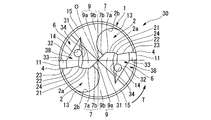
- the drill 30 of the present embodiment includes a fourth tip blade 24 that constitutes a part of the tip blade 7 and functions as a cutting blade instead of the ridge line 16 described in the drill 10 described above. Further, since the fourth tip blade 24 is formed, the shape of the recess 38 is different from the shape of the recess 8 described in the first embodiment, and the fourth flank 34 is provided in the recess 38 of the present embodiment. Is formed.
- the inner end in the radial direction of the second tip blade 22 is in the radial direction with respect to the outer end in the radial direction of the first tip blade 21.
- the tip blade 7 includes a fourth tip blade 24 as a cutting blade other than the first to third tip blades 21 to 23 described above.
- the fourth tip blade 24 connects the outer end in the radial direction of the first tip blade 21 and the inner end in the radial direction of the second tip blade 22 and gradually increases in the direction of the axis O toward the outer side in the radial direction. It extends toward the base end. Thereby, the fourth tip blade 24 is cut into the work material between the first tip blade 21 and the second tip blade 22 along the radial direction. That is, the tip blade 7 of the present embodiment has a first tip blade 21, a fourth tip blade 24, a second tip blade 22, and a third tip from the axis O (the center in the radial direction) toward the outside in the radial direction.
- the tip blade 23 is provided in this order.
- the tip surface 6 is a flank other than the first to third flank surfaces 31 to 33 described above, and is continuous to the opposite side to the drill rotation direction T of the fourth tip blade 24.
- a fourth flank 34 is provided to provide a clearance angle ⁇ 4.
- a groove-like recess 38 extending from the tip blade 7 toward the opposite side of the drill rotation direction T is formed on the tip surface 6, and the tip side in the axis O direction is formed in the recess 38.
- a bottom surface (second flank 32) facing and a wall surface facing radially outward are formed, and the wall surface is the fourth flank 34.
- the fourth flank 34 is inclined toward the inner side in the radial direction as it goes from the fourth tip edge 24 to the side opposite to the drill rotation direction T, and is inclined toward the base end side in the axis O direction. Yes.
- the clearance angle ⁇ 4 of the fourth clearance surface 34 is, for example, about 15 to 20 °.
- the acute angle ⁇ 2 among the acute angle and the obtuse angle formed between the axis O and the fourth tip edge 24 is set to 30 ° or less. Specifically, this angle ⁇ 2 is more than 0 ° and not more than 30 °.
- the drill 30 of this embodiment described above it is possible to obtain the same effects as those of the first embodiment described above. Moreover, in this embodiment, since the 4th front-end
- the drill 30 adopting the above configuration of the present embodiment is a composite material in which a metal plate such as titanium or aluminum is laminated on CFRP as a work material (in particular, a metal plate is provided at the end portion on the drill penetration side). In the case of drilling a highly stretchable metal material or the like, a particularly remarkable effect can be exhibited.
- the angle ⁇ 2 formed between the axis O and the fourth tip edge 24 is 30 ° or less in the side view of the drill in FIG. 15, the following effects are obtained. That is, since the angle ⁇ 2 is set to 30 ° or less, the fourth tip blade 24 extends substantially along the axis O without being largely inclined with respect to the axis O, and the fourth tip blade 24 The blade length can be shortened. Thereby, the blade length of the 2nd front-end
- the chip discharge groove 2 is a twist groove type drill in which the chip discharge groove 2 is gradually twisted toward the side opposite to the drill rotation direction T from the distal end surface 6 of the drill body 1 toward the proximal end side in the axis O direction.
- the present invention is not limited to this.
- FIGS. 16 to 19 what is shown in FIGS. 16 to 19 is a modification of the drill 30 described in the second embodiment, and represents a straight groove type drill 40.
- the chip discharge groove 2 extends straight along the direction of the axis O without being twisted in the circumferential direction.
- the present invention can also be applied to such a straight groove type drill 40.
- the drill 40 is different from the drill 30 described in the second embodiment.
- the inner peripheral shape of the chip discharge groove 2 is L-shaped in a cross-sectional view.
- the second margin portion 12 is provided as a margin portion other than the margin portion 11 (first margin portion).
- the drills 30 and 40 have the same configuration as each other. Therefore, in FIGS. 16 to 19, the same reference numerals as those described in the first and second embodiments are attached. Detailed description will be omitted.
- a pair (two strips) of the chip discharge grooves 2 are arranged on the outer periphery of the drill body 1 with a space in the circumferential direction, and a pair of tip blades 7 are provided.
- the formed 2 blade drill tilt drill
- the drill body 1 is formed of a hard material such as cemented carbide, but the material of the drill body 1 is not limited to this.
- the blade portion of the drill body 1 may be coated with a coating film such as a diamond film.
- the above-described drills 10 to 40 are solid-type integrally formed drills.
- the present invention provides a drill head that is detachably attached to the tip of the tool body of a blade-tip replaceable drill,
- the present invention is also applicable to a drill head that is fixedly attached to the tip by brazing or the like.
- the present invention is formed on the outer periphery of the head main body (corresponding to the drill main body 1 described in the above embodiment) rotated around the axis O together with the tool main body, A chip discharge groove 2 extending from the front end toward the base end side along the direction of the axis O, a wall surface 2a facing the drill rotation direction T of the chip discharge groove 2, and a front ridge line portion of the head main body 6 are formed. Also, it can be adopted for a drill head provided with the tip blade 7.
- the drill head is disposed on the radially outer side of the first distal edge 21 and the first distal edge 21, the distal edge 7 of which extends toward the proximal end side in the axis O direction as it goes radially outward.
- the second tip blade 22 extends toward the tip side in the direction of the axis O as it goes outward in the radial direction, or extends perpendicularly to the axis O.
- the inner end in the radial direction of the tip blade 22 is arranged on the proximal end side in the axis O direction with respect to the outer end in the radial direction of the first tip blade 21, and the outer end in the radial direction of the second tip blade 22 is It arrange
- tip angle ⁇ , angles ⁇ , ⁇ , ⁇ 1, ⁇ 2, clearance angles ⁇ 1 to ⁇ 4, and distances a and b are not limited to the numerical ranges described in the above embodiments.
- the drill 50 of the present reference example has a substantially cylindrical shape centering on the axis O, and has a drill body 1 formed of a hard material such as cemented carbide. .
- the drill body 1 is a shank portion (not shown) whose base end side portion in the axis O direction remains cylindrical, and a tip end portion in the axis O direction is a blade portion having a cutting edge.
- the cutting blade includes a tip blade 7 and an outer peripheral blade 4 which will be described later.
- the shank portion of the drill body 1 is detachably attached to the main spindle of a machine tool, a drilling machine, a three-jaw chuck of an electric drill, etc., and the drill body 1 rotates in the drill rotation direction T around the axis O.
- the drill body 1 As it is being sent, it is fed to the tip side (the lower side in FIG. 20A) along the direction of the axis O, and is cut into the work material by the blade portion for drilling.
- the work material include CFRP (carbon fiber reinforced resin) used for aircraft parts and the like, and composite materials in which a metal plate such as titanium or aluminum is laminated on the CFRP. In the present specification, these may be collectively referred to as CFRP or the like.
- the direction from the shank portion toward the blade portion in the direction along the axis O of the drill body 1 is referred to as the distal end side (the lower side in FIG. 20A), and is directed from the blade portion toward the shank portion.
- the direction is referred to as a base end side (upper side in FIG. 20A).
- a direction perpendicular to the axis O is referred to as a radial direction
- a direction approaching the axis O in the radial direction is referred to as a radial inner side
- a direction away from the axis O is referred to as a radial outer side.
- a direction that circulates around the axis O is referred to as a circumferential direction.
- a direction in which the drill 50 is rotated during cutting is referred to as a drill rotation direction T
- an opposite rotation direction is referred to as a drill rotation direction T. It is called the opposite side (anti-drill rotation direction).
- the margin part 11 forming the outermost diameter part of the blade part of the drill body 1 and the margin part 11 on the side opposite to the drill rotation direction T, and having a smaller diameter than the outer peripheral blade 4 and the margin part 11. Are formed on the second take-up surface 15.
- Chip discharge groove In this reference example, a plurality of chip discharge grooves 2 are formed on the outer periphery of the drill main body 1 at intervals in the circumferential direction, and these chip discharge grooves 2 open to the tip surface 6 of the drill main body 1, respectively. And gradually twists toward the opposite side of the drill rotation direction T from the tip end in the direction of the axis O toward the base end side, and extends in a spiral shape.
- a tip portion connected to the tip surface 6 via a tip blade 7 to be described later has a gash rake face 2c so as to be parallel to the axis O. Is formed.
- the gash rake face 2c has a parallelogram shape.
- parts other than the gash rake face 2c) located in the base end side of the axis O direction rather than the gash rake face 2c among the chip discharge grooves 2 is the base end of the axis O direction from the gash rake face 2c. As it goes to the side, it gradually twists and extends toward the side opposite to the drill rotation direction T.
- the chip discharge grooves 2 are spaced at equal intervals in the circumferential direction (equal pitch) on the outer periphery of the drill body 1 so as to be rotationally symmetric with respect to the axis O. Is arranged).
- the drill 50 of the present reference example is a twist drill in which two pieces of the chip discharge grooves 2 are arranged in the drill body 1 in a 180-degree rotational symmetry with respect to the axis O.
- the chip discharge groove 2 is open to the distal end surface 6 of the drill body 1 and extends toward the proximal end side, and is not particularly illustrated, but in the vicinity of, for example, the central portion along the axis O direction of the drill body 1, The outer peripheral surface is cut out radially outward. And in the drill main body 1, the range in which the chip
- the chip discharge groove 2 has a concave curved inner surface and is concave toward the radially inner side and the drill rotation direction T. It is formed so as to be recessed. Further, the chip discharge groove 2 is formed so that the groove depth is deepest (the inner periphery of the groove is closest to the axis O) in the vicinity of the central portion along the circumferential direction.
- the outer peripheral blade 4 has a leading edge at the tip in the axis O direction.
- the outer diameter of the blade portion of the drill main body 1 is gradually made slightly smaller from the distal end in the direction of the axis O toward the proximal end side, and a back taper is given.
- the outer diameter of 4 is gradually reduced from the distal end of the drill body 1 toward the proximal end side.
- the present invention is not limited to this, and the back taper may not be provided to the blade portion of the drill body 1.
- the margin portion 11 is connected to the wall surface 2a of the chip discharge groove 2 facing the drill rotation direction T, and is formed by rotating the outermost diameter of the tip blade 7 to be described later (the outer end in the radial direction of the tip blade 7 rotates around the axis O). It is formed so as to be located on a virtual cylindrical surface having an outer diameter substantially equal to the diameter ⁇ D of the circle of the rotation locus.
- a cross ridge line portion between the wall surface 2 a of the chip discharge groove 2 facing the drill rotation direction T and the margin portion 11 is the outer peripheral blade 4.
- the outer peripheral blade 4 and the margin portion 11 along the chip discharge groove 2 are also moved from the distal end in the axis O direction to the proximal end side. As it goes, it gradually twists toward the side opposite to the drill rotation direction T and extends in a spiral shape.
- the chip discharge groove 2, the outer peripheral edge 4, and the margin portion 11 have the same twist angle (lead, axial tilt angle).
- the twist angle of the outer peripheral blade 4 is, for example, 40 ° or less.
- a portion positioned between the margin portion 11 and the chip discharge groove 2 adjacent to the opposite side of the margin portion 11 in the drill rotation direction T is defined as a second picking surface 15. Yes.
- the second picking surface 15 is disposed so as to recede inward in the radial direction with respect to the rotation locus of the outer peripheral blade 4 around the axis O.
- the second picking surface 15 is continuous with the drill portion T on the outer peripheral surface of the drill body 1 opposite to the drill rotation direction T, and has an outer diameter smaller than the outer diameter of the margin portion 11. Yes.
- the retreating amount (second picking depth) by which the second picking surface 15 moves back inward in the radial direction from the rotation locus of the outer peripheral blade 4 is constant over the entire circumferential direction of the second picking surface 15. May be.
- the amount of retraction of the second picking surface 15 from the end of the drill rotation direction T toward the inner side in the radial direction gradually increases from the rotation locus of the outer peripheral blade 4 toward the opposite side of the drill rotation direction T. May be.
- the ridge portion 15 is an intersection ridge portion of the outer periphery of the drill main body 1 and the wall surface 2b facing the opposite side of the chip discharge groove 2 from the drill rotation direction T.
- the heel portion 13 is pointed toward the side opposite to the drill rotation direction T and has a ridge shape extending along the chip discharge groove 2.
- the tip surface (tip flank surface) 6 is opposite to the drill rotation direction T from the tip inner blade 27a located radially inside of the tip inner blade 27a and the tip outer blade 27b described later of the tip blade 7.
- the tip clearance flank 6a which inclines toward the base end side in the axis O direction as it goes toward the side, and the axis O direction as it goes away from the drill rotation direction T from the tip outer blade 27b positioned on the radially outer side.
- a distal outer clearance surface 6b that is inclined toward the proximal end side.
- the tip inner flank 6a and the tip outer flank 6b are gradually inclined toward the base end side in the direction of the axis O in the direction opposite to the drill rotation direction T, whereby the tip inner blade 27a and A clearance angle is given to each of the distal end outer blades 27b.
- the in-tip clearance surface 6a is connected to the front portion having a rectangular shape that is long in the radial direction and the opposite side to the drill rotation direction T of the front portion, and is larger than the front portion. And a fan-shaped rear portion set at a clearance angle.
- the present invention is not limited to this, and the front clearance surface 6a has the clearance angle of the front portion and the rear portion set to be the same, and the front portion and the rear portion are formed flush with each other. Also good.
- the tip outer relief surface 6b when viewed from the front of the drill, has an arc-shaped belt shape extending along the circumferential direction.
- a coolant hole 14 is opened in at least one of the front end surface 6 and the thinning surface 19.
- the coolant hole 14 opens in the rear portion of the in-tip clearance surface 6 a in the tip surface 6.
- the opening shape of the coolant hole 14 is circular, but is not limited thereto, and may be other polygonal shapes, elliptical shapes, or the like, for example. .
- the coolant hole 14 is twisted and extended in the drill body 1 along the chip discharge groove 2 (with a lead substantially equal to the chip discharge groove 2). It penetrates in the O direction.
- coolant compressed air, oily or water-soluble cutting fluid supplied from the spindle of the machine tool circulates, and this coolant is used to process the tip of the drill body 1 and the work material. It is drained to the site.
- the tip blade 7 includes a tip portion of the wall surface 2 a facing the drill rotation direction T of the chip discharge groove 2 (that is, a gash rake face 2 c) and a tip face 6 of the drill body 1. It is formed at a crossing ridge line portion between the gash rake face 2c and the portion that is connected to the side opposite to the drill rotation direction T, and the gash rake face 2c is used as a rake face and the tip face 6 is used as a flank face.
- the tip blade 7 extends from the axis O in the drill body 1 to the radially outer end (outermost circumference).
- the tip blade 7 of the present reference example has a tip inner blade 27a that gradually extends toward the base end side in the axis O direction from the axis O toward the radially outer side, and a radially outer end of the tip inner blade 27a. As it goes from the outer end toward the outer side in the radial direction, it gradually extends toward the base end side in the axis O direction, and the displacement amount (that is, the inclination) in the axis O direction per unit length along the radial direction is A distal outer blade 27b that is larger than the distal inner blade 27a.
- the tip blade 7 has a tip inner blade 27a and a tip outer blade 27b that are radially connected to each other, and the tip inner blade 27a is disposed on the radially inner side of the tip outer blade 27b, and the tip outer blade 27b is arrange
- the inclination angle of the tip inner blade 27a with respect to the axis O (the acute angle formed between the axis O and the tip inner blade 27a).
- tip blade 7 is extended along the radial direction by the drill front view which looked at the drill main body 1 toward the base end side from the front-end
- the tip blade 7 extends along the radial direction means an imaginary straight line passing through the outer end (outer peripheral corner) 7c in the radial direction of the tip blade 7 and the axis O in the drill front view.
- the angle formed between the tip blade 7 and the blade length direction is a small value (approximately 0 °) close to zero. Specifically, the angle is, for example, 5 ° or less. (0 to 5 °). In the example illustrated in this reference example, the angle is 0 °. That is, the tip blade 7 of the present reference example is set to have a core height of zero, which is neither raised nor lowered.
- the core height is a distance at which the tip blade is separated from a virtual straight line passing through the axis parallel to the blade length direction of the tip blade in a front view of the drill.
- the distance L by which the tip blade 107 is separated from the virtual straight line passing through the axis O and parallel to the blade length direction of the tip blade 107. Is the core height.
- the drill 50 of the present reference example has a center height of the tip edge 7 of zero.
- the tip blade 7 is linear, and the center height is zero over the entire length of the tip blade 7 (over the entire tip inner blade 27a and tip outer blade 27b). Is set to
- the gash rake face 2c of the chip discharge groove 2 serving as the rake face of the tip blade 7 is formed so as to be parallel to the axis O of the drill body 1, so that the axial of the tip blade 7 is axial.
- the rake angle (axial rake angle) is a negative angle (0 °) over the entire blade length of the tip blade 7 (over the entire tip inner blade 27a and tip outer blade 27b).
- the axial rake angle of the tip blade 7 is a negative angle (0 °)
- the tip blade 7 extends along the radial direction (zero core height).
- the radial rake angle R of the outer peripheral corner 7c of the tip blade 7 is a negative angle (0 °).
- Thininning surface 20A and 20B the bottom of the drill body 1 from the wall surface 2b facing away from the drill rotation direction T at the tip of the chip discharge groove 2 (the innermost radial direction of the chip discharge groove 2).
- a thinning surface 19 is formed in a portion located between the region extending to the wall surface portion located at the front end surface 6 and the tip surface 6.
- the thinning surface 19 is inclined toward the proximal end side in the axis O direction as it goes from the distal end surface 6 to the side opposite to the drill rotation direction T.
- the displacement amount (that is, the inclination) in the direction of the axis O per unit length along the drill rotation direction T on the thinning surface 19 is larger than the displacement amount on the tip surface 6.
- the gash rake face 2c of the chip discharge groove 2 that becomes the rake face of the tip blade 7 is formed so as to be parallel to the axis O of the drill body 1.
- the axial rake angle of the tip blade 7 is a negative angle (0 °).
- the tip blade 7 extends along the radial direction of the drill body 1 and is set to have a center height of zero that is neither raised nor lowered. Yes.
- an angle formed between the radial outer end (outer peripheral corner) 7c of the tip blade 7 and the imaginary straight line passing through the axis O and the blade length direction of the tip blade 7 is , Approximately 0 °.
- the drills 100 and 110 are a drill body 101 that is rotated around an axis O, a chip discharge groove 102 that is formed on the outer periphery of the drill body 101 and extends from the distal end toward the proximal end along the axis O direction, A tip blade 107 formed at a crossing ridge line portion between the wall surface of the chip discharge groove 102 facing the drill rotation direction T and the tip surface of the drill main body 101.
- the radial edge of the tip blade 107 (outer periphery corner) 107 c is closely related to the finishing accuracy of the inner periphery of the drilled hole.
- the chip discharge groove 102 opens to the distal end surface of the drill body 101 and gradually increases from the distal end surface toward the proximal end side in the axis O direction. It twists toward the opposite side of the drill rotation direction T and extends in a spiral shape. For this reason, the axial rake angle (axial rake angle) of the tip blade 107 is a positive angle. In addition, as shown in FIG. 30, the radial rake angle (radial rake angle) R of the outer peripheral corner 107c of the tip blade 107 is a positive angle (+).
- the inner circumference of the machining hole of the workpiece W shown in FIG. Etc. are likely to occur. That is, the work material W made of CFRP or the like has fiber orientation, and in FIG. 33, the fiber orientation is the vertical direction (longitudinal direction). For this reason, when the radial rake angle R of the outer peripheral corner 107c of the tip blade 107 is a positive angle (+), the cutting edge is cut into an acute angle in the region A of the inner periphery of the processing hole (the cutting edge is a fiber streak). In contrast, the fiber is easily peeled off and the burrs are generated.
- the axial rake angle of the tip blade 107 is a negative angle (0 °).
- the radial rake angle R of the outer peripheral corner 107c of the tip blade 107 is a negative angle ( ⁇ ) that is larger on the negative angle side than 0 °.
- the axial rake angle of the tip blade 7 is a negative angle (0 °), and the tip blade 7 extends along the radial direction (zero core height). Therefore, in the front view of the drill shown in FIG. 21, the radial rake angle R of the outer peripheral corner 7c of the tip blade 7 is a negative angle (0 °). For this reason, when a drilling material such as CFRP is drilled by the drill 50 of this reference example, the region indicated by the symbol A (in the circumferential direction) in the inner periphery of the processing hole of the workpiece W shown in FIG. The occurrence of burrs and the like is remarkably suppressed in the region (region) and in the region indicated by the symbol B (region in the circumferential direction).
- the cutting edge is cut at an acute angle with the conventional drill 100 (see FIGS. 29A, 29B, and 30) (the cutting edge is a fiber streak).
- the cutting edge is cut at a right angle, so that the fiber is prevented from being peeled off.
- the conventional drill 110 see FIGS. 31A, 31B, and 32
- cuts the blade edge at an obtuse angle the blade edge cuts smoothly with respect to the fiber streak but bluntly, leaving uncut fibers.
- the drill 50 of this reference example since the cutting edge cuts at a right angle, the occurrence of uncut fiber is suppressed. Therefore, the drill 50 of this reference example can suppress the occurrence of burrs or the like over the entire circumferential direction of the inner periphery of the processed hole.
- the part located in the base end side of the axis O direction from the gash rake face 2c in the chip discharge groove 2 gradually moves in the drill rotation direction toward the base end side in the axis O direction from the gash rake face 2c. Since the chip discharge groove 2 is a spiral groove extending in a spiral shape on the outer periphery of the drill body 1, the chip discharge performance is maintained well.
- the tip blade 7 has a tip inner blade 27a and a tip outer blade 27b.
- the following effects are obtained. That is, in this case, a corner (outer periphery corner 7c) where the tip blade 7 (the outer tip blade 27b) and the outer peripheral blade 4 (the leading edge thereof) are connected is formed at a large obtuse angle, and the cutting edge at this corner portion is formed. Defects are remarkably suppressed, tool life is extended, and stable drilling can be performed.
- the angle is twice the acute angle.
- the corresponding tip angle of the drill 50 (tip angle between the pair of tip outer blades 27b) becomes small. For this reason, when the work material is drilled, the thrust load acting on the work material from the tip outer blade 27b can be reduced, and delamination or the like on the inner periphery of the work hole is suppressed.
- FIGS. 22A to 25 Detailed description of the same components as those in the above-described reference example will be omitted, and only differences will be mainly described below.
- the drill 60 of the present embodiment differs from the drill 50 described in the above reference example mainly in the shape of the tip (tip surface 26, tip blade 17) of the drill body 1.
- the tip surface (tip flank surface) 26 of the drill body 1 is the most of first to fourth tip blades 21 to 24 described later of the tip blade 17.
- a first flank 31 that inclines toward the base end side in the direction of the axis O as it goes from the first tip edge 21 located radially inside to the opposite side of the drill rotation direction T, and the first to fourth tip edges 21 to 24, a third flank 33 that inclines toward the base end side in the direction of the axis O from the third tip edge 23 located on the outermost side in the radial direction toward the side opposite to the drill rotation direction T;
- the drill tip rotation direction T is opposite to the second tip blade 22 located on the radially outer side.
- first to fourth flank surfaces 31 to 34 are gradually inclined toward the base end side in the direction of the axis O as they go to the opposite side of the drill rotation direction T, so that the first to fourth tip ends
- Each of the blades 21 to 24 has a clearance angle.
- the first flank 31, the third flank 33, and the fourth flank 34 are inclined toward the base end side in the axis O direction toward the radially outer side.
- the 2nd flank 32 inclines toward the front end side of the axis line O direction as it goes to radial direction outer side.
- the front end surface 26 is connected to the side opposite to the drill rotation direction T of the front end blade 17, and as a whole, a front portion having a generally rectangular shape that is long in the radial direction, and a drill in the front portion A fan-shaped rear portion that is connected to the side opposite to the rotation direction T and has a larger clearance angle than the front portion.
- the present invention is not limited to this, and the first flank 31 and the third flank 33 among the first to fourth flank 31 to 34 of the front end surface 26 are the front part and the rear part.
- the clearance angles may be set equal to each other, and the front portion and the rear portion may be formed flush with each other.
- the distal end surface 26 has a concave portion 18 that extends from the distal end blade 17 toward the side opposite to the drill rotation direction T and that is recessed toward the proximal end side in the axis O direction.
- the recess 18 has a groove shape extending from the tip blade 17 toward the side opposite to the drill rotation direction T, and is formed from the front portion to the rear portion of the tip surface 26.
- the recess 18 has a bottom surface that is located on the radially outer side of the recess 18 and faces the front end side in the axis O direction, and a wall surface that is located on the radially inner side and faces the radially outer side of the recess 18. is doing.
- the bottom surface of the recess 18 is a second flank 32 and the wall surface is a fourth flank 34.
- the position at which the coolant hole 14 is opened at the distal end portion of the drill body 1 is set to the inner side in the radial direction than the concave portion 18.
- the tip blade 17 has a gash of the tip portion (gash rake face 2 c) of the wall surface 2 a facing the drill rotation direction T of the chip discharge groove 2 and the tip face 26 of the drill body 1. It is formed at a crossing ridge line portion between the rake face 2c and the portion that is connected to the opposite side of the drill rotation direction T.
- the gash rake face 2c is a rake face and the tip face 26 is a flank face.
- the leading edge 17 extends from the axis O in the drill body 1 to the radially outer end (outermost circumference).
- the tip blade 17 of the present embodiment has a first tip blade 21 extending toward the base end side in the axis O direction as it goes outward in the radial direction, and a second tip disposed on the radially outer side of the first tip blade 21.
- a fourth tip blade 24 for connecting the two.
- tip blades 17 is extended toward the base end side of an axis line O direction gradually as it goes to the outer side of radial direction from on the axis line O.
- the second tip blade 22 extends toward the tip side in the direction of the axis O as it goes outward in the radial direction, or extends perpendicularly to the axis O.
- tip blade 22 inclines toward the front end side of the axis line O direction as it goes to the outer side of radial direction.
- the radially inner end of the second distal blade 22 is disposed on the proximal end side in the axis O direction with respect to the radially outer end of the first distal blade 21.
- the inner end in the radial direction of the second tip blade 22 is disposed on the outer side in the radial direction with respect to the outer end in the radial direction of the first tip blade 21.
- the 4th front-end blade 24 which connects the radial direction inner end of the 2nd front-end
- the radially outer end of the second tip blade 22 is disposed on a virtual extension line VL that extends the first tip blade 21 outward in the radial direction.
- the diameter (outermost diameter) of the rotation locus obtained by rotating the tip blade 17 in the circumferential direction around the axis O is ⁇ D
- the radially outer end of the second tip blade 22 is the radial direction of the tip blade 17. Is arranged in a range of ⁇ D ⁇ 10% or less from the outer end (outer periphery corner 17c).
- the distance (the length in the radial direction) indicated by the symbol b is set to the above ⁇ D ⁇ 10% or less.
- the third tip blade 23 extends from the radially outer end of the second tip blade 22 toward the proximal end side in the axis O direction as it goes radially outward.
- the third tip blade 23 is located at the outermost diameter portion of the tip blade 17, and the radially outer end (outer peripheral corner 17 c) of the third tip blade 23 is at the tip (leading edge) of the outer peripheral blade 4.
- the third tip blade 23 extends along the virtual extension line VL of the first tip blade 21. That is, the third tip blade 23 is formed so as to coincide with the virtual extension line VL.
- the tip blade 17 of the present embodiment has the first tip blade 21, the fourth tip blade 24, the second tip blade 22, and the outer side in the radial direction from the axis O (diameter center), and The third tip blade 23 is provided in this order.
- FIGS. 23A to 25 show a modification of the drill 60 of the present embodiment.
- the tip blade 17 does not have the third tip blade 23, and the outer end in the radial direction of the second tip blade 22 is the outer peripheral corner 17 c and is connected to the leading edge of the outer peripheral blade 4. Yes.
- the tip angle ⁇ of the drill 60 corresponding to twice the acute angle among the acute and obtuse angles formed between the first tip blade 21 and the axis O is 100. It is in the range of ⁇ 170 °. Since the drill 60 of the present embodiment is a twist drill, the tip angle ⁇ is formed between the extended lines of the first tip blades 21 of the pair of tip blades 17 in a side view of the drill. Equal to the angle.
- the diameter (outermost diameter) of the rotation locus obtained by rotating the tip blade 17 in the circumferential direction around the axis O is ⁇ D
- the radially outer end of the first tip blade 21 is the radial direction of the tip blade 17. Is arranged in a range of ⁇ D ⁇ 25% or less from the outer end. Specifically, in the side view of the drill in FIG. 25, the distance indicated by the symbol a (the length in the radial direction) is set to the above ⁇ D ⁇ 25% or less.
- the acute angle ⁇ among the acute angle and the obtuse angle formed between the virtual plane VS perpendicular to the axis O and the second tip edge 22 is set to 25 ° or less. ing. Specifically, this angle ⁇ is 0 to 25 °.
- the acute angle ⁇ 2 among the acute angle and the obtuse angle formed between the axis O and the fourth tip edge 24 is set to 30 ° or less. Specifically, this angle ⁇ 2 is more than 0 ° and not more than 30 °.
- the angle ⁇ formed between the gash rake face 2c located at the tip of the chip discharge groove 2 and the thinning face 19 is, for example, about 120 °.
- FIG. 24 is an enlarged view showing the vicinity of the tip blade 17 of the drill 60.
- Reference numeral F1 in the drawing acts on the work material at a predetermined point of the first tip blade 21 in the tip blade 17.
- the cutting force is represented, and the symbol F ⁇ b> 2 represents the cutting force acting on the work material at a predetermined point of the second tip blade 22 in the tip blade 17.
- such cutting forces F1 and F2 are generated over the entire length of the first and second tip blades 21 and 22.
- the cutting force is similarly produced in the 4th front-end
- the component force in the drill feed fr direction is the thrust load F1t
- the component force in the drill radial direction is the radial load F1r
- the component force in the drill feed fr direction is the thrust load F2t
- the component force in the drill radial direction is the radial load F2r.
- the thrust loads F1t and F2t have the same direction, but the radial loads F1r and F2r have different directions.
- the radial load F2r is substantially zero (when the second tip blade 22 extends perpendicular to the axis O).
- the axial rake angle of the tip blade 17 is set to a negative angle (0 °) and the tip blade 17 extends along the radial direction as in the above-described reference example ( Therefore, the radial rake angle R of the outer peripheral corner 17c of the tip edge 17 becomes a negative angle (0 °). Therefore, also in the drill 60 of this embodiment, the effect similar to the above-mentioned reference example is acquired, and the finishing precision of the inner periphery of the processing hole drilled in the workpiece W can be improved stably.
- the tip blade 17 positioned on the tip surface 26 of the drill 60 includes the first tip blade 21 and the second tip blade 22 disposed on the radially outer side of the first tip blade 21. ing. Specifically, the first tip blade 21 is inclined toward the proximal end side in the axis O direction as it goes outward in the radial direction, whereas the second tip blade 22 is directed outward in the radial direction. Accordingly, it is inclined toward the front end side in the direction of the axis O, or extends perpendicularly to the axis O.
- the radially inner end of the second distal blade 22 is disposed closer to the proximal end in the axis O direction than the radially outer end of the first distal blade 21, and the radially outer end of the second distal blade 22. Is located on a virtual extension line VL that extends the first tip blade 21 outward in the radial direction, and therefore has the following effects.
- the tip blade 17 is separately provided with the first tip blade 21 positioned radially inward at the tip of the drill 60 and the second tip blade 22 positioned radially outward, it is shown in FIG.
- the thrust load force acting from the drill 60 toward the drill feed fr direction on the work material
- F1t generated when the first tip 21 drills the work material is the work in the work material.
- the inner periphery refers to the planned portion that becomes the inner periphery of the processed hole after processing, hereinafter referred to as the inner peripheral planned portion
- This thrust load F1t is prevented from propagating to the outer peripheral portion of the drill 60 (in the work material, the inner peripheral planned portion of the processing hole).
- the thrust load acting on the work material during drilling tends to increase at the radially inner portion (near the central portion in the radial direction including the axis O) at the drill tip.
- the thrust load acting on the material from the vicinity of the center of the drill tip propagates to the inner peripheral planned portion of the processed hole, so that delamination is likely to occur.
- the thrust load F1t acting on the work material from the vicinity of the center of the tip of the drill 60 is processed by separating the first and second tip blades 21 and 22 from each other. Propagation to the inner peripheral planned portion of the hole is prevented, so that delamination can be suppressed from occurring on the inner periphery of the processed hole after processing.
- the tip angle ⁇ of the drill is reduced (for example, 100) in order to suppress the delamination as in the conventional drill. It is not necessary to set it to be smaller (°) or to form an acute angle so as to sharpen the tip of the drill. Therefore, according to this embodiment, the blade length of the tip blade 17 can be kept short. Thereby, the cutting resistance at the time of drilling can be suppressed. In addition, the length of the tip edge 17 in the axis O direction can be kept small, the stroke during drilling (machining length in the drill feed fr direction) can be kept small, and the machining efficiency (productivity) can be improved. improves.
- the tip side in the axis O direction (drill feed fr direction)
- the tip side in the axis O direction Become thrust loads F1t and F2t
- component forces in the radial direction become radial loads F1r and F2r.
- the first tip blade 21 of the tip blade 17 is inclined toward the base end side in the axis O direction as it goes outward in the radial direction
- the second tip blade 22 is Inclined toward the tip end in the direction of the axis O as it goes outward in the radial direction, or extends perpendicularly to the axis O.
- the directions of the thrust loads F1t and F2t acting on the work material from the first and second tip edges 21 and 22 are the same, while the radial load F1r acting on the work material from the first tip edge 21 is the same.
- the direction and the direction of the radial load F2r acting on the work material from the second tip blade 22 are different from each other. Specifically, the radial load F1r of the first tip edge 21 acts radially outward with respect to the work material, but the radial load F2r of the second tip edge 22 is radial with respect to the work material. It works towards the inside or becomes almost zero (does not work).
- the radial load F1r directed radially outwardly acting on the work material from the first tip blade 21 is cut from the second tip blade 22 in a direction different from the radial load F1r.
- tip blade 22 can be arrange
- the second tip blade 22 extends toward the tip side in the direction of the axis O as it goes outward in the radial direction or perpendicularly to the axis O, the second tip blade 22 is inserted into the machining hole. A sharp cut is made near the planned circumference. Therefore, it is possible to effectively suppress the occurrence of burrs and the like on the inner periphery of the processed hole, and to improve the quality of the inner periphery of the processed hole.
- the outer end in the radial direction of the second tip blade 22 is located on the virtual extension line VL of the first tip blade 21, the first and second tip blades 21, 22 are in the direction of the axis O. There is no large gap between them. Therefore, the above-described effect that the stroke at the time of drilling can be kept small can be surely obtained.
- the radially outer end of the second tip blade 22 is located on the virtual extension line VL of the first tip blade 21, for example, the blade length of the entire tip blade 17 is set.
- the first and second tip blades 21 and 22 can be easily formed by forming the concave portion (the concave portion 18) in a part. Therefore, manufacture of the drill 60 is easy.
- the outer end in the radial direction of the second tip blade 22 is located on the virtual extension line VL of the first tip blade 21, it is easy to secure a large re-polishing allowance for the tip blade 17. Therefore, the tool life can be extended.
- the present embodiment it is possible to improve the quality and inner diameter accuracy of the inner periphery of the machining hole drilled in the work material, to suppress the cutting resistance at the time of drilling, to improve the machining efficiency, and to cut Abrasion and chipping of the blade (tip blade 17) can be suppressed, a sufficient re-polishing allowance can be secured, and the tool life can be extended.
- the tip blade 17 has the third tip blade 23 disposed on the radially outer side of the second tip blade 22, and this third tip Since the blade 23 extends along the virtual extension line VL, the following effects are obtained. That is, according to the above configuration, the above-described remarkable effects can be obtained by the first and second tip blades 21 and 22, and the work material is further substantially simultaneously with the first and second tip blades 21 and 22.
- the third tip blade 23 is cut, and the quality and inner diameter accuracy of the inner periphery of the machining hole can be improved stably.
- the third tip blade 23 is provided between the radial outer end of the second tip blade 22 and the tip (leading edge) of the outer peripheral blade 4 extending along the chip discharge groove 2.
- the tip blade can prevent a sharp corner portion from being formed between the tip blade 17 and the outer peripheral blade 4, and these can be connected by an obtuse corner portion. That is, since the edge strength can be sufficiently increased at the connection portion (outer peripheral corner 17 c) between the tip blade 17 and the outer peripheral blade 4, wear and chipping of the cutting edge are remarkably suppressed.
- the drill 60 when performing drilling on a composite material in which a metal plate such as titanium or aluminum is laminated on CFRP (carbon fiber reinforced resin) or a work material made of a highly extensible metal material, By adopting the above configuration (third tip blade 23), it is possible to stably perform cutting with high accuracy, which is preferable.
- the drill 60 according to the present embodiment does not need to be provided with the third tip blade 23.
- tip blade 24 which connects these is arrange
- tip blade 22 between the 1st and 2nd front-end
- the first and second tip blades 21 and 22 are compared with the expected positions. Can be arranged freely. Therefore, it is possible to easily meet various requests for the drill 60.
- the tip angle ⁇ of the drill 60 is 100 to 170 ° in a side view when the drill body 1 is viewed from the radial direction, and thus the following operational effects are obtained. That is, since the tip angle ⁇ of the drill 60 is 100 ° or more, the tip angle ⁇ does not become too small, and a radial load (a force acting toward the outer side in the radial direction with respect to the work material) at the time of drilling. ) F1r is prevented from becoming excessive. Thereby, the effect which suppresses the diameter reduction phenomenon of the processed hole after a process becomes further remarkable.
- the tip angle ⁇ of the drill 60 is 170 ° or less, the tip angle ⁇ does not become too large, and a thrust load during drilling (force acting on the work material in the drill feed direction) It is prevented that F1t becomes excessive. Thereby, the effect which suppresses delamination becomes still more reliable.
- the radially outer end of the second tip blade 22 is arranged in a range of ⁇ D (diameter of the rotation locus of the tip blade 17) ⁇ 10% or less from the radially outermost end of the tip blade 17 as a whole. (That is, since the distance b in FIG. 22A is ⁇ D ⁇ 10% or less), the following effects are obtained. That is, the second tip blade 22 can be disposed near the planned inner peripheral portion of the machining hole of the work material, and the radial load F2r directed radially inward of the second tip blade 22 is applied to the machining hole. It can be made to act directly on the inner circumference planned portion. Therefore, it is possible to more effectively suppress the occurrence of the diameter reduction phenomenon on the inner periphery of the processed hole, and the inner diameter accuracy of the processed hole is improved.
- the second tip blade 22 extends toward the tip side in the direction of the axis O as it goes outward in the radial direction or perpendicularly to the axis O, the second tip blade 22 is inserted into the machining hole. A sharp cut will be made near the planned circumference. Accordingly, the occurrence of burrs or the like on the inner periphery of the processed hole can be more effectively suppressed, and the quality of the inner periphery of the processed hole can be improved.
- the outer end in the radial direction of the first tip blade 21 is arranged in a range of ⁇ D (diameter of the rotation trajectory of the tip blade 17) ⁇ 25% or less from the radially outermost end of the tip blade 17 as a whole.
- ⁇ D diameter of the rotation trajectory of the tip blade 17
- the following effects are obtained. That is, the cutting edge length of the first tip blade 21 can be ensured to be approximately half or more of the blade length of the tip blade 17 as a whole, and the second tip disposed on the radially outer side of the first tip blade 21.
- the blade 22 is formed, it is possible to prevent the rigidity of the tip of the drill 60 from being lowered by cutting out the large recess 18 or the like.
- tip of the drill 60 falls by notching the big recessed part 18 etc., for example.
- the effect of reducing the stroke during drilling is further ensured.
- the angle ⁇ 2 formed between the axis O and the fourth tip blade 24 is 30 ° or less in the side view of the drill shown in FIG. 25, the following effects are obtained. That is, in this case, since the angle ⁇ 2 is set to 30 ° or less, the fourth tip blade 24 extends substantially along the axis O without being largely inclined with respect to the axis O. The blade length of 24 can be shortened. Thereby, the blade length of the 2nd front-end
- the radial inner end of the second tip blade 22 has a diameter relative to the radial outer end of the first tip blade 21.
- the fourth tip edge 24 does not act as a cutting edge, but is formed in a mere ridgeline (a pseudo cutting edge). According to the above configuration, since the drilling is performed so that the first tip blade 21 and the second tip blade 22 overlap in the radial direction, between the first and second tip blades 21 and 22, There are no uncut parts.
- the separation positions positions corresponding to the radial outer end of the first tip blade 21 and the radial inner end of the second tip blade 22) need not be shifted from each other in the blade length direction (radial direction).
- the nick positions are shifted in the blade length direction between the cutting blades (tip blades) adjacent in the circumferential direction. Otherwise, uncut parts will occur.
- the acute angle of the acute angle and the obtuse angle formed between the axis O and the ridge line is 10 ° or less in a side view of the drill. That is, in this case, while forming the second tip blade 22 while preventing the uncut portion between the first and second tip blades 21 and 22 from being formed, the large concave portion 18 is formed radially inward. It is possible to prevent the rigidity of the tip of the drill 60 from being lowered due to notching or the like.
- FIGS. 26A and 26B Detailed description of the same components as those in the above-described reference example and the third embodiment will be omitted, and only different points will be described below.
- the drill 70 of the present embodiment is different from the drills 50 and 60 described in the above-described reference example and the third embodiment mainly in the shape of the chip discharge groove 2 of the drill body 1 and the second margin portion 12. Is different.
- the chip discharge groove 2 extends in parallel to the axis O. That is, the chip discharge groove 2 extends straight along the axis O direction without being twisted in the circumferential direction. That is, the drill 70 is a straight groove type drill. And the gash rake face 2c is formed in the front-end
- the drill 70 of the present embodiment has the second margin portion 12 as a margin portion other than the margin portion 11 (first margin portion).
- the second margin portion 12 is formed to have substantially the same diameter as the first margin portion 11, and a second picking surface 15 and a chip discharge groove adjacent to the second picking surface 15 on the opposite side to the drill rotation direction T. Between the two.
- the axial rake angle of the tip blade 17 is set to a negative angle (0 °) and the tip blade 17 is along the radial direction as in the above-described reference example and the third embodiment. Therefore, the radial rake angle R of the outer peripheral corner 17c of the tip blade 17 becomes a negative angle (0 °). Therefore, also in the drill 70 of this embodiment, the same effect as the above-mentioned reference example and 3rd Embodiment is acquired, and the finishing precision of the inner periphery of the drilled hole drilled in the workpiece W is improved stably. be able to.
- the chip discharge groove 2 is a straight groove extending linearly on the outer periphery of the drill body 1. Therefore, it is easy to form the chip discharge groove at the time of drill manufacture.
- a pair (two strips) of chip discharge grooves 2 are arranged on the outer periphery of the drill main body 1 at intervals in the circumferential direction.
- 7 and 17 are two-edged drills (twist drills) in which a pair (two) are formed, but the present invention is not limited to this. That is, according to the present invention, a drill 60 having three or more blades in which three or more chip discharge grooves 2 are arranged at intervals in the circumferential direction on the outer periphery of the drill body 1 and three or more tip blades 17 are formed. , 70 is also applicable.
- the drill body 1 is formed of a hard material such as cemented carbide, but the material of the drill body 1 is not limited to this. Further, the blade portion of the drill body 1 may be coated with a coating film such as a diamond film.
- the above-described drills 50 to 70 are solid-type integrally formed drills.
- the present invention relates to a drill head that is detachably attached to the tip of the tool body of the blade-tip replaceable drill,
- the present invention is also applicable to a drill head that is fixedly attached to the tip by brazing or the like.
- the present invention is formed on the outer periphery of the head main body (corresponding to the drill main body 1 described in the above embodiment) rotated around the axis O together with the tool main body, A chip discharge groove 2 extending from the front end toward the base end side along the axis O direction, a wall surface 2a facing the drill rotation direction T of the chip discharge groove 2, and a front ridge line portion of the head main body 26 are formed. Also, it can be adopted for a drill head provided with the tip blade 17. In this case, the drill head has a gash rake face 2c formed parallel to the axis O at the tip end connected to the tip face 26 via the tip blade 17 in the wall surface 2a of the chip discharge groove 2.
- the distal end blade 17 When viewed from the front of the drill when the head body is viewed from the distal end in the direction of the axis O toward the proximal end, the distal end blade 17 extends along the radial direction perpendicular to the axis O. Moreover, you may combine the various component demonstrated by the above-mentioned embodiment with respect to this drill head.
- tip angle ⁇ , angles ⁇ , ⁇ , ⁇ 2, clearance angles ⁇ 1 to ⁇ 4, and distances a and b are not limited to the numerical ranges described in the above embodiments.
- FIGS. 27A and 27B show a modified example of the drill 30 of the second embodiment described above (modified example of the drill 30 shown in FIGS. 12 and 13).
- FIG. 28 shows a modification of the drill 60 of the third embodiment described above (modification of the drill 60 shown in FIG. 22B).
- the coolant hole 14 penetrating the inside of the drill body 1 in the direction of the axis O is opened in the tip surfaces 6 and 26, and at least a part of the coolant hole 14 is formed in the recesses 38 and 18.
- Has been placed. Detailed description of the same components as those of the above-described embodiment will be omitted, and only differences will be described below.
- the recess 38 formed in the tip surface 6 is at least on the side opposite to the drill rotation direction T from the second tip blade 22 of the tip blade 7. And is recessed toward the base end side in the direction of the axis O.
- the recess 38 extends from the second tip blade 22 and the fourth tip blade 24 of the tip blade 7 toward the side opposite to the drill rotation direction T, and from a portion other than the recess 38 of the tip surface 6. Is also recessed.
- the recess 38 includes a second flank 32 that is a wall surface (bottom surface) extending from the second tip blade 22 toward the opposite side of the drill rotation direction T, and a drill rotation direction T from the fourth tip blade 24.
- a fourth flank 34 that is a wall surface extending toward the opposite side, and the pair of wall surfaces are connected to each other at the deepest portion of the recess 38, so that the recess 38 has a V-shaped cross section. I am doing.
- the pair of wall surfaces (second flank 32 and fourth flank 34) of the recess 38 are each formed in a planar shape.
- the end in the drill rotation direction T opens to the chip discharge groove 2 adjacent to the drill rotation direction T of the tip surface 6 where the recess 38 is disposed. Further, the end of the recess 38 opposite to the drill rotation direction T is located on the thinning surface 9b adjacent to the tip surface 6 where the recess 38 is disposed on the opposite side to the drill rotation direction T. Yes. That is, in the example shown in FIGS. 27A and 27B, the recess 38 is formed so as to be cut out from the tip blade 7 to the tip surface (tip relief surface) 6 and the thinning surface 9b.
- the tip edge 7 may be formed with the ridge line 16 shown in FIG. 5 instead of the fourth tip edge 24.
- the two end blades 22 and the ridgeline 16 extend toward the side opposite to the drill rotation direction T.
- the coolant hole 14 is opened in at least one of the pair of recesses 38.
- a pair of coolant holes 14 opening in the tip surface 6 are disposed in the pair of recesses 38, that is, one coolant hole 14 is opened for each recess 38.
- the coolant hole 14 opens to both of the pair of recesses 38.
- the opening of the coolant hole 14 is disposed at an intermediate portion located between the end of the recess 38 in the drill rotation direction T and the end opposite to the drill rotation direction T.
- the recesses 38 extend from the opening of the coolant hole 14 toward the drill rotation direction T and the opposite side of the drill rotation direction T, respectively.
- the opening of the coolant hole 14 is open to both of a pair of wall surfaces (the second flank 32 and the fourth flank 34) of the recess 38. That is, in the example shown in FIGS. 27A and 27B, the opening of the coolant hole 14 is disposed at the deepest portion of the recess 38 and opens at each portion of the pair of wall surfaces located at the deepest portion. In the illustrated example, the opening of the coolant hole 14 is disposed (accommodated) in the recess 38 without protruding from the recess 38 to the outside. However, the coolant hole 14 is at least partially in the recess 38. Is not limited to the configuration in which the entire region of the opening of the coolant hole 14 is disposed in the recess 38.
- the shapes of the pair of recesses 18 formed on the tip surface 26 are different from each other. These recesses 18 are different in position along the radial direction, and have different lengths in the drill rotation direction T. That is, the pair of recesses 18 are not in a rotationally symmetric shape about the axis O. For this reason, the pair of tip blades 17 are not rotationally symmetric about the axis O.
- the coolant hole 14 is opened only in one of the pair of recesses 18, and the coolant hole 14 is not opened in the other recess 18.
- the end of the recess 18 opposite to the drill rotation direction T does not reach the thinning surface 19.
- the tip of the tip edge 17 portion of the recess 18 opening in the gash rake face 2c (the second tip edge 22 and the fourth tip edge 24 in the illustrated example) is 0.010-0.
- Either a 200 mm negative angle (negative angle) honing process or a cutting edge process such as a rake with a rake angle of 0 ° or less may be applied.
- the coolant compressed air or oily or water-soluble cutting fluid
- the coolant hole 14 into the recesses 38 and 18 is caused by the centrifugal force during drilling. Stable from 38 and 18 to the second tip blade 22 and the tip blades 7 and 17 located on the radially outer side (third tip blade 23, outer peripheral corner 17c, etc.), the tip of the outer peripheral blade 4 (leading edge), etc. And flow easily.
- the coolant flows through the recesses 38 and 18 from the tip surfaces (tip flank surfaces) 6 and 26 to the chip discharge groove (rake surface) 2 adjacent to the tip surfaces 6 and 26 in the drill rotation direction T. Meanwhile, the cutting blades (tip blades 7 and 17 and outer peripheral blade 4) and the vicinity thereof are supplied. That is, the coolant reaches the cutting edge from the tip surfaces 6 and 26 without being affected by the chips flowing on the rake face. This effectively cools the cutting edge and the vicinity of the inner periphery (machined portion) of the machining hole of the work material, and can significantly improve the machining accuracy.
- the coolant after the coolant has flowed out of the coolant hole that opens in the tip surface of the drill, the coolant flows in an unstable manner without determining the direction of the flow, and the tip surface is positioned on the opposite side of the drill rotation direction. It was supplied to the cutting blade through the inside of the chip discharge groove or the outer peripheral surface of the drill. For this reason, the amount of useless coolant that does not reach the vicinity of the cutting edge increases, and a sufficient cooling effect cannot be obtained. In addition, it is difficult to improve the chip dischargeability in the chip discharge groove.
- the temperature of the processed portion rises due to cutting heat and the CFRP becomes brittle, so that burrs and interlayers are formed. Peeling (delamination) is likely to occur.
- the chips staying in the processed portion cause the bited chips to rub the inner periphery of the processing hole and damage the processing surface, thereby reducing the processing quality.
- the coolant passes through the recesses 38 and 18 of the tip surfaces 6 and 26 into the chip discharge groove 2 adjacent to the drill rotation direction T, and the cutting edge. It flows without waste from a position close to.
- a coolant is stably supplied to the said process part, the temperature rise of this process part can be suppressed notably, and process quality can be improved stably.
- the coolant flows stably to the processing site, it is possible to suppress the retention of chips in the processing site, and to remarkably prevent deterioration of the processing quality due to the biting of the chips.
- it is possible to effectively suppress the wear and damage of the outer peripheral corner 17c of the tip blades 7 and 17 and the leading edge of the outer peripheral blade 4 that tend to increase the cutting load, and to maintain good cutting performance over a long period of time. .
- the recesses 38 and 18 extend from the opening of the coolant hole 14 toward the side opposite to the drill rotation direction T, the coolant flowing in the recesses 38 and 18 is drilled on the drill tip surfaces 6 and 26. It is also possible to stably flow into the chip discharge groove 2 adjacent to the side opposite to the rotation direction T. Thereby, discharge
- channel 2 is promoted, chip
- the end of the recess 38 opposite to the drill rotation direction T reaches the thinning surface 9b (disposed on the thinning surface 9b).
- the coolant is more likely to flow more stably from the recess 38 into the chip discharge groove 2 located on the opposite side of the recess 38 in the direction of drill rotation T, and the above-described effect of improving the chip discharge performance is further enhanced. It will be something.
- the recesses 38 and 18 have a pair of wall surfaces (second flank 32 and fourth flank 34) connected at the deepest part of the recesses 38 and 18, and have a concave V-shaped cross section. Since the openings of the coolant holes 14 are open on both of the pair of wall surfaces, the following effects are obtained. That is, in this case, since the coolant hole 14 is open to both of the pair of wall surfaces connected at the deepest portion of the recesses 38 and 18, the coolant flowing out from the coolant hole 14 extends along these wall surfaces, respectively. In this way, the liquid flows out of the recesses 38 and 18 and is stably supplied to the processing site while forming a stable flow with little unevenness in the recesses 38 and 18. Therefore, the above-described operational effect becomes more remarkable.
- the drill and drill head of the present invention can improve the quality of the inner periphery and the inner diameter accuracy of the drilled hole drilled in the work material, can suppress the cutting resistance during drilling, can improve the processing efficiency, Blade wear and chipping can be suppressed, sufficient re-polishing allowance can be secured, and the tool life can be extended, so that it has industrial applicability.
Landscapes
- Engineering & Computer Science (AREA)
- Mechanical Engineering (AREA)
- Drilling Tools (AREA)
Abstract
Description
本願は、2014年9月26日に日本国に出願された特願2014-197097号、2015年7月30日に日本国に出願された特願2015-150810号、及び2015年9月24日に日本国に出願された特願2015-187316号に基づき優先権を主張し、その内容をここに援用する。
この種の被削材においては、穴あけ加工時にドリルから伝播されるスラスト荷重(ドリルから被削材に対して、ドリル送り方向へ向けて作用する力)により、加工穴の内周に繊維層の層間剥離(デラミネーション)が生じやすい。また、繊維の切り残しや伸展性の抜けバリ、ひげ等(以下、バリ等と省略)が生じることがある。このような問題を解消するためのドリルとして、例えば下記特許文献1~5に記載されたものが知られている。
特許文献2、3に記載されたドリルは、ドリル側面視において先端部が尖るように鋭角に形成されており、切れ刃の先端角が、先端から基端側へ向かうに従い漸次又は段階的に小さくなるように変化していて、スラスト荷重を低減させている。
特許文献1~3のドリルは、穴あけ加工時にスラスト荷重を低減させて層間剥離を抑制できるものの、ラジアル荷重はその分高くなる。つまり、被削材の加工穴を径方向に押し広げつつ穴あけ加工が行われるため、加工後に加工穴の縮径現象(スプリングバック)が生じて、穴加工精度を確保することが難しかった。具体的には、ドリルによる穴あけ加工時に、加工穴の内周が径方向外側へ押圧されて弾性変形させられ、加工後に復元変形して、所期する穴径よりも縮径してしまい、内径精度を確保することができない。
また、切れ刃の刃長が長くなるため、穴あけ加工時の切削抵抗が大きくなる。さらに、切れ刃のドリル軸線方向の長さが長くなるため、穴あけ加工時のストローク(ドリル送り方向の加工長さ)が長くなり、加工効率(生産性)に影響する。
また、小径部のドリル軸線方向の長さが短いため、再研磨代を十分に確保できず、工具寿命が短くなる。
すなわち、本発明のドリルは、軸線回りに回転させられるドリル本体と、前記ドリル本体の外周に形成されて、前記軸線方向に沿うように先端から基端側へ向けて延びる切屑排出溝と、前記切屑排出溝のドリル回転方向を向く壁面と前記ドリル本体の先端面との交差稜線部に形成された先端刃と、を備え、前記先端刃は、前記軸線に直交する径方向の外側へ向かうに従い前記軸線方向の基端側へ向けて延びる第1先端刃と、前記第1先端刃の前記径方向の外側に配置された第2先端刃と、を有し、前記第2先端刃は、前記径方向の外側へ向かうに従い前記軸線方向の先端側へ向けて、又は、前記軸線に垂直に延びており、前記第2先端刃の前記径方向の内端は、前記第1先端刃の前記径方向の外端に対して、前記軸線方向の基端側に配置され、前記第2先端刃の前記径方向の外端は、前記第1先端刃を前記径方向の外側へ向けて延ばした仮想延長線上に配置されることを特徴とする。
また本発明は、工具本体の先端部に装着されるドリルヘッドであって、前記工具本体とともに軸線回りに回転させられるヘッド本体と、前記ヘッド本体の外周に形成されて、前記軸線方向に沿うように先端から基端側へ向けて延びる切屑排出溝と、前記切屑排出溝のドリル回転方向を向く壁面と前記ヘッド本体の先端面との交差稜線部に形成された先端刃と、を備え、前記先端刃は、前記軸線に直交する径方向の外側へ向かうに従い前記軸線方向の基端側へ向けて延びる第1先端刃と、前記第1先端刃の前記径方向の外側に配置された第2先端刃と、を有し、前記第2先端刃は、前記径方向の外側へ向かうに従い前記軸線方向の先端側へ向けて、又は、前記軸線に垂直に延びており、前記第2先端刃の前記径方向の内端は、前記第1先端刃の前記径方向の外端に対して、前記軸線方向の基端側に配置され、前記第2先端刃の前記径方向の外端は、前記第1先端刃を前記径方向の外側へ向けて延ばした仮想延長線上に配置されることを特徴とする。
一方、本発明によれば、被削材に対してドリル先端の中央部付近から作用するスラスト荷重が、第1、第2先端刃が互いに分離されていることによって、加工穴の内周予定部に伝播することが防止されるため、加工後の加工穴の内周に層間剥離が発生することを抑制できる。
また、先端刃の軸線方向の長さを小さく抑えることが可能となり、穴あけ加工時のストローク(ドリル送り方向の加工長さ)を小さく抑えることができて、加工効率(生産性)が向上する。
そして本発明では、先端刃のうち第1先端刃が、径方向の外側へ向かうに従い軸線方向の基端側へ向けて傾斜しているのに対して、第2先端刃は、径方向の外側へ向かうに従い軸線方向の先端側へ向けて傾斜しているか、或いは、軸線に垂直に延びている。
具体的に、第1先端刃のラジアル荷重は、被削材に対して径方向外側へ向けて作用するが、第2先端刃のラジアル荷重は、被削材に対して径方向内側へ向けて作用するか、或いは略ゼロとなる(作用しない)。
一方、本発明によれば、第1先端刃から被削材に作用する径方向外側へ向けたラジアル荷重が、このラジアル荷重とは異なる向きの、第2先端刃から被削材に作用するラジアル荷重によって低減させられるか、或いは、それ以上に増大させられないようになっている。つまり、本発明に係るドリルの先端刃全体のラジアル荷重は、従来のドリルの先端刃全体のラジアル荷重に対して、低減させられている。さらに本発明では、被削材の加工穴の内周予定部の近くに第2先端刃を配置することができ、この場合、第2先端刃の径方向内側へ向けたラジアル荷重を、加工穴の内周予定部に直接的に作用させることが可能である。
従って、加工穴の内周に縮径現象が生じることを効果的に抑制することができ、加工穴の内径精度が高められる。
なお、例えば切屑排出溝が、軸線方向の先端から基端側へ向かうに従い漸次ドリル回転方向とは反対側へ向けてねじれる螺旋状をなしている場合には、第2先端刃を、径方向の外端から内側へ向かうに従い漸次軸線方向の基端側へ向けて傾斜させることにより、第2先端刃のラジアルレーキ角(径方向すくい角)を、第1先端刃のラジアルレーキ角よりも容易に正角(ポジティブ角)側に設定することが可能であり、第2先端刃の切れ味をさらに高めることができる。
従って、加工穴の内周にバリ等が生じることを効果的に抑制して、加工穴の内周の品位を高めることができる。
従って、穴あけ加工時において、第2先端刃に対して過大な切削抵抗が作用することはなく、上述の構成により第2先端刃の切れ味を十分に高めつつも、該第2先端刃の摩耗や欠損を抑制することができる。
従って、穴あけ加工時のストロークを小さく抑えることができるという上述した効果が、確実に得られることになる。
また、第2先端刃の径方向の外端が第1先端刃の仮想延長線上に位置しているので、先端刃の再研磨代を大きく確保することが容易である。従って、工具寿命を長寿命化できる。
従って、例えば2枚刃や3枚刃などの複数刃のドリルに本発明の上記構成を適用するにあたって、周方向に隣り合う切れ刃(先端刃)同士において、第1、第2先端刃同士の分離位置(第1先端刃の径方向の外端及び第2先端刃の径方向の内端に相当する位置)を、刃長方向に互いにずらす必要がない。
一方、本発明の上記構成によれば、周方向に隣り合う先端刃それぞれにおいて切り残しが生じることがないので、第1、第2先端刃を所期する位置に比較的自由に配置できる。従って、種々のドリルへの要望に対して、容易に対応可能である。
なお、本発明の上記構成を採用したドリルは、被削材として特にCFRPを穴あけ加工する場合において、格別顕著な効果を発揮できる。
すなわち、第1、第2先端刃同士の間で、切り残しが生じることを防止しつつも、第2先端刃を形成するにあたり、径方向内側へ向けて大きな凹部を切り欠くなどしてドリル先端の剛性を低下させてしまうようなことが防止される。
従って、例えば2枚刃や3枚刃などの複数刃のドリルに本発明の上記構成を適用するにあたって、周方向に隣り合う切れ刃(先端刃)同士において、第1、第2先端刃同士の分離位置(第4先端刃が配置される位置)を、刃長方向に互いにずらす必要がない。
なお、本発明の上記構成を採用したドリルは、被削材として特に、CFRPにチタンやアルミニウム等の金属板が積層されてなる複合材料(その中でもドリル貫通側の端部に金属板が配置されたもの)や、伸展性の高い金属材料等を穴あけ加工する場合において、格別顕著な効果を発揮できる。
すなわち、角度θ2が30°以下とされているので、第4先端刃が軸線に対して大きく傾くことなく、該軸線に概ね沿うように延びることになり、この第4先端刃の刃長を短くすることができる。これにより、第2先端刃の刃長を長くすることができて、上述した第2先端刃を設けたことによる作用効果がより顕著なものとなる。
また、ドリルの先端角αが170°以下であるので、該先端角αが大きくなり過ぎることがなく、穴あけ加工時にスラスト荷重(被削材に対してドリル送り方向へ向けて作用する力)が過大になるようなことが防止される。これにより、層間剥離を抑制する効果が、さらに確実なものとなる。
すなわち、第2先端刃を、被削材の加工穴の内周予定部の近くに配置することができ、該第2先端刃の径方向内側へ向けたラジアル荷重を、加工穴の内周予定部に直接的に作用させることができる。
従って、加工穴の内周に縮径現象が生じることをより効果的に抑制することができ、加工穴の内径精度が高められる。
従って、加工穴の内周にバリ等が生じることをより効果的に抑制することができ、加工穴の内周の品位が高められる。
すなわち、第1先端刃の刃長を、先端刃全体としての刃長に対してほぼ半分以上確保することができ、この第1先端刃の径方向の外側に配置される第2先端刃を形成するにあたり、大きな凹部を切り欠くなどしてドリル先端の剛性を低下させてしまうようなことが防止される。
すなわち、第2先端刃の径方向の内端における軸線方向の位置が、第1先端刃から大きく軸線方向の基端側へ向けて離間させられるようなことが防止される。これにより、第2先端刃を形成するにあたり、大きな凹部を切り欠くなどしてドリル先端の剛性を低下させてしまうようなことが防止される。また、穴あけ加工時のストロークを小さく抑える効果が、さらに確実なものとなる。
また、本発明のドリルヘッドにおいて、前記切屑排出溝のドリル回転方向を向く壁面のうち、前記先端刃を介して前記先端面に連なる先端部には、前記軸線に平行となるようにギャッシュすくい面が形成されており、前記ヘッド本体を前記軸線方向の先端から基端側へ向けて見たドリル正面視で、前記先端刃は、前記軸線に直交する径方向に沿うように延びていることが好ましい。
従来のドリル100、110は、すべて芯上がりとなっている。
ドリル100、110は、軸線O回りに回転させられるドリル本体101と、ドリル本体101の外周に形成されて、軸線O方向に沿うように先端から基端側へ向けて延びる切屑排出溝102と、切屑排出溝102のドリル回転方向Tを向く壁面とドリル本体101の先端面との交差稜線部に形成された先端刃107と、を備えている。
なお、先端刃107の中でも、穴あけ加工した加工穴の内周の仕上げ精度に密接に関係するのは、該先端刃107における径方向の外端(外周コーナ)107c近傍である。
すなわち、CFRP等からなる被削材Wには繊維の方向性があり、図33においては繊維の方向性が、上下方向(縦方向)とされている。このため、先端刃107の外周コーナ107cのラジアルレーキ角Rがポジティブ角(+)とされていると、加工穴の内周のうち領域Aにおいて、刃先が鋭角に切り込んで(刃先が繊維のスジに対して逆目に鋭く切り込んで)繊維が引き剥がされやすくなり、バリ等が発生する。
すなわち、先端刃107の外周コーナ107cのラジアルレーキ角Rがネガティブ角(-)とされていると、加工穴の内周のうち領域Bにおいて、刃先が鈍角に切り込んで(刃先が繊維のスジに対して順目だが鈍く切り込んで)繊維の切り残しが生じやすくなり、バリ等が発生する。
このため、本発明の上記構成のドリル及びドリルヘッドにより、CFRP等の被削材を穴あけ加工すると、図33に示される被削材Wの加工穴の内周のうち、符号Aで示される領域(周方向の領域)においても、符号Bで示される領域(周方向の領域)においても、バリ等が発生することが顕著に抑制される。
従って本発明の上記構成のドリル及びドリルヘッドは、加工穴の内周の周方向全域にわたって、バリ等の発生を抑制することができるのである。
また、本発明のドリルヘッドにおいて、前記先端面には、前記先端刃のうち少なくとも前記第2先端刃からドリル回転方向とは反対側へ向けて延びるとともに、前記軸線方向の基端側へ向けて窪むように凹部が形成されており、前記ヘッド本体の内部には、該ヘッド本体を前記軸線方向に貫通するクーラント孔が形成され、前記先端面に開口する前記クーラント孔の少なくとも一部が、前記凹部に配置されることが好ましい。
これに対し、本発明の上記構成によれば、クーラントが、先端面の凹部内を通してドリル回転方向に隣接する切屑排出溝内へと、切れ刃に近い位置から無駄なく流入する。このため、クーラントが前記加工部位に安定して供給され、この加工部位の温度上昇を顕著に抑制でき、加工品位を安定的に高めることができる。また、クーラントが前記加工部位へ安定して流れることにより、この加工部位に切屑が滞留することを抑えて、切屑の噛み込み等による加工品位の低下を顕著に防止することができる。
また、切削負荷が大きくなりがちな先端刃の外周コーナや外周刃のリーディングエッジの摩耗や損傷を効果的に抑制して、切削性能を長期に亘り良好に維持することができる。
また、本発明のドリルヘッドにおいて、前記凹部は、前記クーラント孔の開口部からドリル回転方向及びドリル回転方向とは反対側へ向けて、それぞれ延びていることが好ましい。
また、凹部が、クーラント孔の開口部からドリル回転方向とは反対側へ向けて延びているので、この凹部内を流れるクーラントが、ドリル先端面のドリル回転方向とは反対側に隣り合う切屑排出溝内にも安定して流入させられる。これにより、切屑排出溝内の切屑の排出を促して、切屑排出性を高めることができ、切屑詰まりが顕著に抑制されて、高精度な穴あけ加工を良好に維持し続けることができる。
また、本発明のドリルヘッドにおいて、前記凹部は、該凹部の最深部で接続される一対の壁面を有するとともに、断面凹V字状をなしており、前記クーラント孔の開口部は、前記一対の壁面の両方に開口していることが好ましい。
以下、本発明の第1実施形態に係るドリル10について、図1~図6を参照して説明する。
図1~図4に示されるように、本実施形態のドリル10は、軸線Oを中心とした概略円柱状をなし、超硬合金等の硬質材料により形成されたドリル本体1を有している。ドリル本体1は、その軸線O方向の基端側部分が円柱状のままのシャンク部とされるとともに、軸線O方向の先端側部分が切れ刃を有する刃部とされる。なお、前記切れ刃には、後述する先端刃7及び外周刃4が含まれる。
また、軸線Oに直交する方向を径方向といい、この径方向のうち、軸線Oに接近する向きを径方向の内側といい、軸線Oから離間する向きを径方向の外側という。
また、軸線O回りに周回する方向を周方向といい、この周方向のうち、切削加工時にドリル10が回転させられる向きをドリル回転方向Tといい、これとは反対側へ向かう向きを、ドリル回転方向Tとは反対側(反ドリル回転方向)という。
また、ドリル本体1の外周のうち、切屑排出溝2以外の外周面には、外周刃4のドリル回転方向Tとは反対側に連なり、該外周刃4に沿って延びるとともに、この外周刃4と同径とされてドリル本体1の刃部における最外径部分をなすマージン部11と、マージン部11のドリル回転方向Tとは反対側に連なり、外周刃4及びマージン部11よりも小径とされた二番取り面15と、が形成されている。
図6において、第1逃げ面31の逃げ角γ1と、第3逃げ面33の逃げ角γ3とは、互いに等しくされている。また、第2逃げ面32の逃げ角γ2は、第1逃げ面31の逃げ角γ1及び第3逃げ面33の逃げ角γ3よりも、小さくされている。本実施形態では、逃げ角γ1、γ3が例えば25°程度であり、逃げ角γ2が例えば5~15°程度である。
凹部8は、軸線O方向の先端側を向く底面と、径方向の外側を向く壁面と、を有しており、前記底面が、上述した第2逃げ面32とされている。
図2に示されるドリル正面視において、クーラント孔14の開口形状は、円形状をなしているが、これに限定されるものではなく、例えばそれ以外の多角形状や楕円形状等であってもよい。
そして、この先端刃7は、径方向の外側へ向かうに従い軸線O方向の基端側へ向けて延びる第1先端刃21と、第1先端刃21の径方向の外側に配置された第2先端刃22と、第2先端刃22の径方向の外側に配置された第3先端刃23と、を有している。
図6のドリル側面視で、軸線Oに垂直な仮想平面VSと、第2先端刃22との間に形成される鋭角及び鈍角のうち、鋭角の角度βは、25°以下に設定されている。具体的に、この角度βは、0~25°である。
また本実施形態では、第2先端刃22の径方向の内端は、第1先端刃21の径方向の外端に対して、径方向の内側又は径方向の同一位置に配置されている。本実施形態において図示される例では、第2先端刃22の径方向の内端が、第1先端刃21の径方向の外端に対して、径方向の内側に配置されている。
図6のドリル側面視で、軸線Oと稜線16との間に形成される鋭角及び鈍角のうち、鋭角の角度θ1は、10°以下に設定されている。具体的に、この角度θ1は、0~10°である。
また図6において、先端刃7を軸線O回りの周方向に回転させて得られる回転軌跡の直径(最外径)をφDとして、第2先端刃22の径方向の外端は、先端刃7の径方向の外端から、φD×10%以下の範囲に配置されている。具体的には、図6のドリル側面視で、符号bで示される距離(径方向の長さ)が、上記φD×10%以下に設定される。なお、距離bの下限は、b=0であり、よってこの場合、第3先端刃23は形成しなくてもよい。
そして、第3先端刃23は、第1先端刃21の仮想延長線VLに沿って延びている。つまり、第3先端刃23は、仮想延長線VL上に一致するように形成されている。
また、図2に示されるように、本実施形態ではシンニング面9bが、ドリル本体1のヒール部13に達するように延びている。
シンニング刃7bは、シンニング部9のシンニング壁面9aと、先端面6との交差稜線部に形成されている。シンニング刃7bの径方向の内端は、軸線O上に位置している。そして、先端刃7のうち、シンニング刃7b以外の部位が、主切れ刃7aとなっている。
図5は、ドリル10の先端刃7の要部を拡大して示す縦断面図であり、この断面視において、符号F1は、先端刃7のうち第1先端刃21の所定のポイントにおいて被削材に対して作用する切削力を表しており、符号F2は、先端刃7のうち第2先端刃22の所定のポイントにおいて被削材に対して作用する切削力を表している。また、実際にはこのような切削力F1、F2が、第1、第2先端刃21、22の刃長全域において生じている。
そして、本実施形態のドリル10においては、スラスト荷重F1t、F2tの向きは互いに同一であるが、ラジアル荷重F1r、F2rの向きが、互いに異なっている。或いは、ラジアル荷重F2rが、略ゼロである。
一方、本実施形態によれば、被削材に対してドリル10先端の中央部付近から作用するスラスト荷重F1tが、第1、第2先端刃21、22が互いに分離されていることによって、加工穴の内周予定部に伝播することが防止されるため、加工後の加工穴の内周に層間剥離が発生することを抑制できる。
また、先端刃7の軸線O方向の長さを小さく抑えることが可能となり、穴あけ加工時のストローク(ドリル送りfr方向の加工長さ)を小さく抑えることができて、加工効率(生産性)が向上する。
そして本実施形態では、先端刃7のうち第1先端刃21が、径方向の外側へ向かうに従い軸線O方向の基端側へ向けて傾斜しているのに対して、第2先端刃22は、径方向の外側へ向かうに従い軸線O方向の先端側へ向けて傾斜しているか、或いは、軸線Oに垂直に延びている。
具体的に、第1先端刃21のラジアル荷重F1rは、被削材に対して径方向外側へ向けて作用するが、第2先端刃22のラジアル荷重F2rは、被削材に対して径方向内側へ向けて作用するか、或いは略ゼロとなる(作用しない)。
一方、本実施形態によれば、第1先端刃21から被削材に作用する径方向外側へ向けたラジアル荷重F1rが、このラジアル荷重F1rとは異なる向きの、第2先端刃22から被削材に作用するラジアル荷重F2rによって低減させられるか、或いは、それ以上に増大させられないようになっている。つまり、本実施形態に係るドリル10の先端刃7全体のラジアル荷重は、従来のドリルの先端刃全体のラジアル荷重に対して、低減させられている。さらに本実施形態では、被削材の加工穴の内周予定部の近くに第2先端刃22を配置することができ、この場合、第2先端刃22の径方向内側へ向けたラジアル荷重を、加工穴の内周予定部に直接的に作用させることが可能である。
従って、加工穴の内周に縮径現象が生じることを効果的に抑制することができ、加工穴の内径精度が高められる。
なお、本実施形態で説明したように、切屑排出溝2が、軸線O方向の先端から基端側へ向かうに従い漸次ドリル回転方向Tとは反対側へ向けてねじれる螺旋状をなしている場合には、第2先端刃22を、径方向の外端から内側へ向かうに従い漸次軸線O方向の基端側へ向けて傾斜させることにより、第2先端刃22のラジアルレーキ角(径方向すくい角)を、第1先端刃21のラジアルレーキ角よりも容易に正角(ポジティブ角)側に設定することが可能であり、第2先端刃22の切れ味をさらに高めることができる(図6のドリル正面図を参照)。
従って、加工穴の内周にバリ等が生じることを効果的に抑制して、加工穴の内周の品位を高めることができる。
従って、穴あけ加工時において、第2先端刃22に対して過大な切削抵抗が作用することはなく、上述の構成により第2先端刃22の切れ味を十分に高めつつも、該第2先端刃22の摩耗や欠損を抑制することができる。
従って、穴あけ加工時のストロークを小さく抑えることができるという上述した効果が、確実に得られることになる。
また、第2先端刃22の径方向の外端が第1先端刃21の仮想延長線VL上に位置しているので、先端刃7の再研磨代を大きく確保することが容易である。従って、工具寿命を長寿命化できる。
すなわち上記構成によれば、第1、第2先端刃21、22により上述した顕著な作用効果が得られつつ、さらに被削材に対して、第1、第2先端刃21、22とほぼ同時に第3先端刃23が切り込むこととなり、安定して加工穴の内周の品位及び内径精度を高めることができる。
ただし、本発明は、第3先端刃23を設けなくてもよく、例えばCFRP単体からなる被削材に対しては、第2先端刃22の径方向の外端と、外周刃4の先端とを直接接続して(つまり図6において距離b=0として)、先端刃7と外周刃4との間に尖った角部を積極的に形成することにより、切れ味を高めることがより好ましい。
すなわち上記構成によれば、第1先端刃21と第2先端刃22とが径方向にオーバーラップするように穴あけ加工が行われるので、これら第1、第2先端刃21、22同士の間で、切り残しが生じることがない。つまり、第1先端刃21の径方向の外端と、第2先端刃22の径方向の内端とを繋ぐ接続部分(稜線16)に対して、切れ刃の機能を付与することなく、これらの間に切り残しが生じることを防止できる。
従って、本実施形態で説明したツイストドリルなどの複数刃のドリル10に上記構成を適用するにあたって、周方向に隣り合う切れ刃(先端刃7)同士において、第1、第2先端刃21、22同士の分離位置(第1先端刃21の径方向の外端及び第2先端刃22の径方向の内端に相当する位置)を、刃長方向に互いにずらす必要がない。
一方、本実施形態によれば上述した特別な構成によって、周方向に隣り合う先端刃7それぞれにおいて切り残しが生じることがないので、第1、第2先端刃21、22を所期する位置に比較的自由に配置できる。従って、種々のドリル10への要望に対して、容易に対応可能である。
なお、本実施形態の上記構成を採用したドリル10は、被削材として特にCFRPを穴あけ加工する場合において、格別顕著な効果を発揮できる。
すなわち、ドリル10の先端角αが100°以上であるので、該先端角αが小さくなり過ぎることがなく、穴あけ加工時にラジアル荷重(被削材に対して径方向の外側へ向けて作用する力)F1rが過大になるようなことが防止される。これにより、加工後の加工穴の縮径現象を抑制する効果が、さらに格別顕著なものとなる。
また、ドリル10の先端角αが170°以下であるので、該先端角αが大きくなり過ぎることがなく、穴あけ加工時にスラスト荷重(被削材に対してドリル送り方向へ向けて作用する力)F1tが過大になるようなことが防止される。これにより、層間剥離を抑制する効果が、さらに確実なものとなる。
すなわち、第2先端刃22を、被削材の加工穴の内周予定部の近くに配置することができ、該第2先端刃22の径方向内側へ向けたラジアル荷重F2rを、加工穴の内周予定部に直接的に作用させることができる。
従って、加工穴の内周に縮径現象が生じることをより効果的に抑制することができ、加工穴の内径精度が高められる。
従って、加工穴の内周にバリ等が生じることをより効果的に抑制することができ、加工穴の内周の品位が高められる。
すなわち、第1先端刃21の刃長を、先端刃7全体としての刃長に対してほぼ半分以上確保することができ、この第1先端刃21の径方向の外側に配置される第2先端刃22を形成するにあたり、大きな凹部8を切り欠くなどしてドリル10先端の剛性を低下させてしまうようなことが防止される。
すなわちこの場合、第2先端刃22の径方向の内端における軸線O方向の位置が、第1先端刃21から大きく軸線O方向の基端側へ向けて離間させられるようなことが防止される。これにより、第2先端刃22を形成するにあたり、大きな凹部8を切り欠くなどしてドリル10先端の剛性を低下させてしまうようなことが防止される。また、穴あけ加工時のストロークを小さく抑える効果が、さらに確実なものとなる。
すなわちこの場合、第1、第2先端刃21、22同士の間で、切り残しが生じることを防止しつつも、第2先端刃22を形成するにあたり、径方向内側へ向けて大きな凹部8を切り欠くなどしてドリル10先端の剛性を低下させてしまうようなことが防止される。
図7に示されるように、この変形例のドリル20においては、切屑排出溝2が、周方向にねじれることなく軸線O方向に沿って真っ直ぐに延びている。このような直溝タイプのドリル20に対しても、本発明を適用することが可能である。
図8に示されるように、この変形例のドリル20は、切屑排出溝2の溝の内周形状が、横断面視でL字状をなしている。また、マージン部11(第1マージン部)以外のマージン部として、第2マージン部12を有している。
それ以外の点については、ドリル10、20は、互いに同様の構成を有しているので、図7~図10において、第1実施形態で説明したものと同一の符号を付して、詳細な説明を省略する。
次に、本発明の第2実施形態に係るドリル30について、図11~図15を参照して説明する。
なお、前述の第1実施形態と同じ構成要素については詳細な説明を省略し、主として異なる点についてのみ、下記に説明する。
つまり、本実施形態の先端刃7は、軸線O上(径方向の中央)から径方向の外側へ向かって、第1先端刃21、第4先端刃24、第2先端刃22、及び第3先端刃23を、この順に有している。
具体的に、先端面6には、先端刃7からドリル回転方向Tとは反対側へ向けて延びる溝状の凹部38が形成されており、該凹部38には、軸線O方向の先端側を向く底面(第2逃げ面32)と、径方向の外側を向く壁面と、が形成されていて、前記壁面が、上記第4逃げ面34とされている。第4逃げ面34は、第4先端刃24からドリル回転方向Tとは反対側に向かうに従い、径方向の内側へ向けて傾斜し、かつ、軸線O方向の基端側へ向けて傾斜している。
図15に示されるドリル側面視で、第4逃げ面34の逃げ角γ4は、例えば15~20°程度である。
また本実施形態では、第1先端刃21と第2先端刃22との間に、これらを接続する第4先端刃24が配置されているので、第1、第2先端刃21、22同士の間で切り残しが生じるようなことが、さらに確実に防止される。
従って、例えば2枚刃や3枚刃などの複数刃のドリル30に上記構成を適用するにあたって、周方向に隣り合う切れ刃(先端刃7)同士において、第1、第2先端刃21、22同士の分離位置(第4先端刃24が配置される位置)を、刃長方向に互いにずらす必要がない。
なお、本実施形態の上記構成を採用したドリル30は、被削材として特に、CFRPにチタンやアルミニウム等の金属板が積層されてなる複合材料(その中でもドリル貫通側の端部に金属板が配置されたもの)や、伸展性の高い金属材料等を穴あけ加工する場合において、格別顕著な効果を発揮できる。
すなわち、角度θ2が30°以下とされているので、第4先端刃24が軸線Oに対して大きく傾くことなく、該軸線Oに概ね沿うように延びることになり、この第4先端刃24の刃長を短くすることができる。これにより、第2先端刃22の刃長を長くすることができて、上述した第2先端刃22を設けたことによる作用効果がより顕著なものとなる。
図16に示されるように、この変形例のドリル40においては、切屑排出溝2が、周方向にねじれることなく軸線O方向に沿って真っ直ぐに延びている。このような直溝タイプのドリル40に対しても、本発明を適用することが可能である。
図17に示されるように、この変形例のドリル40は、切屑排出溝2の溝の内周形状が、横断面視でL字状をなしている。また、マージン部11(第1マージン部)以外のマージン部として、第2マージン部12を有している。
それ以外の点については、ドリル30、40は、互いに同様の構成を有しているので、図16~図19において、第1、第2実施形態で説明したものと同一の符号を付して、詳細な説明を省略する。
すなわち、特に図示していないが、本発明は、工具本体とともに軸線O回りに回転させられるヘッド本体(前述の実施形態で説明したドリル本体1に相当)と、ヘッド本体の外周に形成されて、軸線O方向に沿うように先端から基端側へ向けて延びる切屑排出溝2と、切屑排出溝2のドリル回転方向Tを向く壁面2aとヘッド本体の先端面6との交差稜線部に形成された先端刃7と、を備えたドリルヘッドに対しても、採用することができる。この場合、ドリルヘッドは、その先端刃7が、径方向の外側へ向かうに従い軸線O方向の基端側へ向けて延びる第1先端刃21と、第1先端刃21の径方向の外側に配置された第2先端刃22と、を有し、第2先端刃22は、径方向の外側へ向かうに従い軸線O方向の先端側へ向けて、又は、軸線Oに垂直に延びており、第2先端刃22の径方向の内端は、第1先端刃21の径方向の外端に対して、軸線O方向の基端側に配置され、第2先端刃22の径方向の外端は、第1先端刃21を径方向の外側へ向けて延ばした仮想延長線VL上に配置される。またこのドリルヘッドに対して、前述の実施形態で説明した種々の構成を組み合わせてよい。
以下、本発明の後述する第3、第4実施形態の前提となる基本技術を有する参考例に係るドリル50について、図20A、図20B及び図21を参照して説明する。
図20A及び図20Bに示されるように、本参考例のドリル50は、軸線Oを中心とした概略円柱状をなし、超硬合金等の硬質材料により形成されたドリル本体1を有している。ドリル本体1は、その軸線O方向の基端側部分が円柱状のままのシャンク部(不図示)とされ、軸線O方向の先端側部分が切れ刃を有する刃部とされる。なお、前記切れ刃には、後述する先端刃7及び外周刃4が含まれる。
また、被削材としては、例えば、航空機部品等に用いられるCFRP(炭素繊維強化樹脂)や、該CFRPにチタンやアルミニウム等の金属板が積層されてなる複合材料等が挙げられる。本明細書では、これらを総じてCFRP等ということがある。
本明細書では、ドリル本体1の軸線Oに沿う方向(軸線O方向)のうち、シャンク部から刃部へ向かう方向を先端側(図20Aにおける下側)といい、刃部からシャンク部へ向かう方向を基端側(図20Aにおける上側)という。
また、軸線Oに直交する方向を径方向といい、径方向のうち、軸線Oに接近する向きを径方向の内側といい、軸線Oから離間する向きを径方向の外側という。
また、軸線O回りに周回する方向を周方向といい、周方向のうち、切削時にドリル50が回転させられる向きをドリル回転方向Tといい、これとは反対の回転方向を、ドリル回転方向Tとは反対側(反ドリル回転方向)という。
ドリル本体1の外周には、軸線O方向に沿うように先端から基端側へ向けて延びる切屑排出溝2と、切屑排出溝2のドリル回転方向Tを向く壁面2aとドリル本体1の外周面との交差稜線部に形成された外周刃4と、が備えられる。
また、ドリル本体1の外周のうち、切屑排出溝2以外の外周面には、外周刃4のドリル回転方向Tとは反対側に連なり、該外周刃4に沿って延びるとともに、この外周刃4と同径とされてドリル本体1の刃部における最外径部分をなすマージン部11と、マージン部11のドリル回転方向Tとは反対側に連なり、外周刃4及びマージン部11よりも小径とされた二番取り面15と、が形成されている。
本参考例では、ドリル本体1の外周において切屑排出溝2が、周方向に互いに間隔をあけて複数形成されており、これらの切屑排出溝2が、ドリル本体1の先端面6にそれぞれ開口しているとともに、軸線O方向の先端から基端側へ向かうに従い漸次ドリル回転方向Tとは反対側へ向けてねじれて、螺旋状に延びている。
図20A及び図20Bにおいて、外周刃4は、その軸線O方向の先端部がリーディングエッジとされている。具体的に、ドリル本体1の刃部の外径は、軸線O方向の先端から基端側へ向かうに従い漸次僅かに小さくされていて、バックテーパが与えられており、これに応じて、外周刃4の外径もドリル本体1の先端から基端側へ向けて、徐々に小さくされている。ただしこれに限定されるものではなく、ドリル本体1の刃部には、バックテーパが付与されていなくてもよい。
ドリル本体1の外周面のうち、マージン部11と該マージン部11のドリル回転方向Tとは反対側に隣り合う切屑排出溝2との間に位置する部分が、二番取り面15とされている。特に図示していないが、外周刃4の軸線O回りの回転軌跡に対して、二番取り面15は、径方向内側に後退して配置されている。
また、ドリル本体1の外周のうち、二番取り面15と、切屑排出溝2のドリル回転方向Tとは反対側を向く壁面2bとの交差稜線部が、ヒール部13とされている。ヒール部13は、ドリル回転方向Tとは反対側に向けて尖っているとともに、切屑排出溝2に沿って延びる稜線状をなしている。
ドリル本体1の先端部には、ドリル50の先端側(ドリル送り方向)を向く先端面6と、切屑排出溝2のドリル回転方向Tを向く壁面2aと先端面6との交差稜線部に形成された先端刃7と、先端面6と該先端面6のドリル回転方向Tとは反対側に隣り合う切屑排出溝2との間に位置するシンニング面19と、が備えられる。
図20Bにおいて、先端面(先端逃げ面)6は、先端刃7の後述する先端内刃27a及び先端外刃27bのうち、径方向内側に位置する先端内刃27aからドリル回転方向Tとは反対側に向かうに従い軸線O方向の基端側へ向けて傾斜する先端内逃げ面6aと、径方向の外側に位置する先端外刃27bからドリル回転方向Tとは反対側に向かうに従い軸線O方向の基端側へ向けて傾斜する先端外逃げ面6bと、を備えている。
これらの先端内逃げ面6a及び先端外逃げ面6bが、ドリル回転方向Tとは反対側に向かうに従い漸次軸線O方向の基端側へ向けてそれぞれ傾斜していることで、先端内刃27a及び先端外刃27bには、それぞれ逃げ角が付与されている。
また、このドリル正面視で、先端外逃げ面6bは、周方向に沿って延びる円弧帯状をなしている。
図20Bに示されるドリル正面視において、クーラント孔14の開口形状は、円形状をなしているが、これに限定されるものではなく、例えばそれ以外の多角形状や楕円形状等であってもよい。
図20A及び図20Bに示されるように、先端刃7は、切屑排出溝2のドリル回転方向Tを向く壁面2aの先端部(つまりギャッシュすくい面2c)と、ドリル本体1の先端面6のうちギャッシュすくい面2cからドリル回転方向Tとは反対側に連なる部分と、の交差稜線部に形成されていて、ギャッシュすくい面2cをすくい面とし、先端面6を逃げ面としている。先端刃7は、ドリル本体1における軸線O上から径方向の外端(最外周)にわたって延びている。
また、図20Aに示されるように、ギャッシュすくい面2cを正面に見たドリル側面視において、軸線Oに対する先端内刃27aの傾斜角(軸線Oと先端内刃27aとの間に形成される鋭角及び鈍角のうち、鋭角の角度)に比べて、軸線Oに対する先端外刃27bの傾斜角(軸線Oと先端外刃27bとの間に形成される鋭角及び鈍角のうち、鋭角の角度)が、小さくされている。
つまり、本参考例の先端刃7は、芯上がりでも芯下がりでもない、芯高ゼロとなるように設定されている。
従来のドリル100、110は、すべて芯上がりとなっている。
このように、先端刃7のアキシャルレーキ角がネガティブ角(0°)とされ、かつ、先端刃7が径方向に沿うように延びている(芯高ゼロとされている)ので、図21に示されるように、先端刃7の外周コーナ7cのラジアルレーキ角Rは、ネガティブ角(0°)とされている。
図20A及び図20Bにおいて、ドリル本体1の先端部のうち、切屑排出溝2の先端部におけるドリル回転方向Tとは反対側を向く壁面2bから溝底(切屑排出溝2のうち最も径方向内側に位置する壁面部分)にかけての領域と、先端面6との間に位置する部分には、シンニング面19が形成されている。
以上説明した本参考例のドリル50によれば、先端刃7のすくい面となる切屑排出溝2のギャッシュすくい面2cが、ドリル本体1の軸線Oに平行となるように形成されているので、該先端刃7のアキシャルレーキ角は、ネガティブ角(0°)とされる。
そして、図20Bに示されるドリル正面視において、先端刃7が、ドリル本体1の径方向に沿うように延びているとともに、芯上がりでも芯下がりでもない、芯高ゼロとなるように設定されている。詳しくは、このドリル正面視において、先端刃7の径方向の外端(外周コーナ)7c及び軸線Oを通る仮想直線と、該先端刃7の刃長方向と、の間に形成される角度が、略0°である。
ドリル100、110は、軸線O回りに回転させられるドリル本体101と、ドリル本体101の外周に形成されて、軸線O方向に沿うように先端から基端側へ向けて延びる切屑排出溝102と、切屑排出溝102のドリル回転方向Tを向く壁面とドリル本体101の先端面との交差稜線部に形成された先端刃107と、を備えている。
なお、先端刃107の中でも、穴あけ加工した加工穴の内周の仕上げ精度に密接に関係するのは、該先端刃107における径方向の外端(外周コーナ)107c近傍である。
すなわち、CFRP等からなる被削材Wには繊維の方向性があり、図33においては繊維の方向性が、上下方向(縦方向)とされている。このため、先端刃107の外周コーナ107cのラジアルレーキ角Rがポジティブ角(+)とされていると、加工穴の内周のうち領域Aにおいて、刃先が鋭角に切り込んで(刃先が繊維のスジに対して逆目に鋭く切り込んで)繊維が引き剥がされやすくなり、バリ等が発生する。
すなわち、先端刃107の外周コーナ107cのラジアルレーキ角Rがネガティブ角(-)とされていると、加工穴の内周のうち領域Bにおいて、刃先が鈍角に切り込んで(刃先が繊維のスジに対して順目だが鈍く切り込んで)繊維の切り残しが生じやすくなり、バリ等が発生する。
このため、本参考例のドリル50により、CFRP等の被削材を穴あけ加工すると、図33に示される被削材Wの加工穴の内周のうち、符号Aで示される領域(周方向の領域)においても、符号Bで示される領域(周方向の領域)においても、バリ等が発生することが顕著に抑制される。
従って本参考例のドリル50は、加工穴の内周の周方向全域にわたって、バリ等の発生を抑制することができるのである。
すなわちこの場合、先端刃7(の先端外刃27b)と、外周刃4(のリーディングエッジ)とが接続する角部(外周コーナ7c)が、大きな鈍角に形成されて、この角部での刃先欠損が顕著に抑制されるとともに工具寿命が延長し、安定した穴あけ加工が行える。
次に、本発明の第3実施形態に係るドリル60について、図22A~図25を参照して説明する。
なお、前述の参考例と同じ構成要素については詳細な説明を省略し、主として異なる点についてのみ、下記に説明する。
本実施形態のドリル60は、前述の参考例で説明したドリル50とは、主にドリル本体1の先端(先端面26、先端刃17)の形状が異なっている。
図22A及び図22Bに示される本実施形態のドリル60において、ドリル本体1の先端面(先端逃げ面)26は、先端刃17の後述する第1~第4先端刃21~24のうち、最も径方向の内側に位置する第1先端刃21からドリル回転方向Tとは反対側に向かうに従い軸線O方向の基端側へ向けて傾斜する第1逃げ面31と、第1~第4先端刃21~24のうち、最も径方向の外側に位置する第3先端刃23からドリル回転方向Tとは反対側に向かうに従い軸線O方向の基端側へ向けて傾斜する第3逃げ面33と、第1先端刃21と第3先端刃23との間に位置する第2先端刃22及び第4先端刃24のうち、径方向外側に位置する第2先端刃22からドリル回転方向Tとは反対側に向かうに従い軸線O方向の基端側へ向けて傾斜する第2逃げ面32と、径方向内側に位置する第4先端刃24からドリル回転方向Tとは反対側に向かうに従い軸線O方向の基端側へ向けて傾斜する第4逃げ面34と、を備えている。
凹部18は、該凹部18のうち径方向外側に位置するとともに軸線O方向の先端側を向く底面と、該凹部18のうち径方向内側に位置するとともに径方向の外側を向く壁面と、を有している。そして、凹部18の前記底面が第2逃げ面32とされており、前記壁面が第4逃げ面34とされている。
本実施形態では、ドリル本体1の先端部においてクーラント孔14が開口させられる位置が、凹部18よりも径方向の内側に設定されている。
図22A及び図22Bに示されるように、先端刃17は、切屑排出溝2のドリル回転方向Tを向く壁面2aの先端部(ギャッシュすくい面2c)と、ドリル本体1の先端面26のうちギャッシュすくい面2cからドリル回転方向Tとは反対側に連なる部分と、の交差稜線部に形成されていて、ギャッシュすくい面2cをすくい面とし、先端面26を逃げ面としている。先端刃17は、ドリル本体1における軸線O上から径方向の外端(最外周)にわたって延びている。
第2先端刃22は、径方向の外側へ向かうに従い軸線O方向の先端側へ向けて、又は、軸線Oに垂直に延びている。本実施形態の例では、第2先端刃22が、径方向の外側へ向かうに従い軸線O方向の先端側へ向けて傾斜している。
また本実施形態では、第2先端刃22の径方向の内端が、第1先端刃21の径方向の外端に対して、径方向の外側に配置されている。このため、第2先端刃22の径方向内端と、第1先端刃21の径方向外端とを繋ぐ第4先端刃24は、径方向の外側へ向かうに従い軸線O方向の基端側へ向けて延びることになり、被削材に切り込む切れ刃として作用する。
また、先端刃17を軸線O回りの周方向に回転させて得られる回転軌跡の直径(最外径)をφDとして、第2先端刃22の径方向の外端は、先端刃17の径方向の外端(外周コーナ17c)から、φD×10%以下の範囲に配置されている。具体的には、図22Aに示されるドリル側面視で、符号bで示される距離(径方向の長さ)が、上記φD×10%以下に設定される。なお、距離bの下限は、b=0であり、よってこの場合、第3先端刃23は形成しなくてもよい。第3先端刃23を形成しない場合のドリル60の変形例については、別途後述する。
また、第3先端刃23は、第1先端刃21の仮想延長線VLに沿って延びている。つまり、第3先端刃23は、仮想延長線VL上に一致するように形成されている。
この変形例では、先端刃17が第3先端刃23を有しておらず、第2先端刃22の径方向の外端が外周コーナ17cとされて、外周刃4のリーディングエッジに接続している。
図25を用いて、本実施形態のドリル60の各構成要素の角度、径方向位置等について説明する。
図25に示されるように、第1先端刃21(第1逃げ面31)の逃げ角γ1と、第3先端刃23(第3逃げ面33)の逃げ角γ3とは、互いに等しくされている。また、第2先端刃22(第2逃げ面32)の逃げ角γ2は、逃げ角γ1及び逃げ角γ3よりも、小さくされている。本実施形態では、逃げ角γ1、γ3が例えば15°程度であり、逃げ角γ2が例えば10°程度である。第4先端刃24(第4逃げ面34)の逃げ角γ4は、逃げ角γ2よりも大きくされており、本実施形態では、例えば15°程度である。
また、このドリル側面視において、軸線Oと第4先端刃24との間に形成される鋭角及び鈍角のうち、鋭角の角度θ2は、30°以下に設定されている。具体的に、この角度θ2は、0°を超え30°以下である。
また図25において、切屑排出溝2の先端部に位置するギャッシュすくい面2cと、シンニング面19との間に形成される角度δは、例えば120°程度である。
次に、図24を参照して、穴あけ加工時にドリル60から被削材に対して作用する切削力と、そのスラスト荷重及びラジアル荷重について、説明する。
図24は、ドリル60の先端刃17近傍を拡大して示す図であり、図中の符号F1は、先端刃17のうち第1先端刃21の所定のポイントにおいて被削材に対して作用する切削力を表しており、符号F2は、先端刃17のうち第2先端刃22の所定のポイントにおいて被削材に対して作用する切削力を表している。また、実際にはこのような切削力F1、F2が、第1、第2先端刃21、22の刃長全域において生じている。なお、第4先端刃24においても同様に切削力が生じているが、図示を省略している。
そして、本実施形態のドリル60においては、スラスト荷重F1t、F2tの向きは互いに同一であるが、ラジアル荷重F1r、F2rの向きが、互いに異なっている。或いは、ラジアル荷重F2rが、略ゼロである(第2先端刃22が、軸線Oに垂直に延びている場合)。
本実施形態のドリル60においても、前述の参考例と同様に、先端刃17のアキシャルレーキ角がネガティブ角(0°)とされ、かつ、先端刃17が径方向に沿うように延びている(芯高ゼロとされている)ので、先端刃17の外周コーナ17cのラジアルレーキ角Rはネガティブ角(0°)となる。
従って、本実施形態のドリル60においても、前述の参考例と同様の作用効果が得られ、被削材Wに穴あけ加工した加工穴の内周の仕上げ精度を安定して高めることができる。
一方、本実施形態によれば、被削材に対してドリル60先端の中央部付近から作用するスラスト荷重F1tが、第1、第2先端刃21、22が互いに分離されていることによって、加工穴の内周予定部に伝播することが防止されるため、加工後の加工穴の内周に層間剥離が発生することを抑制できる。
また、先端刃17の軸線O方向の長さを小さく抑えることが可能となり、穴あけ加工時のストローク(ドリル送りfr方向の加工長さ)を小さく抑えることができて、加工効率(生産性)が向上する。
そして本実施形態では、先端刃17のうち第1先端刃21が、径方向の外側へ向かうに従い軸線O方向の基端側へ向けて傾斜しているのに対して、第2先端刃22は、径方向の外側へ向かうに従い軸線O方向の先端側へ向けて傾斜しているか、或いは、軸線Oに垂直に延びている。
具体的に、第1先端刃21のラジアル荷重F1rは、被削材に対して径方向外側へ向けて作用するが、第2先端刃22のラジアル荷重F2rは、被削材に対して径方向内側へ向けて作用するか、或いは略ゼロとなる(作用しない)。
一方、本実施形態によれば、第1先端刃21から被削材に作用する径方向外側へ向けたラジアル荷重F1rが、このラジアル荷重F1rとは異なる向きの、第2先端刃22から被削材に作用するラジアル荷重F2rによって低減させられるか、或いは、それ以上に増大させられないようになっている。つまり、本実施形態に係るドリル60の先端刃17全体のラジアル荷重は、従来のドリルの先端刃全体のラジアル荷重に対して、低減させられている。さらに本実施形態では、被削材の加工穴の内周予定部の近くに第2先端刃22を配置することができ、この場合、第2先端刃22の径方向内側へ向けたラジアル荷重を、加工穴の内周予定部に直接的に作用させることが可能である。
従って、加工穴の内周に縮径現象が生じることを効果的に抑制することができ、加工穴の内径精度が高められる。
従って、加工穴の内周にバリ等が生じることを効果的に抑制して、加工穴の内周の品位を高めることができる。
従って、穴あけ加工時において、第2先端刃22に対して過大な切削抵抗が作用することはなく、上述の構成により第2先端刃22の切れ味を十分に高めつつも、該第2先端刃22の摩耗や欠損を抑制することができる。
従って、穴あけ加工時のストロークを小さく抑えることができるという上述した効果が、確実に得られることになる。
また、第2先端刃22の径方向の外端が第1先端刃21の仮想延長線VL上に位置しているので、先端刃17の再研磨代を大きく確保することが容易である。従って、工具寿命を長寿命化できる。
すなわち上記構成によれば、第1、第2先端刃21、22により上述した顕著な作用効果が得られつつ、さらに被削材に対して、第1、第2先端刃21、22とほぼ同時に第3先端刃23が切り込むこととなり、安定して加工穴の内周の品位及び内径精度を高めることができる。
ただし、図23A及び図23Bに示されるように本実施形態のドリル60には、第3先端刃23を設けなくてもよく、例えばCFRP単体からなる被削材に対しては、第2先端刃22の径方向の外端と、外周刃4の先端とを直接接続して(つまり図22Aにおいて距離b=0として)、先端刃17と外周刃4との間に尖った角部(外周コーナ17c)を積極的に形成することにより、切れ味を高めることとしてもよい。
従って、例えば2枚刃や3枚刃などの複数刃のドリル60に上記構成を適用するにあたって、周方向に隣り合う切れ刃(先端刃17)同士において、第1、第2先端刃21、22同士の分離位置(第4先端刃24が配置される位置)を、刃長方向(径方向)に互いにずらす必要がない。
すなわち、ドリル60の先端角αが100°以上であるので、該先端角αが小さくなり過ぎることがなく、穴あけ加工時にラジアル荷重(被削材に対して径方向の外側へ向けて作用する力)F1rが過大になるようなことが防止される。これにより、加工後の加工穴の縮径現象を抑制する効果が、さらに格別顕著なものとなる。
また、ドリル60の先端角αが170°以下であるので、該先端角αが大きくなり過ぎることがなく、穴あけ加工時にスラスト荷重(被削材に対してドリル送り方向へ向けて作用する力)F1tが過大になるようなことが防止される。これにより、層間剥離を抑制する効果が、さらに確実なものとなる。
すなわち、第2先端刃22を、被削材の加工穴の内周予定部の近くに配置することができ、該第2先端刃22の径方向内側へ向けたラジアル荷重F2rを、加工穴の内周予定部に直接的に作用させることができる。
従って、加工穴の内周に縮径現象が生じることをより効果的に抑制することができ、加工穴の内径精度が高められる。
従って、加工穴の内周にバリ等が生じることをより効果的に抑制することができ、加工穴の内周の品位が高められる。
すなわち、第1先端刃21の刃長を、先端刃17全体としての刃長に対してほぼ半分以上確保することができ、この第1先端刃21の径方向の外側に配置される第2先端刃22を形成するにあたり、大きな凹部18を切り欠くなどしてドリル60先端の剛性を低下させてしまうようなことが防止される。
すなわちこの場合、第2先端刃22の径方向の内端における軸線O方向の位置が、第1先端刃21から大きく軸線O方向の基端側へ向けて離間させられるようなことが防止される。これにより、第2先端刃22を形成するにあたり、大きな凹部18を切り欠くなどしてドリル60先端の剛性を低下させてしまうようなことが防止される。また、穴あけ加工時のストロークを小さく抑える効果が、さらに確実なものとなる。
すなわちこの場合、角度θ2が30°以下とされているので、第4先端刃24が軸線Oに対して大きく傾くことなく、該軸線Oに概ね沿うように延びることになり、この第4先端刃24の刃長を短くすることができる。これにより、第2先端刃22の刃長を長くすることができて、上述した第2先端刃22を設けたことによる作用効果がより顕著なものとなる。
上記構成によれば、第1先端刃21と第2先端刃22とが径方向にオーバーラップするように穴あけ加工が行われるので、これら第1、第2先端刃21、22同士の間で、切り残しが生じることがない。つまり、第1先端刃21の径方向の外端と、第2先端刃22の径方向の内端とを繋ぐ接続部分(上記稜線)に対して、特に切れ刃の機能を付与することなく、これらの間に切り残しが生じることを防止できる。
従って、本実施形態で説明したツイストドリルなどの複数刃のドリル60に上記構成を適用するにあたって、周方向に隣り合う切れ刃(先端刃17)同士において、第1、第2先端刃21、22同士の分離位置(第1先端刃21の径方向の外端及び第2先端刃22の径方向の内端に相当する位置)を、刃長方向(径方向)に互いにずらす必要がない。
一方、本実施形態の上記構成によれば、周方向に隣り合う先端刃17それぞれにおいて切り残しが生じることがないので、第1、第2先端刃21、22を所期する位置に比較的自由に配置できる。従って、種々のドリル60への要望に対して、容易に対応可能である。
すなわちこの場合、第1、第2先端刃21、22同士の間で、切り残しが生じることを防止しつつも、第2先端刃22を形成するにあたり、径方向内側へ向けて大きな凹部18を切り欠くなどしてドリル60先端の剛性を低下させてしまうようなことが防止される。
次に、本発明の第4実施形態に係るドリル70について、図26A及び図26Bを参照して説明する。
なお、前述の参考例及び第3実施形態と同じ構成要素については詳細な説明を省略し、主として異なる点についてのみ、下記に説明する。
本実施形態のドリル70は、前述の参考例及び第3実施形態で説明したドリル50、60とは、主にドリル本体1の切屑排出溝2の形状、及び第2マージン部12を有している点が異なっている。
図26A及び図26Bに示されるように、本実施形態のドリル70においては、切屑排出溝2が、軸線Oに平行に延びている。つまり、切屑排出溝2が、周方向にねじれることなく軸線O方向に沿って真っ直ぐに延びている。つまりこのドリル70は、直溝タイプのドリルとされている。そして、切屑排出溝2の壁面2aにおける先端部に、ギャッシュすくい面2cが形成されている。
また、本実施形態のドリル70は、切屑排出溝2の溝の内周形状が、横断面視でL字状をなしている。
また、本実施形態のドリル70は、マージン部11(第1マージン部)以外のマージン部として、第2マージン部12を有している。第2マージン部12は、第1マージン部11と略同径に形成されており、二番取り面15と、該二番取り面15のドリル回転方向Tとは反対側に隣り合う切屑排出溝2と、の間に配置されている。
本実施形態のドリル70においても、前述の参考例及び第3実施形態と同様に、先端刃17のアキシャルレーキ角がネガティブ角(0°)とされ、かつ、先端刃17が径方向に沿うように延びている(芯高ゼロとされている)ので、先端刃17の外周コーナ17cのラジアルレーキ角Rはネガティブ角(0°)となる。
従って、本実施形態のドリル70においても、前述の参考例及び第3実施形態と同様の作用効果が得られ、被削材Wに穴あけ加工した加工穴の内周の仕上げ精度を安定して高めることができる。
なお、本発明は前述の実施形態に限定されるものではなく、本発明の趣旨を逸脱しない範囲において種々の変更を加えることが可能である。
すなわち、特に図示していないが、本発明は、工具本体とともに軸線O回りに回転させられるヘッド本体(前述の実施形態で説明したドリル本体1に相当)と、ヘッド本体の外周に形成されて、軸線O方向に沿うように先端から基端側へ向けて延びる切屑排出溝2と、切屑排出溝2のドリル回転方向Tを向く壁面2aとヘッド本体の先端面26との交差稜線部に形成された先端刃17と、を備えたドリルヘッドに対しても、採用することができる。この場合、ドリルヘッドは、切屑排出溝2の壁面2aのうち、先端刃17を介して先端面26に連なる先端部に、軸線Oに平行となるようにギャッシュすくい面2cが形成されており、ヘッド本体を軸線O方向の先端から基端側へ向けて見たドリル正面視で、先端刃17が、軸線Oに直交する径方向に沿うように延びることになる。またこのドリルヘッドに対して、前述の実施形態で説明した種々の構成要素を組み合わせてもよい。
これらの変形例では、ドリル本体1の内部を軸線O方向に貫通するクーラント孔14が、先端面6、26に開口しており、かつ、クーラント孔14の少なくとも一部が、凹部38、18に配置されている。なお、前述の実施形態と同じ構成要素については詳細な説明を省略し、主として異なる点についてのみ、下記に説明する。
なお、図示の例では、クーラント孔14の開口部が、凹部38から外部にはみ出ることなく、凹部38内に配置(収容)されているが、クーラント孔14は、凹部38内に少なくとも一部以上が開口していればよく、クーラント孔14の開口部の領域すべてが、凹部38内に配置されている構成に限定されない。
これに対し、本発明の変形例で説明した上記構成によれば、クーラントが、先端面6、26の凹部38、18内を通してドリル回転方向Tに隣接する切屑排出溝2内へと、切れ刃に近い位置から無駄なく流入する。このため、クーラントが前記加工部位に安定して供給され、この加工部位の温度上昇を顕著に抑制でき、加工品位を安定的に高めることができる。また、クーラントが前記加工部位へ安定して流れることにより、この加工部位に切屑が滞留することを抑えて、切屑の噛み込み等による加工品位の低下を顕著に防止することができる。
また、切削負荷が大きくなりがちな先端刃7、17の外周コーナ17cや外周刃4のリーディングエッジの摩耗や損傷を効果的に抑制して、切削性能を長期に亘り良好に維持することができる。
すなわちこの場合、凹部38、18が、クーラント孔14の開口部からドリル回転方向Tへ向けて延びているので、この凹部38、18内を流れるクーラントが、ドリル先端面6、26から該先端面6、26のドリル回転方向Tに隣接する切屑排出溝2へと安定して流れて、上述した作用効果がより顕著なものとなる。
また、凹部38、18が、クーラント孔14の開口部からドリル回転方向Tとは反対側へ向けて延びているので、この凹部38、18内を流れるクーラントが、ドリル先端面6、26のドリル回転方向Tとは反対側に隣り合う切屑排出溝2内にも安定して流入させられる。これにより、切屑排出溝2内の切屑の排出を促して、切屑排出性を高めることができ、切屑詰まりが顕著に抑制されて、高精度な穴あけ加工を良好に維持し続けることができる。
特に、図27A及び図27Bに示される例のように、凹部38のドリル回転方向Tとは反対側の端部が、シンニング面9bに達している(シンニング面9b上に配置されている)場合には、凹部38から該凹部38のドリル回転方向Tとは反対側に位置する切屑排出溝2内へと、クーラントがより安定的に流れやすくなり、上述した切屑排出性を高める効果がさらに格別なものとなる。
すなわちこの場合、クーラント孔14が、凹部38、18の最深部で接続される一対の壁面のうち、両方に開口しているので、該クーラント孔14から流出するクーラントが、これらの壁面にそれぞれ沿うように流れて均等に分散させられ、凹部38、18内において偏り少ない安定した流れを形成しつつ、該凹部38、18から流れ出て前記加工部位へと安定的に供給される。従って、上述した作用効果がより格別顕著なものとなる。
2 切屑排出溝
2a 壁面
2c ギャッシュすくい面
6、26 先端面(先端逃げ面)
7、17 先端刃
8、18、38 凹部
10、20、30、40、60、70 ドリル
14 クーラント孔
16 稜線
21 第1先端刃
22 第2先端刃
23 第3先端刃
24 第4先端刃
32 第2逃げ面(凹部の壁面)
34 第4逃げ面(凹部の壁面)
φD 先端刃の回転軌跡の直径(最外径)
O 軸線
T ドリル回転方向
VL 仮想延長線
VS 仮想平面
α 先端角
β 角度
θ1、θ2 角度
Claims (21)
- 軸線回りに回転させられるドリル本体と、
前記ドリル本体の外周に形成されて、前記軸線方向に沿うように先端から基端側へ向けて延びる切屑排出溝と、
前記切屑排出溝のドリル回転方向を向く壁面と前記ドリル本体の先端面との交差稜線部に形成された先端刃と、を備え、
前記先端刃は、
前記軸線に直交する径方向の外側へ向かうに従い前記軸線方向の基端側へ向けて延びる第1先端刃と、
前記第1先端刃の前記径方向の外側に配置された第2先端刃と、を有し、
前記第2先端刃は、前記径方向の外側へ向かうに従い前記軸線方向の先端側へ向けて、又は、前記軸線に垂直に延びており、
前記第2先端刃の前記径方向の内端は、前記第1先端刃の前記径方向の外端に対して、前記軸線方向の基端側に配置され、
前記第2先端刃の前記径方向の外端は、前記第1先端刃を前記径方向の外側へ向けて延ばした仮想延長線上に配置されるドリル。 - 請求項1に記載のドリルであって、
前記先端刃は、前記第2先端刃の前記径方向の外側に配置された第3先端刃を有し、
前記第3先端刃は、前記仮想延長線に沿って延びているドリル。 - 請求項1又は2に記載のドリルであって、
前記第2先端刃の前記径方向の内端は、前記第1先端刃の前記径方向の外端に対して、前記径方向の内側又は前記径方向の同一位置に配置されるドリル。 - 請求項3に記載のドリルであって、
前記第1先端刃の前記径方向の外端と、前記第2先端刃の前記径方向の内端とを繋ぐ稜線が形成されており、
前記ドリル本体を前記径方向から見た側面視で、前記軸線と前記稜線との間に形成される角度θ1が、10°以下であるドリル。 - 請求項1又は2に記載のドリルであって、
前記第2先端刃の前記径方向の内端は、前記第1先端刃の前記径方向の外端に対して、前記径方向の外側に配置され、
前記先端刃は、前記第1先端刃の前記径方向の外端と、前記第2先端刃の前記径方向の内端とを繋ぐとともに、前記径方向の外側へ向かうに従い前記軸線方向の基端側へ向けて延びる第4先端刃を有するドリル。 - 請求項5に記載のドリルであって、
前記ドリル本体を前記径方向から見た側面視で、前記軸線と前記第4先端刃との間に形成される角度θ2が、30°以下であるドリル。 - 請求項1~6のいずれか一項に記載のドリルであって、
前記ドリル本体を前記径方向から見た側面視で、前記第1先端刃と前記軸線との間に形成される鋭角の2倍の角度に相当する当該ドリルの先端角αが、100°以上170°以下であるドリル。 - 請求項1~7のいずれか一項に記載のドリルであって、
前記先端刃を前記軸線回りの周方向に回転させて得られる回転軌跡の直径をφDとして、前記第2先端刃の前記径方向の外端は、前記先端刃の前記径方向の外端から、
φD×10%以下の範囲に配置されるドリル。 - 請求項1~8のいずれか一項に記載のドリルであって、
前記先端刃を前記軸線回りの周方向に回転させて得られる回転軌跡の直径をφDとして、前記第1先端刃の前記径方向の外端は、前記先端刃の前記径方向の外端から、
φD×25%以下の範囲に配置されるドリル。 - 請求項1~9のいずれか一項に記載のドリルであって、
前記ドリル本体を前記径方向から見た側面視で、前記軸線に垂直な仮想平面と前記第2先端刃との間に形成される角度βが、25°以下であるドリル。 - 請求項1~10のいずれか一項に記載のドリルであって、
前記切屑排出溝のドリル回転方向を向く壁面のうち、前記先端刃を介して前記先端面に連なる先端部には、前記軸線に平行となるようにギャッシュすくい面が形成されており、
前記ドリル本体を前記軸線方向の先端から基端側へ向けて見たドリル正面視で、前記先端刃は、前記軸線に直交する径方向に沿うように延びているドリル。 - 請求項11に記載のドリルであって、
前記切屑排出溝のうち、前記ギャッシュすくい面よりも前記軸線方向の基端側に位置する部分は、前記ギャッシュすくい面から前記軸線方向の基端側へ向かうに従い漸次ドリル回転方向とは反対側へ向けてねじれて延びているドリル。 - 請求項11に記載のドリルであって、
前記切屑排出溝は、前記軸線に平行に延びているドリル。 - 請求項1~13のいずれか一項に記載のドリルであって、
前記先端面には、前記先端刃のうち少なくとも前記第2先端刃からドリル回転方向とは反対側へ向けて延びるとともに、前記軸線方向の基端側へ向けて窪むように凹部が形成されており、
前記ドリル本体の内部には、該ドリル本体を前記軸線方向に貫通するクーラント孔が形成され、
前記先端面に開口する前記クーラント孔の少なくとも一部が、前記凹部に配置されるドリル。 - 請求項14に記載のドリルであって、
前記凹部は、前記クーラント孔の開口部からドリル回転方向及びドリル回転方向とは反対側へ向けて、それぞれ延びているドリル。 - 請求項14又は15に記載のドリルであって、
前記凹部は、該凹部の最深部で接続される一対の壁面を有するとともに、断面凹V字状をなしており、
前記クーラント孔の開口部は、前記一対の壁面の両方に開口しているドリル。 - 工具本体の先端部に装着されるドリルヘッドであって、
前記工具本体とともに軸線回りに回転させられるヘッド本体と、
前記ヘッド本体の外周に形成されて、前記軸線方向に沿うように先端から基端側へ向けて延びる切屑排出溝と、
前記切屑排出溝のドリル回転方向を向く壁面と前記ヘッド本体の先端面との交差稜線部に形成された先端刃と、を備え、
前記先端刃は、
前記軸線に直交する径方向の外側へ向かうに従い前記軸線方向の基端側へ向けて延びる第1先端刃と、
前記第1先端刃の前記径方向の外側に配置された第2先端刃と、を有し、
前記第2先端刃は、前記径方向の外側へ向かうに従い前記軸線方向の先端側へ向けて、又は、前記軸線に垂直に延びており、
前記第2先端刃の前記径方向の内端は、前記第1先端刃の前記径方向の外端に対して、前記軸線方向の基端側に配置され、
前記第2先端刃の前記径方向の外端は、前記第1先端刃を前記径方向の外側へ向けて延ばした仮想延長線上に配置されるドリルヘッド。 - 請求項17に記載のドリルヘッドであって、
前記切屑排出溝のドリル回転方向を向く壁面のうち、前記先端刃を介して前記先端面に連なる先端部には、前記軸線に平行となるようにギャッシュすくい面が形成されており、
前記ヘッド本体を前記軸線方向の先端から基端側へ向けて見たドリル正面視で、前記先端刃は、前記軸線に直交する径方向に沿うように延びているドリルヘッド。 - 請求項17又は18に記載のドリルヘッドであって、
前記先端面には、前記先端刃のうち少なくとも前記第2先端刃からドリル回転方向とは反対側へ向けて延びるとともに、前記軸線方向の基端側へ向けて窪むように凹部が形成されており、
前記ヘッド本体の内部には、該ヘッド本体を前記軸線方向に貫通するクーラント孔が形成され、
前記先端面に開口する前記クーラント孔の少なくとも一部が、前記凹部に配置されるドリルヘッド。 - 請求項19に記載のドリルヘッドであって、
前記凹部は、前記クーラント孔の開口部からドリル回転方向及びドリル回転方向とは反対側へ向けて、それぞれ延びているドリルヘッド。 - 請求項19又は20に記載のドリルヘッドであって、
前記凹部は、該凹部の最深部で接続される一対の壁面を有するとともに、断面凹V字状をなしており、
前記クーラント孔の開口部は、前記一対の壁面の両方に開口しているドリルヘッド。
Priority Applications (5)
| Application Number | Priority Date | Filing Date | Title |
|---|---|---|---|
| CN201580043035.6A CN106660141A (zh) | 2014-09-26 | 2015-09-28 | 钻头及钻头头部 |
| EP15845359.7A EP3199279A4 (en) | 2014-09-26 | 2015-09-28 | Drill and drill head |
| US15/510,701 US20170274461A1 (en) | 2014-09-26 | 2015-09-28 | Drill and drill head |
| CA2960464A CA2960464A1 (en) | 2014-09-26 | 2015-09-28 | Drill and drill head |
| BR112017005203A BR112017005203A2 (pt) | 2014-09-26 | 2015-09-28 | broca e cabeçote de perfuração |
Applications Claiming Priority (6)
| Application Number | Priority Date | Filing Date | Title |
|---|---|---|---|
| JP2014197097 | 2014-09-26 | ||
| JP2014-197097 | 2014-09-26 | ||
| JP2015150810 | 2015-07-30 | ||
| JP2015-150810 | 2015-07-30 | ||
| JP2015187316A JP6589506B2 (ja) | 2014-09-26 | 2015-09-24 | ドリル及びドリルヘッド |
| JP2015-187316 | 2015-09-24 |
Publications (1)
| Publication Number | Publication Date |
|---|---|
| WO2016047803A1 true WO2016047803A1 (ja) | 2016-03-31 |
Family
ID=55581318
Family Applications (1)
| Application Number | Title | Priority Date | Filing Date |
|---|---|---|---|
| PCT/JP2015/077325 Ceased WO2016047803A1 (ja) | 2014-09-26 | 2015-09-28 | ドリル及びドリルヘッド |
Country Status (1)
| Country | Link |
|---|---|
| WO (1) | WO2016047803A1 (ja) |
Cited By (6)
| Publication number | Priority date | Publication date | Assignee | Title |
|---|---|---|---|---|
| JP2018111177A (ja) * | 2017-01-13 | 2018-07-19 | 三菱マテリアル株式会社 | ドリルおよびドリルヘッド |
| CN109311103A (zh) * | 2016-06-13 | 2019-02-05 | 三菱瓦斯化学株式会社 | 钻头和孔形成方法 |
| US11511359B2 (en) | 2018-03-28 | 2022-11-29 | Kyocera Corporation | Drill and method of manufacturing machined product |
| US20230364689A1 (en) * | 2020-09-09 | 2023-11-16 | Kyocera Corporation | Cutting insert, rotary tool, and method for manufacturing machined product |
| US20240253132A1 (en) * | 2023-02-01 | 2024-08-01 | Subaru Corporation | Drill and method of producing drilled product |
| US12076026B2 (en) | 2018-04-13 | 2024-09-03 | Kennametal Inc. | Method for producing a cutting tool, and cutting tool |
Citations (8)
| Publication number | Priority date | Publication date | Assignee | Title |
|---|---|---|---|---|
| US3592555A (en) * | 1969-05-02 | 1971-07-13 | Radial Lip Machine Corp | Drill with discontinuous cutting lips |
| US4400119A (en) * | 1981-08-10 | 1983-08-23 | Burke Clement | Twist drill |
| JPS62181814A (ja) * | 1986-02-07 | 1987-08-10 | Mitsubishi Metal Corp | ろうそく型穴明け工具 |
| EP0278288A1 (de) * | 1987-02-11 | 1988-08-17 | HAWERA Präzisionswerkzeuge GmbH | Bohrwerkzeug zur Bearbeitung von langspanenden Werkstoffen |
| JPH04502884A (ja) * | 1988-03-14 | 1992-05-28 | グリーンフィールド インダストリーズ インコーポレイティッド | ツイストドリル |
| JPH11129109A (ja) * | 1997-10-31 | 1999-05-18 | Ngk Spark Plug Co Ltd | ドリルリーマチップ及びドリルリーマ工具 |
| JP2009502538A (ja) * | 2005-08-02 | 2009-01-29 | ドーマー ツールズ リミテッド | ツイストドリル |
| JP2014034079A (ja) * | 2012-08-08 | 2014-02-24 | Nachi Fujikoshi Corp | 段付きドリル |
-
2015
- 2015-09-28 WO PCT/JP2015/077325 patent/WO2016047803A1/ja not_active Ceased
Patent Citations (8)
| Publication number | Priority date | Publication date | Assignee | Title |
|---|---|---|---|---|
| US3592555A (en) * | 1969-05-02 | 1971-07-13 | Radial Lip Machine Corp | Drill with discontinuous cutting lips |
| US4400119A (en) * | 1981-08-10 | 1983-08-23 | Burke Clement | Twist drill |
| JPS62181814A (ja) * | 1986-02-07 | 1987-08-10 | Mitsubishi Metal Corp | ろうそく型穴明け工具 |
| EP0278288A1 (de) * | 1987-02-11 | 1988-08-17 | HAWERA Präzisionswerkzeuge GmbH | Bohrwerkzeug zur Bearbeitung von langspanenden Werkstoffen |
| JPH04502884A (ja) * | 1988-03-14 | 1992-05-28 | グリーンフィールド インダストリーズ インコーポレイティッド | ツイストドリル |
| JPH11129109A (ja) * | 1997-10-31 | 1999-05-18 | Ngk Spark Plug Co Ltd | ドリルリーマチップ及びドリルリーマ工具 |
| JP2009502538A (ja) * | 2005-08-02 | 2009-01-29 | ドーマー ツールズ リミテッド | ツイストドリル |
| JP2014034079A (ja) * | 2012-08-08 | 2014-02-24 | Nachi Fujikoshi Corp | 段付きドリル |
Non-Patent Citations (1)
| Title |
|---|
| See also references of EP3199279A4 * |
Cited By (10)
| Publication number | Priority date | Publication date | Assignee | Title |
|---|---|---|---|---|
| CN109311103A (zh) * | 2016-06-13 | 2019-02-05 | 三菱瓦斯化学株式会社 | 钻头和孔形成方法 |
| EP3470155A4 (en) * | 2016-06-13 | 2019-06-05 | Mitsubishi Gas Chemical Company, Inc. | DRILLING AND PUNCHING METHOD |
| CN109311103B (zh) * | 2016-06-13 | 2019-11-05 | 三菱瓦斯化学株式会社 | 钻头和孔形成方法 |
| US11097357B2 (en) | 2016-06-13 | 2021-08-24 | Mitsubishi Gas Chemical Company, Inc. | Drill bit and hole formation method |
| JP2018111177A (ja) * | 2017-01-13 | 2018-07-19 | 三菱マテリアル株式会社 | ドリルおよびドリルヘッド |
| WO2018131537A1 (ja) * | 2017-01-13 | 2018-07-19 | 三菱マテリアル株式会社 | ドリルおよびドリルヘッド |
| US11511359B2 (en) | 2018-03-28 | 2022-11-29 | Kyocera Corporation | Drill and method of manufacturing machined product |
| US12076026B2 (en) | 2018-04-13 | 2024-09-03 | Kennametal Inc. | Method for producing a cutting tool, and cutting tool |
| US20230364689A1 (en) * | 2020-09-09 | 2023-11-16 | Kyocera Corporation | Cutting insert, rotary tool, and method for manufacturing machined product |
| US20240253132A1 (en) * | 2023-02-01 | 2024-08-01 | Subaru Corporation | Drill and method of producing drilled product |
Similar Documents
| Publication | Publication Date | Title |
|---|---|---|
| JP6589506B2 (ja) | ドリル及びドリルヘッド | |
| JP5013435B2 (ja) | ボールエンドミル | |
| US9028179B2 (en) | Drilling tool | |
| CN101282806B (zh) | 麻花钻 | |
| JP6057038B1 (ja) | ドリル | |
| CN102648065B (zh) | 钻头 | |
| JP2016064477A (ja) | ドリル | |
| KR102868278B1 (ko) | 드릴 및 피천공품의 제조 방법 | |
| KR20090104682A (ko) | 드릴용 인서트 및 인서트 드릴 | |
| CN103459073A (zh) | 钻头 | |
| KR20080051074A (ko) | 드릴 | |
| JP2019171493A (ja) | ドリル | |
| CN107398599B (zh) | 一种超精铰刀 | |
| JP5368384B2 (ja) | 深穴加工用ドリル | |
| JP5975340B2 (ja) | ドリル | |
| JP3851804B2 (ja) | 刃先交換式ツイストドリル | |
| WO2018131537A1 (ja) | ドリルおよびドリルヘッド | |
| JP7497588B2 (ja) | ドリル | |
| JP6902284B2 (ja) | 切削工具 | |
| JP2009241239A (ja) | ドリルおよび穴あけ加工方法 | |
| JP2008142834A (ja) | ドリル | |
| JP6127341B2 (ja) | 3枚刃ツイストドリル | |
| JP7596716B2 (ja) | ドリル | |
| JP2026080545A (ja) | ドリル | |
| WO2025105294A1 (ja) | ドリル |
Legal Events
| Date | Code | Title | Description |
|---|---|---|---|
| 121 | Ep: the epo has been informed by wipo that ep was designated in this application |
Ref document number: 15845359 Country of ref document: EP Kind code of ref document: A1 |
|
| ENP | Entry into the national phase |
Ref document number: 2960464 Country of ref document: CA |
|
| WWE | Wipo information: entry into national phase |
Ref document number: 15510701 Country of ref document: US |
|
| REEP | Request for entry into the european phase |
Ref document number: 2015845359 Country of ref document: EP |
|
| WWE | Wipo information: entry into national phase |
Ref document number: 2015845359 Country of ref document: EP |
|
| NENP | Non-entry into the national phase |
Ref country code: DE |
|
| REG | Reference to national code |
Ref country code: BR Ref legal event code: B01A Ref document number: 112017005203 Country of ref document: BR |
|
| ENP | Entry into the national phase |
Ref document number: 112017005203 Country of ref document: BR Kind code of ref document: A2 Effective date: 20170315 |