WO2016051920A1 - 空調機 - Google Patents
空調機 Download PDFInfo
- Publication number
- WO2016051920A1 WO2016051920A1 PCT/JP2015/070120 JP2015070120W WO2016051920A1 WO 2016051920 A1 WO2016051920 A1 WO 2016051920A1 JP 2015070120 W JP2015070120 W JP 2015070120W WO 2016051920 A1 WO2016051920 A1 WO 2016051920A1
- Authority
- WO
- WIPO (PCT)
- Prior art keywords
- indoor
- temperature
- air conditioning
- air
- capacity
- Prior art date
- Legal status (The legal status is an assumption and is not a legal conclusion. Google has not performed a legal analysis and makes no representation as to the accuracy of the status listed.)
- Ceased
Links
Images



Classifications
-
- F—MECHANICAL ENGINEERING; LIGHTING; HEATING; WEAPONS; BLASTING
- F24—HEATING; RANGES; VENTILATING
- F24F—AIR-CONDITIONING; AIR-HUMIDIFICATION; VENTILATION; USE OF AIR CURRENTS FOR SCREENING
- F24F11/00—Control or safety arrangements
- F24F11/30—Control or safety arrangements for purposes related to the operation of the system, e.g. for safety or monitoring
- F24F11/46—Improving electric energy efficiency or saving
-
- F—MECHANICAL ENGINEERING; LIGHTING; HEATING; WEAPONS; BLASTING
- F24—HEATING; RANGES; VENTILATING
- F24F—AIR-CONDITIONING; AIR-HUMIDIFICATION; VENTILATION; USE OF AIR CURRENTS FOR SCREENING
- F24F11/00—Control or safety arrangements
- F24F11/30—Control or safety arrangements for purposes related to the operation of the system, e.g. for safety or monitoring
-
- F—MECHANICAL ENGINEERING; LIGHTING; HEATING; WEAPONS; BLASTING
- F24—HEATING; RANGES; VENTILATING
- F24F—AIR-CONDITIONING; AIR-HUMIDIFICATION; VENTILATION; USE OF AIR CURRENTS FOR SCREENING
- F24F11/00—Control or safety arrangements
- F24F11/50—Control or safety arrangements characterised by user interfaces or communication
- F24F11/56—Remote control
-
- F—MECHANICAL ENGINEERING; LIGHTING; HEATING; WEAPONS; BLASTING
- F24—HEATING; RANGES; VENTILATING
- F24F—AIR-CONDITIONING; AIR-HUMIDIFICATION; VENTILATION; USE OF AIR CURRENTS FOR SCREENING
- F24F11/00—Control or safety arrangements
- F24F11/62—Control or safety arrangements characterised by the type of control or by internal processing, e.g. using fuzzy logic, adaptive control or estimation of values
- F24F11/63—Electronic processing
-
- F—MECHANICAL ENGINEERING; LIGHTING; HEATING; WEAPONS; BLASTING
- F24—HEATING; RANGES; VENTILATING
- F24F—AIR-CONDITIONING; AIR-HUMIDIFICATION; VENTILATION; USE OF AIR CURRENTS FOR SCREENING
- F24F11/00—Control or safety arrangements
- F24F11/70—Control systems characterised by their outputs; Constructional details thereof
- F24F11/72—Control systems characterised by their outputs; Constructional details thereof for controlling the supply of treated air, e.g. its pressure
- F24F11/74—Control systems characterised by their outputs; Constructional details thereof for controlling the supply of treated air, e.g. its pressure for controlling air flow rate or air velocity
- F24F11/75—Control systems characterised by their outputs; Constructional details thereof for controlling the supply of treated air, e.g. its pressure for controlling air flow rate or air velocity for maintaining constant air flow rate or air velocity
-
- F—MECHANICAL ENGINEERING; LIGHTING; HEATING; WEAPONS; BLASTING
- F24—HEATING; RANGES; VENTILATING
- F24F—AIR-CONDITIONING; AIR-HUMIDIFICATION; VENTILATION; USE OF AIR CURRENTS FOR SCREENING
- F24F11/00—Control or safety arrangements
- F24F11/70—Control systems characterised by their outputs; Constructional details thereof
- F24F11/72—Control systems characterised by their outputs; Constructional details thereof for controlling the supply of treated air, e.g. its pressure
- F24F11/74—Control systems characterised by their outputs; Constructional details thereof for controlling the supply of treated air, e.g. its pressure for controlling air flow rate or air velocity
- F24F11/77—Control systems characterised by their outputs; Constructional details thereof for controlling the supply of treated air, e.g. its pressure for controlling air flow rate or air velocity by controlling the speed of ventilators
-
- F—MECHANICAL ENGINEERING; LIGHTING; HEATING; WEAPONS; BLASTING
- F24—HEATING; RANGES; VENTILATING
- F24F—AIR-CONDITIONING; AIR-HUMIDIFICATION; VENTILATION; USE OF AIR CURRENTS FOR SCREENING
- F24F11/00—Control or safety arrangements
- F24F11/70—Control systems characterised by their outputs; Constructional details thereof
- F24F11/80—Control systems characterised by their outputs; Constructional details thereof for controlling the temperature of the supplied air
- F24F11/83—Control systems characterised by their outputs; Constructional details thereof for controlling the temperature of the supplied air by controlling the supply of heat-exchange fluids to heat-exchangers
- F24F11/84—Control systems characterised by their outputs; Constructional details thereof for controlling the temperature of the supplied air by controlling the supply of heat-exchange fluids to heat-exchangers using valves
-
- F—MECHANICAL ENGINEERING; LIGHTING; HEATING; WEAPONS; BLASTING
- F24—HEATING; RANGES; VENTILATING
- F24F—AIR-CONDITIONING; AIR-HUMIDIFICATION; VENTILATION; USE OF AIR CURRENTS FOR SCREENING
- F24F11/00—Control or safety arrangements
- F24F11/70—Control systems characterised by their outputs; Constructional details thereof
- F24F11/80—Control systems characterised by their outputs; Constructional details thereof for controlling the temperature of the supplied air
- F24F11/86—Control systems characterised by their outputs; Constructional details thereof for controlling the temperature of the supplied air by controlling compressors within refrigeration or heat pump circuits
-
- F—MECHANICAL ENGINEERING; LIGHTING; HEATING; WEAPONS; BLASTING
- F24—HEATING; RANGES; VENTILATING
- F24F—AIR-CONDITIONING; AIR-HUMIDIFICATION; VENTILATION; USE OF AIR CURRENTS FOR SCREENING
- F24F11/00—Control or safety arrangements
- F24F11/89—Arrangement or mounting of control or safety devices
-
- F—MECHANICAL ENGINEERING; LIGHTING; HEATING; WEAPONS; BLASTING
- F25—REFRIGERATION OR COOLING; COMBINED HEATING AND REFRIGERATION SYSTEMS; HEAT PUMP SYSTEMS; MANUFACTURE OR STORAGE OF ICE; LIQUEFACTION SOLIDIFICATION OF GASES
- F25B—REFRIGERATION MACHINES, PLANTS OR SYSTEMS; COMBINED HEATING AND REFRIGERATION SYSTEMS; HEAT PUMP SYSTEMS
- F25B49/00—Arrangement or mounting of control or safety devices
- F25B49/02—Arrangement or mounting of control or safety devices for compression type machines, plants or systems
-
- F—MECHANICAL ENGINEERING; LIGHTING; HEATING; WEAPONS; BLASTING
- F24—HEATING; RANGES; VENTILATING
- F24F—AIR-CONDITIONING; AIR-HUMIDIFICATION; VENTILATION; USE OF AIR CURRENTS FOR SCREENING
- F24F2110/00—Control inputs relating to air properties
- F24F2110/10—Temperature
-
- F—MECHANICAL ENGINEERING; LIGHTING; HEATING; WEAPONS; BLASTING
- F24—HEATING; RANGES; VENTILATING
- F24F—AIR-CONDITIONING; AIR-HUMIDIFICATION; VENTILATION; USE OF AIR CURRENTS FOR SCREENING
- F24F2140/00—Control inputs relating to system states
-
- F—MECHANICAL ENGINEERING; LIGHTING; HEATING; WEAPONS; BLASTING
- F24—HEATING; RANGES; VENTILATING
- F24F—AIR-CONDITIONING; AIR-HUMIDIFICATION; VENTILATION; USE OF AIR CURRENTS FOR SCREENING
- F24F2140/00—Control inputs relating to system states
- F24F2140/20—Heat-exchange fluid temperature
-
- F—MECHANICAL ENGINEERING; LIGHTING; HEATING; WEAPONS; BLASTING
- F25—REFRIGERATION OR COOLING; COMBINED HEATING AND REFRIGERATION SYSTEMS; HEAT PUMP SYSTEMS; MANUFACTURE OR STORAGE OF ICE; LIQUEFACTION SOLIDIFICATION OF GASES
- F25B—REFRIGERATION MACHINES, PLANTS OR SYSTEMS; COMBINED HEATING AND REFRIGERATION SYSTEMS; HEAT PUMP SYSTEMS
- F25B13/00—Compression machines, plants or systems, with reversible cycle
-
- F—MECHANICAL ENGINEERING; LIGHTING; HEATING; WEAPONS; BLASTING
- F25—REFRIGERATION OR COOLING; COMBINED HEATING AND REFRIGERATION SYSTEMS; HEAT PUMP SYSTEMS; MANUFACTURE OR STORAGE OF ICE; LIQUEFACTION SOLIDIFICATION OF GASES
- F25B—REFRIGERATION MACHINES, PLANTS OR SYSTEMS; COMBINED HEATING AND REFRIGERATION SYSTEMS; HEAT PUMP SYSTEMS
- F25B2313/00—Compression machines, plants or systems with reversible cycle not otherwise provided for
- F25B2313/031—Sensor arrangements
- F25B2313/0314—Temperature sensors near the indoor heat exchanger
-
- F—MECHANICAL ENGINEERING; LIGHTING; HEATING; WEAPONS; BLASTING
- F25—REFRIGERATION OR COOLING; COMBINED HEATING AND REFRIGERATION SYSTEMS; HEAT PUMP SYSTEMS; MANUFACTURE OR STORAGE OF ICE; LIQUEFACTION SOLIDIFICATION OF GASES
- F25B—REFRIGERATION MACHINES, PLANTS OR SYSTEMS; COMBINED HEATING AND REFRIGERATION SYSTEMS; HEAT PUMP SYSTEMS
- F25B2313/00—Compression machines, plants or systems with reversible cycle not otherwise provided for
- F25B2313/031—Sensor arrangements
- F25B2313/0315—Temperature sensors near the outdoor heat exchanger
-
- F—MECHANICAL ENGINEERING; LIGHTING; HEATING; WEAPONS; BLASTING
- F25—REFRIGERATION OR COOLING; COMBINED HEATING AND REFRIGERATION SYSTEMS; HEAT PUMP SYSTEMS; MANUFACTURE OR STORAGE OF ICE; LIQUEFACTION SOLIDIFICATION OF GASES
- F25B—REFRIGERATION MACHINES, PLANTS OR SYSTEMS; COMBINED HEATING AND REFRIGERATION SYSTEMS; HEAT PUMP SYSTEMS
- F25B2600/00—Control issues
- F25B2600/11—Fan speed control
-
- F—MECHANICAL ENGINEERING; LIGHTING; HEATING; WEAPONS; BLASTING
- F25—REFRIGERATION OR COOLING; COMBINED HEATING AND REFRIGERATION SYSTEMS; HEAT PUMP SYSTEMS; MANUFACTURE OR STORAGE OF ICE; LIQUEFACTION SOLIDIFICATION OF GASES
- F25B—REFRIGERATION MACHINES, PLANTS OR SYSTEMS; COMBINED HEATING AND REFRIGERATION SYSTEMS; HEAT PUMP SYSTEMS
- F25B2600/00—Control issues
- F25B2600/19—Refrigerant outlet condenser temperature
-
- F—MECHANICAL ENGINEERING; LIGHTING; HEATING; WEAPONS; BLASTING
- F25—REFRIGERATION OR COOLING; COMBINED HEATING AND REFRIGERATION SYSTEMS; HEAT PUMP SYSTEMS; MANUFACTURE OR STORAGE OF ICE; LIQUEFACTION SOLIDIFICATION OF GASES
- F25B—REFRIGERATION MACHINES, PLANTS OR SYSTEMS; COMBINED HEATING AND REFRIGERATION SYSTEMS; HEAT PUMP SYSTEMS
- F25B2600/00—Control issues
- F25B2600/21—Refrigerant outlet evaporator temperature
-
- F—MECHANICAL ENGINEERING; LIGHTING; HEATING; WEAPONS; BLASTING
- F25—REFRIGERATION OR COOLING; COMBINED HEATING AND REFRIGERATION SYSTEMS; HEAT PUMP SYSTEMS; MANUFACTURE OR STORAGE OF ICE; LIQUEFACTION SOLIDIFICATION OF GASES
- F25B—REFRIGERATION MACHINES, PLANTS OR SYSTEMS; COMBINED HEATING AND REFRIGERATION SYSTEMS; HEAT PUMP SYSTEMS
- F25B2600/00—Control issues
- F25B2600/25—Control of valves
- F25B2600/2513—Expansion valves
-
- F—MECHANICAL ENGINEERING; LIGHTING; HEATING; WEAPONS; BLASTING
- F25—REFRIGERATION OR COOLING; COMBINED HEATING AND REFRIGERATION SYSTEMS; HEAT PUMP SYSTEMS; MANUFACTURE OR STORAGE OF ICE; LIQUEFACTION SOLIDIFICATION OF GASES
- F25B—REFRIGERATION MACHINES, PLANTS OR SYSTEMS; COMBINED HEATING AND REFRIGERATION SYSTEMS; HEAT PUMP SYSTEMS
- F25B2700/00—Sensing or detecting of parameters; Sensors therefor
- F25B2700/19—Pressures
- F25B2700/193—Pressures of the compressor
- F25B2700/1931—Discharge pressures
-
- F—MECHANICAL ENGINEERING; LIGHTING; HEATING; WEAPONS; BLASTING
- F25—REFRIGERATION OR COOLING; COMBINED HEATING AND REFRIGERATION SYSTEMS; HEAT PUMP SYSTEMS; MANUFACTURE OR STORAGE OF ICE; LIQUEFACTION SOLIDIFICATION OF GASES
- F25B—REFRIGERATION MACHINES, PLANTS OR SYSTEMS; COMBINED HEATING AND REFRIGERATION SYSTEMS; HEAT PUMP SYSTEMS
- F25B2700/00—Sensing or detecting of parameters; Sensors therefor
- F25B2700/19—Pressures
- F25B2700/193—Pressures of the compressor
- F25B2700/1933—Suction pressures
-
- F—MECHANICAL ENGINEERING; LIGHTING; HEATING; WEAPONS; BLASTING
- F25—REFRIGERATION OR COOLING; COMBINED HEATING AND REFRIGERATION SYSTEMS; HEAT PUMP SYSTEMS; MANUFACTURE OR STORAGE OF ICE; LIQUEFACTION SOLIDIFICATION OF GASES
- F25B—REFRIGERATION MACHINES, PLANTS OR SYSTEMS; COMBINED HEATING AND REFRIGERATION SYSTEMS; HEAT PUMP SYSTEMS
- F25B2700/00—Sensing or detecting of parameters; Sensors therefor
- F25B2700/21—Temperatures
- F25B2700/2104—Temperatures of an indoor room or compartment
-
- F—MECHANICAL ENGINEERING; LIGHTING; HEATING; WEAPONS; BLASTING
- F25—REFRIGERATION OR COOLING; COMBINED HEATING AND REFRIGERATION SYSTEMS; HEAT PUMP SYSTEMS; MANUFACTURE OR STORAGE OF ICE; LIQUEFACTION SOLIDIFICATION OF GASES
- F25B—REFRIGERATION MACHINES, PLANTS OR SYSTEMS; COMBINED HEATING AND REFRIGERATION SYSTEMS; HEAT PUMP SYSTEMS
- F25B2700/00—Sensing or detecting of parameters; Sensors therefor
- F25B2700/21—Temperatures
- F25B2700/2106—Temperatures of fresh outdoor air
Definitions
- the present invention relates to an air conditioner.
- each of a plurality of indoor units detects a liquid pipe temperature, and requires an outdoor unit to have a convenient evaporation temperature. If one indoor unit performs capacity control based on the liquid pipe temperature detected by itself, the temperature of its liquid pipe fluctuates each time the other indoor unit is thermo-ON / OFF, and the air volume frequently increases each time. Therefore, stable air conditioning operation may not be realized.
- An object of the present invention is to provide an air conditioner that can realize a stable air conditioning operation regardless of the conditions of the other indoor units.
- the air conditioner according to the first aspect of the present invention includes an outdoor unit and a plurality of indoor units connected to the outdoor unit, and the value of the evaporation temperature or the condensation temperature requested from the arbitrary indoor unit to the outdoor unit.
- the indoor control unit performs capacity control.
- the capacity control is a control for adjusting the capacity based on the degree of superheat or supercooling, the air volume, the evaporation temperature or the condensation temperature while calculating the required capacity determined from the current room temperature and the set room temperature.
- the indoor side control unit determines a target value and / or an air volume for the degree of superheat or the degree of supercooling based on the evaporation temperature or the condensation temperature set by the outdoor unit.
- the target value of superheat or supercooling and / or the air volume is determined based on the evaporation temperature or condensation temperature set by the outdoor unit, so that each indoor unit is related to the status of other indoor units. And the degree of superheat or supercooling and / or air flow is stabilized. As a result, stable air conditioning operation can be realized.
- the air conditioner according to the second aspect of the present invention is the air conditioner according to the first aspect, wherein the indoor side control unit is a combination of the degree of superheat or the degree of supercooling and the air volume that realizes the required capacity in the capacity control. Select the combination that will save the most energy.
- the room temperature is prevented from deviating from the target value, and the refrigerant-side heat transfer coefficient is increased by optimizing the degree of superheat or supercooling, so that the air volume can be minimized and energy saving can be achieved. It is.
- An air conditioner according to a third aspect of the present invention is the air conditioner according to the first aspect, and when the indoor side control unit cannot secure the required capacity in the capacity control, the evaporation temperature of the outdoor unit is controlled. Requires a reduction or increase in condensation temperature.
- the indoor side control unit transmits the required evaporation temperature to the outdoor unit.
- the outdoor unit uses the evaporation temperature that requires the highest operating frequency of the compressor among the evaporation temperatures required from each indoor control unit as the target evaporation temperature, as all the indoor control units require. Must not.
- An air conditioner according to a fourth aspect of the present invention is the air conditioner according to any one of the first aspect to the third aspect, and the indoor side control unit performs capacity control while periodically calculating the required capacity. . Furthermore, the indoor side control unit interrupts without waiting for a regular calculation by the capacity control when there is a change in the target value of the superheat degree or the supercooling degree, the set value of the air flow, or the target value of the evaporation temperature or the condensation temperature. The interrupt capability control is performed to calculate and update the requested capability.
- the previous control is continued and waiting for periodic capacity calculation. Then, the room temperature deviates from the target value.
- the indoor side control unit waits for a regular calculation when there is a change in the target value of the superheat degree or supercooling degree, the set value of the air volume, or the target value of the evaporation temperature or the condensation temperature. Therefore, it is possible to prevent the room temperature from deviating from the target value because the appropriate required capacity is calculated and updated without interruption.
- the air conditioner according to the fifth aspect of the present invention is the air conditioner according to the fourth aspect, and selects the combination that is the most energy-saving among the combinations of the degree of superheat or the degree of supercooling and the air volume that realize the updated required capacity. To do.
- the room temperature is prevented from deviating from the target value, and the refrigerant-side heat transfer coefficient is increased by optimizing the degree of superheat or supercooling, so that the air volume can be minimized and energy saving can be achieved. It is.
- An air conditioner indoor unit is the air conditioner according to the fourth aspect or the fifth aspect, wherein the indoor side controller controls the temperature between the current room temperature and the evaporation temperature or the condensation temperature in the interrupt capability control. In order to minimize the difference, an evaporation temperature or a condensation temperature to be required for the outdoor unit is calculated.
- the evaporation temperature or the condensation temperature obtained by the indoor control unit of its own is not necessarily reflected in the next target evaporation temperature or the target condensation temperature.
- the calculated required evaporation temperature or the required condensation temperature may be reflected, but the required evaporation temperature or the required condensation temperature calculated by any of the indoor control units is reflected in the next target evaporation temperature or the target condensation temperature. This saves energy for the entire system including the outdoor unit.
- An air conditioner indoor unit is the air conditioner according to the fourth aspect, wherein the indoor side control unit requests the outdoor unit when periodically calculating the required capacity in capacity control. Calculate the required evaporation temperature or condensation temperature. Further, when the indoor side control unit receives an input of the target value of the evaporation temperature or the condensation temperature from the outdoor unit, the interrupt capability regardless of whether or not the target value matches the required value output to the outdoor unit. Execute control.
- target values for evaporating temperature or condensing temperature different from those required for air-conditioned indoor units are set.
- the room-side control unit performs the interrupt capability control that calculates and updates the appropriate required capability at the timing when the target value of the evaporation temperature or the condensation temperature is set, so that the room temperature is obtained from the target value. Preventing deviations.
- An air conditioner indoor unit is the air conditioner according to the fourth aspect, wherein the indoor control unit changes the target value of the degree of superheat or the degree of supercooling in control other than capacity control.
- the interrupt capability control is executed.
- target values for the degree of superheat or supercooling that differ from the requirements of indoor units may be set depending on the protection logic of the indoor units and forcing from the outdoor unit.
- the room-side control unit performs the interrupt capability control to calculate and update the appropriate required capability at the timing when the target value of the superheat degree or the supercooling degree is set, so that the room temperature becomes the target value. Is prevented from deviating from.
- An air conditioner indoor unit is the air conditioner according to the fourth aspect, wherein the indoor control unit automatically sets the air volume, and the air volume manual mode where the air volume is manually set.
- the setting value of the air volume is received via any of the above.
- the indoor side control unit executes the interrupt capability control when receiving the input value of the air volume in the air volume manual mode.
- the room temperature deviates from the target value by performing an interrupt capability control that calculates and updates an appropriate required capability at the timing when the indoor control unit sets the air volume by a user's remote control operation. To prevent that.
- the target value of the superheat degree or the supercooling degree and / or the air volume is determined based on the evaporation temperature or the condensation temperature set by the outdoor unit. Regardless of the condition of the indoor unit, the degree of superheat or the degree of supercooling and / or the air volume is stabilized. As a result, stable air conditioning operation can be realized.
- the room temperature is prevented from deviating from the target value, and the refrigerant side heat transfer coefficient is further increased by optimizing the degree of superheat or the degree of supercooling. It can be minimized and is energy saving.
- the evaporating temperature requested by another indoor side control unit is obtained. If it is lower, the required evaporation temperature becomes the target evaporation temperature, and the capacity control as expected by the indoor side control unit can be performed.
- the indoor side control unit periodically changes the target value of the superheat degree or the supercooling degree, the set value of the air volume, or the target value of the evaporating temperature or the condensing temperature. Therefore, it is possible to prevent the room temperature from deviating from the target value because the appropriate required capacity is calculated and updated without waiting for a typical calculation.
- the room temperature is prevented from deviating from the target value, and the refrigerant side heat transfer coefficient is further increased by optimizing the degree of superheat or the degree of supercooling. It can be minimized and is energy saving.
- the required evaporation temperature or the required condensation temperature obtained by any of the indoor side control units is reflected in the next target evaporation temperature or the target condensation temperature, thereby including the outdoor unit. Energy saving for the entire system.
- the indoor control unit performs interrupt capability control to calculate and update an appropriate required capability at the timing when the target value of the evaporation temperature or the condensation temperature is set, The room temperature is prevented from deviating from the target value.
- the indoor control unit performs interrupt capability control to calculate and update an appropriate required capability at the timing when the target value of the degree of superheat or the degree of supercooling is set. This prevents the room temperature from deviating from the target value.
- the air conditioner according to the ninth aspect of the present invention for example, by performing interrupt capability control to calculate and update an appropriate required capability at the timing when the indoor control unit has an air volume setting by a user's remote control operation, The room temperature is prevented from deviating from the target value.
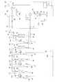
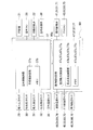
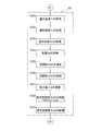
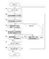
- the schematic block diagram of the air conditioner concerning one Embodiment of this invention The block diagram which shows the control part of an air conditioner.
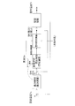
- the block diagram which shows the process for converging room temperature to preset temperature.
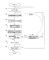
- Flow chart of capacity control The detailed flowchart at the time of the cooling operation in step S2 of FIG.
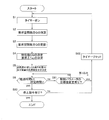
- the detailed flowchart at the time of heating operation in step S2 of FIG. 10 is a flowchart of capability control according to another embodiment 1; 10 is a flowchart of capability control according to another embodiment 2;
- FIG. 1 is a schematic configuration diagram of an air conditioner according to an embodiment of the present invention.
- the air conditioner 10 is a device that cools and heats a room such as a building by vapor compression refrigeration cycle operation.
- the air conditioner 10 includes one air conditioner outdoor unit 20, a plurality of (in this embodiment, four) air conditioner indoor units 40, 50, 60, and 70 connected in parallel thereto, the air conditioner outdoor unit 20, and the air conditioner.
- a liquid refrigerant communication pipe 81 and a gas refrigerant communication pipe 82 for connecting the indoor units 40, 50, 60, and 70 are provided.
- the refrigerant circuit 11 of the air conditioner 10 is configured by connecting an air conditioner outdoor unit 20, an air conditioner indoor unit 40, 50, 60, 70, a liquid refrigerant communication pipe 81 and a gas refrigerant communication pipe 82.
- Air conditioner indoor units 40, 50, 60, 70 are installed by embedding or hanging in a ceiling of a room such as a building or by hanging on a wall surface of the room.
- the air conditioning indoor unit 40 and the air conditioning indoor units 50, 60, and 70 have the same configuration, only the configuration of the air conditioning indoor unit 40 will be described here, and the configuration of the air conditioning indoor units 50, 60, and 70 will be described respectively.
- the reference numbers of the 50th, 60th, or 70th are attached in place of the 40th symbol indicating each part of the air conditioning indoor unit 40, and the description of each component is omitted.
- the air conditioning indoor unit 40 includes an indoor side refrigerant circuit 11a that forms part of the refrigerant circuit 11 (the indoor side refrigerant circuit 11b in the air conditioning indoor unit 50, the indoor side refrigerant circuit 11c in the air conditioning indoor unit 60, and the indoor side in the air conditioning indoor unit 70.
- the indoor refrigerant circuit 11a includes an indoor expansion valve 41 and an indoor heat exchanger 42.
- the indoor expansion valves 41, 51, 61, 71 are provided in the air conditioning indoor units 40, 50, 60, 70, respectively.
- an expansion mechanism (including an expansion valve). May be provided in the air conditioner outdoor unit 20, or may be provided in a connection unit independent of the air conditioner indoor units 40, 50, 60, 70 and the air conditioner outdoor unit 20.
- the indoor expansion valve 41 is an electric expansion valve.
- the indoor expansion valve 41 is connected to the liquid side of the indoor heat exchanger 42 in order to adjust the flow rate of the refrigerant flowing in the indoor refrigerant circuit 11a.
- the indoor expansion valve 41 can also block the passage of the refrigerant.
- the indoor heat exchanger 42 is a cross fin type fin-and-tube heat exchanger composed of heat transfer tubes and a large number of fins.
- the indoor heat exchanger 42 functions as a refrigerant evaporator during cooling operation to cool the room air, and functions as a refrigerant condenser during heating operation to heat the room air.
- the indoor heat exchanger 42 is a cross-fin type fin-and-tube heat exchanger, but is not limited thereto, and may be another type of heat exchanger.
- the air conditioning indoor unit 40 has an indoor fan 43.
- the indoor fan 43 sucks indoor air into the air-conditioning indoor unit 40, exchanges heat with the refrigerant in the indoor heat exchanger 42, and supplies the indoor air as supply air.
- the indoor fan 43 can change the air volume of the air supplied to the indoor heat exchanger 42 within a predetermined air volume range.
- the indoor fan 43 is a centrifugal fan, a multiblade fan or the like driven by a motor 43m made of a DC fan motor or the like.
- the air volume fixed mode and the air volume automatic mode can be selected via an input device such as a remote controller.
- the fixed air volume mode is a mode in which three types of fixed air volumes are set: a weak wind with the smallest air volume, a strong wind with the largest air volume, and a medium wind between the weak wind and the strong wind.
- the air volume automatic mode is a mode in which the air volume is automatically changed between a weak wind and a strong wind according to the degree of superheat SH or the degree of supercooling SC.
- the air volume fixing mode is set. If “automatic” is selected, it is automatically set according to the driving state. It becomes the air volume automatic mode in which the air volume is changed.
- the fan tap of the air volume of the indoor fan 43 is switched in three stages of “weak wind”, “medium wind”, and “strong wind”.
- the number of switching stages is not limited to three, but may be ten, for example.
- the air volume Ga of the indoor fan 43 is calculated by the number of rotations of the motor 43m.
- the calculation of the air volume Ga may be calculated based on the current value of the motor 43m, or may be calculated based on the set fan tap.
- the air conditioning indoor unit 40 is provided with various sensors.
- the liquid side temperature sensor 44 is provided on the liquid side of the indoor heat exchanger 42.
- the liquid side temperature sensor 44 detects the refrigerant temperature corresponding to the condensation temperature Tc in the heating operation or the refrigerant temperature corresponding to the evaporation temperature Te in the cooling operation.
- a gas side temperature sensor 45 is provided on the gas side of the indoor heat exchanger 42.
- the gas side temperature sensor 45 detects the temperature of the refrigerant.
- the indoor temperature sensor 46 is provided on the indoor air intake side of the air conditioning indoor unit 40.
- the indoor temperature sensor 46 detects the temperature of indoor air flowing into the air conditioning indoor unit 40 (that is, the indoor temperature Tr).
- the liquid side temperature sensor 44, the gas side temperature sensor 45, and the room temperature sensor 46 are composed of thermistors.
- FIG. 2 is a block diagram illustrating a control unit of the air conditioning indoor unit.
- the air conditioning indoor unit 40 includes an indoor side control unit 47.
- the indoor side control unit 47 controls the operation of each unit constituting the air conditioning indoor unit 40.
- the indoor control unit 47 includes an air conditioning capacity calculation unit 47a, a required temperature calculation unit 47b, and a memory 47c.
- the air conditioning capacity calculation unit 47a calculates the current air conditioning capacity and the like in the air conditioning indoor unit 40. Further, the required temperature calculation unit 47b calculates the required evaporation temperature Ter or the required condensation temperature Tcr necessary for the next performance based on the current air conditioning capability.
- the memories 47c, 57c, 67c, and 77c store various data.
- the indoor side control unit 47 communicates a control signal and the like with a remote controller (not shown) for individually operating the air conditioning indoor unit 40, and further transmits a transmission line with the air conditioning outdoor unit 20. Communication of control signals and the like is performed via 80a.
- Air conditioner outdoor unit 20 The air conditioning outdoor unit 20 is installed outside a building or the like, and is connected to the air conditioning indoor units 40, 50, 60, 70 via the liquid refrigerant communication pipe 81 and the gas refrigerant communication pipe 82. , 50, 60, and 70 constitute the refrigerant circuit 11.
- the air conditioning outdoor unit 20 includes an outdoor refrigerant circuit 11e that constitutes a part of the refrigerant circuit 11.
- the outdoor refrigerant circuit 11e includes a compressor 21, a four-way switching valve 22, an outdoor heat exchanger 23, an outdoor expansion valve 38, an accumulator 24, a liquid side closing valve 26, and a gas side closing valve 27. have.
- the compressor 21 is a variable capacity compressor, and the rotation of the motor 21m is controlled by an inverter. In the present embodiment, only one compressor 21 is provided, but the present invention is not limited to this, and two or more compressors may be connected in parallel according to the number of connected air conditioner indoor units.
- the four-way switching valve 22 is a valve that switches the direction of refrigerant flow. During the cooling operation, the four-way switching valve 22 connects the discharge side of the compressor 21 and the gas side of the outdoor heat exchanger 23, and at the same time, the suction side (specifically, the accumulator 24) of the compressor 21 and the gas refrigerant communication pipe. 82 side (cooling operation state: see the solid line of the four-way switching valve 22 in FIG. 1).
- the outdoor heat exchanger 23 functions as a refrigerant condenser
- the indoor heat exchangers 42, 52, 62, and 72 function as a refrigerant evaporator.
- the four-way switching valve 22 connects the discharge side of the compressor 21 and the gas refrigerant communication pipe 82 side and connects the suction side of the compressor 21 and the gas side of the outdoor heat exchanger 23 (heating). Operation state: (Refer to the broken line of the four-way selector valve 22 in FIG. 1).
- the indoor heat exchangers 42, 52, 62, and 72 function as a refrigerant condenser
- the outdoor heat exchanger 23 functions as a refrigerant evaporator.
- Outdoor heat exchanger 23 is a cross-fin type fin-and-tube heat exchanger.
- the present invention is not limited to this, and other types of heat exchangers may be used.
- the outdoor heat exchanger 23 functions as a refrigerant condenser during the cooling operation, and functions as a refrigerant evaporator during the heating operation.
- the outdoor heat exchanger 23 has a gas side connected to the four-way switching valve 22 and a liquid side connected to the outdoor expansion valve 38.
- Outdoor expansion valve 38 is an electric expansion valve, and adjusts the pressure and flow rate of the refrigerant flowing in the outdoor refrigerant circuit 11e.
- the outdoor expansion valve 38 is disposed downstream of the outdoor heat exchanger 23 in the refrigerant flow direction in the refrigerant circuit 11 during the cooling operation.
- Outdoor fan 28 blows the sucked outdoor air to the outdoor heat exchanger 23 to exchange heat with the refrigerant.
- the outdoor fan 28 can vary the amount of air that is blown to the outdoor heat exchanger 23.
- the outdoor fan 28 is a propeller fan or the like, and is driven by a motor 28m composed of a DC fan motor or the like.
- liquid side closing valve 26 and gas side closing valve 27 are valves provided at connection ports with the liquid refrigerant communication pipe 81 and the gas refrigerant communication pipe 82.
- the liquid side shut-off valve 26 is arranged downstream of the outdoor expansion valve 38 and upstream of the liquid refrigerant communication pipe 81 in the refrigerant flow direction in the refrigerant circuit 11 during the cooling operation.
- the gas side closing valve 27 is connected to the four-way switching valve 22. The liquid side closing valve 26 and the gas side closing valve 27 can block the passage of the refrigerant.
- the air conditioning outdoor unit 20 is provided with a suction pressure sensor 29, a discharge pressure sensor 30, a suction temperature sensor 31, a discharge temperature sensor 32, and an outdoor temperature sensor.
- the suction pressure sensor 29 detects the suction pressure of the compressor 21.
- the suction pressure is a refrigerant pressure corresponding to the evaporation pressure Pe in the cooling operation.
- the discharge pressure sensor 30 detects the discharge pressure of the compressor 21.
- the discharge pressure is a refrigerant pressure corresponding to the condensation pressure Pc in the heating operation.
- the suction temperature sensor 31 detects the suction temperature of the compressor 21. Further, the discharge temperature sensor 32 detects the discharge temperature of the compressor 21.
- the outdoor temperature sensor 36 detects the temperature of outdoor air flowing into the air-conditioning outdoor unit 20 (hereinafter referred to as outdoor temperature) on the outdoor air inlet side of the air-conditioning outdoor unit 20.
- the suction temperature sensor 31, the discharge temperature sensor 32, and the outdoor temperature sensor 36 are thermistors.
- Outdoor control unit 37 As shown in FIG. 2, the air-conditioning outdoor unit 20 has an outdoor control unit 37.
- the outdoor side control unit 37 includes a target value determination unit 37a, a memory 37b, an inverter circuit (not shown), and the like.
- the target value determination unit 37a determines the target evaporation temperature Tet or the target condensation temperature Tct.
- the memory 37b stores various data.
- the outdoor side control unit 37 communicates control signals and the like with the indoor side control units 47, 57, 67, and 77 of the air conditioning indoor units 40, 50, 60, and 70 via the transmission line 80a.
- Control unit 80 includes indoor side control units 47, 57, 67, 77, an outdoor side control unit 37, and a transmission line 80a.
- the control unit 80 is connected to various sensors and controls various devices based on detection signals from the various sensors.
- the refrigerant communication pipes 81 and 82 are refrigerant pipes that are constructed on site when the air conditioner 10 is installed at an installation location such as a building. Since the refrigerant communication pipes 81 and 82 have various lengths and pipe diameters depending on the installation conditions such as the installation location and the combination of the air conditioner outdoor unit and the air conditioner indoor unit, when the air conditioner 10 is installed, An appropriate amount of refrigerant is filled according to the installation conditions such as the length of the refrigerant communication pipes 81 and 82 and the pipe diameter.
- FIG. 3 is a block diagram showing a process for converging the room temperature to the set temperature. 2 and 3, the indoor side control units 47, 57, 67, 77 determine the target value of the superheat degree SH or the supercooling degree SC in the capacity control so that the indoor temperature Tr becomes the set temperature Ts. Specifically, a target value of superheat degree SH (hereinafter referred to as superheat degree target value SHt) or a target value of supercooling degree SC (hereinafter referred to as supercooling degree target value SCt) for realizing necessary air conditioning capacity with energy saving. Is calculated).
- superheat degree target value SHt a target value of supercooling degree SC
- supercooling degree target value SCt a target value for realizing necessary air conditioning capacity with energy saving. Is calculated).
- the indoor side control units 47, 57, 67, 77 calculate the opening degree of the indoor expansion valves 41, 51, 61, 71 based on the superheat degree target value SHt or the supercooling degree target value SCt. Control is performed so that the openings of the expansion valves 41, 51, 61, 71 are the openings obtained by calculation.
- the degree of superheat SH or the degree of supercooling SC increases or decreases according to the opening degree of the indoor expansion valves 41, 51, 61, 71, and energy supplied from the indoor heat exchangers 42, 52, 62, 72 to the air-conditioned space ( As the amount of heat exchange increases or decreases, a change appears such that the room temperature approaches the set temperature.
- the detected value of the room temperature Tr is input to the “capability calculation” process of capability control.
- FIG. 4 is a flowchart of capability control.
- the indoor side control units 47, 57, 67, 77 turn on the timer in step S1, and proceed to step S2.
- the indoor side control units 47, 57, 67, 77 calculate the required air conditioning capability Q in step S2.
- the required air conditioning capability Q is a capability of calculating the current air conditioning capability of the air conditioning indoor units 40, 50, 60, 70 and indicating whether the current air conditioning capability is excessive or insufficient based on the temperature difference between the indoor temperature Tr and the set temperature Ts. Calculated by calculating the difference ⁇ Q and adding it to the current air conditioning capability.
- the indoor control units 47, 57, 67, 77 update the previous required air conditioning capability Q to the newly calculated required air conditioning capability Q in step S3.
- the indoor side control units 47, 57, 67, 77 have predetermined characteristics based on the required air conditioning capability Q and the latest target evaporation temperature Tet or target condensation temperature Tct acquired from the outdoor side control unit 37 in step S4.
- the value CQ and the request ⁇ Tec to be transmitted to the outdoor side control unit 37 are determined.
- a characteristic value CQ a value indicating the product of the term g (G) and the term h (SCH) that can be freely controlled by the air conditioning indoor units 40, 50, 60, 70, that is, g (G) ⁇ h (SCH).
- the air conditioning indoor units 40, 50, 60, and 70 cannot freely control the target evaporation temperature Tet or the target condensation temperature Tct, but in order to realize the required air conditioning capability Q with more energy saving, the outdoor side control unit 37
- the evaporation temperature Te or the condensation temperature Tc which is different from the target evaporation temperature Tet or the target condensation temperature Tct given from the above, is calculated.
- the difference between the indoor temperature Tr and the calculated evaporation temperature Te or condensation temperature Tc is determined as the request ⁇ Tec and transmitted to the outdoor control unit 37.
- the method for determining the required ⁇ Tec is described in detail in Patent Document 1 (Japanese Patent Laid-Open No. 2011-257126) cited in the “Background Art” section, and thus the description thereof is omitted here.
- the indoor side control units 47, 57, 67, 77 have the highest refrigerant side heat transfer coefficient among the combinations of the terms g (G) and h (SCH) that satisfy the characteristic value CQ in step S5.
- the term h (SCH) is determined, and the superheat degree SH or the supercooling degree SC at that time is set as the superheat degree target value SHt or the supercooling degree target value SCt.
- the remaining term g (G) is automatically determined from the characteristic value CQ and the previously determined term h (SCH).
- step S6 the indoor side control units 47, 57, 67, and 77 determine whether or not the elapsed time t from the start of the time has reached a predetermined time t1 (for example, 3 minutes), When t ⁇ t1, the process proceeds to step S7, and when t ⁇ t1, the process proceeds to step S61.
- a predetermined time t1 for example, 3 minutes
- step S7 the indoor side control units 47, 57, 67, 77 reset the timer in step S7, and proceed to step S8.
- indoor side control part 47,57,67,77 determines whether there existed the stop command of operation in step S8, and when there was no stop command, it returns to step S1.
- the capacity control is a control for updating the required air conditioning capacity periodically (for example, every 3 minutes) in order to converge the room temperature Tr to the set temperature Ts.
- the target evaporation temperature Tet or the target condensing temperature Tct, the superheat degree target value SHt or the supercooling degree target value SCt, or the airflow setting value is set by the indoor side control units 47, 57, 67, 77. If it is changed to an unintended value, the control of periodically updating the required air conditioning capability Q as described above will cause the room temperature Tr to deviate from the target value until the required air conditioning capability Q is updated, and the comfort level There is a risk of lowering the control stability.
- the indoor control units 47, 57, 67, 77 change the target evaporation temperature Tet or the target condensing temperature Tct, the superheat degree target value SHt or the supercooling degree target value SCt, or the air volume setting value.
- interrupt capability control is employed in which an appropriate requested air conditioning capability Q is interrupted and updated without waiting for the periodic calculation of the required air conditioning capability Q. That is after step S61.
- step S6 when the indoor side control units 47, 57, 67, 77 determine in step S6 that the elapsed time t has not yet reached a predetermined time t1 (for example, 3 minutes), the control proceeds to step S61. It is determined whether or not the parameter target value has been changed.
- a predetermined time t1 for example, 3 minutes
- the indoor-side control units 47, 57, 67, and 77 have changed in the target evaporation temperature Tet or the target condensation temperature Tct, the superheat degree target value SHt or the supercooling degree target value SCt, or the air volume setting value. If there is any change, the process returns to step S2 to calculate the required air conditioning capacity based on the target value of the changed control parameter, and the previous required air conditioning capacity is newly calculated in step S3. Update to the required air conditioning capacity.
- the room temperature Tr is prevented from deviating from the target value before the required air conditioning capability is updated.
- the four-way switching valve 22 connects the discharge side of the compressor 21 and the gas side of the outdoor heat exchanger 23, and the suction side of the compressor 21 and the indoor heat exchanger.
- the gas side of 42, 52, 62, 72 is connected (state shown by the solid line in FIG. 1).
- each indoor expansion valve 41, 51, 61, 71 is adjusted so that the superheat degree SH of the refrigerant at the refrigerant outlet of the indoor heat exchangers 42, 52, 62, 72 becomes constant at the superheat degree target value SHt.
- the superheat target value SHt is set to an optimum value so that the room temperature Tr converges to the set temperature Ts within a predetermined superheat range.
- the superheat degree SH of the refrigerant at the refrigerant outlets of the indoor heat exchangers 42, 52, 62, 72 is determined from the values detected by the gas side temperature sensors 45, 55, 65, 75 from the liquid side temperature sensors 44, 54. , 64, 74 are subtracted from the detected values (corresponding to the evaporation temperature Te).
- the superheat degree SH of the refrigerant at the outlets of the indoor heat exchangers 42, 52, 62, and 72 is not limited to the above-described method, and the suction pressure of the compressor 21 detected by the suction pressure sensor 29 is determined based on the evaporation temperature Te. May be calculated by subtracting the saturation temperature value from the detection values by the gas side temperature sensors 45, 55, 65, 75.
- a temperature sensor for detecting the temperature of the refrigerant flowing in each indoor heat exchanger 42, 52, 62, 72 is provided, and the evaporation temperature Te detected by this temperature sensor is set.
- the superheat degree SH of the refrigerant at the outlet of each indoor heat exchanger 42, 52, 62, 72 is detected. It may be.
- the low-pressure gas refrigerant is sucked into the compressor 21 and compressed to be combined with the high-pressure gas refrigerant.
- the high-pressure gas refrigerant is sent to the outdoor heat exchanger 23 via the four-way switching valve 22, exchanges heat with the outdoor air supplied by the outdoor fan 28, and condenses to form a high-pressure liquid refrigerant.
- the high-pressure liquid refrigerant is sent to the air conditioning indoor units 40, 50, 60, and 70 via the liquid side closing valve 26 and the liquid refrigerant communication pipe 81.
- the high-pressure liquid refrigerant sent to the air-conditioning indoor units 40, 50, 60, 70 is decompressed to near the suction pressure of the compressor 21 by the indoor expansion valves 41, 51, 61, 71 and is in a low-pressure gas-liquid two-phase state.
- the refrigerant is sent to the indoor heat exchangers 42, 52, 62, and 72, exchanges heat with indoor air in the indoor heat exchangers 42, 52, 62, and 72, and evaporates to become a low-pressure gas refrigerant.
- This low-pressure gas refrigerant is sent to the air-conditioning outdoor unit 20 via the gas refrigerant communication pipe 82 and flows into the accumulator 24 via the gas-side closing valve 27 and the four-way switching valve 22. Then, the low-pressure gas refrigerant that has flowed into the accumulator 24 is again sucked into the compressor 21.
- the air conditioner 10 can perform a cooling operation in which the outdoor heat exchanger 23 functions as a refrigerant condenser and the indoor heat exchangers 42, 52, 62, and 72 function as a refrigerant evaporator.
- the evaporation pressure Pe in all the indoor heat exchangers 42, 52, 62, 72 is a common pressure.
- FIG. 5 is a detailed flowchart of the cooling operation in step S2 of FIG.
- a description will be given with reference to FIGS.
- the indoor side control units 47, 57, 67, 77 acquire the current indoor temperature Tr via the indoor temperature sensors 46, 56, 66, 76 in step S201.
- the indoor side control units 47, 57, 67, 77 acquire the current evaporation temperature Te via the liquid side temperature sensors 44, 54, 64, 74 in step S202.
- the indoor side control units 47, 57, 67, 77 subtract the corresponding evaporation temperature Te acquired in step S202 from the detection values of the gas side temperature sensors 45, 55, 65, 75 in step S203.
- the superheat degree SH at the present time is acquired.
- step S204 the indoor side control units 47, 57, 67, 77 acquire the air volume Ga by the indoor fans 43, 53, 63, 73 at the current time.
- the indoor side control units 47, 57, 67, and 77 are temperatures that are the temperature difference between the current indoor temperature Tr and the evaporation temperature Te through the air conditioning capability calculation units 47a, 57a, 67a, and 77a in step S205.
- the current air conditioning capability Q1 in the air conditioning indoor units 40, 50, 60, 70 is calculated.
- the air conditioning capability Q1 may be calculated by employing the evaporation temperature Te instead of the temperature difference [ ⁇ T].
- the indoor side control units 47, 57, 67, 77 store the air conditioning capability Q1 in the memories 47c, 57c, 67c, 77c in step S206.
- step S207 the indoor side control units 47, 57, 67, and 77 are set by the remote controller or the like with the room temperature Tr and the current user via the air conditioning capability calculation units 47a, 57a, 67a, and 77a. From the temperature difference with the set temperature Ts, a capacity difference ⁇ Q indicating whether the air conditioning capacity Q1 in the indoor space is excessive or insufficient is calculated.
- the indoor side control units 47, 57, 67, and 77 obtain the required air conditioning capability Q2 by adding the capability difference ⁇ Q to the air conditioning capability Q1 stored in step S208.
- the indoor control units 47, 57, 67, and 77 store the required air conditioning capability Q2 in the memories 47c, 57c, 67c, and 77c in step S209.
- step S3 of FIG. 4 the previous required air conditioning capability Q2 is updated to the new required air conditioning capability Q2 stored in step S209.
- the characteristic value CQ is determined in step S4 of FIG.
- the characteristic value CQ is determined by the degree of superheat SH and the air volume, an optimal combination should be determined for realizing energy saving, and this determination is performed in step S5.
- the characteristic value CQ is the product of the term g (G) and the term h (SCH) that can be freely controlled by the air conditioning indoor units 40, 50, 60, and 70. Since the values are shown, there are innumerable combinations of the superheat degree SH and the air volume that realize the characteristic value CQ.
- the air conditioning indoor units 40, 50, 60, and 70 determine a combination in which the refrigerant side heat transfer coefficient is higher.
- the indoor side control units 47, 57, 67, 77 have the superheat degree lower limit value in the superheat degree settable range in the air volume automatic mode. If there is an air volume capable of realizing the characteristic value CQ with SHmin, the air volume is combined.
- the lower limit SHmin is an optimum value for the superheat degree SH, since the risk of wetting increases when the air volume varies with the lower limit value, a superheat degree higher than the lower limit may be set even during cooling operation from the viewpoint of reliability. is there.
- the indoor side control units 47, 57, 67, and 77 when there is no air volume that can realize the characteristic value CQ with the superheat lower limit SHmin within the superheat degree setting range, If the superheat degree SH capable of realizing the characteristic value CQ at the lower limit of the air volume is selected and determined from the superheat degree settable range, and there is an air volume capable of realizing the characteristic value CQ with the determined superheat degree SH, Combine air volume.
- the superheat degree SH that realizes the characteristic value CQ is uniquely determined by the fixed air volume.
- the indoor side control units 47, 57, 67, 77 use the superheat degree SH determined in step S5 as the superheat degree target value SHt, and the indoor heat exchanger
- the opening degree of each indoor expansion valve 41, 51, 61, 71 is adjusted so that the superheat degree SH of the refrigerant at the refrigerant outlets 42, 52, 62, 72 becomes the superheat degree target value SHt.
- the indoor control units 47, 57, 67, and 77 next update the required air conditioning capability Q2 after a predetermined time t1 (for example, 3 minutes) from the latest update, but within the predetermined time t1, the target evaporation temperature is updated.
- a predetermined time t1 for example, 3 minutes
- the target evaporation temperature is updated.
- the required air conditioning capability Q2 is calculated and updated without waiting for the elapse of the predetermined time t1. This is the interrupt capability control in the cooling operation.
- the interrupt capability control is performed on the indoor side when some protection control is activated and the superheat target value SHt has to be changed, or when the air volume is fixed.
- the control units 47, 57, 67, and 77 perform steps S2 to S4 in FIG. 4 to combine the superheat and the air volume that can realize the newly determined characteristic value QC.
- the term f ( ⁇ T) of Q2 f ( ⁇ T) ⁇ g (G) ⁇ h (SCH) even if there is no substantial change in the required air conditioning capacity Q2 before and after the update. Changes, the characteristic value CQ which is g (G) ⁇ h (SCH) also changes.
- the indoor side control units 47, 57, 67, 77 achieve the characteristic value CQ at the superheat degree lower limit value SHmin within the superheat degree setting range in the air volume automatic mode. If there is an air volume that can be achieved, combine that air volume. When there is no air volume that can realize the characteristic value CQ with the superheat degree lower limit value SHmin, the superheat degree SH that can realize the characteristic value CQ with the air volume lower limit value is selected from the superheat degree setting range.
- the required air conditioning capacity Q2 before and after the update does not substantially change, and the term f ( ⁇ T) does not change, so the value of the characteristic value CQ
- the superheat degree SH that can achieve the characteristic value CQ with the air volume fixed is determined, and becomes the superheat degree target value SHt.
- the indoor side control units 47, 57, 67, 77 increase the term f ( ⁇ T) to a necessary size.
- the evaporating temperature to be requested (required evaporating temperature Ter) is transmitted to the outdoor control unit 37.
- the capacity control for updating the required air conditioning capacity Q2 is performed every predetermined time t1, and the target evaporation temperature Tet is reached within the predetermined time t1.
- the interrupt ability control is performed to prevent the room temperature Tr from deviating from the target value before the required air conditioning ability Q2 is updated. is doing.
- the four-way switching valve 22 connects the discharge side of the compressor 21 and the gas side of the indoor heat exchangers 42, 52, 62, 72, and the compressor 21
- the suction side and the gas side of the outdoor heat exchanger 23 are connected (state shown by a broken line in FIG. 1).
- the opening degree of the outdoor expansion valve 38 is adjusted so as to reduce the pressure of the refrigerant flowing into the outdoor heat exchanger 23 to a pressure at which the refrigerant can be evaporated in the outdoor heat exchanger 23 (that is, the evaporation pressure Pe).
- the liquid side closing valve 26 and the gas side closing valve 27 are in an open state.
- the opening degree of the indoor expansion valves 41, 51, 61, 71 is adjusted so that the subcooling degree SC of the refrigerant at the outlets of the indoor heat exchangers 42, 52, 62, 72 is constant at the supercooling degree target value SCt.
- the supercooling degree target value SCt is set to an optimum temperature value so that the room temperature Tr converges to the set temperature Ts within the supercooling degree range specified according to the operation state at that time.
- the degree of refrigerant supercooling SC at the outlets of the indoor heat exchangers 42, 52, 62, 72 is the saturation corresponding to the condensation temperature Tc, the discharge pressure Pd of the compressor 21 detected by the discharge pressure sensor 30. It is detected by converting to a temperature value and subtracting the refrigerant temperature value detected by the liquid side temperature sensors 44, 54, 64, 74 from the saturation temperature value of this refrigerant.
- a temperature sensor for detecting the temperature of the refrigerant flowing in each indoor heat exchanger 42, 52, 62, 72 is provided and corresponds to the condensation temperature Tc detected by this temperature sensor.
- the subcooling degree SC of the refrigerant at the outlets of the indoor heat exchangers 42, 52, 62, 72 is detected by subtracting the refrigerant temperature value from the refrigerant temperature values detected by the liquid side temperature sensors 44, 54, 64, 74. You may make it do.
- the compressor 21, the outdoor fan 28, and the indoor fans 43, 53, 63, 73 are operated in the state of the refrigerant circuit 11, the low-pressure gas refrigerant is sucked into the compressor 21 and compressed to become a high-pressure gas refrigerant.
- the air-conditioning indoor units 40, 50, 60, 70 are sent via the four-way switching valve 22, the gas-side closing valve 27, and the gas refrigerant communication pipe 82.
- the high-pressure gas refrigerant sent to the air-conditioning indoor units 40, 50, 60, and 70 is condensed by exchanging heat with indoor air in the indoor heat exchangers 42, 52, 62, and 72 to become high-pressure liquid refrigerant. Then, when passing through the indoor expansion valves 41, 51, 61, 71, the pressure is reduced according to the opening degree of the indoor expansion valves 41, 51, 61, 71.
- the refrigerant that has passed through the indoor expansion valves 41, 51, 61, 71 is sent to the air conditioning outdoor unit 20 via the liquid refrigerant communication pipe 81, and further depressurized via the liquid side closing valve 26 and the outdoor expansion valve 38. Then, it flows into the outdoor heat exchanger 23.
- the low-pressure gas-liquid two-phase refrigerant flowing into the outdoor heat exchanger 23 exchanges heat with the outdoor air supplied by the outdoor fan 28 to evaporate into a low-pressure gas refrigerant, and passes through the four-way switching valve 22. And flows into the accumulator 24.
- the low-pressure gas refrigerant that has flowed into the accumulator 24 is again sucked into the compressor 21.
- the condensing pressure Pc in all the indoor heat exchangers 42, 52, 62, 72 Is a common pressure.
- FIG. 6 is a detailed flowchart of the heating operation in step S2 of FIG.
- a description will be given with reference to FIGS. 2 to 4 and FIG.
- the indoor side control units 47, 57, 67, and 77 acquire the current indoor temperature Tr through the indoor temperature sensors 46, 56, 66, and 76 in step S251.
- the indoor side control units 47, 57, 67, 77 obtain the current condensation temperature Tc via the liquid side temperature sensors 44, 54, 64, 74 in step S252.
- the indoor side control units 47, 57, 67, 77 convert the detection value of the discharge pressure sensor 30 into a saturation temperature value corresponding to the condensation temperature Tc in step S253, and the liquid side temperature sensor 44 from this saturation temperature value. , 54, 64, and 74 are subtracted from the detected values to obtain the degree of supercooling SC at the present time.
- step S254 the indoor side control units 47, 57, 67, 77 acquire the air volume Ga by the indoor fans 43, 53, 63, 73 at the current time.
- the indoor side control units 47, 57, 67, and 77 are temperatures that are the temperature difference between the current indoor temperature Tr and the condensation temperature Tc via the air conditioning capability calculation units 47a, 57a, 67a, and 77a in step S255.
- the current air conditioning capability Q3 in the air conditioning indoor units 40, 50, 60, 70 is calculated.
- the air conditioning capability Q3 may be calculated by employing the condensation temperature Tc instead of the temperature difference ⁇ T.
- the indoor side control units 47, 57, 67, 77 store the air conditioning capability Q3 in the memories 47c, 57c, 67c, 77c in step S256.
- step S257 the indoor side control units 47, 57, 67, and 77 are set by the remote controller or the like with the indoor temperature Tr and the current user via the air conditioning capability calculation units 47a, 57a, 67a, and 77a. From the temperature difference with the set temperature Ts, a capacity difference ⁇ Q indicating the excess or deficiency of the air conditioning capacity Q3 in the indoor space is calculated.
- the indoor side control units 47, 57, 67, 77 obtain the required air conditioning capacity Q4 by adding the capacity difference ⁇ Q to the air conditioning capacity Q3 in step S258.
- the indoor side control units 47, 57, 67, 77 store the required air conditioning capability Q4 in the memories 47c, 57c, 67c, 77c in step S259.
- step S3 of FIG. 4 the previous required air conditioning capability Q4 is updated to the new required air conditioning capability Q4 stored in step S259.
- the characteristic value CQ is determined in step S4 of FIG.
- the characteristic value CQ is determined by the degree of supercooling SC and the air volume, an optimal combination should be determined for realizing energy saving, and this determination is performed in step S5.
- the characteristic value CQ is the product of the terms g (G) and h (SC) that can be freely controlled by the air conditioning indoor units 40, 50, 60, and 70. Since these are the values shown, there are innumerable combinations of the degree of supercooling SC and the air volume that realize the characteristic value CQ.
- the air conditioning indoor units 40, 50, 60, and 70 determine a combination in which the refrigerant side heat transfer coefficient is higher.
- the indoor-side control units 47, 57, 67, and 77 combine airflows capable of realizing the characteristic value CQ with the optimum supercooling value within the supercooling degree setting range in the airflow automatic mode. Since the optimum value of the degree of supercooling SC depends on conditions such as ⁇ T and always fluctuates, the optimum air volume is combined each time.
- the indoor control units 47, 57, 67, and 77 use the optimum supercooling degree determined in step S5 as the supercooling degree target value SCt.
- the opening degree of each indoor expansion valve 41, 51, 61, 71 is adjusted so that the supercooling degree SC of the refrigerant at the refrigerant outlet of the heat exchangers 42, 52, 62, 72 becomes the supercooling degree target value SCt.
- the indoor control units 47, 57, 67, 77 next update the required air conditioning capability Q4 after a predetermined time (for example, 3 minutes) after the latest update, but within the predetermined period, the target condensation temperature Tct,
- a predetermined time for example, 3 minutes
- the required air conditioning capability Q4 is calculated and updated without waiting for the elapse of a predetermined period. This is the interrupt capability control in the heating operation.
- the interrupt capability control is performed when the protection control is activated and the supercooling degree target value SCt has to be changed, or when the air volume is fixed.
- the control units 47, 57, 67, and 77 perform steps S2 to S4 in FIG. 4 to combine the degree of supercooling and the air volume that can realize the newly determined characteristic value QC.
- the term f ( ⁇ T) of Q4 f ( ⁇ T) ⁇ g (G) ⁇ h (SC) even if the required air conditioning capacity Q4 before and after the update is not substantially changed.
- the characteristic value CQ which is g (G) ⁇ h (SC) also changes.
- the indoor side control units 47, 57, 67, 77 realize the characteristic value CQ with the supercooling degree optimum value within the subcooling degree setting range in the air volume automatic mode. If there is an air volume that can be achieved, combine the air volume. Since the optimum value of the degree of supercooling SC always fluctuates, the optimum value of supercooling is selected and determined each time, and the air volume capable of realizing the characteristic value CQ with the determined degree of supercooling SC is combined.
- the required air conditioning capacity Q4 before and after the update is not substantially changed, and the term f ( ⁇ T) is not changed.
- the supercooling degree SC at which the characteristic value CQ can be realized with the air flow fixed is determined, and this value becomes the supercooling degree target value SCt.
- the indoor side control units 47, 57, 67, 77 set the term f ( ⁇ T) to a required size.
- the condensation temperature to be requested (required condensation temperature Tcr) is transmitted to the outdoor control unit 37.
- the capacity control for updating the required air conditioning capacity Q4 is performed every predetermined time t1, and the target condensation temperature Tct is determined within the predetermined time t1.
- the interrupting capacity control is performed, so that the room temperature Tr deviates from the target value before the required air conditioning capacity Q4 is updated. It is preventing.
- the air conditioning indoor units 40, 50, 60, 70 have indoor side control units 47, 57, 67, 77.
- the indoor side control units 47, 57, 67, 77 are based on the target evaporation temperature Tet or the target condensation temperature Tct set by the air-conditioning outdoor unit 20, and the superheat degree target value SHt or the supercooling degree target value SCt,
- the air volume Ga is determined, each air conditioning indoor unit can realize a stable air conditioning operation regardless of the status of other air conditioning indoor units.
- the indoor side control units 47, 57, 67, and 77 optimize the degree of superheating or the degree of supercooling so that the refrigerant side heat transfer coefficient is increased in the capacity control. In addition to avoiding deviation from the value, the air volume can be minimized and energy is saved.
- the indoor side control units 47, 57, 67, 77 transmit the required evaporation temperature to the air conditioning outdoor unit 20.
- the air-conditioning outdoor unit 20 uses the evaporation temperature Te that needs to increase the operating frequency of the compressor 21 most as the target evaporation temperature among the evaporation temperatures Te requested from the indoor side control units 47, 57, 67, 77. All the indoor side control units 47, 57, 67, 77 do not meet the requirements.
- a certain indoor side control unit requests a severe (lower) evaporating temperature Te in order to solve the shortage of capacity, if it is lower than the evaporating temperature Te requested by another indoor side control unit, it is requested.
- the evaporating temperature becomes the target evaporating temperature, and the capacity control as expected of the indoor control unit can be performed.
- the indoor side control units 47, 57, 67, and 77 perform capacity control when there is a change in the superheat degree target value SHt or the supercooling degree target value SCt, the air flow setting value, the target evaporation temperature Tet, or the target condensation temperature Tct.
- Interrupt capability control that interrupts and calculates and updates the requested capability without waiting for a regular calculation. As a result, the room temperature Tr is prevented from deviating from the target value.
- the indoor side control units 47, 57, 67, 77 optimize the degree of superheating or the degree of supercooling so that the refrigerant side heat transfer coefficient is increased in the interrupt capability control, so that the room temperature Tr deviates from the target value. In addition, the air volume can be minimized and energy is saved.
- the indoor side control units 47, 57, 67, and 77 require evaporation required for the air conditioner outdoor unit 20 in order to minimize the temperature difference between the indoor temperature Tr and the evaporation temperature Te or the condensation temperature Tc in the interrupt capability control.
- the temperature Ter or the required condensation temperature Tcr is calculated.
- the required evaporation temperature Ter or the required condensation temperature Tcr obtained for the air-conditioning outdoor unit 20 is not necessarily reflected in the next target evaporation temperature Tet or the target condensation temperature Tct, but the required evaporation temperature obtained by another indoor control unit. Although Ter or the required condensation temperature Tcr may be reflected, the entire system including the outdoor unit saves energy.
- the indoor side control units 47, 57, 67, and 77 change the superheat degree target value SHt or the supercool degree target value SCt in the control other than their own capacity control, or the superheat degree target value SHt from the air conditioner outdoor unit 20.
- interrupt capability control is executed to prevent the room temperature from deviating from the target value.
- the indoor side control units 47, 57, 67, and 77 execute the interrupt capability control and prevent the indoor temperature Tr from deviating from the target value.
- the detection value of the liquid side temperature sensor 44, 54, 64, 74 is substituted for the liquid pipe temperature Th2.
- the operation amount may be adjusted so that the actuator does not fluctuate excessively. This is to avoid a large change of the actuator at a time from the viewpoint of user comfort.
- the operation is performed by 50% of the necessary operation amount to completely maintain the capability. Specifically, in the calculation, even if the air volume is “strong wind”, it is limited to “medium wind”.
- the interrupt capability control is interrupted before step S2 in FIG. 4.
- the present invention is not limited to this.
- the interrupt capability control is performed before step S4. It may be interrupted.
- the interrupt capability control is interrupted before step S4, so that the calculation of the required air conditioning capability Q may be omitted and only the characteristic value CQ may be calculated.
- step S7 in FIG. 4 is deleted, and step 8 in FIG. 4 is moved up to step S60. This eliminates the waste that the required air conditioning capability Q is updated by the periodic capability control immediately after the required air conditioning capability Q is updated by the interrupt capability control.
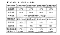
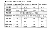
- FIG. 9A shows the room temperature of each air-conditioning target space and the air volume of each air-conditioned indoor unit when the system has insufficient capacity. And a table showing evaporation temperatures.
- FIG. 9B is a table showing the room temperature of each air conditioning target space, the air volume of each air conditioning indoor unit, and the evaporation temperature when an ideal state is realized as a system from the viewpoint of energy saving.
- FIG. 9A it is assumed that air-conditioning indoor units A, B, C, and D are installed.
- the air conditioning indoor units A, B, C, and D correspond to the air conditioning indoor units 40, 50, 60, and 70 in FIG.
- the set temperature of the air conditioning indoor units A, B, C, and D is 27 ° C.
- the indoor side control units 47, 57, 67, and 77 are the latest target evaporation temperature given from the required air conditioning capability Q and the outdoor side control unit 37 via the air conditioning capability calculation units 47a, 57a, 67a, and 77a. Based on Tet, a predetermined characteristic value CQ and a request ⁇ Te to be transmitted to the outdoor control unit 37 are determined.
- the required air-conditioning capacity Q includes a term f ( ⁇ T) determined by the difference ⁇ T between the room temperature Tr and the target evaporation temperature Tet, a term g (G) determined by the air volume G, and a term h (SH) determined by the superheat degree SH.
- the actual room temperature is 28 ° C.
- it is necessary to increase the value of the term f ( ⁇ T) of the heat exchange function, that is, to lower the evaporation temperature, and the evaporation temperature to be requested is 9 ° C.
- the indoor side control unit 67 changes the air flow rate Ga from 85% to 100% at the present time, and term g (G) ⁇ term h (SH) of the heat exchange function It is possible to increase the value of and to reduce the value of the term f ( ⁇ T) accordingly.
- the indoor side control unit 77 changes the air flow rate Ga from 80% to 100% from the current 80% based on the same concept as the air conditioning indoor unit C60. It is possible to increase the value of (G) ⁇ term h (SH) and try to decrease the value of term f ( ⁇ T) accordingly.
- the air conditioning indoor unit B50 may have an excessive capacity due to the evaporation temperature Te being lowered to 9 ° C. Therefore, the indoor side control unit 57 reduces the value of the term g (G) ⁇ the term h (SH) by reducing the air volume Ga to 90% by the amount of the increase in the value of the term f ( ⁇ T) of the heat exchange function, and air conditioning. Stabilize ability Q1b.
- the indoor side control unit 57 further reduces the value of the term f ( ⁇ T) of the heat exchange function and changes the air flow rate Ga from 90% to 100% in order to maintain the current capacity with energy saving, and the term g ( G) x can be attempted to increase the value of the term h (SH).
- the air-conditioning indoor unit C60 may also have an excessive capacity due to the evaporation temperature Te being reduced to 9 ° C. Therefore, the indoor side control unit 67 reduces the value of the term g (G) ⁇ the term h (SH) by reducing the air volume Ga to 75% by the amount of the increase in the value of the term f ( ⁇ T) of the heat exchange function, and air conditioning. Stabilize ability Q1c.
- the indoor side control unit 67 reduces the value of the term f ( ⁇ T) of the heat exchange function and reduces the air volume Ga to 75 at the current time by the same concept as the air conditioning indoor unit B50. It can be attempted to increase the value of term g (G) ⁇ term h (SH) by changing from% to 100%.
- the air conditioning indoor unit D70 may also have excessive capacity due to the evaporation temperature Te being reduced to 9 ° C. Therefore, the indoor side control unit 77 reduces the value of the term g (G) ⁇ the term h (SH) by reducing the air volume Ga to 70% by the amount of the increase in the value of the term f ( ⁇ T) of the heat exchange function, and air conditioning. Stabilize ability Q1d.
- the indoor side control unit 77 further reduces the value of the term f ( ⁇ T) ⁇ term h (SH) of the heat exchange function to reduce the value of the air flow amount Ga to 100% in order to maintain the current capacity with energy saving. ) ⁇ term h (SH) can be attempted to increase.
- the outdoor control unit 37 reduces the evaporation temperature to 9 ° C., thereby increasing the capacity of the air conditioning indoor unit A40 and maintaining the air volume at 100%.
- the room temperature drops to the set temperature of 27 ° C.
- the interrupt capability control works and before the capacity becomes excessive (the room temperature decreases) Reduce air volume and keep room temperature stable.
- a request ⁇ Te is transmitted again to the outdoor control unit 37.
- the air conditioning indoor unit A in which the air conditioning load factor with respect to the rated capacity is the maximum is 100% (the value of the term g (G) ⁇ the term h (SH) is the maximum).
- the state where Tet is determined by the request of the air conditioning indoor unit is a state where the energy saving ideal state is realized as the system.
- FIG. 10A shows the room temperature of each air-conditioning target space, the air volume and evaporation of each air-conditioned indoor unit when the system has excessive capacity It is the table
- FIG. 10B is a table showing the room temperature of each air conditioning target space, the air volume of each air conditioning indoor unit, and the evaporation temperature when an ideal state is realized as a system from the viewpoint of energy saving.
- the air conditioning indoor units A, B, C, and D correspond to the air conditioning indoor units 40, 50, 60, and 70 in FIG.
- the set temperature of the air conditioning indoor units A, B, C, and D is 27 ° C.
- the indoor control unit 47 reduces the value of the term f ( ⁇ T) of the heat exchange function and changes the air flow rate Ga from 90% to 100% at the present time to obtain the term g (G) ⁇ term h
- the indoor control unit 57 reduces the value of the term f ( ⁇ T) of the heat exchange function and changes the air flow rate Ga from 80% to 100% at the present time to obtain the term g (G) ⁇ term h
- the indoor control unit 67 reduces the value of the term f ( ⁇ T) of the heat exchange function and changes the air flow rate Ga from 70% to 100% at the present time to obtain the term g (G) ⁇ term h
- the indoor control unit 77 reduces the value of the term f ( ⁇ T) of the heat exchange function and changes the air volume Ga from the current 65% to 100%, thereby obtaining the term g (G) ⁇ term h
- the indoor control unit 57 is more energy saving and maintains the current capacity. It is possible to try to increase the value of the term g (G) ⁇ term h (SH) by reducing the value of the term f ( ⁇ T) and changing the air volume Ga from 90% to 100% at the present time.
- the indoor control unit 67 is more energy saving and maintains the current capacity. It is possible to attempt to increase the value of the term g (G) ⁇ term h (SH) by reducing the value of the term f ( ⁇ T) of the heat exchange function and changing the air volume Ga from 80% to 100% at the present time.
- the indoor control unit 77 is more energy saving and maintains the current capability. It is possible to reduce the value of the term f ( ⁇ T) of the heat exchange function and increase the value of the term g (G) ⁇ term h (SH) by setting the air volume Ga to 100%.
- the outdoor control unit 37 increases the evaporation temperature to 11 ° C., but the capacity of the air conditioning indoor unit A40 is suppressed, but the air volume is maintained at 100%.
- the room temperature is stably maintained at the set temperature of 27 ° C.
- the outdoor control unit 37 increases the evaporation temperature to 11 ° C., so that the interrupt capability control works and increases the air volume before the room temperature rises. , To keep the room temperature stable. At the same time, a request ⁇ Te is transmitted again to the outdoor control unit 37.
- the air conditioning indoor unit A in which the air conditioning load factor with respect to the rated capacity is the maximum is 100% (the value of the term g (G) ⁇ the term h (SH) is the maximum).
- the state where Tet is determined by the request of the air conditioning indoor unit is a state where the energy saving ideal state is realized as the system.
- the value indicating the product of the term h (SCH), that is, g (G) ⁇ h (SCH) is defined as the characteristic value CQ, and by adjusting the characteristic value CQ, the excess or deficiency of the capacity is eliminated, and the ideal state of energy saving Can be realized.
- the air volume is controlled by feedback after the change in room temperature occurs, and therefore, the operation differs from the embodiment of the present invention in which the CQ is adjusted in a feedforward manner before the room temperature change.
- the control becomes unstable and does not stabilize in the “energy saving ideal state as a system” and the comfort is impaired.
- the characteristic value CQ is adjusted before the temperature (room temperature) fluctuates, and the temperature (room temperature) is stably maintained. Useful.
Landscapes
- Engineering & Computer Science (AREA)
- Mechanical Engineering (AREA)
- General Engineering & Computer Science (AREA)
- Combustion & Propulsion (AREA)
- Chemical & Material Sciences (AREA)
- Physics & Mathematics (AREA)
- Fluid Mechanics (AREA)
- Signal Processing (AREA)
- Thermal Sciences (AREA)
- Fuzzy Systems (AREA)
- Mathematical Physics (AREA)
- Human Computer Interaction (AREA)
- Air Conditioning Control Device (AREA)
Abstract
Description
図1は、本発明の一実施形態にかかる空調機の概略構成図である。空調機10は、蒸気圧縮式の冷凍サイクル運転によって、ビル等の室内の冷暖房を行う装置である。空調機10は、1台の空調室外機20と、それに並列に接続された複数台(本実施形態では、4台)の空調室内機40,50,60,70と、空調室外機20と空調室内機40,50,60,70とを接続する液冷媒連絡管81およびガス冷媒連絡管82とを備えている。
空調室内機40,50,60,70は、ビル等の室内の天井に埋め込みや吊り下げ等により、または、室内の壁面に壁掛け等により設置されている。
室内膨張弁41は、電動式膨張弁である。室内膨張弁41は、室内側冷媒回路11a内を流れる冷媒の流量の調節等を行うために、室内熱交換器42の液側に接続される。また、室内膨張弁41は、冷媒の通過を遮断することもできる。
室内熱交換器42は、伝熱管と多数のフィンとにより構成されたクロスフィン式のフィン・アンド・チューブ型熱交換器である。室内熱交換器42は、冷房運転時には冷媒の蒸発器として機能して室内空気を冷却し、暖房運転時には冷媒の凝縮器として機能して室内空気を加熱する。
空調室内機40は、室内ファン43を有している。室内ファン43は、空調室内機40内に室内空気を吸入して、室内熱交換器42において冷媒と熱交換させた後に、供給空気として室内に供給する。また、室内ファン43は、室内熱交換器42に供給する空気の風量を所定風量範囲において変更することができる。
空調室内機40には、各種のセンサが設けられている。先ず、液側温度センサ44が、室内熱交換器42の液側に設けられている。液側温度センサ44は、暖房運転における凝縮温度Tcに対応する冷媒温度を、または冷房運転における蒸発温度Teに対応する冷媒温度を検出する。
図2は、空調室内機の制御部を示すブロック図である。図2において、空調室内機40は、室内側制御部47を有している。室内側制御部47は、空調室内機40を構成する各部の動作を制御する。室内側制御部47には、空調能力演算部47a、要求温度演算部47b、及びメモリ47cが含まれている。
空調室外機20は、ビル等の室外に設置されており、液冷媒連絡管81およびガス冷媒連絡管82を介して空調室内機40,50,60,70に接続されており、空調室内機40,50,60,70とともに冷媒回路11を構成している。
圧縮機21は容量可変式圧縮機であり、そのモータ21mの駆動はインバータにより回転数が制御される。本実施形態において、圧縮機21は1台のみであるが、これに限定されず、空調室内機の接続台数等に応じて、2台以上の圧縮機が並列に接続されていても良い。
四路切換弁22は、冷媒の流れの方向を切り換える弁である。冷房運転時、四路切換弁22は圧縮機21の吐出側と室外熱交換器23のガス側とを接続するとともに圧縮機21の吸入側(具体的には、アキュムレータ24)とガス冷媒連絡管82側とを接続する(冷房運転状態:図1の四路切換弁22の実線を参照)。
室外熱交換器23は、クロスフィン式のフィン・アンド・チューブ型熱交換器である。但し、これに限定されず、他の型式の熱交換器であっても良い。
室外膨張弁38は、電動膨張弁であり、室外側冷媒回路11e内を流れる冷媒の圧力や流量等の調節を行う。室外膨張弁38は、冷房運転時の冷媒回路11における冷媒の流れ方向において室外熱交換器23の下流側に配置されている。
室外ファン28は、吸入した室外空気を室外熱交換器23に送風して冷媒と熱交換させる。室外ファン28は、室外熱交換器23に送風する際の風量を可変することができる。室外ファン28は、プロペラファン等であり、DCファンモータ等からなるモータ28mによって駆動される。
液側閉鎖弁26及びガス側閉鎖弁27は、液冷媒連絡管81及びガス冷媒連絡管82との接続口に設けられる弁である。
空調室外機20には、吸入圧力センサ29、吐出圧力センサ30、吸入温度センサ31、吐出温度センサ32、及び室外温度センサ36が設けられている。
また、図2に示すように、空調室外機20は室外側制御部37を有している。室外側制御部37は、目標値決定部37a、メモリ37b、インバータ回路(図示せず)等を有している。目標値決定部37aは、目標蒸発温度Tetまたは目標凝縮温度Tctを決定する。メモリ37bは、各種データを格納する。
制御部80は、室内側制御部47,57,67,77と室外側制御部37と伝送線80aとによって構成されている。制御部80は、各種センサと接続され、各種センサからの検出信号等に基づいて各種機器を制御する。
冷媒連絡管81,82は、空調機10をビル等の設置場所に設置する際に、現地にて施工される冷媒管である。冷媒連絡管81,82は、設置場所や空調室外機と空調室内機との組み合わせ等の設置条件に応じて種々の長さや管径を有するものが使用されるので、空調機10の据付時には、冷媒連絡管81,82の長さや管径等の設置条件に応じた適正な量の冷媒が充填される。
空調機10では、冷房運転および暖房運転において、利用者がリモコン等の入力装置により設定している設定温度Tsに室内温度Trを近づける制御を、各空調室内機40,50,60,70に対して行っている。ここで、制御方式の概略を説明する。
室内側制御部47,57,67,77は、例えばリモコン(図示せず)を介して冷房運転などの特定の運転モードが選択された旨の入力を受けたとき、室外側制御部37に対して、圧縮機21の起動を要求し、能力制御が開始される。以下、図面を参照しながら能力制御について説明する。
ところが、目標蒸発温度Tet若しくは目標凝縮温度Tct、過熱度目標値SHt若しくは過冷却度目標値SCt、又は風量設定値が室内側制御部47,57,67,77の意図しない値に変更された場合、上記のような定期的に要求空調能力Qを更新する制御だけでは、要求空調能力Qの更新までの間に室内温度Trが目標値から逸脱し、快適性の低下、制御の安定性低下を招来するおそれがある。
ここでは、冷房運転及び暖房運転を例に、能力制御による空調機10の動作について説明する。
冷房運転時、四路切換弁22は、圧縮機21の吐出側と室外熱交換器23のガス側とを接続し、且つ圧縮機21の吸入側と室内熱交換器42,52,62,72のガス側とを接続する(図1の実線で示される状態)。
ここで、冷房運転時の要求空調能力の演算プロセスについて説明する。図5は、図4のステップS2における冷房運転時の詳細フローチャートである。以下、図2~図5を参照しながら説明する。
特性値CQは、空調室内機40,50,60,70が自由に制御できる項g(G)と項h(SCH)との積を示す値であるので、特性値CQを実現する過熱度SH及び風量の組合せは無数にある。空調室内機40,50,60,70は、その中から冷媒側熱伝達率がより高くなる組合せを決定する。
室内側制御部47,57,67,77は、ステップS5で決定された過熱度SHを過熱度目標値SHtとして、室内熱交換器42,52,62,72の冷媒出口における冷媒の過熱度SHが過熱度目標値SHtとなるように各室内膨張弁41,51,61,71の開度を調節する。
暖房運転時は、四路切換弁22は、圧縮機21の吐出側と室内熱交換器42,52,62,72のガス側とを接続し、且つ圧縮機21の吸入側と室外熱交換器23のガス側とを接続する(図1の破線で示される状態)。
ここで、暖房運転時の要求空調能力の演算プロセスについて説明する。図6は、図4のステップS2における暖房運転時の詳細フローチャートである。以下、図2~図4、及び図6を参照しながら説明する。
特性値CQは、空調室内機40,50,60,70が自由に制御できる項g(G)と項h(SC)との積を示す値であるので、特性値CQを実現する過冷却度SC及び風量の組合せは無数にある。空調室内機40,50,60,70は、その中から冷媒側熱伝達率がより高くなる組合せを決定する。
室内側制御部47,57,67,77は、ステップS5で決定された最適な過冷却度を過冷却度目標値SCtとして、室内熱交換器42,52,62,72の冷媒出口における冷媒の過冷却度SCが過冷却度目標値SCtとなるように各室内膨張弁41,51,61,71の開度を調節する。
(4-1)
空調機10では、空調室内機40,50,60,70が室内側制御部47,57,67,77を有している。室内側制御部47,57,67,77は、能力制御において、空調室外機20によって設定される目標蒸発温度Tet又は目標凝縮温度Tctに基づき、過熱度目標値SHt若しくは過冷却度目標値SCt、及び/又は風量Gaを決定するので、各空調室内機は他の空調室内機の状況に関係なく、安定した空調運転を実現することができる。
空調機10では、室内側制御部47,57,67,77が、能力制御において、冷媒側熱伝達率が高くなるように過熱度若しくは過冷却度の最適化を行うので、室内温度Trが目標値から逸脱することが防止される上に、風量を最小化させることができ省エネルギーである。
空調機10では、室内側制御部47,57,67,77が、能力制御において要求空調能力を確保することができないとき、空調室外機20に対し、蒸発温度Teの低減又は凝縮温度Tcの増大を要求する。
室内側制御部47,57,67,77は、過熱度目標値SHt若しくは過冷却度目標値SCt、風量の設定値、又は目標蒸発温度Tet若しくは目標凝縮温度Tctに変化があったとき、能力制御による定期的な演算を待つことなく割り込んで要求能力を演算して更新する割り込み能力制御を行う。その結果、室内温度Trが目標値から逸脱することが防止される。
室内側制御部47,57,67,77は、割り込み能力制御において、冷媒側熱伝達率が高くなるように過熱度若しくは過冷却度の最適化を行うので、室内温度Trが目標値から逸脱することが防止される上に、風量を最小化させることができ省エネルギーである。
室内側制御部47,57,67,77は、割り込み能力制御において、室内温度Trと蒸発温度Te又は凝縮温度Tcとの温度差の最小化を図るため、空調室外機20に要求すべき要求蒸発温度Ter又は要求凝縮温度Tcrを演算する。
室内側制御部47,57,67,77は、空調室外機20から目標蒸発温度Tet又は目標凝縮温度Tctの入力を受けたとき、その目標値が室外機に対して出力した要求値と一致するか否かにかかわらず、割り込み能力制御を実行する。その結果、室内温度Trが目標値から逸脱することが防止される。
室内側制御部47,57,67,77は、自身の能力制御以外の制御において過熱度目標値SHt若しくは過冷却度目標値SCtが変更されたとき、又は空調室外機20から過熱度目標値SHt若しくは過冷却度目標値SCtの入力を受けたとき、割り込み能力制御を実行し、室内温度が目標値から逸脱することを防止する。
室内側制御部47,57,67,77は、風量手動モードによる風量の設定値の入力を受けたとき、割り込み能力制御を実行すし、室内温度Trが目標値から逸脱することを防止する。
(5-1)
上記実施形態では、能力制御のパラメータに過熱度SH、過冷却度SCを採り入れているが、過熱度SH、過冷却度SCに替えて、相対過熱度RSH、相対過冷却度RSCを用いてもよい。
熱交関数の誤差にそなえ、アクチュエータの過剰変動が発生しないように動作量を調整できるようにしてもよい。ユーザーの快適性の観点から、アクチュエータを一度に大きく変化させることを避けるためである。
(6-1)
上記実施形態では、図4において、割り込み能力制御をステップS2の手前に割り込ませているが、これに限定されるものではなく、例えば図7に示すように、割り込み能力制御をステップS4の手前に割り込ませてもよい。
上記実施形態では、要求空調能力Qの更新から次の定期的更新までの間で、割り込み能力制御があっても先の更新から所定時間t1後の更新を待っているが、これに限定されるものではない。例えば図8に示すように、「タイマーリセット」の指令をステップS62として従来のステップS61の下流側に挿入して、次の要求空調能力Qの更新が「割り込み能力制御による要求空調能力Qの更新」から所定時間t1経過後に行われてもよい。
ここでは、具体的な条件設定の下、システムとして能力が不足している場合、及びシステムとして能力が過剰になっている場合の空調機の動作について説明する。
(7-1-1)能力制御
図9Aは、システムとして能力が不足している場合の各空調対象空間の室温、各空調室内機の風量及び蒸発温度を示した表である。図9Bは、省エネルギーの観点からシステムとして理想状態が実現している場合の各空調対象空間の室温、各空調室内機の風量及び蒸発温度を示した表である。
空調室内機A40は、現在の蒸発温度Te(=10℃)の条件下では風量100%に設定されていても、その空調能力Q1aは空調負荷QLoaを下回っており、設定温度27℃に対して実際の室温は28℃である。空調室内機A40が能力不足を補うためには熱交関数の項f(ΔT)の値を大きくする、即ち蒸発温度を下げる必要があり、要求すべき蒸発温度は9℃である。
一方、空調室内機B50は、現在の蒸発温度Te(=10℃)の条件下では風量100%ならば空調能力Q1bが空調負荷QLobを下回っておらず、必要能力を過不足なく満たしている。
他方、空調室内機C60は、現在の蒸発温度Te(=10℃)の条件下では風量85%でも空調能力Q1cが空調負荷QLocを下回っておらず、必要能力を超える潜在能力を有している。
また、空調室内機D70は、現在の蒸発温度Te(=10℃)の条件下では風量80%でも空調能力Q1dが空調負荷QLodを下回っておらず、必要能力を超える潜在能力を有している。
各空調室内機の室内側制御部47,57,67,77から異なる要求△Teを受信した室外側制御部37は、最大負荷機である空調室内機A40からの要求△Te=-1degに合わせるため、各空調室内機の室内側制御部47,57,67,77に対し目標蒸発温度Tet=9℃とする指令を送信する。
室内側制御部47,57,67,77は、通常なら次に要求空調能力Qを更新するのは直近の更新から所定時間t1(例えば3分間)後であるが、その所定時間t1内に目標蒸発温度Tet=9℃に設定されたので、所定時間t1の経過を待たずに要求空調能力Qを演算し、更新する。これが、割り込み能力制御である。
室外側制御部37が目標蒸発温度Tet=9℃に設定した結果、蒸発温度Teが現実に9℃まで低下し、空調室内機A40の空調能力Q1aが増加し、風量Gaを100%で維持しつつ室温を設定温度の27℃まで低下させることができた。
一方、空調室内機B50は、蒸発温度Teが9℃まで低下したことにより、能力過剰になるおそれがある。そこで、室内側制御部57は熱交関数の項f(ΔT)の値が増えた分、風量Gaを90%まで低下させて項g(G)×項h(SH)の値を減らし、空調能力Q1bの安定維持を図る。
他方、空調室内機C60も、蒸発温度Teが9℃まで低下したことにより、能力過剰になるおそれがある。そこで、室内側制御部67は熱交関数の項f(ΔT)の値が増えた分、風量Gaを75%まで低下させて項g(G)×項h(SH)の値を減らし、空調能力Q1cの安定維持を図る。
空調室内機D70も、蒸発温度Teが9℃まで低下したことにより、能力過剰になるおそれがある。そこで、室内側制御部77は熱交関数の項f(ΔT)の値が増えた分、風量Gaを70%まで低下させて項g(G)×項h(SH)の値を減らし、空調能力Q1dの安定維持を図る。
各空調室内機の室内側制御部47,57,67,77から異なる要求△Teを受信した室外側制御部37は、最大負荷機である空調室内機A40からの要求△Te=±0degに合わせるため、各空調室内機の室内側制御部47,57,67,77に対し目標蒸発温度Tet=9℃を維持する指令を送信する。
以上のように、室外側制御部37が蒸発温度を9℃まで低下させたことによって、空調室内機A40の能力は増加し、風量を100%に維持することによって室温が設定温度27℃まで低下する。
(7-2-1)能力制御
図10Aは、システムとして能力が過剰になっている場合の各空調対象空間の室温、各空調室内機の風量及び蒸発温度を示した表である。図10Bは、省エネルギーの観点からシステムとして理想状態が実現している場合の各空調対象空間の室温、各空調室内機の風量及び蒸発温度を示した表である。
空調室内機A40は、現在の蒸発温度Te(=10℃)の条件下では風量100%では能力過剰となるので、風量90%まで低下させることによって、空調能力Q1aを安定維持している。
空調室内機B50は、現在の蒸発温度Te(=10℃)の条件下では風量100%では能力過剰となるので、風量80%まで低下させることによって、空調能力Q1bを安定維持している。
空調室内機C60は、現在の蒸発温度Te(=10℃)の条件下では風量100%では能力過剰となるので、風量70%まで低下させることによって、空調能力Q1cを安定維持している。
空調室内機D70は、現在の蒸発温度Te(=10℃)の条件下では風量100%では能力過剰となるので、風量65%まで低下させることによって、空調能力Q1dを安定維持している。
各空調室内機の室内側制御部47,57,67,77から異なる要求△Teを受信した室外側制御部37は、最大負荷機である空調室内機A40からの要求△Te=+1degに合わせるため、各空調室内機の室内側制御部47,57,67,77に対し目標蒸発温度Tet=11℃とする指令を送信する。
ここでは、図10Bを参照しながら、室外側制御部37から目標蒸発温度Tet=11℃を受信した室内側制御部47,57,67,77の動作について説明する。
室外側制御部37が目標蒸発温度Tet=11℃に設定した結果、蒸発温度Teが現実に11℃まで上昇したので、室内側制御部47は空調能力Q1aを維持するため、熱交関数の項f(ΔT)の値が低下した分を項g(G)×項h(SH)の値で補えるように、風量を直近の90%から100%まで上げる。蒸発温度Te(=11℃)、風量100%ならば空調能力Q1aは、空調負荷QLoaを下回らず、必要能力を過不足なく満たすことになる。
蒸発温度Teが現実に11℃まで上昇したので、室内側制御部57は空調能力Q1bを維持するため、熱交関数の項f(ΔT)の値が低下した分を項g(G)×項h(SH)の値で補えるように、風量を直近の80%から90%まで上げる。
蒸発温度Teが現実に11℃まで上昇したので、室内側制御部67は空調能力Q1cを維持するため、熱交関数の項f(ΔT)の値が低下した分を項g(G)×項h(SH)の値で補えるように、風量を直近の70%から80%まで上げる。
蒸発温度Teが現実に11℃まで上昇したので、室内側制御部77は空調能力Q1dを維持するため、熱交関数の項f(ΔT)の値が低下した分を項g(G)×項h(SH)の値で補えるように、風量を直近の65%から75%まで上げる。
各空調室内機の室内側制御部47,57,67,77から異なる要求△Teを受信した室外側制御部37は、最大負荷機である空調室内機A40からの要求△Te=±0degに合わせるため、各空調室内機の室内側制御部47,57,67,77に対し目標蒸発温度Tet=11℃を維持する指令を送信する。
以上のように、室外側制御部37が蒸発温度を11℃まで上昇させたことによって、空調室内機A40の能力が抑制されるものの、風量を100%に維持することによって室温が設定温度27℃で安定維持される。
本発明に係る実施形態は、熱交関数の中で空調室内機40,50,60,70が自由に制御できる項g(G)と項h(SCH)との積を示す値、つまりg(G)・h(SCH)を特性値CQと定義付け、特性値CQを調整することによって、能力の過不足を解消し、省エネ理想状態を実現することができる。
40,50,60,70 空調室内機
47,57,67,77 室内側制御部
Claims (9)
- 室外機(20)と、前記室外機(20)に接続される複数の室内機(40,50,60,70)とを備え、任意の前記室内機から前記室外機(20)に対して要求した蒸発温度又は凝縮温度の値とは異なる蒸発温度又は凝縮温度が前記室外機(20)によって設定されることのある空調機であって、
前記室内機(40,50,60,70)は、現在室温と設定室温とから決まる要求能力を演算しながら、過熱度若しくは過冷却度、風量、又は蒸発温度若しくは凝縮温度に基づいて能力を調節する能力制御を行う室内側制御部(47,57,67,77)を有し、
前記室内側制御部(47,57,67,77)は、前記能力制御において、前記室外機(20)によって設定される蒸発温度又は凝縮温度に基づき、前記過熱度若しくは前記過冷却度の目標値、及び/又は風量を決定する、
空調機。 - 前記室内側制御部(47,57,67,77)は、前記能力制御において前記要求能力を実現する前記過熱度若しくは前記過冷却度及び前記風量の組合せのうち、最も省エネルギーとなる組合せを選択する、
請求項1に記載の空調機。 - 前記室内側制御部(47,57,67,77)は、前記能力制御において前記要求能力を確保することができないとき、前記室外機(20)に対し、蒸発温度の低減又は凝縮温度の増大を要求する、
請求項1に記載の空調機。 - 前記室内側制御部(47,57,67,77)は、前記要求能力を定期的に演算しながら前記能力制御を行い、
さらに前記室内側制御部(47,57,67,77)は、前記過熱度若しくは前記過冷却度の目標値、前記風量の設定値、又は前記蒸発温度若しくは前記凝縮温度の目標値に変化があったとき、前記能力制御による定期的な演算を待つことなく割り込んで前記要求能力を演算して更新する割り込み能力制御を行う、
請求項1から請求項3のいずれか1項に記載の空調機。 - 前記室内側制御部(47,57,67,77)は、前記割り込み能力制御において更新した前記要求能力を実現する前記過熱度若しくは前記過冷却度及び前記風量の組合せのうち、最も省エネルギーとなる組合せを選択する、
請求項4に記載の空調機。 - 前記室内側制御部(47,57,67,77)は、前記割り込み能力制御において、前記現在室温と前記蒸発温度又は前記凝縮温度との温度差の最小化を図るため、前記室外機(20)に対して要求すべき蒸発温度又は凝縮温度を演算する、
請求項4又は請求項5に記載の空調機。 - 前記室内側制御部(47,57,67,77)は、前記能力制御における前記要求能力を定期的に演算する際に、前記室外機(20)に対して要求すべき前記蒸発温度又は前記凝縮温度の要求値を演算し、
さらに前記室内側制御部(47,57,67,77)は、前記室外機(20)から前記蒸発温度又は前記凝縮温度の目標値の入力を受けたとき、前記目標値が前記室外機(20)に対して出力した前記要求値と一致するか否かにかかわらず、前記割り込み能力制御を実行する、
請求項4に記載の空調機。 - 前記室内側制御部(47,57,67,77)は、前記能力制御以外の制御において前記過熱度若しくは前記過冷却度の目標値が変更されたとき、又は前記室外機(20)から前記過熱度若しくは前記過冷却度の目標値の入力を受けたとき、前記割り込み能力制御を実行する、
請求項4に記載の空調機。 - 前記室内側制御部(47,57,67,77)は、前記風量を自動で設定する風量自動モード、及び前記風量を手動で設定する風量手動モードのいずれかを介して前記風量の設定値の入力を受けており、
さらに前記室内側制御部(47,57,67,77)は、前記風量手動モードによる前記風量の設定値の入力を受けたとき、前記割り込み能力制御を実行する、
請求項4に記載の空調機。
Priority Applications (6)
| Application Number | Priority Date | Filing Date | Title |
|---|---|---|---|
| US15/515,099 US10018391B2 (en) | 2014-09-30 | 2015-07-14 | Air conditioner |
| EP15847595.4A EP3199880B1 (en) | 2014-09-30 | 2015-07-14 | Air conditioner |
| CN201580053201.0A CN107076448B (zh) | 2014-09-30 | 2015-07-14 | 空调机 |
| AU2015326092A AU2015326092B2 (en) | 2014-09-30 | 2015-07-14 | Air conditioner |
| ES15847595T ES2729203T3 (es) | 2014-09-30 | 2015-07-14 | Acondicionador de aire |
| BR112017006362-0A BR112017006362B1 (pt) | 2014-09-30 | 2015-07-14 | Aparelho de ar condicionado |
Applications Claiming Priority (4)
| Application Number | Priority Date | Filing Date | Title |
|---|---|---|---|
| JP2014-202308 | 2014-09-30 | ||
| JP2014202308 | 2014-09-30 | ||
| JP2014202307 | 2014-09-30 | ||
| JP2014-202307 | 2014-09-30 |
Publications (1)
| Publication Number | Publication Date |
|---|---|
| WO2016051920A1 true WO2016051920A1 (ja) | 2016-04-07 |
Family
ID=54784419
Family Applications (1)
| Application Number | Title | Priority Date | Filing Date |
|---|---|---|---|
| PCT/JP2015/070120 Ceased WO2016051920A1 (ja) | 2014-09-30 | 2015-07-14 | 空調機 |
Country Status (9)
| Country | Link |
|---|---|
| US (1) | US10018391B2 (ja) |
| EP (1) | EP3199880B1 (ja) |
| JP (1) | JP5831661B1 (ja) |
| CN (1) | CN107076448B (ja) |
| AU (1) | AU2015326092B2 (ja) |
| BR (1) | BR112017006362B1 (ja) |
| ES (1) | ES2729203T3 (ja) |
| TR (1) | TR201907692T4 (ja) |
| WO (1) | WO2016051920A1 (ja) |
Families Citing this family (16)
| Publication number | Priority date | Publication date | Assignee | Title |
|---|---|---|---|---|
| TWI598541B (zh) * | 2016-01-19 | 2017-09-11 | 台達電子工業股份有限公司 | 空調的空氣側設備的能源最佳化系統及能源最佳化方法 |
| CN105865106A (zh) * | 2016-03-30 | 2016-08-17 | 杭州佳力斯韦姆新能源科技有限公司 | 用于水源二氧化碳热泵系统优化运行的电子膨胀阀过热度控制方法 |
| JP6654085B2 (ja) | 2016-03-31 | 2020-02-26 | 日本碍子株式会社 | 多孔質材料、及び多孔質材料の製造方法並びにハニカム構造体 |
| CN109114759B (zh) * | 2018-10-15 | 2020-05-22 | 广东美的制冷设备有限公司 | 控制终端、一拖多空调器的控制方法及装置和存储介质 |
| CN109668275B (zh) * | 2018-12-07 | 2022-04-19 | 广东美的暖通设备有限公司 | 空调系统及其控制方法和装置 |
| CN109899931A (zh) * | 2019-03-12 | 2019-06-18 | 广东美的暖通设备有限公司 | 多联机系统能效优化的控制方法和装置 |
| CN112443947B (zh) * | 2019-08-30 | 2021-11-26 | 青岛海尔空调电子有限公司 | 同时冷暖多联机空调系统的控制方法 |
| CN110671781B (zh) * | 2019-10-24 | 2021-06-18 | 宁波奥克斯电气股份有限公司 | 一种多联机冷媒调节控制方法、装置、存储介质及空调器 |
| CN111165914B (zh) | 2019-12-17 | 2021-11-09 | 深圳麦克韦尔科技有限公司 | 雾化器的加热方法、装置、计算机设备和存储介质 |
| CN111000294B (zh) * | 2019-12-17 | 2022-07-08 | 深圳麦克韦尔科技有限公司 | 雾化器的加热方法、装置、计算机设备和存储介质 |
| WO2022145004A1 (ja) * | 2020-12-28 | 2022-07-07 | 三菱電機株式会社 | 空気調和機および室内機 |
| CN113531801B (zh) * | 2021-07-27 | 2022-09-16 | 广东美的制冷设备有限公司 | 多联式空调器的控制方法、装置和可读存储介质 |
| JP7380663B2 (ja) * | 2021-09-29 | 2023-11-15 | 株式会社富士通ゼネラル | 空気調和機及び空気調和システム |
| CN113959073B (zh) * | 2021-10-18 | 2023-05-02 | 珠海格力节能环保制冷技术研究中心有限公司 | 一种空调器的控制方法及空调器 |
| CN116518600A (zh) * | 2023-07-05 | 2023-08-01 | 中建环能科技股份有限公司 | 热泵低温干化设备压缩机制冷性能控制方法、电子设备 |
| CN121702014A (zh) * | 2025-12-19 | 2026-03-20 | 广东美的暖通设备有限公司 | 空调系统及其自主调节方法、装置和存储介质 |
Citations (3)
| Publication number | Priority date | Publication date | Assignee | Title |
|---|---|---|---|---|
| JPH0257875A (ja) * | 1988-08-19 | 1990-02-27 | Daikin Ind Ltd | 空気調和装置の運転制御装置 |
| JPH0498040A (ja) * | 1990-08-10 | 1992-03-30 | Daikin Ind Ltd | 空気調和装置の運転制御装置 |
| JP2011257126A (ja) * | 2010-05-11 | 2011-12-22 | Daikin Industries Ltd | 空気調和装置の運転制御装置及びそれを備えた空気調和装置 |
Family Cites Families (4)
| Publication number | Priority date | Publication date | Assignee | Title |
|---|---|---|---|---|
| WO2006048825A1 (en) * | 2004-11-05 | 2006-05-11 | Arcelik Anonim Sirketi | A cooling device and a control method |
| JP5077414B2 (ja) * | 2010-09-30 | 2012-11-21 | ダイキン工業株式会社 | 冷凍装置の室外ユニット |
| AU2012392673B2 (en) | 2012-10-18 | 2015-10-01 | Daikin Europe N.V. | Air conditioning apparatus |
| JP5790729B2 (ja) * | 2013-09-30 | 2015-10-07 | ダイキン工業株式会社 | 空調システム及びその制御方法 |
-
2015
- 2015-07-13 JP JP2015139655A patent/JP5831661B1/ja active Active
- 2015-07-14 ES ES15847595T patent/ES2729203T3/es active Active
- 2015-07-14 BR BR112017006362-0A patent/BR112017006362B1/pt active IP Right Grant
- 2015-07-14 TR TR2019/07692T patent/TR201907692T4/tr unknown
- 2015-07-14 CN CN201580053201.0A patent/CN107076448B/zh active Active
- 2015-07-14 AU AU2015326092A patent/AU2015326092B2/en active Active
- 2015-07-14 US US15/515,099 patent/US10018391B2/en active Active
- 2015-07-14 WO PCT/JP2015/070120 patent/WO2016051920A1/ja not_active Ceased
- 2015-07-14 EP EP15847595.4A patent/EP3199880B1/en active Active
Patent Citations (3)
| Publication number | Priority date | Publication date | Assignee | Title |
|---|---|---|---|---|
| JPH0257875A (ja) * | 1988-08-19 | 1990-02-27 | Daikin Ind Ltd | 空気調和装置の運転制御装置 |
| JPH0498040A (ja) * | 1990-08-10 | 1992-03-30 | Daikin Ind Ltd | 空気調和装置の運転制御装置 |
| JP2011257126A (ja) * | 2010-05-11 | 2011-12-22 | Daikin Industries Ltd | 空気調和装置の運転制御装置及びそれを備えた空気調和装置 |
Non-Patent Citations (1)
| Title |
|---|
| See also references of EP3199880A4 * |
Also Published As
| Publication number | Publication date |
|---|---|
| US10018391B2 (en) | 2018-07-10 |
| EP3199880A4 (en) | 2017-10-25 |
| CN107076448B (zh) | 2018-04-03 |
| CN107076448A (zh) | 2017-08-18 |
| AU2015326092A1 (en) | 2017-05-18 |
| EP3199880B1 (en) | 2019-03-06 |
| JP5831661B1 (ja) | 2015-12-09 |
| BR112017006362B1 (pt) | 2022-07-12 |
| AU2015326092B2 (en) | 2018-08-09 |
| ES2729203T3 (es) | 2019-10-30 |
| TR201907692T4 (tr) | 2019-06-21 |
| BR112017006362A2 (pt) | 2017-12-19 |
| EP3199880A1 (en) | 2017-08-02 |
| US20170219238A1 (en) | 2017-08-03 |
| JP2016070651A (ja) | 2016-05-09 |
Similar Documents
| Publication | Publication Date | Title |
|---|---|---|
| JP5831661B1 (ja) | 空調機 | |
| JP4497234B2 (ja) | 空気調和装置 | |
| CN109716035B (zh) | 用于空气调节和热水供给的系统 | |
| CN110691948B (zh) | 空调系统 | |
| JP4840522B2 (ja) | 冷凍装置 | |
| CN102449408A (zh) | 空调装置 | |
| AU2016346536B2 (en) | Air conditioning apparatus | |
| CN109716033B (zh) | 用于空气调节和热水供给的系统 | |
| CN107003029B (zh) | 空调装置 | |
| CN104718414A (zh) | 空调装置 | |
| JP5593905B2 (ja) | 冷凍装置 | |
| CN105940275A (zh) | 空调装置 | |
| JP2007218532A (ja) | 空気調和装置 | |
| JP2011007482A (ja) | 空気調和装置 | |
| CN109790984B (zh) | 用于空气调节和热水供给的系统 | |
| JP6245207B2 (ja) | 空気調和装置 | |
| JP6115594B2 (ja) | 空調室内機 | |
| JP2017026287A (ja) | 空調機 | |
| JP6036783B2 (ja) | 空調室内機 | |
| JP2018146169A (ja) | 空調機 | |
| WO2016002052A1 (ja) | 冷凍空調装置 | |
| WO2020065731A1 (ja) | 空気調和装置 | |
| JP2016102635A (ja) | 空調システム | |
| WO2020065730A1 (ja) | 空気調和装置 |
Legal Events
| Date | Code | Title | Description |
|---|---|---|---|
| 121 | Ep: the epo has been informed by wipo that ep was designated in this application |
Ref document number: 15847595 Country of ref document: EP Kind code of ref document: A1 |
|
| WWE | Wipo information: entry into national phase |
Ref document number: 15515099 Country of ref document: US |
|
| NENP | Non-entry into the national phase |
Ref country code: DE |
|
| REG | Reference to national code |
Ref country code: BR Ref legal event code: B01A Ref document number: 112017006362 Country of ref document: BR |
|
| REEP | Request for entry into the european phase |
Ref document number: 2015847595 Country of ref document: EP |
|
| ENP | Entry into the national phase |
Ref document number: 2015326092 Country of ref document: AU Date of ref document: 20150714 Kind code of ref document: A |
|
| ENP | Entry into the national phase |
Ref document number: 112017006362 Country of ref document: BR Kind code of ref document: A2 Effective date: 20170328 |