WO2016052104A1 - 搬送装置 - Google Patents
搬送装置 Download PDFInfo
- Publication number
- WO2016052104A1 WO2016052104A1 PCT/JP2015/075531 JP2015075531W WO2016052104A1 WO 2016052104 A1 WO2016052104 A1 WO 2016052104A1 JP 2015075531 W JP2015075531 W JP 2015075531W WO 2016052104 A1 WO2016052104 A1 WO 2016052104A1
- Authority
- WO
- WIPO (PCT)
- Prior art keywords
- holding
- turret
- carry
- transport
- holding mechanism
- Prior art date
- Legal status (The legal status is an assumption and is not a legal conclusion. Google has not performed a legal analysis and makes no representation as to the accuracy of the status listed.)
- Ceased
Links
Images


Classifications
-
- B—PERFORMING OPERATIONS; TRANSPORTING
- B41—PRINTING; LINING MACHINES; TYPEWRITERS; STAMPS
- B41F—PRINTING MACHINES OR PRESSES
- B41F17/00—Printing apparatus or machines of special types or for particular purposes, not otherwise provided for
- B41F17/08—Printing apparatus or machines of special types or for particular purposes, not otherwise provided for for printing on filamentary or elongated articles, or on articles with cylindrical surfaces
- B41F17/14—Printing apparatus or machines of special types or for particular purposes, not otherwise provided for for printing on filamentary or elongated articles, or on articles with cylindrical surfaces on articles of finite length
- B41F17/20—Printing apparatus or machines of special types or for particular purposes, not otherwise provided for for printing on filamentary or elongated articles, or on articles with cylindrical surfaces on articles of finite length on articles of uniform cross-section, e.g. pencils, rulers, resistors
- B41F17/22—Printing apparatus or machines of special types or for particular purposes, not otherwise provided for for printing on filamentary or elongated articles, or on articles with cylindrical surfaces on articles of finite length on articles of uniform cross-section, e.g. pencils, rulers, resistors by rolling contact
-
- B—PERFORMING OPERATIONS; TRANSPORTING
- B65—CONVEYING; PACKING; STORING; HANDLING THIN OR FILAMENTARY MATERIAL
- B65G—TRANSPORT OR STORAGE DEVICES, e.g. CONVEYORS FOR LOADING OR TIPPING, SHOP CONVEYOR SYSTEMS OR PNEUMATIC TUBE CONVEYORS
- B65G47/00—Article or material-handling devices associated with conveyors; Methods employing such devices
- B65G47/52—Devices for transferring articles or materials between conveyors i.e. discharging or feeding devices
- B65G47/68—Devices for transferring articles or materials between conveyors i.e. discharging or feeding devices adapted to receive articles arriving in one layer from one conveyor lane and to transfer them in individual layers to more than one conveyor lane or to one broader conveyor lane, or vice versa, e.g. combining the flows of articles conveyed by more than one conveyor
- B65G47/71—Devices for transferring articles or materials between conveyors i.e. discharging or feeding devices adapted to receive articles arriving in one layer from one conveyor lane and to transfer them in individual layers to more than one conveyor lane or to one broader conveyor lane, or vice versa, e.g. combining the flows of articles conveyed by more than one conveyor the articles being discharged or distributed to several distinct separate conveyors or to a broader conveyor lane
-
- B—PERFORMING OPERATIONS; TRANSPORTING
- B65—CONVEYING; PACKING; STORING; HANDLING THIN OR FILAMENTARY MATERIAL
- B65G—TRANSPORT OR STORAGE DEVICES, e.g. CONVEYORS FOR LOADING OR TIPPING, SHOP CONVEYOR SYSTEMS OR PNEUMATIC TUBE CONVEYORS
- B65G47/00—Article or material-handling devices associated with conveyors; Methods employing such devices
- B65G47/74—Feeding, transfer, or discharging devices of particular kinds or types
- B65G47/84—Star-shaped wheels or devices having endless travelling belts or chains, the wheels or devices being equipped with article-engaging elements
- B65G47/846—Star-shaped wheels or wheels equipped with article-engaging elements
- B65G47/848—Star-shaped wheels or wheels equipped with article-engaging elements the article-engaging elements being suction or magnetic means
Definitions
- the present invention relates to a transport turret that holds and transports continuously supplied objects to be conveyed, a carry-out turret that holds the objects to be conveyed and delivers them to a carry-out conveyor, and continuously conveys and holds the objects to be conveyed.
- the present invention relates to a transport device having a carry-out conveyor.
- a transport apparatus that transports an object to be continuously supplied from a previous process at a predetermined interval to a subsequent process by changing the interval and speed.
- a transport apparatus that transports an object to be continuously supplied from a previous process at a predetermined interval to a subsequent process by changing the interval and speed.
- the ink and varnish are cured / fixed in a baking process.
- the baking process requires a certain amount of time. It is desirable to carry out while conveying at low speed at intervals.
- An interval adjusting mechanism that changes the radial position according to the rotation angle is provided.
- the transport turret (transfer wheel 27, transfer wheel 27) reduces the radial position of each can during rotation and transfers the cans to the next stage in two different radial positions.
- the next stage is a carry-out conveyor (deco chain) that holds the can by a pin 29 and carries it out to the next process, and the transport turret (transfer wheel 27) with the cans arranged in two rows.
- the transfer wheel 27) is transferred to a carry-out conveyor (deco chain) and carried to the next process.
- a next stage of the transport turret (transfer wheel 27) is provided with a carry-out turret (conveyor plate 102) that sucks and holds cans on the surface, and the cans are in two rows.
- the transfer turret (transfer wheel 27) is transferred to the carry-out turret (conveyor plate 102).
- the carry-out turret conveys the cans in two rows and transfers them to the carry-out conveyor (belt conveyor 105) in two rows, and the carry-out conveyor (belt conveyor 105) places the cans on the surface. It is configured to suck and hold and carry it out to the next process.
- the movement direction coincides only at one point on the line connecting the centers of the two conveyance turrets, and the movement direction of the can always changes before and after the movement direction. For this reason, even in a row in which the speeds at the transfer position are matched, the can's position shift occurs at the moment of transfer and cannot be accurately set. The end of the holding surface may be deformed due to the influence, which is also a factor that hinders speeding up. This problem was the same when transferring from the transfer wheel to the carry-out conveyor.
- the present invention solves the above-mentioned problems, and it is possible to reduce the speed by sufficiently narrowing the interval while forming a plurality of articles to be conveyed carried in one line, and simplifying the structure and operation. It is an object of the present invention to provide a transport apparatus that can reduce the deformation of the transported object during transfer and improve the accuracy of the distance between the transported objects.
- the transport device includes a transport turret that holds and transports a continuously supplied transport object, a transport turret that holds the transport object and delivers it to a transport conveyor, and a transport object that holds the transport object.
- a plurality of the corresponding turrets and unloading turrets are provided in correspondence with each other, and have an interval adjusting mechanism that changes the radial position of the held object to be conveyed according to the rotation angle, thereby solving the above-described problem.
- the transport apparatus has a transport turret that receives the transported object supplied, and a transport turret that transfers the transported object to the transport conveyor, and the transport turret corresponds to each of a plurality of rows of the transport conveyor.
- the conveyance turret and the unloading turret have an interval adjustment mechanism that changes the radial position of the held object to be conveyed in accordance with the rotation angle.
- the interval can be sufficiently narrowed to reduce the speed, and the structure and operation can be simplified.
- the transfer of the objects to be transferred between the transport turret and the unloading turret or between the unloading turret and the unloading conveyor can be performed independently in all rows, so that it can be reliably transferred at the same speed and in the same direction. This makes it possible to prevent deformation of the conveyed object during transfer and improve the accuracy of the distance between the conveyed objects.
- the transport turret and the carry-out turret have a plurality of holding units that individually hold the objects to be transported, and the interval adjusting mechanism is fixedly arranged side by side with the transport turret and the carry-out turret.
- the rotation angle of the radial position of the object to be conveyed can be simply rotated by rotating the conveyance turret and the unloading turret.
- the structure can be changed according to the simple structure. Further, by appropriately designing the shape of the cam member, the object to be conveyed can be moved along an arbitrary path, so that the degree of freedom in design is improved.
- the holding unit has the gas flow holes on the holding surface of the object to be conveyed, each of which holds the object to be conveyed with a negative pressure and holds the object to be conveyed with a positive pressure.
- the transfer turret and the transfer turret or the transfer turret and the transfer conveyor are opposed to each other at a slightly larger interval than the transfer object, so that the transfer position can be instantaneously set. Since the object to be transferred can be transferred with a small impact, deformation of the object to be transferred at the time of transfer can be reliably prevented, and the accuracy of the distance between the objects to be transferred can be further improved.
- the holding unit draws a linear movement trajectory before and after the transfer position of the transferred object, so that the moving direction does not change before and after the transfer position. Further, if the positions where the linear movement trajectory of the holding unit is drawn are set so as to be the same radial position, the moving speed and the moving direction are continuously matched before and after the transfer position of the conveyed object. As a result, even if the transfer timing slightly changes, it is possible to prevent the displacement of the workpiece, to reliably prevent deformation of the transferred object during transfer, and to further improve the accuracy of the interval of the transferred object. can do.
- the carry-out conveyor is configured to be able to discharge from the final end in a state where the conveyance objects in the adjacent rows are shifted by a half pitch, so that the conveyance objects in the adjacent rows are conveyed.
- the minimum distance between objects can be maximized. This makes it possible to improve the space efficiency by reducing the interval between adjacent rows, and even if the positions of the objects to be conveyed are shifted or moved during the conveyance or in the subsequent process, It is possible to suppress contact and interference.
- the carry-out conveyor since the carry-out conveyor has different conveyance path lengths independently for each other in a plurality of rows, it is ensured that the object to be conveyed regardless of the arrangement relationship of the objects to be conveyed. Can be designed to be reached in a state shifted by a half pitch.
- the abutting member that is movable with respect to the negative pressure introducing member, the urging member that urges the abutting member in the holding surface direction with respect to the negative pressure introducing member, And a guide member that regulates a moving range of the abutting member in the suction direction.
- the second holding mechanism has an air opening hole that communicates from the inside of the object to the outside when the object is held, thereby appropriately sucking air, It is possible to suppress the negative pressure to the target set value and perform air suction (high vacuum) in a short time with a good balance when suctioning and holding the opening end of the object.
- interval adjustment mechanism of the conveying apparatus which concerns on one Embodiment of this invention.
- the whole arrangement explanatory view of the conveyance device concerning one embodiment of the present invention.
- maintenance unit in a carrying-out turret Explanatory drawing of the state just before handing over a can to a 1st holding mechanism from a holding mandrel. Explanatory drawing of the state in the middle of delivering a can from a holding mandrel to a 1st holding mechanism. Explanatory drawing of the completion state of delivery of the can from the holding mandrel to the first holding mechanism.
- FIG. 7 is a relational dimension diagram of the first holding mechanism and the second holding mechanism. Explanatory drawing of the state just before handing over a can to a 2nd holding mechanism from a 1st holding mechanism. Explanatory drawing of the state in the middle of delivering a can from a 1st holding mechanism to a 2nd holding mechanism. Explanatory drawing of the completion state of delivery of a can from the 1st holding mechanism to the 2nd holding mechanism.
- Slide guide part 212 ... Projection restricting step part 220 ... Contact member 221 ... Sliding sleeve 222 ... Engaging step part 223 ... Insertion Regulating end 230 ... Coil spring (biasing member) 240 ... Guide member 241 ... Deformation preventing part 242 ... Insertion restricting surface 300 ... Second holding mechanism (adsorption holding mechanism) 310 ... Negative pressure introducing member 311 ... Slide guide part 312 ... Projection restricting step part 313 ... Air release hole 320 ... Contact member 321 ... Sliding cylinder part 322 ... Stepped portion 323 ... Insertion restricting end 324 ... Air release hole 330 ... Coil spring (biasing member) 340 ...
- the transport apparatus 100 transports a can K that is a transported object from a printing process to a baking process, and a transport turret 110 is transported.
- the can K that is an object is received from the printing turret T, and the carry-out conveyor 130 is configured to hold the cans K that are the objects to be conveyed in two rows and carry them out to the oven D.
- a transport turret 110 that receives the can K supplied from the printing turret T and a carry-out turret 120 that delivers the can K to the carry-out conveyor 130 are provided.
- Two carry-out turrets 120 are provided corresponding to the two rows of the carry-out conveyor 130, respectively.
- the transport turret 110 and the two carry-out turrets 120 respectively have a plurality of holding units 111 and 121 that suck and hold the cans K.
- the holding units 111 and 121 are arranged on the transport turret 110 and the two carry-out turrets 120 so as to be movable in the radial direction, and are configured to change the radial position of the can K held by the interval adjusting mechanism according to the rotation angle.
- the interval adjusting mechanism includes cam members 113 and 123 fixedly provided on the transport turret 110 and the two carry-out turrets 120, and cam follower members 112 provided on the holding units 111 and 121 by engaging with the cam members 113 and 123. , 122.
- gas holding holes 114 and 124 are provided on the holding surfaces of the cans K of the holding units 111 and 121, and the cans K are held by negative pressure supplied through the gas flowing holes 114 and 124, respectively. Is configured to release the can K.
- the negative pressure and the positive pressure supplied through the gas flow holes 114 and 124 are known means (not shown), and the can K is held and transferred in synchronization with the rotation of the transport turret 110 and the two carry-out turrets 120, respectively. It is configured to be able to operate instantly at the timing.
- the transfer position M1 of the can K from the holding mandrel TM holding the can of the printing turret T to the transport turret 110 is on a straight line connecting the respective rotation centers C0 and C1, and the transport turret
- the transfer position M2 of the can K from 110 to the two carry-out turrets 120 is on a straight line connecting the respective rotation centers C1 and C2.
- the transfer position M3 of the can K from the two unloading turrets 120 to the unloading conveyor 130 is on a straight line extending from the rotation center C2 of the unloading turret 120 so as to be perpendicular to the conveying direction of the unloading conveyor 130.
- Respective movement trajectories of the holding units 111 and 121 are orthogonal at an intermediate point on a straight line connecting the rotation centers C1 and C2 before and after the transfer position M2 of the can K from the transport turret 110 to the two unloading turrets 120.
- Each of the linear movement locus regions S1 is formed.
- linear movement trajectory regions S2 extending in the conveyance direction of the carry-out conveyor 130 are formed before and after the transfer position M3 of the can K from the carry-out turret 120 to the carry-out conveyor 130, respectively. It is configured.
- the carry-out conveyor 130 has two rows of conveyor belts 131 to which the cans K are transferred from the two carry-out turrets 120, and the cans K can be transferred to the oven carry-in device 140 to be transferred to the oven D as shown in FIG. Are transported in two rows.
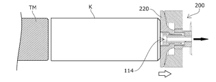
- the holding unit 111 of the transport turret 110 uses a first holding mechanism 200 as shown in FIGS.
- the first holding mechanism 200 has a negative pressure introducing member 210 that opens on the holding surface side through the gas flow hole 114, a contact member 220 that is movable with respect to the negative pressure introducing member 210, and a negative contact member 220.
- a coil spring 230 that is an urging member that urges the pressure introducing member 210 in the holding surface direction, and a guide member 240 that regulates the moving range of the contact member 220 in the suction direction are provided.
- the negative pressure introducing member 210 has a slide guide portion 211 that externally fits the slide sleeve 221 provided on the contact member 220 so that the slide sleeve 221 can advance and retreat, and a protrusion regulating step portion 212 is provided on the distal end side of the slide guide portion 211.
- a guide member 240 is fixed to the rear end side of the slide guide portion 211.
- the abutting member 220 is configured integrally with the sliding sleeve 221 so as to be able to advance and retreat along the slide guide portion 211, and in a protruding direction by a coil spring 230 that is an urging member provided between the abutting member 240 and the guide member 240. It is energized.
- An engagement step portion 222 that abuts on the protrusion regulating step portion 212 on the protruding side of the negative pressure introducing member 210 is provided on the distal end side of the sliding sleeve 221, and the engagement step portion 222 contacts the protrusion restriction step portion 212. Due to the contact, the movement range on the protruding side of the contact member 220 is restricted.
- a fitting restriction end 223 is formed on the fitting side of the abutting member 220, and the fitting regulating end 223 abuts on the fitting regulating surface 242 of the guide member 240, thereby moving the fitting side movement range of the abutting member 220. Is regulated. Further, on the outer peripheral side of the guide member 240, there is a deformation preventing portion 241 for preventing deformation of the outer edge portion when the contact member 220 is pressed. Note that the deformation preventing portion 241 of the first holding mechanism 200 may be provided as necessary, and may be unnecessary.
- the first holding mechanism 200 in a state where the can is not sucked and held, even if a negative pressure is introduced from the gas flow hole 114, only air is sucked from the open side of the negative pressure introduction member 210.
- the contact member 220 is urged in the protruding direction by the coil spring 230 and is located on the protruding side.
- the space between the abutting member 220 and the can bottom of the can K is closed, and the negative pressure from the gas circulation hole 114 is increased.
- the contact member 220 moves to the insertion side against the urging force of the coil spring 230 with the can K being sucked and held by the negative pressure.
- the impact at the moment of contact between the contact member 220 and the bottom of the can K can be mitigated by the movement against the urging force of the contact member 220.
- the holding unit 121 of the carry-out turret 120 uses a second holding mechanism 300 as shown in FIGS. Similar to the first holding mechanism 200, the second holding mechanism 300 includes a negative pressure introducing member 310 that opens on the holding surface side through the gas flow hole 124, and a contact member that is movable with respect to the negative pressure introducing member 310. 320, a coil spring 330 that is an urging member that urges the abutting member 320 against the negative pressure introducing member 310 in the holding surface direction, and a guide member 340 that regulates the moving range of the abutting member 320 in the suction direction. I have.
- the negative pressure introducing member 310 has a slide guide portion 311 that is fitted on the sliding cylinder portion 321 of the abutting member 320 so as to be able to advance and retreat, and a protrusion regulating step portion 312 is provided on the back side of the slide guide portion 311.
- a guide member 340 is fixed to the end side.
- the contact member 320 is biased in the protruding direction by a coil spring 330 that is a biasing member provided between the contact member 320 and the guide member 340.
- the contact member 320 is provided with an engagement step portion 322 that contacts the protrusion regulating step portion 312 of the negative pressure introducing member 310, and the engagement step portion 322 contacts the protrusion restriction step portion 312, thereby
- the movement range on the protruding side of the contact member 320 is restricted.
- a fitting restriction end 323 is formed on the fitting side of the contact member 320, and the fitting regulating end 323 comes into contact with the fitting restriction surface 342 of the guide member 340, thereby moving the fitting member 320 on the fitting side.
- the range is regulated.
- the negative pressure introducing member 310, the abutting member 320, and the guide member 340 are provided with air opening holes 313, 324, and 343 having diameters smaller than the gas flow holes 124 of the negative pressure introducing member 310, respectively, and external spaces are provided through these holes. Communicating with Further, the negative pressure introducing member 310 is formed to be smaller than the opening end (trim portion) of the can K as the object.
- the second holding mechanism 300 air is sucked from the open side of the negative pressure introducing member 310 even when negative pressure is introduced from the gas flow hole 124 in a state where the opening end of the can K is not sucked and held.
- the contact member 320 is urged in the protruding direction by the coil spring 330 and is positioned on the protruding side. In this state, when the opening end of the can K contacts the contact member 320, the space between the contact member 320 and the opening end of the can K is closed, and the negative pressure from the gas flow hole 124 increases. Due to this negative pressure, as shown in FIG.
- the contact member 320 moves to the insertion side against the urging force of the coil spring 330 with the opening end of the can K being sucked and held.
- the impact at the moment of contact between the contact member 320 and the opening end of the can K can be mitigated by movement against the urging force of the contact member 320.
- the negative pressure introduction member 310, the contact member 320, and the guide member 340 are provided with air release holes 313, 324, and 343, respectively, and the air is appropriately sucked so that the negative pressure in the can is suppressed to the target set value.
- the urging members of the first holding mechanism 200 and the second holding mechanism 300 described above are not limited to the coil springs 230 and 330, and other urging members can be used as long as they are elastic bodies.
- a transport operation of the can K in the transport device 100 configured as described above will be described.
- the can K is held by a holding mandrel TM arranged at a predetermined interval on the printing turret T in the previous process, and continuously transferred to the transport turret 110 by the rotation of the printing turret T. It moves toward the mounting position M1.
- the transport turret 110 is continuously rotated synchronously so that the holding surface of the holding unit 111 (first holding mechanism 200) and the can K held by the holding mandrel TM face each other at the transfer position M1.
- the transfer position M1 is set to an intermediate point on a straight line connecting the rotation centers C0 and C1 of the transport turret 110 and the printing turret T, the transfer position M1 is used for the holding unit 111 at the transfer position M1.
- the moving speed and direction of the first holding mechanism 200 and the holding mandrel TM are the same, and the intervals are also the same.
- the holding unit 111 that sucks and holds the can bottom of the can K by the negative pressure moves toward the rotation center C1 along the shape of the cam member 113 as the transport turret 110 rotates, and the moving speed is reduced and the adjacent holding unit 111 is held.
- interval with the unit 111 becomes narrow and it goes to the transfer position M2 of the can K to the carrying-out turret 120.
- Two unloading turrets 120 are provided, and the holding unit 121 (second holding mechanism 300) of the upstream unloading turret 120 is connected to every other holding unit 111 of the unloading turret 110 at the upstream transfer position M2.
- the holding unit 121 (second holding mechanism 300) of the downstream carry-out turret 120 is placed at every other holding unit 111 of the transport turret 110 at the downstream transfer position M2.
- the other half of the can K is received facing the (first holding mechanism 200).
- suction is performed through the gas flow holes 124 on the holding surface of the holding unit 121 of the carry-out turret 120, and positive pressure is applied to the gas flow holes 114 on the holding surface of the holding unit 111 of the transport turret 110 at the transfer position M2.
- the opening end of the can K is instantaneously sucked and held on the holding surface of the holding unit 121 at the transfer position M2.
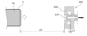
- the facing distance LM between the tip of the holding mandrel TM and the holding surface of the first holding mechanism 200 in a state in which the contact member 220 protrudes is substantially equal to the total length KL of the can K as shown in FIGS. Is set to As shown in FIG. 8, the can K is held by the holding mandrel TM with the bottom of the can facing the first holding mechanism 200 side, and the gas on the holding surface of the first holding mechanism 200 from before the transfer position M1.
- the suction is performed through the circulation hole 114, and the holding mandrel TM instantaneously releases the can K to the first holding mechanism 200 side by a known means at the transfer position M1.
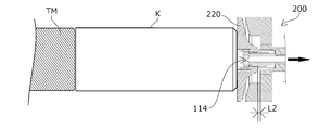
- the facing interval LM is set to be substantially equal to the total length KL of the can K, as shown in FIG. 9, the released can K has its bottom touching the contact member 220 of the first holding mechanism 200. When contacted, it is released from the holding mandrel TM. After the can bottom of the can K comes into contact with the contact member 220 of the first holding mechanism 200, as shown in FIG. 10, the first holding mechanism 200 is moved with the contact member 220 retracted by the movable distance L2. The can bottom of the can K is sucked and held by the used holding unit 111.
- the holding unit 111 that sucks and holds the can bottom of the can K by the negative pressure moves toward the rotation center C1 along the shape of the cam member 113 as the transport turret 110 rotates, and the moving speed is reduced and the adjacent holding unit 111 is held.
- interval with the unit 111 becomes narrow and it goes to the transfer position M2 of the can K to the carrying-out turret 120.
- Two unloading turrets 120 are provided, and the holding unit 121 of the upstream unloading turret 120 is opposed to every other holding unit 111 of the conveying turret 110 at the upstream transfer position M2, and half of the cans K are provided. And the holding unit 121 of the downstream carry-out turret 120 receives the remaining half of the cans K opposite to the other holding units 111 of the transport turret 110 at the downstream transfer position M2.
- the above-described second holding mechanism 300 is used for the holding unit 121 of the carry-out turret 120, and the first holding mechanism 200 used for the holding unit 111 of the transfer turret 110 and the carry-out turret 120 at the transfer position M2.
- An embodiment of the delivery method and delivery system according to the present invention is configured by the second holding mechanism 300 used in the holding unit 121.
- the abutting member 220 of the first holding mechanism 200 and the abutting member 320 of the second holding mechanism 300 are opposed to each other with a facing distance L1 in a protruding state, and the facing distance L1 is the total length of the can K to be delivered. It is smaller than or equal to KL.
- L1 + L2 when only the contact member 220 of the first holding mechanism 200 is retracted by the movable distance L2 is retracted by the movable distance L2
- L1 + L3 is set larger than the full length KL of the can K to be delivered.
- the can K is sucked and held by the first holding mechanism 200 with the opening end (trim portion) facing the second holding mechanism 300, and the second position from the front of the transfer position M ⁇ b> 2 Suction is started through the gas flow holes 124 on the holding surface of the holding mechanism 300.
- a clearance LK2 is provided between the opening end of the can K and the holding surface of the second holding mechanism 300, and positive pressure is applied to the gas flow holes 114 on the holding surface of the first holding mechanism 200.
- the can K is discharged to the holding surface side of the second holding mechanism 300.
- the abutting member 220 of the first holding mechanism 200 is also urged and protruded by the urging member 230 at the same time as the can K, so that the can bottom of the can K is open to the can K as shown in FIG.
- the second holding mechanism 300 After the opening end portion of the can K abuts on the abutting member 320 of the second holding mechanism 300, as shown in FIG. 14, the second holding mechanism 300 is in a state in which the abutting member 320 is retracted by the movable distance L3.
- the holding end 121 of the can K sucks and holds the opening end of the can K, and a clearance LK1 is generated between the can bottom of the can K and the holding surface of the first holding mechanism 200, thereby completing the delivery.
- each carry-out turret 120 receives every other can K at the transfer position M2. For this reason, the interval between the narrowed cans K is once doubled, but the holding unit 121 moves to the rotation center C2 side along the shape of the cam member 123 as the carry-out turret 120 rotates, and the moving speed is further reduced. In addition, the distance between adjacent holding units 121 becomes narrower again, and the can K is moved to the transfer position M3 on the conveyor 130.
- the conveyor 130 includes a conveyor belt 131 that has a plurality of gas flow holes 134 formed on the holding surface and can be sucked from the opposite side, and is configured to hold the cans K in two rows. In one row (the right column shown in FIG.
- the holding unit 121 of the upstream carry-out turret 120 is connected to the other row (the left column shown in FIG. 1).
- Cans K are transferred from 120 holding units 121. From the front of the transfer position M3, the bottom of the can K is sucked through the gas flow holes 134 on the holding surface of the conveyor belt 131 of the conveyor 130, and the gas on the holding surface of the holding unit 121 of the unloading turret 120 at the transfer position M3.
- the can bottom of the can K is instantaneously sucked and held on the holding surface of the conveyor belt 131 at the transfer position M3.
- the cans K are arranged in two rows, and at the same time, the interval between the cans K is narrowed and the moving speed is also reduced.
- the ratio of the radial positions of the transfer positions M1 and M2 in the transport turret 110 is 1/2 and the ratio of the radial positions of the transfer positions M2 and M3 in the two carry-out turrets 120 is 1/2
- the movement speed of the cans K is 1 ⁇ 4 of the movement speed of the cans K at the transfer position M1 of the printing turret T.
- the distance between the cans K is halved, and the cans K are divided into two rows by the carry-out conveyor 130. .
- the can K transferred from the carry-out turret 120 to the carry-out conveyor 130 is conveyed to the oven carry-in device 140 that is transferred to the oven D that performs the baking process.
- the oven D a large number of cans K arranged in a row in the width direction are baked while being conveyed in a direction perpendicular to the row of rows, and the cans K are transferred to the oven carry-in device 140 by the carry-out conveyor 130. Then, the oven carry-in device 140 transfers the two rows together to the oven D.
- the pitch of the rows of cans K is substantially the same as the pitch of the cans K in each row and that the cans K are arranged in a staggered manner with a half-pitch shift in adjacent rows.
- the transport path lengths of the two conveyor belts 131 of the carry-out conveyor 130 are different so that the cans K can reach the oven carry-in device 140 with a half-pitch deviation (so that the cans K can be discharged from the final end). It is configured as follows.
- the carry-out conveyor 130 has two side corner portions 132, and the curve radii of the two conveyor belts 131 in the side corner portions 132 are independent of each other. Therefore, the difference between the lengths of the respective transport paths can be freely changed. For this reason, the two conveyor belts in the side corner portion 132 are whatever the arrangement relationship of the two rows of cans K on the two conveyor belts 131 when they are delivered from the carry-out turret 120.
- the curved radii of 131 it can be designed so that the two rows of cans K can reliably reach the oven carry-in device 140 with a half-pitch deviation.
- a portion for providing a difference in the conveyance path length of the two conveyor belts 131 may be provided in any part.
- the two conveyor belts may be provided on the path of the carry-out conveyor 130.
- 131 may be provided with portions having different conveyance speeds to adjust the positional relationship between the cans K in each row.
- an interval adjusting mechanism in two stages of the transport turret 110 and the unloading turret 120, it is possible to achieve both the two-rows that are difficult to achieve in one stage and a reduction in the interval, and at the transfer position.
- the number of stages is further increased and the distance adjusting mechanism is increased in number, a plurality of lines of three or more can be formed, and the distance can be minimized.
- a turret that does not have an interval adjusting mechanism may be provided in any stage.
- the transfer device of the present invention can be used for any application and any transfer object as long as the transfer object continuously supplied at a predetermined interval from the previous process is carried out to the subsequent process by changing the interval and speed. It may be applicable to the conveyance of various objects to be conveyed. Further, the structure and delivery method for holding the object to be conveyed in each conveyance turret, unloading turret, and unloading conveyor may be any depending on the material and shape of the object to be conveyed. For example, when the object to be transported is a magnetic material such as a steel can, a holding mechanism using magnetic force may be used, and if the object to be transported is not easily deformed, a gripping mechanism or the like may be used. In addition, the holding mechanism and the delivery configuration of the above-described embodiment may be used for any use and any transported object as long as the transported object is transferred between different transport means. It can be applied to the conveyance and delivery of goods.
Landscapes
- Engineering & Computer Science (AREA)
- Mechanical Engineering (AREA)
- Specific Conveyance Elements (AREA)
Abstract
1列で搬入された被搬送物を複数列化しつつ、充分に間隔を狭めて低速化することが可能であり、構造や動作を単純化することができ、かつ、移載時の被搬送物の変形を防止するとともに、被搬送物の間隔の精度を向上することが可能な搬送装置を提供する。本発明は、被搬送物(K)を保持して搬送する搬送タレット(110)と、被搬送物(K)を保持して搬出コンベア(130)に受け渡す搬出タレット(120)とを有し、搬出コンベア(130)が被搬送物(K)を複数列で保持して搬出するように構成され、搬出タレット(120)が、搬出コンベア(130)の複数列にそれぞれ対応して複数設けられ、搬送タレット(110)と搬出タレット(120)は、保持された被搬送物(K)の半径位置を回転角度に応じて変化させる間隔調整機構を有する。
Description
本発明は、連続して供給される被搬送物を保持して搬送する搬送タレットと、被搬送物を保持して搬出コンベアに受け渡す搬出タレットと、被搬送物を保持して連続して搬出する搬出コンベアとを有する搬送装置に関する。
従来、前工程から所定の間隔で連続して供給される被搬送物を、間隔と速度を変更して後工程に搬出する搬送装置は公知である。
例えば、飲料などを充填する円筒状の缶の外周面に印刷・塗装する際、印刷工程で缶の外周面にインキにより印刷をした後、焼付工程でインキ、ワニスの硬化・定着を行う。
印刷工程では、缶を高速に所定の間隔で搬送しながら、外周面に印刷することが可能であるのに対し、焼付工程はある程度の時間を要することから、装置の長大化を防ぐため、狭い間隔で低速で搬送しながら行うのが望ましい。
このような要請から、連続して供給される被搬送物を保持して搬送するタレットと、被搬送物を保持して連続して搬出する搬出コンベアとを有し、前工程からタレットに搬入された缶を、搬送中に搬送速度と間隔を変更し、搬出コンベアで次工程に搬出する搬送装置が知られている(例えば、特許文献1、2等参照。)。
特許文献1、2で公知の搬送装置では、前工程(印刷工程)の搬出機構から缶が連続的に移載される搬送タレット(移送ホイール27、移載ホイール27)が、保持された缶の半径位置を回転角度に応じて変化させる間隔調整機構を有している。
搬送タレット(移送ホイール27、移載ホイール27)は、回転中に各缶の半径位置を小さくするとともに、缶を交互に異なる半径位置として2列にして次段に移載する。
特許文献1で公知の搬送装置では、次段がピン29により缶を保持して次工程に搬出する搬出コンベア(デコチェーン)であり、缶を2列にした状態で、搬送タレット(移送ホイール27、移載ホイール27)から搬出コンベア(デコチェーン)に移載して次工程に搬出するように構成されている。
搬送タレット(移送ホイール27、移載ホイール27)は、回転中に各缶の半径位置を小さくするとともに、缶を交互に異なる半径位置として2列にして次段に移載する。
特許文献1で公知の搬送装置では、次段がピン29により缶を保持して次工程に搬出する搬出コンベア(デコチェーン)であり、缶を2列にした状態で、搬送タレット(移送ホイール27、移載ホイール27)から搬出コンベア(デコチェーン)に移載して次工程に搬出するように構成されている。
特許文献2で公知の搬送装置では、搬送タレット(移載ホイール27)の次段には表面に缶を吸引保持する搬出タレット(コンベヤプレート102)が設けられており、缶を2列にした状態で、搬送タレット(移載ホイール27)から搬出タレット(コンベヤプレート102)に移載される。
搬出タレット(コンベヤプレート102)は、缶を2列に維持した状態で搬送し、2列のまま搬出コンベア(ベルトコンベヤ105)に移載し、搬出コンベア(ベルトコンベヤ105)は、表面に缶を吸引保持して次工程に搬出するように構成されている。
搬出タレット(コンベヤプレート102)は、缶を2列に維持した状態で搬送し、2列のまま搬出コンベア(ベルトコンベヤ105)に移載し、搬出コンベア(ベルトコンベヤ105)は、表面に缶を吸引保持して次工程に搬出するように構成されている。
これらの公知の搬送装置では、搬送タレット(移送ホイール27、移載ホイール27)が保持された缶の半径位置を回転角度に応じて変化させる間隔調整機構を有しており、この搬送タレットのみで間隔及び速度の変更と2列化を同時に行うため、間隔調整機構の構造や動作が複雑となり、充分に間隔を狭めて低速化することが困難であるという問題があった。
実際に、上記公知文献に記載された実施例では、2列の各列における缶の間隔は搬入時の1列の缶の間隔よりも大きくすることでこれらの問題の影響を少なくしている。
実際に、上記公知文献に記載された実施例では、2列の各列における缶の間隔は搬入時の1列の缶の間隔よりも大きくすることでこれらの問題の影響を少なくしている。
また、特許文献1で公知の搬送装置では、搬出コンベアはピンにより缶を保持することから、搬送タレットから搬出コンベアへの移載時に、十分低速になっていないと缶の円筒部の一箇所に大きな力や衝撃が加わって変形する虞があり、全体の高速化を阻害する要因となっていた。
特許文献2で公知の搬送装置では、搬送タレットで2列化された缶は、半径位置が異なるため接線速度も異なり、缶が移載される移載ホイールの各列も接線速度が異なるため、2列両方の缶の移載位置での速度を一致させることは不可能である。
また、両搬送タレットの中心を結ぶ線上の一点でのみ移動方向が一致し、その前後では缶の移動方向は必ず変化する。
そのため、移載位置での速度を一致させた列においても、移載の瞬間に缶の位置ズレが発生して正確な間隔とすることができず、また、肉薄の缶の場合、このズレの影響で保持面の端部が変形する虞もあり、やはり高速化を阻害する要因となっていた。
この問題は、移載ホイールから搬出コンベアへの移載時にも同様であった。
本発明は、前記した問題点を解決するものであり、1列で搬入された被搬送物を複数列化しつつ、充分に間隔を狭めて低速化することが可能であり、構造や動作を単純化することができ、かつ、移載時の被搬送物の変形を防止するとともに、被搬送物の間隔の精度を向上することが可能な搬送装置を提供することを目的とするものである。
本発明に係る搬送装置は、連続して供給される被搬送物を保持して搬送する搬送タレットと、被搬送物を保持して搬出コンベアに受け渡す搬出タレットと、被搬送物を保持して連続して搬出する搬出コンベアとを有する搬送装置であって、前記搬出コンベアが、被搬送物を複数列で保持して搬出するように構成され、前記搬出タレットが、前記搬出コンベアの複数列にそれぞれ対応して複数設けられ、前記搬送タレットと搬出タレットは、保持された被搬送物の半径位置を回転角度に応じて変化させる間隔調整機構を有することにより、前記課題を解決するものである。
本請求項1に係る搬送装置によれば、供給された被搬送物を受け取る搬送タレットと、被搬送物を搬出コンベアに受け渡す搬出タレットを有し、搬出タレットが搬出コンベアの複数列にそれぞれ対応して複数設けられていることで、前段の搬送タレットからの単列の被搬送物を、移載して複数列化することができる。
そして、搬送タレットと搬出タレットは、保持された被搬送物の半径位置を回転角度に応じて変化させる間隔調整機構を有することにより、これらの間隔調整機構はそれぞれ単列のまま、また、順次間隔及び速度を小さくすることができるため、充分に間隔を狭めて低速化することが可能であり、構造や動作を単純化することができる。
また、搬送タレットと搬出タレット間、あるいは搬出タレットと搬出コンベアの間の被搬送物の移載を全ての列で独立して行えるため、確実に同一速度、同一方向の位置で移載することが可能となり、移載時の被搬送物の変形を防止するとともに、被搬送物の間隔の精度を向上することができる。
そして、搬送タレットと搬出タレットは、保持された被搬送物の半径位置を回転角度に応じて変化させる間隔調整機構を有することにより、これらの間隔調整機構はそれぞれ単列のまま、また、順次間隔及び速度を小さくすることができるため、充分に間隔を狭めて低速化することが可能であり、構造や動作を単純化することができる。
また、搬送タレットと搬出タレット間、あるいは搬出タレットと搬出コンベアの間の被搬送物の移載を全ての列で独立して行えるため、確実に同一速度、同一方向の位置で移載することが可能となり、移載時の被搬送物の変形を防止するとともに、被搬送物の間隔の精度を向上することができる。
本請求項2に記載の構成によれば、搬送タレットと搬出タレットが、個々に被搬送物を保持する複数の保持ユニットを有し、間隔調整機構が、搬送タレットと搬出タレットに並べて固定的に設けられたカム部材と、カム部材と係合する保持ユニットに設けられたカムフォロア部材とを有することにより、搬送タレットと搬出タレットを回転させるだけで、保持された被搬送物の半径位置を回転角度に応じて変化させることができ、単純な構造とすることができる。
また、カム部材の形状を適宜設計することで、被搬送物を任意の軌道で移動させることができるため、設計の自由度が向上する。
本請求項3に記載の構成によれば、保持ユニットが、被搬送物の保持面に気体流通孔を有し、それぞれ個別に負圧で被搬送物を保持し、正圧で被搬送物を解放するように構成されていることにより、移載する搬送タレットと搬出タレット間あるいは搬出タレットと搬出コンベアの間を、被搬送物より僅かに大きな間隔で対向させることで、移載位置で瞬時に少ない衝撃で被搬送物を移載することができるため、移載時の被搬送物の変形を確実に防止するとともに、被搬送物の間隔の精度をさらに向上することができる。
また、カム部材の形状を適宜設計することで、被搬送物を任意の軌道で移動させることができるため、設計の自由度が向上する。
本請求項3に記載の構成によれば、保持ユニットが、被搬送物の保持面に気体流通孔を有し、それぞれ個別に負圧で被搬送物を保持し、正圧で被搬送物を解放するように構成されていることにより、移載する搬送タレットと搬出タレット間あるいは搬出タレットと搬出コンベアの間を、被搬送物より僅かに大きな間隔で対向させることで、移載位置で瞬時に少ない衝撃で被搬送物を移載することができるため、移載時の被搬送物の変形を確実に防止するとともに、被搬送物の間隔の精度をさらに向上することができる。
本請求項4に記載の構成によれば、保持ユニットが、被搬送物の移載位置の前後で直線移動軌跡を描くことにより、移載位置の前後で移動方向が変化することがない。
また、保持ユニットの直線移動軌跡を描く位置を、どちらも同じ半径位置となるように設定すれば、移動速度及び移動方向が被搬送物の移載位置の前後でも継続的に一致する。
このことで、移載タイミングが僅かに変化した場合でも被加工物の位置ズレを防止でき、移載時の被搬送物の変形を確実に防止するとともに、被搬送物の間隔の精度をさらに向上することができる。
本請求項5に記載の構成によれば、搬出コンベアは、隣り合う列の被搬送物が半ピッチずれた状態で最終端部から排出可能に構成されていることにより、隣り合う列の被搬送物の最小間隔を最も大きくすることができる。
このことで、隣り合う列の間隔を小さくして、スペース効率を向上させることが可能となるとともに、搬送時あるいは後工程において、被搬送物の位置がずれたり移動した場合でも、被搬送物同士の接触や干渉を抑制することが可能となる。
本請求項6に記載の構成によれば、搬出コンベアが、複数列でそれぞれ独立して異なる搬送経路長を有していることにより、被搬送物の配置関係に関わらず、確実に被搬送物を半ピッチずれた状態で到達させるように設計することが可能となる。
本請求項7に記載の構成によれば、負圧導入部材に対して移動可能な当接部材と、当接部材を負圧導入部材に対して保持面方向に付勢する付勢部材と、当接部材の吸引方向の移動範囲を規制するガイド部材とを備えていることで、第1保持機構及び第2保持機構が対象物を吸着して受け渡す際に、対象物がまず当接部材に当接した後に、付勢部材による押圧力に抗して当接部材が移動し、当接部材がガイド部材に規制されて停止した状態で吸着保持されるため、対象物が吸着される際の衝撃が付勢部材に押圧された当接部材の動きによって緩和され、対象物の変形や損傷を防止することができる。
また、対象物と当接部材とが当接した時点で吸着保持位置が確定するため、保持位置のズレを低減することができる。
そして、対象物の変形を防止し、保持位置のズレを低減しつつ、吸着保持動作の高速化を図ることが可能となる。
本請求項8に記載の構成によれば、第2保持機構が、対象物を保持した際に対象物内から外部に連通する大気開放孔を有することによりエアを適宜吸入し、対象物内の負圧を目標設定値に抑え、また、対象物の開口端部を吸着保持する際のエアの吸引(高バキューム)をバランス良く短時間で行うことができる。
このことで、例えば、対象物が非常に変形しやすい開口端部を有する缶等であっても、開口端部の変形を防止し、保持位置のズレを低減しつつ、吸着保持動作の高速化を図ることが可能となる。
本請求項9に記載の構成によれば、受け渡しの際に、対象物が2つの保持機構の当接部材のいずれか、あるいは両方に常に当接した状態を維持することが可能となるため、対象物が2つの保持機構の当接部材のいずれにも当接しない時に発生する2つの保持機構の速度ベクトルの差や重力加速度、空気抵抗等による影響が低減され、保持位置のズレがなく、受け渡し動作の高速化を図ることが可能となる。
100 ・・・ 搬送装置
110 ・・・ 搬送タレット
111 ・・・ 保持ユニット
112 ・・・ カムフォロア部材
113 ・・・ カム部材
114 ・・・ 気体流通孔
120 ・・・ 搬出タレット
121 ・・・ 保持ユニット
122 ・・・ カムフォロア部材
123 ・・・ カム部材
124 ・・・ 気体流通孔
130 ・・・ 搬出コンベア
131 ・・・ コンベアベルト
132 ・・・ 側方コーナー部
134 ・・・ 気体流通孔
140 ・・・ オーブン搬入装置
200 ・・・ 第1保持機構(吸着保持機構)
210 ・・・ 負圧導入部材
211 ・・・ スライド案内部
212 ・・・ 突出規制段部
220 ・・・ 当接部材
221 ・・・ 摺動スリーブ
222 ・・・ 係合段部
223 ・・・ 嵌入規制端部
230 ・・・ コイルばね(付勢部材)
240 ・・・ ガイド部材
241 ・・・ 変形防止部
242 ・・・ 嵌入規制面
300 ・・・ 第2保持機構(吸着保持機構)
310 ・・・ 負圧導入部材
311 ・・・ スライド案内部
312 ・・・ 突出規制段部
313 ・・・ 大気開放孔
320 ・・・ 当接部材
321 ・・・ 摺動筒部
322 ・・・ 係合段部
323 ・・・ 嵌入規制端部
324 ・・・ 大気開放孔
330 ・・・ コイルばね(付勢部材)
340 ・・・ ガイド部材
342 ・・・ 嵌入規制面
343 ・・・ 大気開放孔
K ・・・ 缶(被搬送物)
T ・・・ 印刷タレット
TM ・・・ 保持マンドレル
S ・・・ 直線移動軌跡領域
M ・・・ 移載位置
C ・・・ 回転中心
D ・・・ オーブン
L1 ・・・ 対向間隔(第1保持機構と第2保持機構の双方突出時)
L2 ・・・ 移動可能距離(第1保持機構の)
L3 ・・・ 移動可能距離(第2保持機構の)
LM ・・・ 対向間隔(保持マンドレルと第1保持機構の)
LK1 ・・ クリアランス(缶と第1保持機構の)
LK2 ・・ クリアランス(缶と第2保持機構の)
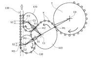
本発明の一実施形態に係る搬送装置100は、図1乃至図3に示すように、印刷工程から焼付工程まで被搬送物である缶Kを搬送するものであり、搬送タレット110が、被搬送物である缶Kを印刷タレットTから受け取り、搬出コンベア130が、被搬送物である缶Kを2列で保持してオーブンDに搬出するように構成されている。
タレットとして、印刷タレットTから供給された缶Kを受け取る搬送タレット110と、缶Kを搬出コンベア130に受け渡す搬出タレット120とを有している。
搬出タレット120は、搬出コンベア130の2列にそれぞれ対応して2つ設けられている。
搬送タレット110及び2つの搬出タレット120は、それぞれ、個々に缶Kを吸着して保持する複数の保持ユニット111、121を有している。
タレットとして、印刷タレットTから供給された缶Kを受け取る搬送タレット110と、缶Kを搬出コンベア130に受け渡す搬出タレット120とを有している。
搬出タレット120は、搬出コンベア130の2列にそれぞれ対応して2つ設けられている。
搬送タレット110及び2つの搬出タレット120は、それぞれ、個々に缶Kを吸着して保持する複数の保持ユニット111、121を有している。
保持ユニット111、121は、搬送タレット110及び2つの搬出タレット120上で半径方向に移動可能に配置され、間隔調整機構によって保持された缶Kの半径位置を回転角度に応じて変化させるように構成されている。
間隔調整機構は、搬送タレット110及び2つの搬出タレット120に固定的に設けられたカム部材113、123と、カム部材113、123と係合して保持ユニット111、121に設けられたカムフォロア部材112、122とで構成されている。
また、保持ユニット111、121の缶Kの保持面には、気体流通孔114、124が設けられ、それぞれ個別に気体流通孔114、124を通じて供給される負圧で缶Kを保持し、正圧で缶Kを解放するように構成されている。
なお、気体流通孔114、124を通じて供給される負圧及び正圧は、図示しない公知の手段で、それぞれ、搬送タレット110及び2つの搬出タレット120の回転と同期して缶Kの保持、移載のタイミングで瞬時に動作可能に構成されている。
図1に示すように、印刷タレットTの缶を保持する保持マンドレルTMから搬送タレット110への缶Kの移載位置M1は、それぞれの回転中心C0とC1を結んだ直線上にあり、搬送タレット110から2つの搬出タレット120への缶Kの移載位置M2は、それぞれの回転中心C1とC2を結んだ直線上にある。
また、2つの搬出タレット120から搬出コンベア130への缶Kの移載位置M3は、搬出タレット120の回転中心C2から搬出コンベア130の搬送方向に垂直となるように延ばした直線上にある。
保持ユニット111、121のそれぞれの移動軌跡は、搬送タレット110から2つの搬出タレット120への缶Kの移載位置M2の前後において、回転中心C1とC2を結んだ直線上の中間点で直交する直線移動軌跡領域S1がそれぞれ形成されるように構成されている。
また、保持ユニット121の移動軌跡は、搬出タレット120から搬出コンベア130への缶Kの移載位置M3の前後において、搬出コンベア130の搬送方向に延びる直線移動軌跡領域S2がそれぞれ形成されるように構成されている。
搬出コンベア130は、2つの搬出タレット120から缶Kが受け渡される2列のコンベアベルト131を有しており、図3に示すように、オーブンDに移載するオーブン搬入装置140まで、缶Kを2列で搬送するように構成されている。
搬送タレット110の保持ユニット111は、図4、図5に示すような第1保持機構200が用いられる。
第1保持機構200は、気体流通孔114を介して保持面側を開口した負圧導入部材210と、負圧導入部材210に対して移動可能な当接部材220と、当接部材220を負圧導入部材210に対して保持面方向に付勢する付勢部材であるコイルばね230と、当接部材220の吸引方向の移動範囲を規制するガイド部材240を備えている。
負圧導入部材210は、当接部材220に設けられた摺動スリーブ221を進退可能に外嵌するスライド案内部211を有し、スライド案内部211の先端側には突出規制段部212が設けられ、スライド案内部211の後端側にはガイド部材240が固定されている。
第1保持機構200は、気体流通孔114を介して保持面側を開口した負圧導入部材210と、負圧導入部材210に対して移動可能な当接部材220と、当接部材220を負圧導入部材210に対して保持面方向に付勢する付勢部材であるコイルばね230と、当接部材220の吸引方向の移動範囲を規制するガイド部材240を備えている。
負圧導入部材210は、当接部材220に設けられた摺動スリーブ221を進退可能に外嵌するスライド案内部211を有し、スライド案内部211の先端側には突出規制段部212が設けられ、スライド案内部211の後端側にはガイド部材240が固定されている。
当接部材220は、摺動スリーブ221と一体となってスライド案内部211に沿って進退可能に構成され、ガイド部材240との間に設けられた付勢部材であるコイルばね230によって突出方向に付勢されている。
摺動スリーブ221の先端側には負圧導入部材210の突出側の突出規制段部212と当接する係合段部222が設けられており、係合段部222が突出規制段部212に当接することにより、当接部材220の突出側の移動範囲が規制されている。
当接部材220の嵌入側には嵌入規制端部223が形成されており、嵌入規制端部223がガイド部材240の嵌入規制面242に当接することにより、当接部材220の嵌入側の移動範囲が規制されている。
また、ガイド部材240の外周側には、当接部材220が押圧された際の外縁部の変形を防止する変形防止部241を有している。
なお、この第1保持機構200の変形防止部241は、必要に応じて設ければ良く、不要とすることもできる。
この第1保持機構200によれば、缶を吸着保持していない状態では、気体流通孔114から負圧を導入しても負圧導入部材210の開放側からエアーを吸引するのみで、図4に示すように、当接部材220は、コイルばね230によって突出方向に付勢され突出側に位置している。
この状態で、缶Kの缶底(ボトム部)が当接部材220に当接すると、当接部材220と缶Kの缶底との空間が閉塞されて気体流通孔114からの負圧が大きくなり、この負圧によって、図5に示すように、当接部材220は缶Kを吸着保持した状態でコイルばね230の付勢力に抗して嵌入側に移動する。
このことで、当接部材220と缶Kの缶底との当接の瞬間の衝撃を、当接部材220の付勢力に抗した移動により緩和することができる。
この状態で、缶Kの缶底(ボトム部)が当接部材220に当接すると、当接部材220と缶Kの缶底との空間が閉塞されて気体流通孔114からの負圧が大きくなり、この負圧によって、図5に示すように、当接部材220は缶Kを吸着保持した状態でコイルばね230の付勢力に抗して嵌入側に移動する。
このことで、当接部材220と缶Kの缶底との当接の瞬間の衝撃を、当接部材220の付勢力に抗した移動により緩和することができる。
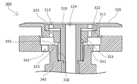
搬出タレット120の保持ユニット121は、図6、図7に示すような第2保持機構300が用いられる。
第2保持機構300は、第1保持機構200と同様に、気体流通孔124を介して保持面側を開口した負圧導入部材310と、負圧導入部材310に対して移動可能な当接部材320と、当接部材320を負圧導入部材310に対して保持面方向に付勢する付勢部材であるコイルばね330と、当接部材320の吸引方向の移動範囲を規制するガイド部材340を備えている。
負圧導入部材310は、当接部材320の摺動筒部321を進退可能に外嵌するスライド案内部311を有し、その裏側に突出規制段部312が設けられ、スライド案内部311の後端側にはガイド部材340が固定されている。
第2保持機構300は、第1保持機構200と同様に、気体流通孔124を介して保持面側を開口した負圧導入部材310と、負圧導入部材310に対して移動可能な当接部材320と、当接部材320を負圧導入部材310に対して保持面方向に付勢する付勢部材であるコイルばね330と、当接部材320の吸引方向の移動範囲を規制するガイド部材340を備えている。
負圧導入部材310は、当接部材320の摺動筒部321を進退可能に外嵌するスライド案内部311を有し、その裏側に突出規制段部312が設けられ、スライド案内部311の後端側にはガイド部材340が固定されている。
当接部材320は、ガイド部材340との間に設けられた付勢部材であるコイルばね330によって突出方向に付勢されている。
当接部材320には、負圧導入部材310の突出規制段部312と当接する係合段部322が設けられており、係合段部322が突出規制段部312に当接することにより、当接部材320の突出側の移動範囲が規制されている。
当接部材320の嵌入側には、嵌入規制端部323が形成されており、嵌入規制端部323がガイド部材340の嵌入規制面342に当接することにより、当接部材320の嵌入側の移動範囲が規制されている。
当接部材320には、負圧導入部材310の突出規制段部312と当接する係合段部322が設けられており、係合段部322が突出規制段部312に当接することにより、当接部材320の突出側の移動範囲が規制されている。
当接部材320の嵌入側には、嵌入規制端部323が形成されており、嵌入規制端部323がガイド部材340の嵌入規制面342に当接することにより、当接部材320の嵌入側の移動範囲が規制されている。
負圧導入部材310、当接部材320、及びガイド部材340には、負圧導入部材310の気体流通孔124より小径の大気開放孔313、324、343がそれぞれ設けられ、これらを介して外部空間に連通している。
また、負圧導入部材310は、対象物である缶Kの開口端部(トリム部)より小さく形成されている。
また、負圧導入部材310は、対象物である缶Kの開口端部(トリム部)より小さく形成されている。
この第2保持機構300によれば、缶Kの開口端部を吸着保持していない状態では、気体流通孔124から負圧を導入しても負圧導入部材310の開放側からエアーを吸引するのみで、図6に示すように、当接部材320は、コイルばね330によって突出方向に付勢され突出側に位置している。
この状態で、缶Kの開口端部が当接部材320に当接すると、当接部材320と缶Kの開口端部との空間が閉塞されて気体流通孔124からの負圧が大きくなり、この負圧によって、図7に示すように、当接部材320は缶Kの開口端部を吸着保持した状態で、コイルばね330の付勢力に抗して嵌入側に移動する。
このことで、当接部材320と缶Kの開口端部との当接の瞬間の衝撃を、当接部材320の付勢力に抗した移動により緩和することができる。
さらに、負圧導入部材310、当接部材320、及びガイド部材340に、それぞれ大気開放孔313、324、343を設けてエアーを適宜吸入することにより、缶内の負圧を目標設定値に抑え、また、缶Kの開口端部を吸着保持する際のエアーの吸引(高バキューム)をバランス良く短時間で行い、強度が弱い缶Kの開口端部を吸着しても、その変形を防止することができる。
なお、前述した第1保持機構200、第2保持機構300の付勢部材はコイルばね230、330に限定されず、弾性体であれば他の付勢部材を用いることができる。
以上のように構成された搬送装置100における缶Kの搬送動作について説明する。
缶Kは、図1、図2に示すように、前工程の印刷タレットTに所定の間隔で配置された保持マンドレルTMに保持され、印刷タレットTの回転によって連続的に搬送タレット110への移載位置M1に向けて移動する。
搬送タレット110は、保持ユニット111(第1保持機構200)の保持面と保持マンドレルTMに保持された缶Kとが移載位置M1で対向するように、同期して連続回転している。
この時、移載位置M1が搬送タレット110と印刷タレットTのそれぞれの回転中心C0とC1を結んだ直線上の中間点に設定されているため、移載位置M1では、保持ユニット111に用いられる第1保持機構200と保持マンドレルTMの移動速度及び方向が同一となり、その間隔も同じである。
そして、移載位置M1の手前から、保持ユニット111の保持面の気体流通孔114を通じて吸引し、移載位置M1において保持マンドレルTMが缶Kの保持を開放することで、缶Kの缶底が、移載位置M1で瞬時に保持ユニット111の保持面に吸引保持される。
缶Kの缶底を負圧により吸引保持した保持ユニット111は、搬送タレット110の回転に伴いカム部材113の形状に沿って回転中心C1側に移動し、移動速度が減速されるとともに隣接する保持ユニット111との間隔が狭くなって、搬出タレット120への缶Kの移載位置M2に向かう。
搬出タレット120は2つ設けられており、上流側の搬出タレット120の保持ユニット121(第2保持機構300)は、上流側の移載位置M2において搬送タレット110の1つおきの保持ユニット111と対向して缶Kの半数を受け取り、下流側の搬出タレット120の保持ユニット121(第2保持機構300)は、下流側の移載位置M2において搬送タレット110の残りの1つおきの保持ユニット111(第1保持機構200)と対向して缶Kの残りの半数を受け取る。
移載位置M2の手前から、搬出タレット120の保持ユニット121の保持面の気体流通孔124を通じて吸引し、移載位置M2において搬送タレット110の保持ユニット111の保持面の気体流通孔114に正圧を与えて缶Kの缶底の保持を開放することで、缶Kの開口端部が、移載位置M2で瞬時に保持ユニット121の保持面に吸引保持される。
保持マンドレルTMの先端と、当接部材220が突出した状態の第1保持機構200の保持面との対向間隔LMは、図8乃至図10に示すように、缶Kの全長KLとほぼ等しくなるように設定されている。
缶Kは、図8に示すように、缶底を第1保持機構200側に向けて保持マンドレルTMに保持されており、移載位置M1の手前から、第1保持機構200の保持面の気体流通孔114を通じて吸引し、移載位置M1において保持マンドレルTMが缶Kを公知の手段で第1保持機構200側に瞬時に放出する。
対向間隔LMが缶Kの全長KLとほぼ等しくなるように設定されているため、図9に示すように、放出された缶Kは、缶底が第1保持機構200の当接部材220に当接した際に保持マンドレルTMから開放される。
缶Kの缶底が第1保持機構200の当接部材220に当接した後、図10に示すように、当接部材220が移動可能距離L2だけ後退した状態で、第1保持機構200を用いた保持ユニット111により缶Kの缶底が吸引保持される。
缶Kの缶底を負圧により吸引保持した保持ユニット111は、搬送タレット110の回転に伴いカム部材113の形状に沿って回転中心C1側に移動し、移動速度が減速されるとともに隣接する保持ユニット111との間隔が狭くなって、搬出タレット120への缶Kの移載位置M2に向かう。
搬出タレット120は2つ設けられており、上流側の搬出タレット120の保持ユニット121は、上流側の移載位置M2において搬送タレット110の1つおきの保持ユニット111と対向して缶Kの半数を受け取り、下流側の搬出タレット120の保持ユニット121は、下流側の移載位置M2において搬送タレット110の残りの1つおきの保持ユニット111と対向して缶Kの残りの半数を受け取る。
搬出タレット120は2つ設けられており、上流側の搬出タレット120の保持ユニット121は、上流側の移載位置M2において搬送タレット110の1つおきの保持ユニット111と対向して缶Kの半数を受け取り、下流側の搬出タレット120の保持ユニット121は、下流側の移載位置M2において搬送タレット110の残りの1つおきの保持ユニット111と対向して缶Kの残りの半数を受け取る。
搬出タレット120の保持ユニット121には、前述の第2保持機構300が用いられており、移載位置M2において、搬送タレット110の保持ユニット111に用いられた第1保持機構200と、搬出タレット120の保持ユニット121に用いられた第2保持機構300で、本発明に係る受け渡し方法、及び、受け渡しシステムの一実施形態が構成される。
第1保持機構200の当接部材220と第2保持機構300の当接部材320は、両方とも突出した状態で対向間隔L1で対向しており、対向間隔L1は、受け渡される缶Kの全長KLよりも小さく、または同じに設定されている。
また、第1保持機構200の当接部材220のみが移動可能距離L2だけ後退した際の間隔L1+L2、及び、第2保持機構300の当接部材320のみが移動可能距離L3だけ後退した際の間隔L1+L3は、それぞれ、受け渡される缶Kの全長KLよりも大きく設定されている。
第1保持機構200の当接部材220と第2保持機構300の当接部材320は、両方とも突出した状態で対向間隔L1で対向しており、対向間隔L1は、受け渡される缶Kの全長KLよりも小さく、または同じに設定されている。
また、第1保持機構200の当接部材220のみが移動可能距離L2だけ後退した際の間隔L1+L2、及び、第2保持機構300の当接部材320のみが移動可能距離L3だけ後退した際の間隔L1+L3は、それぞれ、受け渡される缶Kの全長KLよりも大きく設定されている。
缶Kは、図12に示すように、開口端部(トリム部)を第2保持機構300側に向けて第1保持機構200に吸引保持されており、移載位置M2の手前から、第2保持機構300の保持面の気体流通孔124を通じて吸引を開始する。
移載位置M2において、缶Kの開口端部と第2保持機構300の保持面との間はクリアランスLK2を有しており、第1保持機構200の保持面の気体流通孔114に正圧を与えて缶Kを第2保持機構300の保持面側に放出する。
この時、缶Kと同時に第1保持機構200の当接部材220も付勢部材230に付勢されて突出することで、図13に示すように、缶Kの缶底は、缶Kの開口端部が第2保持機構300の当接部材320に当接するまで、第1保持機構200の当接部材220に対する当接を継続することで、2つの保持機構の速度ベクトルの差や重力加速度、空気抵抗等による影響が低減され、保持位置のズレがなく、受け渡し動作の高速化を図ることが可能となる。
缶Kの開口端部が第2保持機構300の当接部材320に当接した後、図14に示すように、当接部材320が移動可能距離L3だけ後退した状態で、第2保持機構300を用いた保持ユニット121により缶Kの開口端部が吸引保持され、缶Kの缶底と第1保持機構200の保持面との間はクリアランスLK1が生じて受け渡しが完了する。
この受け渡しによって、それぞれの搬出タレット120は、移載位置M2において1缶おきの缶Kを受け取る。
このため、狭くなった缶Kの間隔が一旦倍になるが、保持ユニット121は搬出タレット120の回転に伴いカム部材123の形状に沿って回転中心C2側に移動し、移動速度がさらに減速されるとともに隣接する保持ユニット121との再び間隔が狭くなって、搬送コンベア130への缶Kの移載位置M3に向かう。
搬送コンベア130は、例えば、保持面に多数の気体流通孔134を形成し、反対側から吸引可能なコンベアベルト131から成り、缶Kを2列で保持可能に構成されている。そして、一方の列(図1に図示する右側の列)には、上流側の搬出タレット120の保持ユニット121から、他方の列(図1に図示する左側の列)には下流側の搬出タレット120の保持ユニット121から、それぞれ缶Kが移載される。
移載位置M3の手前から、搬送コンベア130のコンベアベルト131の保持面の気体流通孔134を通じて缶Kの缶底を吸引し、移載位置M3において搬出タレット120の保持ユニット121の保持面の気体流通孔124に正圧を与えて缶Kの開口端部の保持を開放することで、缶Kの缶底が移載位置M3で瞬時にコンベアベルト131の保持面に吸引保持される。
このような印刷タレットTから搬出コンベア130に至る一連の動作により、缶Kを2列化すると同時に、缶Kの間隔が狭くなり、移動速度も減速される。
例えば、搬送タレット110における移載位置M1とM2の半径位置の比が1/2、2つの搬出タレット120における移載位置M2とM3の半径位置の比が1/2とすると、搬出コンベア130における缶Kの移動速度は、印刷タレットTの移載位置M1での缶Kの移動速度の1/4、同様に缶Kの間隔は1/2となり、かつ、搬出コンベア130で2列化される。
例えば、搬送タレット110における移載位置M1とM2の半径位置の比が1/2、2つの搬出タレット120における移載位置M2とM3の半径位置の比が1/2とすると、搬出コンベア130における缶Kの移動速度は、印刷タレットTの移載位置M1での缶Kの移動速度の1/4、同様に缶Kの間隔は1/2となり、かつ、搬出コンベア130で2列化される。
搬出タレット120から搬出コンベア130に受け渡された缶Kは、焼付工程を行うオーブンDに移載するオーブン搬入装置140まで搬送される。
オーブンDでは、幅方向に1列に並べられた多数の缶Kを、列の並びと直交する方向に搬送しながら焼付を行うものであり、缶Kは、搬出コンベア130でオーブン搬入装置140に運び込まれ、オーブン搬入装置140が2列をまとめてオーブンDに移載する。
オーブンDでは、缶Kの列のピッチと、各列の缶Kのピッチをほぼ同一とし、かつ、隣り合う列で缶Kが半ピッチずれて千鳥状に配列されるのが望ましいため、2列の缶Kがちょうど半ピッチずれた状態でオーブン搬入装置140に到達するように(最終端部から缶Kを排出可能なように)、搬出コンベア130の2つのコンベアベルト131の搬送経路長が異なるように構成されている。
オーブンDでは、幅方向に1列に並べられた多数の缶Kを、列の並びと直交する方向に搬送しながら焼付を行うものであり、缶Kは、搬出コンベア130でオーブン搬入装置140に運び込まれ、オーブン搬入装置140が2列をまとめてオーブンDに移載する。
オーブンDでは、缶Kの列のピッチと、各列の缶Kのピッチをほぼ同一とし、かつ、隣り合う列で缶Kが半ピッチずれて千鳥状に配列されるのが望ましいため、2列の缶Kがちょうど半ピッチずれた状態でオーブン搬入装置140に到達するように(最終端部から缶Kを排出可能なように)、搬出コンベア130の2つのコンベアベルト131の搬送経路長が異なるように構成されている。
本実施形態では、図3に示すように、搬出コンベア130は、2箇所の側方コーナー部132を有しており、この側方コーナー部132における2つのコンベアベルト131の曲線半径をそれぞれ独立して設定することで、それぞれの搬送経路長の差を自由に変更できる。
このため、搬出タレット120から受け渡された時点での2つのコンベアベルト131上での2列の缶Kの配置関係がどのようなものであっても、側方コーナー部132における2つのコンベアベルト131の曲線半径をそれぞれ適宜設定することで、確実に2列の缶Kがちょうど半ピッチずれた状態でオーブン搬入装置140に到達するように設計することができる。
なお、搬出コンベア130の全体の配置・経路に応じて、2つのコンベアベルト131の搬送経路長の差を設ける部分をいかなる部分に設けてもよく、搬出コンベア130の経路上に、2つのコンベアベルト131で搬送速度の異なる部分を設けて、それぞれの列の缶Kの位置関係を調整するようにしてもよい。
本実施形態では、搬送タレット110と搬出タレット120の2段階で間隔調整機構を有することで、1段では達成することが困難な2列化と間隔の減少を両立させ、かつ、移載位置での速度差をなくしているが、さらに多段とし、間隔調整機構を多段化することで、3列以上の複数列化も可能であり、間隔も最小化することが可能となる。
また、多段とする際には、いずれかの段に間隔調整機構を有さないタレットを設けてもよい。
また、多段とする際には、いずれかの段に間隔調整機構を有さないタレットを設けてもよい。
本発明の搬送装置は、前工程から所定の間隔で連続して供給される被搬送物を、間隔と速度を変更して後工程に搬出するものであれば、いかなる用途、いかなる被搬送物であってもよく、様々な被搬送物の搬送に適用可能である。
また、各搬送タレット、搬出タレット、搬出コンベアにおける被搬送物の保持のための構成や受け渡し方法は、被搬送物の材質、形状に応じていかなるものであってもよい。
例えば、被搬送物がスチール缶等の磁性体の場合、磁力による保持機構であってもよく、被搬送物が変形しにくいものであれば、把持機構等によるものであってもよい。
また、前述の実施形態の保持機構やその受け渡しの構成は、被搬送物を異なる搬送手段の間で受け渡すものであれば、いかなる用途、いかなる被搬送物であってもよく、様々な被搬送物の吸着搬送、受け渡しに適用可能である。
また、各搬送タレット、搬出タレット、搬出コンベアにおける被搬送物の保持のための構成や受け渡し方法は、被搬送物の材質、形状に応じていかなるものであってもよい。
例えば、被搬送物がスチール缶等の磁性体の場合、磁力による保持機構であってもよく、被搬送物が変形しにくいものであれば、把持機構等によるものであってもよい。
また、前述の実施形態の保持機構やその受け渡しの構成は、被搬送物を異なる搬送手段の間で受け渡すものであれば、いかなる用途、いかなる被搬送物であってもよく、様々な被搬送物の吸着搬送、受け渡しに適用可能である。
Claims (9)
- 連続して供給される被搬送物を保持して搬送する搬送タレットと、被搬送物を保持して搬出コンベアに受け渡す搬出タレットと、被搬送物を保持して連続して搬出する搬出コンベアとを有する搬送装置であって、
前記搬出コンベアが、被搬送物を複数列で保持して搬出するように構成され、
前記搬出タレットが、前記搬出コンベアの複数列にそれぞれ対応して複数設けられ、
前記搬送タレットと搬出タレットは、保持された被搬送物の半径位置を、回転角度に応じて変化させる間隔調整機構を有することを特徴とする搬送装置。 - 前記搬送タレットと搬出タレットが、個々に被搬送物を保持する複数の保持ユニットを有し、
前記間隔調整機構が、前記タレットに並べて固定的に設けられたカム部材と、前記カム部材と係合する前記保持ユニットに設けられたカムフォロア部材とを有することを特徴とする請求項1に記載の搬送装置。 - 前記保持ユニットが、被搬送物の保持面に気体流通孔を有し、
前記保持ユニットが、それぞれ個別に負圧で被搬送物を保持し、正圧で被搬送物を解放するように構成されていることを特徴とする請求項2に記載の搬送装置。 - 前記保持ユニットが、被搬送物の移載位置の前後で直線移動軌跡を描くことを特徴とする請求項2又は3に記載の搬送装置。
- 前記搬出コンベアは、隣り合う列の被搬送物が半ピッチずれた状態で最終端部から排出可能に構成されていることを特徴とする請求項1乃至4のいずれかに記載の搬送装置。
- 前記搬出コンベアが、複数列でそれぞれ独立して異なる搬送経路長を有していることを特徴とする請求項1乃至5のいずれかに記載の搬送装置。
- 前記搬送タレットと搬出タレットの一方が対象物の底部を吸着する第1保持機構、他方が対象物の開口端部を吸着する第2保持機構を有し、
前記第1保持機構及び第2保持機構がいずれも負圧導入部材と、前記負圧導入部材に対して移動可能な当接部材と、前記当接部材を前記負圧導入部材に対して保持面方向に付勢する付勢部材と、前記当接部材の吸引方向の移動範囲を規制するガイド部材とを備え、
前記負圧導入部材が、気体流通孔を介して保持面側に開口していること特徴とする請求項1乃至6のいずれかに記載の搬送装置。 - 前記第2保持機構が、対象物を保持した際に対象物内から外部に連通する大気開放孔を有することを特徴とする請求項7に記載の搬送装置。
- 対向位置で対向する前記第1保持機構及び第2保持機構は、それぞれの当接部材の保持面の対向間隔が、両方の当接部材とも突出した状態で対象物より短く、または同じで、両方の当接部材が吸引方向に移動した状態で対象物より長くなるように配置されていることを特徴とする請求項7又は請求項8に記載の搬送装置。
Priority Applications (2)
| Application Number | Priority Date | Filing Date | Title |
|---|---|---|---|
| EP15847694.5A EP3202692A4 (en) | 2014-09-30 | 2015-09-09 | Conveyance device |
| US15/471,389 US10272668B2 (en) | 2014-09-30 | 2017-03-28 | Conveyance device |
Applications Claiming Priority (6)
| Application Number | Priority Date | Filing Date | Title |
|---|---|---|---|
| JP2014200062 | 2014-09-30 | ||
| JP2014-200062 | 2014-09-30 | ||
| JP2015094279A JP5975238B2 (ja) | 2014-09-30 | 2015-05-01 | 搬送装置 |
| JP2015-094279 | 2015-05-01 | ||
| JP2015-094280 | 2015-05-01 | ||
| JP2015094280A JP5988064B1 (ja) | 2015-05-01 | 2015-05-01 | 受け渡し保持機構、受け渡し方法及び受け渡しシステム |
Related Child Applications (1)
| Application Number | Title | Priority Date | Filing Date |
|---|---|---|---|
| US15/471,389 Continuation US10272668B2 (en) | 2014-09-30 | 2017-03-28 | Conveyance device |
Publications (1)
| Publication Number | Publication Date |
|---|---|
| WO2016052104A1 true WO2016052104A1 (ja) | 2016-04-07 |
Family
ID=55630147
Family Applications (1)
| Application Number | Title | Priority Date | Filing Date |
|---|---|---|---|
| PCT/JP2015/075531 Ceased WO2016052104A1 (ja) | 2014-09-30 | 2015-09-09 | 搬送装置 |
Country Status (1)
| Country | Link |
|---|---|
| WO (1) | WO2016052104A1 (ja) |
Cited By (1)
| Publication number | Priority date | Publication date | Assignee | Title |
|---|---|---|---|---|
| WO2019158321A1 (de) * | 2018-02-16 | 2019-08-22 | Khs Gmbh | Vorrichtung und verfahren zum zuführen einer behältergruppe an eine getaktete behandlungsmaschine |
Citations (4)
| Publication number | Priority date | Publication date | Assignee | Title |
|---|---|---|---|---|
| JPS6211862Y2 (ja) * | 1978-01-30 | 1987-03-23 | ||
| JP2000509004A (ja) * | 1996-04-30 | 2000-07-18 | セキュア コーポレイション | コンベヤベルト用の二重缶回転式移載プレート |
| JP3228295B2 (ja) * | 1991-10-11 | 2001-11-12 | セキュア・コーポレイション | 缶の間隔と速度を減少させる装置 |
| JP2003519058A (ja) * | 1999-05-07 | 2003-06-17 | セクア・コーポレイション | 缶搬送回転プレートシステム |
-
2015
- 2015-09-09 WO PCT/JP2015/075531 patent/WO2016052104A1/ja not_active Ceased
Patent Citations (4)
| Publication number | Priority date | Publication date | Assignee | Title |
|---|---|---|---|---|
| JPS6211862Y2 (ja) * | 1978-01-30 | 1987-03-23 | ||
| JP3228295B2 (ja) * | 1991-10-11 | 2001-11-12 | セキュア・コーポレイション | 缶の間隔と速度を減少させる装置 |
| JP2000509004A (ja) * | 1996-04-30 | 2000-07-18 | セキュア コーポレイション | コンベヤベルト用の二重缶回転式移載プレート |
| JP2003519058A (ja) * | 1999-05-07 | 2003-06-17 | セクア・コーポレイション | 缶搬送回転プレートシステム |
Non-Patent Citations (1)
| Title |
|---|
| See also references of EP3202692A4 * |
Cited By (4)
| Publication number | Priority date | Publication date | Assignee | Title |
|---|---|---|---|---|
| WO2019158321A1 (de) * | 2018-02-16 | 2019-08-22 | Khs Gmbh | Vorrichtung und verfahren zum zuführen einer behältergruppe an eine getaktete behandlungsmaschine |
| CN111770887A (zh) * | 2018-02-16 | 2020-10-13 | Khs有限责任公司 | 用于给时钟控制节拍处理机供应容器组的设备和方法 |
| US11247847B2 (en) | 2018-02-16 | 2022-02-15 | Khs Gmbh | Device and method for feeding a container group to a clocked processing machine |
| CN111770887B (zh) * | 2018-02-16 | 2022-06-14 | Khs有限责任公司 | 用于给时钟控制节拍处理机供应容器组的设备和方法 |
Similar Documents
| Publication | Publication Date | Title |
|---|---|---|
| US10272668B2 (en) | Conveyance device | |
| JP2010132406A (ja) | グルーピング装置 | |
| JP2012218844A (ja) | 板状部材反転システム及びその反転移送方法 | |
| JP5988064B1 (ja) | 受け渡し保持機構、受け渡し方法及び受け渡しシステム | |
| WO2016052104A1 (ja) | 搬送装置 | |
| CN110678576B (zh) | 真空处理装置 | |
| JP5975238B2 (ja) | 搬送装置 | |
| EP1152944B1 (en) | Conveyor for conveying articles on an automatic wrapping machine | |
| US7192242B2 (en) | Work attracting apparatus and work attracting method | |
| US20250019181A1 (en) | Method and Device for Conveying and Changing an Orientation of a Piece Product | |
| JP2004121990A (ja) | ワーク搬送収納装置及びワーク搬送収納方法 | |
| US10968049B2 (en) | Can body linear loader assembly | |
| JP7398755B1 (ja) | 物品搬送装置 | |
| JP6620473B2 (ja) | 板状部材の挿入装置 | |
| US8333101B2 (en) | Shiftable transfer apparatus for transferring workpiece to press | |
| WO2019116791A1 (ja) | メディア搬送装置及びインクジェット印刷装置 | |
| JP6354770B2 (ja) | 電子部品の処理装置及び処理方法 | |
| JP6516116B2 (ja) | 電子部品の処理装置及び処理方法 | |
| JP6148816B2 (ja) | 板状部材移送システム及びその移送方法、並びに板状部材収納システム及びその収納方法 | |
| JP2019052048A (ja) | 折り畳み箱ブランクのための搬送装置 | |
| KR20180013385A (ko) | 인쇄매체 후처리 장치, 화상형성 시스템 및 이에 사용되는 이동 구조체 | |
| TW202506525A (zh) | 有底筒狀體加工裝置 | |
| JP5680375B2 (ja) | 切り出しパレット | |
| JP2012096342A (ja) | 搬送装置及び搬送方法 | |
| WO2021235012A1 (ja) | 容器搬送機構 |
Legal Events
| Date | Code | Title | Description |
|---|---|---|---|
| 121 | Ep: the epo has been informed by wipo that ep was designated in this application |
Ref document number: 15847694 Country of ref document: EP Kind code of ref document: A1 |
|
| NENP | Non-entry into the national phase |
Ref country code: DE |
|
| REEP | Request for entry into the european phase |
Ref document number: 2015847694 Country of ref document: EP |