WO2016052169A1 - 注射針組立体及び薬剤注射装置 - Google Patents
注射針組立体及び薬剤注射装置 Download PDFInfo
- Publication number
- WO2016052169A1 WO2016052169A1 PCT/JP2015/076120 JP2015076120W WO2016052169A1 WO 2016052169 A1 WO2016052169 A1 WO 2016052169A1 JP 2015076120 W JP2015076120 W JP 2015076120W WO 2016052169 A1 WO2016052169 A1 WO 2016052169A1
- Authority
- WO
- WIPO (PCT)
- Prior art keywords
- needle tube
- needle
- drug
- fitting
- elastic member
- Prior art date
- Legal status (The legal status is an assumption and is not a legal conclusion. Google has not performed a legal analysis and makes no representation as to the accuracy of the status listed.)
- Ceased
Links
Images


Classifications
-
- A—HUMAN NECESSITIES
- A61—MEDICAL OR VETERINARY SCIENCE; HYGIENE
- A61M—DEVICES FOR INTRODUCING MEDIA INTO, OR ONTO, THE BODY; DEVICES FOR TRANSDUCING BODY MEDIA OR FOR TAKING MEDIA FROM THE BODY; DEVICES FOR PRODUCING OR ENDING SLEEP OR STUPOR
- A61M5/00—Devices for bringing media into the body in a subcutaneous, intra-vascular or intramuscular way; Accessories therefor, e.g. filling or cleaning devices, arm rests
- A61M5/178—Syringes
- A61M5/31—Details
- A61M5/3129—Syringe barrels
- A61M5/3134—Syringe barrels characterised by constructional features of the distal end, i.e. end closest to the tip of the needle cannula
-
- A—HUMAN NECESSITIES
- A61—MEDICAL OR VETERINARY SCIENCE; HYGIENE
- A61M—DEVICES FOR INTRODUCING MEDIA INTO, OR ONTO, THE BODY; DEVICES FOR TRANSDUCING BODY MEDIA OR FOR TAKING MEDIA FROM THE BODY; DEVICES FOR PRODUCING OR ENDING SLEEP OR STUPOR
- A61M5/00—Devices for bringing media into the body in a subcutaneous, intra-vascular or intramuscular way; Accessories therefor, e.g. filling or cleaning devices, arm rests
- A61M5/14—Infusion devices, e.g. infusing by gravity; Blood infusion; Accessories therefor
- A61M5/158—Needles for infusions; Accessories therefor, e.g. for inserting infusion needles, or for holding them on the body
-
- A—HUMAN NECESSITIES
- A61—MEDICAL OR VETERINARY SCIENCE; HYGIENE
- A61M—DEVICES FOR INTRODUCING MEDIA INTO, OR ONTO, THE BODY; DEVICES FOR TRANSDUCING BODY MEDIA OR FOR TAKING MEDIA FROM THE BODY; DEVICES FOR PRODUCING OR ENDING SLEEP OR STUPOR
- A61M5/00—Devices for bringing media into the body in a subcutaneous, intra-vascular or intramuscular way; Accessories therefor, e.g. filling or cleaning devices, arm rests
- A61M5/178—Syringes
-
- A—HUMAN NECESSITIES
- A61—MEDICAL OR VETERINARY SCIENCE; HYGIENE
- A61M—DEVICES FOR INTRODUCING MEDIA INTO, OR ONTO, THE BODY; DEVICES FOR TRANSDUCING BODY MEDIA OR FOR TAKING MEDIA FROM THE BODY; DEVICES FOR PRODUCING OR ENDING SLEEP OR STUPOR
- A61M5/00—Devices for bringing media into the body in a subcutaneous, intra-vascular or intramuscular way; Accessories therefor, e.g. filling or cleaning devices, arm rests
- A61M5/178—Syringes
- A61M5/31—Details
- A61M5/32—Needles; Details of needles pertaining to their connection with syringe or hub; Accessories for bringing the needle into, or holding the needle on, the body; Devices for protection of needles
- A61M5/34—Constructions for connecting the needle, e.g. to syringe nozzle or needle hub
-
- A—HUMAN NECESSITIES
- A61—MEDICAL OR VETERINARY SCIENCE; HYGIENE
- A61M—DEVICES FOR INTRODUCING MEDIA INTO, OR ONTO, THE BODY; DEVICES FOR TRANSDUCING BODY MEDIA OR FOR TAKING MEDIA FROM THE BODY; DEVICES FOR PRODUCING OR ENDING SLEEP OR STUPOR
- A61M5/00—Devices for bringing media into the body in a subcutaneous, intra-vascular or intramuscular way; Accessories therefor, e.g. filling or cleaning devices, arm rests
- A61M5/178—Syringes
- A61M5/31—Details
- A61M5/32—Needles; Details of needles pertaining to their connection with syringe or hub; Accessories for bringing the needle into, or holding the needle on, the body; Devices for protection of needles
- A61M5/34—Constructions for connecting the needle, e.g. to syringe nozzle or needle hub
- A61M5/344—Constructions for connecting the needle, e.g. to syringe nozzle or needle hub using additional parts, e.g. clamping rings or collets
-
- A—HUMAN NECESSITIES
- A61—MEDICAL OR VETERINARY SCIENCE; HYGIENE
- A61M—DEVICES FOR INTRODUCING MEDIA INTO, OR ONTO, THE BODY; DEVICES FOR TRANSDUCING BODY MEDIA OR FOR TAKING MEDIA FROM THE BODY; DEVICES FOR PRODUCING OR ENDING SLEEP OR STUPOR
- A61M5/00—Devices for bringing media into the body in a subcutaneous, intra-vascular or intramuscular way; Accessories therefor, e.g. filling or cleaning devices, arm rests
- A61M5/178—Syringes
- A61M5/31—Details
- A61M5/32—Needles; Details of needles pertaining to their connection with syringe or hub; Accessories for bringing the needle into, or holding the needle on, the body; Devices for protection of needles
- A61M5/34—Constructions for connecting the needle, e.g. to syringe nozzle or needle hub
- A61M5/346—Constructions for connecting the needle, e.g. to syringe nozzle or needle hub friction fit
-
- A—HUMAN NECESSITIES
- A61—MEDICAL OR VETERINARY SCIENCE; HYGIENE
- A61M—DEVICES FOR INTRODUCING MEDIA INTO, OR ONTO, THE BODY; DEVICES FOR TRANSDUCING BODY MEDIA OR FOR TAKING MEDIA FROM THE BODY; DEVICES FOR PRODUCING OR ENDING SLEEP OR STUPOR
- A61M5/00—Devices for bringing media into the body in a subcutaneous, intra-vascular or intramuscular way; Accessories therefor, e.g. filling or cleaning devices, arm rests
- A61M5/178—Syringes
- A61M5/31—Details
- A61M5/32—Needles; Details of needles pertaining to their connection with syringe or hub; Accessories for bringing the needle into, or holding the needle on, the body; Devices for protection of needles
- A61M5/34—Constructions for connecting the needle, e.g. to syringe nozzle or needle hub
- A61M5/347—Constructions for connecting the needle, e.g. to syringe nozzle or needle hub rotatable, e.g. bayonet or screw
-
- A—HUMAN NECESSITIES
- A61—MEDICAL OR VETERINARY SCIENCE; HYGIENE
- A61M—DEVICES FOR INTRODUCING MEDIA INTO, OR ONTO, THE BODY; DEVICES FOR TRANSDUCING BODY MEDIA OR FOR TAKING MEDIA FROM THE BODY; DEVICES FOR PRODUCING OR ENDING SLEEP OR STUPOR
- A61M5/00—Devices for bringing media into the body in a subcutaneous, intra-vascular or intramuscular way; Accessories therefor, e.g. filling or cleaning devices, arm rests
- A61M5/178—Syringes
- A61M5/31—Details
- A61M2005/3103—Leak prevention means for distal end of syringes, i.e. syringe end for mounting a needle
-
- A—HUMAN NECESSITIES
- A61—MEDICAL OR VETERINARY SCIENCE; HYGIENE
- A61M—DEVICES FOR INTRODUCING MEDIA INTO, OR ONTO, THE BODY; DEVICES FOR TRANSDUCING BODY MEDIA OR FOR TAKING MEDIA FROM THE BODY; DEVICES FOR PRODUCING OR ENDING SLEEP OR STUPOR
- A61M5/00—Devices for bringing media into the body in a subcutaneous, intra-vascular or intramuscular way; Accessories therefor, e.g. filling or cleaning devices, arm rests
- A61M5/178—Syringes
- A61M5/31—Details
- A61M5/3129—Syringe barrels
- A61M2005/3131—Syringe barrels specially adapted for improving sealing or sliding
-
- A—HUMAN NECESSITIES
- A61—MEDICAL OR VETERINARY SCIENCE; HYGIENE
- A61M—DEVICES FOR INTRODUCING MEDIA INTO, OR ONTO, THE BODY; DEVICES FOR TRANSDUCING BODY MEDIA OR FOR TAKING MEDIA FROM THE BODY; DEVICES FOR PRODUCING OR ENDING SLEEP OR STUPOR
- A61M5/00—Devices for bringing media into the body in a subcutaneous, intra-vascular or intramuscular way; Accessories therefor, e.g. filling or cleaning devices, arm rests
- A61M5/178—Syringes
- A61M5/31—Details
- A61M5/3129—Syringe barrels
- A61M2005/3142—Modular constructions, e.g. supplied in separate pieces to be assembled by end-user
-
- A—HUMAN NECESSITIES
- A61—MEDICAL OR VETERINARY SCIENCE; HYGIENE
- A61M—DEVICES FOR INTRODUCING MEDIA INTO, OR ONTO, THE BODY; DEVICES FOR TRANSDUCING BODY MEDIA OR FOR TAKING MEDIA FROM THE BODY; DEVICES FOR PRODUCING OR ENDING SLEEP OR STUPOR
- A61M5/00—Devices for bringing media into the body in a subcutaneous, intra-vascular or intramuscular way; Accessories therefor, e.g. filling or cleaning devices, arm rests
- A61M5/178—Syringes
- A61M5/31—Details
- A61M5/32—Needles; Details of needles pertaining to their connection with syringe or hub; Accessories for bringing the needle into, or holding the needle on, the body; Devices for protection of needles
- A61M5/3205—Apparatus for removing or disposing of used needles or syringes, e.g. containers; Means for protection against accidental injuries from used needles
- A61M2005/3206—Needle or needle hub disconnecting devices forming part of or being attached to the hub or syringe body
Definitions
- the present invention relates to an injection needle assembly that is used by being inserted into a drug discharge portion of a drug container such as an injection syringe, and a drug injection device having the injection needle assembly.
- a syringe for containing a medicine for injection and an injection needle assembly having an injection needle are formed separately, and when injection is performed, the injection needle is placed in the medicine discharge portion at the tip of the syringe.
- an assembly Patent Document 1
- the attachment of the injection needle assembly to the medicine discharge part is generally performed by taper fitting.
- the medicine discharge part is formed in a male tapered shape (conical frustum shape) whose outer diameter continuously decreases toward the tip.
- the injection needle assembly is provided with a fitting portion having a cylindrical hole, and the fitting portion is a female taper having a size corresponding to the medicine discharge portion and continuously reducing the inner diameter from the opening having the cylindrical hole. It is formed in a shape (conical hole).
- the male taper shape and the female taper shape are formed with the same taper rate.
- the elastic member is deformed when the medicine discharge portion comes into contact, depending on the length of the needle tube inserted through the elastic member, the medicine discharge portion comes into contact and the elastic member is deformed to reduce the dead volume.
- the deformed elastic member closes the rear end of the needle tube on the side of the medicine discharge portion, and there is a possibility that poor liquid flow may occur. Then, the greater the deformation of the elastic member due to the contact of the medicine discharge part with the elastic member, the higher the possibility of liquid passing defects.
- an object of the present invention is to provide an injection needle assembly in which poor fluid passage is suppressed, and a drug injection device including the injection needle assembly.
- the injection needle assembly of the present invention is connected to a drug container such as a syringe having a cylindrical drug discharge portion formed in a male taper shape whose outer diameter decreases toward the tip.
- a drug container such as a syringe having a cylindrical drug discharge portion formed in a male taper shape whose outer diameter decreases toward the tip.
- An injection needle assembly that has a needle tube having a needle tip that is pierced into the skin at the tip, and a fitting portion formed in a female taper shape having a fitting inlet into which a medicine discharge portion is inserted, A holding portion that holds the needle tube in a state in which the rear end of the needle tube protrudes toward the insertion port side, a contact portion that is provided in the insertion portion and closely contacts and holds the rear end side of the needle tube that protrudes toward the insertion port side, and An elastic member provided with a deformable portion that extends from the contact portion toward the fitting inlet and deforms when the medicine discharge portion abuts,
- the drug injection device of the present invention includes a drug container such as a syringe provided with a cylindrical drug discharge portion formed in a male taper shape whose outer diameter decreases toward the tip, and the above-described injection needle of the present invention.
- a drug container such as a syringe provided with a cylindrical drug discharge portion formed in a male taper shape whose outer diameter decreases toward the tip, and the above-described injection needle of the present invention.
- FIG. (1) shows a mode that the chemical
- FIG. (2) shows a mode that the chemical
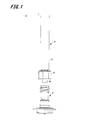
- FIG. 1 is an exploded side view of a drug injection device according to an embodiment of the present invention
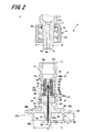
- FIG. 2 is an enlarged cross-sectional view of a main part of the drug injection device shown in FIG.
- the drug injection device 1 is used for injection of a drug by puncturing the surface of the skin with a needle tip.
- a drug injection device 1 for intradermal injection that injects a drug into the upper layer of the skin is shown.
- the skin is composed of three parts: epidermis, dermis, and subcutaneous tissue.
- the epidermis is a layer of about 50 to 200 ⁇ m from the skin surface, and the dermis is a layer of about 1.5 to 3.5 mm continuing from the epidermis.
- Influenza vaccines are generally administered subcutaneously or intramuscularly, and are therefore administered in the lower layer of the skin or deeper.
- the drug injection device 1 of the present embodiment is a drug injection device 1 for intradermal injection with such an upper layer portion of the skin as a target site.
- the drug injection device 1 of this embodiment includes an injection needle assembly 2 and a syringe (drug container) 3 to which the injection needle assembly 2 is detachably attached.
- a pusher for pushing out the medicine is inserted into the syringe 3.
- a lock mechanism 5 is provided at the end of the syringe 3 on the side connected to the injection needle assembly 2.
- the syringe 3 includes a syringe body 4, a medicine discharge portion 6 that is continuous with the syringe body 4, and a lock mechanism 5 that is provided on the outer periphery of the medicine discharge portion 6.
- the syringe body 4 is formed of a cylindrical member, and as shown in FIG. 2, the inside of the cylinder is a drug container 7 that stores a drug.
- the medicine discharge part 6 is provided at one end of the syringe body 4 in the axial direction, and is configured by a cylindrical member connected to the medicine container 7.
- the medicine discharge part 6 is formed in a male taper shape whose outer diameter is smaller than that of the syringe body 4 and becomes smaller toward the tip.
- the taper rate is expressed by a fraction such as A / 100 or a percentage such as A% when the diameter is reduced by A mm per 100 mm length, for example.
- medical agent discharge part 6 is comprised by N / 100.
- an extended portion 8 in which the diameter of the cylindrical hole 9 is increased is provided on the distal end side of the cylindrical hole 9 of the medicine discharge portion 6.
- the depth of the expanded portion 8, that is, the length from the distal end 6a of the medicine discharge portion 6 to the end surface 8a in the axial direction of the expanded portion 8 is formed to be about 0.4 mm to 0.6 mm.
- the dose is about 0.1 to 0.3 mL, which is smaller than subcutaneous injection or intramuscular injection. Therefore, it is necessary to reduce the dead volume of the syringe body 4 in order to eliminate the waste of the drug. is there. For this reason, the thickness of the medicine discharge part 6 is thicker than that of a general syringe, and the core pin of the mold may be broken during molding. In order to prevent the core pin from being broken, an extension portion 8 is provided.
- the tip 6a of the medicine discharge part 6 is formed with a flat surface perpendicular to the axial direction, and the outer shape of the flat surface, that is, the outer edge of the tip of the medicine discharge part 6 is formed in a circle.
- the flat surface of the tip 6 a of the drug discharge unit 6 and the side surface (tapered side surface) of the drug discharge unit 6 are connected by the outer edge of the tip of the drug discharge unit 6.
- the flat surface of the distal end 6 a of the medicine discharge section 6 comes into liquid-tight contact with the end surface of the elastic member 16 of the injection needle assembly 2 when attached to the injection needle assembly 2.
- a concave portion 6b into which a fitting claw 11a of the lock mechanism 5 described later is fitted is provided on the outer peripheral surface of the end portion (hereinafter, rear end) of the medicine discharge portion 6 on the syringe body 4 side.
- the syringe body 4 and the medicine discharge part 6 are formed of synthetic resin (plastic) as an example.
- synthetic resin plastic
- examples of the material of the synthetic resin include polycarbonate, polypropylene, polyethylene, and cycloolefin polymer.
- the lock mechanism 5 is provided so as to cover the outer peripheral surface of the medicine discharge section 6, and the lock main body section 10 is fixed to an injection needle assembly 2 described later, and the lock main body section 10 is fixed to the medicine discharge section 6. And a lock mechanism fixing part 11 for the purpose.
- the lock main body portion 10 is configured by a cylindrical member that surrounds the medicine discharge portion 6 coaxially.
- the lock main body portion 10 has a circular inner periphery, and the outer periphery is easy for a user to turn by hand. As an example, it is formed in a hexagonal shape.
- a female screw portion 23 is formed on the inner peripheral surface of the lock main body portion 10.
- the female screw portion 23 is formed so as to be screwable with a male screw portion 21 formed in a fitting portion 18 of the injection needle assembly 2 described later.
- the female screw portion 23 is formed of a double spiral screw groove.
- the lock mechanism fixing portion 11 is provided integrally with the lock main body portion 10 at the end of the lock main body portion 10 on the syringe main body 4 side.
- the lock mechanism fixing part 11 is configured by a hollow disk-like member provided so as to reduce the inner diameter of the lock main body part 10, and the inner peripheral surface facing the drug discharge part 6 of the lock mechanism fixing part 11 is A fitting claw 11 a that fits the medicine discharge unit 6 is provided.
- the inner diameter of the lock mechanism fixing part 11 is configured to be slightly larger than the outer diameter of the medicine discharge part 6.
- the fitting claws 11 a are provided so as to protrude in the radial direction from the inner peripheral surface of the lock mechanism fixing portion 11 that faces the medicine discharge portion 6, and the plurality of fitting claws 11 a are formed on the inner peripheral surface of the lock mechanism fixing portion 11. It is provided at equal intervals.
- the lock mechanism 5 having such a configuration is configured as a separate member from the syringe 3 and is fixed by fitting the fitting claw 11a into the recess 6b provided on the outer peripheral surface of the rear end of the medicine discharge unit 6. ing.
- the lock mechanism 5 can be formed using the same material as the syringe body 4 and the medicine discharge part 6.
- the injection needle assembly 2 includes a needle tube 12 and a needle hub 13 that holds the needle tube 12. Prior to connecting the syringe 3 to the injection needle assembly 2, the injection needle assembly 2 is detachably attached to the cap 50 as shown in FIG.
- the needle tube 12 is an ISO medical needle tube standard (ISO 9626: 1991 / Amd. 1: 2001 (E)) having a size of 26 to 33 gauge (outer diameter 0.2 to 0.45 mm), preferably Use 30 to 33 gauge.
- a needle tip 12 a having a blade surface is provided at the tip of the needle tube 12.
- the other end of the needle tube 12 opposite to the needle tip 12a is referred to as a “rear end 12b”.
- the length of the needle tube 12 in the axial direction on the blade surface (hereinafter referred to as “bevel length”) may be 1.4 mm (adult) or less, which is the thinnest thickness of the upper skin portion described later, and 33 What is necessary is just about 0.5 mm or more which is the bevel length when a short bevel is formed in the needle tube of a gauge. That is, the bevel length is preferably set in the range of 0.5 to 1.4 mm.
- the bevel length is more preferably such that the thinnest thickness of the upper skin layer is 0.9 mm (child) or less, that is, the bevel length B is in the range of 0.5 to 0.9 mm.
- the short bevel refers to a blade surface that is generally used for injection needles and forms an angle of 18 to 25 ° with respect to the longitudinal direction of the needle.
- the material of the needle tube 12 examples include stainless steel, but are not limited thereto, and aluminum, aluminum alloy, titanium, titanium alloy, and other metals can be used.
- the needle tube 12 may be a straight needle or a tapered needle having at least a part that is tapered. As the taper needle, the proximal end portion has a larger diameter than the needle distal end portion, and the intermediate portion may have a tapered structure. Further, the cross-sectional shape of the needle tube 12 may be not only a circle but also a polygon such as a triangle.
- the needle hub 13 includes a first member 14 provided with a fitting portion 18 into which the medicine discharge portion 6 of the syringe 3 is fitted, a second member 15 (holding portion of the present invention) that holds the needle tube 12, and a medicine injection device.
- the elastic member 16 is sandwiched between the medicine discharge part 6 and the second member 15 at the time of assembly.
- the first member 14 and the second member 15 constituting the needle hub 13 are formed as separate members, but may be formed integrally.
- the first member 14 is formed in a substantially cylindrical shape as a whole.
- a restricting portion 17 that restricts the force applied to the lock mechanism 5, a fitting portion 18 into which the medicine discharging portion 6 is inserted, and an elastic member 16 are inserted in this order from the side where the medicine discharging portion 6 is inserted.
- An intermediate portion 19 and an insertion portion 20 into which the second member 15 is inserted are formed.
- the cylindrical hole 18 b of the insertion portion 18 is set to a size corresponding to the medicine discharge portion 6 of the syringe 3, and an opening end on one end side thereof is a fitting inlet 18 a that is inserted into the medicine discharge portion 6.
- the diameter of the insertion portion 18 continuously decreases from the end of the insertion port 18a toward the insertion portion 20 side.
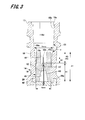
- FIG. 3 is an enlarged cross-sectional view of the insertion portion 18 portion of the first member 14.
- the configuration of the insertion portion 18 and the restriction portion 17 will be further described in detail with reference to FIG.
- the fitting part 18 has a fitting wall 18c fitted to the medicine discharge part 6 on the inner wall of the cylindrical hole 18b.
- the insertion part 18 has the guide wall 18d in the inner wall of the cylinder hole 18b at the side of the insertion port 18a.
- the fitting wall 18c is formed in a female taper shape in which the inner diameter of the cylindrical hole 18b continuously decreases from the fitting inlet 18a side toward the insertion portion 20 side.
- This taper shape is formed with a taper ratio of M> 100 where M> N.
- M is a positive number.
- the fitting wall 18c is formed so that the inner diameter of the cylindrical hole 18b can be fitted into the medicine discharge part 6 of the syringe 3.
- the diameter of the tip of the medicine discharge part 6 is K
- the diameter (maximum diameter) on the fitting inlet 18a side of the fitting wall 18c is Dmax
- the diameter (minimum diameter) on the insertion part 20 side of the fitting wall 18c is Dmin.
- the cylindrical hole 18b of the fitting wall 18c is formed so as to satisfy the relationship of Dmax> K> Dmin.
- the tip of the medicine discharge part 6 fitted to the position on the insertion part 20 side is positioned slightly from the position where the diameter of the cylindrical hole 18b becomes K.
- the guide wall 18d is formed by expanding the inner diameter of the cylindrical hole 18b on the fitting inlet 18a side.
- the guide wall 18d is preferably formed by expanding the inner diameter of the cylindrical hole 18b on the fitting inlet 18a side, compared to the case where the entire cylindrical hole 18b is formed by the fitting wall 18c having a taper ratio of M / 100.
- the guide wall 18d is preferably formed in a tapered shape such that the inner diameter of the cylindrical hole 18b decreases from the insertion port 18a side toward the insertion portion 20 side.
- the length of the guide wall 18d in the axial direction is, for example, about 0.5L to 2L when the length of the fitting wall 18c in the axial direction is L.
- the guide wall 18d and the fitting wall 18c are not connected in a stepped manner in order to prevent chemical leakage due to the tip of the medicine discharge part 6 being damaged. That is, as shown in FIG. 3, the angle d connecting the guide wall 18 d and the fitting wall 18 c with a tapered connection wall 18 e with a reduced diameter on the insertion portion 20 side or a connection wall 18 e formed with a curve is The obtuse angle (90 ° ⁇ d ⁇ 180 °) is preferable, and 120 ° ⁇ d ⁇ 180 ° is more preferable.
- a second screw portion (hereinafter referred to as a male screw portion 21) into which the female screw portion 23 of the lock mechanism 5 is screwed is formed on the outer peripheral surface of the fitting portion 18.
- the male screw portion 21 is formed of a double spiral screw thread.
- the male screw portion 21 may be a single spiral screw.
- the restricting portion 17 is formed of a cylindrical member that is provided at the end of the fitting inlet 18 a of the fitting portion 18 and has a cylindrical hole that is continuous with the cylindrical hole 18 b of the fitting portion 18.
- the outer peripheral surface of the restricting portion 17 and the outer peripheral surface of the fitting portion 18 are configured as continuous surfaces, and the outer diameter thereof is formed substantially the same as the outer diameter of the fitting portion 18 on the fitting inlet 18a side.
- the inner peripheral surface of the restricting portion 17 and the inner peripheral surface of the fitting portion 18 are configured as continuous surfaces, and the inner diameter thereof is slightly larger than the inner diameter of the fitting inlet 18 a of the fitting portion 18.
- the axial length of the restricting portion 17 is set so as to come into contact with the lock mechanism fixing portion 11 of the lock mechanism 5 when the drug injection device 1 is assembled.
- the restriction part 17 is a part provided to cancel out the pushing force applied to the lock mechanism 5 when the medicine discharge part 6 of the syringe 3 is pushed into the fitting part 18 of the injection needle assembly 2 and assembled. The function of the restriction unit 17 will be described in detail later.
- the cylindrical hole 22 of the insertion part 20 is set to a size corresponding to the base part 33 of the second member 15.
- the insertion portion 20 is provided with a fixing piece 34 connected to a connection piece 24 of the second member 15 described later.
- the fixing piece 34 is formed as a ring-shaped flange that protrudes radially outward from the distal end of the insertion portion 20.
- a flat surface 24b of the connection piece 24 provided on the second member 15 comes into contact with and is fixed to the fixed piece 34.
- Examples of the fixing method of the fixing piece 34 and the connection piece 24 include an adhesive, ultrasonic welding, laser welding, and a fixing screw.
- the intermediate portion 19 is provided between the insertion portion 20 and the insertion portion 18, and includes a cylindrical hole 26 having a smaller diameter than the cylindrical hole 22 of the insertion portion 20.
- the step surface at the boundary between the cylindrical hole 22 constituting the insertion part 20 and the cylindrical hole 26 constituting the intermediate part 19 becomes an engaging part 26a with which the elastic member 16 is engaged.
- a flange portion 42 described later of the elastic member 16 is engaged with the engaging portion 26a.
- the second member 15 is provided with a skin contact portion 30 that faces and / or contacts the skin.
- the skin contact portion 30 is disposed so as to cover the periphery of the needle tube 12 when the needle tube 12 is attached to the second member 15.
- the skin contact part 30 includes a substantially cylindrical base part 33, an adjustment part 31, a stabilization part 36, and a guide part 32.
- the base part 33 has end faces 33a and 33b perpendicular to the axial direction.
- the adjustment portion 31 is provided at the center of the end surface 33 a on one end side in the axial direction of the base portion 33, and includes a columnar convex portion protruding in the axial direction of the base portion 33.
- the axis of the adjustment part 31 is coincident with the axis of the base part 33.
- a through hole 25 through which the needle tube 12 passes is provided at the axis of the base portion 33 and the adjustment portion 31.
- the base portion 33 is provided with an injection hole 35 for injecting an adhesive (not shown) into the through hole 25.
- the injection hole 35 is opened on the outer peripheral surface of the base portion 33 and communicates with the through hole 25 so as to be substantially orthogonal to the through hole 25 although not shown in FIG. That is, the needle tube 12 is fixed to the base portion 33 by the adhesive injected from the injection hole 35 to the through hole 25.
- the rear end 12 b of the needle tube 12 protrudes from an end surface 33 b that is the other end of the base portion 33 in the axial direction.
- the base portion 33 is inserted into the first member 14 from the end surface 33b side, and the rear end 12b side of the needle tube 12 is inserted through a later-described insertion hole 43 of the elastic member 16. And the end surface 33b of the base part 33 is contact
- connection piece 24 is provided on the outer peripheral surface of the base portion 33.
- the connection piece 24 is formed as a ring-shaped flange that protrudes outward in the radial direction of the base portion 33, and has flat surfaces 24 a and 24 b that face the axial direction of the base portion 33.
- the first member 14 is connected to the flat surface 24 b of the connection piece 24.
- the distal end portion of the connection piece 24 is a guide portion 32. The guide portion 32 will be described in detail later.
- the end surface of the adjusting portion 31 is a needle protruding surface 31a from which the needle tip 12a side of the needle tube 12 protrudes.
- the needle projecting surface 31 a is formed as a plane orthogonal to the axial direction of the needle tube 12.
- the needle protruding surface 31a defines the depth of puncturing the needle tube 12 in contact with the surface of the skin when the needle tube 12 is punctured into the upper skin portion. That is, the depth at which the needle tube 12 is punctured into the upper skin layer is determined by the length of the needle tube 12 protruding from the needle protruding surface 31a (hereinafter referred to as “projection length L”).
- the thickness of the upper skin portion corresponds to the depth from the skin surface to the dermis layer, and is generally in the range of 0.5 to 3.0 mm. Therefore, the protruding length L of the needle tube 12 can be set in the range of 0.5 to 3.0 mm.
- the vaccine is generally administered to the upper arm, but when administration to the upper layer of the skin is considered, it is considered that the shoulder peripheral part where the skin is thick, particularly the deltoid part is suitable. Therefore, the thickness of the upper layer of the deltoid muscle was measured for 19 children and 31 adults. This measurement was performed by imaging the upper layer of the skin with high ultrasonic reflectivity using an ultrasonic measurement device (NP60R-UBM, high-resolution echo for small animals, Nepagene). In addition, since the measured value was logarithmic normal distribution, the range of MEAN ⁇ 2SD was obtained by geometric mean.
- the thickness of the upper skin layer of the deltoid muscle of the child was 0.9 to 1.6 mm.
- the thickness of the upper skin layer of the deltoid muscle of adults was 1.4 to 2.6 mm at the distal part, 1.4 to 2.5 mm at the central part, and 1.5 to 2.5 mm at the proximal part. It was. From the above, it was confirmed that the thickness of the upper skin layer in the deltoid muscle was 0.9 mm or more in the case of children and 1.4 mm or more in the case of adults. Therefore, in the injection at the upper layer portion of the deltoid skin, the protruding length L of the needle tube 12 is preferably set in the range of 0.9 to 1.4 mm.
- the blade surface of the needle tip 12a can be reliably positioned on the upper skin layer.
- the needle hole (chemical solution discharge port) that opens in the blade surface can be located in the upper layer portion of the skin at any position within the blade surface. Even if the drug solution outlet is located in the upper skin layer, if the needle tip 12a is deeply stabbed into the upper skin layer, the drug solution flows subcutaneously between the side surface of the end of the needle tip 12a and the cut skin. Therefore, it is important that the blade surface is surely in the upper skin part.
- the needle protruding surface 31a is formed such that the distance S from the peripheral edge to the peripheral surface of the needle tube 12 is 1.4 mm or less, and preferably in the range of 0.3 to 1.4 mm.
- the distance S from the peripheral edge of the needle protruding surface 31a to the peripheral surface of the needle tube 12 is set in consideration of the pressure applied to the blisters formed by administering the drug to the upper skin layer. That is, the needle projecting surface 31a is set to a size that is sufficiently smaller than the blisters formed on the upper layer portion of the skin and does not hinder the formation of blisters. As a result, it can be prevented that the needle protruding surface 31a presses the skin around the needle tube 12 and the administered medicine leaks.
- the stabilizing part 36 is formed in a cylindrical shape protruding from the flat surface 24 a of the connection piece 24 provided on the base part 33.
- the needle tube 12 and the adjustment unit 31 are disposed in the cylindrical hole of the stabilization unit 36.
- the stabilizing portion 36 is formed in a cylindrical shape that covers the periphery of the adjusting portion 31 through which the needle tube 12 penetrates, and is provided in the radial direction away from the needle tip 12 a of the needle tube 12.
- the end surface 36 a of the stabilizing portion 36 is located closer to the rear end 12 b of the needle tube 12 than the needle protruding surface 31 a of the adjusting portion 31.
- the needle projecting surface 31a first contacts the surface of the skin, and then contacts the end surface 36a of the stabilizing portion 36.
- the drug injection device 1 is stabilized by the end surface 36a of the stabilizing portion 36 coming into contact with the skin, and the needle tube 12 can be maintained in a posture substantially perpendicular to the skin.
- the needle tube 12 is skinned. It is possible to keep the posture substantially perpendicular to the angle.
- the axial distance between the end surface 36a of the stable portion 36 and the needle protruding surface 31a is preferably set to 1.3 mm or less.
- the inner diameter of the stable portion 36 is set to be equal to or larger than the diameter of the blister formed on the skin.
- the distance T from the inner wall surface of the stabilizing portion 36 to the peripheral edge of the needle protruding surface 31a is set to be in the range of 4 mm to 15 mm. Thereby, it can prevent that blister formation is inhibited by pressure being applied to a blister from the inner wall surface of stable part 36.
- the shortest distance T from the inner wall surface of the stabilizing portion 36 to the outer peripheral surface of the adjusting portion 31 is not particularly limited as long as it is 4 mm or more.
- the distance T is preferably set to 15 mm as a maximum in consideration of the thinness of the child's arm.
- the adjusting unit 31 does not enter the skin. Therefore, considering the distance T (4 mm or more) from the inner wall surface of the stable portion 36 to the peripheral edge of the needle protruding surface 31a and the diameter (about 0.3 mm) of the needle protruding surface 31a, the inner diameter of the stable portion 36 is set to 9 mm or more. can do.
- the shape of the stable part 36 is not limited to a cylindrical shape, and may be formed in a rectangular tube shape such as a quadrangular column or a hexagonal column having a cylindrical hole in the center, for example.
- the cap 50 is detachably fitted to the stabilizing portion 36 (see FIG. 4).
- the cap 50 covers the needle tip 12 a of the needle tube 12.
- needle tip 12a can be prevented from touching a user's fingertip.
- the used medicine injection device 1 or the needle assembly 2 can be always kept in a safe state, and the user can safely dispose of the used medicine injection device 1 or the needle assembly 2. It can be carried out.
- the guide portion 32 is a tip-side portion located on the outer side in the radial direction of the second member 15 relative to the stabilizing portion 36 of the connection piece 24.
- the guide portion 32 has a contact surface 32a that comes into contact with the skin.
- the contact surface 32 a is a part of the flat surface 24 a of the connection piece 24, and is a flat surface that is substantially parallel to the end surface 36 a of the stabilizing portion 36.
- the distance Y from the contact surface 32a of the guide portion 32 to the end surface 36a of the stable portion 36 punctures the needle tube 12 and the stable portion 36 by pressing the skin with an appropriate pressing force. Its length is set so that it can.
- An appropriate pressing force for the needle tube 12 and the stabilizing portion 36 is, for example, 3 to 20N.
- the height Y of the guide portion 32 is appropriately determined based on the inner diameter of the stable portion 36 and the length X from the distal end surface of the guide portion 32 to the outer peripheral surface of the stable portion 36 (hereinafter referred to as “guide portion length”). Is done. For example, when the inner diameter D of the stabilizing portion 36 is 12 mm and the guide portion length X is 3.0 mm, the guide portion height Y is set in the range of 2.3 to 6.6 mm.
- the elastic member 16 is disposed inside the cylindrical hole 26 that becomes the intermediate portion 19 of the first member 14, and is interposed between the first member 14 and the syringe 3.
- the elastic member 16 includes a deformable portion 40, a main body portion 41, and a flange portion 42 provided at one end of the main body portion 41 in the axial direction, and these are integrally formed.
- the main body portion 41 is formed in a substantially cylindrical shape, and the end surface 41 a opposite to the side on which the deformable portion 40 is formed abuts on the end surface 33 b of the base portion 33 of the second member 15. Further, the outer diameter of the main body portion 41 is formed to be slightly larger than the inner diameter of the inner wall surface on the insertion portion 20 side of the insertion portion 18 provided in the first member 14. Thereby, the elastic member 16 is liquid-tightly hold
- the flange portion 42 is provided on the outer peripheral surface of the main body portion 41 on the end surface 41 a side, and is formed in a ring shape that protrudes radially outward from the outer peripheral surface of the main body portion 41.
- the inner portion 19 is held larger than the inner diameter of the intermediate portion 19 and smaller than the inner diameter of the insertion portion 20. Therefore, one flat surface of the flange portion 42 abuts on the engaging portion 26 a formed by a step surface between the intermediate portion 19 and the insertion portion 20 of the first member 14, and the other flat surface is the second member 15. It contacts the end surface 33b of the base portion 33.
- the elastic member 16 is fixed to the needle hub 13 by sandwiching the flange portion 42 between the engaging portion 26 a of the first member 14 and the base portion 33 of the second member 15.
- the deformable portion 40 is composed of a cylindrical member provided on the opposite side of the end portion 41 a that contacts the base portion 33 of the main body portion 41, and the outer diameter thereof is the same as or larger than the outer diameter of the main body portion 41. It is formed a little small.
- the side surface of the deformable portion 40 is formed continuously with the side surface of the main body portion 41, and the inner wall surface of the deformable portion 40 is formed continuously with the inner wall surface of the main body portion 41.
- the end surface 40a on the opposite side to the main body 41 side of the deforming portion 40 is a contact surface that contacts the tip 6a of the medicine discharge portion 6. At the time of assembling the medicine injection device 1, the deformable portion 40 is pushed into the distal end 6 a of the medicine discharge portion 6 and is crushed to the main body portion 41 side.
- the user inserts the drug discharge portion 6 into the insertion portion 18 during use and connects the syringe 3 and the injection needle assembly 2 by fitting the drug discharge device 1. Assemble. Therefore, the depth and strength with which the medicine discharge portion 6 is fitted into the insertion portion 18 are different depending on the user. Furthermore, the fitting depth of the medicine discharge part 6 to the fitting part 18 also changes due to variations in the dimensional tolerance of the product.
- the deformation portion 40 is configured to follow the tip of the medicine discharge portion 6, thereby generating a difference in the fitting depth of the medicine discharge portion 6 to the insertion portion 18. Has the effect of reducing dead volume.
- transformation part 40 is comprised, and the dead volume by the difference in a fitting depth can be 10 microliters or less. Note that, in the elastic member 16, the main body portion 41 is also slightly deformed as the deformation portion 40 is deformed.
- the dimensions of the elastic member 16 will be described with reference to FIG.
- the axial length A3 of the deformable portion 40 is smaller than 35% with respect to the axial length A1 of the entire elastic member 16, the width of the elastic member 16 that can be deformed in the axial direction becomes small, and the user Depending on the difference in fitting depth, the dead volume generated by the difference becomes more than 10 ⁇ L.
- the axial length A3 of the deformable portion 40 is larger than 50% with respect to the axial length A1 of the entire elastic member 16, the amount of deformation of the elastic member becomes large, and liquid passing failure is possible. Increases nature.
- the axial length A3 of the deformable portion 40 is preferably configured to be 35% or more and 50% or less with respect to the axial length A1 of the entire elastic member 16.
- the elastic member 16 is provided with an insertion hole 43 through which the rear end 12b side of the needle tube 12 protruding from the end surface 33b of the base portion 33 is inserted in the axial direction of the main body portion 41 and the deformation portion 40. ing. On the inner wall surface of the insertion hole 43, an end surface side separation portion 46, a contact surface side separation portion 48, and a close contact portion 47 are formed.
- the end surface side separation portion 46 is configured by an inner wall surface of the insertion hole 43 on the main body portion 41 side, and forms an opening of the insertion hole 43 in the end surface 41 a of the main body portion 41.
- the end surface side separation portion 46 is separated from the outer peripheral surface of the needle tube 12, and is formed in a taper shape such that the diameter of the insertion hole 43 continuously increases toward the end surface 41a. Thereby, the rear end 12 b side of the needle tube 12 protruding from the end surface 33 b of the base portion 33 can be easily inserted into the insertion hole 43.
- the shape of the end face side separation portion 46 in the insertion hole 43 is not limited to a tapered shape as long as the needle tube 12 can be easily inserted into the insertion hole 43.
- the contact surface side separation portion 48 is configured by an inner wall surface of the insertion hole 43 on the deformation portion 40 side, and forms an opening of the insertion hole 43 in the end surface 40a on the deformation portion 40 side.
- the contact surface side separation portion 48 is separated from the outer peripheral surface of the needle tube 12. Further, the inner wall surface constituting the contact surface side separation portion 48 is formed substantially parallel to the axial direction of the deformation portion 40.
- the deforming portion 40 may be attached to the needle tube 12 when the medicine injection device 1 is assembled. There is a possibility of blocking the rear end 12b. The protrusion length of the needle tube 12 from the contact portion 47 to the deformation portion 40 side for preventing this will be described later.
- the inner wall surface constituting the contact surface side separation portion 48 in the insertion hole 43 is formed substantially parallel to the axial direction of the deformation portion 40, but the diameter of the insertion hole 43 increases from the close contact portion 47 toward the end surface of the deformation portion 40. You may form in the taper shape which becomes large continuously.
- the shape of the contact surface side separation portion 48 in the insertion hole 43 may be a shape that makes it difficult for the deformable portion 40 to block the needle hole of the needle tube 12 when the deformable portion 40 is elastically deformed.
- the contact portion 47 is formed between the end surface side separation portion 46 and the contact surface side separation portion 48, and is provided in the vicinity of the boundary between the main body portion 41 and the deformation portion 40.
- the close contact portion 47 is in liquid tight contact with the outer peripheral surface of the needle tube 12. Thereby, the medicine in the syringe 3 can be prevented from penetrating from between the needle tube 12 and the elastic member 16 to the second member 15 side of the needle hub 13.
- the protrusion length A2 (see FIG. 3) of the needle tube 12 from the close contact portion 47 to the contact surface side separation portion 48 side (insertion portion 18 side) is pushed by the deformable portion 40 of the elastic member 16 against the distal end 6a of the medicine discharge portion 6.
- the rear end 12b of the needle tube 12 When crushed, the rear end 12b of the needle tube 12 is exposed to the cylindrical hole 9 of the medicine discharge part 6 and is set to a length that does not damage the cylindrical hole 9 of the medicine discharge part 6.
- the exposure of the rear end 12b of the needle tube 12 to the side of the tube hole 9 of the medicine discharge part 6 allows the deformable part 40 to pass through without blocking all the needle holes, and allows the user to administer the medicine without burden. As long as it is possible.
- the medicine discharge portion 6 is inserted into the fitting portion 18.
- the deformed portion 40 crushed by the distal end 6a of the medicine discharge portion 6 blocks the rear end 12b of the needle tube 12, and the medicine cannot be discharged.
- the insertion of the medicine discharge portion 6 is performed.
- the length A2 of the needle tube 12 protruding from the close contact portion 47 toward the fitting portion 18 is set to a range of 45% or more and 245% or less with respect to the axial length A3 of the deformable portion 40. It is preferable. Further, the length A2 is preferably 1.4 mm or greater and 7.5 mm or less. Furthermore, the length A3 is preferably 2.5 mm or greater and 3.1 mm or less.
- the distal end 6 a of the medicine discharge portion 6 is deformed portion 40 of the elastic member 16 material.
- the tip 6a of the medicine discharge portion 6 and the end surface of the deformable portion 40 of the elastic member 16 come into liquid-tight contact.
- the needle tube 12 is exposed from the crushed distal end of the deformable portion 40 toward the drug discharge portion 6, whereby the tube hole 9 of the drug discharge portion 6 and the needle tube 12 communicate with each other.
- Examples of the material of the elastic member 16 include various rubber materials such as natural rubber and silicone rubber, various thermoplastic elastomers such as polyurethane and styrene, or elastic materials such as a mixture thereof.
- the injection needle assembly 2 configured as described above is manufactured as follows. First, the needle tube 12 is inserted into the through hole 25 of the base portion 33 of the second member 15. An adhesive is poured from an injection hole 35 formed in the base portion 33 in a state where the needle tip 12a of the needle tube 12 is protruded from the adjustment portion 31 by a predetermined length to be pierced in the skin, and the second member 15 and the needle tube 12 are poured. And fix them together. Next, the elastic member 16 is inserted into the intermediate portion 19 of the first member 14.
- the base portion 33 of the second member 15 is inserted into the insertion portion 20 of the first member 14, and the fixing piece 34 of the first member 14 is The guide part 32 of the second member 15 is bonded and fixed.
- the length A2 of the needle tube 12 protruding from the close contact portion 47 toward the fitting portion 18 is manufactured to be in a range of 45% or more and 245% or less with respect to the axial length A3 of the deformable portion 40.
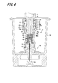
- the medicine discharge part 6 of the syringe 3 is inserted into the insertion part 18 of the injection needle assembly with the injection needle assembly 2 being accommodated in the cap 50.
- the distal end of the medicine discharge unit 6 is inserted into the cylindrical hole 18b from the insertion port 18a of the insertion unit 18.
- the inner diameter of the guide wall 18d is formed larger than the outer diameter of the distal end 6a of the medicine discharge part 6, the distal end 6a of the medicine discharge part 6 can be easily inserted into the fitting inlet 18a.
- the medicine discharge part 6 is further inserted into the cylindrical hole 18b. At this time, even if the medicine discharge section 6 is inclined and the tip 6a of the medicine discharge section 6 hits the connection wall 18e, the connection wall 18e is formed in a tapered shape so that the medicine discharge section 6 has a cylindrical hole 18b. It slides smoothly along the inner wall. For this reason, it can prevent that the front-end
- the medicine discharge portion 6 hits the fitting wall 18 c of the insertion portion 18. Since the taper rate of the fitting wall 18c is set to be larger than the taper rate of the drug discharging part 6, only the outer edge of the drug discharging part 6 hits the fitting wall 18c.
- FIG. 5 is an enlarged view of the deformed portion 40 in the state of FIG.
- the length of the needle tube 12 protruding from the close contact portion 47 toward the fitting portion 18 is set to a range of 45% or more and 245% or less with respect to the length of the deformable portion 40, thereby discharging the drug from the close contact portion 47.
- the distance Xa to the end surface 8a in the axial direction of the extended portion 8 of the portion 6 can be set to a predetermined range or less. A specific value of the distance Xa will be described in detail later.
- the distance Xa from the end surface 8a in the axial direction of the expansion portion 8 to the needle tube 12 is set such that the side in contact with the elastic member 16 is the positive direction and the drug storage portion 7 side is the end surface 8a of the expansion portion 8 as a reference (zero).
- the distance Xa is a positive value when the rear end 12b of the needle tube 12 is closer to the elastic member 16 than the end face 8a, and a negative value when the rear end 12b is closer to the medicine container 7 side.
- the first member 14 is formed of a synthetic resin.
- the fitting wall 18c is deformed so as to be recessed.
- medical agent discharge part 6 bites into the fitting wall 18c.
- medical agent discharge part 6 and the fitting wall 18c closely_contact
- the deformable portion 40 of the elastic member 16 is crushed by the medicine discharge portion 6. Then, the medicine enters the expansion part 8 provided at the tip of the medicine discharge part 6. Thereby, the end surface 8a in the axial direction of the expansion portion 8 and the tip 6a of the medicine discharge portion 6 and the end surface of the deformable portion 40 of the elastic member 16 are in fluid-tight contact. At this time, the needle tube 12 is communicated with the tube hole 9 of the drug discharge unit 6 by maintaining the state where the needle tube 12 is exposed to the drug discharge unit 6 side from the end of the deformed deformed portion 40.
- the medicine discharge portion 6 is inserted into the insertion portion 18 until the end surface of the restriction portion 17 contacts the bottom surface of the lock mechanism fixing portion 11, and the injection needle assembly 2 is locked to the drug discharge portion 6 by the lock mechanism 5. Thus, the assembly of the medicine injection device 1 is completed.
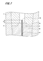
- FIG. 7 is an enlarged view of the deformed portion 40 in the state of FIG.
- the length of the needle tube 12 protruding from the contact portion 47 toward the fitting portion 18 is set in a range of 45% or more and 245% or less with respect to the length of the deformable portion 40, so that the assembly is completed.
- the rear end 12b of the needle tube 12 protrudes from the contact portion 47 toward the tube hole 9 of the medicine discharge portion 6 by a predetermined distance Xb. Thereby, the poor fluid passage due to the rear end 12b of the needle tube 12 being blocked by the deformable portion 40 can be suppressed.
- the distance Xb is a positive value when the rear end 12b of the needle tube 12 is closer to the elastic member 16 than the end face 8a, and a negative value when the rear end 12b is closer to the medicine container 7 as shown in FIG. Become.
- Xb is preferably 0 mm or greater and 6.0 mm or less.
- the insertion depth of the medicine discharge portion 6 into the insertion portion 18 is somewhat different depending on the user, but is only as long as the female screw portion 23 of the lock mechanism 5 and the male screw portion 21 of the insertion portion 18 are screwed together.
- the tip 6a of the medicine discharge part 6 is in liquid-tight contact with the deformation part 40 of the elastic member 16. That is, the insertion distance of the medicine discharge part 6 to the insertion part 18 up to a position where the restriction part 17 abuts on the lock mechanism fixing part 11 is the maximum insertion distance, and the restriction part 17 does not abut on the lock mechanism fixing part 11. It may be locked in position.
- abuts to the bottom face of the lock mechanism fixing
- the outer edge of the distal end of the medicine discharge portion 6 has a small circular shape, and when the medicine discharge portion 6 is inserted into the insertion portion 18, the outer edge of the small tip is pressed against the fitting wall 18c. Furthermore, the taper rate of the male taper shape of the medicine discharge part 6 is smaller than the taper rate of the female taper shape of the insertion part 18. As a result, the pressure with which the medicine discharge portion 6 is pressed against the fitting wall 18c is concentrated entirely in a narrow region of the fitting wall 18c where the outer edge of the medicine discharge portion 6 contacts. That is, since a slight gap is formed between the fitting wall 18 c and the side surface of the medicine discharge part 6, the force concentrates on the outer edge of the tip of the medicine discharge part 6.
- the fitting wall 18c of the injection needle assembly 2 and the side surface of the medicine discharge portion 6 rub against each other when assembling.
- the taper rate of the male taper shape of the medicine discharge portion 6 is smaller than the taper rate of the female taper shape of the insertion portion 18, so that even if the force is weak. The injection needle assembly 2 and the medicine discharge part 6 can be reliably fitted.
- the material of the first member 14 is not limited to a relatively soft material such as polypropylene, and any material such as polycarbonate or cycloolefin polymer can be used as long as the outer edge of the medicine discharge portion 6 can sufficiently penetrate into the fitting wall 18c. Thus, even a relatively hard material can be used.
- the protruding length of the needle tube 12 from the contact portion 47 to the contact surface side separation portion 48 side is such that the elastic member 16 is moved to the distal end 6 a of the drug discharge portion 6.
- the deformable portion 40 is crushed, the rear end 12b of the needle tube 12 is exposed to the cylindrical hole 9 of the drug discharging unit 6 without being blocked, and the length of the cylindrical hole 9 of the drug discharging unit 6 is not damaged. Is set to Thereby, the poor liquid flow can be prevented.
- the change of the liquid passing state is changed.
- the distance Xa was changed by changing the protruding length of the needle tube 12 from the contact portion 47.
- the contact position of the medicine discharge unit 6 shown in FIGS. 4 and 5 with the elastic member 16 is referred to as a reference contact position.
- the axial depth of the expansion part 8 of the medicine discharge part 6 is 0.4 to 0.6 mm, and the length of the elastic member 16 in the axial direction is 6.5 mm. 6.8 mm, deformed portion 40 has an outer diameter of 3.3 mm to 3.5 mm, deformed portion 40 has an axial length of 2.9 mm to 3.1 mm, and deformed portion 40 has a radial thickness of 0.9 mm. It is configured within the range of 1.1 mm or less.
- each drug injection device in which the distance Xa was set to 0.9 mm to 1.5 mm was assembled by applying a force larger than the average force applied by the user during assembly. Specifically, the medicine discharge part 6 is pushed and fitted to the insertion part 18 side with a load of 25 N, and the lock mechanism 5 is inserted into the insertion part 18 by rotating the syringe 3 with a connection torque of 0.26 N ⁇ m. And the syringe 3 and the needle assembly 2 were connected.
- medical agent injection apparatus which concerns on the experiment example assembled as mentioned above was measured.
- the peak load is larger than the peak load when the drug is discharged in a normal state drug injection device in which no poor liquid flow occurs, and the difference is larger than 15 N, the liquid flow is poor.
- the rate at which liquid failure occurred was examined. This criterion is set based on sensory test results that the user feels heavier than usual when the user presses the pusher to administer the drug. Table 1 below shows the experimental results of the drug injection device according to this experimental example.
- the distance Xa from the axial end surface 8a of the expansion portion 8 to the needle tube 12 is preferably ⁇ 5.3 mm or more. That is, a preferable range of the distance Xa is ⁇ 5.3 mm or more and 1.0 mm or less. Note that the distance from the end surface 8a in the axial direction of the expansion portion 8 to the needle tube 12 is based on the end surface 8a of the expansion portion 8 as a reference (zero), and the side in contact with the elastic member 16 is the positive direction, and the insertion portion 18 side is negative. Defined as direction.
- the length of the needle tube 12 protruding from the contact portion 47 toward the fitting inlet is in the range of 45% or more and 245% or less with respect to the deformed portion 40.
- the deforming part 40 is The rear end 12b of the needle tube 12 is not blocked, and liquid passing defects are suppressed.
- the taper rate of the medicine discharge portion and the taper rate of the insertion portion are different in the above-described embodiment, the effect of the present invention can be obtained even when the same.
- the configuration including the lock mechanism 5 configured as a member separate from the drug discharge unit 6 is shown, but the drug discharge unit 6 itself may be provided with a lock mechanism.
- a male screw portion is formed on the outer peripheral surface of the medicine discharge portion 6, and a female screw portion that is screwed to the male screw portion formed on the medicine discharge portion 6 is formed on the inner peripheral surface of the fitting portion 18.
- the medicine discharge part 6 can be fixed to the insertion part 18.
- SYMBOLS 1 Drug injection apparatus, 2 ... Injection needle assembly, 3 ... Syringe, 4 ... Syringe main body, 5 ... Lock mechanism, 6 ... Drug discharge part, 7 ... Drug accommodating part, 8 ... Expansion part, 10 ... Lock main body part, DESCRIPTION OF SYMBOLS 11 ... Lock mechanism fixing
Landscapes
- Health & Medical Sciences (AREA)
- Vascular Medicine (AREA)
- Engineering & Computer Science (AREA)
- Anesthesiology (AREA)
- Biomedical Technology (AREA)
- Heart & Thoracic Surgery (AREA)
- Hematology (AREA)
- Life Sciences & Earth Sciences (AREA)
- Animal Behavior & Ethology (AREA)
- General Health & Medical Sciences (AREA)
- Public Health (AREA)
- Veterinary Medicine (AREA)
- Infusion, Injection, And Reservoir Apparatuses (AREA)
Abstract
Description
1.注射針組立体及び薬剤注射装置の構成
2.薬剤注射装置の組み立て方法
[薬剤注射装置]
図1は、本発明の一実施形態に係る薬剤注射装置の分解側面図であり、図2は、図1に示した薬剤注射装置の要部を拡大して示した断面図である。薬剤注射装置1は、針先を皮膚の表面に穿刺し、薬剤の注射に用いられるものである。本実施形態では、一例として、皮膚上層部に薬剤を注射する皮内注射用の薬剤注射装置1を示している。
シリンジ3は、シリンジ本体4と、このシリンジ本体4に連続する薬剤排出部6と、薬剤排出部6の外周に設けられたロック機構5とを備えている。シリンジ本体4は、円筒部材で構成されており、図2に示すように、筒内部が薬剤を収容する薬剤収容部7になっている。薬剤排出部6は、シリンジ本体4の軸方向の一端に設けられており、薬剤収容部7に繋がる筒状の部材で構成されている。
注射針組立体2は、針管12と、針管12を保持する針ハブ13とで構成されている。また、注射針組立体2にシリンジ3を接続する前は、注射針組立体2は図4に示すように、キャップ50に着脱可能に取り付けられている。
第1部材14は、全体に略円筒形状に形成されている。第1部材14では、薬剤排出部6が嵌入される側から順に、ロック機構5にかかる力を制限する制限部17、薬剤排出部6が嵌入される嵌入部18、弾性部材16が挿入される中間部19、及び、第2部材15が挿入される挿入部20が形成されている。
第2部材15には、皮膚と対向及び/又は接触する皮膚接触部30が設けられている。皮膚接触部30は、第2部材15に針管12を取り付けた際に、針管12の周囲を覆うように配置される。この皮膚接触部30は、略円柱状のベース部33と、調整部31と、安定部36と、ガイド部32とを有する。
次に、弾性部材16について説明する。弾性部材16は、第1部材14の中間部19となる筒孔26内部に配置され、第1部材14とシリンジ3との間に介在される。この弾性部材16は、変形部40と、本体部41と、この本体部41の軸方向の一端に設けられたフランジ部42とを有しており、これらは一体に形成されている。
次に、注射針組立体2を薬剤排出部6に接続して薬剤注射装置1を組み立てる方法を説明する。図4及び図6に、注射針組立体2にシリンジ3の薬剤排出部6を嵌め込んで薬剤注射装置1を組み立てる様子を示す。図5は図4の要部の拡大図であり、図7は図6の要部の拡大図である。

Claims (6)
- 外径が先端に向かうにつれて小さくなる雄型のテーパ形状で形成された筒状の薬剤排出部を備える薬剤容器に接続される注射針組立体であって、
先端に皮膚に穿刺される針先を有する針管と、
前記薬剤排出部が挿入される嵌入口を有する雌型のテーパ形状で形成された嵌入部を有し、前記嵌入口側に前記針管の後端を突出させた状態で前記針管を保持する保持部と、
前記嵌入部内に設けられ、前記嵌入口側に突出した状態の前記針管を密着保持する密着部、及び、前記密着部から前記嵌入口側に延出し、前記薬剤排出部が当接した際に変形する変形部を備えた弾性部材とを有し、
前記変形部の長さが、前記弾性部材の長さに対して35%以上50%以下の範囲であり、
前記密着部から前記嵌入部側に突出した前記針管の長さが、前記変形部に対して45%以上245%以下の範囲であることを特徴とする
注射針組立体。 - 前記変形部の外径は3.3mm以上3.5mm以下の範囲であり、前記変形部の半径方向の厚みは0.9mm以上1.1mm以下の範囲である
請求項1に記載の注射針組立体。 - 外径が先端に向かうにつれて小さくなる雄型のテーパ形状で形成された筒状の薬剤排出部を備える薬剤容器と、
前記薬剤容器に接続される注射針組立体であって、
先端に皮膚に穿刺される針先を有する針管と、
前記薬剤排出部が挿入される嵌入口を有する雌型のテーパ形状で形成された嵌入部を有し、前記嵌入口側に前記針管の後端を突出させた状態で前記針管を保持する保持部と、
前記嵌入部内に設けられ、前記嵌入口側に突出した状態の前記針管を密着保持する密着部、及び、前記密着部から前記嵌入口側に延出し、前記薬剤排出部が当接した際に変形する変形部を備えた弾性部材とを有し、
前記変形部の長さが、前記弾性部材の長さに対して35%以上50%以下の範囲であり、
前記密着部から前記嵌入部側に突出した前記針管の長さが、前記変形部に対して45%以上245%以下の範囲である注射針組立体を有する
薬剤注射装置。 - 前記変形部の外径は3.3mm以上3.5mm以下の範囲であり、前記変形部の半径方向の厚みは0.9mm以上1.1mm以下の範囲である
請求項3に記載の薬剤注射装置。 - 前記薬剤排出部の筒孔の先端側には、前記薬剤排出部の筒孔の径が拡径された拡張部が設けられており、
前記拡張部の軸方向の深さは0.4mm以上0.6mm以下であり、
前記薬剤排出部を前記嵌入部に嵌入させ、前記薬剤排出部の先端が前記嵌入部の嵌入壁に嵌合し、かつ、前記薬剤排出部の先端が前記弾性部材の前記変形部に当接し、前記薬剤排出部と前記弾性部材とが基準の当接位置にある場合における、前記拡張部の軸方向の端面から前記針管の後端までの長さが1.0mm以下である、
請求項4に記載の薬剤注射装置。 - 前記薬剤排出部の前記雄型のテーパ形状がN/100のテーパ率であるときに、前記嵌入部の前記雌型のテーパ形状がM>Nとして、M/100のテーパ率で形成されている
請求項3~5のいずれか一項に記載の薬剤注射装置。
Priority Applications (3)
| Application Number | Priority Date | Filing Date | Title |
|---|---|---|---|
| EP15845873.7A EP3202439B1 (en) | 2014-09-29 | 2015-09-15 | Medicine injection device |
| JP2016551897A JP6652925B2 (ja) | 2014-09-29 | 2015-09-15 | 注射針組立体及び薬剤注射装置 |
| US15/470,831 US10335551B2 (en) | 2014-09-29 | 2017-03-27 | Needle assembly and drug injection device |
Applications Claiming Priority (2)
| Application Number | Priority Date | Filing Date | Title |
|---|---|---|---|
| JP2014-198435 | 2014-09-29 | ||
| JP2014198435 | 2014-09-29 |
Related Child Applications (1)
| Application Number | Title | Priority Date | Filing Date |
|---|---|---|---|
| US15/470,831 Continuation US10335551B2 (en) | 2014-09-29 | 2017-03-27 | Needle assembly and drug injection device |
Publications (1)
| Publication Number | Publication Date |
|---|---|
| WO2016052169A1 true WO2016052169A1 (ja) | 2016-04-07 |
Family
ID=55630211
Family Applications (1)
| Application Number | Title | Priority Date | Filing Date |
|---|---|---|---|
| PCT/JP2015/076120 Ceased WO2016052169A1 (ja) | 2014-09-29 | 2015-09-15 | 注射針組立体及び薬剤注射装置 |
Country Status (5)
| Country | Link |
|---|---|
| US (1) | US10335551B2 (ja) |
| EP (1) | EP3202439B1 (ja) |
| JP (1) | JP6652925B2 (ja) |
| TW (1) | TWI634919B (ja) |
| WO (1) | WO2016052169A1 (ja) |
Cited By (3)
| Publication number | Priority date | Publication date | Assignee | Title |
|---|---|---|---|---|
| KR20180082722A (ko) * | 2017-01-11 | 2018-07-19 | 김청균 | 중공원기둥 연통식의 일체형 주사용기 세트 |
| KR20180082723A (ko) * | 2017-01-11 | 2018-07-19 | 김청균 | 중공침 연통식의 일체형 주사용기 세트 |
| JPWO2023135905A1 (ja) * | 2022-01-14 | 2023-07-20 |
Families Citing this family (5)
| Publication number | Priority date | Publication date | Assignee | Title |
|---|---|---|---|---|
| WO2019176657A1 (ja) * | 2018-03-16 | 2019-09-19 | テルモ株式会社 | 皮内針及びその包装体並びに注射装置 |
| EP3569272B1 (de) * | 2018-05-14 | 2025-07-23 | SCHOTT Pharma Schweiz AG | Verschluss für einen behälter für pharmazeutische präparate und mit diesem verschluss versehener behälter |
| EP3903856A4 (en) * | 2018-12-25 | 2022-09-14 | Hirosaki University | DRUG ADMINISTRATION DEVICE AND SYSTEM |
| US20230117563A1 (en) * | 2020-03-31 | 2023-04-20 | Asti Corporation | Needle base unit, needle base unit production method and syringe device |
| CN114209927B (zh) * | 2020-12-21 | 2024-05-10 | 艾诺克医美科技(珠海)有限公司 | 一种减少内部气泡的多针注射针头 |
Citations (3)
| Publication number | Priority date | Publication date | Assignee | Title |
|---|---|---|---|---|
| US5041097A (en) * | 1990-02-26 | 1991-08-20 | Johnson Gerald W | Intravenous catheter fitting with protective end seal |
| JP2011212185A (ja) * | 2010-03-31 | 2011-10-27 | Terumo Corp | 薬剤投与器具及び薬剤注射装置 |
| JP2012517326A (ja) * | 2009-02-11 | 2012-08-02 | ベクトン・ディキンソン・アンド・カンパニー | 洗浄可能なカテーテルアセンブリを提供するためのシステムと方法 |
Family Cites Families (5)
| Publication number | Priority date | Publication date | Assignee | Title |
|---|---|---|---|---|
| US2864366A (en) * | 1957-04-04 | 1958-12-16 | Pfizer & Co C | Hypodermic syringe adapter |
| US5330435A (en) * | 1993-04-08 | 1994-07-19 | Vaillancourt Vincent L | Valve for a catheter assembly |
| EP2703028B1 (en) * | 2011-04-28 | 2021-03-24 | Terumo Kabushiki Kaisha | Hypodermic needle assembly and drug injection device |
| WO2012157313A1 (ja) * | 2011-05-13 | 2012-11-22 | テルモ株式会社 | 注射針ユニット |
| WO2012160852A1 (ja) * | 2011-05-20 | 2012-11-29 | テルモ株式会社 | 注射針組立体及び薬剤注射装置 |
-
2015
- 2015-09-15 JP JP2016551897A patent/JP6652925B2/ja active Active
- 2015-09-15 WO PCT/JP2015/076120 patent/WO2016052169A1/ja not_active Ceased
- 2015-09-15 EP EP15845873.7A patent/EP3202439B1/en active Active
- 2015-09-17 TW TW104130691A patent/TWI634919B/zh active
-
2017
- 2017-03-27 US US15/470,831 patent/US10335551B2/en active Active
Patent Citations (3)
| Publication number | Priority date | Publication date | Assignee | Title |
|---|---|---|---|---|
| US5041097A (en) * | 1990-02-26 | 1991-08-20 | Johnson Gerald W | Intravenous catheter fitting with protective end seal |
| JP2012517326A (ja) * | 2009-02-11 | 2012-08-02 | ベクトン・ディキンソン・アンド・カンパニー | 洗浄可能なカテーテルアセンブリを提供するためのシステムと方法 |
| JP2011212185A (ja) * | 2010-03-31 | 2011-10-27 | Terumo Corp | 薬剤投与器具及び薬剤注射装置 |
Cited By (4)
| Publication number | Priority date | Publication date | Assignee | Title |
|---|---|---|---|---|
| KR20180082722A (ko) * | 2017-01-11 | 2018-07-19 | 김청균 | 중공원기둥 연통식의 일체형 주사용기 세트 |
| KR20180082723A (ko) * | 2017-01-11 | 2018-07-19 | 김청균 | 중공침 연통식의 일체형 주사용기 세트 |
| JPWO2023135905A1 (ja) * | 2022-01-14 | 2023-07-20 | ||
| WO2023135905A1 (ja) | 2022-01-14 | 2023-07-20 | テルモ株式会社 | 針組立体および投与デバイス |
Also Published As
| Publication number | Publication date |
|---|---|
| EP3202439B1 (en) | 2022-01-12 |
| TW201611851A (en) | 2016-04-01 |
| JPWO2016052169A1 (ja) | 2017-08-24 |
| EP3202439A4 (en) | 2018-09-19 |
| JP6652925B2 (ja) | 2020-02-26 |
| TWI634919B (zh) | 2018-09-11 |
| EP3202439A1 (en) | 2017-08-09 |
| US20170197035A1 (en) | 2017-07-13 |
| US10335551B2 (en) | 2019-07-02 |
Similar Documents
| Publication | Publication Date | Title |
|---|---|---|
| JP6652925B2 (ja) | 注射針組立体及び薬剤注射装置 | |
| JP5604438B2 (ja) | 注射針組立体および薬剤注射装置 | |
| JP5667571B2 (ja) | 注射針組立体及び薬剤注射装置 | |
| JP5726741B2 (ja) | 注射針組立体および薬剤注射装置 | |
| JP6284595B2 (ja) | 注射針組立体及び薬剤注射装置 | |
| JP5719522B2 (ja) | 薬剤投与器具及び薬剤注射装置 | |
| JP5756793B2 (ja) | 注射針組立体及び薬剤注射装置 | |
| JP5894582B2 (ja) | 注射針組立体及び薬剤注射装置 | |
| JP5955838B2 (ja) | 注射針組立体及び薬剤注射装置 | |
| WO2016043074A1 (ja) | 検査システム、検査方法及び医療器具 | |
| WO2011040222A1 (ja) | 注射針組立体及び薬剤注射装置 | |
| WO2012160852A1 (ja) | 注射針組立体及び薬剤注射装置 | |
| WO2012157318A1 (ja) | 注射針組立体及び薬剤注射装置 | |
| JP6681331B2 (ja) | 注射針組立体、薬剤注射装置 | |
| WO2012157313A1 (ja) | 注射針ユニット | |
| WO2012157312A1 (ja) | 注射針ユニット | |
| WO2012132761A1 (ja) | 注射針ユニット、収納ケース、注射針組立体及び薬剤注射装置 |
Legal Events
| Date | Code | Title | Description |
|---|---|---|---|
| 121 | Ep: the epo has been informed by wipo that ep was designated in this application |
Ref document number: 15845873 Country of ref document: EP Kind code of ref document: A1 |
|
| ENP | Entry into the national phase |
Ref document number: 2016551897 Country of ref document: JP Kind code of ref document: A |
|
| REEP | Request for entry into the european phase |
Ref document number: 2015845873 Country of ref document: EP |
|
| WWE | Wipo information: entry into national phase |
Ref document number: 2015845873 Country of ref document: EP |
|
| NENP | Non-entry into the national phase |
Ref country code: DE |