WO2016056080A1 - 監視制御装置用試験装置 - Google Patents
監視制御装置用試験装置 Download PDFInfo
- Publication number
- WO2016056080A1 WO2016056080A1 PCT/JP2014/076921 JP2014076921W WO2016056080A1 WO 2016056080 A1 WO2016056080 A1 WO 2016056080A1 JP 2014076921 W JP2014076921 W JP 2014076921W WO 2016056080 A1 WO2016056080 A1 WO 2016056080A1
- Authority
- WO
- WIPO (PCT)
- Prior art keywords
- logic
- simulation
- unit
- control
- control logic
- Prior art date
- Legal status (The legal status is an assumption and is not a legal conclusion. Google has not performed a legal analysis and makes no representation as to the accuracy of the status listed.)
- Ceased
Links
Images










Classifications
-
- G—PHYSICS
- G05—CONTROLLING; REGULATING
- G05B—CONTROL OR REGULATING SYSTEMS IN GENERAL; FUNCTIONAL ELEMENTS OF SUCH SYSTEMS; MONITORING OR TESTING ARRANGEMENTS FOR SUCH SYSTEMS OR ELEMENTS
- G05B23/00—Testing or monitoring of control systems or parts thereof
- G05B23/02—Electric testing or monitoring
- G05B23/0205—Electric testing or monitoring by means of a monitoring system capable of detecting and responding to faults
- G05B23/0218—Electric testing or monitoring by means of a monitoring system capable of detecting and responding to faults characterised by the fault detection method dealing with either existing or incipient faults
- G05B23/0243—Electric testing or monitoring by means of a monitoring system capable of detecting and responding to faults characterised by the fault detection method dealing with either existing or incipient faults model based detection method, e.g. first-principles knowledge model
-
- G—PHYSICS
- G05—CONTROLLING; REGULATING
- G05B—CONTROL OR REGULATING SYSTEMS IN GENERAL; FUNCTIONAL ELEMENTS OF SUCH SYSTEMS; MONITORING OR TESTING ARRANGEMENTS FOR SUCH SYSTEMS OR ELEMENTS
- G05B19/00—Program-control systems
- G05B19/02—Program-control systems electric
- G05B19/04—Program control other than numerical control, i.e. in sequence controllers or logic controllers
- G05B19/042—Program control other than numerical control, i.e. in sequence controllers or logic controllers using digital processors
-
- G—PHYSICS
- G05—CONTROLLING; REGULATING
- G05B—CONTROL OR REGULATING SYSTEMS IN GENERAL; FUNCTIONAL ELEMENTS OF SUCH SYSTEMS; MONITORING OR TESTING ARRANGEMENTS FOR SUCH SYSTEMS OR ELEMENTS
- G05B23/00—Testing or monitoring of control systems or parts thereof
- G05B23/02—Electric testing or monitoring
Definitions
- the present invention relates to a test apparatus for a supervisory control apparatus that tests a supervisory control apparatus that controls equipment of the supervisory control system.
- the supervisory control system presents information from the equipment to be monitored, such as temperature, pressure, position, and other various sensors, to the operator or the supervisor, and the motor, valve, switch It is a system that controls various devices such as hydraulic devices, and is used in a wide range of fields such as power plants, chemical plants, power distribution facilities, and water and sewage systems.
- a typical supervisory control system includes a plurality of modules divided for each process, such as transmission / reception of signals to / from a device to be monitored and controlled, and these are combined by a communication path to perform various processes. It has been realized.
- the processing content of each module of the supervisory control system is a directed graph that shows the input / output direction of signals with arrows as shown in the circuit diagram
- Directed graph is a figure composed of edges (arrows) with vertices and directions. This is often expressed as Specifically, the processing content of each module includes a node (hereinafter also referred to as “arithmetic element”) indicating signal processing and a link (hereinafter referred to as “signal line”) that connects the nodes and indicates a signal flow. May be called).
- arithmetic element hereinafter also referred to as “arithmetic element”
- signal line hereinafter referred to as “signal line”
- control logic drawing representing the control logic of the monitoring control in the monitoring control system.
- the logic drawing is a plurality of processes corresponding to various modes (here, “process” refers to a so-called computer process.
- process refers to a so-called computer process.
- a plurality of processes corresponding to various modes “Is hereinafter referred to as” behavior ")
- the control logic tends to be complicated, and the complicated control logic is divided and described in a plurality of logic drawings.
- the number of target devices to be controlled is large, the number of logic drawings for controlling the devices is enormous.
- a test using a simulation (hereinafter sometimes referred to as “simulated logic”) is performed before performing a test using the actual control target device. carry out.
- the simulation simulates an operation corresponding to, for example, a pump device in an actual plant.
- Patent Document 1 As a conventional technique for performing a control logic test using simulation, there is a technique described in the conventional example of Patent Document 1.
- a tester inputs various data to a man-machine input function according to a test procedure manual, and the result processed in the control logic is simulated through a process output function.
- the process data is input to the control logic via the process input function
- the control result is output to the man-machine output function via the control logic
- the tester performs the man-machine output function and the test. Compare the contents with the procedure manual and judge pass / fail.
- test pattern management means for managing test patterns classified according to test contents, and precondition setting means for setting preconditions to be assumed when a test pattern is implemented in a plant control apparatus
- an operation simulation means for operating the operation command for executing the test pattern on the plant control apparatus in a simulated manner
- a history storage means for storing a history of the plant state resulting from the plant being controlled by the plant control apparatus
- a judgment means for judging a test result by comparing the plant state with a predetermined judgment criterion is provided, and the control logic test is automatically executed.
- Patent Document 1 is limited to automation limited to test execution, and does not consider a method for efficiently constructing a test environment.
- a test using an actual control target device it is necessary to connect the input / output of the control logic and the input / output of the control target device using a hardware signal line or the like.
- a test using simulation it is necessary to specify a simulation corresponding to each control logic and logically connect the input / output of the control logic and the input / output of the simulation.
- the conventional method does not consider a method for identifying an appropriate simulation for solving the above-described problem and connecting the input / output of the control logic and the input / output of the simulation. Since it is necessary to connect the input and output of the control logic and simulation, it takes time and effort to identify and connect the appropriate simulation to solve the above problems in the construction of the test environment. It was.
- the present invention has been made in view of the above-described problems, and a simulation corresponding to the control logic is appropriately specified so as to solve the above-described problem, and the input and output of the control logic and the simulation are connected without error. Therefore, it is an object of the present invention to provide a technique capable of preventing a test failure due to a connection error and performing a test efficiently.
- the monitoring control device test device comprises: A control logic storage unit for storing control logic, which is logic for controlling devices to be controlled by the monitoring control system, A control logic execution unit for executing the control logic extracted from the control logic storage unit; An input operation for taking out the control logic from the control logic storage unit and inputting it to the control logic execution unit, and an output operation for outputting an execution result executed by the control logic execution unit, to the control logic execution unit I / O command section to command, A simulation logic supply unit for supplying simulation logic which is logic for simulating the operation of the device; A simulation logic execution unit that extracts and executes the simulation logic from the simulation logic supply unit; A logic connection unit for connecting the control logic and the simulation logic; A test target instruction unit for instructing a device to be controlled by the control logic of the test target; A design book storage unit for storing a design book, which is a book used for designing the monitoring and control system of the device; A device characteristic acquisition unit that acquires, from the design book storage unit, device characteristics of a device to be controlled by the
- the simulation logic management unit based on the simulation logic management rule describing the relationship between the device characteristics and the simulation logic, from the device characteristics of the control target device acquired by the device characteristics acquisition unit, the test Identify the mock logic suitable for the target control logic
- the logic connection information generation unit connects the control logic to be tested and the simulation logic specified by the simulation logic management unit based on a logic connection rule that describes a connection method between the control logic and the simulation logic.
- the logic connection unit connects the test target control logic and the control target simulation logic using the logic connection information generated by the logic connection information generation unit.
- FIG. 1 is a block diagram illustrating a configuration of a test apparatus for a monitoring control device according to a first embodiment. It is a figure which shows an example of system
- FIG. 6 is a block diagram illustrating a configuration of a test apparatus for a monitoring control apparatus according to Embodiment 2.
- FIG. It is a figure which shows an example of an apparatus list. It is a figure which shows an example of a basic simulation logic. It is a figure which shows an example of a control logic. It is a figure which shows an example of a simulation logic. It is a figure which shows an example of a control logic. It is a figure which shows an example of a simulation logic. It is a figure which shows an example of the simulation logic management rule. It is a figure which shows an example of a logic connection rule. It is a figure which shows an example of logic connection information. It is a figure which shows an example of logic connection information.
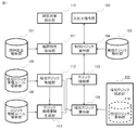
- FIG. 1 is a block diagram showing a configuration of a monitoring control device test apparatus according to Embodiment 1 of the present invention.
- the monitoring control device testing apparatus according to the first embodiment is configured from the following constituent elements (from the control logic storage unit 101 to the logic connection information generation unit 113 in the order of the symbols in the figure). Yes.
- the monitoring control device test apparatus includes a control logic storage unit 101, a simulation logic supply unit 102, an input / output command unit 103, a control logic execution unit 104, a logic connection unit 105, and a simulation logic execution unit 106. Yes.
- the monitoring control device testing apparatus includes a design book storage unit 107, a simulated logic management rule storage unit 108, a logic connection rule storage unit 109, a test target instruction unit 110, a device characteristic acquisition unit 111, and a simulated logic management.
- a unit 112 and a logic connection information generation unit 113 are added.
- a set of control target devices (for example, a set of device V-001 and device V-004 in the example) of the control logic to be tested is a test target instruction unit.
- the test target instruction unit 110 outputs a set of devices to the device characteristic acquisition unit 111.
- the device characteristic acquisition unit 111 receives a set of target devices from the test target instruction unit 110, acquires the device characteristics of the target device from the design book stored in the design book storage unit 107, and sends it to the simulation logic management unit 112. Output.
- the simulation logic management unit 112 inputs the device characteristics of the target device from the device characteristic acquisition unit 111 and, based on the simulation logic management rules stored in the simulation logic management rule storage unit 108, appropriate simulation logic corresponding to the target device. Is output to the logic connection information generation unit 113 and the simulation logic execution unit 106.
- the logic connection information generation unit 113 receives the simulation logic from the simulation logic management unit 112 and controls the control logic to be tested and the control logic based on the logic connection rules stored in the logic connection rule storage unit 109.
- Logic connection information for connecting the target simulation logic is generated and output to the logic connection unit 105.
- the logic connection unit 105 inputs the logic connection information from the logic connection information generation unit 113 and connects the control logic to be tested and the simulated logic.
- the control logic execution unit 104 executes the control logic stored in the control logic storage unit 101
- the simulation logic execution unit 106 executes the simulation logic supplied from the simulation logic supply unit 102
- the control logic test is performed by outputting the logic execution result subjected to the operation from the input / output command unit 103.
- FIG. 2 is a diagram illustrating an example of the system drawing 201 stored in the design book storage unit 107 as a design book.
- the design book includes a system drawing 201 illustrating devices to be monitored and controlled by the monitoring control system.
- the tank 202, three pumps 203, 204, 205, five valves 206, 207, 208, 209, 210 which correspond to devices to be monitored and controlled in the monitoring control system, are connected. It consists of piping.
- Each device has a device name unique to each device such as “T-001” and “P-001” and device information such as “TYPE-A” and “TYPE-B”.
- the device information “TYPE-A” and “TYPE-B” indicate that the valves have different specifications, and the specifications of the input signals necessary for opening the valve from the initial state to the closed state are different.
- FIG. 3 and 5 are diagrams showing an example of the control logic stored in the control logic storage unit 101.
- the control logic 301 is the control logic of the device “V-001” that is the device type “valve (TYPE-A)”, and the control logic 501 is the control of the device “V-004” that is the device type “valve (TYPE-B)”.
- the control logic is a logic for monitoring and controlling the device.
- the control logic includes an arithmetic element that performs various arithmetic operations on a signal, and a signal line that connects the arithmetic elements and indicates a signal flow. It is out.
- FIG. 4 and 6 are diagrams illustrating an example of the simulation logic stored in the simulation logic storage unit 116 of the simulation logic supply unit 102.
- the simulation logic 401 is a simulation logic “logic C1” of the device “V-001” which is the device type “valve (TYPE-A)”, and the simulation logic 601 is a device “V-” which is the device type “valve (TYPE-B)”.
- 004 is a simulation logic" logic C2 ".
- the simulation logic is a logic for simulating the operation of a device such as a valve.
- an arithmetic element that performs various operations on a signal and arithmetic elements are connected to each other. And a signal line indicating a signal flow.
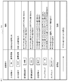
- FIG. 7 is a diagram showing description rules and explanations of arithmetic elements and signal lines included in the control logic and the simulation logic. Note that FIG. 7 shows only a part of the types of arithmetic elements and signal lines, and various other arithmetic elements are included in the control logic and the simulation logic.
- the control logic 301, 501 and the simulation logic 401, 601 are a plurality of arithmetic elements (input operator, output operator, logical product operator, logical sum operator, negation operator, flip-flop, on-delay) and these arithmetic operations.
- Signal lines (digital lines indicated by solid lines) for connecting the elements.
- the logic connection information 801 is the logic connection information of the device “V-001”
- the logic connection information 901 is the logic connection information of the device “V-004”.
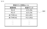
- FIG. 10 is a diagram illustrating an example of the simulation logic management rules stored in the simulation logic management rule storage unit 108. The simulation logic used for each device type is described.
- FIG. 11 is a diagram illustrating an example of the logic connection rules stored in the logic connection rule storage unit 109.
- the logic connection rule 1101 is a valve logic connection rule.
- the device characteristic acquisition unit 111 acquires the system drawing 201 including the devices “V-001” and “V-004” from the design book storage unit 107, and acquires the devices “V-001” and “V-004”.
- Get device characteristics indicate the characteristics of each device, for example, device name, device type, device type, device manufacturer, device controller type, and the like.
- the device type of the device “V-001” is “valve (TYPE-A)”
- the device type of the device “V-004” is “valve (TYPE-B)”.
- TYPE-A valve
- TYPE-B valve
- the simulation logic management unit 112 identifies the simulation logic of each device based on the simulation logic management rules stored in the simulation logic management rule storage unit 108. Specifically, based on the simulation logic management rule 1001, since the device type of the device “V-001” is “valve (TYPE-A)”, the corresponding simulation logic is “logic C1” 401. get. Similarly, since the device type of the device “V-004” is “valve (TYPE-B)”, the corresponding simulation logic is acquired as “logic C2” 601.
- the logic connection information generation unit 113 generates logic connection information based on the logic connection rules stored in the logic connection rule storage unit 109.
- “[0-9]” described in the logic connection rule 1101 of the valve means a number from 0 to 9, and the simulated logic to be connected from the signal name of the input / output operator included in the control logic Specify the signal name.
- this logic connection rule 1101 in the device “V-001”, “V1-CL-O” and “CL-IN”, “V1-OP-O”, “OP-IN”, “V1-CLD” And “CL-OUT”, “V1-OPD”, and “OP-OUT” are connected to generate logic connection information 801.
- the simulation logic suitable for the control logic is identified from the device characteristics acquired from the design book, and the logic connection rule Based on the above, the control logic and the simulation logic are connected. Therefore, since the simulation logic and the control logic can be automatically connected without generating or preparing the logic connection information for each device, it is possible to save labor and time for that amount.
- the monitoring control device testing apparatus specifies the simulation logic of the devices “V-001” and “V-004” and connects the control logic and the simulation logic. Although the operation has been described, the simulation logic can be specified and connected by operating in the same manner for other devices.
- the connection between the control logic and the simulation logic as shown in FIG. 3 and FIG. 4 has been described.
- the present invention is not limited to such a simple case. For example, when the operation of the supervisory control system becomes large-scale, it becomes difficult to describe the behavior in one logic drawing, and it is often expressed by a plurality of drawings. Even in that case, the same operation is possible.
- control logic and the simulation logic are described as function block diagrams composed of arithmetic elements that perform various operations on signals and signal lines that connect the arithmetic elements and indicate the flow of signals. Although it was done, it is not limited to the logic description method. The same operation is possible even when the logic is described using another language, for example, a ladder logic or an instruction list.
- the device characteristic is described as being the device type acquired from the system drawing.
- the device characteristics may be, for example, the device type or the type of device controller, and there are many types of simulated logic by using multiple device characteristics together.
- the same operation as described above can be performed by using the device characteristic acquisition unit 111 for analyzing the corresponding design book.
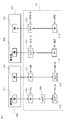
- FIG. FIG. 12 is a block diagram showing the configuration of the monitoring control apparatus test apparatus according to Embodiment 2 of the present invention.
- the same or similar components as those described in the first embodiment are denoted by the same reference numerals, and different points will be mainly described.
- the test apparatus for monitoring control apparatus is composed of the components (control logic storage unit 101 to simulated logic generation unit 115) described below.
- the monitoring control device test apparatus according to the present embodiment includes a basic simulation logic storage unit 114 and a simulation logic generation unit 115 in the simulation logic supply unit 102 in the monitoring control device test apparatus according to the first embodiment. It is made up of what it has.
- the process until the device characteristic acquisition unit 111 acquires the device characteristic and outputs it to the simulated logic management unit 112 is the same as that of the first embodiment.
- the simulation logic management unit 112 inputs the device characteristics of each device from the device property acquisition unit 111, and based on the simulation logic management rules stored in the simulation logic management rule storage unit 108, the basic simulation logic corresponding to each device is obtained. It specifies and outputs to the logic connection information generation part 113 and the simulation logic generation part 115.
- the simulation logic generation unit 115 acquires the basic simulation logic from the basic simulation logic storage unit 114, generates the simulation logic of the target device from the acquired basic simulation logic, and generates the logic connection information generation unit 113 and the simulation logic execution unit 106. Output to.
- the subsequent steps are the same as in the first embodiment.
- FIG. 13 is a diagram showing an example of a device list 1301 stored in the design book storage unit 107 as a design book. That is, the design book according to the present embodiment includes a device list 1301 that describes the specifications of devices to be monitored and controlled by the monitoring control system. In the example shown in FIG. 13, specifications of a tank, three pumps, five valves, and two devices X corresponding to devices to be monitored and controlled in the monitoring control system are described. Each device is accompanied by a device name, device type, manufacturer, and device type. The device types “D-001” and “D-002” of the device type “device X” indicate that the devices have different formats, and the number of states of the devices is different.
- FIG. 14 is a diagram illustrating an example of basic simulation logic stored in the basic simulation logic storage unit 114.
- the basic simulation logic includes calculation elements that perform various calculations on signals, and signal lines that connect the calculation elements and indicate the flow of signals, as in the simulation logic.
- the basic mock logic is a logic that is a basic pattern of mock logic, and the mock logic is composed of one type of basic mock logic or a combination of a plurality of types of mock logic (specifically, The M-001 simulation logic shown in FIG. 16 is composed of one type of basic simulation logic shown in FIG. 14, and the M-002 simulation logic shown in FIG. 18 is two types of basic simulation logic shown in FIG. Example).
- the basic simulation logic 1401 is the simulation logic “logic D” of the device type “device X”. “[AZ]” described in the signal name of the basic simulation logic 1401 means an alphabetic character from A to Z.
- FIG. 15 and 17 are diagrams illustrating an example of the control logic stored in the control logic storage unit 101.
- FIG. A control logic 1501 is a control logic of a device “M-001” that is a device type “D-001” that controls two states of “A” and “B”, and a control logic 1701 is “A”, “B”, This is the control logic of the device “M-002”, which is the device type “D-002” that controls the three states of “C”.
- the simulation logic 1601 is the simulation logic of the device “M-001”, and the simulation logic 1801 is the simulation logic of the device “M-002”.
- FIG. 19 is a diagram illustrating an example of the simulation logic management rules stored in the simulation logic management rule storage unit 108. The basic simulation logic used for each device type is described.
- FIG. 20 is a diagram illustrating an example of a logic connection rule stored in the logic connection rule storage unit 109.
- the logic connection rule 2001 is a logic connection rule for the device X.
- the logic connection information 2101 is the logic connection information of the device “M-001”
- the logic connection information 2201 is the logic connection information of the device “M-002”.
- the device characteristic acquisition unit 111 acquires the device list 1301 including the devices “M-001” and “M-002” from the design book storage unit 107, and acquires the devices “M-001” and “M-002”. ”Is acquired. Specifically, it acquires from the device list 1301 that the device type of the device “M-001” and the device “M-002” is “device X”.
- the simulation logic management unit 112 specifies the basic simulation logic of each device based on the simulation logic management rules stored in the simulation logic management rule storage unit 108. Specifically, based on the simulation logic management rule 1901, since the device types of the device “M-001” and the device “M-002” are “device X”, the basic simulation logic is “logic D” 1401. To get that.
- the simulation logic generation unit 115 has a basic simulation logic because the input / output operators of the control logic 1501 of the device “M-001” are the output operator “M1-AO” and the input operator “M1-AD”. From 1401, a simulation logic 1601 is generated by replacing the signal name from “[AZ] -IN” to “A-IN” and from “[AZ] -OUT” to “A-OUT”. In addition, the simulation logic generation unit 115 sets the input / output operators of the control logic 1701 of the device “M-001” as output operators “M2-AO”, “M2-BO”, and input operators “M2-BO”.
- the logic connection information generation unit 113 generates logic connection information based on the logic connection rules stored in the logic connection rule storage unit 109.
- “[0-9]” described in the logic connection rule 2001 means a number from 0 to 9
- “[AZ]” means an alphabetic character from A to Z, and is included in the control logic.
- the signal name of the simulated logic to be connected is determined from the signal name of the input / output operator to be connected. Based on this logic connection rule 2001, the logic connection information 2101 of the device “M-001” and the logic connection information 2201 of the device “M-002” are generated.
- the simulation logic is generated from the basic simulation logic, and the generated simulation logic and the control logic are connected. Therefore, since the simulation logic can be automatically generated from the basic simulation logic without generating or preparing the simulation logic for each device, it is possible to save the labor and time for that operation.
- the simulation logic of the monitoring control apparatus testing apparatus has been described with respect to the operation generated from one type of basic simulation logic.
- a combination of simulation logics for example, in the case of combination of two types of basic simulation logics when “DELAY” is 100 and “DELAY” is 10 in the basic simulation logic of FIG. 14
Landscapes
- Physics & Mathematics (AREA)
- General Physics & Mathematics (AREA)
- Engineering & Computer Science (AREA)
- Automation & Control Theory (AREA)
- Testing And Monitoring For Control Systems (AREA)
Abstract
Description
典型的な監視制御システムにおいては、監視制御の対象となる機器と信号の送受信を行うなど、処理ごとに分割されたモジュールを複数備え、これらが通信経路によって結合されることにより、多様な処理が実現されている。
監視制御システムの制御対象となる機器を制御するためのロジックである制御ロジックを格納する制御ロジック格納部、
前記制御ロジック格納部から取り出した前記制御ロジックを実行する制御ロジック実行部、
前記制御ロジック格納部から前記制御ロジックを取り出し前記制御ロジック実行部に入力する入力操作と、前記制御ロジック実行部で実行された実行結果を出力する出力操作と、を前記制御ロジック実行部に対して指令する入出力指令部、
前記機器の動作を模擬するためのロジックである模擬ロジックを供給する模擬ロジック供給部、
前記模擬ロジックを前記模擬ロジック供給部から取り出して実行する模擬ロジック実行部、
前記制御ロジックと前記模擬ロジックとを接続するロジック接続部、
試験対象の制御ロジックの制御対象となる機器が指示される試験対象指示部、
前記機器を前記監視制御システムの設計のために使用する図書である設計図書を格納する設計図書格納部、
前記試験対象指示部に指示された試験対象の制御ロジックの制御対象となる機器の機器特性を、前記設計図書格納部から取得する機器特性取得部、
前記機器特性と前記模擬ロジックとの関連が記載された模擬ロジック管理ルールに基づき、前記試験対象の制御ロジックに適した模擬ロジックを特定する模擬ロジック管理部、
前記制御ロジックと前記模擬ロジックとの接続方法が記載されたロジック接続ルールに基づき、前記試験対象の制御ロジックと、前記模擬ロジック管理部により特定された模擬ロジックとを接続するためのロジック接続情報を生成するロジック接続情報生成部、を備えた前記機器の監視制御装置用試験装置であって、
前記ロジック接続部は、前記ロジック接続情報生成部が生成したロジック接続情報を用いて、前記試験対象の制御ロジックと、前記制御対象の模擬ロジックとを接続するものである。
ロジック接続情報生成部は、前記制御ロジックと前記模擬ロジックとの接続方法が記載されたロジック接続ルールに基づき、前記試験対象の制御ロジックと、前記模擬ロジック管理部により特定された模擬ロジックとを接続するためのロジック接続情報を生成し、
前記ロジック接続部は、前記ロジック接続情報生成部が生成したロジック接続情報を用いて、前記試験対象の制御ロジックと、前記制御対象の模擬ロジックとを接続する。これにより、制御ロジックに対応する模擬ロジックが適切に特定され、制御ロジックと模擬ロジックの入出力を誤りなく接続されることにより、接続の誤りによる試験の失敗を防ぎ、効率よく試験を実施することが可能となる。
図1は、本発明の実施の形態1による監視制御装置用試験装置の構成を示すブロック図である。図1において、本実施の形態1に係る監視制御装置用試験装置は、次に説明する構成要素(図中の符号順に、制御ロジック格納部101からロジック接続情報生成部113まで)から構成されている。
図1において、監視制御装置用試験装置は、制御ロジック格納部101、模擬ロジック供給部102、入出力指令部103、制御ロジック実行部104、ロジック接続部105、模擬ロジック実行部106により構成されている。本発明の形態1による監視制御装置用試験装置は、設計図書格納部107、模擬ロジック管理ルール格納部108、ロジック接続ルール格納部109、試験対象指示部110、機器特性取得部111、模擬ロジック管理部112、ロジック接続情報生成部113が追加されて構成されている。
図11は、ロジック接続ルール格納部109に格納されているロジック接続ルールの一例を示す図である。ロジック接続ルール1101は、弁のロジック接続ルールである。
試験対象指示部110に、機器「V-001」と機器「V-004」が試験対象として入力されたと仮定して、以降説明する。
以上の説明において、「CL-O」の「CL」はクローズ、「O」はアウト、「OP」はオープン、「CLD」はクローズ表示用、「OPD」はオープン表示用、をそれぞれ意味する(以下同様)。
図12は、本発明の実施の形態2による監視制御装置用試験装置の構成を示すブロック図である。なお、本実施の形態に係る監視制御装置用試験装置において、実施の形態1で説明した構成要素と同一または類似するものについては同じ符号を付し、異なる点を中心に説明する。
図20は、ロジック接続ルール格納部109に格納されているロジック接続ルールの一例を示す図である。ロジック接続ルール2001は、機器Xのロジック接続ルールである。
試験対象指示部110に、機器「M-001」と機器「M-002」が試験対象として入力されたと仮定して、以降説明する。
模擬ロジック管理部112は、模擬ロジック管理ルール格納部108に格納された模擬ロジック管理ルールに基づき、各機器の基本模擬ロジックを特定する。具体的には、模擬ロジック管理ルール1901に基づき、機器「M-001」及び機器「M-002」の機器種類が「機器X」であることから、基本模擬ロジックが「ロジックD」1401であることを取得する。
103 入出力指令部、104 制御ロジック実行部、
105 ロジック接続部、106 模擬ロジック実行部、
107 設計図書格納部、108 模擬ロジック管理ルール格納部、
109 ロジック接続ルール格納部、110 試験対象指示部、
111 機器特性取得部、112 模擬ロジック管理部、
113 ロジック接続情報生成部、114 基本模擬ロジック格納部、
115 模擬ロジック生成部、116 模擬ロジック格納部。
Claims (4)
- 監視制御システムの制御対象となる機器を制御するためのロジックである制御ロジックを格納する制御ロジック格納部、
前記制御ロジック格納部から取り出した前記制御ロジックを実行する制御ロジック実行部、
前記制御ロジック格納部から前記制御ロジックを取り出し前記制御ロジック実行部に入力する入力操作と、前記制御ロジック実行部で実行された実行結果を出力する出力操作と、を前記制御ロジック実行部に対して指令する入出力指令部、
前記機器の動作を模擬するためのロジックである模擬ロジックを供給する模擬ロジック供給部、
前記模擬ロジックを前記模擬ロジック供給部から取り出して実行する模擬ロジック実行部、
前記制御ロジックと前記模擬ロジックとを接続するロジック接続部、
試験対象の制御ロジックの制御対象となる機器が指示される試験対象指示部、
前記機器を前記監視制御システムの設計のために使用する図書である設計図書を格納する設計図書格納部、
前記試験対象指示部に指示された試験対象の制御ロジックの制御対象となる機器の機器特性を、前記設計図書格納部から取得する機器特性取得部、
前記機器特性と前記模擬ロジックとの関連が記載された模擬ロジック管理ルールに基づき、前記試験対象の制御ロジックに適した模擬ロジックを特定する模擬ロジック管理部、
前記制御ロジックと前記模擬ロジックとの接続方法が記載されたロジック接続ルールに基づき、前記試験対象の制御ロジックと、前記模擬ロジック管理部により特定された模擬ロジックとを接続するためのロジック接続情報を生成するロジック接続情報生成部、を備えた前記機器の監視制御装置用試験装置であって、
前記ロジック接続部は、前記ロジック接続情報生成部が生成したロジック接続情報を用いて、前記試験対象の制御ロジックと、前記制御対象の模擬ロジックとを接続することを特徴とする監視制御装置用試験装置。 - 前記模擬ロジック供給部は、前記模擬ロジックを格納する模擬ロジック格納部、もしくは、
前記模擬ロジックの基本パターンである基本模擬ロジックを格納する基本模擬ロジック格納部および前記基本模擬ロジックから前記模擬ロジックを生成する模擬ロジック生成部、を含むことを特徴とする請求項1に記載の監視制御装置用試験装置。 - 前記制御ロジック格納部と前記模擬ロジック供給部とは、前記監視制御システムを構成する各モジュールの信号処理をするノードと、このノード間を繋ぎ信号の流れを示すリンクとを備えることを特徴とする請求項1または請求項2に記載の監視制御装置用試験装置。
- 前記設計図書は、前記監視制御システムの制御対象となる機器の系統を図示した系統図、あるいは前記制御対象となる機器の仕様を記載した機器仕様書を有し、
前記機器の名称、種類、形式、メーカー、及び、機器制御用の制御器の種類のうち、少なくとも1つを前記機器の機器特性の情報として含むことを特徴とする請求項1から3のいずれか1項に記載の監視制御装置用試験装置。
Priority Applications (5)
| Application Number | Priority Date | Filing Date | Title |
|---|---|---|---|
| CN201480082405.2A CN106796430B (zh) | 2014-10-08 | 2014-10-08 | 监视控制装置用测试装置 |
| US15/504,228 US10295996B2 (en) | 2014-10-08 | 2014-10-08 | Test device for monitoring control device |
| JP2016552747A JP6400114B2 (ja) | 2014-10-08 | 2014-10-08 | 監視制御装置用試験装置 |
| PCT/JP2014/076921 WO2016056080A1 (ja) | 2014-10-08 | 2014-10-08 | 監視制御装置用試験装置 |
| EP14903506.5A EP3206101B1 (en) | 2014-10-08 | 2014-10-08 | Test device for monitoring control device |
Applications Claiming Priority (1)
| Application Number | Priority Date | Filing Date | Title |
|---|---|---|---|
| PCT/JP2014/076921 WO2016056080A1 (ja) | 2014-10-08 | 2014-10-08 | 監視制御装置用試験装置 |
Publications (1)
| Publication Number | Publication Date |
|---|---|
| WO2016056080A1 true WO2016056080A1 (ja) | 2016-04-14 |
Family
ID=55652739
Family Applications (1)
| Application Number | Title | Priority Date | Filing Date |
|---|---|---|---|
| PCT/JP2014/076921 Ceased WO2016056080A1 (ja) | 2014-10-08 | 2014-10-08 | 監視制御装置用試験装置 |
Country Status (5)
| Country | Link |
|---|---|
| US (1) | US10295996B2 (ja) |
| EP (1) | EP3206101B1 (ja) |
| JP (1) | JP6400114B2 (ja) |
| CN (1) | CN106796430B (ja) |
| WO (1) | WO2016056080A1 (ja) |
Cited By (1)
| Publication number | Priority date | Publication date | Assignee | Title |
|---|---|---|---|---|
| JP2024122011A (ja) * | 2023-02-28 | 2024-09-09 | メタウォーター株式会社 | 運転方案生成方法、運転方案生成プログラム及び運転方案生成装置 |
Families Citing this family (6)
| Publication number | Priority date | Publication date | Assignee | Title |
|---|---|---|---|---|
| JP6563187B2 (ja) * | 2014-11-12 | 2019-08-21 | 株式会社東芝 | 分散制御システム、制御装置及び制御方法 |
| US10359757B2 (en) * | 2015-05-13 | 2019-07-23 | Mitsubishi Electric Corporation | Control logic diagram analysis device and control logic diagram analysis method |
| CN109799806B (zh) * | 2019-01-18 | 2020-10-30 | 南方电网科学研究院有限责任公司 | 一种阀控装置仿真测试方法与系统 |
| JP7294488B1 (ja) * | 2022-03-30 | 2023-06-20 | 横河電機株式会社 | 情報処理装置、情報処理方法および情報処理プログラム |
| CN115390548B (zh) * | 2022-08-30 | 2025-08-29 | 中控技术股份有限公司 | 控制回路的识别方法、装置、存储介质及电子设备 |
| TWI833602B (zh) * | 2023-03-10 | 2024-02-21 | 華邦電子股份有限公司 | 測試裝置以及測試方法 |
Citations (3)
| Publication number | Priority date | Publication date | Assignee | Title |
|---|---|---|---|---|
| JPH09114689A (ja) * | 1995-10-20 | 1997-05-02 | Toyo Eng Corp | Plcテスト支援システム |
| JP2001175318A (ja) * | 1999-12-15 | 2001-06-29 | Toshiba Corp | プラント制御装置用試験装置 |
| JP2014157444A (ja) * | 2013-02-15 | 2014-08-28 | Mitsubishi Electric Corp | エンジニアリングツール監視システム |
Family Cites Families (15)
| Publication number | Priority date | Publication date | Assignee | Title |
|---|---|---|---|---|
| US3927371A (en) * | 1974-02-19 | 1975-12-16 | Ibm | Test system for large scale integrated circuits |
| US6725435B2 (en) * | 2002-01-25 | 2004-04-20 | Logicvision, Inc. | Method and program product for completing a circuit design having embedded test structures |
| JP2004133650A (ja) * | 2002-10-10 | 2004-04-30 | Mitsubishi Heavy Ind Ltd | 制御用ロジックのシミュレーション検証方法及びシミュレーション検証用パソコン |
| US6941243B1 (en) * | 2003-01-17 | 2005-09-06 | Unisys Corporation | Using conversion of high level descriptive hardware language into low level testing language format for building and testing complex computer products with contract manufacturers without proprietary information |
| JP4050196B2 (ja) * | 2003-07-09 | 2008-02-20 | 三菱電機株式会社 | 監視制御回路を有する電子制御装置 |
| US8036760B2 (en) * | 2005-10-04 | 2011-10-11 | Fisher-Rosemount Systems, Inc. | Method and apparatus for intelligent control and monitoring in a process control system |
| US7408336B2 (en) * | 2005-10-26 | 2008-08-05 | International Business Machines Corporation | Importation of virtual signals into electronic test equipment to facilitate testing of an electronic component |
| CN101978405B (zh) * | 2008-02-15 | 2013-04-03 | 因文西斯系统公司 | 为过程控制系统检验和操作员训练自动生成仿真的系统和方法 |
| JP2009223861A (ja) * | 2008-03-19 | 2009-10-01 | Hitachi Information & Communication Engineering Ltd | 論理検証システム |
| US8135571B2 (en) * | 2008-08-14 | 2012-03-13 | International Business Machines Corporation | Validating manufacturing test rules pertaining to an electronic component |
| CN101887111A (zh) * | 2009-05-15 | 2010-11-17 | 施耐德电器工业公司 | 用于可编程逻辑控制器模拟量模块的自动测试系统及方法 |
| JP5395642B2 (ja) * | 2009-12-01 | 2014-01-22 | 株式会社日立製作所 | プラント制御装置の試験支援装置および試験支援方法 |
| JP5489958B2 (ja) * | 2010-11-25 | 2014-05-14 | 三菱電機株式会社 | 試験テーブル生成装置及びその方法 |
| US9703562B2 (en) * | 2013-03-16 | 2017-07-11 | Intel Corporation | Instruction emulation processors, methods, and systems |
| CN108139741B (zh) * | 2015-10-12 | 2021-10-08 | 费希尔-罗斯蒙特系统公司 | 一种用于调试过程工厂的系统和方法 |
-
2014
- 2014-10-08 CN CN201480082405.2A patent/CN106796430B/zh active Active
- 2014-10-08 EP EP14903506.5A patent/EP3206101B1/en active Active
- 2014-10-08 US US15/504,228 patent/US10295996B2/en active Active
- 2014-10-08 WO PCT/JP2014/076921 patent/WO2016056080A1/ja not_active Ceased
- 2014-10-08 JP JP2016552747A patent/JP6400114B2/ja active Active
Patent Citations (3)
| Publication number | Priority date | Publication date | Assignee | Title |
|---|---|---|---|---|
| JPH09114689A (ja) * | 1995-10-20 | 1997-05-02 | Toyo Eng Corp | Plcテスト支援システム |
| JP2001175318A (ja) * | 1999-12-15 | 2001-06-29 | Toshiba Corp | プラント制御装置用試験装置 |
| JP2014157444A (ja) * | 2013-02-15 | 2014-08-28 | Mitsubishi Electric Corp | エンジニアリングツール監視システム |
Non-Patent Citations (1)
| Title |
|---|
| See also references of EP3206101A4 * |
Cited By (1)
| Publication number | Priority date | Publication date | Assignee | Title |
|---|---|---|---|---|
| JP2024122011A (ja) * | 2023-02-28 | 2024-09-09 | メタウォーター株式会社 | 運転方案生成方法、運転方案生成プログラム及び運転方案生成装置 |
Also Published As
| Publication number | Publication date |
|---|---|
| EP3206101A1 (en) | 2017-08-16 |
| EP3206101A4 (en) | 2018-06-20 |
| CN106796430B (zh) | 2019-02-22 |
| EP3206101B1 (en) | 2019-07-03 |
| US10295996B2 (en) | 2019-05-21 |
| CN106796430A (zh) | 2017-05-31 |
| JP6400114B2 (ja) | 2018-10-03 |
| US20170277175A1 (en) | 2017-09-28 |
| JPWO2016056080A1 (ja) | 2017-06-08 |
Similar Documents
| Publication | Publication Date | Title |
|---|---|---|
| JP6400114B2 (ja) | 監視制御装置用試験装置 | |
| US11435728B2 (en) | I/O virtualization for commissioning | |
| US10878140B2 (en) | Plant builder system with integrated simulation and control system configuration | |
| US10586172B2 (en) | Method and system of alarm rationalization in an industrial control system | |
| Oppelt et al. | Integrated virtual commissioning an essential activity in the automation engineering process: From virtual commissioning to simulation supported engineering | |
| JP2020052812A (ja) | エンジニアリングシステム及びエンジニアリング方法 | |
| US10198536B2 (en) | Simulation system, method for carrying out a simulation, control system, and computer program product | |
| US20170147427A1 (en) | System and method for software simulation for testing a safety manager platform | |
| US20140172402A1 (en) | Simulation system, method for carrying out a simulation, guidance system, and computer program product | |
| US20140222408A1 (en) | Simulation system, method of carrying out a simulation, guidance system and computer program product | |
| Valiev et al. | Pattern-design software of automated control systems | |
| EP4141648A1 (en) | Method and system for generating automation domain objects using knowledge from another automation domain object | |
| JP5907857B2 (ja) | ロジック図面及び試験テーブル作成装置 | |
| Kelly et al. | Application of the digraph method in system fault diagnostics | |
| EP4653960A1 (en) | Method for testing a process plant system | |
| Isermann | The role of digital control in engineering thirty-second bernard price memorial lecture 1983 | |
| JP2025182774A (ja) | 自動検証システム、自動検証方法、及び、自動検証プログラム | |
| Mononen | Implementation of Process Simulation for Marine Automation System | |
| Sim et al. | Modules, version and variability management in automation engineering of machine and plant manufacturing | |
| Smogeli | Managing DP system software-A life-cycle perspective | |
| Laitinen | Development of Virtual Test Environment for ABB Azipod Interface Unit | |
| Armanes et al. | ABS Virtual Commissioning: The Use of Simulation Models to Satisfy Class Requirements | |
| Blaney et al. | Digital bus technology in new coal-fired plants. | |
| Gajardo et al. | DYNAMIC SIMULATION FOR ACID PLANT OPERATOR TRAINNING IN CHQUICAMATA | |
| Khaled | Distributed Control Systems-DCS-An application on YOKOGAWA CENTUM VP |
Legal Events
| Date | Code | Title | Description |
|---|---|---|---|
| 121 | Ep: the epo has been informed by wipo that ep was designated in this application |
Ref document number: 14903506 Country of ref document: EP Kind code of ref document: A1 |
|
| ENP | Entry into the national phase |
Ref document number: 2016552747 Country of ref document: JP Kind code of ref document: A |
|
| WWE | Wipo information: entry into national phase |
Ref document number: 15504228 Country of ref document: US |
|
| REEP | Request for entry into the european phase |
Ref document number: 2014903506 Country of ref document: EP |
|
| WWE | Wipo information: entry into national phase |
Ref document number: 2014903506 Country of ref document: EP |
|
| NENP | Non-entry into the national phase |
Ref country code: DE |