WO2016056280A1 - パイロットチェック弁 - Google Patents
パイロットチェック弁 Download PDFInfo
- Publication number
- WO2016056280A1 WO2016056280A1 PCT/JP2015/069601 JP2015069601W WO2016056280A1 WO 2016056280 A1 WO2016056280 A1 WO 2016056280A1 JP 2015069601 W JP2015069601 W JP 2015069601W WO 2016056280 A1 WO2016056280 A1 WO 2016056280A1
- Authority
- WO
- WIPO (PCT)
- Prior art keywords
- valve
- packing
- port
- check valve
- pilot check
- Prior art date
- Legal status (The legal status is an assumption and is not a legal conclusion. Google has not performed a legal analysis and makes no representation as to the accuracy of the status listed.)
- Ceased
Links
Images

Classifications
-
- F—MECHANICAL ENGINEERING; LIGHTING; HEATING; WEAPONS; BLASTING
- F16—ENGINEERING ELEMENTS AND UNITS; GENERAL MEASURES FOR PRODUCING AND MAINTAINING EFFECTIVE FUNCTIONING OF MACHINES OR INSTALLATIONS; THERMAL INSULATION IN GENERAL
- F16K—VALVES; TAPS; COCKS; ACTUATING-FLOATS; DEVICES FOR VENTING OR AERATING
- F16K37/00—Special means in or on valves or other cut-off apparatus for indicating or recording operation thereof, or for enabling an alarm to be given
- F16K37/0025—Electrical or magnetic means
- F16K37/0033—Electrical or magnetic means using a permanent magnet, e.g. in combination with a reed relays
-
- F—MECHANICAL ENGINEERING; LIGHTING; HEATING; WEAPONS; BLASTING
- F16—ENGINEERING ELEMENTS AND UNITS; GENERAL MEASURES FOR PRODUCING AND MAINTAINING EFFECTIVE FUNCTIONING OF MACHINES OR INSTALLATIONS; THERMAL INSULATION IN GENERAL
- F16K—VALVES; TAPS; COCKS; ACTUATING-FLOATS; DEVICES FOR VENTING OR AERATING
- F16K15/00—Check valves
- F16K15/02—Check valves with guided rigid valve members
- F16K15/021—Check valves with guided rigid valve members the valve member being a movable body around which the medium flows when the valve is open
-
- F—MECHANICAL ENGINEERING; LIGHTING; HEATING; WEAPONS; BLASTING
- F16—ENGINEERING ELEMENTS AND UNITS; GENERAL MEASURES FOR PRODUCING AND MAINTAINING EFFECTIVE FUNCTIONING OF MACHINES OR INSTALLATIONS; THERMAL INSULATION IN GENERAL
- F16K—VALVES; TAPS; COCKS; ACTUATING-FLOATS; DEVICES FOR VENTING OR AERATING
- F16K15/00—Check valves
- F16K15/02—Check valves with guided rigid valve members
- F16K15/025—Check valves with guided rigid valve members the valve being loaded by a spring
- F16K15/026—Check valves with guided rigid valve members the valve being loaded by a spring the valve member being a movable body around which the medium flows when the valve is open
-
- F—MECHANICAL ENGINEERING; LIGHTING; HEATING; WEAPONS; BLASTING
- F16—ENGINEERING ELEMENTS AND UNITS; GENERAL MEASURES FOR PRODUCING AND MAINTAINING EFFECTIVE FUNCTIONING OF MACHINES OR INSTALLATIONS; THERMAL INSULATION IN GENERAL
- F16K—VALVES; TAPS; COCKS; ACTUATING-FLOATS; DEVICES FOR VENTING OR AERATING
- F16K15/00—Check valves
- F16K15/02—Check valves with guided rigid valve members
- F16K15/06—Check valves with guided rigid valve members with guided stems
- F16K15/063—Check valves with guided rigid valve members with guided stems the valve being loaded by a spring
-
- F—MECHANICAL ENGINEERING; LIGHTING; HEATING; WEAPONS; BLASTING
- F16—ENGINEERING ELEMENTS AND UNITS; GENERAL MEASURES FOR PRODUCING AND MAINTAINING EFFECTIVE FUNCTIONING OF MACHINES OR INSTALLATIONS; THERMAL INSULATION IN GENERAL
- F16K—VALVES; TAPS; COCKS; ACTUATING-FLOATS; DEVICES FOR VENTING OR AERATING
- F16K15/00—Check valves
- F16K15/18—Check valves with actuating mechanism; Combined check valves and actuated valves
- F16K15/182—Check valves with actuating mechanism; Combined check valves and actuated valves with actuating mechanism
- F16K15/1826—Check valves which can be actuated by a pilot valve
-
- F—MECHANICAL ENGINEERING; LIGHTING; HEATING; WEAPONS; BLASTING
- F16—ENGINEERING ELEMENTS AND UNITS; GENERAL MEASURES FOR PRODUCING AND MAINTAINING EFFECTIVE FUNCTIONING OF MACHINES OR INSTALLATIONS; THERMAL INSULATION IN GENERAL
- F16K—VALVES; TAPS; COCKS; ACTUATING-FLOATS; DEVICES FOR VENTING OR AERATING
- F16K37/00—Special means in or on valves or other cut-off apparatus for indicating or recording operation thereof, or for enabling an alarm to be given
- F16K37/0025—Electrical or magnetic means
- F16K37/0041—Electrical or magnetic means for measuring valve parameters
Definitions
- the present invention relates to a pilot check valve that uses a pilot pressure in controlling the flow of a working fluid.
- a pilot check valve is provided in a fluid pressure circuit for driving a fluid pressure cylinder in order to appropriately control the flow of the working fluid (see, for example, Japanese Utility Model Publication No. 3-25080).
- a fluid pressure circuit in which a fluid pressure cylinder is used as an ascending / descending cylinder, a head side pressure chamber and a rod side pressure chamber of the cylinder are connected to a pressure supply source via a switching valve, and the rod side pressure chamber and the switching valve are connected.
- a pilot check valve is disposed in the flow path between the two.
- the pilot check valve is arranged to be slidable in the axial direction so as to face the poppet valve body, and the poppet valve body is pressed when the pilot pressure is applied.
- a pilot piston A pilot pressure is applied to the pilot check valve as the supply pressure is applied to the head-side pressure chamber of the cylinder.
- the poppet valve body resists the elastic force of the spring under the pressure action based on the working fluid.
- the working fluid flows into the rod-side pressure chamber of the cylinder and pushes up the piston of the cylinder.
- the pressure difference between the front and rear of the poppet valve body disappears, and the poppet valve body is seated on the valve seat under the action of the elastic force of the spring.
- the conventional pilot check valve has not been provided with a function for detecting that the valve is closed. Further, since the poppet valve body and the pilot piston are separated from each other, and the position of the pilot piston and the state of the poppet valve body do not always correspond to each other, even if the position of the pilot piston is detected, the poppet valve body It does not detect whether or not the person is seated. For this reason, the conventional pilot check valve cannot properly detect whether or not the valve is closed.
- the present invention has been made in view of such problems, and an object thereof is to provide a pilot check valve that can appropriately detect whether or not the valve is closed.
- the present invention provides a flow path body having a first port and a second port, and at least a part of the flow path body is slidably disposed in the flow path body.
- a movable body that operates in a direction, and an inclined lip portion that is attached to the movable body and that can be displaced between a valve closing position and a valve opening position integrally with the movable body and that can be elastically deformed in a radial direction.
- a packing capable of slidingly contacting the inner peripheral surface of the flow path body at the lip portion, and a detector for detecting whether the movable body is positioned at a position where the packing is positioned at the valve closed position;
- the packing allows the flow of the working fluid from the first port side to the second port side in the valve closed position, and the second port side to the first port side. Prevent the flow of working fluid In valve opening position, wherein communicating the second port with the first port, characterized in that.
- the movable body and the packing are integrally displaced in the axial direction, whether or not the valve is in the closed state is detected by detecting the position of the movable body (the packing is closed). It is possible to appropriately detect whether or not it is located. Further, when the packing is in the valve closed position, the packing permits the flow of the working fluid from the first port side to the second port side, while blocking the flow of the working fluid from the second port side to the first port side. Therefore, the check valve function can be effectively exhibited even when the pilot pressure is released.
- the seal start position is located between the valve close position and the valve open position. It is preferable to start contact with the inner peripheral surface of the flow path body.
- the detector when the packing moves from the valve open position toward the valve closed position, the detector preferably outputs a signal after the packing exceeds the seal start position.
- the lip portion of the packing slidably contacts the inner peripheral surface of the flow path body over a predetermined range in the axial direction when moving from the valve open position toward the valve close position.
- the sealing mechanism by the contact between the lip portion and the inner peripheral surface has an axial overlap region, and the influence of the detection error and hysteresis of the detector can be eliminated by this overlap region. It is possible to prevent the detector from outputting a signal when the valve is not closed. That is, when the detector outputs a signal, the valve is always in a completely closed state, so that the reliability of the position detection function can be improved.
- the inner peripheral surface of the flow path body includes a seal region that presses and contacts the lip when the packing is located at the valve closed position, and the packing is located at the valve open position. And a non-seal region spaced from the lip portion, and the non-seal region preferably has a larger inner diameter than the seal region.
- the communication state and the non-communication state of the first port and the second port can be easily and reliably switched depending on the axial position of the packing in the flow path body.
- the pilot check valve includes a packing support member that surrounds the packing and prevents the lip portion from deforming more than a predetermined amount outward in the radial direction.
- This configuration can prevent excessive deformation of the lip and improve the durability of the packing.
- the packing support member is provided with a passage that allows the working fluid to flow from the first port side to the lip portion.
- pilot check valve of the present invention it is possible to appropriately detect whether or not the valve is closed.
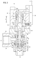
- FIG. 1 is a cross-sectional view of a pilot check valve 10 according to an embodiment of the present invention in a closed state
- FIG. 3 is a cross-sectional view of the pilot check valve 10 in an open state
- the pilot check valve 10 includes a flow channel body 16 having a first port 12 and a second port 14, an operating rod 18 disposed in the flow channel body 16 so as to be slidable in the axial direction (arrow X direction), A packing 20 attached to the actuating rod 18, a packing support member 22 attached to the actuating rod 18, a pilot mechanism 24 connected to the flow path body 16, and a detector 25 provided in the pilot mechanism 24 Is provided.
- the flow path body 16 is a member that forms a flow path of a working fluid (for example, air).
- the flow path body 16 includes a hollow first body 26 having the first port 12 and a hollow second body 28 having the second port 14.
- the first body 26 has an insertion portion 30 into which the second body 28 is inserted on the side opposite to the first port 12, and surrounds the second body 28 in the insertion portion 30.
- An annular space 32 communicating with the first port 12 is formed between the insertion portion 30 and the second body 28.
- the second body 28 includes a coupling portion 34 that is coupled to the pilot mechanism portion 24, and a hollow cylindrical sleeve portion 36 that protrudes from the coupling portion 34 in a direction opposite to the pilot mechanism portion 24.
- the coupling portion 34 may be in the form of a nut having a hexagonal cross section.
- the sleeve portion 36 is a portion that is inserted into the insertion portion 30 of the first body 26 described above.
- Annular seal members 38 and 40 are disposed on the outer peripheral portion of the sleeve portion 36 at intervals in the axial direction.
- One seal member 38 is disposed between the sleeve portion 36 and the insertion portion 30.
- a hollow cylindrical spacer member 42 is disposed between the insertion portion 30 and the sleeve portion 36, and the other seal member 40 is disposed between the sleeve portion 36 and the spacer member 42.
- another seal member 44 is disposed between the spacer member 42 and the insertion portion 30.
- one or more (two in the illustrated example) side holes 46 are provided between the seal member 38 and the seal member 40.
- the hollow portion of the first body 26 and the hollow portion of the second body 28 communicate with each other through a side hole 46.
- a diameter-expanded portion 48 is provided on the second port 14 side of the side hole 46, that is, on the inner peripheral surface between the side hole 46 and the second port 14.
- the enlarged diameter portion 48 is larger than the inner diameter of the portion of the sleeve portion 36 between the side hole 46 and the enlarged diameter portion 48 (hereinafter referred to as the “reduced diameter portion 50”).
- the reduced diameter portion 50 has a constant inner diameter along the axial direction.
- the operating rod 18 is disposed so as to be slidable in the axial direction (X direction) within the sleeve portion 36 of the second body 28. Specifically, an annular projecting portion 52 projecting radially outward is provided at the axial intermediate portion of the operating rod 18, and the seal member 56 is inserted into the seal mounting groove 54 provided in the annular projecting portion 52. Installed. The seal member 56 prevents fluid from leaking from the second body 28 to the pilot mechanism 24 side.
- a packing 20 and a packing support member 22 are attached to the end of the operating rod 18 (on the side opposite to the pilot mechanism 24; the X1 direction).
- the bushing 58 is fixed (screwed in the illustrated example) to the distal end portion of the operating rod 18, so that the packing 20 and the packing support member 22 are fixed to the distal end portion of the operating rod 18. Therefore, when the operating rod 18 moves in the axial direction, the packing 20 and the packing support member 22 also move in the axial direction integrally with the operating rod 18.
- the packing 20 is made of an elastic body such as rubber (for example, butyl rubber, isoprene rubber, butadiene rubber, silicone rubber, etc.) and has a hollow cylindrical shape as a whole. Specifically, the packing 20 has a cylindrical base portion 60 parallel to the axial direction. And an annular lip portion 62 that protrudes from the outer peripheral portion of the cylindrical base portion 60 and is elastically deformable in the radial direction.
- rubber for example, butyl rubber, isoprene rubber, butadiene rubber, silicone rubber, etc.
- the packing 20 allows the flow of the working fluid from the first port 12 side to the second port 14 side in the valve closed position shown in FIG. 1, while the working fluid from the second port 14 side to the first port 12 side. Block the flow of Moreover, the packing 20 makes the 1st port 12 and the 2nd port 14 communicate in the valve opening position shown in FIG.
- the lip portion 62 is inclined toward the distal end direction (X1 direction) of the operating rod 18.
- the lip portion 62 extends in the circumferential direction at the outer peripheral portion of the cylindrical base portion 60.
- the inner surface of the tip end portion of the lip portion 62 is opposed to and spaced apart from the outer peripheral surface of the cylindrical base 60.
- an annular groove 63 that is recessed toward the X2 direction is formed.
- the outer diameter of the lip portion 62 in the natural state is larger than the inner diameter of the reduced diameter portion 50 of the sleeve portion 36 and smaller than the inner diameter of the enlarged diameter portion 48.
- the lip portion 62 is elastically deformed slightly inward in the radial direction (a state where the diameter is slightly reduced from the natural state). It contacts the inner peripheral surface of the sleeve portion 36 over the entire circumference. As described above, the reduced diameter portion 50 forms a seal region that presses and contacts the lip portion 62 when the packing 20 is located at the valve closed position.
- the lip portion 62 is separated from the inner peripheral surface of the sleeve portion 36, so that the sealing function by the packing 20 is not performed.
- the enlarged diameter portion 48 forms a non-seal region that is separated from the lip portion 62 when the packing 20 is located at the valve open position.
- the packing support member 22 is a member that surrounds the packing 20 and prevents the lip portion 62 from being deformed more than a predetermined amount outward in the radial direction.
- the packing support member 22 is made of, for example, hard resin, metal, or the like so as to have higher rigidity than the packing 20.
- the outer diameter of the packing support member 22 is substantially the same as or slightly smaller than the inner diameter of the inner peripheral surface of the sleeve portion 36 (specifically, the inner diameter of the reduced diameter portion 50).
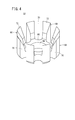
- the packing support member 22 includes a base portion 66 in which a hole 64 is formed, and a plurality of supports that protrude from the outer peripheral portion of the base portion 66 in the thickness direction of the base portion 66 (X1 direction in FIG. 1 and the like). And a piece 68.
- the plurality of support pieces 68 are arranged at intervals in the circumferential direction, and an axial passage 70 is formed between the adjacent support pieces 68.
- a taper portion 72 having a diameter increasing toward the protruding end side is formed on the inner surface of each supporting piece 68 on the protruding end side (tip end side).
- the packing 20 is disposed inside the plurality of support pieces 68 of the packing support member 22, and the locking protrusions 84 provided on the flange 58 a of the bush 58 and the operating rod 18. Held between.
- the plurality of support pieces 68 of the packing support member 22 are positioned closer to the proximal end portion side (X2 direction side) of the operating rod 18 than the distal end portion of the lip portion 62 and support the lip portion 62 from the outside. Further, the packing support member 22 is held between the packing 20 and the locking convex portion 84, and is held between the end surface of the bush 58 and the locking convex portion 84.
- the pilot mechanism section 24 includes a cylinder body 76 having a sliding hole 74 formed therein, a piston 78 slidable in the axial direction within the sliding hole 74 and having a piston packing 77 mounted on the outer peripheral portion thereof, and a piston 78.
- a position detecting magnet 82 is provided.
- the operating rod 18 is coupled to the end of the drive rod 80 on the flow channel body 16 side by, for example, screwing.
- the piston 78, the magnet 82, the drive rod 80, and the actuating rod 18 can be integrally displaced in the axial direction.
- the drive rod 80 and the operating rod 18 constitute a movable body 85.
- the inside of the sliding hole 74 is partitioned by a piston 78 into a first pressure chamber 92a on the piston 78 side and a second pressure chamber 92b on the drive rod 80 side.
- the cylinder body 76 is provided with a pilot port 86 communicating with the first pressure chamber 92a and an atmospheric port 88 communicating with the second pressure chamber 92b and the atmospheric side.
- a filter 90 having air permeability may be disposed in the atmospheric port 88.
- the magnet 82 When the drive rod 80 and the piston 78 are displaced in the axial direction, the magnet 82 is displaced in the axial direction integrally with them. Specifically, a magnet holder 95 is fixed to the drive rod 80 at a position adjacent to the piston 78, and the magnet 82 is held between the magnet holder 95 and the piston 78. The magnet 82 may be attached to the piston 78.
- the piston 78 is urged to the opposite side to the flow path body 16 by a spring 94 as an elastic urging means disposed in the cylinder body 76.
- a spring 94 as an elastic urging means disposed in the cylinder body 76.
- one end (end on the X1 side) of the spring 94 abuts on the rod side cover 96 coupled to the end on the flow path body 16 side of the cylinder body 76, and the other end (on the X2 side) of the spring 94.
- the end portion is in contact with an outward projection 97 provided on the magnet holder 95.
- the piston 78 when a pilot pressure is applied to the first pressure chamber 92a via the pilot port 86, the piston 78 causes the elasticity of the spring 94 under the action of the pilot pressure. 3 is moved in the X1 direction, and stops at the position shown in FIG. At that time, the fluid in the second pressure chamber 92 b is discharged to the atmosphere side through the atmosphere port 88.
- the piston 78 when the pilot pressure is released, the piston 78 is moved in the X2 direction under the action of the elastic force of the spring 94, and returns to the position shown in FIG.
- the detector 25 detects whether or not the movable body 85 is located at a position where the packing 20 is positioned at the valve closed position.
- the detector 25 is attached to the attachment groove 100 provided on the side portion of the cylinder body 76. It is done.
- the detector 25 detects the magnetic field of the magnet 82 when the magnet 82 reaches a predetermined position as the packing 20 reaches the valve closed position (fully closed position) shown in FIG. Output a signal. That is, the detector 25 is configured as a switch that is turned on when the pilot check valve 10 is in the closed state and turned off when the pilot check valve 10 is not in the closed state.
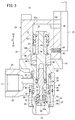
- the lip portion 62 of the packing 20 moves from the valve open position (FIG. 3) toward the valve close position (FIG. 1), as shown in FIG. 2, the lip portion 62 is positioned between the valve close position and the valve open position.
- Contact (seal) with the inner peripheral surface of the flow path body 16 is started.
- the position of the packing 20 shown in FIG. 2 is referred to as a “seal start position”.
- the lip portion 62 moves from the valve open position toward the valve close position, the lip portion 62 is provided on the inner peripheral surface of the flow path body 16 over a predetermined axial range (range from the seal start position to the valve close position). Make sliding contact.
- the seal mechanism by contact between the lip 62 and the inner peripheral surface has an overlap region in the axial direction.
- the detector 25 detects the magnetic field of the magnet 82 and outputs a signal after the packing 20 exceeds the seal start position. That is, when the packing 20 moves from the valve open position toward the valve closed position, the detector 25 does not detect the magnetic field of the magnet 82 and outputs a signal only when the packing 20 reaches the seal start position. Therefore, the pilot check valve 10 is structured such that when the detector 25 outputs a signal, the valve is in a completely closed state (the packing 20 is in the valve closed position). .
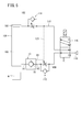
- the fluid pressure circuit 102 includes a cylinder 104 that moves up and down the heavy object W, first and second supply / discharge channels 108 and 110 connected to the head chamber 105 and the rod chamber 106 of the cylinder 104, and a first supply / discharge flow.
- the first speed controller 112 provided on the flow path 108
- the second speed controller 114 provided on the second supply / discharge flow path 110
- the pilot check valve 10 provided on the first supply / discharge flow path 108 With.
- the fluid pressure circuit 102 further includes an electromagnetic switching valve 116 connected to the first and second supply / discharge channels 108 and 110, a pressure supply source 118 connected to the electromagnetic switching valve 116, and a second supply / discharge channel. And a pilot flow path 120 branched from 110 and connected to the pilot port 86 of the pilot check valve 10.
- the first port 12 of the pilot check valve 10 is connected to the electromagnetic switching valve 116 side
- the second port 14 is connected to the rod chamber 106 side of the cylinder 104.
- the working fluid flows into the second body 28 through the side hole 46 provided in the sleeve portion 36 of the second body 28 and deflects the packing 20 radially inward, thereby pass. That is, by pressing the lip portion 62 radially inward under the action of the working fluid, the lip portion 62 is separated from the inner peripheral surface (the reduced diameter portion 50) of the sleeve portion 36, and a gap is formed. , The working fluid flows to the second port 14 side. In this case, since an axial passage 70 (see FIG. 4) is formed in the outer peripheral portion of the packing support member 22, the flow of the working fluid from the first port 12 side to the second port 14 side is hindered. There is nothing to do.
- the working fluid exiting from the second port 14 flows into the rod chamber 106 of the cylinder 104, and the fluid in the head chamber 105 of the cylinder 104 passes through the second supply / discharge channel 110 and the electromagnetic switching valve 116. Then, the cylinder 104 is lifted to the atmosphere side.
- the differential pressure across the packing 20 disappears, so that the lip portion 62 contacts the inner peripheral surface of the sleeve portion 36 again. And adhere closely. In this state, the flow of the working fluid from the second port 14 side to the first port 12 side is blocked by the packing 20 located at the valve closed position, so that the position of the cylinder 104 is maintained. Therefore, the cylinder 104 can be prevented from dropping.
- the electromagnetic switching valve 116 when the electromagnetic switching valve 116 is operated so that the second supply / discharge flow path 110 and the pressure supply source 118 communicate with each other, the working fluid from the pressure supply source 118 passes through the second supply / discharge flow path 110 to the cylinder.
- the head chamber 105 is supplied to the first pressure chamber 92 a of the pilot check valve 10 through the pilot flow path 120.
- the piston 78 receives an acting force based on the pilot pressure, and moves the drive rod 80 connected to the piston 78 and the operating rod 18 connected to the drive rod 80 in the axial direction (X1 direction).
- the packing 20 is moved to the valve open position as shown in FIG. 3, and the first port 12 and the second port 14 communicate with each other. Accordingly, since the flow from the second port 14 to the first port 12 is permitted, the fluid in the rod chamber 106 of the cylinder 104 is moved to the atmosphere side through the first supply / discharge channel 108 and the electromagnetic switching valve 116. As a result, the cylinder 104 moves downward. In this case, the dynamic pressure of the fluid flowing from the second port 14 side to the first port 12 side acts on the lip portion 62 of the packing 20, but the lip portion 62 is supported from the outside by the support piece 68 of the packing support member 22. Therefore, it is possible to prevent the lip 62 from being excessively deformed (warped back).
- the detector 25 outputs a signal as to whether or not the valve is closed (whether the packing 20 is located at the valve closed position). It can be detected by whether or not it is. That is, when the valve is closed, the detector 25 is turned on in response to the magnetic field of the magnet 82 and outputs a signal. Therefore, in the fluid pressure circuit 102, after the cylinder 104 reaches the rising end, the cylinder 104 is dropped by releasing the supply pressure to the first port 12 in a state where a signal is output from the detector 25. Can be prevented.
- the working fluid permits the flow of the working fluid from the first port 12 side to the second port 14 side, while the working fluid from the second port 14 side to the first port 12 side. Therefore, the check valve function can be effectively exhibited even when the pilot pressure is not applied to the pilot check valve 10.
- the lip portion 62 of the packing 20 flows at a position between the valve closed position and the valve open position (seal start position) when the packing 20 moves from the valve open position toward the valve close position. Contact with the inner peripheral surface of the road body 16 is started.
- the lip portion 62 of the packing 20 slidably contacts the inner peripheral surface of the flow path body 16 over a predetermined range in the axial direction when moving from the valve open position toward the valve close position.
- the seal mechanism by contact between the lip portion 62 and the inner peripheral surface has an axial overlap region, and the influence of the detection error and hysteresis of the detector 25 can be eliminated by this overlap region. It is possible to prevent the detector 25 from outputting a signal when the valve is not completely closed. That is, when the detector 25 outputs a signal, it is guaranteed that the valve is in a completely closed state, so that the reliability of the position detection function can be improved.
- the packing check member 10 is provided with a packing support member 22 that surrounds the packing 20 and prevents the lip portion 62 from deforming more than a predetermined amount outward in the radial direction.
- the excessive deformation of the lip portion 62 when the fluid flows to the first port 12 side can be prevented, and the durability of the packing 20 can be improved.
- the packing support member 22 is provided with a passage 70 that allows the flow of the working fluid from the first port 12 side to the lip portion 62, the lip portion 62 is protected without hindering the check valve function of the packing 20.
- the function to perform can be demonstrated suitably.
- the scope of application of the present invention is not limited to the fluid pressure circuit 102 as shown in FIG.
- the pilot check valves 10 are individually connected to the head chamber side and the rod chamber side of the cylinder, and the cylinder position is fixed and held by the check valve function of the two pilot check valves 10 at the time of emergency stop (that is, the operation of the cylinder is controlled). It may be applied to a fluid pressure circuit configured to be constrained.
Landscapes
- Engineering & Computer Science (AREA)
- General Engineering & Computer Science (AREA)
- Mechanical Engineering (AREA)
- Check Valves (AREA)
- Indication Of The Valve Opening Or Closing Status (AREA)
Abstract
パイロットチェック弁(10)は、流路ボディ(16)と、パイロット圧の作用下に軸方向に動作する可動体(85)と、可動体(85)と一体的に弁閉位置と弁開位置との間を変位可能なリップ部(62)を有するパッキン(20)と、可動体(85)の位置を検出する検出器(25)とを備える。パッキン(20)は、弁閉位置において、流路ボディ(16)の第1ポート(12)側から第2ポート(14)側への作動流体の流れを許容するとともに、第2ポート(14)側から第1ポート(12)側への作動流体の流れを阻止し、弁開位置において、第1ポート(12)と第2ポート(14)とを連通させる。
Description
本発明は、作動流体の流れの制御においてパイロット圧を利用するパイロットチェック弁に関する。
従来、流体圧シリンダを駆動する流体圧回路において、作動流体の流れを適切に制御するためにパイロットチェック弁を設けることは公知である(例えば、実開平3-25080号公報を参照)。例えば、流体圧シリンダが昇降用のシリンダとして用いられる流体圧回路では、シリンダのヘッド側圧力室とロッド側圧力室とが切換弁を介して圧力供給源に接続され、ロッド側圧力室と切換弁との間の流路にパイロットチェック弁が配置される。
パイロットチェック弁は、バネによって弁座側に弾性的に付勢されたポペット弁体と、ポペット弁体に対向して軸方向に摺動可能に配置され、パイロット圧印加時にポペット弁体を押圧するパイロットピストンとを備える。パイロットチェック弁には、シリンダのヘッド側圧力室への供給圧の印加に伴って、パイロット圧が印加されるようになっている。
このように構成される流体圧回路において、圧力供給源から切換弁を介してパイロットチェック弁へと作動流体を供給すると、作動流体に基づく圧力作用下にポペット弁体がバネの弾発力に抗して弁座から離間し、これにより作動流体はシリンダのロッド側圧力室へと流入し、シリンダのピストンを押し上げる。そして、ピストンが上昇端に到達すると、ポペット弁体の前後の圧力差がなくなるため、ポペット弁体はバネの弾発力の作用下に弁座に着座する。これにより、圧力供給源からの供給圧を停止しても、ポペット弁体は閉じたままであるため、シリンダの落下を防止することができる。
一方、圧力供給源から切換弁を介してシリンダのヘッド側圧力室へと作動流体を供給すると、パイロット圧によって進出動作するパイロットピストンがポペット弁体を押すことにより、ポペット弁体が弁座から離間する。これにより、シリンダのロッド側圧力室の流体は、パイロットチェック弁を介して切換弁から排出され、これに伴ってシリンダが下降動作する。
ところで、従来のパイロットチェック弁が適用された流体圧回路において、シリンダの落下を防止するためには、弁が閉じた状態になってから供給圧を解除する必要がある。しかしながら、従来のパイロットチェック弁では、弁が閉じたことを検出する機能が設けられていなかった。また、ポペット弁体とパイロットピストンとは分離した構成であり、パイロットピストンの位置とポペット弁体の状態とが常に対応するとは限らないため、仮にパイロットピストンの位置を検出しても、ポペット弁体が着座しているか否かを検出することにはならない。このため、従来のパイロットチェック弁では、弁閉状態であるか否かを適切に検出することができなかった。
本発明はこのような課題を考慮してなされたものであり、弁閉状態であるか否かを適切に検出することができるパイロットチェック弁を提供することを目的とする。
上記の目的を達成するため、本発明は、第1ポート及び第2ポートを有する流路ボディと、少なくとも一部が前記流路ボディ内に摺動可能に配置され、パイロット圧の作用下に軸方向に動作する可動体と、前記可動体に取り付けられ、前記可動体と一体的に弁閉位置と弁開位置との間を変位可能であり、径方向に弾性変形可能な傾斜したリップ部を有し、前記リップ部において前記流路ボディの内周面に摺接可能なパッキンと、前記パッキンを前記弁閉位置に位置させる位置に前記可動体が位置するか否かを検出する検出器と、を備え、前記パッキンは、前記弁閉位置において、前記第1ポート側から前記第2ポート側への作動流体の流れを許容するとともに、前記第2ポート側から前記第1ポート側への前記作動流体の流れを阻止し、前記弁開位置において、前記第1ポートと前記第2ポートとを連通させる、ことを特徴とする。
上記のように構成されたパイロットチェック弁によれば、可動体とパッキンとは一体的に軸方向に変位するため、可動体の位置を検出することで、弁閉状態かどうか(パッキンが弁閉位置に位置しているかどうか)を適切に検出することができる。また、パッキンは、弁閉位置にあるとき、第1ポート側から第2ポート側への作動流体の流れを許容する一方、第2ポート側から第1ポート側への作動流体の流れを阻止するので、パイロット圧が解除されている状態でも、チェック弁機能を有効に発揮することができる。
上記のパイロットチェック弁において、前記パッキンの前記リップ部は、前記弁開位置から前記弁閉位置へ向かって移動する際、前記弁閉位置と前記弁開位置との間に位置するシール開始位置で前記流路ボディの前記内周面との接触を開始することが好ましい。この場合、前記検出器は、前記パッキンが前記弁開位置から前記弁閉位置へ向かって移動する際、前記パッキンが前記シール開始位置を越えてから信号を出力することが好ましい。
この構成により、パッキンのリップ部は、弁開位置から弁閉位置へ向かって移動する際、軸方向の所定範囲にわたって流路ボディの内周面に摺接する。このように、リップ部と内周面との接触によるシール機構は、軸方向のオーバーラップ領域を有しており、このオーバーラップ領域によって検出器の検出誤差やヒステリシスの影響を排除できるので、完全に弁が閉じていない状態で検出器が信号を出力することを防止することができる。すなわち、検出器が信号を出力したときには、必ず弁が完全に閉じている状態にあるため、位置検出機能の信頼性を高めることができる。
上記のパイロットチェック弁において、前記流路ボディの前記内周面は、前記パッキンが前記弁閉位置に位置するときに前記リップ部に押圧接触するシール領域と、前記パッキンが前記弁開位置に位置するときに前記リップ部から離間する非シール領域とを有し、前記非シール領域は、前記シール領域よりも内径が大きいことが好ましい。
この構成により、流路ボディ内でのパッキンの軸方向位置によって、第1ポートと第2ポートとの連通状態と非連通状態を簡便且つ確実に切り換えることができる。
上記のパイロットチェック弁において、前記パッキンを囲み、前記リップ部の径方向外方への所定以上の変形を防止するパッキン支持部材を備えることが好ましい。
この構成により、リップ部の過剰変形を防止し、パッキンの耐久性を向上させることができる。
上記のパイロットチェック弁において、前記パッキン支持部材には、前記第1ポート側から前記リップ部への前記作動流体の流れを許容する通路が設けられることが好ましい。
この構成により、パッキンのチェック弁機能を阻害することなくリップ部を保護する機能を好適に発揮することができる。
本発明のパイロットチェック弁によれば、弁閉状態であるか否かを適切に検出することができる。
以下、本発明に係るパイロットチェック弁について好適な実施形態を挙げ、添付の図面を参照しながら説明する。
図1は、本発明の一実施形態に係るパイロットチェック弁10の弁閉状態の断面図であり、図3は、このパイロットチェック弁10の弁開状態の断面図である。このパイロットチェック弁10は、第1ポート12及び第2ポート14を有する流路ボディ16と、流路ボディ16内に軸方向(矢印X方向)に摺動可能に配置された作動ロッド18と、作動ロッド18に取り付けられたパッキン20と、作動ロッド18に取り付けられたパッキン支持部材22と、流路ボディ16に連結されたパイロット機構部24と、パイロット機構部24に設けられた検出器25とを備える。
流路ボディ16は、作動流体(例えば、空気)の流路を形成する部材である。本実施形態において流路ボディ16は、第1ポート12を有する中空状の第1ボディ26と、第2ポート14を有する中空状の第2ボディ28とを備える。第1ボディ26は、第1ポート12とは反対側に、第2ボディ28が挿入される挿入部30を有し、挿入部30において第2ボディ28を囲む。挿入部30と第2ボディ28との間には、第1ポート12と連通する環状空間32が形成される。
第2ボディ28は、パイロット機構部24と結合する結合部34と、結合部34からパイロット機構部24とは反対方向に突出した中空円筒状のスリーブ部36とを有する。結合部34は、例えば、横断面が六角形状のナットの形態とすることができる。スリーブ部36は、上述した第1ボディ26の挿入部30に挿入される部分である。
スリーブ部36の外周部には、軸方向に間隔を置いて環状のシール部材38、40(例えば、Oリング)が配置される。一方のシール部材38は、スリーブ部36と挿入部30との間に配置される。挿入部30とスリーブ部36との間には中空円筒状のスペーサ部材42が配置され、他方のシール部材40は、スリーブ部36とスペーサ部材42との間に配置される。また、スペーサ部材42と挿入部30との間には、さらに別のシール部材44が配置される。
スリーブ部36において、シール部材38とシール部材40との間には、1以上(図示例では2つ)の側孔46が設けられる。第1ボディ26の中空部と第2ボディ28の中空部とは、側孔46を介して連通する。また、スリーブ部36において、側孔46よりも第2ポート14側、すなわち側孔46と第2ポート14との間の内周面には、拡径部48が設けられる。拡径部48は、スリーブ部36における側孔46と拡径部48との間の部分(以下、「縮径部50」という)の内径よりも大きい。縮径部50は軸方向に沿って内径が一定である。
作動ロッド18は、第2ボディ28のスリーブ部36内で軸方向(X方向)に摺動可能に配置される。具体的には、作動ロッド18の軸方向の中間部には、径方向外方に突出した環状突出部52が設けられ、当該環状突出部52に設けられたシール装着溝54にシール部材56が装着される。当該シール部材56により、第2ボディ28内からパイロット機構部24側への流体の漏出が防止される。
作動ロッド18の先端側(パイロット機構部24とは反対側;X1方向側)の端部には、パッキン20と、パッキン支持部材22とが取り付けられる。具体的には、作動ロッド18の先端部にブッシュ58が固定(図示例では、螺合)されることにより、パッキン20とパッキン支持部材22とが作動ロッド18の先端部に固定されている。従って、作動ロッド18が軸方向に移動する際、パッキン20及びパッキン支持部材22も作動ロッド18と一体的に軸方向に移動する。
パッキン20は、ゴム等(例えば、ブチルゴム、イソプレンゴム、ブタジエンゴム、シリコーンゴム等)の弾性体からなり、全体として中空円筒状であり、具体的には、軸方向に平行な筒状基部60と、この筒状基部60の外周部から傾斜して突出し且つ径方向に弾性変形可能な環状のリップ部62とを有する。
パッキン20は、図1に示す弁閉位置において、第1ポート12側から第2ポート14側への作動流体の流れを許容する一方、第2ポート14側から第1ポート12側への作動流体の流れを阻止する。また、パッキン20は、図3に示す弁開位置において、第1ポート12と第2ポート14とを連通させる。
リップ部62は、作動ロッド18の先端方向(X1方向)に向かって傾斜している。リップ部62は、筒状基部60の外周部において周方向に一周延在する。リップ部62の先端部内面は筒状基部60の外周面に対向して離間している。リップ部62と筒状基部60との間には、X2方向側に凹む環状溝63が形成される。自然状態のリップ部62の外径は、スリーブ部36の縮径部50の内径よりも大きく、且つ拡径部48の内径よりも小さい。
図1に示すように、パッキン20は縮径部50内に位置しているとき、リップ部62は径方向内方に若干だけ弾性圧縮変形した状態(自然状態よりも若干縮径した状態)でスリーブ部36の内周面に全周にわたって接触する。このように、縮径部50は、パッキン20が弁閉位置に位置するときにリップ部62に押圧接触するシール領域を形成する。
一方、図3に示すように、パッキン20が拡径部48内に位置しているとき、リップ部62はスリーブ部36の内周面から離間するため、パッキン20によるシール機能は営まれない。このように、拡径部48は、パッキン20が弁開位置に位置するときにリップ部62から離間する非シール領域を形成する。
パッキン支持部材22は、パッキン20を囲み、リップ部62の径方向外方への所定以上の変形を防止する部材である。パッキン支持部材22は、パッキン20よりも高い剛性をもつように、例えば、硬質樹脂、金属等により構成される。パッキン支持部材22の外径は、スリーブ部36の内周面の内径(具体的には、縮径部50の内径)と略同じか、僅かに小さい。
図4に示すように、パッキン支持部材22は、孔部64が形成された基部66と、基部66の外周部から基部66の厚さ方向(図1等でX1方向)に突出した複数の支持片68とを有する。複数の支持片68は、周方向に間隔を置いて配置されており、隣接する支持片68の間に、軸方向の通路70が形成される。各支持片68の突出端側(先端側)の内面には、突出端側に向かって拡径するテーパ部72が形成される。
図1等に示すように、パッキン20は、パッキン支持部材22の複数の支持片68の内側に配置されるとともに、ブッシュ58のフランジ58aと、作動ロッド18に設けられた係止用凸部84との間に保持される。パッキン支持部材22の複数の支持片68は、リップ部62の先端部よりも作動ロッド18の基端部側(X2方向側)に位置するとともに、リップ部62を外側から支持する。また、パッキン支持部材22は、パッキン20と係止用凸部84との間に保持されるとともに、ブッシュ58の端面と係止用凸部84との間に保持される。
パイロット機構部24は、摺動孔74が形成されたシリンダボディ76と、摺動孔74内で軸方向に摺動可能であり外周部にピストン用パッキン77が装着されたピストン78と、ピストン78が連結された駆動ロッド80と、位置検出用のマグネット82とを有する。この駆動ロッド80の流路ボディ16側の端部に作動ロッド18が例えば螺合により連結される。ピストン78、マグネット82、駆動ロッド80及び作動ロッド18は、一体的に軸方向に変位可能である。駆動ロッド80と作動ロッド18とにより可動体85が構成される。
摺動孔74内は、ピストン78によって、ピストン78側の第1圧力室92aと駆動ロッド80側の第2圧力室92bとに仕切られている。シリンダボディ76には、第1圧力室92aと連通するパイロットポート86と、第2圧力室92bと大気側とを連通する大気ポート88とが設けられる。大気ポート88には、例えば、通気性を有するフィルタ90が配置されるとよい。
マグネット82は、駆動ロッド80及びピストン78が軸方向に変位する際、これらと一体的に軸方向に変位する。具体的には、駆動ロッド80には、ピストン78に隣接する位置にマグネットホルダ95が固定されており、このマグネットホルダ95とピストン78との間にマグネット82が保持される。なお、マグネット82はピストン78に装着されてもよい。
ピストン78は、シリンダボディ76内に配置された弾性付勢手段としてのスプリング94により、流路ボディ16とは反対側に付勢される。図示例では、スプリング94の一端(X1側の端部)は、シリンダボディ76の流路ボディ16側の端部に結合されたロッド側カバー96に当接し、スプリング94の他端(X2側の端部)は、マグネットホルダ95に設けられた外方凸部97に当接する。
上記のように構成されたパイロット機構部24において、パイロットポート86を介して第1圧力室92aにパイロット圧が印加されると、ピストン78は、当該パイロット圧の作用下にスプリング94の弾発力に抗してX1方向へと移動させられ、図3に示す位置で停止する。その際、第2圧力室92b内の流体は、大気ポート88を介して大気側へと排出される。一方、パイロット圧が解除されると、ピストン78は、スプリング94の弾発力の作用下にX2方向へと移動させられ、図1に示す位置に復帰する。
検出器25は、パッキン20を弁閉位置に位置させる位置に可動体85が位置しているか否かを検出するものであり、例えば、シリンダボディ76の側部に設けられた取付溝100に取り付けられる。本実施形態において、検出器25は、パッキン20が図1に示す弁閉位置(全閉位置)に到達することに伴ってマグネット82が所定位置に到達したときに、マグネット82の磁場を検知して信号を出力する。すなわち、検出器25は、パイロットチェック弁10が弁閉状態のときにオンとなり、弁閉状態以外のときにオフとなるスイッチとして構成されている。
パッキン20のリップ部62は、弁開位置(図3)から弁閉位置(図1)へ向かって移動する際、図2に示すように、弁閉位置と弁開位置との間の位置で流路ボディ16の内周面との接触(シール)を開始する。以下、図2に示すパッキン20の位置を「シール開始位置」という。この構成では、リップ部62は、弁開位置から弁閉位置へ向かって移動する際、軸方向の所定範囲(シール開始位置から弁閉位置までの範囲)にわたって流路ボディ16の内周面に摺接する。このように、リップ部62と内周面との接触によるシール機構は、軸方向のオーバーラップ領域を有する。
パッキン20が弁開位置から弁閉位置へ向かって移動する際、検出器25は、パッキン20がシール開始位置を越えてから、マグネット82の磁場を検出して、信号を出力する。すなわち、パッキン20が弁開位置から弁閉位置へ向かって移動する際、パッキン20がシール開始位置に到達しただけでは検出器25はマグネット82の磁場を検出せず、信号を出力しない。従って、このパイロットチェック弁10では、検出器25が信号を出力しているときは、弁が完全に閉じた状態になっている(パッキン20が弁閉位置にある)という構造が構築されている。
上記のように構成されるパイロットチェック弁10は、例えば、図5に示すような流体圧回路102に適用すると、シリンダ104の落下を防止することができる。
この流体圧回路102は、重量物Wを昇降させるシリンダ104と、シリンダ104のヘッド室105とロッド室106にそれぞれ接続された第1及び第2給排流路108、110と、第1給排流路108上に設けられた第1スピードコントローラ112と、第2給排流路110上に設けられた第2スピードコントローラ114と、第1給排流路108上に設けられたパイロットチェック弁10とを備える。
流体圧回路102は、さらに、第1及び第2給排流路108、110に接続された電磁切換弁116と、電磁切換弁116に接続された圧力供給源118と、第2給排流路110から分岐してパイロットチェック弁10のパイロットポート86に接続されたパイロット流路120とを備える。この場合、パイロットチェック弁10の第1ポート12は電磁切換弁116側に接続され、第2ポート14はシリンダ104のロッド室106側に接続される。
このように構成される流体圧回路102において、図5に示すように第1給排流路108と圧力供給源118とを連通するように電磁切換弁116を作動させると、圧力供給源118からの作動流体はパイロットチェック弁10の第1ポート12を介して流路ボディ16内に流入する。この場合、パイロットチェック弁10にはパイロット圧が印加されていないため、図1のように、スプリング94の弾発力の作用下に、パッキン20は弁閉位置に位置している。
一方、作動流体は、第2ボディ28のスリーブ部36に設けられた側孔46を介して第2ボディ28内へと流入するとともに、パッキン20を径方向内方に撓ませて、パッキン20を通過する。すなわち、作動流体の作用下にリップ部62を径方向内方に押圧することにより、リップ部62がスリーブ部36の内周面(縮径部50)から離間して隙間が形成され、当該隙間を介して作動流体が第2ポート14側へと流れる。この場合、パッキン支持部材22の外周部には、軸方向の通路70(図4参照)が形成されているため、第1ポート12側から第2ポート14側への作動流体の流れが阻害されることがない。
そして、図5において、第2ポート14から出た作動流体は、シリンダ104のロッド室106へと流入し、シリンダ104のヘッド室105の流体は第2給排流路110及び電磁切換弁116を介して大気側へと排出され、これに伴ってシリンダ104は上昇動作する。シリンダ104が上昇端に到達すると、パッキン20の前後差圧(第1ポート12側と第2ポート14側との差圧)がなくなるため、リップ部62はスリーブ部36の内周面に再び接触し密着する。この状態では、弁閉位置に位置するパッキン20により、第2ポート14側から第1ポート12側への作動流体の流れが阻止されるため、シリンダ104の位置は保持される。従って、シリンダ104の落下を防止することができる。
一方、第2給排流路110と圧力供給源118とを連通するように電磁切換弁116を作動させると、圧力供給源118からの作動流体は、第2給排流路110を介してシリンダ104のヘッド室105に供給されるとともに、パイロット流路120を介して、パイロットチェック弁10の第1圧力室92aに導入される。これにより、ピストン78がパイロット圧に基づく作用力を受けて、ピストン78に連結された駆動ロッド80と、この駆動ロッド80に連結された作動ロッド18を軸方向(X1方向)に移動させる。
この作動ロッド18の移動に伴って、図3に示すようにパッキン20は弁開位置に移動させられ、第1ポート12と第2ポート14とが連通するに至る。従って、第2ポート14から第1ポート12への流れが許容された状態となるため、シリンダ104のロッド室106の流体が第1給排流路108及び電磁切換弁116を介して大気側に排出され、これに伴ってシリンダ104は下降動作する。この場合、第2ポート14側から第1ポート12側へ流れる流体の動圧がパッキン20のリップ部62に作用するが、リップ部62はパッキン支持部材22の支持片68によって外側から支持されているため、リップ部62に過剰変形(反り返り)が生じることが防止される。
以上説明したように、本実施形態に係るパイロットチェック弁10によれば、弁閉状態となっているかどうか(パッキン20が弁閉位置に位置しているかどうか)を検出器25が信号を出力しているか否かにより検出することができる。すなわち、弁閉状態になっているときは、検出器25がマグネット82の磁場に反応してオンとなり信号を出力する。従って、流体圧回路102では、シリンダ104が上昇端に到達した後、検出器25から信号が出力されている状態で、第1ポート12への供給圧を解除することにより、シリンダ104の落下を防止することができる。
また、パッキン20は、弁閉位置にあるとき、第1ポート12側から第2ポート14側への作動流体の流れを許容する一方、第2ポート14側から第1ポート12側への作動流体の流れを阻止するので、パイロットチェック弁10に対してパイロット圧が印加されていない状態でも、チェック弁機能を有効に発揮することができる。
本実施形態の場合、パッキン20のリップ部62は、パッキン20が弁開位置から弁閉位置へ向かって移動する際、弁閉位置と弁開位置との間の位置(シール開始位置)で流路ボディ16の内周面との接触を開始する。この構成により、パッキン20のリップ部62は、弁開位置から弁閉位置へ向かって移動する際、軸方向の所定範囲にわたって流路ボディ16の内周面に摺接する。
このように、リップ部62と内周面との接触によるシール機構は、軸方向のオーバーラップ領域を有しており、このオーバーラップ領域によって検出器25の検出誤差やヒステリシスの影響を排除できるので、完全に弁が閉じていない状態で検出器25が信号を出力することを防止することができる。すなわち、検出器25が信号を出力しているときは、必ず弁が完全に閉じている状態であることが保障されるため、位置検出機能の信頼性を高めることができる。
また、本実施形態に係るパイロットチェック弁10の場合、パッキン20を囲み、リップ部62の径方向外方への所定以上の変形を防止するパッキン支持部材22を備えるので、第2ポート14側から第1ポート12側へ流体が流れる際のリップ部62の過剰変形を防止し、パッキン20の耐久性を向上させることができる。
しかも、パッキン支持部材22には、第1ポート12側からリップ部62への作動流体の流れを許容する通路70が設けられるので、パッキン20のチェック弁機能を阻害することなくリップ部62を保護する機能を好適に発揮することができる。
なお、本発明の適用範囲は、図5に示したような流体圧回路102に限られない。例えば、シリンダのヘッド室側とロッド室側とに個別にパイロットチェック弁10が接続され、非常停止時には2つのパイロットチェック弁10のチェック弁機能によりシリンダの位置を固定保持する(すなわちシリンダの動作を拘束する)ように構成された流体圧回路に適用されてもよい。
上記において、本発明について好適な実施形態を挙げて説明したが、本発明は前記実施形態に限定されるものではなく、本発明の要旨を逸脱しない範囲において、種々の改変が可能なことは言うまでもない。
Claims (6)
- 第1ポート(12)及び第2ポート(14)を有する流路ボディ(16)と、
少なくとも一部が前記流路ボディ(16)内に摺動可能に配置され、パイロット圧の作用下に軸方向に動作する可動体(85)と、
前記可動体(85)に取り付けられ、前記可動体(85)と一体的に弁閉位置と弁開位置との間を変位可能であり、径方向に弾性変形可能な傾斜したリップ部(62)を有し、前記リップ部(62)において前記流路ボディ(16)の内周面に摺接可能なパッキン(20)と、
前記パッキン(20)を前記弁閉位置に位置させる位置に前記可動体(85)が位置するか否かを検出する検出器(25)と、を備え、
前記パッキン(20)は、前記弁閉位置において、前記第1ポート(12)側から前記第2ポート(14)側への作動流体の流れを許容するとともに、前記第2ポート(14)側から前記第1ポート(12)側への前記作動流体の流れを阻止し、前記弁開位置において、前記第1ポート(12)と前記第2ポート(14)とを連通させる、
ことを特徴とするパイロットチェック弁(10)。 - 請求項1記載のパイロットチェック弁(10)において、
前記パッキン(20)の前記リップ部(62)は、前記弁開位置から前記弁閉位置へ向かって移動する際、前記弁閉位置と前記弁開位置との間に位置するシール開始位置で前記流路ボディ(16)の前記内周面との接触を開始する、
ことを特徴とするパイロットチェック弁(10)。 - 請求項2記載のパイロットチェック弁(10)において、
前記検出器(25)は、前記パッキン(20)が前記弁開位置から前記弁閉位置へ向かって移動する際、前記パッキン(20)が前記シール開始位置を越えてから信号を出力する、
ことを特徴とするパイロットチェック弁(10)。 - 請求項1記載のパイロットチェック弁(10)において、
前記流路ボディ(16)の前記内周面は、前記パッキン(20)が前記弁閉位置に位置するときに前記リップ部(62)に押圧接触するシール領域と、前記パッキン(20)が前記弁開位置に位置するときに前記リップ部(62)から離間する非シール領域とを有し、
前記非シール領域は、前記シール領域よりも内径が大きい、
ことを特徴とするパイロットチェック弁(10)。 - 請求項1記載のパイロットチェック弁(10)において、
前記パッキン(20)を囲み、前記リップ部(62)の径方向外方への所定以上の変形を防止するパッキン支持部材(22)を備える、
ことを特徴とするパイロットチェック弁(10)。 - 請求項5記載のパイロットチェック弁(10)において、
前記パッキン支持部材(22)には、前記第1ポート(12)側から前記リップ部(62)への前記作動流体の流れを許容する通路(70)が設けられる、
ことを特徴とするパイロットチェック弁(10)。
Priority Applications (4)
| Application Number | Priority Date | Filing Date | Title |
|---|---|---|---|
| US15/515,881 US10458560B2 (en) | 2014-10-10 | 2015-07-08 | Pilot check valve |
| ES15848823T ES2727434T3 (es) | 2014-10-10 | 2015-07-08 | Válvula de retención piloto |
| EP15848823.9A EP3205915B1 (en) | 2014-10-10 | 2015-07-08 | Pilot check valve |
| CN201580054629.7A CN106795980B (zh) | 2014-10-10 | 2015-07-08 | 导向止回阀 |
Applications Claiming Priority (2)
| Application Number | Priority Date | Filing Date | Title |
|---|---|---|---|
| JP2014209252A JP6222573B2 (ja) | 2014-10-10 | 2014-10-10 | パイロットチェック弁 |
| JP2014-209252 | 2014-10-10 |
Publications (1)
| Publication Number | Publication Date |
|---|---|
| WO2016056280A1 true WO2016056280A1 (ja) | 2016-04-14 |
Family
ID=55652905
Family Applications (1)
| Application Number | Title | Priority Date | Filing Date |
|---|---|---|---|
| PCT/JP2015/069601 Ceased WO2016056280A1 (ja) | 2014-10-10 | 2015-07-08 | パイロットチェック弁 |
Country Status (6)
| Country | Link |
|---|---|
| US (1) | US10458560B2 (ja) |
| EP (1) | EP3205915B1 (ja) |
| JP (1) | JP6222573B2 (ja) |
| CN (1) | CN106795980B (ja) |
| ES (1) | ES2727434T3 (ja) |
| WO (1) | WO2016056280A1 (ja) |
Cited By (1)
| Publication number | Priority date | Publication date | Assignee | Title |
|---|---|---|---|---|
| EP3428458A3 (en) * | 2017-06-23 | 2019-06-12 | Deere & Company | System and method for hydraulic actuator lock valve |
Families Citing this family (9)
| Publication number | Priority date | Publication date | Assignee | Title |
|---|---|---|---|---|
| CN109720327B (zh) * | 2017-10-20 | 2022-08-02 | 株式会社万都 | 止回阀 |
| EP3717133A4 (en) * | 2017-11-27 | 2021-08-25 | Zentech, Inc. | SELF-CLOSING EJECTION VALVE |
| US11719358B2 (en) | 2017-12-30 | 2023-08-08 | Itt Manufacturing Enterprises Llc | Switch for diaphragm valve actuator |
| JP6960585B2 (ja) * | 2018-12-03 | 2021-11-05 | Smc株式会社 | 流量コントローラ及びそれを備えた駆動装置 |
| WO2020157891A1 (ja) * | 2019-01-31 | 2020-08-06 | サントリーホールディングス株式会社 | ビールテイスト飲料 |
| GB201904245D0 (en) * | 2019-03-27 | 2019-05-08 | Lontra Ltd | Check Valve |
| JP7548497B2 (ja) * | 2020-05-19 | 2024-09-10 | 丸一株式会社 | 弁部材 |
| JP7058790B1 (ja) * | 2021-07-19 | 2022-04-22 | 旭有機材株式会社 | タイミング調整弁及びこれを備えるサックバックバルブ |
| JP7722130B2 (ja) * | 2021-10-21 | 2025-08-13 | Smc株式会社 | パイロットチェック弁 |
Citations (3)
| Publication number | Priority date | Publication date | Assignee | Title |
|---|---|---|---|---|
| JPS57129970A (en) * | 1980-12-24 | 1982-08-12 | Esuemubuee Shiyunaidaa Unto Bu | Releasable check valve |
| JPH0425077U (ja) * | 1990-06-26 | 1992-02-28 | ||
| US20040144938A1 (en) * | 2002-10-17 | 2004-07-29 | Frank Akselberg | Pressure compensated pilot operated check valve |
Family Cites Families (10)
| Publication number | Priority date | Publication date | Assignee | Title |
|---|---|---|---|---|
| US3357215A (en) * | 1964-12-07 | 1967-12-12 | Trico Products Corp | Vehicle door locking system |
| US4545287A (en) * | 1982-10-22 | 1985-10-08 | The Cessna Aircraft Company | Metered lockout valve |
| FR2573136B1 (fr) * | 1984-11-15 | 1989-03-31 | Schlumberger Cie Dowell | Procede d'observation des caracteristiques de pompage sur une pompe a deplacement positif et pompe permettant de mettre en oeuvre ce procede. |
| JPH0325080A (ja) * | 1989-06-20 | 1991-02-01 | Hino Motors Ltd | 後軸操舵装置 |
| JPH0620939Y2 (ja) | 1989-07-21 | 1994-06-01 | 豊興工業株式会社 | パイロット操作逆止め弁 |
| CN2539026Y (zh) * | 2002-03-26 | 2003-03-05 | 广州家之宝发展有限公司 | 燃气管道用的安全阀 |
| JP4639159B2 (ja) * | 2006-03-08 | 2011-02-23 | 株式会社熊谷鉄工所 | チェッキ弁 |
| US8608005B2 (en) * | 2009-04-30 | 2013-12-17 | Johnson Controls Autobatterie Gmbh & Co. Kgaa | Valve plug |
| JP2013104518A (ja) * | 2011-11-16 | 2013-05-30 | Kawasaki Heavy Ind Ltd | クッションバルブ装置、及びそれを備えるマルチクッションバルブユニット |
| WO2013116488A1 (en) * | 2012-02-03 | 2013-08-08 | S.P.M. Flow Control, Inc. | Pump assembly including fluid cylinder and tapered valve seats |
-
2014
- 2014-10-10 JP JP2014209252A patent/JP6222573B2/ja active Active
-
2015
- 2015-07-08 US US15/515,881 patent/US10458560B2/en active Active
- 2015-07-08 CN CN201580054629.7A patent/CN106795980B/zh not_active Expired - Fee Related
- 2015-07-08 EP EP15848823.9A patent/EP3205915B1/en active Active
- 2015-07-08 WO PCT/JP2015/069601 patent/WO2016056280A1/ja not_active Ceased
- 2015-07-08 ES ES15848823T patent/ES2727434T3/es active Active
Patent Citations (3)
| Publication number | Priority date | Publication date | Assignee | Title |
|---|---|---|---|---|
| JPS57129970A (en) * | 1980-12-24 | 1982-08-12 | Esuemubuee Shiyunaidaa Unto Bu | Releasable check valve |
| JPH0425077U (ja) * | 1990-06-26 | 1992-02-28 | ||
| US20040144938A1 (en) * | 2002-10-17 | 2004-07-29 | Frank Akselberg | Pressure compensated pilot operated check valve |
Cited By (2)
| Publication number | Priority date | Publication date | Assignee | Title |
|---|---|---|---|---|
| EP3428458A3 (en) * | 2017-06-23 | 2019-06-12 | Deere & Company | System and method for hydraulic actuator lock valve |
| US10487474B2 (en) | 2017-06-23 | 2019-11-26 | Deere & Company | System and method for hydraulic actuator lock valve |
Also Published As
| Publication number | Publication date |
|---|---|
| ES2727434T3 (es) | 2019-10-16 |
| CN106795980A (zh) | 2017-05-31 |
| CN106795980B (zh) | 2019-04-09 |
| US10458560B2 (en) | 2019-10-29 |
| US20170307093A1 (en) | 2017-10-26 |
| EP3205915A4 (en) | 2018-06-20 |
| JP2016080007A (ja) | 2016-05-16 |
| JP6222573B2 (ja) | 2017-11-01 |
| EP3205915A1 (en) | 2017-08-16 |
| EP3205915B1 (en) | 2019-03-13 |
Similar Documents
| Publication | Publication Date | Title |
|---|---|---|
| JP6222573B2 (ja) | パイロットチェック弁 | |
| JP4035728B2 (ja) | サックバックバルブ | |
| KR101479323B1 (ko) | 2방 밸브 | |
| JP4310532B2 (ja) | 流量調整弁 | |
| EP3569921A1 (en) | Poppet type pneumatic valve for inflation system | |
| JP5456485B2 (ja) | スライド・バルブ | |
| EP3614025B1 (en) | Two-way valve | |
| CN111094817B (zh) | 带有顺序阀的缸体装置 | |
| US7066202B2 (en) | Indicator-equipped flow regulating valve | |
| KR102394011B1 (ko) | 임의의 유형의 매체 유동을 제어하기 위한 밸브 장치 | |
| JP2008222214A5 (ja) | ||
| US20080116741A1 (en) | Ventilation Device for a Combined Spring Accumulator and Operating Brake Cylinder | |
| JP4464242B2 (ja) | モジュレータ | |
| JP6932240B2 (ja) | 耐汚染性ポペットバルブ | |
| KR20170074350A (ko) | 피스톤 밸브 | |
| TWI678488B (zh) | 流路單元及切換閥 | |
| JP6796291B2 (ja) | エアシリンダ | |
| JP4860506B2 (ja) | 制御弁 | |
| US10240684B2 (en) | Valve assembly having a manual override unit | |
| GB1580246A (en) | Fluid valve | |
| JP6567916B2 (ja) | カップリング装置 | |
| WO2019044115A1 (ja) | マスタシリンダ | |
| CN111684187B (zh) | 流动路径的转换阀 | |
| US20180094653A1 (en) | Position Dependent Valve Device for Control Cylinder | |
| JPS624587B2 (ja) |
Legal Events
| Date | Code | Title | Description |
|---|---|---|---|
| 121 | Ep: the epo has been informed by wipo that ep was designated in this application |
Ref document number: 15848823 Country of ref document: EP Kind code of ref document: A1 |
|
| REEP | Request for entry into the european phase |
Ref document number: 2015848823 Country of ref document: EP |
|
| WWE | Wipo information: entry into national phase |
Ref document number: 2015848823 Country of ref document: EP |
|
| WWE | Wipo information: entry into national phase |
Ref document number: 15515881 Country of ref document: US |
|
| NENP | Non-entry into the national phase |
Ref country code: DE |