WO2016059833A1 - 銅-ニッケル合金電気めっき装置 - Google Patents
銅-ニッケル合金電気めっき装置 Download PDFInfo
- Publication number
- WO2016059833A1 WO2016059833A1 PCT/JP2015/068332 JP2015068332W WO2016059833A1 WO 2016059833 A1 WO2016059833 A1 WO 2016059833A1 JP 2015068332 W JP2015068332 W JP 2015068332W WO 2016059833 A1 WO2016059833 A1 WO 2016059833A1
- Authority
- WO
- WIPO (PCT)
- Prior art keywords
- chamber
- cathode chamber
- oxidation
- anode chamber
- reduction potential
- Prior art date
- Legal status (The legal status is an assumption and is not a legal conclusion. Google has not performed a legal analysis and makes no representation as to the accuracy of the status listed.)
- Ceased
Links
Images


Classifications
-
- C—CHEMISTRY; METALLURGY
- C25—ELECTROLYTIC OR ELECTROPHORETIC PROCESSES; APPARATUS THEREFOR
- C25D—PROCESSES FOR THE ELECTROLYTIC OR ELECTROPHORETIC PRODUCTION OF COATINGS; ELECTROFORMING; APPARATUS THEREFOR
- C25D21/00—Processes for servicing or operating cells for electrolytic coating
- C25D21/12—Process control or regulation
- C25D21/14—Controlled addition of electrolyte components
-
- C—CHEMISTRY; METALLURGY
- C25—ELECTROLYTIC OR ELECTROPHORETIC PROCESSES; APPARATUS THEREFOR
- C25D—PROCESSES FOR THE ELECTROLYTIC OR ELECTROPHORETIC PRODUCTION OF COATINGS; ELECTROFORMING; APPARATUS THEREFOR
- C25D17/00—Constructional parts, or assemblies thereof, of cells for electrolytic coating
- C25D17/02—Tanks; Installations therefor
-
- C—CHEMISTRY; METALLURGY
- C22—METALLURGY; FERROUS OR NON-FERROUS ALLOYS; TREATMENT OF ALLOYS OR NON-FERROUS METALS
- C22C—ALLOYS
- C22C19/00—Alloys based on nickel or cobalt
- C22C19/002—Alloys based on nickel or cobalt with copper as the next major constituent
-
- C—CHEMISTRY; METALLURGY
- C22—METALLURGY; FERROUS OR NON-FERROUS ALLOYS; TREATMENT OF ALLOYS OR NON-FERROUS METALS
- C22C—ALLOYS
- C22C19/00—Alloys based on nickel or cobalt
- C22C19/03—Alloys based on nickel or cobalt based on nickel
-
- C—CHEMISTRY; METALLURGY
- C22—METALLURGY; FERROUS OR NON-FERROUS ALLOYS; TREATMENT OF ALLOYS OR NON-FERROUS METALS
- C22C—ALLOYS
- C22C9/00—Alloys based on copper
- C22C9/06—Alloys based on copper with nickel or cobalt as the next major constituent
-
- C—CHEMISTRY; METALLURGY
- C25—ELECTROLYTIC OR ELECTROPHORETIC PROCESSES; APPARATUS THEREFOR
- C25D—PROCESSES FOR THE ELECTROLYTIC OR ELECTROPHORETIC PRODUCTION OF COATINGS; ELECTROFORMING; APPARATUS THEREFOR
- C25D17/00—Constructional parts, or assemblies thereof, of cells for electrolytic coating
- C25D17/002—Cell separation, e.g. membranes, diaphragms
-
- C—CHEMISTRY; METALLURGY
- C25—ELECTROLYTIC OR ELECTROPHORETIC PROCESSES; APPARATUS THEREFOR
- C25D—PROCESSES FOR THE ELECTROLYTIC OR ELECTROPHORETIC PRODUCTION OF COATINGS; ELECTROFORMING; APPARATUS THEREFOR
- C25D17/00—Constructional parts, or assemblies thereof, of cells for electrolytic coating
- C25D17/008—Current shielding devices
-
- C—CHEMISTRY; METALLURGY
- C25—ELECTROLYTIC OR ELECTROPHORETIC PROCESSES; APPARATUS THEREFOR
- C25D—PROCESSES FOR THE ELECTROLYTIC OR ELECTROPHORETIC PRODUCTION OF COATINGS; ELECTROFORMING; APPARATUS THEREFOR
- C25D21/00—Processes for servicing or operating cells for electrolytic coating
- C25D21/06—Filtering particles other than ions
-
- C—CHEMISTRY; METALLURGY
- C25—ELECTROLYTIC OR ELECTROPHORETIC PROCESSES; APPARATUS THEREFOR
- C25D—PROCESSES FOR THE ELECTROLYTIC OR ELECTROPHORETIC PRODUCTION OF COATINGS; ELECTROFORMING; APPARATUS THEREFOR
- C25D21/00—Processes for servicing or operating cells for electrolytic coating
- C25D21/10—Agitating of electrolytes; Moving of racks
-
- C—CHEMISTRY; METALLURGY
- C25—ELECTROLYTIC OR ELECTROPHORETIC PROCESSES; APPARATUS THEREFOR
- C25D—PROCESSES FOR THE ELECTROLYTIC OR ELECTROPHORETIC PRODUCTION OF COATINGS; ELECTROFORMING; APPARATUS THEREFOR
- C25D21/00—Processes for servicing or operating cells for electrolytic coating
- C25D21/12—Process control or regulation
-
- C—CHEMISTRY; METALLURGY
- C25—ELECTROLYTIC OR ELECTROPHORETIC PROCESSES; APPARATUS THEREFOR
- C25D—PROCESSES FOR THE ELECTROLYTIC OR ELECTROPHORETIC PRODUCTION OF COATINGS; ELECTROFORMING; APPARATUS THEREFOR
- C25D3/00—Electroplating: Baths therefor
- C25D3/02—Electroplating: Baths therefor from solutions
- C25D3/56—Electroplating: Baths therefor from solutions of alloys
- C25D3/562—Electroplating: Baths therefor from solutions of alloys containing more than 50% by weight of iron or nickel or cobalt
-
- C—CHEMISTRY; METALLURGY
- C25—ELECTROLYTIC OR ELECTROPHORETIC PROCESSES; APPARATUS THEREFOR
- C25D—PROCESSES FOR THE ELECTROLYTIC OR ELECTROPHORETIC PRODUCTION OF COATINGS; ELECTROFORMING; APPARATUS THEREFOR
- C25D3/00—Electroplating: Baths therefor
- C25D3/02—Electroplating: Baths therefor from solutions
- C25D3/56—Electroplating: Baths therefor from solutions of alloys
- C25D3/58—Electroplating: Baths therefor from solutions of alloys containing more than 50% by weight of copper
-
- C—CHEMISTRY; METALLURGY
- C25—ELECTROLYTIC OR ELECTROPHORETIC PROCESSES; APPARATUS THEREFOR
- C25D—PROCESSES FOR THE ELECTROLYTIC OR ELECTROPHORETIC PRODUCTION OF COATINGS; ELECTROFORMING; APPARATUS THEREFOR
- C25D5/00—Electroplating characterised by the process; Pretreatment or after-treatment of workpieces
- C25D5/08—Electroplating with moving electrolyte e.g. jet electroplating
-
- C—CHEMISTRY; METALLURGY
- C25—ELECTROLYTIC OR ELECTROPHORETIC PROCESSES; APPARATUS THEREFOR
- C25D—PROCESSES FOR THE ELECTROLYTIC OR ELECTROPHORETIC PRODUCTION OF COATINGS; ELECTROFORMING; APPARATUS THEREFOR
- C25D5/00—Electroplating characterised by the process; Pretreatment or after-treatment of workpieces
- C25D5/60—Electroplating characterised by the structure or texture of the layers
- C25D5/605—Surface topography of the layers, e.g. rough, dendritic or nodular layers
- C25D5/611—Smooth layers
-
- C—CHEMISTRY; METALLURGY
- C25—ELECTROLYTIC OR ELECTROPHORETIC PROCESSES; APPARATUS THEREFOR
- C25D—PROCESSES FOR THE ELECTROLYTIC OR ELECTROPHORETIC PRODUCTION OF COATINGS; ELECTROFORMING; APPARATUS THEREFOR
- C25D5/00—Electroplating characterised by the process; Pretreatment or after-treatment of workpieces
- C25D5/627—Electroplating characterised by the visual appearance of the layers, e.g. colour, brightness or mat appearance
Definitions
- the present invention relates to a plating apparatus, and more particularly to a copper-nickel alloy electroplating apparatus.
- copper-nickel alloys exhibit excellent properties in corrosion resistance, spreadability, workability, and high temperature characteristics by changing the ratio of copper and nickel, and also have electrical resistivity, thermal resistance coefficient, thermoelectric power, thermal It also has a characteristic property in the expansion coefficient. Therefore, researches for obtaining such characteristics of the copper-nickel alloy by electroplating have been conventionally performed.
- a copper-nickel alloy electroplating bath that has been tried, many baths such as a cyan bath, a citric acid bath, an acetic acid bath, a tartaric acid bath, a thiosulfuric acid bath, an ammonia bath, and a pyrophosphoric acid bath have been studied. It has not been put to practical use.
- the reason why copper-nickel alloy electroplating was not put to practical use (1) The deposition potential of copper and nickel is about 0.6 V apart, and copper is preferentially deposited. (2) The plating bath is unstable and insoluble compounds such as metal hydroxide are generated. (3) The plating composition fluctuates by energization, and a film having a uniform composition cannot be stably obtained. (4) The liquid life is short, Etc.
- the present invention provides a copper-nickel alloy electroplating apparatus, a cathode chamber in which an object to be plated is disposed, an anode chamber, and an anode disposed in the anode chamber.
- An electrically conductive diaphragm disposed so as to separate the cathode chamber and the anode chamber, a cathode chamber oxidation-reduction potential adjusting tank for adjusting the oxidation-reduction potential of the plating solution in the cathode chamber, and a plating solution in the anode chamber It is characterized by having an anode chamber oxidation / reduction potential adjustment tank for adjusting the oxidation / reduction potential, and a power supply unit for passing a current between the object to be plated and the anode.
- the oxidation reduction potential of the cathode chamber and the anode chamber is adjusted by the cathode chamber oxidation reduction potential adjustment tank and the anode chamber oxidation reduction potential adjustment tank.
- a plating film having a uniform composition can be obtained while depositing nickel at an arbitrary alloy ratio.
- the bath state can be maintained stably, and a good copper-nickel alloy electroplating film can be obtained even if the plating bath (plating solution) is used continuously for a long period of time. Can do.
- a cathode chamber circulation device for circulating the plating solution in the cathode chamber and the cathode chamber oxidation-reduction potential adjustment tank, and an anode for circulating the plating solution in the anode chamber and the anode chamber oxidation-reduction potential adjustment vessel.
- a chamber circulation device for circulating the plating solution in the cathode chamber and the cathode chamber oxidation-reduction potential adjustment tank, and an anode for circulating the plating solution in the anode chamber and the anode chamber oxidation-reduction potential adjustment vessel.
- the plating solution for the cathode chamber and the cathode chamber oxidation-reduction potential adjustment tank and the plating solution for the anode chamber and anode chamber oxidation-reduction potential adjustment vessel are circulated by the circulation device.
- the plating solutions on the side and anode side can be maintained uniformly, and a uniform plating film can be obtained.
- the diaphragm is preferably a polyester, polypropylene, Kanekalon, Saran or PTFE cloth, a neutral diaphragm, or an ion exchange membrane. According to the present invention configured as described above, the diaphragm can be configured at low cost.
- the cathode chamber circulation device includes a cathode chamber weir section that causes the plating solution in the cathode chamber to overflow into the cathode chamber oxidation-reduction potential adjustment vessel, and the plating solution in the cathode chamber oxidation-reduction potential adjustment vessel in the cathode chamber.
- a cathode chamber transfer device for transferring, and a cathode chamber filtration device for filtering the plating solution transferred by the cathode chamber transfer device, and the anode chamber circulation device serves as an anode for the plating solution in the anode chamber oxidation-reduction potential adjustment tank.
- An anode chamber weir that overflows into the chamber, an anode chamber transfer device that transfers the plating solution in the anode chamber to the anode chamber oxidation-reduction potential adjustment tank, and an anode chamber filtration device that filters the plating solution transferred by the anode chamber transfer device And.
- the oxidation-reduction potential in the cathode chamber and the anode chamber can be easily maintained at an appropriate value by using the cathode chamber oxidation-reduction potential adjustment vessel and the anode chamber oxidation-reduction potential adjustment vessel. Can do.
- the cathode chamber circulation device includes a cathode chamber first transfer device that transfers the plating solution in the cathode chamber to the cathode chamber oxidation-reduction potential adjustment vessel, and the plating solution in the cathode chamber oxidation-reduction potential adjustment vessel as the cathode.
- a cathode chamber second transfer device for transferring to the chamber, and a cathode chamber filtration device for filtering the plating solution circulated between the cathode chamber and the cathode chamber oxidation-reduction potential adjustment tank.
- An anode chamber first transfer device for transferring the plating solution in the oxidation-reduction potential adjustment tank to the anode chamber
- an anode chamber second transfer device for transferring the plating solution in the anode chamber to the anode chamber oxidation-reduction potential adjustment vessel
- An anode chamber filtration device for filtering the plating solution circulated between the anode chamber oxidation-reduction potential adjustment tanks.
- the oxidation-reduction potential in the cathode chamber and the anode chamber can be easily maintained at an appropriate value by using the cathode chamber oxidation-reduction potential adjustment vessel and the anode chamber oxidation-reduction potential adjustment vessel. Can do.
- the plating solution is circulated between the cathode chamber and the cathode chamber oxidation-reduction potential adjustment tank, and between the anode chamber and the anode chamber oxidation-reduction potential adjustment tank.
- the tank and the anode chamber oxidation-reduction potential adjustment tank can be arranged at arbitrary positions.
- a cathode chamber potential measuring device for measuring the oxidation-reduction potential of the plating solution in the cathode chamber, an anode chamber potential measuring device for measuring the oxidation-reduction potential of the plating solution in the anode chamber, and the cathode chamber oxidation
- Cathode chamber adjusting agent adding device for adding redox potential adjusting agent to reduction potential adjusting vessel, anode chamber adjusting agent adding device for adding redox potential adjusting agent to anode chamber redox potential adjusting vessel, and cathode chamber potential measuring device
- a control unit for controlling the cathode chamber adjusting agent adding device and the anode chamber adjusting agent adding device based on the redox potential measured by the above and the redox potential measured by the anode chamber potential measuring device.
- the oxidation-reduction potential in the cathode chamber and the anode chamber can be accurately maintained at an appropriate value.
- the present invention preferably, it further has a cathode chamber, an anode chamber, a cathode chamber oxidation-reduction potential adjustment tank, and a copper-nickel alloy electroplating solution accommodated in the anode chamber oxidation-reduction potential adjustment tank.
- the alloy electroplating solution contains (a) a copper salt and a nickel salt, (b) a metal complexing agent, (c) a conductivity-imparting salt, and (d) a sulfur-containing organic compound. According to the present invention configured as described above, a good copper-nickel alloy electroplating film can be obtained.
- a plating film having a uniform composition of copper and nickel can be stably formed on an object to be plated, and a plating bath can be used for a long time.
- FIG. 1 is a cross-sectional view of a copper-nickel alloy electroplating apparatus according to a first embodiment of the present invention. It is sectional drawing of the copper-nickel alloy electroplating apparatus by 2nd Embodiment of this invention.
- FIG. 1 is a sectional view of a copper-nickel alloy electroplating apparatus according to a first embodiment of the present invention.
- a copper-nickel alloy electroplating apparatus 1 has a plating tank 2, and the plating tank 2 is partitioned so that a cathode is placed inside the plating tank 2.
- a chamber 4, an anode chamber 6, a cathode chamber oxidation-reduction potential adjustment tank 8, and an anode chamber oxidation-reduction potential adjustment tank 10 are formed.
- a cathode 5 (to-be-plated object) is disposed in the cathode chamber 4 and an anode 7 is disposed in the anode chamber 6 so as to be immersed in the plating solution.
- a partition wall 12 is provided between the cathode chamber 4 and the anode chamber 6, and the cathode chamber 4 and the anode chamber 6 are separated.
- the partition 12 is provided with an opening 12a, and a diaphragm 14 is attached to the opening 12a.
- the diaphragm 14 is configured to partition the cathode chamber 4 and the anode chamber 6 so as to be energized.
- a cloth such as polyester, polypropylene, Kanekalon, Saran, PTFE, or the like, as a neutral diaphragm, a polyethylene terephthalate resin base material made of a polyvinylidene fluoride resin titanium oxide / sucrose fatty acid ester film material, or the like, or ion exchange
- a polyethylene terephthalate resin base material made of a polyvinylidene fluoride resin titanium oxide / sucrose fatty acid ester film material, or the like, or ion exchange
- ion exchange membrane can be used as the membrane.
- a cathode side shielding plate 16 is provided to partition the cathode chamber 4 from the diaphragm 14 side and the cathode 5 side.
- the cathode side shielding plate 16 is provided with an opening 16a.
- a cathode chamber weir portion 18 is provided for partitioning them. With this configuration, the plating solution in the cathode chamber 4 beyond the cathode chamber weir portion 18 overflows into the cathode chamber oxidation-reduction potential adjustment tank 8.
- Two partition walls 20 a and 20 b are provided inside the cathode chamber oxidation-reduction potential adjustment tank 8.
- the plating solution overflowing the cathode chamber dam portion 18 by these partition walls 20a and 20b descends downward between the cathode chamber dam portion 18 and the partition wall 20a, and is folded back at the bottom surface of the cathode chamber oxidation-reduction potential adjustment tank 8. Thereafter, it flows upward between the partition walls 20 a and 20 b and reaches the inside of the cathode chamber oxidation-reduction potential adjustment tank 8. That is, the return passage 22 is formed in the cathode chamber oxidation-reduction potential adjustment tank 8 by the partition walls 20a and 20b.
- the folding passage 22 causes an appropriate flow of the plating solution in the cathode chamber oxidation / reduction potential adjustment tank 8, so that the oxidation / reduction potential adjusting agent charged in the cathode chamber oxidation / reduction potential adjustment tank 8 is uniformly mixed and smoothed. In addition, the redox potential can be adjusted.
- a sludge levee 24 is provided in the anode chamber 6 between the partition wall 12 and the anode 7.
- the sludge dike 24 is constituted by a wall extending from the bottom surface of the anode chamber 6 to a predetermined height, and prevents the deposited sludge from moving toward the partition wall 12.
- an anode chamber weir portion 26 for partitioning these is provided.
- the plating solution in the anode chamber oxidation-reduction potential adjusting tank 10 beyond the anode chamber weir portion 26 overflows into the anode chamber 6.
- Two partition walls 28 a and 28 b are provided inside the anode chamber oxidation-reduction potential adjustment tank 10.
- the plating solution in the anode chamber oxidation-reduction potential adjustment tank 10 descends below the partition wall 28a, and is folded back on the bottom surface of the anode chamber oxidation-reduction potential adjustment tank 10, then the partition wall It flows upward between 28 b and the anode chamber weir 26, overflows the anode chamber weir 26, and flows into the anode chamber 6.
- the return passage 30 is formed in the anode chamber oxidation-reduction potential adjustment tank 10 by the partition walls 28a and 28b.
- the folding passage 30 causes an appropriate flow of the plating solution in the anode chamber oxidation-reduction potential adjustment tank 10
- the oxidation-reduction potential adjusting agent charged in the anode chamber oxidation-reduction potential adjustment tank 10 is uniformly mixed and smoothly
- the redox potential can be adjusted.
- a cathode chamber transfer device 32 for transferring the plating solution is provided between the cathode chamber 4 and the cathode chamber oxidation-reduction potential adjusting tank 8.
- the cathode chamber transfer device 32 sucks the plating solution through a cathode chamber suction pipe 32 a opened at the bottom of the cathode chamber oxidation-reduction potential adjusting tank 8 by a pump (not shown), and opens the cathode at the bottom of the cathode chamber 4.
- the plating solution is configured to flow into the cathode chamber 4 through the chamber discharge pipe 32b.
- the cathode chamber transfer device 32 has a built-in cathode chamber filtration device 32c to remove sludge and the like mixed in the plating solution transferred by the cathode chamber transfer device 32.
- the plating solution is transferred from the cathode chamber oxidation-reduction potential adjusting tank 8 to the cathode chamber 4 by the cathode chamber transfer device 32, whereby the liquid level of the plating solution in the cathode chamber 4 is increased.
- the plating solution in the cathode chamber 4 overflows the cathode chamber weir portion 18 and returns to the cathode chamber oxidation-reduction potential adjusting tank 8.
- the cathode chamber weir portion 18 and the cathode chamber transfer device 32 the plating solution is circulated between them only by transferring the plating solution from the cathode chamber oxidation-reduction potential adjusting tank 8 to the cathode chamber 4.
- the cathode chamber transfer device 32 and the cathode chamber weir portion 18 function as a cathode chamber circulation device that circulates the plating solution in the cathode chamber 4 and the cathode chamber oxidation-reduction potential adjustment tank 8.
- an anode chamber transfer device 34 for transferring the plating solution is provided between the anode chamber 6 and the anode chamber oxidation-reduction potential adjusting tank 10.
- This anode chamber transfer device 34 sucks the plating solution through an anode chamber suction pipe 34 a opened at the bottom of the anode chamber 6 by a pump (not shown), and opens the anode at the bottom of the anode chamber oxidation-reduction potential adjusting tank 10.
- the plating solution is configured to flow into the anode chamber oxidation-reduction potential adjustment tank 10 through the chamber discharge pipe 34b.
- the anode chamber transfer device 34 has a built-in anode chamber filtration device 34c, which removes sludge and the like mixed in the plating solution transferred by the anode chamber transfer device 34.
- the plating solution is transferred from the anode chamber 6 to the anode chamber oxidation / reduction potential adjustment tank 10 by the anode chamber transfer device 34, thereby increasing the level of the plating solution in the anode chamber oxidation / reduction potential adjustment tank 10. .
- the plating solution in the anode chamber oxidation-reduction potential adjusting tank 10 overflows the anode chamber weir portion 26 and returns to the anode chamber 6.
- the anode chamber transfer device 34 and the anode chamber weir 26 function as an anode chamber circulation device that circulates the plating solution in the anode chamber 6 and the anode chamber oxidation-reduction potential adjustment tank 10.
- a power source 36 is connected between the cathode 5 (to-be-plated object) arranged in the cathode chamber 4 and the anode 7 arranged in the anode chamber 6.
- a current flows from the anode 7 to the cathode 5 through the diaphragm 14 in the plating solution, and the object to be plated is plated.
- the copper-nickel alloy electroplating apparatus 1 of the present embodiment includes a cathode chamber potential measuring device 38, a cathode chamber adjusting agent adding device 40, an anode chamber potential measuring device 42, as a configuration for adjusting the oxidation-reduction potential.
- a control unit 46 connected to the anode chamber adjusting agent adding device 44, the cathode chamber adjusting agent adding device 40, and the anode chamber adjusting agent adding device 44 is provided.
- the cathode chamber potential measuring device 38 is arranged in the cathode chamber 4 and is configured to measure the oxidation-reduction potential of the plating solution in the cathode chamber 4.
- the cathode chamber adjusting agent adding device 40 is configured to add the oxidation / reduction potential adjusting agent to the plating solution in the cathode chamber oxidation / reduction potential adjusting tank 8.
- the anode chamber potential measuring device 42 is arranged in the anode chamber 6 and is configured to measure the oxidation-reduction potential of the plating solution in the anode chamber 6.
- the anode chamber adjusting agent adding device 44 is configured to add a redox potential adjusting agent to the plating solution in the anode chamber oxidation / reduction potential adjusting tank 10.
- the cathode chamber potential measuring device 38 is connected to the control unit 46, and the oxidation-reduction potential measured by the cathode chamber potential measuring device 38 is input to the control unit 46.
- the control unit 46 is configured to control the cathode chamber adjusting agent adding device 40 so that the inside of the cathode chamber 4 becomes a predetermined oxidation-reduction potential based on the input oxidation-reduction potential.
- the cathode chamber adjusting agent adding device 40 is configured to put a predetermined amount of the oxidation / reduction potential adjusting agent into the cathode chamber oxidation / reduction potential adjusting tank 8 based on the control signal of the control unit 46.
- the anode chamber potential measuring device 42 is connected to the control unit 46, and the oxidation-reduction potential measured by the anode chamber potential measuring device 42 is input to the control unit 46.
- the control unit 46 is configured to control the anode chamber adjusting agent adding device 44 based on the input oxidation-reduction potential so that the inside of the anode chamber 6 becomes a predetermined oxidation-reduction potential.
- the anode chamber adjusting agent adding device 44 is configured to put a predetermined amount of the oxidation / reduction potential adjusting agent into the anode chamber oxidation / reduction potential adjusting tank 10 based on the control signal of the control unit 46.
- the adjustment of the redox potential by the control unit 46 is always performed during the operation of the copper-nickel alloy electroplating apparatus 1.
- FIG. 2 is a cross-sectional view of a copper-nickel alloy electroplating apparatus according to a second embodiment of the present invention.
- the cathode chamber 4 and the cathode chamber oxidation-reduction potential adjustment tank 8, the anode chamber 6 and the anode chamber oxidation-reduction potential adjustment tank 10 are arranged adjacent to each other, and the plating solution is circulated by overflowing.
- the present embodiment is different from the first embodiment in that the redox potential adjusting tank is separated. Therefore, here, the points of the second embodiment of the present invention that are different from the first embodiment will be described, and descriptions of similar configurations, operations, and effects will be omitted.
- the copper-nickel alloy electroplating apparatus 100 of this embodiment includes a plating tank main tank 102, a cathode chamber oxidation-reduction potential adjusting tank 108 and an anode chamber oxidation separated from the plating tank main tank 102.
- a reduction potential adjustment tank 110 is provided inside the plating tank main tank 102.
- a cathode chamber 104 and an anode chamber 106 are formed inside the plating tank main tank 102.
- a cathode 105 (to-be-plated object) is disposed in the cathode chamber 104 and an anode 107 is disposed in the anode chamber 106 so as to be immersed in the plating solution.
- a partition wall 112 is provided between the cathode chamber 104 and the anode chamber 106, and the cathode chamber 104 and the anode chamber 106 are separated.
- the partition 112 is provided with an opening 112a, and a diaphragm 114 is attached to the opening 112a.
- a cathode side shielding plate 116 that partitions the cathode chamber 104 from the diaphragm 114 side and the cathode 105 side is provided.
- the cathode side shielding plate 116 is provided with an opening 116a.
- a sludge dike 124 is provided between the partition wall 112 and the anode 107.
- the sludge embankment 124 is constituted by a wall extending from the bottom surface of the anode chamber 106 to a predetermined height, and prevents the deposited sludge from moving toward the partition 112.
- the cathode chamber oxidation-reduction potential adjusting tank 108 is provided separately from the plating tank main tank 102 so that the plating solution can be circulated between the cathode chamber 104 and the cathode chamber. Further, the cathode chamber oxidation-reduction potential adjustment tank 108 is provided with a propeller-type cathode chamber oxidation-reduction potential adjustment tank agitator 147 so that the oxidation-reduction potential adjusting agent charged in the plating solution is uniformly dissolved. Yes.
- the anode chamber oxidation-reduction potential adjusting tank 110 is provided separately from the plating tank main tank 102 so that the plating solution can circulate between the anode chamber 106 and the anode chamber.
- the anode chamber oxidation-reduction potential adjustment tank 110 is provided with a propeller-type anode chamber oxidation-reduction potential adjustment tank agitator 148 so that the oxidation-reduction potential adjustment agent charged in the plating solution is uniformly dissolved. Yes.
- a cathode chamber first transfer device 132 is provided between the cathode chamber 104 and the cathode chamber oxidation / reduction potential adjustment tank 108 to return the plating solution in the cathode chamber oxidation / reduction potential adjustment tank 108 to the cathode chamber 104.
- the cathode chamber first transfer device 132 sucks the plating solution through a cathode chamber suction pipe 132a opened at the bottom of the cathode chamber oxidation-reduction potential adjusting tank 108 by a pump (not shown), and opens at the bottom of the cathode chamber 104.
- the plating solution is configured to flow into the cathode chamber 104 through the cathode chamber discharge pipe 132b.
- the cathode chamber first transfer device 132 has a built-in cathode chamber filtration device 132c to remove sludge and the like mixed in the plating solution transferred by the cathode chamber first transfer device 132. .
- a cathode chamber second transfer device 133 is provided between the cathode chamber 104 and the cathode chamber oxidation / reduction potential adjustment tank 108 to transfer the plating solution in the cathode chamber 104 to the cathode chamber oxidation / reduction potential adjustment tank 108.
- the cathode chamber second transfer device 133 sucks the plating solution through a cathode chamber suction pipe 133a opened at the upper portion of the cathode chamber 104 by a pump (not shown), and opens at the upper portion of the cathode chamber oxidation-reduction potential adjusting tank 108.
- the plating solution is configured to flow into the cathode chamber oxidation-reduction potential adjustment tank 108 through the cathode chamber discharge pipe 133b.
- the cathode chamber first transfer device 132 and the cathode chamber second transfer device 133 allow the plating solution in the cathode chamber 104 to be circulated with the plating solution in the cathode chamber oxidation-reduction potential adjusting tank 108. Therefore, the cathode chamber first transfer device 132 and the cathode chamber second transfer device 133 function as a cathode chamber circulation device that circulates the plating solution in the cathode chamber 104 and the cathode chamber oxidation-reduction potential adjustment tank 108.
- anode chamber first transfer device 134 that transfers the plating solution is provided between the anode chamber 106 and the anode chamber oxidation-reduction potential adjustment tank 110.
- the anode chamber first transfer device 134 sucks the plating solution through an anode chamber suction pipe 134 a opened at the bottom of the anode chamber 106 by a pump (not shown), and opens at the bottom of the anode chamber oxidation-reduction potential adjustment tank 110.
- the plating solution is made to flow into the anode chamber oxidation-reduction potential adjustment tank 110 through the anode chamber discharge pipe 134b.
- the anode chamber first transfer device 134 has a built-in anode chamber filtration device 134c to remove sludge and the like mixed in the plating solution transferred by the anode chamber first transfer device 134. .
- an anode chamber second transfer device 135 is provided between the anode chamber 106 and the anode chamber oxidation / reduction potential adjustment tank 110 to return the plating solution in the anode chamber oxidation / reduction potential adjustment tank 110 to the anode chamber 106.
- the anode chamber second transfer device 135 sucks the plating solution through an anode chamber suction pipe 135a opened at the upper portion of the anode chamber oxidation-reduction potential adjusting tank 110 by a pump (not shown), and opens at the upper portion of the anode chamber 106.
- the plating solution is configured to flow into the anode chamber 106 through the anode chamber discharge pipe 135b.
- the anode chamber first transfer device 134 and the anode chamber second transfer device 135 allow the plating solution in the anode chamber 106 to be circulated with the plating solution in the anode chamber oxidation-reduction potential adjusting tank 110. Therefore, the anode chamber first transfer device 134 and the anode chamber second transfer device 135 function as an anode chamber circulation device that circulates the plating solution in the anode chamber 106 and the anode chamber oxidation-reduction potential adjustment tank 110.
- a power supply unit 136 is connected between the cathode 105 (to-be-plated object) disposed in the cathode chamber 104 and the anode 107 disposed in the anode chamber 106. By operating the power source 136, a current flows from the anode 107 to the cathode 105 through the diaphragm 114, and the object to be plated is plated.
- a cathode chamber potential measuring device 138 measures the redox potential of the anode chamber 106 and the cathode chamber 104, and the control unit 146 controls each adjusting agent addition device based on this measured value to adjust the redox potential. Since it is the same as that of 1st Embodiment mentioned above, description is abbreviate
- the copper-nickel alloy electroplating bath used in this embodiment includes (a) a copper salt and a nickel salt, (b) a metal complexing agent, (c) a conductivity-imparting salt, (d) a sulfur-containing organic compound, and (E) It contains a redox potential regulator.
- Copper salt and nickel salt examples include, but are not limited to, copper sulfate, cupric halide, copper sulfamate, copper methanesulfonate, cupric acetate, and basic copper carbonate. These copper salts may be used alone or in combination of two or more.
- the nickel salt include, but are not limited to, nickel sulfate, nickel halide, basic nickel carbonate, nickel sulfamate, nickel acetate, nickel methanesulfonate, and the like. These nickel salts may be used alone or in combination of two or more.
- the concentration of the copper salt and nickel salt in the plating bath must be variously selected depending on the required composition of the plating film, but is preferably 0.5 to 40 g / L, more preferably 2 to 30 g / L as the copper ion.
- the nickel ion is preferably 0.25 to 80 g / L, more preferably 0.5 to 50 g / L.
- the total concentration of copper ions and nickel ions in the plating bath is preferably 0.0125 to 2.0 mol / L, more preferably 0.04 to 1.25 mol / L.
- the metal complexing agent stabilizes the metals which are copper and nickel.
- the metal complexing agent include, but are not limited to, monocarboxylic acids, dicarboxylic acids, polycarboxylic acids, oxycarboxylic acids, ketocarboxylic acids, amino acids, aminocarboxylic acids, and salts thereof.
- malonic acid maleic acid, succinic acid, tricarballylic acid, citric acid, tartaric acid, malic acid, gluconic acid, 2-sulfoethylimino-N, N-diacetic acid, iminodiacetic acid, nitrilotriacetic acid, EDTA
- Examples include triethylenediaminetetraacetic acid, hydroxyethyliminodiacetic acid, glutamic acid, aspartic acid, ⁇ -alanine-N, N-diacetic acid.
- malonic acid, citric acid, malic acid, gluconic acid, EDTA, nitrilotriacetic acid, and glutamic acid are preferable.
- carboxylic acid salts examples include, but are not limited to, magnesium salts, sodium salts, potassium salts, and ammonium salts.
- These metal complexing agents may be used alone or in combination of two or more.
- the concentration of the metal complexing agent in the plating bath is preferably 0.6 to 2 times, more preferably 0.7 to 1.5 times the metal ion concentration (molar concentration) in the bath.
- the conductivity-imparting salt imparts conductivity to the copper-nickel alloy electroplating bath.
- the conductivity-imparting salt include inorganic halide salts, inorganic sulfate salts, lower alkane (preferably C 1-4) sulfonate salts, and alkanol (preferably C 1-4) sulfonate salts. It is done.
- inorganic halide salts include, but are not limited to, magnesium, sodium, potassium, ammonium chlorides, bromides, iodides, and the like. These inorganic halide salts may be used alone or in combination of two or more.
- the concentration of the inorganic halide salt in the plating bath is preferably 0.1 to 2 mol / L, more preferably 0.2 to 1 mol / L.
- the inorganic sulfate include, but are not limited to, magnesium sulfate, sodium sulfate, potassium sulfate, and ammonium sulfate. These inorganic sulfates may be used alone or in combination of two or more.
- Examples of the lower alkane sulfonate and alkanol sulfonate include magnesium salt, sodium salt, potassium salt, ammonium salt, etc.
- magnesium, sodium, potassium of methanesulfonic acid, 2-hydroxypropanesulfonic acid , Ammonium salts and the like are not limited thereto.
- These sulfonates may be used alone or in combination of two or more.
- the concentration of sulfate and / or sulfonate in the plating bath is preferably 0.25 to 1.5 mol / L, more preferably 0.5 to 1.25 mol / L. It is more effective to use a plurality of different conductivity imparting salts as the conductivity imparting salt.
- an inorganic halide salt and a salt selected from the group consisting of an inorganic sulfate and the sulfonate are added as the conductivity-imparting salt.
- the sulfur-containing organic compound is preferably a compound selected from the group consisting of disulfide compounds, sulfur-containing amino acids, benzothiazolylthio compounds, and salts thereof.
- disulfide compounds include, but are not limited to, disulfide compounds represented by general formula (I).
- AR 1 -SSR 2 -A (I) (In the formula, R 1 and R 2 represent a hydrocarbon group, and A represents a SO 3 Na group, a SO 3 H group, an OH group, a NH 2 group, or a NO 2 group.)
- a preferred hydrocarbon group is an alkylene group, and more preferably an alkylene group having 1 to 6 carbon atoms.
- disulfide compounds include bissodium sulfoethyl disulfide, bissodium sulfopropyl disulfide, bissodium sulfopentyl disulfide, bissodium sulfohexyl disulfide, bissulfoethyl disulfide, bissulfopropyl disulfide, bissulfopentyl disulfide, bisaminoethyl Disulfide, bisaminopropyl disulfide, bisaminobutyl disulfide, bisaminopentyl disulfide, bishydroxyethyl disulfide, bishydroxypropyl disulfide, bishydroxybutyl disulfide, bishydroxypentyl disulfide, bisnitroethyl disulfide, bisnitropropyl disulfide, bisnitrobutyl Disulfide, sodium sulfate Ethyl propyl disulf
- sulfur-containing amino acid examples include, but are not limited to, a sulfur-containing amino acid represented by the general formula (II).
- R—S— (CH 2 ) n CHNHCOOH (II) (Wherein R represents a hydrocarbon group, —H or — (CH 2 ) n CHNHCOOH, and n is independently 1 to 50)
- a preferred hydrocarbon group is an alkyl group, more preferably an alkyl group having 1 to 6 carbon atoms.
- sulfur-containing amino acid examples include, but are not limited to, methionine, cystine, cysteine, ethionine, cystine disulfoxide, cystathionine, and the like.
- benzothiazolylthio compound examples include, but are not limited to, a benzothiazolyl compound represented by the general formula (III).
- R represents a hydrocarbon group, —H or — (CH 2 ) n COOH.
- benzothiazolylthio compound examples include, but are not limited to, 2-benzothiazolylthioacetic acid and 3- (2-benzothiazolylthio) propionic acid.
- the salt examples include, but are not limited to, sulfate, halide, methanesulfonate, sulfamate, acetate, and the like. These disulfide compounds, sulfur-containing amino acids, benzothiazolylthio compounds and salts thereof may be used alone or in admixture of two or more.
- the concentration in the plating bath of the compound selected from the group consisting of disulfide compounds, sulfur-containing amino acids, benzothiazolylthio compounds and salts thereof is preferably 0.01 to 10 g / L, more preferably 0.05 to 5 g / L. L.
- sulfur-containing organic compound a compound selected from the group consisting of disulfide compounds, sulfur-containing amino acids, benzothiazolylthio compounds, and salts thereof, sulfonic acid compounds, sulfimide compounds, sulfamic acid compounds, sulfonamides, and the like It is more effective when used in combination with a compound selected from the group consisting of these salts.
- the combined use of a compound selected from the group consisting of sulfonic acid compounds, sulfimide compounds, sulfamic acid compounds, sulfonamides, and salts thereof densifies the copper-nickel alloy electroplating film.
- sulfonic acid compounds and salts thereof include, but are not limited to, aromatic sulfonic acids, alkene sulfonic acids, alkyne sulfonic acids, and salts thereof. Specific examples include sodium 1,5-naphthalenedisulfonate, sodium 1,3,6-naphthalene trisulfonate, sodium 2-propene-1-sulfonate, and the like, but are not limited thereto.
- sulfimide compounds and salts thereof include, but are not limited to, benzoic acid sulfimide (saccharin) and salts thereof. Specific examples include saccharin sodium and the like, but are not limited thereto.
- sulfamic acid compounds and salts thereof include, but are not limited to, acesulfame potassium and sodium N-cyclohexylsulfamate.
- sulfonamides and salts thereof include, but are not limited to, paratoluenesulfonamide.
- These sulfonic acid compounds, sulfimide compounds, sulfamic acid compounds, sulfonamides, and salts thereof may be used alone or in admixture of two or more.
- the concentration in the plating bath of the compound selected from the group consisting of sulfonic acid compounds, sulfimide compounds, sulfamic acid compounds, sulfonamides, and salts thereof is preferably 0.2 to 5 g / L, more preferably 0.4 to 4 g / L.
- the redox potential adjusting agent is preferably an oxidizing agent, for example, an inorganic or organic oxidizing agent.
- an oxidizing agent include hydrogen peroxide water, water-soluble oxo acids and salts thereof.
- Water-soluble oxo acids and salts thereof include inorganic and organic oxo acids.
- the ORP regulator is presumed to act as an oxidizing agent for monovalent copper ions that prevents the reduction of the oxidation-reduction potential of the plating bath by oxidizing monovalent copper ions to divalent copper ions.
- Preferred inorganic oxo acids include halogen oxo acids such as hypochlorous acid, chlorous acid, chloric acid, perchloric acid and bromic acid, and alkali metal salts thereof, nitric acid and alkali metal salts thereof, and persulfuric acid and its Examples include alkali metal salts.
- Preferred organic oxo acids and salts thereof include aromatic sulfonates such as sodium 3-nitrobenzenesulfonate and percarboxylates such as sodium peracetate.
- water-soluble inorganic and organic compounds used as PH buffering agents and alkali metal salts thereof can also be used as ORP adjusting agents.
- ORP regulators preferably include boric acid, phosphoric acid, carbonic acid, and alkali metal salts thereof, and carboxylic acids such as formic acid, acetic acid, and succinic acid, and alkali metal salts thereof.
- Such ORP regulators may be used alone or in combination of two or more.
- the ORP adjuster is an oxidizing agent
- the amount added is usually 0.01 to 5 g / L, preferably 0.05 to 2 g / L.
- the ORP regulator is a PH buffer, it is usually used in the range of 2 to 60 g / L, preferably in the range of 5 to 40 g / L.
- the oxidation-reduction potential (ORP) in the copper-nickel alloy electroplating bath must always be maintained at 20 mV (comparative electrode (vs.) Ag / AgCl) or more at the plating bath temperature during the plating operation. .
- the oxidation-reduction potential usually decreases with time, but even at that time, the oxidation-reduction potential (ORP) is always maintained at 20 mV (vs. Ag / AgCl) or higher.
- an oxidation-reduction potential adjusting agent can be appropriately added and used.
- the oxidation-reduction potential (ORP) in the bath is 20 mV (vs.
- the upper limit of the oxidation-reduction potential (ORP) in the bath is not limited, but at 350 mV (vs. Ag / AgCl) or higher, the organic substance contained in the bath, that is, (b) a metal complexing agent, ( d) Since it affects sulfur-containing organic compounds and the like and their effects may be reduced, it is not preferable.
- the inclusion of a surfactant in the copper-nickel alloy electroplating bath improves the uniformity of the plating composition and the smoothness of the plating surface.
- the surfactant include a water-soluble surfactant having a polymerization group of ethylene oxide or propylene oxide, or a copolymerization group of ethylene oxide and propylene oxide, and a water-soluble synthetic polymer.
- the water-soluble surfactant any of anionic surfactants, cationic surfactants, amphoteric surfactants, and nonionic surfactants can be used regardless of ionicity.
- nonionic surfactants are used. is there.
- the polymerization degree thereof is 5 to 250, preferably 10 to 150.
- These water-soluble surfactants may be used alone or in combination of two or more.
- the concentration of the water-soluble surfactant in the plating bath is preferably 0.05 to 5 g / L, more preferably 0.1 to 2 g / L.
- the water-soluble synthetic polymer include a reaction product of glycidyl ether and a polyhydric alcohol. The reaction product of glycidyl ether and polyhydric alcohol is effective in densifying the copper-nickel alloy electroplating film and further homogenizing the plating composition.
- the glycidyl ether that is a reaction raw material of the reaction product of glycidyl ether and polyhydric alcohol includes glycidyl ether containing two or more epoxy groups in the molecule, and one or more hydroxyl groups and one or more epoxy groups in the molecule. However, it is not limited to this. Specific examples include glycidol, glycerol polyglycidyl ether, ethylene glycol diglycidyl ether, polyethylene glycol diglycidyl ether, polypropylene glycol diglycidyl ether, sorbitol polyglycidyl ether, and the like.
- the polyhydric alcohol examples include, but are not limited to, ethylene glycol, propylene glycol, sericin, polyglycerin and the like.
- the reaction product of glycidyl ether and polyhydric alcohol is preferably a water-soluble polymer obtained by a condensation reaction of an epoxy group of glycidyl ether and a hydroxyl group of polyhydric alcohol. These reaction products of glycidyl ether and polyhydric alcohol may be used alone or in combination of two or more.
- the concentration of the reaction product of glycidyl ether and polyhydric alcohol in the plating bath is preferably 0.05 to 5 g / L, more preferably 0.1 to 2 g / L.
- the pH of the copper-nickel alloy electroplating bath is not particularly limited, but is usually in the range of 1 to 13, preferably in the range of 3 to 8.
- the pH of the plating bath can be adjusted with a pH adjuster such as sulfuric acid, hydrochloric acid, hydrobromic acid, methanesulfonic acid, sodium hydroxide, potassium hydroxide, aqueous ammonia, ethylenediamine, diethylenetriamine, triethylenetetramine and the like.
- a pH adjuster such as sulfuric acid, hydrochloric acid, hydrobromic acid, methanesulfonic acid, sodium hydroxide, potassium hydroxide, aqueous ammonia, ethylenediamine, diethylenetriamine, triethylenetetramine and the like.
- examples of an object to be plated that can be electroplated using a plating bath include copper, iron, nickel, silver, gold, and alloys thereof.
- a substrate whose surface is modified with the metal or alloy can also be used as an object to be plated. Examples of such a substrate include a glass substrate, a ceramic substrate, and a plastic substrate.
- an insoluble anode such as carbon, platinum, platinum-plated titanium, or titanium coated with indium oxide can be used as the anode.
- the to-be-plated substrate (cathode) and the anode electrode in the plating tank are separated by the diaphragm 14.
- the diaphragm 14 is preferably a neutral diaphragm or an ion exchange membrane.
- the neutral diaphragm include a polyethylene terephthalate resin base material and a polyvinylidene fluoride resin titanium oxide / sucrose fatty acid ester film material.
- a cation exchange membrane is suitable as the ion exchange membrane.
- a plating film having an arbitrary composition in which the copper / nickel composition ratio of the deposited metal film is 5/95 to 99/1 can be obtained, but preferably 20/80 to 98/2, more preferably 40/60 to 95/5.
- the object to be plated is subjected to a plating process after pretreatment by a conventional method.
- the pretreatment step at least one operation of immersion degreasing, cathode or anode electrolytic cleaning, acid cleaning, and activation is performed. Wash with water between each operation.
- the obtained film may be washed with water or hot water and dried.
- an antioxidant treatment, tin plating, tin alloy plating, or the like can be performed.
- the plating bath can be used for a long time without renewing the solution by keeping the bath components constant with an appropriate replenisher.
- the object to be plated (cathode 5) thus prepared is immersed in the plating solution in the cathode chamber 4 and then the power supply unit 36 is operated to conduct current (electrolysis) between the anode 7 and the object to be plated. . Further, the cathode chamber transfer device 32 is operated, and the plating solution in the cathode chamber 4 and the cathode chamber oxidation-reduction potential adjusting tank 8 is circulated while being filtered by the cathode chamber filtration device 32c.
- the anode chamber transfer device 34 is operated, and the plating solution in the anode chamber 6 and the anode chamber oxidation-reduction potential adjusting tank 10 is circulated while being filtered by the anode chamber filtration device 34c. Thereby, sludge and the like in the plating solution can be removed.
- the oxidation-reduction potential of the plating solution in the cathode chamber 4 is measured by the cathode chamber potential measuring device 38 and input to the control unit 46.
- the control unit 46 operates the cathode chamber adjusting agent adding device 40 to add the redox potential adjusting agent to the cathode chamber redox potential adjusting tank 8 so that the redox potential of the plating solution in the cathode chamber 4 becomes a predetermined value.
- the oxidation-reduction potential of the plating solution in the anode chamber 6 is measured by the anode chamber potential measuring device 42 and input to the control unit 46.
- the control unit 46 operates the anode chamber adjusting agent adding device 44 so that the oxidation / reduction potential adjusting agent is added to the anode chamber oxidation / reduction potential adjusting tank 10 so that the oxidation / reduction potential of the plating solution in the anode chamber 6 becomes a predetermined value. In Thereby, the oxidation-reduction potential of the plating solution in the cathode chamber 4 and the anode chamber 6 is maintained at an appropriate value.
- the plating bath maintains the bath components and bath pH constant with an appropriate replenisher.
- the cathode chamber adjusting agent adding device 40 is set so that the oxidation-reduction potential (ORP) of the liquid in the cathode chamber 4 is always 20 mV (vs. Ag / AgCl) or more during plating. In this way, the redox potential regulator is introduced. Further, in the present embodiment, the redox potential (ORP) of the liquid in the anode chamber 6 is also adjusted to the redox potential by the anode chamber adjusting agent adding device 44 so that it is always 20 mV (vs. Ag / AgCl) or higher. The agent is charged.
- the oxidation-reduction potential adjusting agent (1) an oxidizing agent selected from inorganic oxidizing agents and organic oxidizing agents and / or (2) inorganic and organic compounds having pH buffering properties are added in appropriate amounts. .
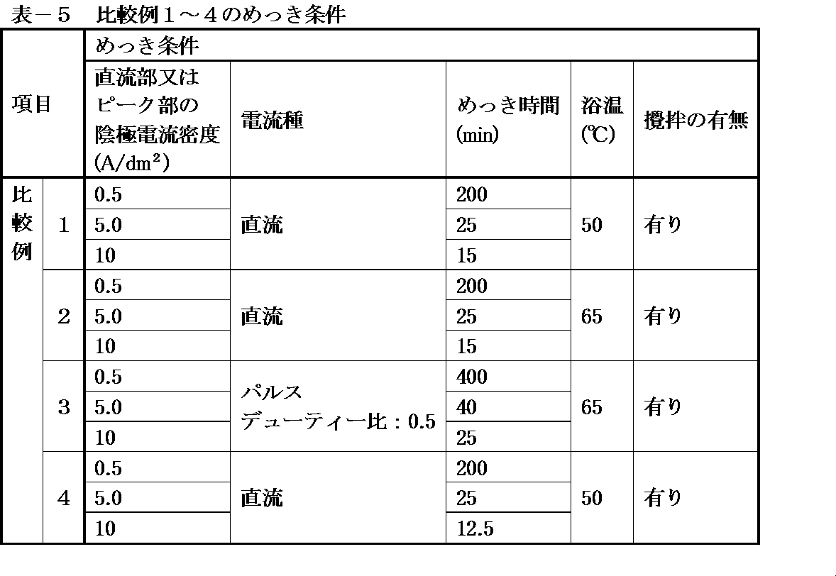
- a direct current or pulse current is used as the plating current for the substrate to be plated and the anode 7 in the copper-nickel alloy electroplating bath.
- the cathode current density is usually 0.01 to 10 A / dm 2 , preferably 0.1 to 8.0 A / dm 2 .
- the plating time is usually in the range of 1 to 1200 minutes, preferably in the range of 15 to 800 minutes, depending on the required plating film thickness and current conditions.
- the bath temperature is usually 15 to 70 ° C., preferably 20 to 60 ° C. Stirring of the bath can be performed by mechanical liquid stirring such as air, liquid flow, cathode rocker, paddle (not shown).
- the film thickness can be in a wide range, but is generally 0.5 to 100 ⁇ m, preferably 3 to 50 ⁇ m.
- copper-nickel alloy electroplating is performed while adjusting the oxidation-reduction potential, thereby precipitating copper and nickel on an object to be plated at an arbitrary alloy ratio.
- a plating film having a uniform composition can be obtained.
- the bath state can be stably maintained, and a good copper-nickel alloy electroplating film can be obtained even if the plating bath (plating solution) is used continuously for a long period of time. it can.
- a copper-nickel plating film with an arbitrary alloy ratio and a uniform composition can be obtained over a wide range of current density on the object to be plated as described above, and it has excellent bath stability and can be used continuously for a long time.
- the composition of the plating bath and the plating conditions can be arbitrarily changed in accordance with the purpose of obtaining the nickel alloy plating.
- SPCC iron plate
- Teflon registered trademark
- Examples 1 to 4 and Comparative Examples 1 to 4 Next, (1) the plating solution shown in Table 1 was put into the plating tank 2 in which the diaphragm 14 (polypropylene cloth) was installed between the anode chamber 6 and the cathode chamber 4, (2) A copper plate anode (anode 7) is installed in the anode chamber 6, and the test piece (plating object) is installed in the cathode chamber 4.
- the diaphragm 14 polypropylene cloth
- the plating film thickness and alloy composition, plating surface condition, and plating appearance evaluation were performed as follows. (1) The thickness of the plating was measured with a fluorescent X-ray analyzer. (2) For the alloy composition of plating, the alloy composition of the plating cross section was measured with an energy dispersive X-ray analyzer, and the uniformity of the plating film was evaluated. (3) The plating surface state was observed and evaluated with a scanning electron microscope. (4) The plating appearance was visually observed.
- the plating solution having the composition shown in Table 4 was divided into four chambers: (1) an anode chamber 6, an anode chamber oxidation-reduction potential adjustment tank 10, a cathode chamber 4, and a cathode chamber oxidation-reduction potential adjustment tank 8. Not put in a single tank, (2) A copper plate was placed on the anode, and the above test piece similar to that used in the examples was placed on the cathode. Electricity was applied between the cathode and the anode, and plating was performed under the conditions shown in Table-5. Table 6 shows the film thickness and alloy composition of the obtained plating, the plating surface condition, and the results of plating appearance evaluation (including color tone, smoothness and gloss).
- Copper salt species copper sulfamate (II) (Example 1), copper sulfate (II) (Example 4), copper acetate (II) (Example 2), copper methanesulfonate (II) (Example 3)
- Nickel salt species nickel sulfamate (Example 1), nickel sulfate (Example 4), nickel acetate (Example 2), nickel methanesulfonate (Example 3) pH adjuster: sodium hydroxide (Examples 1, 2 and 3), potassium hydroxide (Example 4)
- Copper salt species copper sulfamate (II) (Comparative Example 1), copper sulfate (II) (Comparative Example 4), copper acetate (II) (Comparative Example 2), copper methanesulfonate (II) (Comparative Example 3)
- Nickel salt type nickel sulfamate (Comparative Example 1), nickel sulfate (Comparative Example 4), nickel acetate (Comparative Example 2), nickel methanesulfonate (Comparative Example 3) pH adjuster: sodium hydroxide (Comparative Examples 1, 2, and 3), potassium hydroxide (Comparative Example 4)
Landscapes
- Chemical & Material Sciences (AREA)
- Engineering & Computer Science (AREA)
- Materials Engineering (AREA)
- Metallurgy (AREA)
- Organic Chemistry (AREA)
- Chemical Kinetics & Catalysis (AREA)
- Electrochemistry (AREA)
- Mechanical Engineering (AREA)
- Automation & Control Theory (AREA)
- Electroplating Methods And Accessories (AREA)
- Electroplating And Plating Baths Therefor (AREA)
Abstract
Description
(1)銅とニッケルの析出電位が約0.6V離れており、銅が優先的に析出してしまうこと、
(2)めっき浴が不安定で金属水酸化等の不溶性化合物を生じてしまうこと、
(3)通電によりめっき組成が変動、均一組成の皮膜が安定して得られないこと、
(4)液寿命が短いこと、
などが挙げられる。
このように構成された本発明によれば、隔膜を安価に構成することができる。
このように構成された本発明によれば、陰極室及び陽極室内の酸化還元電位を正確に適正値に維持することができる。
このように構成された本発明によれば、良好な銅-ニッケル合金電気めっき皮膜を得ることができる。
図1は、本発明の第1実施形態による銅-ニッケル合金電気めっき装置の断面図である。
また、陰極室4内には陰極5(被めっき物)が、陽極室6内には陽極7が、めっき液に浸漬されるように夫々配置される。
隔膜14は、陰極室4と陽極室6を通電可能に仕切るように構成されている。隔膜14としては、ポリエステル、ポリプロピレン、カネカロン、サラン、PTFE等の布、または中性隔膜として、ポリエチレンテレフタレート樹脂基材でポリフッ化ビニリデン樹脂酸化チタン/ショ糖脂肪酸エステル膜材のもの等、またはイオン交換膜として、カチオン交換膜を使用することができる。
本実施形態の銅-ニッケル合金電気めっき装置1には、酸化還元電位を調整するための構成として、陰極室電位測定装置38と、陰極室調整剤添加装置40と、陽極室電位測定装置42と、陽極室調整剤添加装置44と、陰極室調整剤添加装置40及び陽極室調整剤添加装置44に接続された制御部46が備えられている。
陰極室調整剤添加装置40は、陰極室酸化還元電位調整槽8内のめつき液に酸化還元電位調整剤を添加するように構成されている。
同様に、陽極室電位測定装置42は、陽極室6内に配置され、陽極室6内のめっき液の酸化還元電位を測定するように構成されている。
陽極室調整剤添加装置44は、陽極室酸化還元電位調整槽10内のめつき液に酸化還元電位調整剤を添加するように構成されている。
この制御部46による酸化還元電位の調整は、銅-ニッケル合金電気めっき装置1の作動中、常時実施される。
図2は、本発明の第2実施形態による銅-ニッケル合金電気めっき装置の断面図である。上述した第1実施形態においては、陰極室4と陰極室酸化還元電位調整槽8、陽極室6と陽極室酸化還元電位調整槽10が夫々隣接して配置され、オーバーフローさせることによりめっき液を循環させていたが、本実施形態においては酸化還元電位調整槽が分離されている点が第1実施形態とは異なる。従って、ここでは、本発明の第2実施形態の、第1実施形態とは異なる点を説明し、同様の構成、作用、効果については説明を省略する。
また、陰極室104内には陰極105(被めっき物)が、陽極室106内には陽極107が、めっき液に浸漬されるように夫々配置される。
一方、陽極室106内には、隔壁112と陽極107の間にスラッジ堤防124が設けられている。スラッジ堤防124は、陽極室106の底面から所定の高さまで延びる壁により構成され、沈積したスラッジが隔壁112の方へ移動するのを防止している。
本実施形態において使用される銅-ニッケル合金電気めっき浴は、(a)銅塩及びニッケル塩、(b)金属錯化剤、(c)導電性付与塩、(d)含硫黄有機化合物、及び(e)酸化還元電位調整剤を含有してなる。
銅塩としては、硫酸銅、ハロゲン化第二銅、スルファミン酸銅、メタンスルホン酸銅、酢酸第二銅、塩基性炭酸銅などが挙げられるがこれに限定されない。これらの銅塩は、単独で使用してもよく、又は2種以上を混合して使用してもよい。ニッケル塩としては、硫酸ニッケル、ハロゲン化ニッケル、塩基性炭酸ニッケル、スルファミン酸ニッケル、酢酸ニッケル、メタンスルホン酸ニッケルなどが挙げられるがこれに限定されない。これらのニッケル塩は、単独で使用してもよく、又は2種以上を混合して使用してもよい。銅塩とニッケル塩のめっき浴中の濃度は、求められるめっき皮膜の組成により種々選定する必要があるが、銅イオンとして好ましくは0.5~40g/L、より好ましくは2~30g/Lであり、ニッケルイオンとして好ましくは0.25~80g/L、より好ましくは0.5~50g/Lである。また、めっき浴中の銅イオンとニッケルイオンの合計濃度は、好ましくは0.0125~2.0モル/L、より好ましくは0.04~1.25モル/Lである。
金属錯化剤は銅及びニッケルである金属を安定化させる。金属錯化剤としては、モノカルボン酸、ジカルボン酸、ポリカルボン酸、オキシカルボン酸、ケトカルボン酸、アミノ酸、アミノカルボン酸、及びこれらの塩などが挙げられるがこれに限定されない。具体的には、マロン酸、マレイン酸、コハク酸、トリカルバリル酸、クエン酸、酒石酸、リンゴ酸、グルコン酸、2-スルホエチルイミノ-N,N-ジ酢酸、イミノジ酢酸、ニトリロトリ酢酸、EDTA、トリエチレンジアミンテトラ酢酸、ヒドロキシエチルイミノジ酢酸、グルタミン酸、アスパラギン酸、β-アラニン-N,N-ジ酢酸などが挙げられる。これらの中でも、好ましくはマロン酸、クエン酸、リンゴ酸、グルコン酸、EDTA、ニトリロトリ酢酸、グルタミン酸である。また、これらカルボン酸の塩としては、マグネシウム塩、ナトリウム塩、カリウム塩、アンモニウム塩などが挙げられるがこれに限定されない。これらの金属錯化剤は、単独で使用してもよく、又は2種以上を混合して使用してもよい。金属錯化剤のめっき浴中の濃度は、好ましくは浴中金属イオン濃度(モル濃度)の0.6~2倍、より好ましくは0.7~1.5倍である。
導電性付与塩は、銅-ニッケル合金電気めっき浴に電導性を付与する。本発明において、導電性付与塩としては、無機ハロゲン化塩、無機硫酸塩、低級アルカン(好ましくは、C 1~4)スルホン酸塩、及びアルカノール(好ましくは、C 1~4)スルホン塩が挙げられる。
無機ハロゲン化塩としては、マグネシウム、ナトリウム、カリウム、アンモニウムの塩化塩、臭化塩、ヨウ化塩などが挙げられるがこれに限定されない。これらの無機ハロゲン化塩は、単独で使用してもよく、又は2種以上を混合して使用してもよい。無機ハロゲン化塩のめっき浴中の濃度は、好ましくは0.1~2モル/L、より好ましくは0.2~1モル/Lである。
無機硫酸塩としては、硫酸マグネシウム、硫酸ナトリウム、硫酸カリウム、硫酸アンモニウムなどが挙げられるがこれに限定されない。これらの無機硫酸塩は、単独で使用してもよく、又は2種以上を混合して使用してもよい。
低級アルカンスルホン酸塩及びアルカノールスルホン塩としては、マグネシウム塩、ナトリウム塩、カリウム塩、アンモニウム塩などが挙げられ、より具体的には、メタンスルホン酸、2-ヒドロキシプロパンスルホン酸のマグネシウム、ナトリウム、カリウム、アンモニウム塩などが挙げられるがこれに限定されない。これらのスルホン酸塩は、単独で使用してもよく、又は2種以上を混合して使用してもよい。
硫酸塩及び/又は前記スルホン酸塩のめっき浴中の濃度は、好ましくは0.25~1.5モル/L、より好ましくは0.5~1.25モル/Lである。
また、導電性付与塩として、互いに異なる複数の導電性付与塩を用いると、さらに効果的である。好ましくは導電性付与塩として、無機ハロゲン化塩と、無機硫酸塩及び前記スルホン酸塩からなる群より選ばれる塩とを含有させるとよい。
含硫黄有機化合物としては、好ましくはジスルフィド化合物、含硫アミノ酸、ベンゾチアゾリルチオ化合物、及びそれらの塩からなる群より選ばれる化合物が挙げられる。
ジスルフィド化合物としては、一般式(I)で表されるジスルフィド化合物などが挙げられるがこれに限定されない。
A-R1-S-S-R2-A (I)
(式中、R1及びR2は炭化水素基を表し、AはSO3Na基、SO3H基、OH基、NH2基又はNO2基を表す。)
式中、好ましい炭化水素基はアルキレン基であり、より好ましくは炭素数1~6のアルキレン基である。ジスルフィド化合物の具体例としては、ビスソディウムスルホエチルジスルフィド、ビスソディウムスルホプロピルジスルフィド、ビスソディウムスルホペンチルジスルフィド、ビスソディウムスルホヘキシルジスルフィド、ビススルホエチルジスルフィド、ビススルホプロピルジスルフィド、ビススルホペンチルジスルフィド、ビスアミノエチルジスルフィド、ビスアミノプロピルジスルフィド、ビスアミノブチルジスルフィド、ビスアミノペンチルジスルフィド、ビスヒドロキシエチルジスルフィド、ビスヒドロキシプロピルジスルフィド、ビスヒドロキシブチルジスルフィド、ビスヒドロキシペンチルジスルフィド、ビスニトロエチルジスルフィド、ビスニトロプロピルジスルフィド、ビスニトロブチルジスルフィド、ソディウムスルホエチルプロピルジスルフィド、スルホブチルプロピルジスルフィドなどが挙げられるがこれに限定されない。これらのジスルフィド化合物のなかでも、ビスソディウムスルホプロピルジスルフィド、ビスソディウムスルホブチルジスルフィド、ビスアミノプロピルジスルフィドが好ましい。
含硫アミノ酸としては、一般式(II)で表される含硫アミノ酸などが挙げられるがこれに限定されない。
R-S-(CH2)nCHNHCOOH (II)
(式中、Rは炭化水素基、-H又は-(CH2)nCHNHCOOHを表し、nはそれぞれ独立に1~50である。)
式中、好ましい炭化水素基はアルキル基であり、より好ましくは炭素数1~6のアルキル基である。含硫アミノ酸の具体例としては、メチオニン、シスチン、システイン、エチオニン、シスチンジスルホキシド、シスタチオニンなどが挙げられるがこれに限定されない。
ベンゾチアゾリルチオ化合物としては、一般式(III)で表されるベンゾチアゾリル化合物などが挙げられるがこれに限定されない。
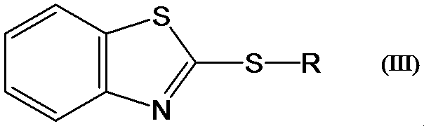
式中、好ましい炭化水素基はアルキル基であり、より好ましくは炭素数1~6のアルキル基である。また、n=1~5である。ベンゾチアゾリルチオ化合物の具体例としては、2-ベンゾチアゾリルチオ酢酸、3-(2-ベンゾチアゾリルチオ)プロピオン酸などが挙げられるがこれに限定されない。また、その塩としては、硫酸塩、ハロゲン化塩、メタンスルホン酸塩、スルファミン酸塩、酢酸塩などが挙げられるがこれに限定されない。
これらのジスルフィド化合物、含硫アミノ酸、ベンゾチアゾリルチオ化合物及びそれらの塩は、単独で使用してもよく、又は2種以上を混合して使用してもよい。ジスルフィド化合物、含硫アミノ酸、ベンゾチアゾリルチオ化合物及びそれらの塩からなる群より選ばれる化合物のめっき浴中の濃度は、好ましくは0.01~10g/L、より好ましくは0.05~5g/Lである。
スルホン酸化合物及びその塩としては、芳香族スルホン酸、アルケンスルホン酸、アルキンスルホン酸、及びそれらの塩などが挙げられるがこれに限定されない。具体的には、1,5-ナフタレンジスルホン酸ナトリウム、1,3,6-ナフタレントリスルホン酸ナトリウム、2-プロペン-1-スルホン酸ナトリウムなどが挙げられるがこれに限定されない。
スルフィミド化合物及びその塩としては、安息香酸スルフィミド(サッカリン)及びその塩などが挙げられるがこれに限定されない。具体的には、サッカリンナトリウムなどが挙げられるがこれに限定されない。
スルファミン酸化合物及びその塩としては、アセスルファムカリウム、N-シクロヘキシルスルファミン酸ナトリウムなどが挙げられるがこれに限定されない。
スルホンアミド及びその塩としては、パラトルエンスルホンアミドなどが挙げられるがこれに限定されない。
これらのスルホン酸化合物、スルフィミド化合物、スルファミン酸化合物、スルホンアミド、及びそれらの塩は、単独で使用してもよく、又は2種以上を混合して使用してもよい。スルホン酸化合物、スルフィミド化合物、スルファミン酸化合物、スルホンアミド、及びそれらの塩からなる群より選ばれる化合物のめっき浴中の濃度は、好ましくは0.2~5g/L、より好ましくは0.4~4g/Lである。
酸化還元電位調整剤は、好ましくは酸化剤であり、例えば無機系乃至有機系の酸化剤である。このような酸化剤としは、例えば過酸化水素水、水溶性オキソ酸及びその塩が挙げられる。水溶性オキソ酸及びその塩には無機系及び有機系オキソ酸が含まれる。
陰極(被めっき物)と陽極間で通電して電気めっきする際に、陰極で2価銅イオンは還元反応により金属銅として析出し、次いで析出した金属銅は溶解反応等により1価の銅イオンを生成する。そして、このような1価銅イオンの生成により、めっき浴の酸化還元電位は低下する。ORP調整剤は、1価銅イオンを酸化して2価銅イオンとすることでめっき浴の酸化還元電位の低下を防止する1価銅イオンの酸化剤として作用するものと推測される。
好ましい無機系オキソ酸としては、次亜塩素酸、亜塩素酸、塩素酸、過塩素酸、臭素酸等のハロゲンオキソ酸及びそれらのアルカリ金属塩、硝酸及びそのアルカリ金属塩、並びに過硫酸及びそのアルカリ金属塩が挙げられる。
好ましい有機系オキソ酸及びその塩としては、3-ニトロベンゼンスルホン酸ナトリウム等の芳香族スルホン酸塩、過酢酸ナトリウム等の過カルボン酸塩が挙げられる。
またPH緩衝剤として用いられる水溶性の無機、有機化合物およびそれらのアルカリ金属塩もORP調整剤として使用できる。このようなORP調整剤としては、好ましくはホウ酸、リン酸、炭酸、及びそれらのアルカリ金属塩など、またギ酸、酢酸、コハク酸等のカルボン酸及びそれらのアルカリ金属塩などが挙げられる。
このようなORP調整剤は各々単独で用いてもよく、また2種以上混合して用いてもよい。ORP調整剤が酸化剤の場合、添加量としては、通常、0.01~5g/Lの範囲、好ましくは0.05~2g/Lの範囲で用いられる。また、ORP調整剤がPH緩衝剤の場合は、通常、2~60g/Lの範囲、好ましくは5~40g/Lの範囲で用いられる。
浴中の酸化還元電位(ORP)が20mV(vs.Ag/AgCl)以下になると、めっきの析出が粗くなり凹凸のある表面となる。なお、浴中の酸化還元電位(ORP)の上限に制限はないが、350mV(vs.Ag/AgCl)以上では、浴中に含有されている有機物、即ち、(b)金属錯化剤、(d)含硫黄有機化合物等に影響を及ぼし、それらの効果が低下することがあるので好ましくない。
水溶性界面活性剤としては、イオン性に関係なく、アニオン界面活性剤、カチオン界面活性剤、両性界面活性剤、ノニオン界面活性剤のうちいずれも使用可能であるが、好ましくはノニオン界面活性剤である。エチレンオキサイド若しくはプロピレンオキサイドの重合基、又はエチレンオキサイドとプロピレンオキサイドの共重合基を有するが、それらの重合度は5~250、好ましくは10~150である。これらの水溶性界面活性剤は、単独で使用してもよく、又は2種以上を混合して使用してもよい。水溶性界面活性剤のめっき浴中の濃度は、好ましくは0.05~5g/L、より好ましくは0.1~2g/Lである。
水溶性合成高分子としては、グリシジルエーテルと多価アルコールとの反応生成物が挙げられる。グリシジルエーテルと多価アルコールとの反応生成物は、銅-ニッケル合金電気めっき皮膜を緻密化させ、さらにめっき組成の均一化に効果がある。
グリシジルエーテルと多価アルコールとの反応生成物の反応原料であるグリシジルエーテルとしては、分子内に二個以上のエポキシ基を含有するグリシジルエーテル、及び分子内に一個以上の水酸基と一個以上のエポキシ基とを含有するグリシジルエーテルなどが挙げられるがこれに限定されない。具体的には、グリシドール、グリセロールポリグリシジルエーテル、エチレングリコールジグリシジルエーテル、ポリエチレングリコールジグリシジルエーテル、ポリプロピレングリコールジグリシジルエーテル、ソルビトールポリグリシジルエーテルなどである。
多価アルコールとしては、エチレングリコール、プロピレングリコール、スリセリン、ポリグリセリンなどが挙げられるがこれに限定されない。
グリシジルエーテルと多価アルコールとの反応生成物は、好ましくはグリシジルエーテルのエポキシ基と多価アルコールの水酸基の縮合反応により得られる水溶性重合物である。
これらのグリシジルエーテルと多価アルコールとの反応生成物は、単独で使用してもよく、又は2種以上を混合して使用してもよい。グリシジルエーテルと多価アルコールとの反応生成物のめっき浴中の濃度は、好ましくは0.05~5g/L、より好ましくは0.1~2g/Lである。
電気めっきをする際には、陽極として、カーボン、白金、白金めっきしたチタン、酸化インジウムを被覆したチタンなどの不溶解性陽極を使用することができる。また、銅、ニッケル、銅-ニッケル合金、銅とニッケルを併用した可溶性陽極なども使用できる。
さらに、本実施形態における電気めっきにおいては、めっき槽中の、被めっき基板(陰極)と陽極電極が隔膜14により分離されている。隔膜14としては、好ましくは中性隔膜あるいはイオン交換膜である。中性隔膜としては、ポリエチレンテレフタレート樹脂基材でポリフッ化ビニリデン樹脂酸化チタン/ショ糖脂肪酸エステル膜材のものなどを挙げることができる。また、イオン交換膜としては、カチオン交換膜が適している。
本実施形態における銅-ニッケル合金電気めっき浴により、析出金属皮膜の銅/ニッケル組成比率が5/95~99/1の任意の組成のめっき皮膜を得ることができるが、好ましくは20/80~98/2であり、より好ましくは40/60~95/5である。
陰極電流密度は、通常0.01~10A/dm2、好ましくは0.1~8.0A/dm2である。
めっき時間は要求されるめっきの膜厚、電流条件にもよるが、通常1~1200分の範囲、好ましくは15~800分の範囲である。
浴温は、通常15~70℃、好ましくは20~60℃である。浴の撹拌は、エアー、液流、カソードロッカー、パドル(以上、図示せず)などの機械的な液撹拌を行うことができる。膜厚は、広い範囲のものが可能であるが、一般に0.5~100μm、好ましくは3~50μmである。
なお、評価用として使用した試験片の、銅ストライクめっきの膜厚は、銅-ニッケル合金電気めっきの膜厚に比べ極端に薄く、銅-ニッケル合金電気めっきの膜厚及び合金組成への影響は無視できるレベルである。
次に、表-1に示すめっき液を
(1)陽極室6と陰極室4の間に隔膜14(ポリプロピレン製の布)を設置しためっき槽2に入れ、
(2)陽極室6に銅板陽極(陽極7)を、陰極室4に上記試験片(被めっき物)を設置し、
(3)陽極室6と陽極室酸化還元電位調整槽10との循環濾過を行い、更に、
(4)陰極室4と陰極室酸化還元電位調整槽8との循環濾過を行い、
(5)陽極室酸化還元電位調整槽10、及び陰極室酸化還元電位調整槽8により酸化還元電位(ORP)を調整しながら、
陰極と陽極間で通電し、表-2の条件でめっきを行った。得られためっきの膜厚と合金組成、めっき表面状態、及びめっき外観評価(色調、平滑性及び光沢性を含む)の結果を表-3に示す。
なお、本実施例では、酸化還元電位(ORP)調整のための薬品として、過酸化水素水を使用した。
(1)めっきの膜厚は、蛍光X線分析装置により測定した。
(2)めっきの合金組成は、めっき断面の合金組成をエネルギー分散型X線分析装置で測定し、めっき皮膜の均一性の評価を行った。
(3)めっき表面状態は走査型電子顕微鏡で観察し、評価した。
(4)めっき外観は、目視にて観察した。
(1)陽極室6、陽極室酸化還元電位調整槽10、陰極室4、陰極室酸化還元電位調整槽8の4つの室に分割されていない、単一槽に入れ、
(2)陽極に銅板を設置し、陰極に実施例で使用したものと同様の上記の試験片を設置し、陰極と陽極間で通電し、表-5の条件でめっきを行った。得られためっきの膜厚と合金組成、めっき表面状態、及びめっき外観評価(色調、平滑性及び光沢性を含む)の結果を表-6に示す。
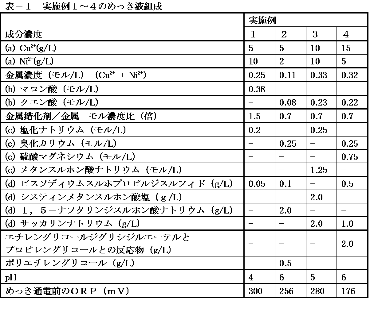
ニッケル塩種:スルファミン酸ニッケル(実施例1)、硫酸ニッケル(実施例4)、酢酸ニッケル(実施例2)、メタンスルホン酸ニッケル(実施例3)
pH調整剤:水酸化ナトリウム(実施例1、2、及び3)、水酸化カリウム(実施例4)


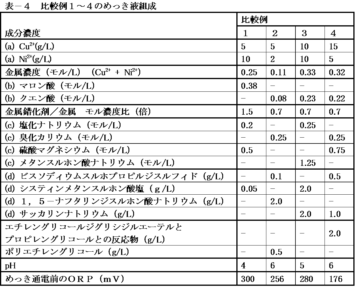
ニッケル塩種:スルファミン酸ニッケル(比較例1)、硫酸ニッケル(比較例4)、酢酸ニッケル(比較例2)、メタンスルホン酸ニッケル(比較例3)
pH調整剤:水酸化ナトリウム(比較例1、2、及び3)、水酸化カリウム(比較例4)

2 めっき槽
4 陰極室
5 陰極(被めっき物)
6 陽極室
7 陽極
8 陰極室酸化還元電位調整槽
10 陽極室酸化還元電位調整槽
12 隔壁
12a 開口部
14 隔膜
16 陰極側遮蔽板
18 陰極室堰部
20a、20b 仕切壁
22 折り返し通路
24 スラッジ堤防
26 陽極室堰部
28a、28b 仕切壁
30 折り返し通路
32 陰極室移送装置
32a 陰極室吸込パイプ
32b 陰極室吐出パイプ
32c 陰極室濾過装置
34 陽極室移送装置
34a 陽極室吸込パイプ
34b 陽極室吐出パイプ
34c 陽極室濾過装置
36 電源部
38 陰極室電位測定装置
40 陰極室調整剤添加装置
42 陽極室電位測定装置
44 陽極室調整剤添加装置
46 制御部
100 本発明の第2実施形態の銅-ニッケル合金電気めっき装置
102 めっき槽本槽
104 陰極室
105 陰極(被めっき物)
106 陽極室
107 陽極
108 陰極室酸化還元電位調整槽
110 陽極室酸化還元電位調整槽
112 隔壁
112a 開口部
114 隔膜
116 陰極側遮蔽板
116a 開口部
124 スラッジ堤防
132 陰極室第1移送装置
132a 陰極室吸込パイプ
132b 陰極室吐出パイプ
133 陰極室第2移送装置
133a 陰極室吸込パイプ
133b 陰極室吐出パイプ
134 陽極室第1移送装置
134a 陽極室吸込パイプ
134b 陽極室吐出パイプ
135 陽極室第2移送装置
135a 陽極室吸込パイプ
135b 陽極室吐出パイプ
138 陰極室電位測定装置
140 陰極室調整剤添加装置
142 陽極室電位測定装置
144 陽極室調整剤添加装置
146 制御部
147 陰極室酸化還元電位調整槽撹拌器
148 陽極室酸化還元電位調整槽撹拌器
Claims (7)
- 銅-ニッケル合金電気めっき装置であって、
被めっき物を内部に配置する陰極室と、
陽極室と、
この陽極室の内部に配置された陽極と、
上記陰極室と上記陽極室を隔てるように配置された、通電可能な隔膜と、
上記陰極室内のめっき液の酸化還元電位を調整するための陰極室酸化還元電位調整槽と、
上記陽極室内のめっき液の酸化還元電位を調整するための陽極室酸化還元電位調整槽と、
上記被めっき物と上記陽極の間に電流を流す電源部と、
を有することを特徴とする電気めっき装置。 - さらに、上記陰極室内及び上記陰極室酸化還元電位調整槽内のめっき液を循環させる陰極室循環装置と、
上記陽極室内及び上記陽極室酸化還元電位調整槽内のめっき液を循環させる陽極室循環装置と、を有する請求項1記載の電気めっき装置。 - 上記隔膜は、ポリエステル、ポリプロピレン、カネカロン、サラン又はPTFE製の布、中性隔膜、又はイオン交換膜である請求項1又は2記載の電気めっき装置。
- 上記陰極室循環装置は、上記陰極室内のめっき液を上記陰極室酸化還元電位調整槽にオーバーフローさせる陰極室堰部と、上記陰極室酸化還元電位調整槽内のめっき液を上記陰極室に移送する陰極室移送装置と、この陰極室移送装置によって移送されるめっき液を濾過する陰極室濾過装置と、を備え、
上記陽極室循環装置は、上記陽極室酸化還元電位調整槽内のめっき液を上記陽極室にオーバーフローさせる陽極室堰部と、上記陽極室内のめっき液を上記陽極室酸化還元電位調整槽に移送する陽極室移送装置と、この陽極室移送装置によって移送されるめっき液を濾過する陽極室濾過装置と、を備えている請求項2又は3記載の電気めっき装置。 - 上記陰極室循環装置は、上記陰極室内のめっき液を上記陰極室酸化還元電位調整槽に移送する陰極室第1移送装置と、上記陰極室酸化還元電位調整槽内のめっき液を上記陰極室に移送する陰極室第2移送装置と、上記陰極室と上記陰極室酸化還元電位調整槽の間で循環されるめっき液を濾過する陰極室濾過装置と、を備え、
上記陽極室循環装置は、上記陽極室酸化還元電位調整槽内のめっき液を上記陽極室に移送する陽極室第1移送装置と、上記陽極室内のめっき液を上記陽極室酸化還元電位調整槽に移送する陽極室第2移送装置と、上記陽極室と上記陽極室酸化還元電位調整槽の間で循環されるめっき液を濾過する陽極室濾過装置と、を備えている請求項2又は3記載の電気めっき装置。 - さらに、上記陰極室内のめっき液の酸化還元電位を測定する陰極室電位測定装置と、
上記陽極室内のめっき液の酸化還元電位を測定する陽極室電位測定装置と、
上記陰極室酸化還元電位調整槽に酸化還元電位調整剤を添加する陰極室調整剤添加装置と、
上記陽極室酸化還元電位調整槽に酸化還元電位調整剤を添加する陽極室調整剤添加装置と、
上記陰極室電位測定装置によって測定された酸化還元電位、及び上記陽極室電位測定装置によって測定された酸化還元電位に基づいて、上記陰極室調整剤添加装置及び上記陽極室調整剤添加装置を制御する制御部と、を有する請求項1乃至5の何れか1項に記載の電気めっき装置。 - さらに、上記陰極室、上記陽極室、上記陰極室酸化還元電位調整槽、及び上記陽極室酸化還元電位調整槽に収容された銅-ニッケル合金電気めっき液を有し、この銅-ニッケル合金電気めっき液が、(a)銅塩及びニッケル塩、(b)金属錯化剤、(c)導電性付与塩、及び(d)含硫黄有機化合物、を含有する請求項1乃至6の何れか1項に記載の電気めっき装置。
Priority Applications (10)
| Application Number | Priority Date | Filing Date | Title |
|---|---|---|---|
| MX2017004574A MX2017004574A (es) | 2014-10-17 | 2015-06-25 | Aparato de electroenchapado de aleacion de cobre-niquel. |
| KR1020177009288A KR101916614B1 (ko) | 2014-10-17 | 2015-06-25 | 구리-니켈 합금 전기 도금 장치 |
| SG11201703049XA SG11201703049XA (en) | 2014-10-17 | 2015-06-25 | Copper-Nickel Alloy Electroplating Apparatus |
| CN201580055714.5A CN107075713B (zh) | 2014-10-17 | 2015-06-25 | 铜-镍合金电镀装置 |
| EP15849917.8A EP3208364B1 (en) | 2014-10-17 | 2015-06-25 | Copper-nickel alloy electroplating device |
| US15/519,474 US10538854B2 (en) | 2014-10-17 | 2015-06-25 | Copper-nickel alloy electroplating device |
| BR112017007630-6A BR112017007630A2 (ja) | 2014-10-17 | 2015-06-25 | Copper-nickel alloy electroplating device |
| MYPI2017000473A MY190427A (en) | 2014-10-17 | 2015-06-25 | Copper-nickel alloy electroplating apparatus |
| RU2017116979A RU2648811C1 (ru) | 2014-10-17 | 2015-06-25 | Устройство для нанесения гальванического покрытия из медно-никелевого сплава |
| PH12017500597A PH12017500597A1 (en) | 2014-10-17 | 2017-03-31 | Copper-nickel alloy electroplating apparatus |
Applications Claiming Priority (2)
| Application Number | Priority Date | Filing Date | Title |
|---|---|---|---|
| JP2014212524A JP6435546B2 (ja) | 2014-10-17 | 2014-10-17 | 銅−ニッケル合金電気めっき装置 |
| JP2014-212524 | 2014-10-17 |
Publications (1)
| Publication Number | Publication Date |
|---|---|
| WO2016059833A1 true WO2016059833A1 (ja) | 2016-04-21 |
Family
ID=55746382
Family Applications (1)
| Application Number | Title | Priority Date | Filing Date |
|---|---|---|---|
| PCT/JP2015/068332 Ceased WO2016059833A1 (ja) | 2014-10-17 | 2015-06-25 | 銅-ニッケル合金電気めっき装置 |
Country Status (13)
| Country | Link |
|---|---|
| US (1) | US10538854B2 (ja) |
| EP (1) | EP3208364B1 (ja) |
| JP (1) | JP6435546B2 (ja) |
| KR (1) | KR101916614B1 (ja) |
| CN (1) | CN107075713B (ja) |
| BR (1) | BR112017007630A2 (ja) |
| MX (1) | MX2017004574A (ja) |
| MY (1) | MY190427A (ja) |
| PH (1) | PH12017500597A1 (ja) |
| RU (1) | RU2648811C1 (ja) |
| SG (1) | SG11201703049XA (ja) |
| TW (1) | TWI651438B (ja) |
| WO (1) | WO2016059833A1 (ja) |
Families Citing this family (7)
| Publication number | Priority date | Publication date | Assignee | Title |
|---|---|---|---|---|
| JP6834070B2 (ja) * | 2016-06-13 | 2021-02-24 | 石原ケミカル株式会社 | 電気スズ及びスズ合金メッキ浴、当該メッキ浴を用いて電着物を形成した電子部品の製造方法 |
| KR101872734B1 (ko) * | 2017-07-20 | 2018-06-29 | 주식회사 익스톨 | 니켈 전기 도금액 및 이를 이용한 전기 도금 방법 |
| JP2020097764A (ja) * | 2018-12-18 | 2020-06-25 | トヨタ自動車株式会社 | 成膜装置、及びそれを用いた金属膜の形成方法 |
| CN110387573B (zh) * | 2019-07-04 | 2021-01-05 | 广州兴森快捷电路科技有限公司 | 多废液分流方法及电镀生产系统 |
| CA3109026A1 (en) | 2020-02-18 | 2021-08-18 | Magna Exteriors Inc. | Tailgate accessibility |
| CN112126953B (zh) * | 2020-09-10 | 2024-07-16 | 深圳市生利科技有限公司 | 一种铜-镍合金电镀工艺 |
| CN116265621A (zh) * | 2021-12-17 | 2023-06-20 | 盛美半导体设备(上海)股份有限公司 | 清洗电镀装置的方法 |
Citations (4)
| Publication number | Priority date | Publication date | Assignee | Title |
|---|---|---|---|---|
| JPH04198499A (ja) * | 1990-07-20 | 1992-07-17 | Asahi Glass Co Ltd | 電位調節機構を有する銅溶解槽 |
| WO2001068952A1 (en) * | 2000-03-17 | 2001-09-20 | Ebara Corporation | Method and apparatus for electroplating |
| JP2003183898A (ja) * | 2001-12-20 | 2003-07-03 | Toho Kako Kensetsu Kk | めっき液濃度自動調整装置及び方法 |
| JP2013159851A (ja) * | 2012-02-08 | 2013-08-19 | Ishihara Chem Co Ltd | 無電解ニッケル及びニッケル合金メッキ方法、並びに当該メッキ用の前処理液 |
Family Cites Families (10)
| Publication number | Priority date | Publication date | Assignee | Title |
|---|---|---|---|---|
| SU1019027A1 (ru) * | 1982-02-16 | 1983-05-23 | Проектно-конструкторский технологический институт машиностроения | Ванна дл гальванической обработки деталей |
| KR100660485B1 (ko) | 1998-11-30 | 2006-12-22 | 가부시키가이샤 에바라 세이사꾸쇼 | 도금장치 |
| CN1253606C (zh) * | 2001-02-23 | 2006-04-26 | 株式会社荏原制作所 | 镀铜溶液、镀敷方法和镀敷装置 |
| US20040007473A1 (en) * | 2002-07-11 | 2004-01-15 | Applied Materials, Inc. | Electrolyte/organic additive separation in electroplating processes |
| IES20030443A2 (en) * | 2003-06-16 | 2004-12-01 | Fraudhalt Ltd | A method and apparatus for determining if an optical disk originated from a valid source |
| US8128791B1 (en) * | 2006-10-30 | 2012-03-06 | Novellus Systems, Inc. | Control of electrolyte composition in a copper electroplating apparatus |
| US8694950B2 (en) * | 2010-07-24 | 2014-04-08 | Cadence Design Systems, Inc. | Methods, systems, and articles of manufacture for implementing electronic circuit designs with electrical awareness |
| JP5631775B2 (ja) * | 2011-02-24 | 2014-11-26 | 新光電気工業株式会社 | 複合めっき液 |
| US9518332B2 (en) * | 2011-03-17 | 2016-12-13 | Taiwan Semiconductor Manufacturing Company, Ltd. | Electrochemical plating |
| KR101649435B1 (ko) | 2012-04-19 | 2016-08-19 | 딥솔 가부시키가이샤 | 구리-니켈 합금 전기 도금 욕 및 도금 방법 |
-
2014
- 2014-10-17 JP JP2014212524A patent/JP6435546B2/ja active Active
-
2015
- 2015-06-25 BR BR112017007630-6A patent/BR112017007630A2/ja not_active IP Right Cessation
- 2015-06-25 MX MX2017004574A patent/MX2017004574A/es unknown
- 2015-06-25 WO PCT/JP2015/068332 patent/WO2016059833A1/ja not_active Ceased
- 2015-06-25 SG SG11201703049XA patent/SG11201703049XA/en unknown
- 2015-06-25 RU RU2017116979A patent/RU2648811C1/ru not_active IP Right Cessation
- 2015-06-25 EP EP15849917.8A patent/EP3208364B1/en active Active
- 2015-06-25 CN CN201580055714.5A patent/CN107075713B/zh not_active Expired - Fee Related
- 2015-06-25 KR KR1020177009288A patent/KR101916614B1/ko not_active Expired - Fee Related
- 2015-06-25 MY MYPI2017000473A patent/MY190427A/en unknown
- 2015-06-25 US US15/519,474 patent/US10538854B2/en not_active Expired - Fee Related
- 2015-08-06 TW TW104125581A patent/TWI651438B/zh not_active IP Right Cessation
-
2017
- 2017-03-31 PH PH12017500597A patent/PH12017500597A1/en unknown
Patent Citations (4)
| Publication number | Priority date | Publication date | Assignee | Title |
|---|---|---|---|---|
| JPH04198499A (ja) * | 1990-07-20 | 1992-07-17 | Asahi Glass Co Ltd | 電位調節機構を有する銅溶解槽 |
| WO2001068952A1 (en) * | 2000-03-17 | 2001-09-20 | Ebara Corporation | Method and apparatus for electroplating |
| JP2003183898A (ja) * | 2001-12-20 | 2003-07-03 | Toho Kako Kensetsu Kk | めっき液濃度自動調整装置及び方法 |
| JP2013159851A (ja) * | 2012-02-08 | 2013-08-19 | Ishihara Chem Co Ltd | 無電解ニッケル及びニッケル合金メッキ方法、並びに当該メッキ用の前処理液 |
Non-Patent Citations (1)
| Title |
|---|
| See also references of EP3208364A4 * |
Also Published As
| Publication number | Publication date |
|---|---|
| EP3208364A1 (en) | 2017-08-23 |
| CN107075713A (zh) | 2017-08-18 |
| JP2016079460A (ja) | 2016-05-16 |
| US10538854B2 (en) | 2020-01-21 |
| TWI651438B (zh) | 2019-02-21 |
| EP3208364A4 (en) | 2018-05-30 |
| BR112017007630A2 (ja) | 2018-01-30 |
| SG11201703049XA (en) | 2017-05-30 |
| RU2648811C1 (ru) | 2018-03-28 |
| CN107075713B (zh) | 2019-09-24 |
| TW201615900A (zh) | 2016-05-01 |
| JP6435546B2 (ja) | 2018-12-12 |
| KR20170053675A (ko) | 2017-05-16 |
| EP3208364B1 (en) | 2019-08-07 |
| PH12017500597A1 (en) | 2017-08-30 |
| US20170241040A1 (en) | 2017-08-24 |
| MX2017004574A (es) | 2017-07-17 |
| KR101916614B1 (ko) | 2018-11-07 |
| MY190427A (en) | 2022-04-21 |
Similar Documents
| Publication | Publication Date | Title |
|---|---|---|
| JP6435546B2 (ja) | 銅−ニッケル合金電気めっき装置 | |
| US9828686B2 (en) | Copper-nickel alloy electroplating bath and plating method | |
| JP6439172B2 (ja) | 銅−ニッケル合金電気めっき浴 | |
| CN102102218B (zh) | 在电解液中补充锡和制造合金的金属的方法 | |
| US20050173255A1 (en) | Electroplated quaternary alloys | |
| CN106591897B (zh) | 一种无氰离子液体镀铜溶液及镀铜工艺 | |
| TW201428143A (zh) | 藉由電鑄法但不使用有毒金屬或類金屬而獲致黃金合金沉積的方法 | |
| CN104388989A (zh) | 一种三价铬电镀液及制备方法 | |
| US20050173254A1 (en) | Nickel cobalt boron ternary alloys | |
| WO2005078163A1 (en) | Ternary and quaternary alloys to replace chromium |
Legal Events
| Date | Code | Title | Description |
|---|---|---|---|
| 121 | Ep: the epo has been informed by wipo that ep was designated in this application |
Ref document number: 15849917 Country of ref document: EP Kind code of ref document: A1 |
|
| WWE | Wipo information: entry into national phase |
Ref document number: 12017500597 Country of ref document: PH |
|
| ENP | Entry into the national phase |
Ref document number: 20177009288 Country of ref document: KR Kind code of ref document: A |
|
| WWE | Wipo information: entry into national phase |
Ref document number: MX/A/2017/004574 Country of ref document: MX |
|
| WWE | Wipo information: entry into national phase |
Ref document number: 11201703049X Country of ref document: SG |
|
| WWE | Wipo information: entry into national phase |
Ref document number: 15519474 Country of ref document: US |
|
| NENP | Non-entry into the national phase |
Ref country code: DE |
|
| REG | Reference to national code |
Ref country code: BR Ref legal event code: B01A Ref document number: 112017007630 Country of ref document: BR |
|
| REEP | Request for entry into the european phase |
Ref document number: 2015849917 Country of ref document: EP |
|
| ENP | Entry into the national phase |
Ref document number: 2017116979 Country of ref document: RU Kind code of ref document: A |
|
| ENP | Entry into the national phase |
Ref document number: 112017007630 Country of ref document: BR Kind code of ref document: A2 Effective date: 20170412 |