WO2016060161A1 - 路面状態予測方法及び路面状態予測システム - Google Patents
路面状態予測方法及び路面状態予測システム Download PDFInfo
- Publication number
- WO2016060161A1 WO2016060161A1 PCT/JP2015/079029 JP2015079029W WO2016060161A1 WO 2016060161 A1 WO2016060161 A1 WO 2016060161A1 JP 2015079029 W JP2015079029 W JP 2015079029W WO 2016060161 A1 WO2016060161 A1 WO 2016060161A1
- Authority
- WO
- WIPO (PCT)
- Prior art keywords
- road surface
- surface state
- estimated
- vehicle
- predicted
- Prior art date
- Legal status (The legal status is an assumption and is not a legal conclusion. Google has not performed a legal analysis and makes no representation as to the accuracy of the status listed.)
- Ceased
Links
Images





Classifications
-
- B—PERFORMING OPERATIONS; TRANSPORTING
- B60—VEHICLES IN GENERAL
- B60T—VEHICLE BRAKE CONTROL SYSTEMS OR PARTS THEREOF; BRAKE CONTROL SYSTEMS OR PARTS THEREOF, IN GENERAL; ARRANGEMENT OF BRAKING ELEMENTS ON VEHICLES IN GENERAL; PORTABLE DEVICES FOR PREVENTING UNWANTED MOVEMENT OF VEHICLES; VEHICLE MODIFICATIONS TO FACILITATE COOLING OF BRAKES
- B60T8/00—Arrangements for adjusting wheel-braking force to meet varying vehicular or ground-surface conditions, e.g. limiting or varying distribution of braking force
- B60T8/17—Using electrical or electronic regulation means to control braking
- B60T8/172—Determining control parameters used in the regulation, e.g. by calculations involving measured or detected parameters
-
- G—PHYSICS
- G01—MEASURING; TESTING
- G01B—MEASURING LENGTH, THICKNESS OR SIMILAR LINEAR DIMENSIONS; MEASURING ANGLES; MEASURING AREAS; MEASURING IRREGULARITIES OF SURFACES OR CONTOURS
- G01B21/00—Measuring arrangements or details thereof, where the measuring technique is not covered by the other groups of this subclass, unspecified or not relevant
- G01B21/30—Measuring arrangements or details thereof, where the measuring technique is not covered by the other groups of this subclass, unspecified or not relevant for measuring roughness or irregularity of surfaces
-
- G—PHYSICS
- G01—MEASURING; TESTING
- G01W—METEOROLOGY
- G01W1/00—Meteorology
- G01W1/10—Devices for predicting weather conditions
-
- G—PHYSICS
- G08—SIGNALLING
- G08G—TRAFFIC CONTROL SYSTEMS
- G08G1/00—Traffic control systems for road vehicles
- G08G1/01—Detecting movement of traffic to be counted or controlled
-
- G—PHYSICS
- G08—SIGNALLING
- G08G—TRAFFIC CONTROL SYSTEMS
- G08G1/00—Traffic control systems for road vehicles
- G08G1/01—Detecting movement of traffic to be counted or controlled
- G08G1/0104—Measuring and analyzing of parameters relative to traffic conditions
- G08G1/0108—Measuring and analyzing of parameters relative to traffic conditions based on the source of data
- G08G1/0112—Measuring and analyzing of parameters relative to traffic conditions based on the source of data from the vehicle, e.g. floating car data [FCD]
-
- G—PHYSICS
- G08—SIGNALLING
- G08G—TRAFFIC CONTROL SYSTEMS
- G08G1/00—Traffic control systems for road vehicles
- G08G1/01—Detecting movement of traffic to be counted or controlled
- G08G1/0104—Measuring and analyzing of parameters relative to traffic conditions
- G08G1/0125—Traffic data processing
- G08G1/0129—Traffic data processing for creating historical data or processing based on historical data
-
- G—PHYSICS
- G08—SIGNALLING
- G08G—TRAFFIC CONTROL SYSTEMS
- G08G1/00—Traffic control systems for road vehicles
- G08G1/01—Detecting movement of traffic to be counted or controlled
- G08G1/0104—Measuring and analyzing of parameters relative to traffic conditions
- G08G1/0137—Measuring and analyzing of parameters relative to traffic conditions for specific applications
- G08G1/0141—Measuring and analyzing of parameters relative to traffic conditions for specific applications for traffic information dissemination
-
- G—PHYSICS
- G08—SIGNALLING
- G08G—TRAFFIC CONTROL SYSTEMS
- G08G1/00—Traffic control systems for road vehicles
- G08G1/123—Traffic control systems for road vehicles indicating the position of vehicles, e.g. scheduled vehicles; Managing passenger vehicles circulating according to a fixed timetable, e.g. buses, trains, trams
- G08G1/127—Traffic control systems for road vehicles indicating the position of vehicles, e.g. scheduled vehicles; Managing passenger vehicles circulating according to a fixed timetable, e.g. buses, trains, trams to a central station ; Indicators in a central station
- G08G1/13—Traffic control systems for road vehicles indicating the position of vehicles, e.g. scheduled vehicles; Managing passenger vehicles circulating according to a fixed timetable, e.g. buses, trains, trams to a central station ; Indicators in a central station the indicator being in the form of a map
-
- B—PERFORMING OPERATIONS; TRANSPORTING
- B60—VEHICLES IN GENERAL
- B60T—VEHICLE BRAKE CONTROL SYSTEMS OR PARTS THEREOF; BRAKE CONTROL SYSTEMS OR PARTS THEREOF, IN GENERAL; ARRANGEMENT OF BRAKING ELEMENTS ON VEHICLES IN GENERAL; PORTABLE DEVICES FOR PREVENTING UNWANTED MOVEMENT OF VEHICLES; VEHICLE MODIFICATIONS TO FACILITATE COOLING OF BRAKES
- B60T2210/00—Detection or estimation of road or environment conditions; Detection or estimation of road shapes
- B60T2210/10—Detection or estimation of road conditions
- B60T2210/12—Friction
-
- G—PHYSICS
- G08—SIGNALLING
- G08G—TRAFFIC CONTROL SYSTEMS
- G08G1/00—Traffic control systems for road vehicles
- G08G1/123—Traffic control systems for road vehicles indicating the position of vehicles, e.g. scheduled vehicles; Managing passenger vehicles circulating according to a fixed timetable, e.g. buses, trains, trams
Definitions
- the present invention relates to a method for predicting a road surface state on which a vehicle travels, and in particular, predicts a road surface state using data and vehicle information of a road surface state estimated for a vehicle traveling in a predetermined range. Regarding the method.
- the vibration of the tire during traveling is detected, and the road surface state is estimated from the time series waveform of the detected tire vibration (for example, Patent Documents 1 to 4). 3) and a method of detecting a tire generated sound generated from a tire and estimating a road surface state from a sound pressure level of the detected tire generated sound (see, for example, Patent Document 4).
- the present invention has been made in view of the conventional problems, and an object of the present invention is to provide a method for accurately predicting a road surface state in a place within a predetermined range.
- a road surface state prediction method is calculated using a vehicle sensor mounted on a vehicle to obtain vehicle information that is information on the behavior of the vehicle during travel, and the vehicle information.
- Road surface estimation determination value used for estimation of road surface state, or a road surface comprising a step of predicting a road surface state of a place within a predetermined range using the estimated road surface state estimated using the road surface estimation determination value
- a time change or estimation of a road surface estimation determination value calculated using vehicle information acquired by a vehicle that has passed a place within a predetermined range.
- the predicted appearance ratio S Rp for each road surface condition is the appearance ratio of the road surface condition at the location within the predetermined range
- the predicted appearance ratio S Rp the calculated, Characterized by predicting the road surface condition in the serial location within a predetermined range.
- FIG. It is a figure which shows the structure of the road surface state prediction system which concerns on this Embodiment 1.
- FIG. It is a figure which shows the example of arrangement
- FIG. It is a figure which shows the structure of the road surface state prediction system which concerns on this Embodiment 2.
- FIG. It is a figure which shows the example of arrangement
- FIG. It is a figure which shows an example of a weather model. It is a figure which shows the occurrence frequency of the road surface state by weather and temperature. It is a figure which shows the predicted value of the road surface state correct
- FIG. It is a figure which shows the predicted value of the road surface state correct
- FIG. It is a figure which shows the prediction method of the road surface state which concerns on this Embodiment 5.
- FIG. It is a figure which shows the prediction method of the road surface state which concerns on this Embod
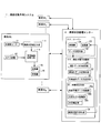
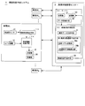
- FIG. 1 is a functional block diagram showing a configuration of a road surface condition prediction system 1 according to the first embodiment.
- Reference numeral 20 denotes a server including a receiver 21, data storage means 22, and a transmitter 23.
- Reference numeral 30 denotes an estimated road surface state estimated by a plurality of vehicles Wi at a plurality of times within a predetermined range. This is a road surface state prediction device that predicts the road surface state at a location within a predetermined range from the time variation of the above.
- “Number of vehicles N” is “total number of vehicles”, and when there are a plurality of data in a predetermined time and within a predetermined range of one vehicle, the plurality of data is Treat as separate data.
- the server 20 and the road surface state prediction device 30 are provided in the road surface state management center 2.
- the road surface state estimation unit 13, the vehicle information collection unit 14, and the road surface state prediction device 30 are configured by software of a computer, for example.
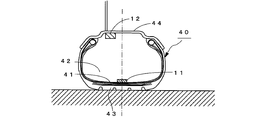
- the acceleration sensor 11 is arranged at a substantially central portion on the tire air chamber 42 side of the inner liner portion 41 of the tire 40, and receives vibration (tire vibration) input from the road surface R to the tread 43 of the tire 40. Is detected.
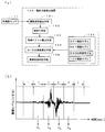
- the road surface state estimating means 13 uses the time series waveform of the tire vibration detected by the acceleration sensor 11 to estimate whether the running road surface is a DRY road surface, a WET road surface, a SNOW road surface, or an ICE road surface. As such a road surface state estimating means 13, for example, as shown in FIG.
- a vibration waveform extracting means 131 for extracting a time series waveform of tire vibration from the acceleration sensor 11, a windowing means 132, A feature vector calculation unit 133, a storage unit 134 for storing four road surface models, a kernel function calculation unit 135, and a road surface state determination unit 136, and a time series of tire vibration as shown in FIG.
- a feature vector X k (component) having vibration levels (a k1 to a km ) in a plurality of specific frequency bands as components from a time-series waveform for each time window extracted by applying a window function of a predetermined time width T to the waveform.
- a kernel function is calculated from these feature vectors and the feature vector for each road surface condition obtained in advance, and the value of the discriminant function using this kernel function From Examples include a road surface state determination device 13K configured to estimate whether the road surface state is a DRY road surface, a WET road surface, a SNOW road surface, or an ICE road surface.
- the feature vector for each road surface condition is a feature vector having as components components of vibration levels in a plurality of specific frequency bands when the test vehicle is run on the DRY road surface, the WET road surface, the SNOW road surface, and the ICE road surface.
- the road surface condition estimating means 13 may be provided in the tire 40 or on the vehicle body side.
- an arithmetic unit is provided on the tire 40 side, and a specific frequency band detected from the acceleration waveform is obtained. It is preferable that a band value used for estimating a road surface state such as a vibration level or a calculated value of the band value is calculated and sent to the road surface state estimating means 13.
- the vehicle information collection unit 14 collects the road surface state estimated by the road surface state estimation unit 13 (hereinafter referred to as an estimated road surface state) and the vehicle position data acquired by the GPS device 12 to identify the vehicle. Together with the vehicle ID of the vehicle as vehicle information of the vehicle.
- the vehicle information includes vehicle ID and vehicle information acquisition time data (time data). As the time data, an extraction time of an acceleration time series waveform, an acquisition time of position data, a data transmission time, or the like may be used. Since these times are almost the same time, there is no problem even if any time is used as the time data.
- the transmitter 15 collects the vehicle information from the transmission antenna (not shown) together with the estimated road surface state data collected by the vehicle information collecting means 14, the vehicle position data, and the vehicle ID for identifying the vehicle.
- the vehicle information is transmitted to the server 20 of the road surface state management center 2.
- the receiver 16 receives the road surface state prediction data at a place within a predetermined range, which is predicted by the road surface state prediction device 30 of the road surface state management center 2 and transmitted from the transmitter of the server 20.
- the driver can know the road surface state prediction result in a predetermined range. Further, if the prediction result of the road surface condition is fed back to the vehicle control, the traveling safety of the vehicle can be improved.
- the data is classified into data for each time and stored in the data storage means 22, and the road surface state prediction data in a predetermined range predicted by the road surface state prediction device 30 is transmitted from the transmitter 23 to the registered vehicle. .
- Vehicle information of each vehicle W i is classified and stored in the data storage means 22. Specifically, as shown in FIG. 4, the storage area 221 of the data storage means 22 has a plurality of times t (1) k (t ⁇ n1 to t ⁇ 1 ) at a predetermined location L 1 .
- the number of times n r at which data is acquired may be different depending on the location L r or may be the same.
- Data at each predetermined location L r is stored in time order.
- the data at time t k is data acquired within a predetermined time width including time t k of ⁇ t k (for example, t k ⁇ t k / 2 ⁇ t ⁇ t k + ⁇ t k / 2).
- the predetermined time width ⁇ t k is not necessarily constant, and may be changed depending on, for example, a predetermined place. As the predetermined time width ⁇ t k , for example, within 1 minute to 5 minutes is assumed.
- the predetermined range refers to a range including a place on a road map set in advance.
- the predetermined range may be designated by using grids of a predetermined size frame on the navigation road map shown in FIG. This is preferable because it is easy to achieve consistency of the vehicle position between each vehicle W i , specifically, the vehicle W (r) j and the server 20.
- the registration vehicle is not only the vehicle W i of mounting the road surface condition estimation unit 13 also includes a vehicle connected by communication with the server 20.
- the number of vehicles is “total number of vehicles”. Whether the data is for the same vehicle can be distinguished by the vehicle ID.
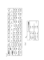
- FIG. 5A is a diagram showing an example of the actual statistical data Mk
- FIG. 5B is predicted statistical data M pC showing a prediction result of a road surface state to be described later.
- the predicted statistical data M pC is obtained by calculating the predicted value of the appearance ratio (hereinafter referred to as the predicted appearance ratio) S Rp for each road surface condition R at a future time t p (p> 0).
- the actual statistical data M k is created every time t k .
- the actual statistical data M k is usually created immediately after the estimated road surface state data at time t ⁇ 1, which is the time immediately before the time t p at which prediction is performed, is stored in the data storage unit 22.
- the actual statistical data storage unit 32 stores the actual statistical data M k created by the statistical data creation unit 31 in order of time.
- the predicted statistical data creation means 33 uses a plurality (in this case, ten) of actual statistical data M k arranged in time series shown in FIG. 5A, at a location L r within a predetermined range. Predictive statistical data M pC at a future time t p (p> 0) is created. Specifically, the time change of the appearance ratio S Rk whose estimated road surface state is R from time t ⁇ 10 to t ⁇ 1 is approximated by an n-order function G R (t) (n ⁇ 3), respectively.
- the prediction of the road surface condition R at time t p is made from these four function values G R (t p ).
- the appearance ratio S Rp is calculated, respectively, and the predicted statistical data M pC is created.
- Predicted appearance ratio S Rp is a function value G R (t p) of the road surface R, obtained by dividing the sum of the four function values G R (t p) ( ⁇ R G R (t p)).
- the road surface state predicting means 34 predicts which road surface state of the DRY road surface, the WET road surface, the SNOW road surface, and the ICE road surface will be the road surface state R. Specifically, in the predicted statistical data M pC , an estimated road surface state R (DRY road surface in FIG. 5B) having the highest predicted appearance rate S Rp is selected, and the selected road surface state is determined within a predetermined range. It is predicted that the road surface state R (t p ) at the time t p at the location L k in FIG. If the prediction of the road surface state is repeated using the prediction result of the road surface state, the road surface state R (t q ) at a future time t q (t q > t p ) can be predicted.
- step S10 vehicle information such as an estimated road surface state and a vehicle position is acquired (step S10), and the information is used together with vehicle ID and acquisition time data, It transmits to the server 20 of the road surface state management center 2 (step S11).
- the server 20 stores the estimated road surface state data and vehicle information for each predetermined location L r and in the order of the acquired time (step S12).
- the number of vehicles has been estimated to DRY road in place L r, the number of vehicles was estimated WET road, the number of vehicles was estimated SNOW road, and the number of vehicles was estimated to ICE road
- the time change of the appearance ratio S Rk in which the estimated road surface state is R from time t ⁇ n to t ⁇ 1 is After approximating the n-order function G R (t) (step S14), the function value G R (t p ), which is the value of the n-order function G R (t) at time t p, which is a future time, Then, from these four function values G R (t p ), a predicted appearance rate S Rp of the road surface condition R at time t p is obtained (step S15).
- the estimated road surface state R having the largest predicted appearance rate S Rp is predicted to be the road surface state R (t p ) at time t p (step S16). Finally, the determined road surface state information is transmitted to the registered vehicle. In the case of performing the prediction of the road surface condition different locations L r 'is the location L r is returned to step S13, continues the prediction of the road surface condition.
- the time variation of the road surface condition and the n-th order function G R (t) approximation has been calculated predicted appearance ratio S Rp road surface condition R at time t p, for example, every second time Even if the predicted appearance ratio S Rp of the road surface condition R is obtained using a time series filter such as a Kalman filter or a particle filter used when predicting a changing vehicle position from the output of the acceleration sensor or GPS data. Good. Further, in the first embodiment, the appearance ratio S in which the estimated road surface state from time t ⁇ 10 to t ⁇ 1 estimated by the road surface state estimation means 13 provided in each of the plurality of vehicles W i is R.
- the road surface estimated determination value K used in the estimation of the road surface condition R the determination value estimating means for estimating the k provided in each vehicle W i, from the road surface estimated determination value K k from time t -10 ⁇ t -1, obtains a predicted value K p of the road surface estimated determination value at time t p, From this predicted value K p , the road surface state R (t p ) at time t p may be predicted.
- the statistical data of the estimated road surface state is classified into four states of the DRY road surface, the WET road surface, the SNOW road surface, and the ICE road surface, but the SNOW road surface and the ICE road surface which are slippery road surfaces are collected. It is possible to determine the probability of occurrence of this dangerous road surface.
- Embodiment 2 the change in weather at the place where each vehicle is traveling is not taken into consideration.
- the road surface state prediction apparatus 30 described in FIG. 1 of the first embodiment A weather correction unit 35 is provided between the predicted statistical data creation unit 33 and the road surface state prediction unit 34, and the road surface state R (t p ) at the time t p predicted by the road surface state prediction unit 34 is is corrected based on the time t p of the weather forecast data at the location L r of a predetermined range, it is possible to further improve the prediction accuracy of the road surface condition.
- the weather correction means 35 includes a weather forecast data acquisition unit 35a, a weather model storage unit 35b, and a weather correction unit 35c.
- Weather forecast data acquisition unit 35a is connected to the drawing outside of the Internet, to get the forecast data of the weather and the temperature of the time zone including the time t p.
- the weather model storage unit 35b stores four weather models M R (R; DRY, WET, SNOW, ICE).
- FIGS. 8A to 8D are diagrams showing an example of the weather model M R , and each axis represents temperature (° C.), weather (1; clear, 2; cloudy, 3; rain, 4; snow, respectively. ),
- the weather model M R is created using past weather conditions and road surface data at a predetermined location L r . It is also possible to create a weather model M R for each season or each month. In this example, the weather is four and the temperature is ⁇ 10 ° C. to 10 ° C., however, the weather may be further classified, or the temperature range and the scale interval may be changed.
- Weather correction unit 35c from the weather model based on the forecast data of the weather m and temperature T of the time zone including the time t p obtained in weather forecast data acquisition unit 35a, are stored in the weather model storage unit 35b, weather Data of occurrence frequency P TmD , P TmW , P TmS , P TmI when m is temperature T and generation of predicted statistical data using these occurrence frequencies P TmD , P TmW , P TmS , P TmI
- the predicted appearance rate S Rp of the road surface condition R calculated by the means 33 is corrected. Specifically, as shown in FIG.
- S Spz P TmS ⁇ S Sp of SNOW road
- S Rpz P TmI ⁇ S Ip S.
- the road surface state having the largest corrected predicted value is the road surface state R z (t p ) at the time t p at the location L k within the predetermined range. Predict. If the prediction of the road surface state is repeated using the prediction result of the road surface state, the road surface state R z (t q ) in consideration of the weather at a future time t q (t q > t p ) is further predicted. can do.
- Embodiment 3 the occurrence frequency P TmD , P TmW , P TmS , P TmI when the weather is m and the temperature T is used to correct the predicted appearance rate S Rp of the road surface condition R, thereby correcting the weather.
- the road surface condition R z (t p ) in consideration of the above is predicted, but as shown in FIG. 11, the predicted statistical data creation means 33 of the road surface condition prediction apparatus 30 described in FIG.
- the weather correcting unit 35 the reference map M R0 for each road surface state (R; DRY road, WET road, SNOW road, ICE road) and the map storage means 36 that stores the reference map M R0 for each road surface condition
- a degree-of-fit calculation means 37 for calculating the degree of fit J of the predicted appearance ratio S Rp of the road surface condition R created by the forecast statistical data creation means 33, and is calculated in place of the weather correction unit 35c.
- the reference map M D0 of the DRY road surface is statistical data of an estimated road surface state obtained by running a test vehicle with standard tires on the DRY road surface many times at a constant speed.
- the ratio P DD0 estimated that the road surface is the DRY road surface the ratio P DW0 estimated that the road surface is the WET road surface
- the ratio P DS0 estimated that the road surface is the SNOW road surface the road surface Is a map of the ratio PDI0 estimated to be the ICE road surface.
- the reference map M W0 of WET road surface when the test vehicle traveled the WET road, the ratio P WD0 the road surface is estimated to be DRY road, the ratio P WW0 the road surface is estimated to be WET road , The ratio P WS0 estimated that the road surface is a SNOW road surface and the ratio P WI0 estimated that the road surface is an ICE road surface are mapped.
- the SNOW road surface reference map M S0 indicates that the test vehicle is SNOW.
- the reference map M I0 of the ICE road surface includes the ratio P ID0 that the road surface is estimated to be the DRY road surface when the test vehicle travels on the ICE road surface, the ratio P IW0 that the road surface is estimated to be the WET road surface, the road surface There proportion P IS0 estimated to be SNOW road, in which the road surface has mapped the ratio P ii0 estimated to be ICE road.
- the reference map M D0 has the highest P DD0
- the reference map M W0 has the highest P WW0
- the reference map M S0 has the highest P SS0
- the reference map M I0 has the highest P II0 .
- the ratio P RR′0 is referred to as a reference appearance ratio.
- R and R ′ indicate any one of D, W, S, and I.
- the degree-of-fit calculation means 37 uses the reference maps M D0 to M I0 for each road surface to predict the predicted appearance rate S Rp that is the predicted statistical data M pC created by the predicted statistical data creating means 33.
- the degree of fitness J R (R; DRY, WET, SNOW, ICE) is calculated, and the calculated four fitness J R is sent to the weather probability adding unit 35 d of the weather correction means 35.
- the DRY fitness J D is calculated by using the predicted appearance rate S Rp in the predicted statistical data M pC and the reference appearance rates P DD0 , P DW0 , P DS0 , and P DI0 in the reference map M D0 described below. Calculated by (1).
- J W exp ⁇ (
- J S exp ⁇ (
- J I exp ⁇ (
- the weather probability adding unit 35d uses the product of the occurrence frequency P TmR when the weather is m and the temperature T and the fitness J R calculated by the fitness calculation means 37, and the weather is m and the temperature T.
- the appearance ratio S RpZ of the road surface condition at a certain time is calculated.
- the predicted appearance ratio S SPZ P TmS ⁇ J S of the SNOW road surface
- the value of the predicted appearance rate S RpZ of the road surface condition R when the weather is m and the temperature T is normalized so that the sum ( ⁇ R S RpZ ) is 1. Yes.
- the road surface state prediction means 34 the road surface state R Z at the time t p of the place L k within the predetermined range is the road surface state having the largest predicted value (predicted appearance rate S RpZ ) when the weather is m and the temperature T. Predict that (t p ). If the prediction of the road surface state is repeated using the prediction result of the road surface state, the road surface state R Z (t q ) considering the weather at a future time t q (t q > t p ) is predicted. can do.
- a weather model M RmT may be created, and the predicted appearance rate may be predicted from the predicted appearance rate S Rp of the road surface condition R created by the data creation means 33 and the road surface weather model M RmT .
- the estimated road surface state appearance ratio S Rk estimated for a plurality of vehicles W i is used at the time t p using the actual statistical data M k calculated for each road surface state R.
- predicted road surface state R (t p) the vehicle having passed through the predetermined location L r at time t k is, when it was one vehicle W x is the actual statistics M k at time t k can not create . Therefore, in this case, the reference map M R0 for each road surface state described in the third embodiment is used as the actual statistical data M k .
- the DRY road surface reference map M D0 is set as the actual statistical data M k at time t k .
- the reference map M D0 includes the ratio P DD0 that the road surface is estimated to be the DRY road surface when traveling on the DRY road surface, the ratio P DW0 that the road surface is estimated to be the WET road surface, and the road surface Since the ratio P DS0 estimated to be the SNOW road surface and the ratio P DI0 estimated to be the ICE road surface are mapped, the reference map M D0 can be used instead of the actual statistical data M k.
- the actual statistical data M k is closer to the actual value, so that the prediction accuracy of the road surface state can be sufficiently ensured.
- the vehicle has passed a predetermined location L r few base (e.g., less than ten) can be applied if it is.
- L r few base e.g., less than ten
- the reference map M Actual statistical data M k may be created from D 0 and the reference map M W0 .
- the reference map M R0 for each road surface state is created in advance, even if there are a small number of vehicles that have passed the predetermined location L r , the future road surface state can be accurately predicted. .
- a plurality of vehicles W i are used for predicting the road surface state.
- a plurality of vehicles W p are used. It is also possible to predict the road surface condition R r (t p ) at a plurality of predetermined locations L r by running the route including the predetermined location L r a plurality of times. That is, at time t a , t b , t c ,..., The estimated road surface condition at a predetermined location L r is predetermined at time t a + h , t b + h , t c + h ,.
- the estimated road surface condition at the location L r ′ is sent from the vehicle W p to the server 20.
- the estimated road surface state R changes as time t a , t b , t c ,... (A ⁇ b ⁇ c ⁇ 0) elapses. Therefore, if the estimated road surface state R estimated by the vehicle W p at the time t m (m> 0) is replaced with the reference map M R0 of the road surface R, and this is used as the actual statistical data M k , the first embodiment is described.
- the road surface condition at time t m can be predicted. Note that the reference map M R0 may be changed for each vehicle W p .
- the predicted appearance rate S Rp of the road surface state R (t p ) is predicted.
- the road surface state transition prediction unit 38 is provided, and the past data generated by the statistical data generation unit 31 Among them, the predicted appearance rate S Rp of the road surface state R (t p ) at the future time t p may be predicted from the data at the time t ⁇ 1 .
- the statistical data creation unit 31 uses the data stored in the data storage unit 22 of the server 20 to store the time within the predetermined range at L r and the time immediately before the time t p predicted by the time t.
- a map is created in which the appearance ratio of the estimated road surface state R estimated at t (r) ⁇ 1 is tabulated for each estimated road surface state R (R; DRY road surface, WET road surface, SNOW road surface, ICE road surface).
- the road surface state transition prediction unit 38 includes a transition model storage unit 38a and an appearance ratio predicted value calculation unit 38b. As shown in FIG. 14, the transition model storage unit 38a stores four transition models T R (R; DRY, WET, SNOW, ICE).
- Transition model T R are those road surface condition was R k at time t k, 'probability that a (hereinafter, the transition probability of) q R, R' road surface condition R at time t k + 1 represents the It is created for each road surface condition R.
- the DRY transition model T D shown in the middle upper part of the figure the probability q D the state of the DRY road continues, D is 0.7, as was DRY road becomes WET road transition probability q D, W Is 0.2, the transition probability q D, S in which the DRY road surface becomes the SNOW road surface is 0.05, and the transition probability q D, I in which the DRY road surface becomes the ICE road surface is 0.05. ing.
- transition probabilities q R, R are created using the past road surface state R data.
- the appearance rate predicted value calculation unit 38b corrects the appearance rate S R-1 whose estimated road surface state is R at time t ⁇ 1 using the transition probability q R, R ′ described above, and thus the appearance rate predicted value S Rpt. Is calculated.
- the appearance ratio predicted value S Rpt is calculated for each road surface state R.
- the appearance ratio predicted values S Dpt , S Wpt , S Spt , and S Ipt of each road surface condition R are calculated by the following equations (5) to (8), respectively.
- S Dpt S D-1 ⁇ q D, D + S W-1 ⁇ q W, D + S S-1 ⁇ q S, D + S I-1 ⁇ q I, D (5)
- S Wpt S D-1 ⁇ q D, W + S W-1 ⁇ q W, W + S S-1 ⁇ q S, W + S I-1 ⁇ q I, W (6)
- S Spt S D-1 ⁇ q D, S + S W-1 ⁇ q W, S + S S-1 ⁇ q S, S + S I-1 ⁇ q I, S (7)
- S Ipt S D-1 ⁇ q D, I + S W-1 ⁇ q W, I + S S-1 ⁇ q S, I + S I-1 ⁇ q I, I (8)
- these appearance ratio predicted value S Dpt, S Wpt, S Spt , S Ipt the largest road conditions, locations L k of a predetermined range, road surface condition at time
- the future time t p is determined from the road surface state transition probability q R, R ′ obtained in advance and the appearance rate S R-1 of the estimated road surface state R at time t ⁇ 1 as past data. Since the predicted appearance rate S Rpt of the road surface state R at (p> 0) is predicted, the road surface state R t (t p ) at the future time t p can be predicted with a simple configuration.
- the appearance ratio predicted values S Dpt , S Wpt , S Spt , and S Ipt are obtained using the transition probabilities q R, R ′ obtained in advance from past data.
- the denominator 3 is the number of road surface conditions R ′ other than the road surface condition R.
- the road surface state R (t p ) is predicted, the immediately preceding predicted appearance rate V R-1 that is the predicted appearance rate at time t ⁇ 1 , the transition probability q R, R ′ described in the fourth embodiment,
- a predicted appearance rate V Rp of the road surface condition R at a future time t p is obtained using the predicted appearance rate S Rp obtained in the form 1, and these appearance rate predicted values V Dp , V Wp , V Sp , and V Ip are used.
- the future road surface state can be predicted with higher accuracy.
- the procedure for obtaining the predicted appearance rate V Rp will be described with reference to FIG. Calculating the predicted appearance ratio V Rp is immediately before the predicted appearance ratio V Rn until time t -1, ising, V R- 2, V R-1 and (calculated), the actual statistics M -n, ising, M -2 and M- 1 are obtained. Note that the first immediately preceding predicted appearance rate V Rn is a set value. First, the product P R, R′p of the immediately preceding predicted appearance rate V R-1 and the transition probability q R, R ′ at time t ⁇ 1 is obtained (procedure 1).
- the actual statistical data M -n ..., M ⁇ 3 , M ⁇ 2 , M ⁇ at the time t ⁇ n ,..., T ⁇ 3 , t ⁇ 2 , t ⁇ 1 before the time t p.
- the predicted appearance rate S Rp at time t p is obtained (procedure 2). Note that the prediction method of the predicted appearance rate S Rk is the same as that in the first embodiment, and thus the description thereof is omitted.
- the time t p is “the last time t ⁇ 1 ”, the time t ⁇ 1 is the time t ⁇ 2 , Time t ⁇ n becomes time t ⁇ n ⁇ 1 (the past time increases by one).
- the product of the product P R, R′p and the predicted appearance rate S Rp is the predicted appearance rate V Rp of the road surface state R at the future time t p , but the predicted appearance rate S Rp
- the matching degree J Rp between the reference appearance rate P RR ′ and the predicted appearance rate S Rp in the reference map M R0 which is a model corresponding to each road surface condition may be used.
- the goodness of fit J Rp is calculated by the following equation (9) as in the case of the third embodiment.
- the predicted appearance rate S Rp obtained in the first embodiment is used as the predicted appearance rate.
- a transition model TRT is created for each weather forecast data, or for each weather and temperature, and the transition model TRT and the immediately preceding predicted appearance rate V R are created.
- -1 using the predicted appearance ratio S Rp, may be obtained prediction appearance ratio V Rp road surface condition R at a future time t p.
- the predicted appearance rate S Rpt of the road surface state R (t p ) at the future time t p is determined from the transition model T R obtained in advance and the appearance rate S R-1 at the time t ⁇ 1 .
- the transition after the change U D, R is normalized so that the sum of the probabilities becomes 1.
- the above operation is also performed for the other transition models T W , T S , and T I to change the transition model T R.
- the transition model after the change and U R, to 'the probability of transition to the u R, R "road surface condition from R R and.
- the appearance ratio S R-1 at which the estimated road surface state at time t ⁇ 1 is R is corrected using the transition probability u R, R ′ to calculate the appearance ratio predicted value S RpT .
- a formula for calculating the appearance ratio predicted value S RpT is shown in the following formula (10).
- S RpT S D-1 ⁇ u D, R + S W-1 ⁇ u W, R + S S-1 ⁇ u S, R + S I-1 ⁇ u I, R (10)
- the appearance ratio predicted value S RpT is calculated for each road surface state R.
- the transition of the road surface state probability q R, the R ', since the change in response to the transition state of the historical data (actual statistical data M k) the road surface condition R t at a future time t p (t p ) Prediction accuracy can be further improved.
- transition model T R Change rate v Rm ,..., V R-2 , v R-1 of the appearance ratio at a plurality of consecutive times t ⁇ m ,..., T ⁇ 3 , t ⁇ 2 before time t ⁇ 1. It may change the transition model T R with.
- the appearance rate of change rate v Rm, ??, v R-2, v such as the R-1 average value or appearance ratio at time t p the linear combination of the rate of change v Rp, appearance ratio of the rate of change v
- the change rate v Rp of the appearance ratio at the time t p may be obtained using an arithmetic expression of Rk .
- appearance ratio S R-1 and the transition probability u R at time t -1 was calculated appearance ratio predicted value S RPT by using the R ', predicted occurrence at time t -1
- the road surface condition may be predicted using the immediately preceding prediction ratio V R-1 that is the ratio and the transition probability u R, R ′ .
- the transition probabilities u R, R ′ may be changed according to information such as the topography and the weather and temperature provided as the weather forecast.
- the statistical data of the estimated road surface state is not limited to obtaining the four states of the DRY road surface, the WET road surface, the SNOW road surface, and the ICE road surface, and is based on the road surface friction coefficient ⁇ . Divided into “high ⁇ road ( ⁇ ⁇ 0.7)”, “medium ⁇ road (0.3 ⁇ ⁇ 0.7)”, “low ⁇ road ( ⁇ ⁇ 0.3)”, etc. Good.
- the estimated road conditions from time t -10 ⁇ t -1 is R emergence from the time variation of the ratio S Rk, the time has been determined the prediction value S Rp occurrence rate of the road surface state R in t p, instead of the road surface condition estimation unit 13, the road surface estimated determination value K used in the estimation of the road surface condition R the provided determination value estimation means for estimating the respective vehicle W i, from the road surface estimated determination value K k from time t -10 ⁇ t -1, obtains a predicted value K p of the road surface estimated determination value at time t p, the The road surface state R p at time t p may be predicted from the predicted value K p .
- the road surface condition estimating means 13 is provided for each vehicle W i
- the road surface condition estimating means 13 provided in the road surface condition management center 2 from the vehicle W i is provided for each vehicle W i May be configured to send a plurality of band values (vibration levels in a specific frequency band detected from the acceleration waveform) used for estimating the road surface condition, or a calculated value of the band value to the road surface state management center 2.
- band values vibration levels in a specific frequency band detected from the acceleration waveform
- the road surface state estimating means 13 estimates whether the road surface state is a DRY road surface, a WET road surface, a SNOW road surface, or an ICE road surface from the value of an identification function using a kernel function.
- the vibration level of the vibration spectrum obtained by frequency analysis of the time series waveform of the acceleration detected by the acceleration sensor 11, the road surface friction coefficient ⁇ and the vibration level determined in advance are used.
- a road surface state estimation device configured to estimate the road surface friction coefficient ⁇ by comparing with a G-table indicating the relationship between the road surface and a road surface state from a time series waveform of an acceleration sensor attached to a tire or a rim.
- Road surface state estimation means having other configurations such as a road surface state estimation device may be used.
- Road surface state estimating means configured to estimate whether the road is a wet asphalt road, a slightly wet asphalt road, a dry asphalt road, or an ice road may be used.
- a road surface state prediction method is calculated using a vehicle sensor mounted on a vehicle to obtain vehicle information that is information on the behavior of the vehicle during travel, and the vehicle information.
- Road surface estimation determination value used for estimation of road surface state, or a road surface comprising a step of predicting a road surface state of a place within a predetermined range using the estimated road surface state estimated using the road surface estimation determination value
- a time change or estimation of a road surface estimation determination value calculated using vehicle information acquired by a vehicle that has passed a place within a predetermined range.
- the road surface state at a place within a predetermined range to be predicted refers to a future road surface state R (t p ) that is a road surface state at time t p (p> 0) that is the current time t.
- road surface estimated determination value at time t k (or estimated road surface condition) is within the time width including the time t k is Delta] t k of time (e.g., t k - ⁇ t k / 2 ⁇ t ⁇ t k + ⁇ t k / 2) indicates the road surface estimation determination value (or estimated road surface state) acquired.
- the road surface estimation judgment value at a plurality of times acquired at a location within the predetermined range or the estimated road surface state with time is predicted to predict the future road surface state at the location within the predetermined range.
- the future road surface condition can be accurately predicted.
- the predicted appearance ratio S Rp of the road surface state in the predicted predetermined range is set to the estimated road surface state transition probability q ′ RR ′ set in advance.
- the transition probability q RR ′ of the estimated road surface state obtained in advance and the immediately preceding appearance rate V R-1 that is the predicted appearance rate at time t ⁇ 1 before the time t p for predicting the road surface state are obtained.
- the appearance ratio predicted value V Rp which is a correction value of the predicted appearance ratio S Rp , is calculated.
- the preset estimated road surface state transition probability q ′ RR ′ or the estimated road surface state transition probability q RR ′ obtained in advance, and the immediately preceding appearance ratio V R ⁇ 1 already calculated. If the predicted appearance rate S Rp at a location within the predetermined range is corrected using, the future road surface condition can be accurately predicted.
- the road surface state prediction method includes a step of obtaining vehicle information, which is information on the behavior of the vehicle during traveling, by an in-vehicle sensor mounted on the vehicle, and an operation using the vehicle information. Predicting a road surface state of a place within a predetermined range using a road surface estimation determination value used for estimation of a road surface state or an estimated road surface state estimated using the road surface estimation determination value.
- vehicle information which is information on the behavior of the vehicle during traveling
- an in-vehicle sensor mounted on the vehicle Predicting a road surface state of a place within a predetermined range using a road surface estimation determination value used for estimation of a road surface state or an estimated road surface state estimated using the road surface estimation determination value.
- an estimated road surface state estimated using vehicle information acquired by a vehicle that has passed a place within a predetermined range is set in advance.
- the road surface state at time t p is predicted using the preset transition probability q ′ RR ′ of the estimated road surface state or the transition probability q RR ′ of the estimated road surface state obtained in advance.
- the road surface condition at time t p can be easily predicted.
- the road surface state prediction method according to one aspect of the present invention may be configured such that the preset estimated road surface state transition probability q ′ RR ′ or the previously calculated estimated road surface state transition probability is calculated as the road surface state.
- the predicted road surface condition R (t p ) is corrected based on weather forecast information such as weather, temperature, rainfall, wind speed, and sunshine duration.
- weather forecast information such as weather, temperature, rainfall, wind speed, and sunshine duration.
- “correcting” predicts whether or not the predicted road surface state changes according to information such as weather and temperature provided as a weather forecast, and if it changes, which road surface state is predicted. Refers to that.
- the information used for the correction includes an estimation result of a road surface state at a location within another predetermined range. Specifically, in the past conditions (weather, traffic volume, road surface state estimation results, etc.), the road surface state estimation result of the location B in another predetermined range correlated with the location A within the predetermined range. It is possible to correct the estimation result at the location A within the predetermined range.
- the road surface state prediction method uses the predicted road surface state R (t p ), and a time t q (t q > t p ) further later than the predicted time t p.
- the road surface condition R (t q ) is predicted.
- it is possible to further predict the future road surface state by repeating the prediction of the road surface state again using the predicted result.
- the present invention it is possible to accurately determine and determine the road surface state at a location within the predetermined time and within the predetermined range. By notifying the traveling vehicle, the traveling safety of the vehicle can be improved.
- 1 Road surface condition prediction system 1 Road surface condition prediction system, 2 Road surface condition management center, W 1 to W N vehicle, 11 acceleration sensor, 12 GPS device, 13 road surface state estimating means, 14 vehicle information collecting means, 15 transmitter, 16 receivers, 20 servers, 21 receivers, 22 data storage means, 23 transmitter, 30 road surface state prediction device, 31 statistical data creation means, 32 discrimination result storage means, 33 prediction statistical data creation means, 34 road surface state prediction means, 35 weather correction means, 35a weather forecast data acquisition unit, 35b weather model storage unit, 35c weather correction unit, 36 predicted value correction means, 36a transition model storage unit, 36b appearance ratio predicted value calculation unit, 36c predicted value correction unit, 40 tires, 41 inner liner, 42 tire chamber, 43 treads, 44 rims.
Landscapes
- Physics & Mathematics (AREA)
- General Physics & Mathematics (AREA)
- Engineering & Computer Science (AREA)
- Chemical & Material Sciences (AREA)
- Analytical Chemistry (AREA)
- Transportation (AREA)
- Mechanical Engineering (AREA)
- Environmental & Geological Engineering (AREA)
- Remote Sensing (AREA)
- Radar, Positioning & Navigation (AREA)
- Life Sciences & Earth Sciences (AREA)
- Atmospheric Sciences (AREA)
- Biodiversity & Conservation Biology (AREA)
- Ecology (AREA)
- Environmental Sciences (AREA)
- Traffic Control Systems (AREA)
- Management, Administration, Business Operations System, And Electronic Commerce (AREA)
- Regulating Braking Force (AREA)
Abstract
所定の範囲内の場所における路面状態を精度よく予測する方法を提供するために、車両に搭載された車載センサにより取得された、走行時の車両Wiの挙動の情報である車両情報を用いて演算される、路面推定判定値、もしくは、前記路面推定判定値を用いて推定された推定路面状態を用いて、所定範囲内の場所の路面状態を予測する際に、所定の範囲内の場所において演算された路面推定判定値、もしくは、推定された推定路面状態の時間変化から、前記所定の範囲内の場所における路面状態を予測するようにした。
Description
本発明は、車両の走行する路面の状態を予測する方法に関するもので、特に、所定の範囲内の場所を走行する車両の推定した路面状態のデータや車両情報を用いて、路面状態を予測する方法に関する。
自動車の走行安全性を高めるため、走行中の路面の状態を精度良く推定し、車両制御へフィードバックすることが求められている。走行中の路面の状態を推定することができれば、制駆動や操舵といった危険回避の操作を起こす前に、例えば、ABSブレーキのより高度な制御等が可能になり、安全性が一段と高まることが予想される。
走行中の路面の状態を推定する方法としては、例えば、走行中のタイヤの振動を検出し、この検出されたタイヤの振動の時系列波形から路面状態を推定する方法(例えば、特許文献1~3参照)や、タイヤから発生するタイヤ発生音を検出し、この検出されたタイヤ発生音の音圧レベルから路面状態を推定する方法(例えば、特許文献4参照)が提案されている。
しかしながら、上記の従来技術では、走行中の路面状態については推定できるものの、路面状態の推定結果から所定の範囲内の場所における路面状態の変化を予測することは困難であった。
本発明は、従来の問題点に鑑みてなされたもので、所定の範囲内の場所における路面状態を精度よく予測する方法を提供することを目的とする。
本発明の一態様にかかる路面状態予測方法は、車両に搭載された車載センサにより、走行時の前記車両の挙動の情報である車両情報を取得するステップと、前記車両情報を用いて演算される、路面状態の推定に用いられる路面推定判定値、もしくは、前記路面推定判定値を用いて推定された推定路面状態を用いて、所定範囲内の場所の路面状態を予測するステップとを備えた路面状態予測方法であって、前記路面状態を予測するステップでは、所定の範囲内の場所を通過した車両にて取得された車両情報を用いて演算された路面推定判定値の時間変化、もしくは、推定路面状態の時間変化から、前記所定の範囲内の場所における路面状態の出現割合である路面状態毎の予測出現割合SRpを算出した後、前記算出された予測出現割合SRpから、前記所定の範囲内の場所における路面状態を予測することを特徴とする。
実施の形態1.
図1は、本実施の形態1に係る路面状態予測システム1の構成を示す機能ブロック図で、W1~WNは車両で、各車両Wi(i=1~N)は、車載センサとしての加速度センサ11と、GPS装置12と、路面状態推定手段13と、車両情報収集手段14と、送信機15と、受信機16とを備える。
20は受信機21と、データ記憶手段22と、送信機23とを備えたサーバーで、30は所定の範囲内の場所において複数の時刻に複数の車両Wiにてそれぞれ推定された推定路面状態の時間変化から、所定の範囲内の場所における路面の状態を予測する路面状態予測装置である。
なお、「車両数N」は、「のべ車両数」で、1台の車両の、所定の時間内かつ所定の範囲内の場所おけるデータが複数個である場合には、これら複数のデータを別個のデータとして処理する。
サーバー20と路面状態予測装置30とは、路面状態管理センター2に設けられる。
路面状態推定手段13、車両情報収集手段14、及び、路面状態予測装置30は、例えば、コンピュータのソフトウェアにより構成される。
加速度センサ11は、図2に示すように、タイヤ40のインナーライナー部41のタイヤ気室42側のほぼ中央部に配置されて、路面Rからタイヤ40のトレッド43に入力する振動(タイヤ振動)を検出する。
図1は、本実施の形態1に係る路面状態予測システム1の構成を示す機能ブロック図で、W1~WNは車両で、各車両Wi(i=1~N)は、車載センサとしての加速度センサ11と、GPS装置12と、路面状態推定手段13と、車両情報収集手段14と、送信機15と、受信機16とを備える。
20は受信機21と、データ記憶手段22と、送信機23とを備えたサーバーで、30は所定の範囲内の場所において複数の時刻に複数の車両Wiにてそれぞれ推定された推定路面状態の時間変化から、所定の範囲内の場所における路面の状態を予測する路面状態予測装置である。
なお、「車両数N」は、「のべ車両数」で、1台の車両の、所定の時間内かつ所定の範囲内の場所おけるデータが複数個である場合には、これら複数のデータを別個のデータとして処理する。
サーバー20と路面状態予測装置30とは、路面状態管理センター2に設けられる。
路面状態推定手段13、車両情報収集手段14、及び、路面状態予測装置30は、例えば、コンピュータのソフトウェアにより構成される。
加速度センサ11は、図2に示すように、タイヤ40のインナーライナー部41のタイヤ気室42側のほぼ中央部に配置されて、路面Rからタイヤ40のトレッド43に入力する振動(タイヤ振動)を検出する。
GPS装置12は、図示しないGPSアンテナと受信機とを備え、当該車両Wiの位置データを取得するとともに、車両の位置データから当該車両の走行速度を算出する。
路面状態推定手段13は、加速度センサ11で検出したタイヤ振動の時系列波形を用いて、走行中の路面が、DRY路面,WET路面,SNOW路面,ICE路面のいずれかであるかを推定する。このような、路面状態推定手段13としては、例えば、図3(a)に示すような、加速度センサ11からタイヤ振動の時系列波形を抽出する振動波形抽出手段131と、窓掛け手段132と、特徴ベクトル算出手段133と、4つの路面モデルを記憶する記憶手段134と、カーネル関数算出手段135と、路面状態判別手段136とを備え、図3(b)に示すような、タイヤ振動の時系列波形に所定の時間幅Tの窓関数をかけて抽出した時間窓毎の時系列波形から、それぞれ、複数の特定周波数帯域の振動レベル(ak1~akm)を成分とした特徴ベクトルXk(ak1,ak2,……,akm)を算出し、これらの特徴ベクトルと予め求めておいた路面状態毎の特徴ベクトルとからカーネル関数を算出し、このカーネル関数を用いた識別関数の値から路面状態がDRY路面,WET路面,SNOW路面,ICE路面のいずれかであるかを推定する構成の路面状態判別装置13Kなどが挙げられる。なお、路面状態毎の特徴ベクトルは、試験車両をDRY路面,WET路面,SNOW路面,ICE路面上でそれぞれ走行させたときの複数の特定周波数帯域の振動レベルを成分とした特徴ベクトルである。
なお、路面状態推定手段13はタイヤ内40に設けてもよいし、車体側に設けてもよい。車体側に設ける場合には、タイヤ40側から加速度センサで検出した加速度波形のデータを車体側に送るのではなく、タイヤ40側に演算装置を設けて、加速度波形から検出される特定周波数帯域の振動レベルなどの路面状態の推定に用いる帯域値、もしくは、帯域値の演算値を算出し、これを路面状態推定手段13に送る構成とすることが好ましい。
路面状態推定手段13は、加速度センサ11で検出したタイヤ振動の時系列波形を用いて、走行中の路面が、DRY路面,WET路面,SNOW路面,ICE路面のいずれかであるかを推定する。このような、路面状態推定手段13としては、例えば、図3(a)に示すような、加速度センサ11からタイヤ振動の時系列波形を抽出する振動波形抽出手段131と、窓掛け手段132と、特徴ベクトル算出手段133と、4つの路面モデルを記憶する記憶手段134と、カーネル関数算出手段135と、路面状態判別手段136とを備え、図3(b)に示すような、タイヤ振動の時系列波形に所定の時間幅Tの窓関数をかけて抽出した時間窓毎の時系列波形から、それぞれ、複数の特定周波数帯域の振動レベル(ak1~akm)を成分とした特徴ベクトルXk(ak1,ak2,……,akm)を算出し、これらの特徴ベクトルと予め求めておいた路面状態毎の特徴ベクトルとからカーネル関数を算出し、このカーネル関数を用いた識別関数の値から路面状態がDRY路面,WET路面,SNOW路面,ICE路面のいずれかであるかを推定する構成の路面状態判別装置13Kなどが挙げられる。なお、路面状態毎の特徴ベクトルは、試験車両をDRY路面,WET路面,SNOW路面,ICE路面上でそれぞれ走行させたときの複数の特定周波数帯域の振動レベルを成分とした特徴ベクトルである。
なお、路面状態推定手段13はタイヤ内40に設けてもよいし、車体側に設けてもよい。車体側に設ける場合には、タイヤ40側から加速度センサで検出した加速度波形のデータを車体側に送るのではなく、タイヤ40側に演算装置を設けて、加速度波形から検出される特定周波数帯域の振動レベルなどの路面状態の推定に用いる帯域値、もしくは、帯域値の演算値を算出し、これを路面状態推定手段13に送る構成とすることが好ましい。
車両情報収集手段14は、路面状態推定手段13で推定された路面状態(以下、推定路面状態という)と、GPS装置12で取得した車両の位置データとを収集して、当該車両を識別するための車両IDとともに、当該車両の車両情報として、送信機15に送る。車両情報には、車両IDと車両情報の取得時刻のデータ(時刻データ)も含まれる。なお、時刻データとしては、加速度の時系列波形の抽出時刻、位置データの取得時刻あるいは、データ送信時刻などを用いればよい。これらの時刻は、ほほ同時刻なので、どの時刻を時刻データとしても問題はない。
送信機15は、前記車両情報を、車両情報収集手段14により収集された、推定路面状態のデータ、車両の位置データ、及び、当該車両を識別するための車両IDとともに、図示しない送信アンテナから、車両情報として、路面状態管理センター2のサーバー20に送信する。
受信機16は、路面状態管理センター2の路面状態予測装置30で予測され、サーバー20の送信機から送信された所定の範囲内の場所における路面状態の予測データを受信する。なお、この受信された路面状態の予測データを、車内に設けられたモニター上に表示することで、運転者は、所定の範囲内の場所における路面状態の予測結果を知ることができる。
また、路面状態の予測結果を車両制御へフィードバックすれば、車両の走行安全性を向上させることができる。
送信機15は、前記車両情報を、車両情報収集手段14により収集された、推定路面状態のデータ、車両の位置データ、及び、当該車両を識別するための車両IDとともに、図示しない送信アンテナから、車両情報として、路面状態管理センター2のサーバー20に送信する。
受信機16は、路面状態管理センター2の路面状態予測装置30で予測され、サーバー20の送信機から送信された所定の範囲内の場所における路面状態の予測データを受信する。なお、この受信された路面状態の予測データを、車内に設けられたモニター上に表示することで、運転者は、所定の範囲内の場所における路面状態の予測結果を知ることができる。
また、路面状態の予測結果を車両制御へフィードバックすれば、車両の走行安全性を向上させることができる。
サーバー20は、各車両Wi(i=1~N)から送られてくる推定路面状態のデータを含む車両情報を受信機21で受信し、これらのデータを、所定の範囲内の場所における各時刻毎のデータに分類して、データ記憶手段22に保存するとともに、送信機23から、路面状態予測装置30で予測された所定の範囲内の場所における路面状態の予測データを登録車両に送信する。
各車両Wiの車両情報は、データ記憶手段22に分類・保存される。
具体的には、図4に示すように、データ記憶手段22の記憶領域221には、所定の場所L1において、複数の時刻t(1)k(t-n1~t-1)に複数の車両W(1)j(j=1~m1)でそれぞれ取得されたデータが保存され、記憶領域222には、所定の場所L2において複数の時刻t(2)k(k=-n2~-1)に、複数の車両W(2)j(j=1~m2)で取得されたデータが保存される。このように、記憶領域22rには、所定の場所Lrにおいて複数の時刻t(r)k(k=-nr~-1)に複数の車両W(r)j(j=1~mr)で取得されたデータが保存される。
ここで、m1+m2+……+mr+……=Nである。なお、データを取得する時刻の数nrについては、各場所Lrにより異なっていてもよいし、同じであってもよい。
各所定の場所Lrにおけるデータは、時間順に保存される。
なお、時刻tkにおけるデータとは、時刻tkを含む所定の時間幅がΔtkの時間内(例えば、tk-Δtk/2≦t≦tk+Δtk/2)に取得したデータを指す。所定の時間幅Δtkは、必ずしも一定にする必要はなく、例えば、所定の場所により変更してもよい。
所定の時間幅Δtkとしては、例えば、1分~5分以内が想定される。また、所定の範囲とは、予め設定された道路地図上の場所を含む範囲を指す。所定の範囲の指定は、例えば、図4に示す、ナビゲーション用の道路地図上の所定大きさ枠のグリットを用いればよい。このようにすれば、各車両Wi、詳細には、車両W(r)jとサーバー20とにおける車両位置の整合性を取り易いので好ましい。
また、登録車両は、前記の路面状態推定手段13を搭載した車両Wiだけではなく、サーバー20と通信により接続されている車両も含まれる。
各車両Wiの車両情報は、データ記憶手段22に分類・保存される。
具体的には、図4に示すように、データ記憶手段22の記憶領域221には、所定の場所L1において、複数の時刻t(1)k(t-n1~t-1)に複数の車両W(1)j(j=1~m1)でそれぞれ取得されたデータが保存され、記憶領域222には、所定の場所L2において複数の時刻t(2)k(k=-n2~-1)に、複数の車両W(2)j(j=1~m2)で取得されたデータが保存される。このように、記憶領域22rには、所定の場所Lrにおいて複数の時刻t(r)k(k=-nr~-1)に複数の車両W(r)j(j=1~mr)で取得されたデータが保存される。
ここで、m1+m2+……+mr+……=Nである。なお、データを取得する時刻の数nrについては、各場所Lrにより異なっていてもよいし、同じであってもよい。
各所定の場所Lrにおけるデータは、時間順に保存される。
なお、時刻tkにおけるデータとは、時刻tkを含む所定の時間幅がΔtkの時間内(例えば、tk-Δtk/2≦t≦tk+Δtk/2)に取得したデータを指す。所定の時間幅Δtkは、必ずしも一定にする必要はなく、例えば、所定の場所により変更してもよい。
所定の時間幅Δtkとしては、例えば、1分~5分以内が想定される。また、所定の範囲とは、予め設定された道路地図上の場所を含む範囲を指す。所定の範囲の指定は、例えば、図4に示す、ナビゲーション用の道路地図上の所定大きさ枠のグリットを用いればよい。このようにすれば、各車両Wi、詳細には、車両W(r)jとサーバー20とにおける車両位置の整合性を取り易いので好ましい。
また、登録車両は、前記の路面状態推定手段13を搭載した車両Wiだけではなく、サーバー20と通信により接続されている車両も含まれる。
路面状態予測装置30は、統計データ作成手段31と、実統計データ記憶手段32と、予測統計データ作成手段33と、路面状態予測手段34とを備え、時刻t-n~時刻t-1にて取得した車両情報を用いて、所定の範囲内の場所Lrにおける、将来の時刻tp(p>0)における路面状態を予測する。
統計データ作成手段31では、サーバー20のデータ記憶手段22に保存されたデータから、所定の範囲内の場所Lrにて、現在の時刻t0よりも前の時刻t(r)k(k=-n1~-1)に取得したmr個の推定路面状態のデータを取り出した後、これらのデータを用いて、DRY路面と推定した車両数、WET路面と推定した車両数,SNOW路面と推定した車両数、及び、ICE路面と推定した車両数がそれぞれ何個あるかをカウントして、所定の範囲内の場所Lrの時刻t(r)kにおける推定路面状態Rの出現割合を、推定路面状態R(R;DRY路面,WET路面,SNOW路面,ICE路面)毎に集計したマップ(以下、実統計データM(r)kという)を作成する。なお、1台の車両が、所定の時間内かつ所定の範囲内の場所において複数のデータを送ってくる場合には、別車両からのデータとして処理する。この場合、車両数は「のべ車両数」となる。なお、データが同一車両のデータであるか否かは車両IDにより区別できる。
路面状態の予測は場所Lr毎に行うが、以下では、場所Lrにおける路面状態を予測する場合について説明する。なお、場所Lrを時刻tkに通過する車両をWj(j=1~m)、実統計データをMkとするなど、以下では、場所Lrを示す添字rを省略する。
統計データ作成手段31では、サーバー20のデータ記憶手段22に保存されたデータから、所定の範囲内の場所Lrにて、現在の時刻t0よりも前の時刻t(r)k(k=-n1~-1)に取得したmr個の推定路面状態のデータを取り出した後、これらのデータを用いて、DRY路面と推定した車両数、WET路面と推定した車両数,SNOW路面と推定した車両数、及び、ICE路面と推定した車両数がそれぞれ何個あるかをカウントして、所定の範囲内の場所Lrの時刻t(r)kにおける推定路面状態Rの出現割合を、推定路面状態R(R;DRY路面,WET路面,SNOW路面,ICE路面)毎に集計したマップ(以下、実統計データM(r)kという)を作成する。なお、1台の車両が、所定の時間内かつ所定の範囲内の場所において複数のデータを送ってくる場合には、別車両からのデータとして処理する。この場合、車両数は「のべ車両数」となる。なお、データが同一車両のデータであるか否かは車両IDにより区別できる。
路面状態の予測は場所Lr毎に行うが、以下では、場所Lrにおける路面状態を予測する場合について説明する。なお、場所Lrを時刻tkに通過する車両をWj(j=1~m)、実統計データをMkとするなど、以下では、場所Lrを示す添字rを省略する。
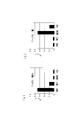
図5(a)は実統計データMkの一例を示す図で、図5(b)は、後述する路面状態の予測結果を示す予測統計データMpCである。
実統計データMkは、時刻tk(k=-n~-1)における推定路面状態R(R;DRY,WET,SNOW,ICE)の出現割合SRkを路面状態R毎に算出したもので、予測統計データMpCは、将来の時刻tp(p>0)おける出現割合の予測値(以下、予測出現割合という)SRpを路面状態R毎に算出したものである。
出現割合SRkは、SRk=(推定路面状態Rのカウント数)/(総カウント数)により算出される。なお、実統計データMkは時刻tk毎に作成される。
実統計データMkの作成は、通常、データ記憶手段22に、予測を行う時刻tpの直前の時刻である時刻t-1における推定路面状態のデータが保存された直後に行う。
実統計データ記憶手段32は、統計データ作成手段31で作成された実統計データMkを、時間順に保存する。
実統計データMkは、時刻tk(k=-n~-1)における推定路面状態R(R;DRY,WET,SNOW,ICE)の出現割合SRkを路面状態R毎に算出したもので、予測統計データMpCは、将来の時刻tp(p>0)おける出現割合の予測値(以下、予測出現割合という)SRpを路面状態R毎に算出したものである。
出現割合SRkは、SRk=(推定路面状態Rのカウント数)/(総カウント数)により算出される。なお、実統計データMkは時刻tk毎に作成される。
実統計データMkの作成は、通常、データ記憶手段22に、予測を行う時刻tpの直前の時刻である時刻t-1における推定路面状態のデータが保存された直後に行う。
実統計データ記憶手段32は、統計データ作成手段31で作成された実統計データMkを、時間順に保存する。
予測統計データ作成手段33は、図5(a)に示す、時系列に配列された複数個(ここでは、10個)の実統計データMkを用いて、所定の範囲内の場所Lrにおける将来の時刻tp(p>0)における予測統計データMpCを作成する。
具体的には、時刻t-10~t-1までの推定路面状態がRである出現割合SRkの時間変化を、それぞれ、n次関数GR(t)(n≧3)で近似し、t=tpにおける近似関数(n次関数)の関数値GR(tp)をそれぞれ求めた後、これらの4つの関数値GR(tp)から、時刻tpにおける路面状態Rの予測出現割合SRpをそれぞれ算出して、予測統計データMpCを作成する。
予測出現割合SRpは、各路面Rの関数値GR(tp)を、4つの関数値GR(tp)の和(ΣRGR(tp))で除算して求められる。
すなわち、DRY路面の予測出現割合はSDp=GD(tp)/ΣRGR(tp)により算出され、WET路面の予測出現割合はSWp=GW(tp)/ΣRGR(tp)により算出される。また、SNOW路面の予測出現割合SSp=GS(tp)/ΣRGR(tp)により算出され、ICE路面の予測出現割合はSIp=GI(tp)/ΣRGR(tp)によりそれぞれ算出される。予測出現割合SDp,SWp,SSp,SIpの総和は1である。
路面状態の予測結果を示す予測統計データMpCの一例を図5(b)に示す。
路面状態予測手段34は、路面状態RがDRY路面,WET路面,SNOW路面,ICE路面の内のいずれの路面状態になるかを予測する。具体的には、予測統計データMpCにおいて、予測出現割合SRpが最も高い推定路面状態R(図5(b)では、DRY路面)を選択し、この選択された路面状態を、所定の範囲内の場所Lkの、時刻tpにおける路面状態R(tp)であると予測する。
このような路面状態の予測結果を使って、路面状態の予測を繰り返せば、更に将来の時刻tq(tq>tp)での路面状態R(tq)を予測することができる。
具体的には、時刻t-10~t-1までの推定路面状態がRである出現割合SRkの時間変化を、それぞれ、n次関数GR(t)(n≧3)で近似し、t=tpにおける近似関数(n次関数)の関数値GR(tp)をそれぞれ求めた後、これらの4つの関数値GR(tp)から、時刻tpにおける路面状態Rの予測出現割合SRpをそれぞれ算出して、予測統計データMpCを作成する。
予測出現割合SRpは、各路面Rの関数値GR(tp)を、4つの関数値GR(tp)の和(ΣRGR(tp))で除算して求められる。
すなわち、DRY路面の予測出現割合はSDp=GD(tp)/ΣRGR(tp)により算出され、WET路面の予測出現割合はSWp=GW(tp)/ΣRGR(tp)により算出される。また、SNOW路面の予測出現割合SSp=GS(tp)/ΣRGR(tp)により算出され、ICE路面の予測出現割合はSIp=GI(tp)/ΣRGR(tp)によりそれぞれ算出される。予測出現割合SDp,SWp,SSp,SIpの総和は1である。
路面状態の予測結果を示す予測統計データMpCの一例を図5(b)に示す。
路面状態予測手段34は、路面状態RがDRY路面,WET路面,SNOW路面,ICE路面の内のいずれの路面状態になるかを予測する。具体的には、予測統計データMpCにおいて、予測出現割合SRpが最も高い推定路面状態R(図5(b)では、DRY路面)を選択し、この選択された路面状態を、所定の範囲内の場所Lkの、時刻tpにおける路面状態R(tp)であると予測する。
このような路面状態の予測結果を使って、路面状態の予測を繰り返せば、更に将来の時刻tq(tq>tp)での路面状態R(tq)を予測することができる。
次に、路面状態予測システム1の動作について、図6のフローチャートを参照して説明する。
まず、各車両Wi(i=1~N)にて、推定路面状態、及び、車両位置などの車両情報を取得し(ステップS10)、これらの情報を、車両ID及び取得時刻のデータとともに、路面状態管理センター2のサーバー20に送信する(ステップS11)。
次に、サーバー20にて、推定路面状態のデータ及び車両情報を、所定の場所Lr毎に、かつ、取得した時刻順に保存(ステップS12)する。
そして、統計データ作成手段31にて、所定の場所LrにおいてDRY路面と推定した車両数、WET路面と推定した車両数,SNOW路面と推定した車両数,及び、ICE路面と推定した車両数をカウントした統計データである実統計データMkを、各時刻tk(k=-n~-1)毎に作成し、これを時系列に配列する(ステップS13)。
次に、時系列に配列された各時刻tk毎の実統計データMkを用いて、時刻t-n~t-1までの推定路面状態がRである出現割合SRkの時間変化を、それぞれ、n次関数GR(t)近似し(ステップS14)た後、将来の時刻である時刻tpにおけるn次関数GR(t)の値である関数値GR(tp)をそれぞれ求め、これらの4つの関数値GR(tp)から、時刻tpにおける路面状態Rの予測出現割合SRpを求める(ステップS15)。
そして、予測出現割合SRpの値が最も大きい推定路面状態Rを、時刻tpにおける路面状態R(tp)であると予測する(ステップS16)。
最後に、判別した路面状態の情報を、登録車両に送信する。
なお、場所Lrとは異なる場所Lr’の路面状態の予測を行う場合には、ステップS13に戻って、路面状態の予測を続行する。
まず、各車両Wi(i=1~N)にて、推定路面状態、及び、車両位置などの車両情報を取得し(ステップS10)、これらの情報を、車両ID及び取得時刻のデータとともに、路面状態管理センター2のサーバー20に送信する(ステップS11)。
次に、サーバー20にて、推定路面状態のデータ及び車両情報を、所定の場所Lr毎に、かつ、取得した時刻順に保存(ステップS12)する。
そして、統計データ作成手段31にて、所定の場所LrにおいてDRY路面と推定した車両数、WET路面と推定した車両数,SNOW路面と推定した車両数,及び、ICE路面と推定した車両数をカウントした統計データである実統計データMkを、各時刻tk(k=-n~-1)毎に作成し、これを時系列に配列する(ステップS13)。
次に、時系列に配列された各時刻tk毎の実統計データMkを用いて、時刻t-n~t-1までの推定路面状態がRである出現割合SRkの時間変化を、それぞれ、n次関数GR(t)近似し(ステップS14)た後、将来の時刻である時刻tpにおけるn次関数GR(t)の値である関数値GR(tp)をそれぞれ求め、これらの4つの関数値GR(tp)から、時刻tpにおける路面状態Rの予測出現割合SRpを求める(ステップS15)。
そして、予測出現割合SRpの値が最も大きい推定路面状態Rを、時刻tpにおける路面状態R(tp)であると予測する(ステップS16)。
最後に、判別した路面状態の情報を、登録車両に送信する。
なお、場所Lrとは異なる場所Lr’の路面状態の予測を行う場合には、ステップS13に戻って、路面状態の予測を続行する。
このように、実施の形態1では、所定の範囲内の場所を走行している複数台の車両Wiにそれぞれ設けられ加速度センサ11によりそれぞれ検出した走行中のタイヤの振動の時系列波形の情報から、所定の範囲内の場所における複数の時刻tk(k=-n~-1)の路面状態Rをそれぞれ推定するとともに、これら推定された路面状態の時間変化をn次関数GR(t)近似し、このn次関数GR(t)の関数値GR(tp)から、所定の範囲内の場所における将来の時刻tpにおける路面状態Rの予測出現割合SRpを求め、この予測出現割合SRpの大きさから将来の路面状態R(tp)を予測するようにしたので、将来の路面状態を精度よく予測することができる。
なお、前記実施の形態1では、路面状態の時間変化をn次関数GR(t)近似して、時刻tpにおける路面状態Rの予測出現割合SRpを求めたが、例えば、刻々と時間変化する車両位置を加速度センサの出力やGPSのデータなどから予測する際に使用される、カルマンフィルターや粒子フィルターなどの時系列フィルターを用いて、路面状態Rの予測出現割合SRpを求めてもよい。
また、前記実施の形態1では、複数台の車両Wiにそれぞれ設けられた路面状態推定手段13で推定された、時刻t-10~t-1までの推定路面状態がRである出現割合SRkの時間変化から、時刻tpにおける路面状態R(tp)の予測出現割合SRpを求めたが、路面状態推定手段13に代えて、路面状態Rの推定に用いられる路面推定判定値Kkを推定する判定値推定手段を各車両Wiに設け、時刻t-10~t-1までの路面推定判定値Kkから、時刻tpにおける路面推定判定値の予測値Kpを求め、この予測値Kpから、時刻tpにおける路面状態R(tp)を予測してもよい。
また、前記実施の形態1では、推定路面状態の統計データを、DRY路面,WET路面,SNOW路面,ICE路面の4つの状態に分類したが、滑りやすい路面であるSNOW路面とICE路面とをまとめて危険路面とし、この危険路面の発生確率を判別してもよい。
また、前記実施の形態1では、複数台の車両Wiにそれぞれ設けられた路面状態推定手段13で推定された、時刻t-10~t-1までの推定路面状態がRである出現割合SRkの時間変化から、時刻tpにおける路面状態R(tp)の予測出現割合SRpを求めたが、路面状態推定手段13に代えて、路面状態Rの推定に用いられる路面推定判定値Kkを推定する判定値推定手段を各車両Wiに設け、時刻t-10~t-1までの路面推定判定値Kkから、時刻tpにおける路面推定判定値の予測値Kpを求め、この予測値Kpから、時刻tpにおける路面状態R(tp)を予測してもよい。
また、前記実施の形態1では、推定路面状態の統計データを、DRY路面,WET路面,SNOW路面,ICE路面の4つの状態に分類したが、滑りやすい路面であるSNOW路面とICE路面とをまとめて危険路面とし、この危険路面の発生確率を判別してもよい。
実施の形態2.
前記実施の形態1においては、各車両が走行している場所の天候の変化を考慮していなかったが、図7に示すように、実施の形態1の図1に記載した路面状態予測装置30の、予測統計データ作成手段33と路面状態予測手段34との間に、天候補正手段35を設けて、路面状態予測手段34で予測された時刻tpでの路面状態R(tp)を、所定の範囲の場所Lrにおける時刻tpの気象予報データに基づいて補正すれば、路面状態の予測精度を更に向上させることができる。
天候補正手段35は、気象予報データ取得部35aと、天候モデル記憶部35bと、天候補正部35cとを備える。
気象予報データ取得部35aは、図外のインターネットに接続して、時刻tpを含む時間帯の天候と気温の予報データを取得する。
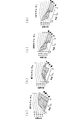
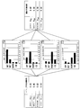
天候モデル記憶部35bは、4個の天候モデルMR(R;DRY,WET,SNOW,ICE)を記憶する。 図8(a)~(d)は、天候モデルMRの一例を示す図で、各軸は、それぞれ、気温(℃)、天候(1;晴れ、2;曇り、3;雨、4;雪)、気温がT℃で、天候がm(m=1~4)のときに路面状態がRとなる確率pTmRである。確率pTmRは、2変数(Tとm)の関数なので、曲面で現せる。
なお、確率pTmRの総和Σp=pTmD+pTmW+pTmS+pTmIは1にはならないので、実際に使用する場合には、規格化したものを用いる。以下、PTmR=pTmD/Σpを発生頻度という。
例えば、図9(a)に示すように、気温が8℃で、天候が晴れ(m=1)のときは、路面状態がDRYである発生頻度P8,1,Dは0.7、路面状態がWETである発生頻度P8,1,Wは0.2、路面状態がSNOWである発生頻度P8,1,Sと路面状態がICEである発生頻度P8,1,Iとは0.05となる。また、図9(b)に示すように、気温が-3℃で、天候が雪(m=4)のときは、路面状態がDRYである発生頻度P-3,4,Dと路面状態がWETである発生頻度P-3,4,Wとは0.05で、路面状態がSNOWである発生頻度P-3,4,Sは0.7、路面状態がICEである発生頻度P-3,4,Iは0.2となる。
天候モデルMRは、所定の場所Lrにおける過去の気象状態と路面状態のデータを用いて作成される。なお、季節毎あるいは月毎に天候モデルMRを作成してもよい。また、本例では、天候を4つ、気温を-10℃~10℃としているが、天候を更に細かく分類したり、気温の範囲や目盛りの間隔を変更してもよい。
前記実施の形態1においては、各車両が走行している場所の天候の変化を考慮していなかったが、図7に示すように、実施の形態1の図1に記載した路面状態予測装置30の、予測統計データ作成手段33と路面状態予測手段34との間に、天候補正手段35を設けて、路面状態予測手段34で予測された時刻tpでの路面状態R(tp)を、所定の範囲の場所Lrにおける時刻tpの気象予報データに基づいて補正すれば、路面状態の予測精度を更に向上させることができる。
天候補正手段35は、気象予報データ取得部35aと、天候モデル記憶部35bと、天候補正部35cとを備える。
気象予報データ取得部35aは、図外のインターネットに接続して、時刻tpを含む時間帯の天候と気温の予報データを取得する。
天候モデル記憶部35bは、4個の天候モデルMR(R;DRY,WET,SNOW,ICE)を記憶する。 図8(a)~(d)は、天候モデルMRの一例を示す図で、各軸は、それぞれ、気温(℃)、天候(1;晴れ、2;曇り、3;雨、4;雪)、気温がT℃で、天候がm(m=1~4)のときに路面状態がRとなる確率pTmRである。確率pTmRは、2変数(Tとm)の関数なので、曲面で現せる。
なお、確率pTmRの総和Σp=pTmD+pTmW+pTmS+pTmIは1にはならないので、実際に使用する場合には、規格化したものを用いる。以下、PTmR=pTmD/Σpを発生頻度という。
例えば、図9(a)に示すように、気温が8℃で、天候が晴れ(m=1)のときは、路面状態がDRYである発生頻度P8,1,Dは0.7、路面状態がWETである発生頻度P8,1,Wは0.2、路面状態がSNOWである発生頻度P8,1,Sと路面状態がICEである発生頻度P8,1,Iとは0.05となる。また、図9(b)に示すように、気温が-3℃で、天候が雪(m=4)のときは、路面状態がDRYである発生頻度P-3,4,Dと路面状態がWETである発生頻度P-3,4,Wとは0.05で、路面状態がSNOWである発生頻度P-3,4,Sは0.7、路面状態がICEである発生頻度P-3,4,Iは0.2となる。
天候モデルMRは、所定の場所Lrにおける過去の気象状態と路面状態のデータを用いて作成される。なお、季節毎あるいは月毎に天候モデルMRを作成してもよい。また、本例では、天候を4つ、気温を-10℃~10℃としているが、天候を更に細かく分類したり、気温の範囲や目盛りの間隔を変更してもよい。
天候補正部35cは、気象予報データ取得部35aで取得した時刻tpを含む時間帯の天候mと気温Tの予報データに基づいて、天候モデル記憶部35bに保存されている天候モデルから、天候がmで気温Tであるときの発生頻度PTmD,PTmW,PTmS,PTmIのデータを取り出し、これらの発生頻度PTmD,PTmW,PTmS,PTmIを用いて、予測統計データ作成手段33で算出された路面状態Rの予測出現割合SRpを補正する。
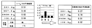
具体的には、図10に示すように、前記実施の形態1で予測した時刻tpにおける路面状態Rの予測出現割合SRpに天候モデルの発生頻度PTmRを積算した値を補正後の路面状態Rの予測出現割合SRpzとし、各路面状態のSRpzを比較することで、時刻tpにおける路面状態Rを予測する。ここでは、天候を雨(m=3)、気温をT=1℃としたので、DRY路面の発生頻度はPTmD=0.17であり、WET路面の発生頻度はPTmW=0.51、SNOW路面の発生頻度はPTmS=0.16、ICE路面の発生頻度はPTmI=0.16である。
補正後のDRY路面の予測出現割合はSDpz=PTmD・SDpにより算出され、WET路面の予測出現割合はSWpz=PTmW・SWpにより算出される。また、SNOW路面の予測出現割合SSpz=PTmS・SSpにより算出され、ICE路面の予測出現割合はSIpz=PTmI・SIpSによりそれぞれ算出される。
なお、図10では、補正後の路面状態Rの予測出現割合SRpzの値を、総和(ΣRSRpz)が1になるように規格化したものを記載している。
路面状態予測手段34では、補正された予測値(予測出現割合SRpz)が最も大きな路面状態を所定の範囲内の場所Lkの、時刻tpにおける路面状態Rz(tp)であると予測する。
このような路面状態の予測結果を使って、路面状態の予測を繰り返せば、更に将来の時刻tq(tq>tp)での、天候を考慮した路面状態Rz(tq)を予測することができる。
具体的には、図10に示すように、前記実施の形態1で予測した時刻tpにおける路面状態Rの予測出現割合SRpに天候モデルの発生頻度PTmRを積算した値を補正後の路面状態Rの予測出現割合SRpzとし、各路面状態のSRpzを比較することで、時刻tpにおける路面状態Rを予測する。ここでは、天候を雨(m=3)、気温をT=1℃としたので、DRY路面の発生頻度はPTmD=0.17であり、WET路面の発生頻度はPTmW=0.51、SNOW路面の発生頻度はPTmS=0.16、ICE路面の発生頻度はPTmI=0.16である。
補正後のDRY路面の予測出現割合はSDpz=PTmD・SDpにより算出され、WET路面の予測出現割合はSWpz=PTmW・SWpにより算出される。また、SNOW路面の予測出現割合SSpz=PTmS・SSpにより算出され、ICE路面の予測出現割合はSIpz=PTmI・SIpSによりそれぞれ算出される。
なお、図10では、補正後の路面状態Rの予測出現割合SRpzの値を、総和(ΣRSRpz)が1になるように規格化したものを記載している。
路面状態予測手段34では、補正された予測値(予測出現割合SRpz)が最も大きな路面状態を所定の範囲内の場所Lkの、時刻tpにおける路面状態Rz(tp)であると予測する。
このような路面状態の予測結果を使って、路面状態の予測を繰り返せば、更に将来の時刻tq(tq>tp)での、天候を考慮した路面状態Rz(tq)を予測することができる。
実施の形態3.
前記実施の形態2では、天候がmで気温Tであるときの発生頻度PTmD,PTmW,PTmS,PTmIを用いて、路面状態Rの予測出現割合SRpを補正することで、天候を考慮した路面状態Rz(tp)を予測するようにしたが、図11に示すように、実施の形態2の図7に記載した路面状態予測装置30の、予測統計データ作成手段33と天候補正手段35との間に、路面状態毎の基準マップMR0(R;DRY路面,WET路面,SNOW路面,ICE路面)を保存するマップ記憶手段36と、路面状態毎の基準マップMR0を用いて、予測統計データ作成手段33で作成された路面状態Rの予測出現割合SRpの適合度Jを算出する適合度算出手段37とを設けるとともに、天候補正部35cに代えて、算出された適合度Jと天候がmで気温Tであるときの発生頻度PTmD,PTmW,PTmS,PTmIとから路面状態RZ(tp)を予測する天候確率付加部35dを設けて、天候を考慮した路面状態RZ(tp)を予測するようにすれば、路面状態の予測精度を更に向上させることができる。
なお、適合度J及び路面状態毎の基準マップMR0については、後述する。
前記実施の形態2では、天候がmで気温Tであるときの発生頻度PTmD,PTmW,PTmS,PTmIを用いて、路面状態Rの予測出現割合SRpを補正することで、天候を考慮した路面状態Rz(tp)を予測するようにしたが、図11に示すように、実施の形態2の図7に記載した路面状態予測装置30の、予測統計データ作成手段33と天候補正手段35との間に、路面状態毎の基準マップMR0(R;DRY路面,WET路面,SNOW路面,ICE路面)を保存するマップ記憶手段36と、路面状態毎の基準マップMR0を用いて、予測統計データ作成手段33で作成された路面状態Rの予測出現割合SRpの適合度Jを算出する適合度算出手段37とを設けるとともに、天候補正部35cに代えて、算出された適合度Jと天候がmで気温Tであるときの発生頻度PTmD,PTmW,PTmS,PTmIとから路面状態RZ(tp)を予測する天候確率付加部35dを設けて、天候を考慮した路面状態RZ(tp)を予測するようにすれば、路面状態の予測精度を更に向上させることができる。
なお、適合度J及び路面状態毎の基準マップMR0については、後述する。
図12に示すように、DRY路面の基準マップMD0は、標準タイヤを装着した試験車両をDRY路面にて一定速度で多数回走行させて得られた推定路面状態の統計データで、DRY路面を走行したときに、路面がDRY路面であると推定した割合PDD0と、路面がWET路面であると推定される割合PDW0と、路面がSNOW路面であると推定される割合PDS0と、路面がICE路面であると推定される割合PDI0とをマップ化したものである。
また、WET路面の基準マップMW0は、試験車両がWET路面を走行したときに、路面がDRY路面であると推定した割合PWD0と、路面がWET路面であると推定される割合PWW0と、路面がSNOW路面であると推定される割合PWS0と、路面がICE路面であると推定される割合PWI0とをマップ化したもので、SNOW路面の基準マップMS0は、試験車両がSNOW路面を走行したときに、路面がDRY路面であると推定した割合PSD0、路面がWET路面であると推定される割合PSW0、路面がSNOW路面であると推定される割合PSS0、路面がICE路面であると推定される割合PSI0をマップ化したものである。
また、ICE路面の基準マップMI0は、試験車両がICE路面を走行したときに、路面がDRY路面であると推定した割合PID0、路面がWET路面であると推定される割合PIW0、路面がSNOW路面であると推定される割合PIS0、路面がICE路面であると推定される割合PII0をマップ化したものである。
当然のことながら、基準マップMD0ではPDD0が最も高く、基準マップMW0ではPWW0が最も高く、基準マップMS0ではPSS0が最も高く、基準マップMI0ではPII0が最も高い。
以下、前記の割合PRR’0を基準出現割合という。ここで、R,R’は、D,W,S,Iのうちのいずれかを指す。
また、WET路面の基準マップMW0は、試験車両がWET路面を走行したときに、路面がDRY路面であると推定した割合PWD0と、路面がWET路面であると推定される割合PWW0と、路面がSNOW路面であると推定される割合PWS0と、路面がICE路面であると推定される割合PWI0とをマップ化したもので、SNOW路面の基準マップMS0は、試験車両がSNOW路面を走行したときに、路面がDRY路面であると推定した割合PSD0、路面がWET路面であると推定される割合PSW0、路面がSNOW路面であると推定される割合PSS0、路面がICE路面であると推定される割合PSI0をマップ化したものである。
また、ICE路面の基準マップMI0は、試験車両がICE路面を走行したときに、路面がDRY路面であると推定した割合PID0、路面がWET路面であると推定される割合PIW0、路面がSNOW路面であると推定される割合PIS0、路面がICE路面であると推定される割合PII0をマップ化したものである。
当然のことながら、基準マップMD0ではPDD0が最も高く、基準マップMW0ではPWW0が最も高く、基準マップMS0ではPSS0が最も高く、基準マップMI0ではPII0が最も高い。
以下、前記の割合PRR’0を基準出現割合という。ここで、R,R’は、D,W,S,Iのうちのいずれかを指す。
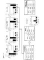
適合度算出手段37では、図12に示すように、路面毎の基準マップMD0~MI0を用いて、予測統計データ作成手段33で作成された予測統計データMpCである予測出現割合SRpの適合度JR(R;DRY,WET,SNOW,ICE)をそれぞれ算出し、これら算出された4つの適合度JRを天候補正手段35の天候確率付加部35dに送る。
DRY適合度JDは、予測統計データMpCにおける予測出現割合SRpと、上述した、基準マップMD0における基準出現割合PDD0,PDW0,PDS0,PDI0とを用いて、以下の式(1)により算出される。
JD=exp{-(|SDp-PDD0|2+|SWp-PDW0|2
+|SSp-PDS0|2+|SIp-PDI0|2 )} ……(1)
同様に、WET適合度JW、SNOW適合度JS、ICE適合度JIは、それぞれ、以下の式(2)~(4)により算出される。
JW=exp{-(|SDp-PWD0|2+|SWp-PWW0|2
+|SSp-PWS0|2+|SIp-PWI0|2 )} ……(2)
JS=exp{-(|SDp-PSD0|2+|SWp-PSW0|2
+|SSp-PSS0|2+|SIp-PSI0|2 )} ……(3)
JI=exp{-(|SDp-PID0|2+|SWp-PIW0|2
+|SSp-PIS0|2+|SIp-PII0|2)} ……(4)
天候確率付加部35dでは、天候がmで気温Tであるときの発生頻度PTmRと、適合度算出手段37で算出された適合度JRとの積を用いて、天候がmで気温Tであるときの路面状態の出現割合SRpZを算出する。
天候がmで気温TであるときのDRY路面の予測出現割合はSDpZ=PTmD・JDにより算出され、WET路面の予測出現割合はSWpZ=PTmW・JWにより算出される。また、SNOW路面の予測出現割合SSpZ=PTmS・JSにより算出され、ICE路面の予測出現割合はSIpZ=PTmI・JIによりそれぞれ算出される。
なお、図12では、天候がmで気温Tであるときの路面状態Rの予測出現割合SRpZの値を、総和(ΣRSRpZ)が1になるように規格化したものを記載している。
路面状態予測手段34では、天候がmで気温Tであるときの予測値(予測出現割合SRpZ)が最も大きな路面状態を所定の範囲内の場所Lkの、時刻tpにおける路面状態RZ(tp)であると予測する。
このような路面状態の予測結果を使って、路面状態の予測を繰り返せば、更に将来の時刻tq(tq>tp)での、天候を考慮した路面状態RZ(tq)を予測することができる。
DRY適合度JDは、予測統計データMpCにおける予測出現割合SRpと、上述した、基準マップMD0における基準出現割合PDD0,PDW0,PDS0,PDI0とを用いて、以下の式(1)により算出される。
JD=exp{-(|SDp-PDD0|2+|SWp-PDW0|2
+|SSp-PDS0|2+|SIp-PDI0|2 )} ……(1)
同様に、WET適合度JW、SNOW適合度JS、ICE適合度JIは、それぞれ、以下の式(2)~(4)により算出される。
JW=exp{-(|SDp-PWD0|2+|SWp-PWW0|2
+|SSp-PWS0|2+|SIp-PWI0|2 )} ……(2)
JS=exp{-(|SDp-PSD0|2+|SWp-PSW0|2
+|SSp-PSS0|2+|SIp-PSI0|2 )} ……(3)
JI=exp{-(|SDp-PID0|2+|SWp-PIW0|2
+|SSp-PIS0|2+|SIp-PII0|2)} ……(4)
天候確率付加部35dでは、天候がmで気温Tであるときの発生頻度PTmRと、適合度算出手段37で算出された適合度JRとの積を用いて、天候がmで気温Tであるときの路面状態の出現割合SRpZを算出する。
天候がmで気温TであるときのDRY路面の予測出現割合はSDpZ=PTmD・JDにより算出され、WET路面の予測出現割合はSWpZ=PTmW・JWにより算出される。また、SNOW路面の予測出現割合SSpZ=PTmS・JSにより算出され、ICE路面の予測出現割合はSIpZ=PTmI・JIによりそれぞれ算出される。
なお、図12では、天候がmで気温Tであるときの路面状態Rの予測出現割合SRpZの値を、総和(ΣRSRpZ)が1になるように規格化したものを記載している。
路面状態予測手段34では、天候がmで気温Tであるときの予測値(予測出現割合SRpZ)が最も大きな路面状態を所定の範囲内の場所Lkの、時刻tpにおける路面状態RZ(tp)であると予測する。
このような路面状態の予測結果を使って、路面状態の予測を繰り返せば、更に将来の時刻tq(tq>tp)での、天候を考慮した路面状態RZ(tq)を予測することができる。
前記実施の形態3では、予測統計データMpCにおける予測出現割合SRpと路面状態毎の基準マップMR0とから求めた適合度JRに天候モデルの発生頻度PTmRを積算して、天候がmで気温Tであるときの路面状態Rの予測出現割合SDpZを予測したが、各天候m(m=1~4)及び温度Tにおける各路面状態Rの出現割合PRmTをマップ化した路面天候モデルMRmTを作成し、データ作成手段33で作成された路面状態Rの予測出現割合SRpと路面天候モデルMRmTとから予測出現割合を予測してもよい。
また、前記実施の形態1~3では、複数台の車両Wiで推定された、推定路面状態の出現割合SRkを路面状態R毎に算出した実統計データMk用いて、時刻tpにおける路面状態R(tp)を予測したが、時刻tkにおいて所定の場所Lrを通過した車両が、車両Wx1台だった場合には、時刻tkにおける実統計データMkは作成できない。
そこで、この場合には、前記実施の形態3に記載した路面状態毎の基準マップMR0を実統計データMkとする。
具体的には、車両Wxで推定した推定路面状態がDRY路面であった場合には、DRY路面の基準マップMD0を、時刻tkにおける実統計データMkとする。
基準マップMD0は、上述したように、DRY路面を走行したときに、路面がDRY路面であると推定した割合PDD0と、路面がWET路面であると推定される割合PDW0と、路面がSNOW路面であると推定される割合PDS0と、路面がICE路面であると推定される割合PDI0とをマップ化したものなので、基準マップMD0を実統計データMkの代用して用いれば、DRY路面の出現割合を1.0とした場合に比較して、実際に近い実統計データMkとなるので、路面状態の予測精度を十分に確保することができる。
また、所定の場所Lrを通過した車両が少数台(例えば、10台未満)である場合にも適用できる。例えば、通過車両が3台で、車両Wxと車両Wyとで推定した推定路面状態がDRY路面で、車両Wzで推定した推定路面状態がWET路面であった場合には、基準マップMD0と基準マップMW0とから実統計データMkを作成すればよい。このとき、基準マップMD0に対する重みを2(重み係数wD=2/3)、基準マップMW0に対する重みを1(重み係数wW=1/3)とするなど、台数による重み付けを行うことが好ましい。
このように、予め路面状態毎の基準マップMR0を作成しておけば、所定の場所Lrを通過した車両が少数台であったとしても、将来の路面状態を精度よく予測することができる。
そこで、この場合には、前記実施の形態3に記載した路面状態毎の基準マップMR0を実統計データMkとする。
具体的には、車両Wxで推定した推定路面状態がDRY路面であった場合には、DRY路面の基準マップMD0を、時刻tkにおける実統計データMkとする。
基準マップMD0は、上述したように、DRY路面を走行したときに、路面がDRY路面であると推定した割合PDD0と、路面がWET路面であると推定される割合PDW0と、路面がSNOW路面であると推定される割合PDS0と、路面がICE路面であると推定される割合PDI0とをマップ化したものなので、基準マップMD0を実統計データMkの代用して用いれば、DRY路面の出現割合を1.0とした場合に比較して、実際に近い実統計データMkとなるので、路面状態の予測精度を十分に確保することができる。
また、所定の場所Lrを通過した車両が少数台(例えば、10台未満)である場合にも適用できる。例えば、通過車両が3台で、車両Wxと車両Wyとで推定した推定路面状態がDRY路面で、車両Wzで推定した推定路面状態がWET路面であった場合には、基準マップMD0と基準マップMW0とから実統計データMkを作成すればよい。このとき、基準マップMD0に対する重みを2(重み係数wD=2/3)、基準マップMW0に対する重みを1(重み係数wW=1/3)とするなど、台数による重み付けを行うことが好ましい。
このように、予め路面状態毎の基準マップMR0を作成しておけば、所定の場所Lrを通過した車両が少数台であったとしても、将来の路面状態を精度よく予測することができる。
また、前記実施の形態1~3では、路面状態の予測に複数台の車両Wiを用いたが、前記の路面状態毎の基準マップMR0を用いれば、1台の車両Wpを、複数の所定の場所Lrを含む経路を複数回走行させることで、複数の所定の場所Lrにおける路面状態Rr(tp)を予測することも可能である。
すなわち、時刻ta,tb,tc,……には、所定の場所Lrにおける推定路面状態が、時刻ta+h,tb+h,tc+h,……には、所定の場所Lr’における推定路面状態が、車両Wpからサーバー20に送られてくる。例えば、所定の場所Lrでは、時刻ta,tb,tc,……(a<b<c<0)と経過するにしたがって、推定路面状態Rが変化する。そこで、時刻tm(m>0)において車両Wpが推定した推定路面状態Rを、路面Rの基準マップMR0に置き換えて、これを実統計データMkとすれば、前記実施の形態1~3と同様に、時刻tmでの路面状態を予測することができる。なお、基準マップMR0は、車両Wp毎に変更してもよい。
すなわち、時刻ta,tb,tc,……には、所定の場所Lrにおける推定路面状態が、時刻ta+h,tb+h,tc+h,……には、所定の場所Lr’における推定路面状態が、車両Wpからサーバー20に送られてくる。例えば、所定の場所Lrでは、時刻ta,tb,tc,……(a<b<c<0)と経過するにしたがって、推定路面状態Rが変化する。そこで、時刻tm(m>0)において車両Wpが推定した推定路面状態Rを、路面Rの基準マップMR0に置き換えて、これを実統計データMkとすれば、前記実施の形態1~3と同様に、時刻tmでの路面状態を予測することができる。なお、基準マップMR0は、車両Wp毎に変更してもよい。
実施の形態4.
前記実施の形態1では、所定の範囲内の場所において推定した、複数の時刻tk(k=-n~-1)での路面状態Rの時間変化から、将来の時刻tp(p>0)での路面状態R(tp)の予測出現割合SRpを予測したが、図13に示すように、路面状態遷移予測手段38を設けて、統計データ作成手段31で作成した過去のデータのうち、時刻t-1のデータから、将来の時刻tpにおける路面状態R(tp)の予測出現割合SRpを予測してもよい。
なお、本例では、統計データ作成手段31は、サーバー20のデータ記憶手段22の保存されたデータから、所定の範囲内の場所がLrで、時刻tが予測する時刻tpの直前の時刻t(r)-1において推定した推定路面状態Rの出現割合を、推定路面状態R(R;DRY路面,WET路面,SNOW路面,ICE路面)毎に集計したマップを作成する。
路面状態遷移予測手段38は、遷移モデル記憶部38aと、出現割合予測値算出部38bとを備える。
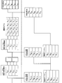
遷移モデル記憶部38aは、図14に示すように、4個の遷移モデルTR(R;DRY,WET,SNOW,ICE)を記憶する。
遷移モデルTRは、時刻tkにおいて路面状態がRkであったものが、時刻tk+1において路面状態R’になる確率(以下、遷移確率という)qR,R’を表すもので、路面状態R毎に作成される。
例えば、同図の中央上段に示すDRY遷移モデルTDでは、DRY路面の状態が継続する確率qD,Dは0.7、DRY路面であったものがWET路面となる遷移確率qD,Wは0.2、DRY路面であったものがSNOW路面となる遷移確率qD,Sは0.05、DRY路面であったものがICE路面となる遷移確率qD,Iは0.05となっている。これらの遷移確率qR,Rは、過去の路面状態Rのデータを用いて作成される。
出現割合予測値算出部38bでは、時刻t-1における推定路面状態がRである出現割合SR-1を上記の遷移確率qR,R’を用いて補正して、出現割合予測値SRptを算出する。出現割合予測値SRptは、路面状態R毎に算出する。
各路面状態Rの出現割合予測値SDpt,SWpt,SSpt,SIptは、それぞれ、以下の式(5)~(8)により算出される。
SDpt=SD-1・qD,D+SW-1・qW,D+SS-1・qS,D+SI-1・qI,D ……(5)
SWpt=SD-1・qD,W+SW-1・qW,W+SS-1・qS,W+SI-1・qI,W ……(6)
SSpt=SD-1・qD,S+SW-1・qW,S+SS-1・qS,S+SI-1・qI,S ……(7)
SIpt=SD-1・qD,I+SW-1・qW,I+SS-1・qS,I+SI-1・qI,I ……(8)
路面状態予測手段34では、これらの出現割合予測値SDpt,SWpt,SSpt,SIptが最も大きい路面状態を、所定の範囲内の場所Lkの、時刻tpにおける路面状態R(tp)であると予測する。
このように、予め求めておいた路面状態の遷移確率qR,R’と、過去のデータとしての時刻t-1における推定路面状態Rの出現割合SR-1とから、将来の時刻tp(p>0)における路面状態Rの予測出現割合SRptを予測したので、簡単な構成で将来の時刻tpでの路面状態Rt(tp)を予測することができる。
前記実施の形態1では、所定の範囲内の場所において推定した、複数の時刻tk(k=-n~-1)での路面状態Rの時間変化から、将来の時刻tp(p>0)での路面状態R(tp)の予測出現割合SRpを予測したが、図13に示すように、路面状態遷移予測手段38を設けて、統計データ作成手段31で作成した過去のデータのうち、時刻t-1のデータから、将来の時刻tpにおける路面状態R(tp)の予測出現割合SRpを予測してもよい。
なお、本例では、統計データ作成手段31は、サーバー20のデータ記憶手段22の保存されたデータから、所定の範囲内の場所がLrで、時刻tが予測する時刻tpの直前の時刻t(r)-1において推定した推定路面状態Rの出現割合を、推定路面状態R(R;DRY路面,WET路面,SNOW路面,ICE路面)毎に集計したマップを作成する。
路面状態遷移予測手段38は、遷移モデル記憶部38aと、出現割合予測値算出部38bとを備える。
遷移モデル記憶部38aは、図14に示すように、4個の遷移モデルTR(R;DRY,WET,SNOW,ICE)を記憶する。
遷移モデルTRは、時刻tkにおいて路面状態がRkであったものが、時刻tk+1において路面状態R’になる確率(以下、遷移確率という)qR,R’を表すもので、路面状態R毎に作成される。
例えば、同図の中央上段に示すDRY遷移モデルTDでは、DRY路面の状態が継続する確率qD,Dは0.7、DRY路面であったものがWET路面となる遷移確率qD,Wは0.2、DRY路面であったものがSNOW路面となる遷移確率qD,Sは0.05、DRY路面であったものがICE路面となる遷移確率qD,Iは0.05となっている。これらの遷移確率qR,Rは、過去の路面状態Rのデータを用いて作成される。
出現割合予測値算出部38bでは、時刻t-1における推定路面状態がRである出現割合SR-1を上記の遷移確率qR,R’を用いて補正して、出現割合予測値SRptを算出する。出現割合予測値SRptは、路面状態R毎に算出する。
各路面状態Rの出現割合予測値SDpt,SWpt,SSpt,SIptは、それぞれ、以下の式(5)~(8)により算出される。
SDpt=SD-1・qD,D+SW-1・qW,D+SS-1・qS,D+SI-1・qI,D ……(5)
SWpt=SD-1・qD,W+SW-1・qW,W+SS-1・qS,W+SI-1・qI,W ……(6)
SSpt=SD-1・qD,S+SW-1・qW,S+SS-1・qS,S+SI-1・qI,S ……(7)
SIpt=SD-1・qD,I+SW-1・qW,I+SS-1・qS,I+SI-1・qI,I ……(8)
路面状態予測手段34では、これらの出現割合予測値SDpt,SWpt,SSpt,SIptが最も大きい路面状態を、所定の範囲内の場所Lkの、時刻tpにおける路面状態R(tp)であると予測する。
このように、予め求めておいた路面状態の遷移確率qR,R’と、過去のデータとしての時刻t-1における推定路面状態Rの出現割合SR-1とから、将来の時刻tp(p>0)における路面状態Rの予測出現割合SRptを予測したので、簡単な構成で将来の時刻tpでの路面状態Rt(tp)を予測することができる。
なお、前記実施の形態4では、過去のデータから予め求めておいた遷移確率qR,R’を用いて出現割合予測値SDpt,SWpt,SSpt,SIptを求めたが、遷移確率として、同じ路面状態Rが維持される確率を、例えば、q’R,R=0.8とし、路面状態Rが路面状態R’に遷移する確率を、それぞれ、q’R,R’=(0.2)/3としてもよい。なお、分母3は、路面状態R以外の路面状態R’の数である。
この場合の各路面状態Rの出現割合予測値S’Dpt,S’Wpt,S’Spt,S’Iptは、それぞれ、以下の式(5’)~(8’)により算出される。
S’Dpt=SD-1・0.8+SW-1・0.2/3+SS-1・0.2/3+SI-1・0.2/3 ……(5’)
S’Wpt=SD-1・0.2/3+SW-1・0.8+SS-1・0.2/3+SI-1・0.2/3 ……(6’)
S’Spt=SD-1・0.2/3+SW-1・0.2/3+SS-1・0.8+SI-1・0.2/3 ……(7’)
S’Ipt=SD-1・0.2/3+SW-1・0.2/3+SS-1・0.2/3+SI-1・0.8 ……(8’)
このように、予め設定された推定路面状態の遷移確率q’RR’、もしくは、予め求めておいた推定路面状態の遷移確率qRR’を用いて、時刻tpにおける路面状態を予測する方法を、過去データ数が少ない初期段階での予測に用いれば、十分な過去データ数がない状況でも、予測を行うことが可能である。
この場合の各路面状態Rの出現割合予測値S’Dpt,S’Wpt,S’Spt,S’Iptは、それぞれ、以下の式(5’)~(8’)により算出される。
S’Dpt=SD-1・0.8+SW-1・0.2/3+SS-1・0.2/3+SI-1・0.2/3 ……(5’)
S’Wpt=SD-1・0.2/3+SW-1・0.8+SS-1・0.2/3+SI-1・0.2/3 ……(6’)
S’Spt=SD-1・0.2/3+SW-1・0.2/3+SS-1・0.8+SI-1・0.2/3 ……(7’)
S’Ipt=SD-1・0.2/3+SW-1・0.2/3+SS-1・0.2/3+SI-1・0.8 ……(8’)
このように、予め設定された推定路面状態の遷移確率q’RR’、もしくは、予め求めておいた推定路面状態の遷移確率qRR’を用いて、時刻tpにおける路面状態を予測する方法を、過去データ数が少ない初期段階での予測に用いれば、十分な過去データ数がない状況でも、予測を行うことが可能である。
実施の形態5.
前記実施の形態4では、過去のデータ(t=t-1)と、予め求めておいた路面状態の遷移確率とから求めた出現割合予測値SRptとを用いて、将来の時刻tpにおける路面状態R(tp)を予測したが、時刻t-1における予測出現割合である直前予測出現割合VR-1と、実施の形態4に記載の遷移確率qR,R’と、実施の形態1で求めた予測出現割合SRpと用いて将来の時刻tpにおける路面状態Rの予測出現割合VRpを求め、これらの出現割合予測値VDp,VWp,VSp,VIpを用いて、時刻tpにおける路面状態R(tp)を予測すれば、将来の路面状態を更に精度よく予測することができる。
予測出現割合VRpを求める手順について、図15を参照して説明する。
予測出現割合VRpの算出は、時刻t-1まで直前予測出現割合VR-n,……,VR-2,VR-1(計算値)と、実統計データM-n,……,M-2,M-1とが得られている状態で行う。なお、最初の直前予測出現割合VR-nは設定値である。
まず、時刻t-1における直前予測出現割合VR-1と遷移確率qR,R’との積PR,R’pを求める(手順1)。
次に、時刻tpよりも前の時刻t-n,……,t-3,t-2,t-1における実統計データM-n,……,M-3,M-2,M-1から、時刻tpにおける予測出現割合SRpを求める(手順2)。なお、予測出現割合SRkの予測方法については、実施の形態1と同様であるので、説明を省略する。
そして、手順1で求めた積PR,R’pと手順2で求めた予測出現割合SRpとの積VRpを算出し、この積VRpを将来の時刻tpにおける路面状態Rの予測出現割合とする(手順3)。
最後に、これらの予測出現割合VDp,VWp,VSp,VIpの大きさを比較し、最も大きい路面状態を、所定の範囲内の場所Lkの、時刻tpにおける路面状態R(tp)であると予測する(手順4)。なお、手順2を先にし手順1を後にしてもよい。
ところで、時刻tpにおける実統計データMpが実測された場合には、当然のことながら、時刻tpは「直前の時刻t-1」となり、時刻t-1が時刻t-2となり、最初の時刻t-nが時刻t-n-1となる(過去の時刻が1つ増える)。
図15では、時刻t-kにおける予測出現割合をSRp=-kとし、時刻t-kにおける実測値である出現割合SR-kと区別している。予測出現割合SRp=-kは、時刻tkにおける実統計データMkが実測された時点で、出現割合SR-kに置き換えられる。
このような操作を繰り返すことにより、更に将来の時刻tq(tq>tp)での路面状態R(tq)を予測することができる。
前記実施の形態4では、過去のデータ(t=t-1)と、予め求めておいた路面状態の遷移確率とから求めた出現割合予測値SRptとを用いて、将来の時刻tpにおける路面状態R(tp)を予測したが、時刻t-1における予測出現割合である直前予測出現割合VR-1と、実施の形態4に記載の遷移確率qR,R’と、実施の形態1で求めた予測出現割合SRpと用いて将来の時刻tpにおける路面状態Rの予測出現割合VRpを求め、これらの出現割合予測値VDp,VWp,VSp,VIpを用いて、時刻tpにおける路面状態R(tp)を予測すれば、将来の路面状態を更に精度よく予測することができる。
予測出現割合VRpを求める手順について、図15を参照して説明する。
予測出現割合VRpの算出は、時刻t-1まで直前予測出現割合VR-n,……,VR-2,VR-1(計算値)と、実統計データM-n,……,M-2,M-1とが得られている状態で行う。なお、最初の直前予測出現割合VR-nは設定値である。
まず、時刻t-1における直前予測出現割合VR-1と遷移確率qR,R’との積PR,R’pを求める(手順1)。
次に、時刻tpよりも前の時刻t-n,……,t-3,t-2,t-1における実統計データM-n,……,M-3,M-2,M-1から、時刻tpにおける予測出現割合SRpを求める(手順2)。なお、予測出現割合SRkの予測方法については、実施の形態1と同様であるので、説明を省略する。
そして、手順1で求めた積PR,R’pと手順2で求めた予測出現割合SRpとの積VRpを算出し、この積VRpを将来の時刻tpにおける路面状態Rの予測出現割合とする(手順3)。
最後に、これらの予測出現割合VDp,VWp,VSp,VIpの大きさを比較し、最も大きい路面状態を、所定の範囲内の場所Lkの、時刻tpにおける路面状態R(tp)であると予測する(手順4)。なお、手順2を先にし手順1を後にしてもよい。
ところで、時刻tpにおける実統計データMpが実測された場合には、当然のことながら、時刻tpは「直前の時刻t-1」となり、時刻t-1が時刻t-2となり、最初の時刻t-nが時刻t-n-1となる(過去の時刻が1つ増える)。
図15では、時刻t-kにおける予測出現割合をSRp=-kとし、時刻t-kにおける実測値である出現割合SR-kと区別している。予測出現割合SRp=-kは、時刻tkにおける実統計データMkが実測された時点で、出現割合SR-kに置き換えられる。
このような操作を繰り返すことにより、更に将来の時刻tq(tq>tp)での路面状態R(tq)を予測することができる。
なお、前記実施の形態5では、積PR,R’pと予測出現割合SRpとの積を将来の時刻tpにおける路面状態Rの予測出現割合VRpとしたが、予測出現割合SRpに代えて、各路面状態に対応するモデルである基準マップMR0における基準出現割合PRR’と予測出現割合SRpとの適合度JRpを用いてもよい。適合度JRpは、実施の形態3の場合と同様に、以下の式(9)により算出される。
JRp=exp{-(|SDp-PRD0|2+|SWp-PRW0|2
+|SSp-PRS0|2+|SIp-PRI0|2 )}……(9)
また、前記実施の形態5では、予測出現割合として、実施の形態1で求めた予測出現割合SRpを用いたが、実施の形態2で求めた天候モデルにより補正した予測出現割合SRpz、もしくは、実施の形態3で求めた、路面状態毎の基準マップMR0と天候モデルとを用いて補正した予測出現割合SRpZを用いて路面状態Rの予測出現割合VRpを求めれば、天候の変化を考慮した予測を行うことができるので、将来の路面状態を更に精度よく予測することができる。
なお、天候の変化を考慮した予測を行う方法としては、気象予報データである天候、もしくは、天候と気温毎に遷移モデルTRTを作成し、この遷移モデルTRTと、直前予測出現割合VR-1と、予測出現割合SRpとを用いて、将来の時刻tpにおける路面状態Rの予測出現割合VRpを求めるようにしてもよい。
JRp=exp{-(|SDp-PRD0|2+|SWp-PRW0|2
+|SSp-PRS0|2+|SIp-PRI0|2 )}……(9)
また、前記実施の形態5では、予測出現割合として、実施の形態1で求めた予測出現割合SRpを用いたが、実施の形態2で求めた天候モデルにより補正した予測出現割合SRpz、もしくは、実施の形態3で求めた、路面状態毎の基準マップMR0と天候モデルとを用いて補正した予測出現割合SRpZを用いて路面状態Rの予測出現割合VRpを求めれば、天候の変化を考慮した予測を行うことができるので、将来の路面状態を更に精度よく予測することができる。
なお、天候の変化を考慮した予測を行う方法としては、気象予報データである天候、もしくは、天候と気温毎に遷移モデルTRTを作成し、この遷移モデルTRTと、直前予測出現割合VR-1と、予測出現割合SRpとを用いて、将来の時刻tpにおける路面状態Rの予測出現割合VRpを求めるようにしてもよい。
前記実施の形態4では、予め求めておいた遷移モデルTRと時刻t-1における出現割合SR-1とから、将来の時刻tpにおける路面状態R(tp)の予測出現割合SRptを予測したが、遷移モデルTRを、実統計データMkの遷移状態に応じて変更すれば、路面状態R(tp)の予測精度を更に向上させることができる。
以下、遷移モデルTRの変更方法について説明する。
まず、実測データである時刻t-1における出現割合SR-1が、時刻t-1の直前の時刻である時刻t-2における出現割合SR-2とからどのように変化したか調べる。
例えば、図16に示すように、時刻がt-2からt-1になったときに、DRY路面の出現割合がSD-2=0.7からSD-1=0.6に減少し、WET路面の出現割合がSW-2=0.1からSW-1=0.2に増加したとする(SNOWとICEについては変化なし)。
ここで、実測データにおける路面状態Rの出現割合の変化率を、vR-k=SR-k/SR-k-1とすると、vD-1=0.86、vW-1=2.0、vS-1=vI-1=1.00である。
そこで、遷移モデルTDにおけるDRY路面の状態が継続する確率を、qD,D=0.7から、uD,D=vD-1・qD,D=0.6に変更し、DRY路面であったものがWET路面となる遷移確率を、qD,W=0.2からuD,W=vW-1・qD,W=0.4に変更した後、変更後の遷移確率の総和が1となるように、uD,Rを規格化する。
上記の操作を、他の遷移モデルTW,TS,TIについても行うことで、遷移モデルTRを変更する。
以下、変更後の遷移モデルをURとし、路面状態がRからR’に遷移する確率をuR,R’とする。
次に、時刻t-1における推定路面状態がRである出現割合SR-1を、上記の遷移確率uR,R’を用いて補正して、出現割合予測値SRpTを算出する。
出現割合予測値SRpTの算出式を以下の式(10)に示す。
SRpT=SD-1・uD,R+SW-1・uW,R+SS-1・uS,R+SI-1・uI,R ……(10)
出現割合予測値SRpTは、路面状態R毎に算出する。
路面状態予測手段34では、これらの出現割合予測値SDpT,SWpT,SSpT,SIpTが最も大きい路面状態を、所定の範囲内の場所Lkの、時刻tpにおける路面状態RT(tp)であると予測する。
このように、路面状態の遷移確率qR,R’を、過去のデータ(実統計データMk)の遷移状態に応じて変更したので、将来の時刻tpでの路面状態Rt(tp)の予測精度を更に向上させることができる。
以下、遷移モデルTRの変更方法について説明する。
まず、実測データである時刻t-1における出現割合SR-1が、時刻t-1の直前の時刻である時刻t-2における出現割合SR-2とからどのように変化したか調べる。
例えば、図16に示すように、時刻がt-2からt-1になったときに、DRY路面の出現割合がSD-2=0.7からSD-1=0.6に減少し、WET路面の出現割合がSW-2=0.1からSW-1=0.2に増加したとする(SNOWとICEについては変化なし)。
ここで、実測データにおける路面状態Rの出現割合の変化率を、vR-k=SR-k/SR-k-1とすると、vD-1=0.86、vW-1=2.0、vS-1=vI-1=1.00である。
そこで、遷移モデルTDにおけるDRY路面の状態が継続する確率を、qD,D=0.7から、uD,D=vD-1・qD,D=0.6に変更し、DRY路面であったものがWET路面となる遷移確率を、qD,W=0.2からuD,W=vW-1・qD,W=0.4に変更した後、変更後の遷移確率の総和が1となるように、uD,Rを規格化する。
上記の操作を、他の遷移モデルTW,TS,TIについても行うことで、遷移モデルTRを変更する。
以下、変更後の遷移モデルをURとし、路面状態がRからR’に遷移する確率をuR,R’とする。
次に、時刻t-1における推定路面状態がRである出現割合SR-1を、上記の遷移確率uR,R’を用いて補正して、出現割合予測値SRpTを算出する。
出現割合予測値SRpTの算出式を以下の式(10)に示す。
SRpT=SD-1・uD,R+SW-1・uW,R+SS-1・uS,R+SI-1・uI,R ……(10)
出現割合予測値SRpTは、路面状態R毎に算出する。
路面状態予測手段34では、これらの出現割合予測値SDpT,SWpT,SSpT,SIpTが最も大きい路面状態を、所定の範囲内の場所Lkの、時刻tpにおける路面状態RT(tp)であると予測する。
このように、路面状態の遷移確率qR,R’を、過去のデータ(実統計データMk)の遷移状態に応じて変更したので、将来の時刻tpでの路面状態Rt(tp)の予測精度を更に向上させることができる。
なお、前記実施の形態6では、時刻t-2における出現割合SR-2と時刻t-1における出現割合SR-1との変化率vRを用いて、遷移モデルTRを変更したが、時刻t-1よりも前の連続する複数の時刻t-m,……,t-3,t-2における出現割合の変化率vR-m,……,vR-2,vR-1を用いて遷移モデルTRを変更してもよい。上記のように、路面状態Rの出現割合の変化率は、vR-k=SR-k/SR-k-1により算出される。
具体的には、時刻t-m~t-1までの出現割合の変化率vR-m,……,vR-2,vR-1の時間変化を、n次関数gR(t)(n≧3)で近似し、t=tpにおける近似関数(n次関数)の関数値gR(tp)をそれぞれ求めた後、これらの4つの関数値gR(tp)から、時刻tpにおける出現割合の変化率vRpを求める。そして、出現割合の変化率vRpを用いて路面状態がRからR’に遷移する確率uR,R’を算出することで、遷移モデルTRを変更する。
あるいは、出現割合の変化率vR-m,……,vR-2,vR-1の平均値や一次結合を時刻tpにおける出現割合の変化率vRpとするなど、出現割合の変化率vR-kの演算式を用いて、時刻tpにおける出現割合の変化率vRpを求めてもよい。
また、前記実施の形態6では、時刻t-1における出現割合SR-1と遷移確率uR,R’とを用いて出現割合予測値SRpTを算出したが、時刻t-1における予測出現割合である直前予測割合VR-1と遷移確率uR,R’とを用いて路面状態を予測してもよい。
また、遷移確率uR,R’を、地形や、天気予報として提供される天候や気温などの情報に応じて変更してもよい。
具体的には、時刻t-m~t-1までの出現割合の変化率vR-m,……,vR-2,vR-1の時間変化を、n次関数gR(t)(n≧3)で近似し、t=tpにおける近似関数(n次関数)の関数値gR(tp)をそれぞれ求めた後、これらの4つの関数値gR(tp)から、時刻tpにおける出現割合の変化率vRpを求める。そして、出現割合の変化率vRpを用いて路面状態がRからR’に遷移する確率uR,R’を算出することで、遷移モデルTRを変更する。
あるいは、出現割合の変化率vR-m,……,vR-2,vR-1の平均値や一次結合を時刻tpにおける出現割合の変化率vRpとするなど、出現割合の変化率vR-kの演算式を用いて、時刻tpにおける出現割合の変化率vRpを求めてもよい。
また、前記実施の形態6では、時刻t-1における出現割合SR-1と遷移確率uR,R’とを用いて出現割合予測値SRpTを算出したが、時刻t-1における予測出現割合である直前予測割合VR-1と遷移確率uR,R’とを用いて路面状態を予測してもよい。
また、遷移確率uR,R’を、地形や、天気予報として提供される天候や気温などの情報に応じて変更してもよい。
以上、本発明を実施の形態を用いて説明したが、本発明の技術的範囲は前記実施の形態に記載の範囲には限定されない。前記実施の形態に、多様な変更または改良を加えることが可能であることが当業者にも明らかである。そのような変更または改良を加えた形態も本発明の技術的範囲に含まれ得ることが、特許請求の範囲から明らかである。
例えば、前記実施の形態1~6では、推定路面状態の統計データを、DRY路面,WET路面,SNOW路面,ICE路面の4つの状態について求めることに限定されるものではなく、路面摩擦係数μにより分けたり、「高μ路(μ≧0.7)」、「中μ路(0.3<μ<0.7)」、「低μ路(μ≦0.3)」などに分けてもよい。
また、前記実施の形態1~6では、複数台の車両Wiにそれぞれ設けられた路面状態推定手段13で推定された、時刻t-10~t-1までの推定路面状態がRである出現割合SRkの時間変化から、時刻tpにおける路面状態Rの出現割合の予測値SRpを求めたが、路面状態推定手段13に代えて、路面状態Rの推定に用いられる路面推定判定値Kを推定する判定値推定手段を各車両Wiに設け、時刻t-10~t-1までの路面推定判定値Kkから、時刻tpにおける路面推定判定値の予測値Kpを求め、この予測値Kpから、時刻tpにおける路面状態Rpを予測してもよい。
また、前記実施の形態1~6では、路面状態推定手段13を車両Wi毎に設けたが、路面状態推定手段13を路面状態管理センター2に設け、車両Wi毎に設け車両Wiからは、路面状態の推定に用いる複数の帯域値(加速度波形から検出される特定周波数帯域の振動レベル)、もしくは、帯域値の演算値を路面状態管理センター2に送る構成としてもよい。
これにより、タイヤ40内に路面状態推定手段13を設けなくて済むので、タイヤ内のシステムを軽量化できる。
これにより、タイヤ40内に路面状態推定手段13を設けなくて済むので、タイヤ内のシステムを軽量化できる。
また、前記実施の形態1~6では、路面状態推定手段13として、カーネル関数を用いた識別関数の値から路面状態がDRY路面,WET路面,SNOW路面,ICE路面のいずれかであるかを推定する構成の路面状態判別装置を用いたが、加速度センサ11で検出した加速度の時系列波形を周波数分析して得られた振動スペクトルの振動レベルと、予め求めておいた路面摩擦係数μと振動レベルとの関係を示すG-テーブルとを比較して、路面摩擦係数μを推定する構成の路面状態推定装置や、タイヤもしくはリムに取付けられた加速度センサの時系列波形から路面状態を推定する構成の路面状態推定装置など、他の構成の路面状態推定手段を用いてもよい。
あるいは、走行中のタイヤから発生するタイヤ発生音を検出し、この検出されたタイヤ発生音の設定周波数範囲内の音圧レベルの平均値と基準値音圧レベルと比較することにより、路面がかなり濡れたアスファルト路か、やや濡れたアスファルト路か、乾いたアスファルト路か、もしくは、氷路かを推定する構成の路面状態推定手段を用いてもよい。
あるいは、走行中のタイヤから発生するタイヤ発生音を検出し、この検出されたタイヤ発生音の設定周波数範囲内の音圧レベルの平均値と基準値音圧レベルと比較することにより、路面がかなり濡れたアスファルト路か、やや濡れたアスファルト路か、乾いたアスファルト路か、もしくは、氷路かを推定する構成の路面状態推定手段を用いてもよい。
本発明の一態様にかかる路面状態予測方法は、車両に搭載された車載センサにより、走行時の前記車両の挙動の情報である車両情報を取得するステップと、前記車両情報を用いて演算される、路面状態の推定に用いられる路面推定判定値、もしくは、前記路面推定判定値を用いて推定された推定路面状態を用いて、所定範囲内の場所の路面状態を予測するステップとを備えた路面状態予測方法であって、前記路面状態を予測するステップでは、所定の範囲内の場所を通過した車両にて取得された車両情報を用いて演算された路面推定判定値の時間変化、もしくは、推定路面状態の時間変化から、前記所定の範囲内の場所における路面状態の出現割合である路面状態毎の予測出現割合SRpを算出した後、前記算出された予測出現割合SRpから、前記所定の範囲内の場所における路面状態を予測することを特徴とする。
時刻tkの添字kは、k<0の場合が現在の時刻t0よりも前の時刻(過去)で、k>0の場合が現在の時刻t0よりも後の時刻(将来)である。なお、現在の時刻t=t0では、車両情報はまだ得られていないものとする。また、予測する所定の範囲内の場所における路面状態とは、現在の時刻tの時刻である時刻tp(p>0)における路面状態である将来の路面状態R(tp)を指す。
また、時刻tkにおける路面推定判定値(あるいは、推定路面状態)は、時刻tkを含む時間幅がΔtkの時間内(例えば、tk-Δtk/2≦t≦tk+Δtk/2)に取得した路面推定判定値(あるいは、推定路面状態)を指す。
このように、所定の範囲内の場所において取得された複数の時刻における路面推定判定値、もしくは、推定路面状態の時間変化を用いて、所定の範囲内の場所における将来における路面状態を予測したので、将来の路面状態を精度よく予測することができる。
時刻tkの添字kは、k<0の場合が現在の時刻t0よりも前の時刻(過去)で、k>0の場合が現在の時刻t0よりも後の時刻(将来)である。なお、現在の時刻t=t0では、車両情報はまだ得られていないものとする。また、予測する所定の範囲内の場所における路面状態とは、現在の時刻tの時刻である時刻tp(p>0)における路面状態である将来の路面状態R(tp)を指す。
また、時刻tkにおける路面推定判定値(あるいは、推定路面状態)は、時刻tkを含む時間幅がΔtkの時間内(例えば、tk-Δtk/2≦t≦tk+Δtk/2)に取得した路面推定判定値(あるいは、推定路面状態)を指す。
このように、所定の範囲内の場所において取得された複数の時刻における路面推定判定値、もしくは、推定路面状態の時間変化を用いて、所定の範囲内の場所における将来における路面状態を予測したので、将来の路面状態を精度よく予測することができる。
また、本発明の一態様にかかる路面状態予測方法は、前記予測された所定の範囲内の場所における路面状態の予測出現割合SRpを、予め設定された推定路面状態の遷移確率q’RR’、もしくは、予め求めておいた推定路面状態の遷移確率qRR’と、路面状態を予測する時刻tpよりも前の時刻t-1の予測出現割合である直前出現割合VR-1とを用いて補正して、予測出現割合SRpの補正値である出現割合予測値VRpを算出することを特徴とする。
このように、予め設定された推定路面状態の遷移確率q’RR’、もしくは、予め求めておいた推定路面状態の遷移確率qRR’と、既に算出されている直前出現割合VR-1とを用いて、前記所定の範囲内の場所における予測出現割合SRpを補正すれば、将来の路面状態を精度よく予測することができる。
このように、予め設定された推定路面状態の遷移確率q’RR’、もしくは、予め求めておいた推定路面状態の遷移確率qRR’と、既に算出されている直前出現割合VR-1とを用いて、前記所定の範囲内の場所における予測出現割合SRpを補正すれば、将来の路面状態を精度よく予測することができる。
また、本発明の一態様にかかる路面状態予測方法は、車両に搭載された車載センサにより、走行時の前記車両の挙動の情報である車両情報を取得するステップと、前記車両情報を用いて演算される、路面状態の推定に用いられる路面推定判定値、もしくは、前記路面推定判定値を用いて推定された推定路面状態を用いて、所定範囲内の場所の路面状態を予測するステップとを備えた路面状態予測方法であって、前記路面状態を予測するステップでは、所定の範囲内の場所を通過した車両にて取得された車両情報を用いて推定された推定路面状態と、予め設定された推定路面状態の遷移確率、もしくは、予め求めておいた推定路面状態の遷移確率とから、前記所定の範囲内の場所における所定の時刻よりも後の時刻の路面状態を予測することを特徴とする。
このように、予め設定された推定路面状態の遷移確率q’RR’、もしくは、予め求めておいた推定路面状態の遷移確率qRR’を用いて、時刻tpにおける路面状態を予測したので、時刻tpにおける路面状態を容易に予測することができる。
また、本発明の一態様にかかる路面状態予測方法は、前記予め設定された推定路面状態の遷移確率q’RR’、もしくは、前記予め求めておいた推定路面状態の遷移確率を、路面状態を予測する時刻よりも前の時刻において取得された車両情報に基づいて推定された路面状態の出現割合を用いて補正することを特徴とする。
このように、推定路面状態のq’RR’もしくは遷移確率qRR’を、実際に求めた路面状態の出現割合により補正すれば、将来の路面状態の予測精度を更に向上させることができる。
このように、予め設定された推定路面状態の遷移確率q’RR’、もしくは、予め求めておいた推定路面状態の遷移確率qRR’を用いて、時刻tpにおける路面状態を予測したので、時刻tpにおける路面状態を容易に予測することができる。
また、本発明の一態様にかかる路面状態予測方法は、前記予め設定された推定路面状態の遷移確率q’RR’、もしくは、前記予め求めておいた推定路面状態の遷移確率を、路面状態を予測する時刻よりも前の時刻において取得された車両情報に基づいて推定された路面状態の出現割合を用いて補正することを特徴とする。
このように、推定路面状態のq’RR’もしくは遷移確率qRR’を、実際に求めた路面状態の出現割合により補正すれば、将来の路面状態の予測精度を更に向上させることができる。
また、前記予測された路面状態R(tp)を、天候、気温、降雨量、風速、日照時間等の天気予報の情報に基づいて補正することを特徴とする。
ここで、補正するとは、予測された路面状態が、天気予報として提供される天候や気温などの情報により変化するか否か、また、変化した場合には、どの路面状態になるかを予測することを指す。
このように、気象予報の情報に基づいて予測された路面状態を補正するようにしたので、路面状態の予測精度を更に向上させることができる。
また、補正に用いる情報としては、他の所定の範囲内の場所の路面状態の推定結果などがある。具体的には、過去の条件(天候、交通量、路面状態の推定結果など)において、所定の範囲内の場所Aと相関がある他の所定の範囲内の場所Bの路面状態の推定結果を用いて、所定の範囲内の場所Aでの推定結果を補正することができる。
ここで、補正するとは、予測された路面状態が、天気予報として提供される天候や気温などの情報により変化するか否か、また、変化した場合には、どの路面状態になるかを予測することを指す。
このように、気象予報の情報に基づいて予測された路面状態を補正するようにしたので、路面状態の予測精度を更に向上させることができる。
また、補正に用いる情報としては、他の所定の範囲内の場所の路面状態の推定結果などがある。具体的には、過去の条件(天候、交通量、路面状態の推定結果など)において、所定の範囲内の場所Aと相関がある他の所定の範囲内の場所Bの路面状態の推定結果を用いて、所定の範囲内の場所Aでの推定結果を補正することができる。
また、本発明の一態様にかかる路面状態予測方法は、前記予測された路面状態R(tp)を用いて、予測した時刻tpよりも更に後の時刻tq(tq>tp)の路面状態R(tq)を予測することを特徴とする。
このように、予測された結果を用いて再度路面状態を予測することを繰り返すことで、更に将来の路面状態を予測することができる。
このように、予測された結果を用いて再度路面状態を予測することを繰り返すことで、更に将来の路面状態を予測することができる。
なお、上記発明の概要は、本発明の必要な全ての特徴を列挙したものではなく、これらの特徴群のサブコンビネーションもまた、発明となり得る。
以上説明したように、本発明によれば、前記所定の時間内かつ所定の範囲内の場所における路面状態を精度よく判別定することができるので、この判別結果を、所定の範囲内の場所を走行する車両に通知するなどすれば、車両の走行安全性を向上させることができる。
1 路面状態予測システム、2 路面状態管理センター、
W1~WN 車両、11 加速度センサ、12 GPS装置、
13 路面状態推定手段、14 車両情報収集手段、15 送信機、
16 受信機、20 サーバー、21 受信機、22 データ記憶手段、
23 送信機、30 路面状態予測装置、31 統計データ作成手段、
32 判別結果記憶手段、33 予測統計データ作成手段、
34 路面状態予測手段、35 天候補正手段、
35a 気象予報データ取得部、35b 天候モデル記憶部、
35c 天候補正部、36 予測値補正手段、36a 遷移モデル記憶部、
36b 出現割合予測値算出部、36c 予測値補正部、
40 タイヤ、41 インナーライナー部、42 タイヤ気室、
43 トレッド、44 リム。
W1~WN 車両、11 加速度センサ、12 GPS装置、
13 路面状態推定手段、14 車両情報収集手段、15 送信機、
16 受信機、20 サーバー、21 受信機、22 データ記憶手段、
23 送信機、30 路面状態予測装置、31 統計データ作成手段、
32 判別結果記憶手段、33 予測統計データ作成手段、
34 路面状態予測手段、35 天候補正手段、
35a 気象予報データ取得部、35b 天候モデル記憶部、
35c 天候補正部、36 予測値補正手段、36a 遷移モデル記憶部、
36b 出現割合予測値算出部、36c 予測値補正部、
40 タイヤ、41 インナーライナー部、42 タイヤ気室、
43 トレッド、44 リム。
Claims (8)
- 車両に搭載された車載センサにより、走行時の前記車両の挙動の情報である車両情報を取得するステップと、前記車両情報を用いて演算される、路面状態の推定に用いられる路面推定判定値、もしくは、前記路面推定判定値を用いて推定された推定路面状態を用いて、所定範囲内の場所の路面状態を予測するステップとを備えた路面状態予測方法であって、
前記路面状態を予測するステップでは、
所定の範囲内の場所を通過した車両にて取得された車両情報を用いて演算された路面推定判定値の時間変化、もしくは、推定路面状態の時間変化から、前記所定の範囲内の場所における路面状態の出現割合である路面状態毎の予測出現割合を算出した後、
前記算出された予測出現割合から、前記所定の範囲内の場所における路面状態を予測することを特徴とする路面状態予測方法。 - 前記予測された所定の範囲内の場所における路面状態の予測出現割合を、予め設定された推定路面状態の遷移確率、もしくは、予め求めておいた推定路面状態の遷移確率と、路面状態を予測する時刻よりも前の時刻の予測出現割合である直前出現割合とを用いて補正することを特徴とする請求項1に記載の路面状態予測方法。
- 車両に搭載された車載センサにより、走行時の前記車両の挙動の情報である車両情報を取得するステップと、前記車両情報を用いて演算される、路面状態の推定に用いられる路面推定判定値、もしくは、前記路面推定判定値を用いて推定された推定路面状態を用いて、所定範囲内の場所の路面状態を予測するステップとを備えた路面状態予測方法であって、
前記路面状態を予測するステップでは、
前記所定の範囲内の場所を通過した車両にて取得された車両情報を用いて推定された推定路面状態と、予め設定された推定路面状態の遷移確率、もしくは、予め求めておいた推定路面状態の遷移確率とから、前記所定の範囲内の場所における所定の時刻よりも後の時刻の路面状態を予測することを特徴とする路面状態予測方法。 - 前記予め設定された推定路面状態の遷移確率、もしくは、前記予め求めておいた推定路面状態の遷移確率を、路面状態を予測する時刻よりも前の時刻において取得された車両情報に基づいて推定された路面状態の出現割合を用いて補正することを特徴とする請求項3に記載の路面状態予測方法。
- 前記予測された路面状態または前記補正された路面状態を、天気予報の情報に基づいて補正することを特徴とする請求項1~請求項4のいずれかに記載の路面状態予測方法。
- 前記予測された路面状態または前記補正された路面状態を用いて、予測した時刻よりも更に後の時刻の路面状態を予測することを特徴とする請求項1~請求項5のいずれかに記載の路面状態予測方法。
- 車両に搭載されて走行時の前記車両の挙動の情報である車両情報を取得する車載センサと、前記車両情報を用いて演算される路面状態を推定するための路面推定判定値、もしくは、前記路面推定判定値を用いて推定された推定路面状態を用いて、所定範囲内の場所の路面状態を予測する路面状態予測装置とを備えた路面状態予測システムであって、
前記路面状態予測装置は、
所定の範囲内の場所を通過した車両にて取得された車両情報を用いて演算された路面推定判定値の時間変化、もしくは、推定路面状態の時間変化から、前記所定の範囲内の場所における路面状態の出現割合である路面状態毎の予測出現割合を算出する予測出現割合算出手段と、
前記算出された予測出現割合から、前記所定の範囲内の場所における路面状態を予測する路面状態予測手段とを備えることを特徴とする路面状態予測システム。 - 車両に搭載されて走行時の前記車両の挙動の情報である車両情報を取得する車載センサと、前記車両情報を用いて演算される路面状態を推定するための路面推定判定値、もしくは、前記路面推定判定値を用いて推定された推定路面状態を用いて、所定範囲内の場所の路面状態を予測する路面状態予測装置とを備えた路面状態予測システムであって、
前記路面状態予測装置は、
前記所定の範囲内の場所を通過した車両にて取得された車両情報を用いて推定された推定路面状態と、予め設定された推定路面状態の遷移確率、もしくは、予め求めておいた推定路面状態の遷移確率とから、前記所定の範囲内の場所における所定の時刻よりも後の時刻の路面状態を予測することを特徴とする路面状態予測システム。
Priority Applications (3)
| Application Number | Priority Date | Filing Date | Title |
|---|---|---|---|
| US15/518,539 US20170241778A1 (en) | 2014-10-14 | 2015-10-14 | Road surface condition predicting method and road surface condition predicting system |
| CN201580068217.9A CN107003430B (zh) | 2014-10-14 | 2015-10-14 | 路面状态预测方法和路面状态预测系统 |
| EP15851287.1A EP3208638A4 (en) | 2014-10-14 | 2015-10-14 | Road surface state prediction method and road surface state prediction system |
Applications Claiming Priority (2)
| Application Number | Priority Date | Filing Date | Title |
|---|---|---|---|
| JP2014-210322 | 2014-10-14 | ||
| JP2014210322A JP6408854B2 (ja) | 2014-10-14 | 2014-10-14 | 路面状態予測方法 |
Publications (1)
| Publication Number | Publication Date |
|---|---|
| WO2016060161A1 true WO2016060161A1 (ja) | 2016-04-21 |
Family
ID=55746703
Family Applications (1)
| Application Number | Title | Priority Date | Filing Date |
|---|---|---|---|
| PCT/JP2015/079029 Ceased WO2016060161A1 (ja) | 2014-10-14 | 2015-10-14 | 路面状態予測方法及び路面状態予測システム |
Country Status (5)
| Country | Link |
|---|---|
| US (1) | US20170241778A1 (ja) |
| EP (1) | EP3208638A4 (ja) |
| JP (1) | JP6408854B2 (ja) |
| CN (1) | CN107003430B (ja) |
| WO (1) | WO2016060161A1 (ja) |
Cited By (4)
| Publication number | Priority date | Publication date | Assignee | Title |
|---|---|---|---|---|
| JP2018195118A (ja) * | 2017-05-18 | 2018-12-06 | 日本電信電話株式会社 | 路面データ収集装置、方法、及びプログラム |
| WO2018234055A1 (en) * | 2017-06-20 | 2018-12-27 | Nira Dynamics Ab | Road conditition monitoring |
| EP3514579A4 (en) * | 2016-09-13 | 2020-01-01 | Panasonic Intellectual Property Management Co., Ltd. | ROAD SURFACE CONDITION PREDICTION SYSTEM, DRIVING AID SYSTEM, ROAD SURFACE CONDITION PREDICTION METHOD AND DATA DISTRIBUTION METHOD |
| US12205465B2 (en) | 2019-05-24 | 2025-01-21 | 3M Innovative Properties Company | Incentive-driven roadway condition monitoring for improved safety of micromobility device operation |
Families Citing this family (18)
| Publication number | Priority date | Publication date | Assignee | Title |
|---|---|---|---|---|
| JP6614073B2 (ja) | 2016-09-06 | 2019-12-04 | 株式会社デンソー | 路面状態推定装置 |
| US10311728B2 (en) * | 2017-08-11 | 2019-06-04 | Here Global B.V. | Method and apparatus for providing a confidence-based road event message |
| KR102505910B1 (ko) * | 2017-11-17 | 2023-03-06 | 한국전자통신연구원 | 서리 예측 시스템 및 서리 예측 방법 |
| CN108045376B (zh) * | 2017-11-30 | 2019-10-25 | 广州小鹏汽车科技有限公司 | 一种基于路面附着能力的车辆控制方法、系统及汽车 |
| EP3779929A4 (en) | 2018-03-29 | 2021-05-05 | Panasonic Intellectual Property Management Co., Ltd. | CONTROL DEVICE AND CARD GENERATION PROCESS |
| JP7103201B2 (ja) * | 2018-12-20 | 2022-07-20 | トヨタ自動車株式会社 | 情報処理システム、プログラム、及び情報処理方法 |
| JP7335713B2 (ja) * | 2019-03-28 | 2023-08-30 | 株式会社Subaru | 路面判定装置 |
| CN110211384B (zh) * | 2019-06-24 | 2020-07-24 | 中国汽车工程研究院股份有限公司 | 基于车车通讯的路况实现方法 |
| CN111739283B (zh) * | 2019-10-30 | 2022-05-20 | 腾讯科技(深圳)有限公司 | 一种基于聚类的路况计算方法、装置、设备及介质 |
| US11321976B2 (en) | 2019-11-06 | 2022-05-03 | Schrader Electronics Limited | Adaptively configuring a tire mounted sensor (TMS) with a vehicle-provided parameter |
| JP7380718B2 (ja) * | 2020-02-07 | 2023-11-15 | 日本電信電話株式会社 | 路面推定装置、路面推定方法およびプログラム |
| JP7422562B2 (ja) * | 2020-03-02 | 2024-01-26 | 株式会社ブリヂストン | 路面状態予測方法 |
| JP7578488B2 (ja) * | 2020-12-28 | 2024-11-06 | Toyo Tire株式会社 | 摩耗量推定システム、演算モデル生成システムおよび摩耗量推定方法 |
| JP7706311B2 (ja) * | 2021-09-06 | 2025-07-11 | Toyo Tire株式会社 | 非空気圧タイヤ |
| CN113737703A (zh) * | 2021-10-08 | 2021-12-03 | 徐州徐工环境技术有限公司 | 一种扫路机的喷水降尘自动控制方法、系统及扫路机 |
| US12319309B2 (en) * | 2021-10-18 | 2025-06-03 | Kawasaki Motors, Ltd. | Control requirement determiner, rough terrain vehicle, and control requirement determining method for calculating surface unevenness |
| DE102022200159A1 (de) * | 2022-01-10 | 2023-07-13 | Robert Bosch Gesellschaft mit beschränkter Haftung | Erkennen eines Fahrbahnzustands basierend auf Messdaten einer Inertialsensorik eines Fahrzeugs |
| US12600381B2 (en) * | 2024-07-09 | 2026-04-14 | Scott C Harris | Vehicle operation modification based on weather sensing sensors |
Citations (7)
| Publication number | Priority date | Publication date | Assignee | Title |
|---|---|---|---|---|
| JP2004198188A (ja) * | 2002-12-17 | 2004-07-15 | Yokogawa Denshikiki Co Ltd | 路面状態判別予測装置及び方法 |
| US6919821B1 (en) * | 2000-05-19 | 2005-07-19 | Navteq North America, Llc | Method and system for collecting meteorological data using in-vehicle systems |
| JP2006017502A (ja) * | 2004-06-30 | 2006-01-19 | Japan Weather Association | 路面凍結可能性指数算出システム、路面凍結可能性指数算出方法及び路面凍結可能性指数算出プログラム |
| JP2006030139A (ja) * | 2004-07-21 | 2006-02-02 | Japan Weather Association | 路面状態予測システム、路面状態予測方法及び路面状態予測プログラム |
| US20090312943A1 (en) * | 2008-02-04 | 2009-12-17 | Kelly Terence F | System and Method for Weather Mapping to Road Segments |
| JP2011242303A (ja) * | 2010-05-19 | 2011-12-01 | Bridgestone Corp | 路面状態推定方法 |
| US20140081573A1 (en) * | 2012-09-20 | 2014-03-20 | Google Inc. | Detecting road weather conditions |
Family Cites Families (6)
| Publication number | Priority date | Publication date | Assignee | Title |
|---|---|---|---|---|
| US6853894B1 (en) * | 2000-04-24 | 2005-02-08 | Usa Technologies, Inc. | Global network based vehicle safety and security telematics |
| FI124059B (fi) * | 2008-09-19 | 2014-02-28 | Aalto Korkeakoulusaeaetioe | Parannus ajoneuvojen ajonhallintajärjestelmiin |
| JP5837341B2 (ja) * | 2011-06-24 | 2015-12-24 | 株式会社ブリヂストン | 路面状態判定方法とその装置 |
| CN103717469B (zh) * | 2011-07-20 | 2016-08-03 | 株式会社普利司通 | 路面状态估计方法和路面状态估计设备 |
| US20150260614A1 (en) * | 2012-10-19 | 2015-09-17 | Roadroid Ab | Method and system for monitoring road conditions |
| KR101409222B1 (ko) * | 2013-09-10 | 2014-06-30 | 현대오토에버 주식회사 | 노면상태 정보제공 시스템 |
-
2014
- 2014-10-14 JP JP2014210322A patent/JP6408854B2/ja active Active
-
2015
- 2015-10-14 US US15/518,539 patent/US20170241778A1/en not_active Abandoned
- 2015-10-14 EP EP15851287.1A patent/EP3208638A4/en not_active Ceased
- 2015-10-14 WO PCT/JP2015/079029 patent/WO2016060161A1/ja not_active Ceased
- 2015-10-14 CN CN201580068217.9A patent/CN107003430B/zh active Active
Patent Citations (7)
| Publication number | Priority date | Publication date | Assignee | Title |
|---|---|---|---|---|
| US6919821B1 (en) * | 2000-05-19 | 2005-07-19 | Navteq North America, Llc | Method and system for collecting meteorological data using in-vehicle systems |
| JP2004198188A (ja) * | 2002-12-17 | 2004-07-15 | Yokogawa Denshikiki Co Ltd | 路面状態判別予測装置及び方法 |
| JP2006017502A (ja) * | 2004-06-30 | 2006-01-19 | Japan Weather Association | 路面凍結可能性指数算出システム、路面凍結可能性指数算出方法及び路面凍結可能性指数算出プログラム |
| JP2006030139A (ja) * | 2004-07-21 | 2006-02-02 | Japan Weather Association | 路面状態予測システム、路面状態予測方法及び路面状態予測プログラム |
| US20090312943A1 (en) * | 2008-02-04 | 2009-12-17 | Kelly Terence F | System and Method for Weather Mapping to Road Segments |
| JP2011242303A (ja) * | 2010-05-19 | 2011-12-01 | Bridgestone Corp | 路面状態推定方法 |
| US20140081573A1 (en) * | 2012-09-20 | 2014-03-20 | Google Inc. | Detecting road weather conditions |
Non-Patent Citations (1)
| Title |
|---|
| See also references of EP3208638A4 * |
Cited By (7)
| Publication number | Priority date | Publication date | Assignee | Title |
|---|---|---|---|---|
| EP3514579A4 (en) * | 2016-09-13 | 2020-01-01 | Panasonic Intellectual Property Management Co., Ltd. | ROAD SURFACE CONDITION PREDICTION SYSTEM, DRIVING AID SYSTEM, ROAD SURFACE CONDITION PREDICTION METHOD AND DATA DISTRIBUTION METHOD |
| JP2018195118A (ja) * | 2017-05-18 | 2018-12-06 | 日本電信電話株式会社 | 路面データ収集装置、方法、及びプログラム |
| WO2018234055A1 (en) * | 2017-06-20 | 2018-12-27 | Nira Dynamics Ab | Road conditition monitoring |
| CN110832281A (zh) * | 2017-06-20 | 2020-02-21 | 尼拉动力公司 | 道路状况监测 |
| US10953887B2 (en) | 2017-06-20 | 2021-03-23 | Nira Dynamics Ab | Road condition monitoring |
| US11433904B2 (en) | 2017-06-20 | 2022-09-06 | Nira Dynamics Ab | Road condition monitoring |
| US12205465B2 (en) | 2019-05-24 | 2025-01-21 | 3M Innovative Properties Company | Incentive-driven roadway condition monitoring for improved safety of micromobility device operation |
Also Published As
| Publication number | Publication date |
|---|---|
| US20170241778A1 (en) | 2017-08-24 |
| JP6408854B2 (ja) | 2018-10-17 |
| CN107003430B (zh) | 2019-10-18 |
| JP2016080451A (ja) | 2016-05-16 |
| CN107003430A (zh) | 2017-08-01 |
| EP3208638A1 (en) | 2017-08-23 |
| EP3208638A4 (en) | 2018-03-14 |
Similar Documents
| Publication | Publication Date | Title |
|---|---|---|
| JP6408854B2 (ja) | 路面状態予測方法 | |
| JP7522896B2 (ja) | 車両タイヤ性能モデリング及びフィードバックのためのシステム及び方法 | |
| JP6408852B2 (ja) | 路面状態判別システム | |
| JP6392623B2 (ja) | 路面状態判別システム | |
| US20150045986A1 (en) | Systems and Methods for Determining Driver Fatigue Level from Lane Variability and Geographic Location | |
| CN106061761A (zh) | 路面状态估计方法 | |
| EP2992514B1 (en) | Method, system and computer program for determining the orientation of an apparatus | |
| Wahlström et al. | Risk assessment of vehicle cornering events in GNSS data driven insurance telematics | |
| JP7456749B2 (ja) | 摩耗量推定システムおよび演算モデル生成システム | |
| Mizrachi et al. | Road surface characterization using crowdsourcing vehicles |
Legal Events
| Date | Code | Title | Description |
|---|---|---|---|
| 121 | Ep: the epo has been informed by wipo that ep was designated in this application |
Ref document number: 15851287 Country of ref document: EP Kind code of ref document: A1 |
|
| WWE | Wipo information: entry into national phase |
Ref document number: 15518539 Country of ref document: US |
|
| NENP | Non-entry into the national phase |
Ref country code: DE |
|
| REEP | Request for entry into the european phase |
Ref document number: 2015851287 Country of ref document: EP |