WO2016060164A1 - 連続鋳造鋳型内の湯面レベル検出装置、方法およびプログラム - Google Patents
連続鋳造鋳型内の湯面レベル検出装置、方法およびプログラム Download PDFInfo
- Publication number
- WO2016060164A1 WO2016060164A1 PCT/JP2015/079040 JP2015079040W WO2016060164A1 WO 2016060164 A1 WO2016060164 A1 WO 2016060164A1 JP 2015079040 W JP2015079040 W JP 2015079040W WO 2016060164 A1 WO2016060164 A1 WO 2016060164A1
- Authority
- WO
- WIPO (PCT)
- Prior art keywords
- continuous casting
- casting mold
- temperature
- heat flux
- mold
- Prior art date
- Legal status (The legal status is an assumption and is not a legal conclusion. Google has not performed a legal analysis and makes no representation as to the accuracy of the status listed.)
- Ceased
Links
Images


Classifications
-
- B—PERFORMING OPERATIONS; TRANSPORTING
- B22—CASTING; POWDER METALLURGY
- B22D—CASTING OF METALS; CASTING OF OTHER SUBSTANCES BY THE SAME PROCESSES OR DEVICES
- B22D11/00—Continuous casting of metals, i.e. casting in indefinite lengths
- B22D11/16—Controlling or regulating processes or operations
- B22D11/18—Controlling or regulating processes or operations for pouring
- B22D11/181—Controlling or regulating processes or operations for pouring responsive to molten metal level or slag level
- B22D11/182—Controlling or regulating processes or operations for pouring responsive to molten metal level or slag level by measuring temperature
-
- B—PERFORMING OPERATIONS; TRANSPORTING
- B22—CASTING; POWDER METALLURGY
- B22D—CASTING OF METALS; CASTING OF OTHER SUBSTANCES BY THE SAME PROCESSES OR DEVICES
- B22D11/00—Continuous casting of metals, i.e. casting in indefinite lengths
- B22D11/04—Continuous casting of metals, i.e. casting in indefinite lengths into open-ended moulds
- B22D11/041—Continuous casting of metals, i.e. casting in indefinite lengths into open-ended moulds for vertical casting
-
- G—PHYSICS
- G01—MEASURING; TESTING
- G01F—MEASURING VOLUME, VOLUME FLOW, MASS FLOW OR LIQUID LEVEL; METERING BY VOLUME
- G01F23/00—Indicating or measuring liquid level or level of fluent solid material, e.g. indicating in terms of volume or indicating by means of an alarm
- G01F23/22—Indicating or measuring liquid level or level of fluent solid material, e.g. indicating in terms of volume or indicating by means of an alarm by measuring physical variables, other than linear dimensions, pressure or weight, dependent on the level to be measured, e.g. by difference of heat transfer of steam or water
Definitions
- the present invention relates to an apparatus, a method and a program for detecting a molten metal level in a continuous casting mold, and is suitable for detecting the molten metal level in the continuous casting mold.
- the molten metal level refers to the height position of the surface of the molten steel.
- Patent Document 1 discloses the following technology.
- a plurality of temperature measuring elements are embedded in the mold at regular intervals along the casting direction of the mold (the height direction of the mold).
- the temperature change rate of the temperature at the point of each temperature measuring element is calculated, and the temperature measuring element (n) indicating the maximum value of the time change rate is detected.
- Maximum value of a quadratic curve connecting the time change rate of the temperature measuring element (n) and the time change rates of two temperature measuring elements (n ⁇ 1) and (n + 1) adjacent to the temperature measuring element (n) Is determined, and this position is set as the hot water level.
- Patent Document 2 discloses the following technique.
- a plurality of thermocouples are embedded in the mold at intervals along the casting direction of the mold (the mold height direction).
- a temporary hot water level (division position) is determined.
- the maximum heat flux and the minimum heat flux at the temporary hot water surface level are calculated by the inverse heat transfer problem analysis using the temperature change measured by the thermocouple.
- the maximum heat flux and the minimum heat flux at such a temporary hot water surface level are calculated by changing the position of the temporary hot water surface level.
- the temporary hot water surface level at which the difference between the maximum heat flux and the minimum heat flux specified by conducting an experiment in advance is the smallest is set as the actual hot water surface level. .
- JP-A-53-26230 Japanese Patent No. 4681127
- Patent Document 1 is based on an empirical rule that the position where the temperature in the casting direction of the mold is maximum is in the vicinity of the molten metal surface, and this position has a certain correlation with the molten metal surface level. .
- an empirical rule there exists a possibility that the detection accuracy of a hot-water surface level may become low.
- the present invention has been made in view of the above points, and an object thereof is to improve the detection accuracy of the molten metal surface level in a continuous casting mold.
- the molten metal level detecting device in the continuous casting mold includes a temperature acquisition means for acquiring temperatures measured by a plurality of temperature measuring means embedded in the continuous casting mold along the casting direction of the continuous casting mold. And heat flux derivation for deriving the value of the casting direction component of the heat flux vector on the inner wall surface of the continuous casting mold on the basis of the result of the unsteady heat transfer inverse problem analysis from the temperature derived by the temperature acquisition means And a molten metal surface level derived from the value of the casting direction component of the heat flux vector on the inner wall surface of the continuous casting mold, derived by the heat flux deriving means, Level derivation means, and the molten metal surface level derivation means is an absolute value of the value of the casting direction component of the heat flux vector in which the vector of the casting direction component is opposite to the casting direction. It becomes maximum position, characterized in that derived as the melt-surface level.
- a method for detecting the level of a molten metal surface in a continuous casting mold the temperature acquisition step of acquiring temperatures measured by a plurality of temperature measuring steps embedded in the continuous casting mold along the casting direction of the continuous casting mold; , Heat flux derivation for deriving the value of the casting direction component of the heat flux vector on the inner wall surface of the continuous casting mold based on the result of the unsteady heat transfer inverse problem analysis from the temperature derived in the temperature acquisition step And a molten metal surface level that derives a molten metal surface level inside the continuous casting mold based on the value of the casting direction component of the heat flux vector on the inner wall surface of the continuous casting mold, derived in the heat flux deriving step.
- a level derivation step wherein the molten metal surface level derivation step includes an absolute value of the value of the casting direction component of the heat flux vector in which the vector of the casting direction component is opposite to the casting direction. It becomes maximum position, characterized in that derived as the melt-surface level.
- the program of the present invention was derived by a temperature acquisition step of acquiring temperatures measured by a plurality of temperature measurement steps embedded in the continuous casting mold along the casting direction of the continuous casting mold, and the temperature acquisition step. Based on the result of the unsteady heat transfer inverse problem analysis from the temperature, a heat flux deriving step for deriving the value of the casting direction component of the heat flux vector on the inner wall surface of the continuous casting mold, and the heat flux deriving step A molten metal surface level deriving step for deriving a molten metal surface level inside the continuous casting mold based on the derived value of the casting direction component of the heat flux vector on the inner wall surface of the continuous casting mold, which is derived, is executed on a computer.
- the absolute value of the value of the casting direction component of the heat flux vector in which the vector of the casting direction component is opposite to the casting direction is maximum. The a position wherein the deriving as the melt-surface level.
- FIG. 1 is a diagram illustrating an example of a configuration of a molten metal level detection system in a continuous casting mold.
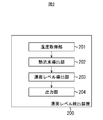
- FIG. 2 is a diagram showing an example of a functional configuration of the molten metal level detecting device in the continuous casting mold.
- FIG. 3A is a diagram showing an example of a two-dimensional cross section of space x-time t in the coordinate system of the unsteady heat transfer inverse problem.
- FIG. 3B is a diagram illustrating an example of a two-dimensional section of the space x-space y of the coordinate system of the unsteady heat transfer inverse problem.
- FIG. 4 is a flowchart for explaining an example of the operation of the hot water level detecting device.
- FIG. 4 is a flowchart for explaining an example of the operation of the hot water level detecting device.
- FIG. 5 is a diagram illustrating an example of a hardware configuration of the hot water surface level detection apparatus.
- FIG. 6 is a diagram illustrating the position of the thermocouple in the example.
- FIG. 7A is a diagram conceptually illustrating an example of the relationship between the value of the y-axis direction component of the heat flux vector on the inner wall surface of the mold and the position in the y-axis direction.
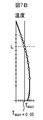
- FIG. 7B is a diagram conceptually showing the relationship between the temperature in the mold and the position in the y-axis direction.
- FIG. 8 is a diagram showing an example of the configuration of an apparatus for actually measuring the hot water level.
- FIG. 9 is a diagram showing a hot water level detected in the invention example, a hot water level detected by an existing method, and an actually measured hot water level.
- FIG. 1 is a diagram illustrating an example of a configuration of a molten metal level detection system in a continuous casting mold.
- FIG. 1 shows a cross section of a continuous casting machine cut along its height direction (y-axis direction).
- the continuous casting machine includes a tundish 11, an immersion nozzle 12, a mold (mold) 13, and pinch rolls 14a to 14d.
- the continuous casting machine can be realized by a known technique. Therefore, detailed description of the continuous casting machine is omitted here.
- the tundish 11 temporarily stores the molten steel (metal melt) M supplied from the ladle.
- the mold 13 is disposed below the tundish 11 with a space from the tundish 11.
- the mold 13 has, for example, two short sides 13a and 13b and two long sides.
- the two short sides 13a and 13b are arranged with a gap so as to face each other in the width direction (x-axis direction).
- the two long sides are arranged with a distance so as to face each other in the depth direction (direction perpendicular to the x-axis and the y-axis).
- a region surrounded by the two long sides and the two short sides 13a and 13b is a hollow rectangular parallelepiped region. This area becomes an area inside the mold 13.
- a groove is formed on the outer wall surface of the mold 13.
- the casting mold 13 is cooled by flowing cooling water through the groove. In FIG. 1, only the short side portion of the long side portion and the short side portion is shown for convenience of description.
- the immersion nozzle 12 injects the molten steel M stored in the tundish 11 into the mold 13.
- the immersion nozzle 12 is disposed such that its base end is located on the bottom surface of the tundish 11 and a predetermined region on the distal end side is located inside the mold 13. Moreover, the inside of the immersion nozzle 12 and the inside of the tundish 11 communicate with each other.
- the supply amount of the molten steel M supplied from the tundish 11 to the immersion nozzle 12 is adjusted by a sliding nozzle or a stopper.
- a plurality of pairs of pinch rolls 14a to 14d are disposed along the steel conveyance path drawn downward from the mold 13. In FIG. 1, only two pairs of pinch rolls 14a to 14d are shown. However, in practice, more pinch rolls are arranged according to the length of the transport path.
- a plurality of cooling sprays are arranged outside the pinch rolls 14a to 14d. The plurality of cooling sprays inject cooling water for cooling the steel drawn downward from the mold 13 onto the steel.
- the injected molten steel inside the mold 13 is cooled by the mold 13, and solidified shells 15a and 15b are formed from the surface to solidify.
- Steel whose surfaces are solidified shells 15a and 15b but whose interior is not solidified is continuously drawn out from the lower end of the mold 13 while being sandwiched between pinch rolls 14a to 14d.
- the steel is solidified to the inside by advancing cooling of the steel with the cooling water sprayed from the cooling spray.
- the steel thus solidified is cut into a predetermined size on the downstream side of the continuous casting machine, and slabs having different cross-sectional shapes such as slabs, blooms and billets are produced.
- the powder 17 is added to the molten steel inside the mold 13 as needed.
- the thin film of the powder 17 exists between the inner wall surface of the mold 13 and the solidified shells 15 a and 15 b in addition to the surface of the molten steel inside the mold 13.
- the solidified shells 15a and 15b in the vicinity of the meniscus in the mold 13 are uniformly generated, thereby preventing surface cracks of the solidified shells 15a and 15b and preventing seizure of the mold 13 and the solidified shells 15a and 15b. To do.
- a plurality of thermocouples 18 are embedded in the mold 13 along the casting direction (y-axis direction).
- the number of the plurality of thermocouples 18 is preferably 3 or more.
- the number of the plurality of thermocouples 18 and the interval between the two thermocouples 18 adjacent to each other can be determined according to the calculation accuracy of heat flux described later.
- the plurality of thermocouples 18 are embedded in a region that is relatively close to the inner wall surface among the inner wall surface and the outer wall surface of the mold 13.
- the plurality of thermocouples 18 do not necessarily have to be embedded in such a region as long as they are embedded in the mold 13. As shown in FIG.
- thermocouples 18 are embedded in the short side portion 13a
- a plurality of thermocouples may be embedded in at least one of the short side portion 13b and the two long side portions.
- the inner wall surface of the mold 13 is called an operating surface
- the outer wall surface is called a water-cooled surface.
- the surface in contact with the molten steel is the working surface.
- template 13 is an operation surface.
- FIG. 2 is a diagram illustrating an example of a functional configuration of the molten metal level detecting device 200 in the continuous casting mold.
- the molten metal level detecting device in the continuous casting mold is abbreviated as a molten metal level detecting device as necessary.
- the hot water surface level detection apparatus 200 performs unsteady heat transfer inverse problem analysis using the temperatures measured by the plurality of thermocouples 18.
- the unsteady heat transfer inverse problem is based on the unsteady heat conduction equation that governs the calculation region, and the boundary conditions such as the temperature and heat flux at the region boundary or the initial condition based on the temperature information inside the region.
- the unsteady heat transfer order problem refers to a problem of estimating temperature information inside a region based on a known boundary condition.
- the molten metal surface level detection device 200 uses the interpolated temperature function obtained by performing the unsteady heat transfer inverse problem analysis, and the y-axis direction of the heat flux vector on the inner wall surface of the mold 13 (the casting direction of the mold 13). Calculate component values.
- the extrapolated temperature function is a function indicating the temperature of the mold 13 at the position (x, y) and time t.
- the hot water level detecting device 200 detects the hot water level based on the value of the y-axis direction component of the heat flux vector on the inner wall surface of the mold 13.
- the molten metal level is the height position (position in the y-axis direction) of the surface of the molten steel in the mold 13.
- the role of the mold 13 is to cool and solidify the molten steel. For this reason, when examining detecting the molten metal surface level by performing an unsteady heat transfer inverse problem analysis, attention is paid to the behavior of the heat flux in the x-axis direction (the heat removal direction of the mold 13). The behavior of the heat flux in the direction (the casting direction of the mold 13) has not been noticed. Further, the value of the y-axis direction component of the heat flux vector is smaller than the value of the x-axis direction component.
- the hot water level detecting device 200 of the present embodiment has been realized.
- an example of a specific configuration of the hot water level detection device 200 of the present embodiment will be described.
- the hot water surface level detection apparatus 200 includes a temperature acquisition unit 201, a heat flux deriving unit 202, a heat flux deriving unit 202, and a hot water surface level deriving unit 203.
- ⁇ Temperature acquisition unit 201> The temperature acquisition unit 201 inputs the temperature [K] measured by the plurality of thermocouples 18 and outputs the temperature measured by the plurality of thermocouples 18 at the same time.
- the temperature acquisition unit 201 outputs such a temperature at every predetermined sampling time. For example, the temperature acquisition unit 201 inputs and outputs the temperatures measured by the plurality of thermocouples 18 every time the sampling time elapses.
- ⁇ Heat flux deriving unit 202> Based on the temperature output from the temperature acquisition unit 201, the casting direction (y-axis direction) of the mold 13 minus the heat removal is used as an extrapolation temperature function u ⁇ (x, y, t) for estimating the temperature of the mold 13. This is a mathematical expression for predicting the time change of the temperature distribution of the two-dimensional cross section in the direction (x-axis direction).
- FIG. 3A is a diagram showing an example of a coordinate system for an unsteady heat transfer inverse problem.
- FIG. 3A shows a definition point of information amount on a two-dimensional cross section of space x-time t at a certain position in the y-axis direction.
- FIG. 3B is also a diagram illustrating an example of a coordinate system for the unsteady heat transfer inverse problem.
- FIG. 3B shows the definition points of the information amount on the two-dimensional cross section of the space x-space y at a certain time t.
- 3A and 3B show two-dimensional cross sections of the same three-dimensional coordinates (space x-space y-time t coordinates).
- the x axis and the y axis are spatial axes.
- the t axis is a time axis.
- the plots indicated by black circles are information content definition points.
- the definition point of the information amount indicates the position of the thermocouple 18 and the time when the temperature is measured by the thermocouple 18.
- the amount of information at this definition point includes the temperature measured by the thermocouple 18.
- Plots indicated by broken lines are also information amount defining points.
- the definition point of the information amount indicates the position on the outer wall surface of the mold 13 and the time when the heat flux on the outer wall surface is estimated.
- a case where there is no temperature measuring means such as a thermocouple on the outer wall surface of the mold 13 will be described as an example. Accordingly, the information amount of the defining point, the heat flux which is determined and a heat transfer coefficient ⁇ and a water temperature u w between the material and the water constituting the mold 13 as known.
- plots indicated by black circles and plots indicated by broken lines are defined as information amount definition points. That is, points on the three-dimensional coordinates of the x-axis-y-axis-t-axis shown by the plots indicated by black circles and the broken lines shown in FIG. 3A, and the plots indicated by black circles and the broken lines shown in FIG. 3B. Each becomes a defining point of information amount.
- the timing t N is timing when the latest temperature was measured at a plurality of thermocouples 18.
- the heat flux deriving unit 202 sets the definition point of the information amount including the oldest temperature measurement timing among the seven temperature measurement timings. Exclude from the definition point of information amount. Then, the heat flux deriving unit 202 adds the information amount definition points including the latest temperature measurement timing to the seven information amount definition points. Note that the number of times t that define the definition point of the information amount is not limited to seven.
- FIG. 3B shows an example in which a plurality of thermocouples 18 are arranged at equal intervals along the y-axis direction. However, the interval between two thermocouples adjacent to each other may not be equal. Further, the number of the plurality of thermocouples 18 is not limited to seven.
- the heat flux deriving unit 202 derives a weight vector ⁇ j included in the extrapolated temperature function u ⁇ (x, y, t) based on the information amount at the definition point of the above information amount.
- a weight vector ⁇ j included in the extrapolated temperature function u ⁇ (x, y, t) based on the information amount at the definition point of the above information amount.
- a is the square root of the thermal diffusion coefficient [m 2 / s] of the material constituting the mold.
- 0 ⁇ x ⁇ 1 and 0 ⁇ y ⁇ 1 indicate that the coordinates (x, y) of the x axis and the y axis are normalized by [0, 1]. That is, the respective x-axis coordinates are determined so that the x-axis coordinate on the inner wall surface of the mold 13 is “0” and the x-axis coordinate on the outer wall surface is “1”. Further, the y-axis coordinates are determined so that the y-axis coordinate at the upper end of the mold 13 is “0” and the y-axis coordinate at the lower end is “1”.
- the boundary condition on the outer wall surface (cooling surface) of the mold 13 is expressed by the following equation (2).
- ⁇ is the thermal conductivity [W / mk] of the material constituting the mold 13.
- the water temperature u w , the heat transfer coefficient ⁇ between the material constituting the mold 13 and water, and the thermal conductivity ⁇ of the material constituting the mold 13 are all preset values.
- the water temperature u w for example, can be used an average value of a predetermined time.
- the expression (2) is an expression showing the balance of heat fluxes on the outer wall surface of the mold 13. That is, the equation (2) is an equation indicating that the following first heat flux and second heat flux are equal.
- the first heat flux is a heat flux based on the temperature gradient in the heat removal direction of the mold 13 on the outer wall surface of the mold 13 and the thermal conductivity ⁇ of the material constituting the mold 13.
- the second heat flux is based on the difference between the temperature u (1, y, t) on the outer wall surface of the mold 13 and the water temperature u w and the heat transfer coefficient ⁇ between the material constituting the mold 13 and water. Heat flux.
- the thermocouple temperature function u (x * , y * , t) is expressed by the following equation (3).
- thermocouple temperature function u (x * , y * , t) is a function indicating the temperature measured by the thermocouple 18 and is a function of the position (x, y) of the thermocouple 18 and the time t.
- h (t) is the temperature at time t measured by the thermocouple 18.
- the x-axis coordinate of the thermocouple 18 is determined so that the x-axis coordinate on the inner wall surface of the mold 13 is “0” and the x-axis coordinate on the outer wall surface is “1”. Further, the y-axis coordinate of the thermocouple 18 is determined so that the y-axis coordinate at the upper end of the mold 13 is “0” and the y-axis coordinate at the lower end is “1”.
- the extrapolated temperature function u ⁇ (x, y, t) is expressed by the following equation (4).
- the extrapolated temperature function u ⁇ (x, y, t) is a temperature that satisfies the two-dimensional unsteady heat conduction equation represented by equation (1), and is an approximate solution of the temperature u.
- x j and y j are elements (x-axis coordinates, y-axis coordinates) of an arbitrary reference position vector (x j , y j ).
- t j is an arbitrary reference time.
- a point on the three-dimensional coordinate determined by the reference position vector (x j , y j ) and the reference time t j is called a center point.
- the reference position vector (x j , y j ) and the reference time t j are made to coincide with the information amount definition point described above.
- the reference position vector (x j , y j ) and the reference time t j do not have to coincide with the information amount definition points described above.
- j is a variable for identifying the above-described center point (a point on a three-dimensional coordinate determined by the reference position vector (x j , y j ) and an arbitrary reference time t j ), and is an integer in the range of 1 to m + 1. is there.
- n p1 is the number of center points j on the outer wall surface of the mold 13.
- the center point j on the outer wall surface of the mold 13 is set so that the internal / extrapolated temperature function u ⁇ (x, y, t) satisfies the expression (2)
- n p2 is the position of the thermocouple 18.
- the position of the thermocouple 18 is set so that the extrapolated temperature function u ⁇ (x, y, t) satisfies the expression (3).
- n t is the number of times.
- This time is set so that the extrapolated temperature function u ⁇ (x, y, t) satisfies the expressions (2) and (3).
- m is the number of center points j determined by the position on the outer wall surface of the mold 13 and the time.
- l is the number of center points j determined by the position of the thermocouple 18 and the time.
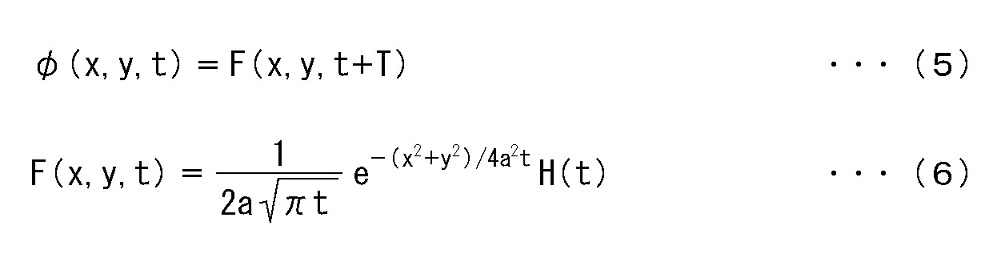
- ⁇ ( xxj , yyj , ttj ) is a basis function determined by the following equations (5) and (6).
- Equation (6) H (t) is a snake side function.
- Equation (6) is an equation expressed in the form of a basic solution that satisfies the two-dimensional unsteady heat conduction equation shown in Equation (1).
- the basic solution is a solution (temperature u) of a two-dimensional unsteady heat conduction equation when the initial condition of the temperature u is expressed by a ⁇ function.
- T is a parameter for adjusting the diffusion profile of the basic solution of the two-dimensional unsteady heat conduction equation, and is set in advance. T is a value greater than zero.
- the basis functions ⁇ (x-x j, y -y j, t-t j) , the center point j when the (reference vector (x j, y j) and the reference time t j) based on the Is a function expressed in the form of a basic solution that satisfies the two-dimensional unsteady heat conduction equation.
- lambda j is a weight vector representing the weight of the basis function ⁇ (x-x j, y -y j, t-t j) of the inner and outer ⁇ degree function u ⁇ (x, y, t ).
- the weight vector ⁇ j depends on the influence of the basis function ⁇ (xx j , y ⁇ y j , t ⁇ t j ) on the extrapolated temperature function u ⁇ (x, y, t) and the basis function ⁇ (x ⁇ x j , y ⁇ y j , t ⁇ t j ) and other extrapolated temperature functions u ⁇ (x, y, t) of other basis functions ⁇ (x ⁇ x j , y ⁇ y j , t ⁇ t j ) It is determined by the balance with the influence on A basis function ⁇ (xx j , yy j , tt j ) exists for each central point j, and a weight vector
- the inner and outer ⁇ degree function u ⁇ (x, y, t ) is a basis function ⁇ (x-x j, y -y j, t-t j) of the product of and the weight vector lambda j, the center point It is represented by the sum of values in each of j.
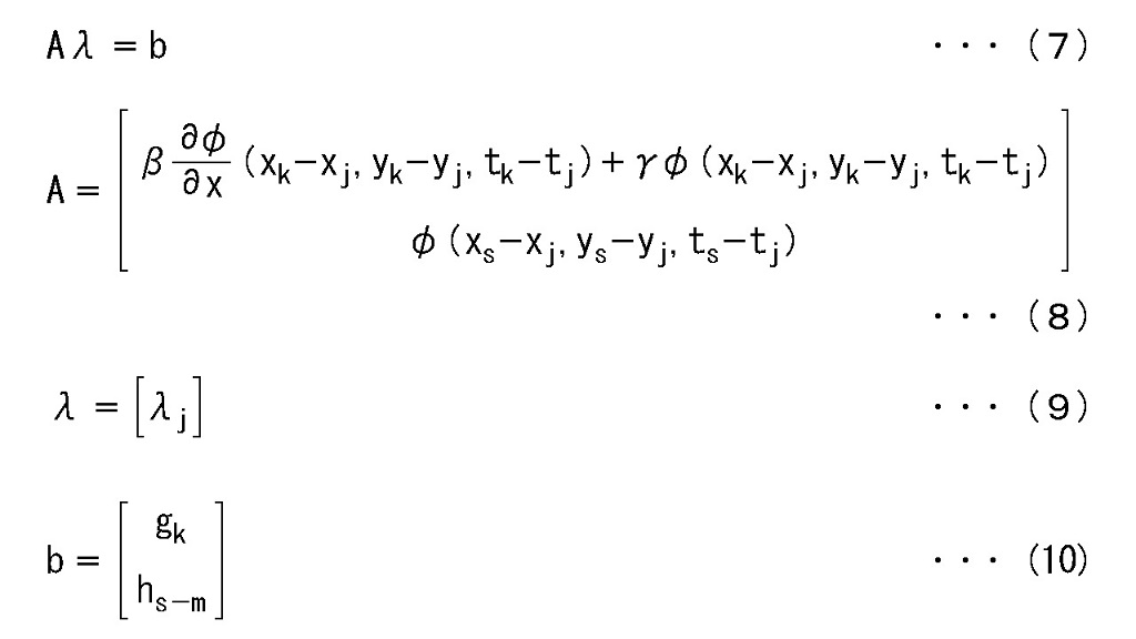
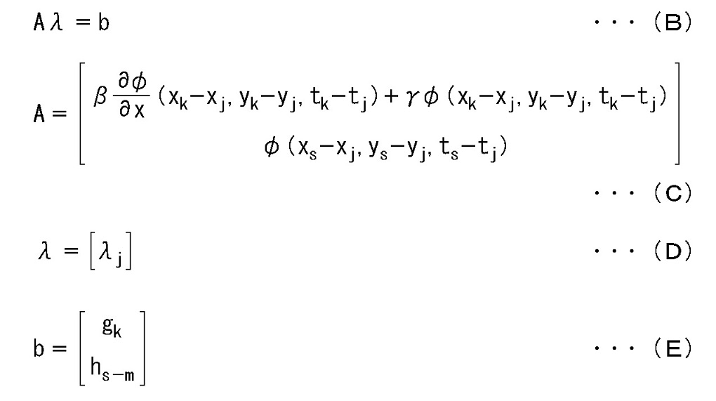
- the weight vector ⁇ j is expressed by the following equations (7) to (10).
- the matrix A is an (m + 1) ⁇ (m + 1) matrix.
- b and ⁇ are (m + 1) dimensional column vectors. As described above, (m + 1) is the number of center points j.
- G k in [] represents k row components of the matrix b.
- the h s ⁇ m in [] represents the s row component of the matrix b.
- m is represented by n p1 ⁇ n t.
- n p1 is the number of center points j on the outer wall surface of the mold 13.
- the x-axis coordinate is determined so that the x-axis coordinate on the inner wall surface of the mold 13 is “0” and the x-axis coordinate on the outer wall surface is “1”. Therefore, in the equation (8), x k is “1”.
- Equations (7) to (10) are expressed by two-dimensional unsteady heat conduction equation of equation (1), boundary conditions on the outer wall surface of mold 13 of equation (2), thermocouple temperature function of equation (3) (each position) (X * , y * ) ⁇ temperature measured by the thermocouple inside the mold 13 at each time t), and information on the definition point of the information amount so as to satisfy the extrapolated temperature function of equation (4) , (2) and (4) are substituted into the simultaneous equations, and the simultaneous equations are solved to derive the weight vector ⁇ j .
- Information on the definition point of the information amount to be substituted into the simultaneous equations includes the position of the definition point of the information amount, the temperature of the thermocouple 18, the measurement timing of the temperature of the thermocouple 18, the water temperature u w , and the material constituting the mold 13.
- the thermal conductivity ⁇ , the heat transfer coefficient ⁇ of the material constituting the mold 13 and water, and the thermal diffusion coefficient a of the material constituting the mold 13 are included.
- the definition point of the information amount for the water temperature u w , the thermal conductivity ⁇ of the material composing the mold 13, the heat transfer coefficient ⁇ of the material composing the mold 13 and water, and the thermal diffusion coefficient a of the material composing the mold 13 May be different or may be the same. Further, when solving the simultaneous equations of the equations (2) and (4), the position of the center point j is also substituted into the simultaneous equations.
- the heat flux deriving unit 202 derives the weight vector ⁇ j by the equations (7) to (10) as described above.
- the heat flux deriving unit 202 performs the above process every time the temperature is acquired from the temperature acquisition unit 201.
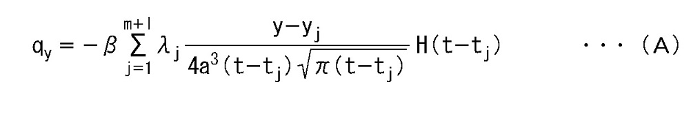
- the value q y of the y-axis direction component of the heat flux vector is expressed by the following equation (11).
- the heat flux deriving unit 202 includes the thermal conductivity ⁇ of the material constituting the mold 13, the thermal diffusion coefficient a of the material constituting the mold 13, the reference time t j , the number m + 1 of the center points j, and the above
- the value q y of the y-axis direction component of the heat flux vector on the inner wall surface of the mold 13 is derived by substituting the weight vector ⁇ j derived as described above into the equation (11).
- the position at which the value q y of the y-axis direction component of the heat flux vector on the inner wall surface of the mold 13 is the minimum is the molten metal surface level.
- the position where the value q y of the y-axis direction component of the heat flux vector on the inner wall surface of the mold 13 is the maximum is the hot water surface level.
- the molten metal surface level deriving unit 203 determines that the y-axis component value q y of the heat flux vector in which the y-axis component vector is opposite to the casting direction (that is, the normal direction of the molten metal surface).
- the position where the absolute value of is the maximum is derived as the hot water level.
- the output unit 204 outputs information on the hot water level derived by the hot water level derivation unit 203.
- As an output form of the information on the molten metal level at least one of display on a computer display, storage in a storage medium or portable storage medium of the molten metal level detection device 200, and transmission to an external device is used. Can be adopted.
- step S401 the temperature acquisition unit 201 acquires temperatures measured by the plurality of thermocouples 18.
- the heat flux deriving unit 202 determines whether or not the number of temperatures necessary for deriving the weight vector ⁇ j has been acquired. Specifically, the heat flux deriving unit 202 waits until 1 temperature is acquired as the number of information amount definition points for the thermocouple 18. In the example shown in FIGS. 3A and 3B, the heat flux deriving unit 202 has seven information amount definition points in the y-axis direction and 49 information amount definition points in the t-axis direction. Wait until the temperature is acquired. When 49 temperatures have already been acquired, if the temperatures corresponding to the seven information amount definition points in the y-axis direction are acquired at the same time, the heat flux deriving unit 202 is the same. Among the temperatures corresponding to the seven definition points of the information amount in the y-axis direction, the temperature at the oldest time is deleted, and the temperature acquired this time is added.
- step S401 if the number of temperatures necessary for deriving the weight vector ⁇ j has not been acquired, the process returns to step S401. Then, the processes in steps S401 and S402 are repeated until the number of temperatures necessary for deriving the weight vector ⁇ j is acquired. When the number of temperatures necessary for deriving the weight vector ⁇ j is acquired, the process proceeds to step S403.
- step S403 the heat flux deriving unit 202 derives the weight vector ⁇ j using the equations (7) to (10).
- step S404 the heat flux deriving unit 202 derives a value q y of the y-axis direction component of the heat flux vector on the inner wall surface of the mold 13 by the equation (11).
- step S405 the molten metal surface level deriving unit 203 derives the relationship between the y-axis direction component value q y of the heat flux vector and the y-axis direction position. Based on the derived relationship, the molten metal surface level deriving unit 203 sets, as the molten metal surface level, the position where the value q y of the y-axis direction component of the heat flux vector has a negative value and the absolute value is maximum (ie, minimum). To derive.
- step S ⁇ b> 406 the output unit 204 outputs information on the molten metal level derived by the molten metal level derivation unit 203.
- step S407 the hot water surface level detection device 200 determines whether or not to end the derivation of the hot water surface level. This determination is performed based on, for example, an operation by the operator with respect to the hot water level detecting device 200.
- step S401 the process returns to step S401. Then, every time a new temperature is acquired in step S401, the processes in steps S402 to S407 are repeated. On the other hand, when the derivation of the hot water surface level is finished, the processing according to the flowchart of FIG. 4 is finished.
- FIG. 5 is a diagram illustrating an example of a hardware configuration of the hot water surface level detection apparatus 200.
- the hot water level detection device 200 includes a CPU (Central Processing Unit) 501, a ROM (Read Only Memory) 502, a RAM (Random Access Memory) 503, a PD (Pointing Device) 504, An HD (Hard Disk) 505, a display device 506, a speaker 507, an I / F (Interface) 508, and a system bus 509 are included.
- a CPU Central Processing Unit
- ROM Read Only Memory
- RAM Random Access Memory
- PD Pointing Device
- An HD Hard Disk
- display device 506 a speaker 507
- I / F Interface
- the CPU 501 comprehensively controls the operation in the hot water level detecting device 200.
- the CPU 501 controls each component (502 to 508) of the hot water level detection device 200 via the system bus 509.
- the ROM 502 stores a basic input / output system (BIOS) and an operating system program (OS), which are control programs for the CPU 501, programs necessary for the CPU 501 to execute the processing according to the flowchart shown in FIG.
- BIOS basic input / output system
- OS operating system program
- the RAM 503 functions as a main memory, work area, and the like for the CPU 501.
- the CPU 501 loads various computer programs and information from the ROM 502 and the HD 505 into the RAM 503, and executes various processes by executing the processing on the computer program and the information.
- a computer program that executes the processing of the flowchart of FIG. 4 described above may be stored in the HD 505.
- the PD 504 includes, for example, a mouse, a keyboard, and the like, and constitutes an operation input unit for an operator to input an operation to the hot water surface level detection device 200 as necessary.
- the HD 505 constitutes storage means for storing various information, data, files, and the like.
- the display device 506 constitutes display means for displaying various information and images based on the control of the CPU 501.
- the speaker 507 constitutes an audio output unit that outputs audio related to various types of information based on the control of the CPU 501.
- the I / F 508 communicates various types of information with an external device based on the control of the CPU 501.
- the temperature measured by the thermocouple 18 is input to the molten metal level detection device 200 via the I / F 508.
- a system bus 509 is a bus for connecting the CPU 501, the ROM 502, the RAM 503, the PD 504, the HD 505, the display device 506, the speaker 507, and the I / F 508 so that they can communicate with each other.
- thermocouples 18 are embedded in the short side portion 13 a of the mold 13. As shown in FIG. 6, it is not necessary to embed a plurality of thermocouples 18 in the mold 13 accurately along the y-axis direction. However, the aforementioned weight vector ⁇ j is derived with the x-axis coordinate of each thermocouple 18 set to the same value. That is, the position in the x-axis direction of each thermocouple 18 may not be exactly the same as long as the accuracy of the weight vector ⁇ j is not affected.
- template 13 were measured, the average value was calculated, and it was set as the temperature of cooling water.
- the value q y of the y-axis direction component of the heat flux vector on the inner wall surface of the mold 13 is derived.
- the judges, the heat flux vector y axis component vector is opposite to the casting direction, the position at which the absolute value is maximum value q y in the y-axis direction component and bath level level L.
- FIG. 7A conceptually shows an example of the relationship between the value q y of the y-axis direction component of the heat flux vector on the inner wall surface of the mold 13 and the position in the y-axis direction obtained by the method of the present embodiment.
- FIG. 7B conceptually shows an example of the relationship between the temperature in the mold 13 and the position in the y-axis direction obtained by an existing method.
- the hot water level was measured using the apparatus shown in FIG.
- a float 801 is floated on the molten steel surface in the mold, and a rod 802 is disposed on the float 801.
- an oscillation measurement jig 803 is arranged.
- the movement of the tip of the rod 802 and the movement of the tip of the oscillation measuring jig 803 are photographed by the video camera 804.
- the displacement of the molten metal surface in the y-axis direction is digitized and recorded. From the displacement of the molten metal surface in the y-axis direction, the molten metal surface level was determined.
- FIG. 9 shows the molten metal level detected by the method of the present embodiment, the molten metal level detected by the existing method, and the measured molten metal level.
- the horizontal axis represents time, and the vertical axis represents the hot water level.
- the measurement accuracy of the molten metal level is about 5 to 10 mm, it can be said that the molten metal level detected by the method of the present embodiment has a good correspondence with the measured molten metal level.
- the molten metal level is detected by detecting the influence of heat transfer at the molten metal surface position of the molten steel in the mold 13, which is heat removal by the powder 17. That is, the position at which the absolute value of the y-axis direction component value q y of the heat flux vector in which the y-axis component vector is opposite to the casting direction is derived as the oil level. Therefore, the detection accuracy of the hot water level can be increased. This makes it possible to stably control the molten metal surface level, prevent molten steel overflow, entrainment of suspended matter, etc., and improve the internal quality of the slab. Furthermore, it contributes to operational stability and quality improvement, such as perforation trouble due to local melting of the immersion nozzle 12, prevention of the tip of the immersion nozzle 12 from dropping, and improvement in detection accuracy of the drift of molten steel in the mold 13. .
- a value obtained by multiplying a value obtained by partially differentiating the interpolating function u ⁇ (x, y, t) continuously taking a value by y is multiplied by the thermal conductivity ⁇ of the material constituting the mold 13. Derived as a value q y of the y-axis direction component of the heat flux vector. Therefore, the calculation accuracy of the heat flux can be improved as compared with the case where the heat flux is derived as a discrete value.
- the interpolation function u ⁇ (x, y, t) is the sum of the products of the basis function ⁇ (xx j , yy j , tt j ) and the weight vector ⁇ j.
- Weights are defined by using the interpolated function u ⁇ (x, y, t) expressed in this way and the boundary condition representing the balance of heat fluxes on the outer wall surface of the mold 13 of the two-dimensional unsteady heat conduction equation as simultaneous equations.
- a vector ⁇ j is derived. Therefore, the thermocouple to be used can be only a plurality of thermocouples arranged in a line along the y-axis direction. That is, it is not necessary to arrange a plurality of rows of thermocouples in the x-axis direction.
- the present invention can be used to detect the level of molten steel in a continuous casting mold.
Landscapes
- Physics & Mathematics (AREA)
- Engineering & Computer Science (AREA)
- Mechanical Engineering (AREA)
- Thermal Sciences (AREA)
- Fluid Mechanics (AREA)
- General Physics & Mathematics (AREA)
- Continuous Casting (AREA)
- Measurement Of Levels Of Liquids Or Fluent Solid Materials (AREA)
Abstract
Description
図1は、連続鋳造鋳型内の湯面レベル検出システムの構成の一例を示す図である。図1は、連続鋳造機を、その高さ方向(y軸方向)に沿って切った断面を示す。
図1において、連続鋳造機は、タンディッシュ11と、浸漬ノズル12と、鋳型(モールド)13と、ピンチロール14a~14dと、を有する。尚、連続鋳造機は、公知の技術で実現できる。したがって、ここでは、連続鋳造機の詳細な説明を省略する。
鋳型13は、タンディッシュ11と間隔を有して、タンディッシュ11の下方に配置される。鋳型13は、例えば、2つの短辺部13a、13bと、2つの長辺部と、を有する。2つの短辺部13a、13bは、幅方向(x軸方向)において相互に対向するように間隔を有して配置される。2つの長辺部は、奥行き方向(x軸およびy軸と垂直な方向)において相互に対向するように間隔を有して配置される。2つの長辺部と2つの短辺部13a、13bにより囲まれる領域は、中空の直方体形状の領域になる。この領域が、鋳型13の内部の領域になる。また、鋳型13の外壁面には、溝が形成される。この溝に冷却水を流すことにより、鋳型13は水冷される。尚、図1では、表記の都合上、長辺部と短辺部のうち、短辺部のみを示す。
図2は、連続鋳造鋳型内の湯面レベル検出装置200の機能的な構成の一例を示す図である。連続鋳造鋳型内の湯面レベル検出装置を必要に応じて湯面レベル検出装置と略称する。
湯面レベル検出装置200は、複数の熱電対18により測定された温度を用いて、非定常伝熱逆問題解析を行う。ここで、非定常伝熱逆問題とは、計算領域を支配する非定常熱伝導方程式を基にして、領域内部の温度情報を既知として領域境界での温度や熱流束などの境界条件または初期条件を推定する問題を指す。これに対して、非定常伝熱順問題は、既知である境界条件を基にして、領域内部の温度情報を推定する問題を指す。
<温度取得部201>
温度取得部201は、複数の熱電対18で測定された温度[K]を入力し、複数の熱電対18で同じ時刻に測定された温度を出力する。温度取得部201は、このような温度の出力を所定のサンプリング時間ごとに行う。例えば、温度取得部201は、サンプリング時間が経過する度に、複数の熱電対18で測定された温度を入力して出力する。
鋳型13の温度を推定するための内外挿温度関数u^(x,y,t)を、温度取得部201から出力された温度に基づいて、鋳型13の鋳造方向(y軸方向)-抜熱方向(x軸方向)の2次元断面の温度分布の時間変化を予測する数式とする。
ここで、内外挿温度関数u^(x,y,t)の一例について説明する。
まず、2次元非定常熱伝導方程式は、以下の(1)式で表される。

鋳型13の外壁面(冷却面)における境界条件は、以下の(2)式で表される。

本実施形態では、熱電対温度関数u(x*,y*,t)を以下の(3)式で表す。

本実施形態では、内外挿温度関数u^(x,y,t)を以下の(4)式で表す。

np1は、鋳型13の外壁面における中心点jの数である。鋳型13の外壁面における中心点jは、内外挿温度関数u^(x,y,t)が(2)式を満足するように設定される、np2は、熱電対18の位置である。熱電対18の位置は、内外挿温度関数u^(x,y,t)が(3)式を満足するように設定される。ntは、時刻の数である。この時刻は、内外挿温度関数u^(x,y,t)が(2)式および(3)式を満足するように設定される。以上のように、mは、鋳型13の外壁面における位置と時刻とにより定まる中心点jの数である。また、lは、熱電対18の位置と時刻とにより定まる中心点jの数である。
重みベクトルλjは、以下の(7)式~(10)式で表される。
行列Aは、(m+l)×(m+l)行列である。bおよびλは、(m+l)次元列ベクトルである。前述したように、(m+l)は、中心点jの数である。
熱流束導出部202は、温度取得部201から温度を取得する度に、以上の処理を行う。
本実施形態では、熱流束ベクトルのy軸方向成分の値qyは、以下の(11)式で表される。

湯面レベル導出部203は、熱流束導出部202で導出された熱流束ベクトルのy軸方向成分の値qyから、熱流束ベクトルのy軸方向成分の値qyとy軸方向の位置との関係を導出する。湯面レベル導出部203は、この関係から、熱流束ベクトルのy軸方向成分の値qyが負の値を有し且つ絶対値が最大(すなわち最小)となる位置を、湯面レベルとして導出する。本実施形態では、図1に示すようにy軸を定義する。したがって、鋳型13の内壁面における熱流束ベクトルのy軸方向成分の値qyが最小(負の値のうち絶対値が最大)となる位置が湯面レベルになる。尚、図1に示す向きとは逆向きにy軸を定義した場合、鋳型13の内壁面における熱流束ベクトルのy軸方向成分の値qyが最大となる位置が湯面レベルになる。このように、湯面レベル導出部203は、y軸成分ベクトルが鋳造方向とは逆向きとなる(すなわち、湯面の法線方向を向く)熱流束ベクトルの、y軸方向成分の値qyの絶対値が最大となる位置を湯面レベルとして導出する。
出力部204は、湯面レベル導出部203により導出された湯面レベルの情報を出力する。湯面レベルの情報の出力形態としては、コンピュータディスプレイへの表示、湯面レベル検出装置200の内部の記憶媒体や可搬型記憶媒体への記憶、および外部装置への送信のうち、少なくとも1つを採用することができる。
次に、図4のフローチャートを参照しながら、本実施形態の湯面レベル検出装置200の動作の一例を説明する。
ステップS401において、温度取得部201は、複数の熱電対18で測定された温度を取得する。
次に、ステップS404において、熱流束導出部202は、(11)式により、鋳型13の内壁面における熱流束ベクトルのy軸方向成分の値qyを導出する。
次に、ステップS407において、湯面レベル検出装置200は、湯面レベルの導出を終了するか否かを判定する。この判定は、例えば、湯面レベル検出装置200に対するオペレータによる操作に基づいて行われる。
一方、湯面レベルの導出を終了する場合には、図4のフローチャートによる処理を終了する。
図5は、湯面レベル検出装置200のハードウェア構成の一例を示す図である。
図5に示すように、湯面レベル検出装置200は、CPU(Central Processing Unit)501と、ROM(Read Only Memory)502と、RAM(Random Access Memory)503と、PD(Pointing Device)504と、HD(Hard Disk)505と、表示装置506と、スピーカ507と、I/F(Interface)508と、システムバス509とを有する。
ROM502は、CPU501の制御プログラムであるBIOS(Basic Input/Output System)やオペレーティングシステムプログラム(OS)、CPU501が、前述した図4に示すフローチャートによる処理を実行するために必要なプログラム等を記憶する。
PD504は、例えば、マウスやキーボード等からなり、操作者が必要に応じて、湯面レベル検出装置200に対して操作入力を行うための操作入力手段を構成する。
HD505は、各種の情報やデータ、ファイル等を記憶する記憶手段を構成する。
表示装置506は、CPU501の制御に基づいて、各種の情報や画像を表示する表示手段を構成する。
スピーカ507は、CPU501の制御に基づいて、各種の情報に係る音声を出力する音声出力手段を構成する。
システムバス509は、CPU501、ROM502、RAM503、PD504、HD505、表示装置506、スピーカ507およびI/F508を相互に通信可能に接続するためのバスである。
本実施形態の手法で検出した湯面レベルと、既存の手法で検出した湯面レベルと、実測の湯面レベルとを比較した。図6に示すように、複数の熱電対18は、鋳型13の短辺部13aに埋設される。図6に示すように、正確にy軸方向に沿って複数の熱電対18を鋳型13に埋設する必要はない。ただし、各熱電対18のx軸の座標を同じ値として、前述した重みベクトルλjを導出する。すなわち、重みベクトルλjの精度に影響がない範囲であれば、各熱電対18のx軸方向の位置は、厳密に同じでなくてもよい。また、鋳型13の入り側(上側)の水温と鋳型13の出側(下側)の水温を測定してその平均値を計算して冷却水の温度とした。
既存の手法では、実測の湯面レベルが高くなると検出精度が極端に低下し、実測値に追従できなくなっている。
それに対して、本実施形態の手法では、広範囲に亘り実測値を追従できているのが分かる。湯面レベルの実測精度が5~10mm程度のバラツキがあることを勘案すると、本実施形態の手法により検出した湯面レベルは実測の湯面レベルと良い対応関係にあるといえる。
Claims (9)
- 連続鋳造鋳型の鋳造方向に沿って当該連続鋳造鋳型内に埋設された複数の温度測定手段により測定された温度を取得する温度取得手段と、
前記温度取得手段で導出された温度から非定常伝熱逆問題解析を行った結果に基づいて、前記連続鋳造鋳型の内壁面における熱流束ベクトルの前記鋳造方向成分の値を導出する熱流束導出手段と、
前記熱流束導出手段で導出された、前記連続鋳造鋳型の内壁面における熱流束ベクトルの前記鋳造方向成分の値に基づいて、前記連続鋳造鋳型の内部の湯面レベルを導出する湯面レベル導出手段と、を有し、
前記湯面レベル導出手段は、前記鋳造方向成分のベクトルが前記鋳造方向とは逆向きとなる前記熱流束ベクトルの、前記鋳造方向成分の値の絶対値が最大となる位置を前記湯面レベルとして導出することを特徴とする連続鋳造鋳型内の湯面レベル検出装置。 - 前記非定常伝熱逆問題解析は、非定常熱伝導方程式を満たす内外挿温度関数を用いた非定常伝熱逆問題解析であり、
前記内外挿温度関数は、前記連続鋳造鋳型の抜熱方向であるx軸方向の位置x、前記連続鋳造鋳型の鋳造方向であるy軸方向の位置y、および時刻tにおける、前記連続鋳造鋳型の内部の温度を示す関数u^(x,y,t)であることを特徴とする請求項1に記載の連続鋳造鋳型内の湯面レベル検出装置。 - 前記内外挿温度関数u^(x,y,t)は、中心点jごとに定まる基底関数φjと、中心点jごとに定まる重みベクトルλjとの積の、前記中心点jのそれぞれにおける値の総和で表され、
前記中心点jは、前記連続鋳造鋳型のx軸方向およびy軸方向の基準となる位置を表す基準位置ベクトル(xj,yj)と、基準時刻tjとから定まる点であって、前記連続鋳造鋳型のx軸方向およびy軸方向の位置と時刻とにより定まる3次元座標上の点であり、
前記基底関数φjは、前記中心点jを基準とした場合の、非定常熱伝導方程式を満たす基本解の形で表現された関数であることを特徴とする請求項2に記載の連続鋳造鋳型内の湯面レベル検出装置。 - 前記熱流束導出手段は、以下の(A)式により、前記連続鋳造鋳型の内壁面における熱流束ベクトルのy軸方向成分の値qyを導出し、
以下のβは、前記連続鋳造鋳型を構成する材料の熱伝導率であり、
以下のaは、前記連続鋳造鋳型を構成する材料の熱拡散係数の平方根であり、
以下のH(t-tj)は、ヘビサイド関数であり、
以下のm+lは、前記中心点jの数であることを特徴とする請求項3に記載の連続鋳造鋳型内の湯面レベル検出装置。
- 前記連続鋳造鋳型の外壁面における位置と時刻とにより定まる点であって、前記連続鋳造鋳型のx軸方向およびy軸方向の位置と時刻とにより定まる3次元座標上の点と、前記前記温度測定手段が埋設される位置と時刻とにより定まる点であって、前記連続鋳造鋳型のx軸方向およびy軸方向の位置と時刻とにより定まる3次元座標上の点をそれぞれ情報量の定義点とし、
前記熱流束導出手段は、前記非定常熱伝導方程式と、前記非定常熱伝導方程式における境界条件と、熱電対温度関数u(x*,y*,t)と、前記内外挿温度関数u^(x,y,t)とを満足するように、前記非定常熱伝導方程式における境界条件と前記内外挿温度関数u^(x,y,t)との連立方程式に前記情報量の定義点の情報を代入して当該連立方程式を解くことにより、前記重みベクトルλjを導出し、当該重みベクトルλjを用いて、前記連続鋳造鋳型の内壁面における熱流束ベクトルの前記y軸方向成分の値qyを導出し、
前記非定常熱伝導方程式における境界条件は、前記連続鋳造鋳型の外壁面における前記x軸方向の温度勾配と、前記連続鋳造鋳型を構成する材料の熱伝導率とに基づく熱流束と、前記連続鋳造鋳型の外壁面における温度と水温との差と、前記連続鋳造鋳型を構成する材料と水との間の熱伝達係数とに基づく熱流束と、が等しいことを示す式であり、
前記複数の温度測定手段は、前記連続鋳造鋳型の外壁面と異なる位置に、前記鋳造方向に沿って当該連続鋳造鋳型内に埋設され、
前記熱電対温度関数u(x*,y*,t)は、前記連続鋳造鋳型のx軸方向における前記温度測定手段の位置x*、前記連続鋳造鋳型のy軸方向における前記温度測定手段の位置y*、および時刻tにおいて前記温度測定手段により測定される温度を表す関数であることを特徴とする請求項3または4に記載の連続鋳造鋳型内の湯面レベル検出装置。 - 前記複数の温度測定手段の、前記x軸方向の位置は同じであることを特徴とする請求項5に記載の連続鋳造鋳型内の湯面レベル検出装置。
- 前記重みベクトルλjは、以下の(B)式~(E)式で計算され、
以下のmは、前記連続鋳造鋳型の外壁面における位置と時刻とにより定まる前記中心点jの数であり、
以下のlは、前記温度測定手段の位置と時刻とにより定まる前記中心点jの数であり
以下のkは、前記情報量の定義点を識別するための1からmまでの整数であり、
以下のsは、前記情報量の定義点を識別するためのm+1からm+lまでの整数であり、
以下のjは、前記中心点jを識別するための1からm+lまでの整数であり、
以下のβは、前記連続鋳造鋳型を構成する材料の熱伝導率であり、
以下のγは、前記連続鋳造鋳型を構成する材料と水との間の熱伝達係数であり、
以下のhs-mは、前記温度測定手段により測定された温度であり、
以下のgkは、水温と、前記連続鋳造鋳型を構成する材料と水との間の熱伝達係数γとの積であり、
以下のAは、(m+l)×(m+l)行列であり、
以下のAの[]内のβ∂φ/∂x(xk-xj,yk-yj,tk-tj)+γφ(xk-xj,yk-yj,tk-tj)は、行列Aのk行j列成分の値であり、
以下のAの[]内のφ(xs-xj,ys-yj,ts-tj)は、行列Aのs行j列成分の値であり、
以下のbは、(m+l)次元列ベクトルであり、
以下のbの[]内のgkは、行列bのk行成分の値であり、
以下のbの[]内のhs-mは、行列bのs行成分の値であり、
以下のλは、(m+l)次元列ベクトルであることを特徴とする請求項5または6に記載の連続鋳造鋳型内の湯面レベル検出装置。
- 連続鋳造鋳型の鋳造方向に沿って当該連続鋳造鋳型内に埋設された複数の温度測定工程により測定された温度を取得する温度取得工程と、
前記温度取得工程で導出された温度から非定常伝熱逆問題解析を行った結果に基づいて、前記連続鋳造鋳型の内壁面における熱流束ベクトルの前記鋳造方向成分の値を導出する熱流束導出工程と、
前記熱流束導出工程で導出された、前記連続鋳造鋳型の内壁面における熱流束ベクトルの前記鋳造方向成分の値に基づいて、前記連続鋳造鋳型の内部の湯面レベルを導出する湯面レベル導出工程と、を有し、
前記湯面レベル導出工程は、前記鋳造方向成分のベクトルが前記鋳造方向とは逆向きとなる前記熱流束ベクトルの、前記鋳造方向成分の値の絶対値が最大となる位置を前記湯面レベルとして導出することを特徴とする連続鋳造鋳型内の湯面レベル検出方法。 - 連続鋳造鋳型の鋳造方向に沿って当該連続鋳造鋳型内に埋設された複数の温度測定工程により測定された温度を取得する温度取得工程と、
前記温度取得工程で導出された温度から非定常伝熱逆問題解析を行った結果に基づいて、前記連続鋳造鋳型の内壁面における熱流束ベクトルの前記鋳造方向成分の値を導出する熱流束導出工程と、
前記熱流束導出工程で導出された、前記連続鋳造鋳型の内壁面における熱流束ベクトルの前記鋳造方向成分の値に基づいて、前記連続鋳造鋳型の内部の湯面レベルを導出する湯面レベル導出工程と、をコンピュータに実行させ、
前記湯面レベル導出工程は、前記鋳造方向成分のベクトルが前記鋳造方向とは逆向きとなる前記熱流束ベクトルの、前記鋳造方向成分の値の絶対値が最大となる位置を前記湯面レベルとして導出することを特徴とするプログラム。
Priority Applications (9)
| Application Number | Priority Date | Filing Date | Title |
|---|---|---|---|
| JP2016554100A JP6354850B2 (ja) | 2014-10-15 | 2015-10-14 | 連続鋳造鋳型内の湯面レベル検出装置、方法およびプログラム |
| ES15851433T ES2743813T3 (es) | 2014-10-15 | 2015-10-14 | Aparato, método y programa para detectar el nivel de la superficie de metal fundido en un molde de fundición continua |
| EP15851433.1A EP3208014B8 (en) | 2014-10-15 | 2015-10-14 | Device, method, and program for detecting molten-metal surface level in continuous casting mold |
| CA2963467A CA2963467C (en) | 2014-10-15 | 2015-10-14 | Apparatus, method, and program for detecting molten metal surface level in continuous casting mold |
| PL15851433T PL3208014T3 (pl) | 2014-10-15 | 2015-10-14 | Urządzenie, sposób i program do wykrywania poziomu powierzchni stopionego metalu w formie do odlewania ciągłego |
| CN201580054511.4A CN106794513B (zh) | 2014-10-15 | 2015-10-14 | 连续铸造铸模内的熔液面水平检测装置、方法 |
| KR1020177009861A KR101896203B1 (ko) | 2014-10-15 | 2015-10-14 | 연속 주조 주형 내의 탕면 레벨 검출 장치, 방법 및 컴퓨터 판독 가능한 기억 매체 |
| BR112017006891A BR112017006891A2 (pt) | 2014-10-15 | 2015-10-14 | aparelho, método e programa para detectar o nível de superfície de metal fundido em molde de fundição contínua |
| US15/519,328 US10583477B2 (en) | 2014-10-15 | 2015-10-14 | Apparatus, method, and program for detecting molten metal surface level in continuous casting mold |
Applications Claiming Priority (2)
| Application Number | Priority Date | Filing Date | Title |
|---|---|---|---|
| JP2014-210712 | 2014-10-15 | ||
| JP2014210712 | 2014-10-15 |
Publications (1)
| Publication Number | Publication Date |
|---|---|
| WO2016060164A1 true WO2016060164A1 (ja) | 2016-04-21 |
Family
ID=55746706
Family Applications (1)
| Application Number | Title | Priority Date | Filing Date |
|---|---|---|---|
| PCT/JP2015/079040 Ceased WO2016060164A1 (ja) | 2014-10-15 | 2015-10-14 | 連続鋳造鋳型内の湯面レベル検出装置、方法およびプログラム |
Country Status (11)
| Country | Link |
|---|---|
| US (1) | US10583477B2 (ja) |
| EP (1) | EP3208014B8 (ja) |
| JP (1) | JP6354850B2 (ja) |
| KR (1) | KR101896203B1 (ja) |
| CN (1) | CN106794513B (ja) |
| BR (1) | BR112017006891A2 (ja) |
| CA (1) | CA2963467C (ja) |
| ES (1) | ES2743813T3 (ja) |
| PL (1) | PL3208014T3 (ja) |
| TW (1) | TWI620607B (ja) |
| WO (1) | WO2016060164A1 (ja) |
Cited By (1)
| Publication number | Priority date | Publication date | Assignee | Title |
|---|---|---|---|---|
| CN119442451A (zh) * | 2024-10-11 | 2025-02-14 | 中国人民解放军海军航空大学 | 飞机异种金属搭接结构电偶腐蚀模拟方法及系统 |
Families Citing this family (5)
| Publication number | Priority date | Publication date | Assignee | Title |
|---|---|---|---|---|
| CN107101693B (zh) * | 2017-06-27 | 2019-09-06 | 中国航空工业集团公司沈阳飞机设计研究所 | 非稳态液面多传感器加权系数动态分配方法 |
| CN110607507B (zh) * | 2019-07-25 | 2022-05-24 | 安捷睿(厦门)机器人有限公司 | 一种靶材绑定检测系统、靶材绑定检测装置及方法 |
| EP4558294A1 (de) * | 2022-07-18 | 2025-05-28 | Primetals Technologies Austria GmbH | VIRTUELLER FÜLLSTANDSSENSOR FÜR EINE KOKILLE EINER STRANGGIEßANLAGE |
| DE102023115158B3 (de) * | 2023-06-09 | 2024-09-12 | Cunova Gmbh | Kokillenkörper und Verfahren zur Überwachung des Kokillenkörpers |
| CN117920985B (zh) * | 2024-03-20 | 2024-06-11 | 成都新航工业科技股份有限公司 | 用于铸造石膏型熔模的熔液转运方法及装置 |
Citations (3)
| Publication number | Priority date | Publication date | Assignee | Title |
|---|---|---|---|---|
| JPH02251346A (ja) * | 1988-12-16 | 1990-10-09 | Nippon Steel Corp | 湯面異常状況検出方法および湯面異常防止方法並びにその防止装置 |
| JPH08281402A (ja) * | 1995-04-07 | 1996-10-29 | Hitachi Ltd | 連続鋳造方法及び装置 |
| JP2004025202A (ja) * | 2002-06-21 | 2004-01-29 | Nippon Steel Corp | 湯面位置検知方法、装置、コンピュータプログラム、及びコンピュータ読み取り可能な記憶媒体 |
Family Cites Families (21)
| Publication number | Priority date | Publication date | Assignee | Title |
|---|---|---|---|---|
| US3478808A (en) * | 1964-10-08 | 1969-11-18 | Bunker Ramo | Method of continuously casting steel |
| JPS5927270B2 (ja) * | 1976-03-31 | 1984-07-04 | 三菱重工業株式会社 | 連続鋳造鋳型内の湯面検出装置 |
| JPS52127439A (en) | 1976-04-19 | 1977-10-26 | Nippon Steel Corp | Checking device for mould level |
| JPS5326230A (en) | 1976-08-23 | 1978-03-10 | Kobe Steel Ltd | Method of detecting level of molten metal in mold |
| US4320656A (en) * | 1980-07-28 | 1982-03-23 | United States Steel Corporation | Thermocouple apparatus for indicating liquid level in a container |
| US4570230A (en) * | 1983-03-28 | 1986-02-11 | United States Steel Corporation | Method of measuring and controlling the level of liquid in a container |
| US4597048A (en) * | 1983-09-07 | 1986-06-24 | United States Steel Corporation | Digital flow regulation of liquid-level control for a continuous casting mold |
| DE3606389A1 (de) * | 1986-02-27 | 1987-09-03 | Siemens Ag | Pruefvorrichtung zur erfassung von kontaktschaedigenden stoffen |
| DE3606289A1 (de) | 1986-02-27 | 1987-09-03 | Schloemann Siemag Ag | Verfahren zur beendigung des giessbetriebes einer stahlbandgiessanlage |
| US5242014A (en) | 1988-11-30 | 1993-09-07 | Nippon Steel Corporation | Continuous casting method and apparatus for implementing same method |
| US5020585A (en) * | 1989-03-20 | 1991-06-04 | Inland Steel Company | Break-out detection in continuous casting |
| JPH06320245A (ja) * | 1993-05-12 | 1994-11-22 | Nippon Steel Corp | モールド内抜熱制御装置 |
| DE19956577A1 (de) * | 1999-11-25 | 2001-05-31 | Sms Demag Ag | Verfahren zum Stranggießen von Brammen, insbesondere von Dünnbrammen, sowie eine Vorrichtung zu dessen Durchführung |
| JP4105839B2 (ja) * | 2000-02-28 | 2008-06-25 | 新日本製鐵株式会社 | 連続鋳造における鋳型内鋳造異常検出方法 |
| JP4681127B2 (ja) | 2001-01-10 | 2011-05-11 | 新日本製鐵株式会社 | 湯面高さ検知装置、方法、及びコンピュータ読み取り可能な記憶媒体 |
| KR100584757B1 (ko) * | 2001-12-26 | 2006-05-30 | 주식회사 포스코 | 연속주조방법에 의한 주편의 제조방법 |
| JP5505086B2 (ja) * | 2010-05-26 | 2014-05-28 | 新日鐵住金株式会社 | 連続鋳造における鋳型内状態の推定方法、装置及びプログラム |
| EP2422900A1 (en) * | 2010-08-26 | 2012-02-29 | SMS Concast AG | Arrangement for measuring physical parameters in continuous casting moulds |
| JP5762333B2 (ja) * | 2012-02-15 | 2015-08-12 | 新日鐵住金株式会社 | 連続鋳造鋳型内の湯面レベル測定方法 |
| JP5800241B2 (ja) * | 2012-08-08 | 2015-10-28 | 新日鐵住金株式会社 | 連続鋳造用鋳型内の溶融金属の湯面レベル及びモールドパウダー厚の測定方法 |
| JP5998914B2 (ja) * | 2012-12-19 | 2016-09-28 | 新日鐵住金株式会社 | 連続鋳造設備における湯面レベルのモデル予測制御方法 |
-
2015
- 2015-10-14 US US15/519,328 patent/US10583477B2/en not_active Expired - Fee Related
- 2015-10-14 KR KR1020177009861A patent/KR101896203B1/ko not_active Expired - Fee Related
- 2015-10-14 WO PCT/JP2015/079040 patent/WO2016060164A1/ja not_active Ceased
- 2015-10-14 CN CN201580054511.4A patent/CN106794513B/zh not_active Expired - Fee Related
- 2015-10-14 BR BR112017006891A patent/BR112017006891A2/pt not_active IP Right Cessation
- 2015-10-14 PL PL15851433T patent/PL3208014T3/pl unknown
- 2015-10-14 JP JP2016554100A patent/JP6354850B2/ja active Active
- 2015-10-14 ES ES15851433T patent/ES2743813T3/es active Active
- 2015-10-14 CA CA2963467A patent/CA2963467C/en not_active Expired - Fee Related
- 2015-10-14 EP EP15851433.1A patent/EP3208014B8/en not_active Not-in-force
- 2015-10-15 TW TW104133836A patent/TWI620607B/zh not_active IP Right Cessation
Patent Citations (3)
| Publication number | Priority date | Publication date | Assignee | Title |
|---|---|---|---|---|
| JPH02251346A (ja) * | 1988-12-16 | 1990-10-09 | Nippon Steel Corp | 湯面異常状況検出方法および湯面異常防止方法並びにその防止装置 |
| JPH08281402A (ja) * | 1995-04-07 | 1996-10-29 | Hitachi Ltd | 連続鋳造方法及び装置 |
| JP2004025202A (ja) * | 2002-06-21 | 2004-01-29 | Nippon Steel Corp | 湯面位置検知方法、装置、コンピュータプログラム、及びコンピュータ読み取り可能な記憶媒体 |
Cited By (1)
| Publication number | Priority date | Publication date | Assignee | Title |
|---|---|---|---|---|
| CN119442451A (zh) * | 2024-10-11 | 2025-02-14 | 中国人民解放军海军航空大学 | 飞机异种金属搭接结构电偶腐蚀模拟方法及系统 |
Also Published As
| Publication number | Publication date |
|---|---|
| JP6354850B2 (ja) | 2018-07-11 |
| EP3208014A1 (en) | 2017-08-23 |
| CN106794513B (zh) | 2018-11-27 |
| EP3208014B8 (en) | 2019-07-31 |
| US20170232505A1 (en) | 2017-08-17 |
| PL3208014T3 (pl) | 2019-11-29 |
| BR112017006891A2 (pt) | 2017-12-12 |
| ES2743813T3 (es) | 2020-02-20 |
| CA2963467C (en) | 2019-09-03 |
| CN106794513A (zh) | 2017-05-31 |
| KR20170054479A (ko) | 2017-05-17 |
| CA2963467A1 (en) | 2016-04-21 |
| US10583477B2 (en) | 2020-03-10 |
| EP3208014A4 (en) | 2018-05-16 |
| EP3208014B1 (en) | 2019-06-26 |
| JPWO2016060164A1 (ja) | 2017-07-13 |
| TW201620643A (zh) | 2016-06-16 |
| KR101896203B1 (ko) | 2018-09-07 |
| TWI620607B (zh) | 2018-04-11 |
Similar Documents
| Publication | Publication Date | Title |
|---|---|---|
| JP6354850B2 (ja) | 連続鋳造鋳型内の湯面レベル検出装置、方法およびプログラム | |
| JP2020011255A (ja) | 鋳造状態判定装置、鋳造状態判定方法、およびプログラム | |
| KR101573666B1 (ko) | 금속 스트랜드의 연속 주조 방법 | |
| JP4105839B2 (ja) | 連続鋳造における鋳型内鋳造異常検出方法 | |
| JP4579820B2 (ja) | 鋳型または金型の稼動面の操業状態判定装置および判定方法、鋳型または金型の操業方法、コンピュータプログラム、並びにコンピュータ読み取り可能な記録媒体。 | |
| JP3598078B2 (ja) | 連続鋳造鋳型内の流速ベクトル分布の推定方法及び可視化方法、並びにそれらの装置。 | |
| JP2016175114A (ja) | 連続鋳造鋳型内の湯面プロフィール計測方法、装置及びプログラム、並びに連続鋳造の制御方法 | |
| JP6287535B2 (ja) | 連続鋳造設備の鋳型内温度管理装置、連続鋳造設備の鋳型内温度管理方法、及びコンピュータプログラム | |
| CN113573826B (zh) | 铸模内凝固壳厚推定装置及铸模内凝固壳厚推定方法 | |
| JP4695376B2 (ja) | 加熱又は冷却特性評価方法及び装置、反応容器の操業管理方法及び装置、コンピュータプログラム、並びにコンピュータ読み取り可能な記録媒体 | |
| JP5747726B2 (ja) | 温度推定方法および温度推定装置 | |
| JP6428418B2 (ja) | 連続鋳造鋳型内の偏流検知方法及び偏流制御方法、湯面変動検知方法及び湯面変動制御方法、偏流検知装置及び湯面変動検知装置、並びにプログラム | |
| JP2002143997A (ja) | 鋳型内鋳片の状態検知装置、方法、及びコンピュータ読み取り可能な記憶媒体 | |
| JP4828366B2 (ja) | 鋳型の熱流束に基づく縦割検知方法及び連続鋳造方法 | |
| JP6781409B2 (ja) | 温度推定方法および温度推定装置 | |
| JP7135728B2 (ja) | 鋳片品質推定方法、鋼材の製造方法、鋳片品質推定装置、およびプログラム | |
| JP2009233703A (ja) | 連続鋳造方法 | |
| Souza et al. | The variation of the metal/mold heat transfer coefficient along the cross section of cylindrical shaped castings | |
| Biryukov et al. | Method of determining an efficient rate for the secondary cooling of a continuous-cast slab | |
| JP2016175107A (ja) | 連続鋳造鋳型内の溶鋼流量制御方法、装置及びプログラム | |
| JP2007075789A (ja) | 反応容器の温度又は熱流束の推定方法、装置、コンピュータプログラム、及びコンピュータ読み取り可能な記録媒体 | |
| JP5387506B2 (ja) | 連続鋳造方法、連続鋳造の制御装置及びプログラム | |
| JP2020175407A (ja) | 連続鋳造における鋳造鋳片のクレータエンド位置の推定方法およびその装置 | |
| JP2019214067A (ja) | 鋳片の凝固完了位置検知方法及び鋳片の凝固完了位置検知装置 | |
| Thomas et al. | EFFECT OF TRANSVERSE DEPRESSIONS AND OSCILLATION MARKS ON |
Legal Events
| Date | Code | Title | Description |
|---|---|---|---|
| 121 | Ep: the epo has been informed by wipo that ep was designated in this application |
Ref document number: 15851433 Country of ref document: EP Kind code of ref document: A1 |
|
| ENP | Entry into the national phase |
Ref document number: 2016554100 Country of ref document: JP Kind code of ref document: A |
|
| ENP | Entry into the national phase |
Ref document number: 2963467 Country of ref document: CA |
|
| REG | Reference to national code |
Ref country code: BR Ref legal event code: B01A Ref document number: 112017006891 Country of ref document: BR |
|
| ENP | Entry into the national phase |
Ref document number: 20177009861 Country of ref document: KR Kind code of ref document: A |
|
| NENP | Non-entry into the national phase |
Ref country code: DE |
|
| REEP | Request for entry into the european phase |
Ref document number: 2015851433 Country of ref document: EP |
|
| ENP | Entry into the national phase |
Ref document number: 112017006891 Country of ref document: BR Kind code of ref document: A2 Effective date: 20170404 |