WO2016063584A1 - 複合材、および複合材の製造方法 - Google Patents
複合材、および複合材の製造方法 Download PDFInfo
- Publication number
- WO2016063584A1 WO2016063584A1 PCT/JP2015/069795 JP2015069795W WO2016063584A1 WO 2016063584 A1 WO2016063584 A1 WO 2016063584A1 JP 2015069795 W JP2015069795 W JP 2015069795W WO 2016063584 A1 WO2016063584 A1 WO 2016063584A1
- Authority
- WO
- WIPO (PCT)
- Prior art keywords
- manufacturing
- machine tool
- composite material
- composite
- metal layer
- Prior art date
- Legal status (The legal status is an assumption and is not a legal conclusion. Google has not performed a legal analysis and makes no representation as to the accuracy of the status listed.)
- Ceased
Links
Images







Classifications
-
- B—PERFORMING OPERATIONS; TRANSPORTING
- B23—MACHINE TOOLS; METAL-WORKING NOT OTHERWISE PROVIDED FOR
- B23K—SOLDERING OR UNSOLDERING; WELDING; CLADDING OR PLATING BY SOLDERING OR WELDING; CUTTING BY APPLYING HEAT LOCALLY, e.g. FLAME CUTTING; WORKING BY LASER BEAM
- B23K26/00—Working by laser beam, e.g. welding, cutting or boring
- B23K26/0093—Working by laser beam, e.g. welding, cutting or boring combined with mechanical machining or metal-working covered by other subclasses than B23K
-
- B—PERFORMING OPERATIONS; TRANSPORTING
- B22—CASTING; POWDER METALLURGY
- B22F—WORKING METALLIC POWDER; MANUFACTURE OF ARTICLES FROM METALLIC POWDER; MAKING METALLIC POWDER; APPARATUS OR DEVICES SPECIALLY ADAPTED FOR METALLIC POWDER
- B22F10/00—Additive manufacturing of workpieces or articles from metallic powder
- B22F10/20—Direct sintering or melting
-
- B—PERFORMING OPERATIONS; TRANSPORTING
- B22—CASTING; POWDER METALLURGY
- B22F—WORKING METALLIC POWDER; MANUFACTURE OF ARTICLES FROM METALLIC POWDER; MAKING METALLIC POWDER; APPARATUS OR DEVICES SPECIALLY ADAPTED FOR METALLIC POWDER
- B22F10/00—Additive manufacturing of workpieces or articles from metallic powder
- B22F10/20—Direct sintering or melting
- B22F10/25—Direct deposition of metal particles, e.g. direct metal deposition [DMD] or laser engineered net shaping [LENS]
-
- B—PERFORMING OPERATIONS; TRANSPORTING
- B22—CASTING; POWDER METALLURGY
- B22F—WORKING METALLIC POWDER; MANUFACTURE OF ARTICLES FROM METALLIC POWDER; MAKING METALLIC POWDER; APPARATUS OR DEVICES SPECIALLY ADAPTED FOR METALLIC POWDER
- B22F10/00—Additive manufacturing of workpieces or articles from metallic powder
- B22F10/50—Treatment of workpieces or articles during build-up, e.g. treatments applied to fused layers during build-up
-
- B—PERFORMING OPERATIONS; TRANSPORTING
- B22—CASTING; POWDER METALLURGY
- B22F—WORKING METALLIC POWDER; MANUFACTURE OF ARTICLES FROM METALLIC POWDER; MAKING METALLIC POWDER; APPARATUS OR DEVICES SPECIALLY ADAPTED FOR METALLIC POWDER
- B22F3/00—Manufacture of workpieces or articles from metallic powder characterised by the manner of compacting or sintering; Apparatus specially adapted therefor ; Presses and furnaces
- B22F3/24—After-treatment of workpieces or articles
-
- B—PERFORMING OPERATIONS; TRANSPORTING
- B22—CASTING; POWDER METALLURGY
- B22F—WORKING METALLIC POWDER; MANUFACTURE OF ARTICLES FROM METALLIC POWDER; MAKING METALLIC POWDER; APPARATUS OR DEVICES SPECIALLY ADAPTED FOR METALLIC POWDER
- B22F5/00—Manufacture of workpieces or articles from metallic powder characterised by the special shape of the product
- B22F5/10—Manufacture of workpieces or articles from metallic powder characterised by the special shape of the product of articles with cavities or holes, not otherwise provided for in the preceding subgroups
- B22F5/106—Tube or ring forms
-
- B—PERFORMING OPERATIONS; TRANSPORTING
- B22—CASTING; POWDER METALLURGY
- B22F—WORKING METALLIC POWDER; MANUFACTURE OF ARTICLES FROM METALLIC POWDER; MAKING METALLIC POWDER; APPARATUS OR DEVICES SPECIALLY ADAPTED FOR METALLIC POWDER
- B22F7/00—Manufacture of composite layers, workpieces, or articles, comprising metallic powder, by sintering the powder, with or without compacting wherein at least one part is obtained by sintering or compression
- B22F7/06—Manufacture of composite layers, workpieces, or articles, comprising metallic powder, by sintering the powder, with or without compacting wherein at least one part is obtained by sintering or compression of composite workpieces or articles from parts, e.g. to form tipped tools
-
- B—PERFORMING OPERATIONS; TRANSPORTING
- B22—CASTING; POWDER METALLURGY
- B22F—WORKING METALLIC POWDER; MANUFACTURE OF ARTICLES FROM METALLIC POWDER; MAKING METALLIC POWDER; APPARATUS OR DEVICES SPECIALLY ADAPTED FOR METALLIC POWDER
- B22F7/00—Manufacture of composite layers, workpieces, or articles, comprising metallic powder, by sintering the powder, with or without compacting wherein at least one part is obtained by sintering or compression
- B22F7/06—Manufacture of composite layers, workpieces, or articles, comprising metallic powder, by sintering the powder, with or without compacting wherein at least one part is obtained by sintering or compression of composite workpieces or articles from parts, e.g. to form tipped tools
- B22F7/08—Manufacture of composite layers, workpieces, or articles, comprising metallic powder, by sintering the powder, with or without compacting wherein at least one part is obtained by sintering or compression of composite workpieces or articles from parts, e.g. to form tipped tools with one or more parts not made from powder
-
- B—PERFORMING OPERATIONS; TRANSPORTING
- B23—MACHINE TOOLS; METAL-WORKING NOT OTHERWISE PROVIDED FOR
- B23K—SOLDERING OR UNSOLDERING; WELDING; CLADDING OR PLATING BY SOLDERING OR WELDING; CUTTING BY APPLYING HEAT LOCALLY, e.g. FLAME CUTTING; WORKING BY LASER BEAM
- B23K15/00—Electron-beam welding or cutting
- B23K15/0033—Preliminary treatment
-
- B—PERFORMING OPERATIONS; TRANSPORTING
- B23—MACHINE TOOLS; METAL-WORKING NOT OTHERWISE PROVIDED FOR
- B23K—SOLDERING OR UNSOLDERING; WELDING; CLADDING OR PLATING BY SOLDERING OR WELDING; CUTTING BY APPLYING HEAT LOCALLY, e.g. FLAME CUTTING; WORKING BY LASER BEAM
- B23K15/00—Electron-beam welding or cutting
- B23K15/0046—Welding
- B23K15/0086—Welding welding for purposes other than joining, e.g. build-up welding
-
- B—PERFORMING OPERATIONS; TRANSPORTING
- B23—MACHINE TOOLS; METAL-WORKING NOT OTHERWISE PROVIDED FOR
- B23K—SOLDERING OR UNSOLDERING; WELDING; CLADDING OR PLATING BY SOLDERING OR WELDING; CUTTING BY APPLYING HEAT LOCALLY, e.g. FLAME CUTTING; WORKING BY LASER BEAM
- B23K26/00—Working by laser beam, e.g. welding, cutting or boring
- B23K26/08—Devices involving relative movement between laser beam and workpiece
- B23K26/0823—Devices involving rotation of the workpiece
-
- B—PERFORMING OPERATIONS; TRANSPORTING
- B23—MACHINE TOOLS; METAL-WORKING NOT OTHERWISE PROVIDED FOR
- B23K—SOLDERING OR UNSOLDERING; WELDING; CLADDING OR PLATING BY SOLDERING OR WELDING; CUTTING BY APPLYING HEAT LOCALLY, e.g. FLAME CUTTING; WORKING BY LASER BEAM
- B23K26/00—Working by laser beam, e.g. welding, cutting or boring
- B23K26/14—Working by laser beam, e.g. welding, cutting or boring using a fluid stream, e.g. a jet of gas, in conjunction with the laser beam; Nozzles therefor
- B23K26/144—Working by laser beam, e.g. welding, cutting or boring using a fluid stream, e.g. a jet of gas, in conjunction with the laser beam; Nozzles therefor the fluid stream containing particles, e.g. powder
-
- B—PERFORMING OPERATIONS; TRANSPORTING
- B23—MACHINE TOOLS; METAL-WORKING NOT OTHERWISE PROVIDED FOR
- B23K—SOLDERING OR UNSOLDERING; WELDING; CLADDING OR PLATING BY SOLDERING OR WELDING; CUTTING BY APPLYING HEAT LOCALLY, e.g. FLAME CUTTING; WORKING BY LASER BEAM
- B23K26/00—Working by laser beam, e.g. welding, cutting or boring
- B23K26/14—Working by laser beam, e.g. welding, cutting or boring using a fluid stream, e.g. a jet of gas, in conjunction with the laser beam; Nozzles therefor
- B23K26/1462—Nozzles; Features related to nozzles
- B23K26/1464—Supply to, or discharge from, nozzles of media, e.g. gas, powder, wire
- B23K26/1476—Features inside the nozzle for feeding the fluid stream through the nozzle
-
- B—PERFORMING OPERATIONS; TRANSPORTING
- B23—MACHINE TOOLS; METAL-WORKING NOT OTHERWISE PROVIDED FOR
- B23K—SOLDERING OR UNSOLDERING; WELDING; CLADDING OR PLATING BY SOLDERING OR WELDING; CUTTING BY APPLYING HEAT LOCALLY, e.g. FLAME CUTTING; WORKING BY LASER BEAM
- B23K26/00—Working by laser beam, e.g. welding, cutting or boring
- B23K26/20—Bonding
- B23K26/21—Bonding by welding
-
- B—PERFORMING OPERATIONS; TRANSPORTING
- B23—MACHINE TOOLS; METAL-WORKING NOT OTHERWISE PROVIDED FOR
- B23K—SOLDERING OR UNSOLDERING; WELDING; CLADDING OR PLATING BY SOLDERING OR WELDING; CUTTING BY APPLYING HEAT LOCALLY, e.g. FLAME CUTTING; WORKING BY LASER BEAM
- B23K26/00—Working by laser beam, e.g. welding, cutting or boring
- B23K26/34—Laser welding for purposes other than joining
-
- B—PERFORMING OPERATIONS; TRANSPORTING
- B23—MACHINE TOOLS; METAL-WORKING NOT OTHERWISE PROVIDED FOR
- B23K—SOLDERING OR UNSOLDERING; WELDING; CLADDING OR PLATING BY SOLDERING OR WELDING; CUTTING BY APPLYING HEAT LOCALLY, e.g. FLAME CUTTING; WORKING BY LASER BEAM
- B23K26/00—Working by laser beam, e.g. welding, cutting or boring
- B23K26/34—Laser welding for purposes other than joining
- B23K26/342—Build-up welding
-
- B—PERFORMING OPERATIONS; TRANSPORTING
- B23—MACHINE TOOLS; METAL-WORKING NOT OTHERWISE PROVIDED FOR
- B23K—SOLDERING OR UNSOLDERING; WELDING; CLADDING OR PLATING BY SOLDERING OR WELDING; CUTTING BY APPLYING HEAT LOCALLY, e.g. FLAME CUTTING; WORKING BY LASER BEAM
- B23K26/00—Working by laser beam, e.g. welding, cutting or boring
- B23K26/60—Preliminary treatment
-
- B—PERFORMING OPERATIONS; TRANSPORTING
- B23—MACHINE TOOLS; METAL-WORKING NOT OTHERWISE PROVIDED FOR
- B23P—METAL-WORKING NOT OTHERWISE PROVIDED FOR; COMBINED OPERATIONS; UNIVERSAL MACHINE TOOLS
- B23P23/00—Machines or arrangements of machines for performing specified combinations of different metal-working operations not covered by a single other subclass
- B23P23/04—Machines or arrangements of machines for performing specified combinations of different metal-working operations not covered by a single other subclass for both machining and other metal-working operations
-
- B—PERFORMING OPERATIONS; TRANSPORTING
- B23—MACHINE TOOLS; METAL-WORKING NOT OTHERWISE PROVIDED FOR
- B23Q—DETAILS, COMPONENTS, OR ACCESSORIES FOR MACHINE TOOLS, e.g. ARRANGEMENTS FOR COPYING OR CONTROLLING; MACHINE TOOLS IN GENERAL CHARACTERISED BY THE CONSTRUCTION OF PARTICULAR DETAILS OR COMPONENTS; COMBINATIONS OR ASSOCIATIONS OF METAL-WORKING MACHINES, NOT DIRECTED TO A PARTICULAR RESULT
- B23Q3/00—Devices holding, supporting, or positioning work or tools, of a kind normally removable from the machine
- B23Q3/155—Arrangements for automatic insertion or removal of tools, e.g. combined with manual handling
-
- B—PERFORMING OPERATIONS; TRANSPORTING
- B29—WORKING OF PLASTICS; WORKING OF SUBSTANCES IN A PLASTIC STATE IN GENERAL
- B29C—SHAPING OR JOINING OF PLASTICS; SHAPING OF MATERIAL IN A PLASTIC STATE, NOT OTHERWISE PROVIDED FOR; AFTER-TREATMENT OF THE SHAPED PRODUCTS, e.g. REPAIRING
- B29C64/00—Additive manufacturing, i.e. manufacturing of three-dimensional [3D] objects by additive deposition, additive agglomeration or additive layering, e.g. by 3D printing, stereolithography or selective laser sintering
- B29C64/10—Processes of additive manufacturing
- B29C64/141—Processes of additive manufacturing using only solid materials
- B29C64/153—Processes of additive manufacturing using only solid materials using layers of powder being selectively joined, e.g. by selective laser sintering or melting
-
- B—PERFORMING OPERATIONS; TRANSPORTING
- B29—WORKING OF PLASTICS; WORKING OF SUBSTANCES IN A PLASTIC STATE IN GENERAL
- B29C—SHAPING OR JOINING OF PLASTICS; SHAPING OF MATERIAL IN A PLASTIC STATE, NOT OTHERWISE PROVIDED FOR; AFTER-TREATMENT OF THE SHAPED PRODUCTS, e.g. REPAIRING
- B29C64/00—Additive manufacturing, i.e. manufacturing of three-dimensional [3D] objects by additive deposition, additive agglomeration or additive layering, e.g. by 3D printing, stereolithography or selective laser sintering
- B29C64/10—Processes of additive manufacturing
- B29C64/188—Processes of additive manufacturing involving additional operations performed on the added layers, e.g. smoothing, grinding or thickness control
-
- B—PERFORMING OPERATIONS; TRANSPORTING
- B33—ADDITIVE MANUFACTURING TECHNOLOGY
- B33Y—ADDITIVE MANUFACTURING, i.e. MANUFACTURING OF THREE-DIMENSIONAL [3D] OBJECTS BY ADDITIVE DEPOSITION, ADDITIVE AGGLOMERATION OR ADDITIVE LAYERING, e.g. BY 3D PRINTING, STEREOLITHOGRAPHY OR SELECTIVE LASER SINTERING
- B33Y10/00—Processes of additive manufacturing
-
- B—PERFORMING OPERATIONS; TRANSPORTING
- B33—ADDITIVE MANUFACTURING TECHNOLOGY
- B33Y—ADDITIVE MANUFACTURING, i.e. MANUFACTURING OF THREE-DIMENSIONAL [3D] OBJECTS BY ADDITIVE DEPOSITION, ADDITIVE AGGLOMERATION OR ADDITIVE LAYERING, e.g. BY 3D PRINTING, STEREOLITHOGRAPHY OR SELECTIVE LASER SINTERING
- B33Y30/00—Apparatus for additive manufacturing; Details thereof or accessories therefor
-
- B—PERFORMING OPERATIONS; TRANSPORTING
- B33—ADDITIVE MANUFACTURING TECHNOLOGY
- B33Y—ADDITIVE MANUFACTURING, i.e. MANUFACTURING OF THREE-DIMENSIONAL [3D] OBJECTS BY ADDITIVE DEPOSITION, ADDITIVE AGGLOMERATION OR ADDITIVE LAYERING, e.g. BY 3D PRINTING, STEREOLITHOGRAPHY OR SELECTIVE LASER SINTERING
- B33Y70/00—Materials specially adapted for additive manufacturing
-
- B—PERFORMING OPERATIONS; TRANSPORTING
- B33—ADDITIVE MANUFACTURING TECHNOLOGY
- B33Y—ADDITIVE MANUFACTURING, i.e. MANUFACTURING OF THREE-DIMENSIONAL [3D] OBJECTS BY ADDITIVE DEPOSITION, ADDITIVE AGGLOMERATION OR ADDITIVE LAYERING, e.g. BY 3D PRINTING, STEREOLITHOGRAPHY OR SELECTIVE LASER SINTERING
- B33Y80/00—Products made by additive manufacturing
-
- B—PERFORMING OPERATIONS; TRANSPORTING
- B22—CASTING; POWDER METALLURGY
- B22F—WORKING METALLIC POWDER; MANUFACTURE OF ARTICLES FROM METALLIC POWDER; MAKING METALLIC POWDER; APPARATUS OR DEVICES SPECIALLY ADAPTED FOR METALLIC POWDER
- B22F10/00—Additive manufacturing of workpieces or articles from metallic powder
- B22F10/60—Treatment of workpieces or articles after build-up
- B22F10/66—Treatment of workpieces or articles after build-up by mechanical means
-
- B—PERFORMING OPERATIONS; TRANSPORTING
- B22—CASTING; POWDER METALLURGY
- B22F—WORKING METALLIC POWDER; MANUFACTURE OF ARTICLES FROM METALLIC POWDER; MAKING METALLIC POWDER; APPARATUS OR DEVICES SPECIALLY ADAPTED FOR METALLIC POWDER
- B22F12/00—Apparatus or devices specially adapted for additive manufacturing; Auxiliary means for additive manufacturing; Combinations of additive manufacturing apparatus or devices with other processing apparatus or devices
- B22F12/22—Driving means
- B22F12/226—Driving means for rotary motion
-
- B—PERFORMING OPERATIONS; TRANSPORTING
- B22—CASTING; POWDER METALLURGY
- B22F—WORKING METALLIC POWDER; MANUFACTURE OF ARTICLES FROM METALLIC POWDER; MAKING METALLIC POWDER; APPARATUS OR DEVICES SPECIALLY ADAPTED FOR METALLIC POWDER
- B22F12/00—Apparatus or devices specially adapted for additive manufacturing; Auxiliary means for additive manufacturing; Combinations of additive manufacturing apparatus or devices with other processing apparatus or devices
- B22F12/30—Platforms or substrates
- B22F12/37—Rotatable
-
- B—PERFORMING OPERATIONS; TRANSPORTING
- B22—CASTING; POWDER METALLURGY
- B22F—WORKING METALLIC POWDER; MANUFACTURE OF ARTICLES FROM METALLIC POWDER; MAKING METALLIC POWDER; APPARATUS OR DEVICES SPECIALLY ADAPTED FOR METALLIC POWDER
- B22F3/00—Manufacture of workpieces or articles from metallic powder characterised by the manner of compacting or sintering; Apparatus specially adapted therefor ; Presses and furnaces
- B22F3/24—After-treatment of workpieces or articles
- B22F2003/247—Removing material: carving, cleaning, grinding, hobbing, honing, lapping, polishing, milling, shaving, skiving, turning the surface
-
- B—PERFORMING OPERATIONS; TRANSPORTING
- B22—CASTING; POWDER METALLURGY
- B22F—WORKING METALLIC POWDER; MANUFACTURE OF ARTICLES FROM METALLIC POWDER; MAKING METALLIC POWDER; APPARATUS OR DEVICES SPECIALLY ADAPTED FOR METALLIC POWDER
- B22F2301/00—Metallic composition of the powder or its coating
-
- B—PERFORMING OPERATIONS; TRANSPORTING
- B23—MACHINE TOOLS; METAL-WORKING NOT OTHERWISE PROVIDED FOR
- B23K—SOLDERING OR UNSOLDERING; WELDING; CLADDING OR PLATING BY SOLDERING OR WELDING; CUTTING BY APPLYING HEAT LOCALLY, e.g. FLAME CUTTING; WORKING BY LASER BEAM
- B23K2101/00—Articles made by soldering, welding or cutting
- B23K2101/04—Tubular or hollow articles
- B23K2101/06—Tubes
-
- B—PERFORMING OPERATIONS; TRANSPORTING
- B23—MACHINE TOOLS; METAL-WORKING NOT OTHERWISE PROVIDED FOR
- B23Q—DETAILS, COMPONENTS, OR ACCESSORIES FOR MACHINE TOOLS, e.g. ARRANGEMENTS FOR COPYING OR CONTROLLING; MACHINE TOOLS IN GENERAL CHARACTERISED BY THE CONSTRUCTION OF PARTICULAR DETAILS OR COMPONENTS; COMBINATIONS OR ASSOCIATIONS OF METAL-WORKING MACHINES, NOT DIRECTED TO A PARTICULAR RESULT
- B23Q1/00—Members which are comprised in the general build-up of a form of machine, particularly relatively large fixed members
- B23Q1/0009—Energy-transferring means or control lines for movable machine parts; Control panels or boxes; Control parts
- B23Q1/0045—Control panels or boxes
-
- B—PERFORMING OPERATIONS; TRANSPORTING
- B23—MACHINE TOOLS; METAL-WORKING NOT OTHERWISE PROVIDED FOR
- B23Q—DETAILS, COMPONENTS, OR ACCESSORIES FOR MACHINE TOOLS, e.g. ARRANGEMENTS FOR COPYING OR CONTROLLING; MACHINE TOOLS IN GENERAL CHARACTERISED BY THE CONSTRUCTION OF PARTICULAR DETAILS OR COMPONENTS; COMBINATIONS OR ASSOCIATIONS OF METAL-WORKING MACHINES, NOT DIRECTED TO A PARTICULAR RESULT
- B23Q11/00—Accessories fitted to machine tools for keeping tools or parts of the machine in good working condition or for cooling work; Safety devices specially combined with or arranged in, or specially adapted for use in connection with, machine tools
- B23Q11/08—Protective coverings for parts of machine tools; Splash guards
- B23Q11/0891—Protective coverings for parts of machine tools; Splash guards arranged between the working area and the operator
-
- B—PERFORMING OPERATIONS; TRANSPORTING
- B29—WORKING OF PLASTICS; WORKING OF SUBSTANCES IN A PLASTIC STATE IN GENERAL
- B29C—SHAPING OR JOINING OF PLASTICS; SHAPING OF MATERIAL IN A PLASTIC STATE, NOT OTHERWISE PROVIDED FOR; AFTER-TREATMENT OF THE SHAPED PRODUCTS, e.g. REPAIRING
- B29C64/00—Additive manufacturing, i.e. manufacturing of three-dimensional [3D] objects by additive deposition, additive agglomeration or additive layering, e.g. by 3D printing, stereolithography or selective laser sintering
- B29C64/30—Auxiliary operations or equipment
- B29C64/379—Handling of additively manufactured objects, e.g. using robots
-
- Y—GENERAL TAGGING OF NEW TECHNOLOGICAL DEVELOPMENTS; GENERAL TAGGING OF CROSS-SECTIONAL TECHNOLOGIES SPANNING OVER SEVERAL SECTIONS OF THE IPC; TECHNICAL SUBJECTS COVERED BY FORMER USPC CROSS-REFERENCE ART COLLECTIONS [XRACs] AND DIGESTS
- Y02—TECHNOLOGIES OR APPLICATIONS FOR MITIGATION OR ADAPTATION AGAINST CLIMATE CHANGE
- Y02P—CLIMATE CHANGE MITIGATION TECHNOLOGIES IN THE PRODUCTION OR PROCESSING OF GOODS
- Y02P10/00—Technologies related to metal processing
- Y02P10/25—Process efficiency
Definitions
- the present invention relates to composites comprised of different metals, and to methods of making such composites.
- Patent Document 1 discloses a processing apparatus for processing such a composite material with such a buildup. More specifically, Patent Document 1 discloses that a build-up portion formed by melting and overlaying a copper alloy powder on a valve seat portion in a cylinder head made of an aluminum-based cast alloy is processed into a predetermined shape by a processing device. It is disclosed.
- Patent Document 2 discloses a method of manufacturing a screw for an injection molding machine as an example of a method of manufacturing a composite material. Specifically, in Patent Document 2, a step of filling a groove of a steel shaft with an alloy raw material powder mixture containing tungsten carbide powder, and heating a shaft filled with the alloy raw material powder mixture in a pressurized state at high temperature And a step of sintering the alloy raw material powder mixture.
- additive manufacturing technology refers to a process of creating an object from a numerical representation of a three-dimensional shape by attaching a material, as described in Non-Patent Document 1 listed later. Additive manufacturing techniques are often realized by layering on top of the layers, in contrast to the reductive manufacturing methods.
- the definition of such additional manufacturing technology is made in ASTM F2792-12a (Standard Terminology for Additive Manufacturing Technologies) in ASTM International, which is a private standard-setting organization for industrial standards.
- ASTM F2792-12a Standard Terminology for Additive Manufacturing Technologies
- ASTM International which is a private standard-setting organization for industrial standards.
- the additive manufacturing technology is also referred to as "3D printer”.
- Patent Office "2013 Patent Application Technical Trend Survey Report (Overview) 3D Printer", [online], March 2014, [September 19, 2014 search], Internet (URL: http: // www.jpo.go.jp/shiryou/pdf/gidou-houkoku/25_3dprinter.pdf)
- Patent Document 1 is merely a technique of adding to the surface of the material a material having characteristics different from those of the overlaying member (that is, the material), and a process of creating an object from a three-dimensional numerical value representation I do not have it. Therefore, the buildup in Patent Document 1 does not fall under the use of the additive manufacturing technology.
- the processing apparatus of patent document 1 as a machine tool which performs removal processing is an apparatus for processing with respect to the composite material on which the buildup was made, Comprising: It does not have the function to perform buildup. Therefore, overlaying is performed on devices other than the processing device. Therefore, when processing is performed on the overlayed composite material, the user must move the composite material and place the composite material at a predetermined position in the processing apparatus.
- Patent Document 2 is not configured as an additive manufacturing technique, but is configured to obtain a composite by sintering, and therefore has the following disadvantages. That is, at the corners (corners) of the grooves, the filling of the alloy raw material powder mixture tends to be insufficient, and there is a high possibility that air bubbles will occur in the joint. Therefore, there is a problem that the bonding strength at the bonding portion is reduced or the thermal conductivity is reduced.
- the present invention has been made in view of the above problems, and an object thereof is to obtain a composite material manufactured by an additive manufacturing technique, which is in a state of being able to be rapidly processed.
- the composite material is formed on the surface of the first member made of the first material, using the additional manufacturing technique in which the additional manufacturing method is directed energy deposition, and the first material Are manufactured by a manufacturing method comprising the step of depositing different types of second materials.
- the manufacturing method is implemented by installing the first member in the processing area of the machine tool that performs removal processing.
- the manufacturing method further comprises the step of removing a portion of the second member composed of the attached second material.
- the manufacturing method further includes the step of manufacturing a third member for covering the removed second member using an additional manufacturing technique.
- the manufacturing method further includes the step of manufacturing the first member by cutting a workpiece using a machine tool.
- the second material is deposited on the cut portion.
- the manufacturing method further comprises the step of manufacturing the first member by an additive manufacturing technique.
- directed energy deposition utilizes either a laser or an electron beam.
- the machine tool can change the attitude of the first member installed in the processing area.
- the manufacturing method controls the attitude of the first member in the first region of the surface of the first member such that the irradiation angle of the laser or the electron beam with respect to the first region is the first angle.
- the manufacturing method controls the attitude of the first member such that the irradiation angle of the laser or the electron beam with respect to the second region is the second angle in the second region on the surface of the first member.
- the second material is more thermally conductive than the first material.
- the second material is stronger than the first material.
- a method of manufacturing a composite material includes forming a first material on a surface of a member made of a first material using an additive manufacturing technique in which the additive manufacturing method is directed energy deposition. Depositing a second material of a different type. The process is carried out by installing the first member in the processing area of the machine tool that performs removal processing.
- FIG. 1 It is a schematic diagram for demonstrating the appearance and internal structure of the machine tool 1 for manufacturing a composite material. It is a figure showing the state in which the additional manufacturing apparatus 30 was attached to the main axis
- FIG. It is a figure showing the appearance of base material 110 manufactured by cutting with respect to work 100. It is a figure showing the state which is implementing the additional manufacturing technology with respect to the base material 110.
- FIG. 1 is a diagram showing an outline of a hardware configuration of a machine tool 1; It is a flowchart showing the flow of the process for manufacturing the finished product 300. It is a figure for demonstrating the structure which changes the direction of discharge of the metal powder at the time of performing an additional manufacturing technique for every area
- a 5-axis processing machine having a function of an additional manufacturing technology that is, a 3D printer
- the machine tool is not limited to the 5-axis processing machine.
- the machine tool may be a removal machine (for example, a four-axis machine) having a function of additional manufacturing technology.
- directed energy deposition is used as an additional manufacturing method in the additional manufacturing technology.
- FIG. 1 is a schematic view for explaining the appearance and internal structure of a machine tool 1 for producing a composite material.
- the machine tool 1 includes an operating system 11, a splash guard 12, a spindle head 13, a spindle 14, a rotating device 18, a door 19 and a table device 20.
- the table apparatus 20 has a rotary table 16 and a pedestal 17 that rotatably supports the rotary table 16.
- the table device 20 is attached to the rotating device 18.
- the pedestal 17 is fixed to the central portion of the rotating device 18.
- the operating system 11 is a numerical control device that plays the role of a conventional control panel.
- the operating system 11 controls the overall operation of the machine tool 1 by executing a program or the like designed by the user.
- the operating system 11 controls the operations of the spindle head 13, the spindle 14, the rotating device 18, the door 19, the table device 20, and the additional manufacturing device 30 described later.
- the operating system 11 is a well-known system, and therefore will not be described in detail here.
- the spindle head 13 is attached to a cross rail (not shown).
- the spindle head 13 is provided slidably in the axial direction (X-axis direction) indicated by the arrow 901 and in the axial direction (Y-axis direction) indicated by the arrow 902.
- the spindle 14 is attached to the spindle head 13.
- the main shaft 14 is provided slidably in the axial direction (Z-axis direction) indicated by an arrow 903.
- the spindle 14 has a mechanism at its tip for mounting a tool holder on which a tool is mounted.
- tool holders include an additive manufacturing device 30 (FIG. 2) for performing additive manufacturing techniques, a tool holder (for example, a tool holder 40 with an end mill stored in a tool magazine (not shown) (figure 3) can be mentioned.
- the tool holders other than the additional manufacturing device 30 are attached to the main shaft 14 by the automatic tool changer 21 (FIG. 3).
- the tool magazine is disposed on the side opposite to the processing area with respect to the door 19 (that is, the rear side of the door 19 in FIG. 1).
- the “processing area” is a space (a space on the inner side of the machine tool 1) partitioned by the splash guard 12 and the door 19, and the spindle head 13, the spindle 14, the rotating device 18, the table device 20, and additional manufacturing
- the device 30 refers to a space where a work or the like is movably disposed.
- Each of the spindle head 13 and the spindle 14 is appropriately provided with a feed mechanism, a guide mechanism, a servomotor, and the like for enabling slide movement.
- a feed mechanism for enabling slide movement.
- a guide mechanism for enabling slide movement.
- a servomotor for enabling slide movement.
- the position of the tool attached to the tool holder can be freely changed in the XYZ space.
- the rotating device 18 is rotatably provided by motor drive around a central axis extending in the X-axis direction. As the rotation device 18 rotates, the table device 20 rotates clockwise and counterclockwise (in the direction of the arrow 904) around the central axis.
- the rotary table 16 of the table apparatus 20 is rotatably provided by motor drive about a central axis extending in the vertical (Z-axis) direction.
- the central axis of the rotation of the rotary table 16 changes while maintaining the parallel state to the YZ plane.
- a workpiece is held on the rotating table 16 using a chuck or various jigs.
- the work rotates clockwise and counterclockwise (in the direction of the arrow 905) around the central axis as the rotary table 16 rotates.
- the machine tool 1 can change the posture of a member such as a work installed in the processing area.
- FIG. 2 is a view showing a state where the additional manufacturing device 30 is attached to the main shaft 14.
- the additive manufacturing device 30 includes a discharge unit 310, an attachment unit 320, and a hose unit 330.
- the mounting portion 320 is a member for fixing the additional manufacturing device 30 to the main shaft 14.
- the hose portion 330 is a supply path for powder or the like.
- the hose unit 330 is provided to supply the powder or the like to the discharge unit 310 via the mounting unit 320 from a device (not shown) in which the powder or the like is stored.
- the machine tool 1 When the machine tool 1 does not use the additional manufacturing apparatus 30, the machine tool 1 stores the additional manufacturing apparatus 30 in the holder 39 for the additional manufacturing apparatus.
- the holder 39 is configured to be rotatable while maintaining a state parallel to the XY plane. That is, the holder 39 rotates about an axis parallel to the Z axis.
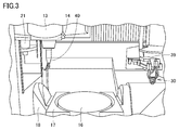
- FIG. 3 is a view showing a state in which the tool holder 40 is attached to the spindle 14.
- the operating system 11 performs control to open the door 19 and then mounts the tool holder 40 on the spindle 14 by an automatic tool changer.
- the tool holder 40 is replaced while the additional manufacturing device 30 is stored in the holder 39.
- FIG. 4 is a diagram for explaining the principle of the additional manufacturing technology by the additional manufacturing apparatus 30.
- the additional manufacturing device 30 moves in a predetermined direction (the direction of the arrow), and the laser light 391, the metal powder 392, and the shield from the tip end portion 311 of the discharge unit 310. And the carrier gas 393.
- a melting point 394 is formed on the surface of the work 399, and as a result, the metal powder 392 is deposited.
- a buildup layer 396 is formed on the work 399.
- a surfacing material 395 is placed on the surfacing layer 396.
- a processable metal layer is formed on the work 399. Note that an electron beam may be used instead of the laser light 391.
- processing performed by the machine tool 1 will be described by giving a specific example.
- processing for manufacturing a composite material by implementing cutting and additional manufacturing techniques will be described.
- a method of manufacturing a tubular body will be described as an example.
- shape of the composite material manufactured is not limited to a tubular shape.
- material of the composite material manufactured is not limited to the example mentioned later.
- FIG. 5 is a view for explaining a process for obtaining a base material by cutting the work 100.
- machine tool 1 starts cutting using tool holder 40 in order to form grooves 111 of a predetermined pattern on the surface of cylindrical workpiece 100 fixed to fixing jig 50.
- the material of the work 100 can be, for example, steel.
- the formation of the groove is performed together with the rotation of the rotary table 16 and the movement of the tool holder 40 (for example, movement in the Y-axis direction). Further, the rotational speed of the rotary table 16, the moving speed of the tool holder 40, the rotational speed of the end mill of the tool holder 40, and the like are determined based on an instruction from the operating system 11.
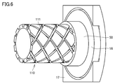
- FIG. 6 is a view showing the appearance of the base material 110 manufactured by cutting the work 100.
- base material 110 has grooves 111 of a predetermined pattern on the surface.
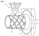
- FIG. 7 is a view showing a state in which the additional manufacturing technique is performed on the base material 110.
- machine tool 1 performs addition (3D printing) of a metal different from steel to groove 111 using additional manufacturing device 30.
- the machine tool 1 discharges a powder such as, for example, a copper alloy, an aluminum alloy, or a nickel-based superalloy from the tip end portion 311 of the additive manufacturing device 30 to form the metal layer 120 on the surface of the groove 111.
- a powder such as, for example, a copper alloy, an aluminum alloy, or a nickel-based superalloy from the tip end portion 311 of the additive manufacturing device 30 to form the metal layer 120 on the surface of the groove 111.
- the machine tool 1 forms the metal layer 120 having such a thickness that the groove portion 111 is embedded by an additional manufacturing technique. That is, the machine tool 1 fills the groove portion 111 with a metal different in material from the base material 110.
- the operating system 11 may restrict the discharge of the powder 392 from the discharge unit 310 so that the buildup is not performed twice at the intersection of the grooves in the groove 111.
- the program of the operating system 11 can be designed in advance so as to limit the discharge at the position where the intersection occurs. Just do it.
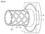
- FIG. 8 is a view showing the appearance of an intermediate 200 obtained by performing the additive manufacturing technique on the base material 110.
- intermediate 200 is a composite having base material 110 and metal layer 120.
- the metal layer 120 has the same pattern as the grooves 111 formed by cutting.
- the machine tool 1 performs surface processing on the intermediate 200. Specifically, the machine tool 1 performs surface processing on at least the surface of the metal layer 120. The machine tool 1 may also perform surface processing on the base material 110 in the same manner as the metal layer 120.
- FIG. 9 is a view showing the appearance of the intermediate 200 after the intermediate 200 is subjected to surface processing. Referring to FIG. 9, surface processing can reduce unevenness of the surface of intermediate 200 as compared to the state of FIG. 8.
- the surface processing on the intermediate 200 may not necessarily be performed.
- the intermediate 200 which is a composite material, is added on the surface of the base material 110 (first member) made of the first material (for example, steel) using directional energy deposition as the additive manufacturing method. It is manufactured by a manufacturing method comprising the step of depositing a second material of a type different from the first material (for example, a copper alloy, an aluminum alloy, or a nickel-based superalloy) using a manufacturing technique. Moreover, such a method of manufacturing a tubular body is implemented by installing the base material 110 (first member) in the processing area of the machine tool 1 that performs removal processing. Since the composite material is manufactured in the processing area in the machine tool 1, it can be processed quickly.
- a manufacturing method comprising the step of depositing a second material of a type different from the first material (for example, a copper alloy, an aluminum alloy, or a nickel-based superalloy) using a manufacturing technique.
- a method of manufacturing a tubular body is implemented by installing the base material 110 (first member) in the processing area of the machine
- the method for manufacturing a tubular body described above further includes the step of manufacturing the base material 110 by cutting the work 100 using the machine tool 1. Therefore, the manufacturing of the base material 110 and the additional manufacturing technique can be performed in the same device (specifically, the processing area of the machine tool 1).
- the second material is attached to the cut portion. Therefore, part of the work 100 can be replaced by the metal layer of the second material.
- FIG. 10 is a view showing a state in which the additional manufacturing technique is performed on the intermediate 200.
- machine tool 1 performs overlaying (3D printing) on the outer peripheral surface of intermediate body 200 using powder of steel, using additional manufacturing apparatus 30. That is, the machine tool 1 forms the metal layer 130 of steel on the outer peripheral surface of the intermediate 200.
- the formation of the metal layer 130 is performed together with the rotation of the rotary table 16 and the movement of the additional manufacturing device 30 (for example, movement in the Y-axis direction).
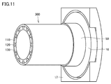
- FIG. 11 is a view showing the appearance of a finished product 300 obtained by performing the additive manufacturing technique on the surface-processed intermediate 200 (FIG. 9). Specifically, FIG. 11 shows the appearance of a finished product 300 obtained by performing surface processing on the outer peripheral surface after the application of the additional manufacturing technique.
- a finished product 300 which is a composite material is a composite material having a base material 110, a metal layer 120, and a metal layer 130 as an outer layer.
- the step of manufacturing the metal layer 130 (third member) for covering the intermediate 200 after surface processing (after removal) is performed using the additional manufacturing technology. Further equipped. According to the said structure, it becomes possible to form several metal layers 120 and 130 in which materials differ mutually with respect to the surface of the base material 110. FIG.
- Copper alloys have lower strength but higher thermal conductivity than steel.
- the presence of the metal layer 120 can enhance the thermal conductivity of the finished product 300 as compared to a tube of the same shape made of only steel.
- only the metal layer 120 is a copper alloy, it is comparable in strength as compared to a tube of the same shape made of only steel.
- the metal layer 120 is present between the base material 110 and the metal layer 130, the exposure of the metal layer 120, which is inferior in strength to the base material 110 and the metal layer 130, to the outside of the finished product 300 It will not be removed. For this reason, even when an external force acts on the surface of the finished product 300, it is less likely to be scratched as compared with the case where the metal layer of the copper alloy is exposed. Furthermore, since the copper alloy metal layer 120 is not exposed, heat retention is excellent as compared to the case where it is exposed.
- the material of the metal layer 120 is an aluminum alloy, it has the same advantage as the case where the material of the metal layer 120 is a copper alloy.
- Nickel-based superalloys have higher strength than steel. Therefore, due to the presence of the metal layer 120, the finished product 300 can dramatically increase its strength as compared to a tube of the same shape made of only steel. Thus, in the finished product 300, the metal layer 120 can function as a reinforcing material. Furthermore, the finished product 300 can increase the vibration damping ratio (that is, the ability of the material to absorb and damp vibration energy) as compared to a tube of the same shape made only of steel.
- the difference between the strength of the finished product 300 and the strength of the tube of the same shape made only of steel is the difference between the strength of carbon fiber reinforced plastic (CFRP: carbon-fiber-reinforced plastic) and the strength of a simple plastic. It can be compared as
- CFRP carbon-fiber-reinforced plastic
- the finished product 300 can be a product of lower thermal conductivity than a tube of the same shape made only of steel.
- the finished product 300 can be manufactured cheaply as compared to a tube of the same shape made only of a nickel-based superalloy.
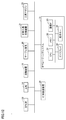
- FIG. 12 is a diagram showing an outline of the hardware configuration of the machine tool 1.
- the machine tool 1 has an operating system 11, a spindle head 13, a spindle 14, a rotating device 18, a table device 20, an automatic tool changer 21, a tool magazine 22, and additional manufacturing. And an apparatus 30.
- the operating system 11 includes a central processing unit (CPU) 91, a memory 92, a communication interface (interface) 93, a display 94, and an operation key 95.
- CPU central processing unit
- memory 92
- communication interface interface
- display 94
- operation key 95 an operation key
- the CPU 91 controls the operation of each unit of the machine tool 1 through the communication IF 93 by executing various programs stored in the memory 92.
- the display 94 displays various information in the machine tool 1 so as to be visible to the user of the machine tool 1.
- the operation key 95 receives various inputs (for example, input of start of processing) by the user.
- FIG. 13 is a flow chart showing the flow of processing for producing the finished product 300.
- machine tool 1 cuts work piece 100 to generate base material 110.
- the machine tool 1 forms the metal layer 120 on the surface of the base material 110 by attaching a material of a type different from that of the base material 110 to the base material 110 using the additive manufacturing technology. Thereby, an intermediate 200 is generated.
- step S6 the machine tool 1 cuts the surface of the metal layer 120 in the intermediate 200. That is, the machine tool 1 performs surface processing for removing a part of the metal layer 120.
- the machine tool 1 may not necessarily execute step S6 as described above.
- step S8 the machine tool 1 manufactures the metal layer 130 for covering the cut metal layer 120 using the additional manufacturing technology.
- step S10 the machine tool 1 cuts the surface of the metal layer 130. That is, the machine tool 1 performs surface processing for removing a part of the metal layer 130. Thereby, the finished product 300 is produced.
- the base material 110 may be manufactured by an additive manufacturing technique. That is, the base material 110 may be manufactured by overlaying a work (not shown).
- the additional manufacturing apparatus 30 may be configured to have two or more discharge ports, for example, so that different metal powders can be discharged for each discharge port.
- the addition manufacturing apparatus 30 is used to build up the outer peripheral surface of the intermediate body 200 using powder of the same material as that of the base material 110 (that is, steel).
- a metal layer 130 was made.
- the present invention is not limited to this, and the metal layer 130 which is the outer layer may be formed using a metal of a material different from the material of the powder used for forming the steel and the metal layer 120.
- metal layers 120 and 130 formed by the additional manufacturing technique were mentioned and demonstrated, it is not limited to this.
- the metal layers 120 and 130 may be subjected to various processes (for example, drilling) using various tools in the machine tool 1.
- FIG. 14 is a diagram for describing a configuration in which the discharge direction of metal powder when performing the additive manufacturing technique is changed for each region to be discharged.
- FIG. 14 (A) shows a state in the middle of performing deposition (3D printing) of a metal different from steel to the groove 111 similarly to FIG. 7.
- FIG. 14B shows a state in the middle of overlaying of a metal different from steel with respect to a region 112 different from the groove portion 111 in the surface (outer peripheral surface) of the base material 110.
- the machine tool 1 applies the irradiation angle of the laser beam 391 to the area 112 and the discharge angle of the metal powder 392 to the irradiation angle of the laser beam 391 to the groove 111 and the metal
- the discharge angle of the powder 392 is set to be different.
- the operating system 11 sets the base so that the irradiation angle of the laser beam 391 to the groove 111 and the discharge angle of the powder 392 become the first angle.
- the attitude of the material 110 is controlled.
- the operating system 11 also generates a second angle at which the discharge angle of the laser light 391 and the powder 392 with respect to the region 112 is different from the first angle.
- the attitude of the base material 110 is controlled to be
- the machine tool 1 it is possible to change the build-up direction (stacking direction) of the base metal for each area set in advance by the user. Therefore, the machine tool 1 can manufacture a composite material having a complicated shape, as compared with a configuration in which the buildup direction can not be changed for each area.
Landscapes
- Engineering & Computer Science (AREA)
- Mechanical Engineering (AREA)
- Physics & Mathematics (AREA)
- Optics & Photonics (AREA)
- Manufacturing & Machinery (AREA)
- Chemical & Material Sciences (AREA)
- Materials Engineering (AREA)
- Plasma & Fusion (AREA)
- Composite Materials (AREA)
- Powder Metallurgy (AREA)
- Laser Beam Processing (AREA)
Abstract
複合材は、第1の材料で構成されたベース材(110)の表面に、付加製造方式を指向性エネルギー堆積とした付加製造技術を用いて、第1の材料とは異なる種類の第2の材料を付着させる工程を備えた製造方法により製造される。当該製造方法は、除去加工を行なう工作機械の加工領域内にベース材(110)の部材を設置することにより実施される。これにより、付加製造技術によって製造された複合材であって、速やかに加工可能な状態にある複合材を得ることができる。
Description
本発明は、異なる金属を含んで構成される複合材、および当該複合材の製造方法に関する。
従来、金属による肉盛りを行なうことによって複合材を製造することが知られている。
特開平10-337618号公報(特許文献1)には、このような肉盛りがなされた複合材に対する加工を行なう加工装置が開示されている。詳しくは、特許文献1には、アルミニウム系鋳造合金製のシリンダヘッドにおけるバルブシート部に銅合金粉末を溶融肉盛して形成された肉盛り部を、加工装置によって所定の形状に加工することが開示されている。
特開平10-337618号公報(特許文献1)には、このような肉盛りがなされた複合材に対する加工を行なう加工装置が開示されている。詳しくは、特許文献1には、アルミニウム系鋳造合金製のシリンダヘッドにおけるバルブシート部に銅合金粉末を溶融肉盛して形成された肉盛り部を、加工装置によって所定の形状に加工することが開示されている。
また、特開昭61-183430号公報(特許文献2)には、複合材の製造方法の一例として、射出成型機用スクリューの製造方法が開示されている。詳しくは、特許文献2には、鋼性のシャフトの溝にタングステン炭化物粉末を含む合金原料粉末混合物を充填する工程と、当該合金原料粉末混合物が充填されたシャフトを加圧状態で高温加熱することにより合金原料粉末混合物を焼結させる工程とを含んだ射出成型機用スクリューの製造方法が開示されている。
また、従来、付加製造技術(Additive manufacturing)が知られている。付加製造技術とは、後掲する非特許文献1にも記載されているように、材料を付着することによって物体を3次元形状の数値表現から作成するプロセスを指す。付加製造技術は、多くの場合、層の上に層を積むことによって実現され、除去的な製造方法と対照的なものである。なお、このような付加製造技術の定義は、工業規格に関する民間規格制定機関であるASTMインターナショナルにおけるASTM F2792-12a(Standard Terminology for Additive Manufacturing Technologies)においてなされている。また、付加製造技術は、「3Dプリンター」とも称される。
特許庁、"平成25年度 特許出願技術動向調査報告書(概要) 3Dプリンター"、[online]、平成26年3月、[平成26年9月19日検索]、インターネット(URL:http://www.jpo.go.jp/shiryou/pdf/gidou-houkoku/25_3dprinter.pdf)
特許文献1における肉盛りは、単に、被肉盛り部材(すなわち素材)とは異なった特性を持つ材料を素材面に付加する技術にすぎず、物体を3次元形状の数値表現から作成するプロセスを有していない。それゆえ、特許文献1における肉盛りは、付加製造技術を用いたものに該当しない。
また、除去加工を行なう工作機械としての特許文献1の加工装置は、肉盛りがなされた複合材に対する加工を行なうための装置であって、肉盛りを行なう機能を有していない。それゆえ、肉盛りは、加工装置以外の装置で実行される。したがって、肉盛りがなされた複合材に対して加工を行なう場合には、ユーザは、当該複合材を移動し、当該複合材を加工装置内の所定位置に設置しなければならない。
特許文献2の製造方法は、付加製造技術ではなく焼結によって複合材を得る構成であるため、以下のデメリットを有する。すなわち、溝の角部(隅部)においては合金原料粉末混合物の充填が不十分になりやすく、接合箇所に気泡が生じる可能性が高い。そのため、接合箇所における接合強度が低下したり、熱伝導性が低下したりするといった問題がある。
本願発明は、上記の問題点に鑑みなされたものであって、その目的は、付加製造技術によって製造された複合材であって、速やかに加工可能な状態にある複合材を得ることにある。
本発明に係る複合材は、複合材は、第1の材料で構成された第1の部材の表面に、付加製造方式を指向性エネルギー堆積とした付加製造技術を用いて、第1の材料とは異なる種類の第2の材料を付着させる工程を備えた製造方法により製造される。製造方法は、除去加工を行なう工作機械の加工領域内に第1の部材を設置することにより実施される。
好ましくは、製造方法は、付着された第2の材料で構成された第2の部材の一部を除去する工程をさらに備える。
好ましくは、製造方法は、除去後の第2の部材を覆うための第3の部材を、付加製造技術を用いて製造する工程をさらに備える。
好ましくは、製造方法は、工作機械を用いてワークを切削することにより第1の部材を製造する工程をさらに備える。
好ましくは、第2の材料を付着させる工程では、切削された箇所に対して第2の材料を付着させる。
好ましくは、製造方法は、付加製造技術により第1の部材を製造する工程をさらに備える。
好ましくは、指向性エネルギー堆積は、レーザまたは電子ビームのいずれかを利用するものである。工作機械は、加工領域内に設置された第1の部材の姿勢を変更可能である。製造方法は、第1の部材の表面における第1の領域においては、第1の領域に対するレーザまたは電子ビームの照射角度が第1の角度となるように、第1の部材の姿勢を制御する。製造方法は、第1の部材の表面における第2の領域においては、第2の領域に対するレーザまたは電子ビームの照射角度が第2の角度となるように、第1の部材の姿勢を制御する。
好ましくは、第2の材料は第1の材料よりも熱伝導性が高い。
好ましくは、第2の材料は第1の材料よりも強度が強い。
好ましくは、第2の材料は第1の材料よりも強度が強い。
本発明の他の局面に従うと、複合材の製造方法は、第1の材料で構成された部材の表面に、付加製造方式を指向性エネルギー堆積とした付加製造技術を用いて、第1の材料とは異なる種類の第2の材料を付着させる工程を備える。工程は、除去加工を行なう工作機械の加工領域内に第1の部材を設置することにより実施される。
本発明によれば、付加製造技術によって製造された複合材であって、速やかに加工可能な状態にある複合材を得ることが可能となる。
以下、図面を参照しつつ、本発明の実施の形態に係る複合材および複合材を製造するための工作機械について説明する。以下の説明では、同一の部品には同一の符号を付してある。それらの名称および機能も同じである。したがって、それらについての詳細な説明は繰り返さない。
また、以下では、上記工作機械の一例として、付加製造技術(すなわち3Dプリンター)の機能を備えた5軸加工機を例に挙げて説明する。しかしながら、工作機械は、5軸加工機に限定されるものではない。工作機械は、付加製造技術の機能を備えた除去加工機(たとえば、4軸加工機)であればよい。さらに、以下では、付加製造技術における付加製造方式として、指向性エネルギー堆積を利用するものとする。
<A.工作機械の概要>
図1は、複合材を製造するための工作機械1の外観および内部構造を説明するための概要図である。図1を参照して、工作機械1は、オペレーティングシステム11と、スプラッシュガード12と、主軸頭13と、主軸14と、回転装置18と、扉19と、テーブル装置20とを備える。
図1は、複合材を製造するための工作機械1の外観および内部構造を説明するための概要図である。図1を参照して、工作機械1は、オペレーティングシステム11と、スプラッシュガード12と、主軸頭13と、主軸14と、回転装置18と、扉19と、テーブル装置20とを備える。
テーブル装置20は、回転テーブル16と、回転テーブル16を回転可能に支持する台座17とを有する。テーブル装置20は、回転装置18に取り付けられている。詳しくは、台座17が回転装置18の中央部に固定されている。
オペレーティングシステム11は、従来の操作盤の役割を果たす数値制御装置である。オペレーティングシステム11は、ユーザが設計したプログラム等を実行することにより、工作機械1の全体の動作を制御する。たとえば、オペレーティングシステム11は、主軸頭13、主軸14、回転装置18、扉19、テーブル装置20、後述する付加製造装置30の動作を制御する。なお、オペレーティングシステム11は、周知のシステムであるので、ここでは詳しくは説明しない。
主軸頭13は、図示しないクロスレールに取り付けられている。主軸頭13は、矢印901に示す軸方向(X軸方向)および矢印902に示す軸方向(Y軸方向)にスライド移動可能に設けられている。主軸頭13には、主軸14が取り付けられている。
主軸14は、矢印903に示す軸方向(Z軸方向)にスライド移動可能に設けられている。主軸14は、先端に、工具が取り付けられた工具ホルダを装着するための機構を有する。
工具ホルダの例としては、付加製造技術を実行するための付加製造装置30(図2)、工具マガジン(図示せず)に格納されている工具ホルダ(たとえば、エンドミルを備えた工具ホルダ40(図3))が挙げられる。なお、付加製造装置30以外の工具ホルダは、自動工具交換装置21(図3)によって、主軸14に取り付けられる。
工具マガジンは、扉19に対して加工領域とは反対側(すなわち図1における扉19の奥側)に配置されている。なお、「加工領域」とは、スプラッシュガード12および扉19によって仕切られる空間(工作機械1の内部側の空間)であって、主軸頭13、主軸14、回転装置18、テーブル装置20、付加製造装置30、ワーク等が移動可能に配置される空間を指す。
主軸頭13および主軸14の各々には、スライド移動を可能とするための送り機構や案内機構、サーボモータなどが適宜、設けられている。工作機械1においては、主軸頭13および主軸14の各々のスライド移動が組み合わさることにより、工具ホルダに取り付けられた工具の位置をXYZ空間において自在に変化させることができる。
回転装置18は、X軸方向に延びる中心軸を中心に、モータ駆動により回転可能に設けられている。回転装置18の回転とともに、テーブル装置20が当該中心軸を中心にして、時計および半時計方向(矢印904の方向)に回転する。
テーブル装置20の回転テーブル16は、デフォルト状態である図1の状態においては、鉛直(Z軸)方向に延びる中心軸を中心に、モータ駆動により回転可能に設けられている。なお、回転テーブル16は、回転装置18によって矢印904の方向に回転するため、回転テーブル16の回転の中心軸はYZ平面に平行な状態を保ちながら変化する。
回転テーブル16上には、チャックや各種の治具を用いて、ワークが保持される。固定工具を用いた切削加工時、回転テーブル16の回転とともにワークが当該中心軸を中心にして時計および半時計方向(矢印905の方向)に回転する。
以上のような構成により、工作機械1は、加工領域内に設置されたワーク等の部材の姿勢を変更することが可能となる。
図2は、主軸14に付加製造装置30が取り付けられた状態を表した図である。図2を参照して、付加製造装置30は、吐出部310と、取付部320と、ホース部330とを備える。
詳細については後述するが、吐出部310の先端部311から金属の粉体等が吐出される。取付部320は、付加製造装置30を主軸14に固定させるための部材である。ホース部330は、粉体等の供給路である。ホース部330は、粉体等が格納された装置(図示せず)から、取付部320を介して粉体等を吐出部310に供給するために設けられている。
工作機械1は、付加製造装置30を使用しない場合には、付加製造装置30を付加製造装置用のホルダ39に格納する。なお、ホルダ39は、XY平面に平行な状態を保ちながら回転可能に構成されている。つまり、ホルダ39は、Z軸に平行な軸を中心に回転する。
図3は、主軸14に工具ホルダ40が取り付けられた状態を表した図である。図3を参照して、オペレーティングシステム11は、扉19を開く制御を行ない、その後、自動工具交換装置によって工具ホルダ40を主軸14に取り付けさせる。なお、工具ホルダ40の交換は、付加製造装置30をホルダ39に格納した状態で行なわれる。
図4は、付加製造装置30による付加製造技術の原理を説明するための図である。図4を参照して、付加製造装置30は、予め定められた方向(矢印の方向)に移動しつつ、吐出部310の先端部311から、レーザ光391と、金属の粉体392と、シールドおよびキャリア用のガス393とを吐出する。これにより、ワーク399の表面に溶融点394が形成され、その結果、金属の粉体392が溶着する。
具体的には、ワーク399の上に肉盛層396が形成される。肉盛層396の上には肉盛素材395が盛られる。肉盛素材395が冷却されると、ワーク399の上に加工可能な金属層が形成された状態となる。なお、レーザ光391の代わりに電子ビームを用いてもよい。
<B.処理例>
以下、工作機械1によって行われる加工処理について具体例を挙げて説明する。詳しくは、工作機械1によって行われる加工処理の一例として、切削加工および付加製造技術を実施することにより複合材を製造する処理を説明する。特に、以下では、管体を製造する製造方法を例に挙げて説明する。なお、製造される複合材の形状は、管状に限定されない。また、製造される複合材の材質は、後述する例に限定されるものではない。
以下、工作機械1によって行われる加工処理について具体例を挙げて説明する。詳しくは、工作機械1によって行われる加工処理の一例として、切削加工および付加製造技術を実施することにより複合材を製造する処理を説明する。特に、以下では、管体を製造する製造方法を例に挙げて説明する。なお、製造される複合材の形状は、管状に限定されない。また、製造される複合材の材質は、後述する例に限定されるものではない。
(b1.ベース材の生成)
図5は、ワーク100に対して切削加工を行なうことによりベース材を得るための処理を説明するための図である。図5を参照して、工作機械1は、固定治具50に固定された円筒形状のワーク100の表面に所定のパターンの溝部111を形成するために、工具ホルダ40を用いて切削を開始する。ワーク100の材質(材料)としては、一例として、鋼鉄とすることができる。
図5は、ワーク100に対して切削加工を行なうことによりベース材を得るための処理を説明するための図である。図5を参照して、工作機械1は、固定治具50に固定された円筒形状のワーク100の表面に所定のパターンの溝部111を形成するために、工具ホルダ40を用いて切削を開始する。ワーク100の材質(材料)としては、一例として、鋼鉄とすることができる。
なお、溝の形成は、回転テーブル16の回転および工具ホルダ40の移動(たとえば、Y軸方向への移動)を伴って行われる。また、回転テーブル16の回転速度、工具ホルダ40の移動速度、工具ホルダ40のエンドミルの回転速度等は、オペレーティングシステム11からの指示に基づき決定される。
図6は、ワーク100に対する切削加工により製造されたベース材110の外観を表した図である。図6を参照して、ベース材110は、表面に所定パターンの溝部111を有する。
(b2.1回目の3次元プリンティング処理、および表面加工処理)
図7は、ベース材110に対して付加製造技術を実施している状態を表した図である。図7を参照して、工作機械1は、付加製造装置30を用いて、溝部111に対して鋼鉄とは異なる金属の肉盛(3Dプリンティング)を行なう。
図7は、ベース材110に対して付加製造技術を実施している状態を表した図である。図7を参照して、工作機械1は、付加製造装置30を用いて、溝部111に対して鋼鉄とは異なる金属の肉盛(3Dプリンティング)を行なう。
具体的には、工作機械1は、たとえば銅合金、アルミニウム合金、またはニッケルベースの超合金等の粉体を付加製造装置30の先端部311から吐出させることにより、溝部111の表面に金属層120を形成する。より詳しくは、工作機械1は、付加製造技術によって、溝部111が埋まる程度の厚みを有する金属層120を形成する。つまり、工作機械1は、溝部111をベース材110とは異なる材質の金属で充填する。
なお、溝部111における溝の交差点においては、2回にわたり肉盛りが行われないように、オペレーティングシステム11は、吐出部310からの粉体392の吐出を制限してもよい。ユーザが設計したプログラムに基づき交差が生じる位置(ベース材110の表面における位置)を判断することにより、当該交差が生じる位置において吐出を制限するように、オペレーティングシステム11のプログラムを予め設計しておけばよい。
図8は、ベース材110に対して付加製造技術を実施することにより得られた中間体200の外観を表した図である。図8を参照して、中間体200は、ベース材110と、金属層120とを有する複合材となる。金属層120は、切削により形成された溝部111と同じパターンを有している。
次に、付加製造技術により付着(溶着)された第2の材料で構成された金属層120(第2の部材)の一部を除去する工程について説明する。図8の中間体200が得られた後、工作機械1は、中間体200に対して表面加工を施す。詳しくは、工作機械1は、少なくとも金属層120の表面に対して表面加工を施す。なお、工作機械1は、ベース材110に対しても、金属層120と同様に表面加工を施してもよい。
図9は、中間体200に対して表面加工を施した後の中間体200の外観を表した図である。図9を参照して、表面加工により、図8の状態に比べて、中間体200の表面の凹凸が低減させることができる。
なお、後述するように、中間体200の表面に対してさらに付加製造技術を実施する場合(図10)には、中間体200に対する表面加工を必ずしも行なわなくてもよい。
以上のように、複合材である中間体200は、第1の材料(たとえば鋼鉄)で構成されたベース材110(第1の部材)の表面に、付加製造方式を指向性エネルギー堆積とした付加製造技術を用いて、第1の材料とは異なる種類の第2の材料(たとえば、銅合金、アルミニウム合金、またはニッケルベースの超合金)を付着させる工程を備えた製造方法により製造される。また、このような管体の製造方法は、除去加工を行なう工作機械1の加工領域内にベース材110(第1の部材)を設置することにより実施される。当該複合材は、工作機械1内の加工領域内で製造されるため、速やかに加工可能となる。
また、上記の管体の製造方法は、工作機械1を用いてワーク100を切削することによりベース材110を製造する工程をさらに備える。したがって、ベース材110の製造と、付加製造技術とを、同じ装置内(詳しくは、工作機械1の加工領域)で実施することができる。
また、上記第2の材料をベース材110に付着させる工程では、切削された箇所に対して第2の材料を付着させる。したがって、ワーク100の一部を、上記第2の材料による金属層で置き換えることが可能となる。
(b3.2回目の3次元プリンティング処理)
図10は、中間体200に対して付加製造技術を実施している状態を表した図である。図10を参照して、工作機械1は、付加製造装置30を用いて、中間体200の外周面に対して、鋼鉄の粉体を用いて肉盛(3Dプリンティング)を行なう。つまり、工作機械1は、中間体200の外周面に鋼鉄の金属層130を形成する。なお、金属層130の形成は、回転テーブル16の回転および付加製造装置30の移動(たとえば、Y軸方向への移動)を伴って行われる。
図10は、中間体200に対して付加製造技術を実施している状態を表した図である。図10を参照して、工作機械1は、付加製造装置30を用いて、中間体200の外周面に対して、鋼鉄の粉体を用いて肉盛(3Dプリンティング)を行なう。つまり、工作機械1は、中間体200の外周面に鋼鉄の金属層130を形成する。なお、金属層130の形成は、回転テーブル16の回転および付加製造装置30の移動(たとえば、Y軸方向への移動)を伴って行われる。
図11は、表面加工後の中間体200(図9)に対して付加製造技術を実施することにより得られた完成品300の外観を表した図である。詳しくは、図11は、当該付加製造技術の実施後に外周面の表面加工を施すことにより得られた完成品300の外観を表している。図11を参照して、複合材である完成品300は、ベース材110と、金属層120と、アウターレイヤとしての金属層130とを有する複合材となる。
以上のように、上記の管体の製造方法は、表面加工後(除去後)の中間体200を覆うための金属層130(第3の部材)を、付加製造技術を用いて製造する工程をさらに備える。当該構成によれば、ベース材110の表面に対して、互いに材質が異なる複数の金属層120,130を形成することが可能となる。
(b4.得られた完成品の利点)
(1)ベース材110および金属層130の材質が鋼鉄であり、金属層120の材質が銅合金である場合の利点について説明する。
(1)ベース材110および金属層130の材質が鋼鉄であり、金属層120の材質が銅合金である場合の利点について説明する。
銅合金は、鋼鉄に比べて、強度は劣るが、熱伝導率が高い。したがって、金属層120の存在により、完成品300は、鋼鉄のみで構成された同形状の管体に比べて、熱伝導性を高めることができる。また、金属層120のみが銅合金であるため、鋼鉄のみで構成された同形状の管体に比べて、強度の面でも遜色がない。
特に、金属層120がベース材110と金属層130との間に存在するため、ベース材110および金属層130に比べて強度に劣る金属層120の外部への露出が完成品300の両端部を除きなくなる。このため、完成品300の表面に何らかの外力が働いた場合であっても、銅合金の金属層が露出している場合に比べて、傷がつきにくい。さらに、銅合金の金属層120が露出していないので、露出している場合に比べて、熱の保温性に優れる。
なお、金属層120の材質がアルミニウム合金である場合も、金属層120の材質が銅合金である場合と同様な利点を有する。
(2)次に、ベース材110および金属層130の材質が鋼鉄であり、金属層120の材質がニッケルベースの超合金である場合の利点について説明する。
ニッケルベースの超合金は、鋼鉄に比べて、強度が高い。したがって、金属層120の存在により、完成品300は、鋼鉄のみで構成された同形状の管体に比べて、強度を飛躍的に高めることができる。このように、完成品300において、金属層120を補強材として機能させることができる。さらには、完成品300は、鋼鉄のみで構成された同形状の管体に比べて、振動減衰比(つまり、材料が振動エネルギーを吸収して減衰する能力)を高めることが可能となる。なお、完成品300の強度と鋼鉄のみで構成された同形状の管体の強度との差は、炭素繊維強化プラスチック(CFRP:carbon-fiber-reinforced plastic)の強度と単なるプラスチックの強度との差として例えることができる。
また、ニッケルベースの超合金は、鋼鉄に比べて、熱伝導率が低い。したがって、完成品300に低い熱伝導率が要求されている場合には、完成品300を、鋼鉄のみで構成された同形状の管体よりも低い熱伝導性の製品とすることができる。
また、ニッケルベースの超合金は、鋼鉄に比べて値段が高い。したがって、完成品300は、ニッケルベースの超合金のみで構成された同形状の管体に比べて、安く製造することができる。
<C.ハードウェア構成>
図12は、工作機械1のハードウェア構成の概要を表した図である。図12を参照して、工作機械1は、オペレーティングシステム11と、主軸頭13と、主軸14と、回転装置18と、テーブル装置20と、自動工具交換装置21と、工具マガジン22と、付加製造装置30とを備える。
図12は、工作機械1のハードウェア構成の概要を表した図である。図12を参照して、工作機械1は、オペレーティングシステム11と、主軸頭13と、主軸14と、回転装置18と、テーブル装置20と、自動工具交換装置21と、工具マガジン22と、付加製造装置30とを備える。
オペレーティングシステム11は、CPU(Central Processing Unit)91と、メモリ92と、通信IF(InterFace)93と、ディスプレイ94と、操作キー95とを有する。
CPU91は、メモリ92に格納された各種プログラムを実行することにより、通信IF93を介して、工作機械1の各部の動作を制御する。ディスプレイ94は、工作機械1における各種の情報を工作機械1のユーザに視認可能に表示する。操作キー95は、ユーザによる様々な入力(たとえば、加工開始の入力)を受け付ける。
オペレーティングシステム11がユーザからの指示に応じた処理(ユーザが作成したプログラムに基づく処理)を実行することにより、たとえば、図5から図11に基づいて説明したように、ワーク100から複合材の完成品300が製造される。
<D.制御構造>
図13は、完成品300を製造するための処理の流れを表したフローチャートである。図13を参照して、ステップS2において、工作機械1は、ワーク100を切削して、ベース材110を生成する。ステップS4において、工作機械1は、ベース材110の材料とは異なる種類の材料を、付加製造技術を用いてベース材110に付着させることにより、ベース材110の表面に金属層120を形成する。これにより、中間体200が生成される。
図13は、完成品300を製造するための処理の流れを表したフローチャートである。図13を参照して、ステップS2において、工作機械1は、ワーク100を切削して、ベース材110を生成する。ステップS4において、工作機械1は、ベース材110の材料とは異なる種類の材料を、付加製造技術を用いてベース材110に付着させることにより、ベース材110の表面に金属層120を形成する。これにより、中間体200が生成される。
ステップS6において、工作機械1は、中間体200における金属層120の表面を切削する。つまり、工作機械1は、金属層120の一部を除去するための表面加工を行なう。なお、工作機械1は、上述したように、ステップS6を必ずしも実行しなくてもよい。
ステップS8において、工作機械1は、切削された金属層120を覆うための金属層130を、付加製造技術を用いて製造する。ステップS10において、工作機械1は、金属層130の表面を切削する。つまり、工作機械1は、金属層130の一部を除去するための表面加工を行なう。これにより、完成品300が生成される。
<E.変形例>
(1)上記においては、ワーク100を工具で切削することによりベース材を生成する方法を説明したが、これに限定されるものではない。たとえば、ベース材110を、付加製造技術により製造してもよい。つまり、ワーク(図示せず)に対して肉盛りを行なうことにより、ベース材110を製造してもよい。
(1)上記においては、ワーク100を工具で切削することによりベース材を生成する方法を説明したが、これに限定されるものではない。たとえば、ベース材110を、付加製造技術により製造してもよい。つまり、ワーク(図示せず)に対して肉盛りを行なうことにより、ベース材110を製造してもよい。
(2)上記においては、吐出部310における粉体392の吐出口が1つである構成(図4)を例に挙げて説明したが、これに限定されるものではない。2つ以上の吐出口を有し、たとえば吐出口毎に異なる金属の粉体を吐出可能なように、付加製造装置30を構成してもよい。
(3)上記においては、付加製造装置30を用いて、中間体200の外周面に対して、ベース材110と同じ材質(つまり、鋼鉄)の粉体を用いて肉盛を行なうことにより、鋼鉄製の金属層130を作成した。しかしながら、これに限定されず、鋼鉄および金属層120の形成に用いた粉体の材質とは異なる材質の金属を用いて、アウター層である金属層130を形成してもよい。
(4)上記では、付加製造技術により形成された金属層120,130に対して、表面加工を行なう例をあげて説明したが、これに限定されるものではない。工作機械1における様々な工具を用いて、金属層120,130に様々な加工(たとえば、穴開け加工)を施してもよい。
(5)複合材の製造方法を以下のようにしてもよい。図14は、付加製造技術を実行する際における金属の粉体の吐出の向きを、吐出対象となる領域毎に変更する構成を説明するための図である。
図14(A)は、図7と同様に、溝部111に対して鋼鉄とは異なる金属の肉盛(3Dプリンティング)をしている途中の状態を表している。図14(B)は、ベース材110における表面(外周面)のうち、溝部111とは異なる領域112に対して、鋼鉄とは異なる金属の肉盛をしている途中の状態を表している。
図14(A),(B)を参照して、工作機械1は、領域112に対するレーザ光391の照射角度および金属の粉体392の吐出角度を、溝部111に対するレーザ光391の照射角度および金属の粉体392の吐出角度とは異なるように設定する。
つまり、オペレーティングシステム11は、ベース材110の表面における溝部(第1の領域)においては、溝部111に対するレーザ光391の照射角度および粉体392の吐出角度が第1の角度となるように、ベース材110の姿勢を制御する。また、オペレーティングシステム11は、ベース材110の表面における領域112(第2の領域)においては、領域112に対するレーザ光391および粉体392の吐出角度が第1の角度とは異なる第2の角度となるように、ベース材110の姿勢を制御する。
このように、工作機械1によれば、ユーザが予め設定した領域毎に、下地の金属に対する肉盛り方向(積み上げる方向)を変更することができる。それゆえ、領域毎に肉盛り方向を変更できない構成に比べて、工作機械1は複雑な形状の複合材を製造することが可能となる。
今回開示された実施の形態は例示であって、上記内容のみに制限されるものではない。本発明の範囲は請求の範囲によって示され、請求の範囲と均等の意味および範囲内でのすべての変更が含まれることが意図される。
1 工作機械、11 オペレーティングシステム、12 スプラッシュガード、13 主軸頭、14 主軸、16 回転テーブル、17 台座、18 回転装置、19 扉、20 テーブル装置、21 自動工具交換装置、22 工具マガジン、30 付加製造装置、39 ホルダ、40 工具ホルダ、50 固定治具、91 CPU、92 メモリ、100,399 ワーク、110 ベース材、111 溝部、112 領域、120,130 金属層、200 中間体、300 完成品、310 吐出部、311 先端部、320 取付部、330 ホース部、391 レーザ光、392 粉体、393 ガス、395 肉盛素材、396 肉盛層。
Claims (10)
- 複合材であって、
前記複合材は、第1の材料で構成された第1の部材の表面に、付加製造方式を指向性エネルギー堆積とした付加製造技術を用いて、前記第1の材料とは異なる種類の第2の材料を付着させる工程を備えた製造方法により製造され、
前記製造方法は、除去加工を行なう工作機械の加工領域内に前記第1の部材を設置することにより実施される、複合材。 - 前記製造方法は、前記付着された前記第2の材料で構成された第2の部材の一部を除去する工程をさらに備える、請求項1に記載の複合材。
- 前記製造方法は、前記除去後の第2の部材を覆うための第3の部材を、前記付加製造技術を用いて製造する工程をさらに備える、請求項2に記載の複合材。
- 前記製造方法は、前記工作機械を用いてワークを切削することにより前記第1の部材を製造する工程をさらに備える、請求項1から3のいずれか1項に記載の複合材。
- 前記第2の材料を付着させる工程では、前記切削された箇所に対して前記第2の材料を付着させる、請求項4に記載の複合材。
- 前記製造方法は、前記付加製造技術により前記第1の部材を製造する工程をさらに備える、請求項1から3のいずれか1項に記載の複合材。
- 前記指向性エネルギー堆積は、レーザまたは電子ビームのいずれかを利用するものであり、
前記工作機械は、前記加工領域内に設置された前記第1の部材の姿勢を変更可能であり、
前記製造方法は、
前記第1の部材の表面における第1の領域においては、前記第1の領域に対する前記レーザまたは前記電子ビームの照射角度が第1の角度となるように、前記第1の部材の姿勢を制御し、
前記第1の部材の表面における第2の領域においては、前記第2の領域に対する前記レーザまたは前記電子ビームの照射角度が第2の角度となるように、前記第1の部材の姿勢を制御する、請求項1から5のいずれか1項に記載の複合材。 - 前記第2の材料は前記第1の材料よりも熱伝導性が高い、請求項1から7のいずれか1項に記載の複合材。
- 前記第2の材料は前記第1の材料よりも強度が強い、請求項1から7のいずれか1項に記載の複合材。
- 複合材の製造方法であって、
第1の材料で構成された部材の表面に、付加製造方式を指向性エネルギー堆積とした付加製造技術を用いて、前記第1の材料とは異なる種類の第2の材料を付着させる工程を備え、
前記工程は、除去加工を行なう工作機械の加工領域内に前記第1の部材を設置することにより実施される、複合材の製造方法。
Priority Applications (3)
| Application Number | Priority Date | Filing Date | Title |
|---|---|---|---|
| CN201580045228.5A CN106794561B (zh) | 2014-10-21 | 2015-07-09 | 复合构件和复合构件的制造方法 |
| US15/315,566 US11534857B2 (en) | 2014-10-21 | 2015-07-09 | Composite member and method for manufacturing composite member |
| EP15853007.1A EP3210716B1 (en) | 2014-10-21 | 2015-07-09 | Method for manufacturing a composite member |
Applications Claiming Priority (2)
| Application Number | Priority Date | Filing Date | Title |
|---|---|---|---|
| JP2014-214685 | 2014-10-21 | ||
| JP2014214685A JP5878604B1 (ja) | 2014-10-21 | 2014-10-21 | 複合材の製造方法 |
Publications (1)
| Publication Number | Publication Date |
|---|---|
| WO2016063584A1 true WO2016063584A1 (ja) | 2016-04-28 |
Family
ID=55440599
Family Applications (1)
| Application Number | Title | Priority Date | Filing Date |
|---|---|---|---|
| PCT/JP2015/069795 Ceased WO2016063584A1 (ja) | 2014-10-21 | 2015-07-09 | 複合材、および複合材の製造方法 |
Country Status (5)
| Country | Link |
|---|---|
| US (1) | US11534857B2 (ja) |
| EP (1) | EP3210716B1 (ja) |
| JP (1) | JP5878604B1 (ja) |
| CN (1) | CN106794561B (ja) |
| WO (1) | WO2016063584A1 (ja) |
Cited By (2)
| Publication number | Priority date | Publication date | Assignee | Title |
|---|---|---|---|---|
| WO2018039720A1 (en) | 2016-08-30 | 2018-03-08 | Weir Group Ip Limited | Forming a rotary part |
| JP2021042453A (ja) * | 2019-09-13 | 2021-03-18 | 株式会社東芝 | コーティング方法及びコーティング構造 |
Families Citing this family (36)
| Publication number | Priority date | Publication date | Assignee | Title |
|---|---|---|---|---|
| TWI535554B (zh) * | 2014-01-06 | 2016-06-01 | 財團法人工業技術研究院 | 立體成型物以及立體成型物的製造設備與製造方法 |
| US20170129180A1 (en) * | 2014-06-09 | 2017-05-11 | Hybrid Manufacturing Technologies Limited | Material processing methods and related apparatus |
| JP5937713B1 (ja) * | 2015-03-20 | 2016-06-22 | Dmg森精機株式会社 | 加工機械 |
| US11465357B2 (en) * | 2015-03-24 | 2022-10-11 | The Johns Hopkins University | Systems and methods for conformal additive manufacturing |
| US20180071819A1 (en) | 2016-09-15 | 2018-03-15 | NanoCore Technologies, Inc. | System and method for additive metal manufacturing |
| WO2018054902A1 (en) * | 2016-09-20 | 2018-03-29 | Autotech Engineering Aie | Reinforcing structural components |
| US11219976B2 (en) * | 2016-09-29 | 2022-01-11 | Gkn Aerospace Newington Llc | Manufacturing method for cylindrical parts |
| JP6388238B2 (ja) * | 2016-11-22 | 2018-09-12 | フドー株式会社 | 繊維強化プラスチック製品の製造方法 |
| CN108340161A (zh) * | 2017-01-24 | 2018-07-31 | 昆山快成三维科技有限公司 | 一种面向金属丝熔融沉积成型与钻铣复合机床的3d打印喷头支撑装置 |
| WO2018154719A1 (ja) * | 2017-02-24 | 2018-08-30 | 三菱重工コンプレッサ株式会社 | 積層造形方法及び積層造形装置 |
| JP6751040B2 (ja) * | 2017-03-13 | 2020-09-02 | 株式会社神戸製鋼所 | 積層造形物の製造方法、製造システム、及び製造プログラム |
| US11123819B2 (en) * | 2017-09-25 | 2021-09-21 | Hamilton Sundstrand Corporation | Additive manufacturing method |
| US11229953B2 (en) | 2017-11-29 | 2022-01-25 | Lincoln Global, Inc. | Methods and systems for additive manufacturing |
| CN108115930A (zh) * | 2018-01-16 | 2018-06-05 | 宁夏共享机床辅机有限公司 | 一种基于fdm的3d打印机防护罩 |
| CN108311703B (zh) * | 2018-02-01 | 2023-02-28 | 深圳市铭利达精密技术股份有限公司 | 新能源汽车高性能轻质精密结构件成形方法 |
| US10520923B2 (en) | 2018-05-22 | 2019-12-31 | Mantle Inc. | Method and system for automated toolpath generation |
| JP7084224B2 (ja) | 2018-06-20 | 2022-06-14 | コマツNtc株式会社 | 3次元造形装置および3次元造形方法 |
| US11426818B2 (en) | 2018-08-10 | 2022-08-30 | The Research Foundation for the State University | Additive manufacturing processes and additively manufactured products |
| JP6511577B1 (ja) | 2018-08-21 | 2019-05-15 | 独立行政法人国立高等専門学校機構 | 成形装置および成形方法 |
| EP3946780A4 (en) * | 2019-04-01 | 2022-12-28 | Stinger Advanced Manufacturing Corporation | SYSTEMS AND PROCESSES FOR THE NON-CONTINUOUS DEPOSITION OF A COMPONENT |
| US20220214121A1 (en) * | 2019-04-04 | 2022-07-07 | Titomic Limited | Multi-material device for heat transfer and a method of manufacture |
| JP6948431B2 (ja) * | 2019-04-09 | 2021-10-13 | 株式会社ExtraBold | 工作機械装置およびその制御方法 |
| EP4070937B1 (en) | 2019-12-03 | 2024-07-17 | Mitsubishi Gas Chemical Company, Inc. | Method for producing fiber-reinforced resin article |
| CN111097908A (zh) * | 2020-01-02 | 2020-05-05 | 北京机科国创轻量化科学研究院有限公司 | 一种注塑机螺杆及其制造方法 |
| WO2021171371A1 (ja) * | 2020-02-25 | 2021-09-02 | 株式会社ニコン | 加工システム |
| WO2021248057A1 (en) * | 2020-06-05 | 2021-12-09 | Dc Precision Ceramics, Llc | Manufacturing systems and methods for three-dimensional printing |
| JP6892542B1 (ja) * | 2020-08-19 | 2021-06-23 | 株式会社神戸製鋼所 | 造形物の製造方法及び造形物 |
| CN112192020B (zh) * | 2020-09-28 | 2022-09-09 | 哈尔滨理工大学 | 一种加工球头铣刀跨尺度微特征的夹具 |
| CN112024884A (zh) * | 2020-10-10 | 2020-12-04 | 浙江意动科技股份有限公司 | 一种金属铺粉激光增材制造slm工艺用3d打印设备 |
| DE102021106305A1 (de) * | 2021-03-16 | 2022-09-22 | Karlsruher Institut für Technologie (Körperschaft des öffentlichen Rechts) | Verfahren zur Herstellung von Rohren mit topographischen Innenstrukturen |
| CN113664222B (zh) * | 2021-08-23 | 2024-03-26 | 华南理工大学 | 一种用于定向能量沉积设备的复合激光装置与方法 |
| CN121152720A (zh) | 2023-04-26 | 2025-12-16 | 三菱瓦斯化学株式会社 | 纤维增强塑料制品的制造方法 |
| US20240425963A1 (en) * | 2023-06-23 | 2024-12-26 | Additive Technologies LLC d/b/a ADDITEC | Bimetallic composite parts and methods thereof |
| IT202300014919A1 (it) * | 2023-07-17 | 2025-01-17 | Ge Avio Srl | Dispositivi conformi per deposizione di energia diretta e gruppi tavola di creazione comprendenti gli stessi. |
| US20250178093A1 (en) * | 2023-11-30 | 2025-06-05 | The Boeing Company | Method and system for additively manufacturing an article, and method for controlling an additive manufacturing process |
| JP7771465B1 (ja) * | 2025-06-23 | 2025-11-17 | Dmg森精機株式会社 | 付加加工方法、付加加工装置、および付加加工プログラム |
Citations (3)
| Publication number | Priority date | Publication date | Assignee | Title |
|---|---|---|---|---|
| JP2010047817A (ja) * | 2008-08-25 | 2010-03-04 | Panasonic Electric Works Co Ltd | 三次元形状造形物の製造方法 |
| JP2010201430A (ja) * | 2009-02-27 | 2010-09-16 | Nissan Motor Co Ltd | レーザクラッドバルブシート形成方法及びレーザクラッドバルブシート形成装置 |
| JP2010223013A (ja) * | 2009-03-19 | 2010-10-07 | Honda Motor Co Ltd | シリンダヘッドの製造方法 |
Family Cites Families (26)
| Publication number | Priority date | Publication date | Assignee | Title |
|---|---|---|---|---|
| JPH0680163B2 (ja) | 1985-02-07 | 1994-10-12 | 株式会社クボタ | 耐摩耗性および耐食性にすぐれた射出成形機用スクリューの製造方法 |
| EP0538244B1 (en) * | 1986-10-17 | 1996-05-22 | Board Of Regents, The University Of Texas System | Method and apparatus for producing parts by selective sintering |
| US5207371A (en) * | 1991-07-29 | 1993-05-04 | Prinz Fritz B | Method and apparatus for fabrication of three-dimensional metal articles by weld deposition |
| JPH05271898A (ja) * | 1992-02-17 | 1993-10-19 | Ind Technol Res Inst | 射出成形機における噴射スクリューの表面処理方法 |
| US5775402A (en) | 1995-10-31 | 1998-07-07 | Massachusetts Institute Of Technology | Enhancement of thermal properties of tooling made by solid free form fabrication techniques |
| JPH10337618A (ja) | 1997-06-05 | 1998-12-22 | Nissan Motor Co Ltd | 肉盛り部品の加工装置及び加工方法 |
| JP3446618B2 (ja) | 1998-08-26 | 2003-09-16 | 松下電工株式会社 | 金属粉末焼結部品の表面仕上げ方法 |
| US6463349B2 (en) * | 2000-03-23 | 2002-10-08 | Solidica, Inc. | Ultrasonic object consolidation system and method |
| US20020147521A1 (en) * | 2001-03-14 | 2002-10-10 | Milling Systems And Concepts Pte Ltd. | Prototype production system and method |
| DE10229952B4 (de) | 2002-07-03 | 2007-08-30 | Cl Schutzrechtsverwaltungs Gmbh | Metallisches Werkstück sowie Verfahren zur Herstellung desselben |
| JP3599059B2 (ja) * | 2003-02-25 | 2004-12-08 | 松下電工株式会社 | 三次元形状造形物の製造方法及びその装置 |
| US7073561B1 (en) * | 2004-11-15 | 2006-07-11 | Henn David S | Solid freeform fabrication system and method |
| CN1814861A (zh) * | 2006-03-06 | 2006-08-09 | 江苏大学 | 一种基于二维造形的多元混杂表面熔覆层的制备方法 |
| CN101249510A (zh) * | 2008-03-27 | 2008-08-27 | 安徽工业大学 | 一种修复的轧辊及修复轧辊的方法 |
| CN101994114A (zh) * | 2009-08-24 | 2011-03-30 | 沈阳大陆激光成套设备有限公司 | 热轧无缝钢管轧机限动芯棒激光熔覆耐磨、抗热疲劳合金涂层工艺 |
| AU2010318559B2 (en) * | 2009-11-13 | 2015-08-20 | Sciaky, Inc. | Electron beam layer manufacturing using scanning electron monitored closed loop control |
| US9103358B2 (en) * | 2010-03-16 | 2015-08-11 | Eaton Corporation | Corrosion-resistant position measurement system and method of forming same |
| CN102094198B (zh) * | 2011-03-25 | 2012-05-23 | 天津市汇利通金属表面技术有限公司 | 一种用于螺杆泵中螺旋套的表面激光熔覆合金方法 |
| WO2012160811A1 (ja) * | 2011-05-23 | 2012-11-29 | パナソニック株式会社 | 三次元形状造形物の製造方法 |
| US9310081B2 (en) * | 2012-05-14 | 2016-04-12 | Delavan Inc. | Methods of fabricating fuel injectors using laser additive deposition |
| ES2896351T3 (es) * | 2012-09-27 | 2022-02-24 | Allomet Corp | Métodos para formar un artículo metálico o cerámico que tiene una composición novedosa de material funcionalmente graduado |
| US9289845B2 (en) * | 2012-11-07 | 2016-03-22 | David S. Henn | Metal deposition of exterior members in oil field tubulars |
| EP2978952A4 (en) * | 2013-03-28 | 2016-03-23 | United Technologies Corp | MANUFACTURE OF A GAS TURBINE COMPONENT |
| CN103290407B (zh) * | 2013-06-25 | 2016-12-28 | 江苏中科大港激光科技有限公司 | 用于轴类工件往复激光熔覆的设备及方法 |
| CN103741135A (zh) * | 2013-12-19 | 2014-04-23 | 辽宁金之运激光工程技术有限公司 | 一种再制造金属表面的装置及其使用方法 |
| CN204185562U (zh) * | 2014-09-09 | 2015-03-04 | 重庆江陆激光科技有限公司 | 一种用于修复磨床主轴花键的激光熔覆设备 |
-
2014
- 2014-10-21 JP JP2014214685A patent/JP5878604B1/ja active Active
-
2015
- 2015-07-09 CN CN201580045228.5A patent/CN106794561B/zh active Active
- 2015-07-09 US US15/315,566 patent/US11534857B2/en active Active
- 2015-07-09 EP EP15853007.1A patent/EP3210716B1/en active Active
- 2015-07-09 WO PCT/JP2015/069795 patent/WO2016063584A1/ja not_active Ceased
Patent Citations (3)
| Publication number | Priority date | Publication date | Assignee | Title |
|---|---|---|---|---|
| JP2010047817A (ja) * | 2008-08-25 | 2010-03-04 | Panasonic Electric Works Co Ltd | 三次元形状造形物の製造方法 |
| JP2010201430A (ja) * | 2009-02-27 | 2010-09-16 | Nissan Motor Co Ltd | レーザクラッドバルブシート形成方法及びレーザクラッドバルブシート形成装置 |
| JP2010223013A (ja) * | 2009-03-19 | 2010-10-07 | Honda Motor Co Ltd | シリンダヘッドの製造方法 |
Non-Patent Citations (1)
| Title |
|---|
| See also references of EP3210716A4 * |
Cited By (5)
| Publication number | Priority date | Publication date | Assignee | Title |
|---|---|---|---|---|
| WO2018039720A1 (en) | 2016-08-30 | 2018-03-08 | Weir Group Ip Limited | Forming a rotary part |
| CN109641443A (zh) * | 2016-08-30 | 2019-04-16 | 伟尔集团Ip有限公司 | 形成旋转部件 |
| EP3468800A4 (en) * | 2016-08-30 | 2020-01-15 | Weir Group IP Limited | FORMATION OF A ROTARY PART |
| JP2021042453A (ja) * | 2019-09-13 | 2021-03-18 | 株式会社東芝 | コーティング方法及びコーティング構造 |
| JP7309544B2 (ja) | 2019-09-13 | 2023-07-18 | 株式会社東芝 | コーティング方法及びコーティング構造 |
Also Published As
| Publication number | Publication date |
|---|---|
| EP3210716A4 (en) | 2018-07-04 |
| EP3210716B1 (en) | 2023-06-14 |
| US11534857B2 (en) | 2022-12-27 |
| EP3210716C0 (en) | 2023-06-14 |
| CN106794561A (zh) | 2017-05-31 |
| JP2016078205A (ja) | 2016-05-16 |
| JP5878604B1 (ja) | 2016-03-08 |
| EP3210716A1 (en) | 2017-08-30 |
| US20170209958A1 (en) | 2017-07-27 |
| CN106794561B (zh) | 2022-05-31 |
Similar Documents
| Publication | Publication Date | Title |
|---|---|---|
| JP5878604B1 (ja) | 複合材の製造方法 | |
| US10889098B2 (en) | Method, data processing device, and machine tool for generating dimensional tool paths and control signals for material dispositioning | |
| Wippermann et al. | Electrical energy and material efficiency analysis of machining, additive and hybrid manufacturing | |
| US10688581B2 (en) | 3D metal printing device and process | |
| Grzesik | Hybrid additive and subtractive manufacturing processes and systems: A review | |
| JP5940712B1 (ja) | 加工機械 | |
| JP6626788B2 (ja) | 制御データの生成方法、情報処理装置、工作機械、およびプログラム | |
| Lorenz et al. | A review of hybrid manufacturing | |
| Rosli et al. | Design and development of a low-cost 3D metal printer | |
| Song et al. | 3D welding and milling: Part I–a direct approach for freeform fabrication of metallic prototypes | |
| JP5094465B2 (ja) | 工作機械及び該工作機械を用いたワークの内表面加工方法 | |
| CN104999080A (zh) | 一种用于精密微细复杂结构件的复合增材制造方法 | |
| JP2016135911A (ja) | 付加製造用の工作機械システム及び方法 | |
| CN105364072A (zh) | 一种金属激光3d处理设备 | |
| CN107443075A (zh) | 一种复合激光加工的五轴超振声数控机床 | |
| Kapil et al. | Hybrid layered manufacturing of turbine blades | |
| Parandoush et al. | A finishing process via ultrasonic drilling for additively manufactured carbon fiber composites | |
| Sadasivam et al. | Design and fabrication of micro-plasma transferred wire arc additive manufacturing system | |
| Charles et al. | Structural aerospace component case study for additive friction stir deposition: Path planning, metrology, and CNC machining | |
| Li et al. | Bending-Additive-Machining hybrid manufacturing of sheet metal structures | |
| CA2913288C (en) | 3d metal printing device and process | |
| JP2017127949A (ja) | インペラ加工装置 | |
| JP7514377B1 (ja) | 付加加工部材の製造方法 | |
| JP6726280B2 (ja) | 金型製造方法、非一時的なコンピュータ読取可能な記憶媒体、およびコントローラ | |
| Nowotny et al. | Integrated laser cell for combined laser cladding and milling |
Legal Events
| Date | Code | Title | Description |
|---|---|---|---|
| 121 | Ep: the epo has been informed by wipo that ep was designated in this application |
Ref document number: 15853007 Country of ref document: EP Kind code of ref document: A1 |
|
| WWE | Wipo information: entry into national phase |
Ref document number: 15315566 Country of ref document: US |
|
| REEP | Request for entry into the european phase |
Ref document number: 2015853007 Country of ref document: EP |
|
| WWE | Wipo information: entry into national phase |
Ref document number: 2015853007 Country of ref document: EP |
|
| NENP | Non-entry into the national phase |
Ref country code: DE |