WO2016063721A1 - 作業車両 - Google Patents
作業車両 Download PDFInfo
- Publication number
- WO2016063721A1 WO2016063721A1 PCT/JP2015/078382 JP2015078382W WO2016063721A1 WO 2016063721 A1 WO2016063721 A1 WO 2016063721A1 JP 2015078382 W JP2015078382 W JP 2015078382W WO 2016063721 A1 WO2016063721 A1 WO 2016063721A1
- Authority
- WO
- WIPO (PCT)
- Prior art keywords
- handle
- switch
- steering
- work
- steering column
- Prior art date
- Legal status (The legal status is an assumption and is not a legal conclusion. Google has not performed a legal analysis and makes no representation as to the accuracy of the status listed.)
- Ceased
Links
Images




Classifications
-
- B—PERFORMING OPERATIONS; TRANSPORTING
- B60—VEHICLES IN GENERAL
- B60K—ARRANGEMENT OR MOUNTING OF PROPULSION UNITS OR OF TRANSMISSIONS IN VEHICLES; ARRANGEMENT OR MOUNTING OF PLURAL DIVERSE PRIME-MOVERS IN VEHICLES; AUXILIARY DRIVES FOR VEHICLES; INSTRUMENTATION OR DASHBOARDS FOR VEHICLES; ARRANGEMENTS IN CONNECTION WITH COOLING, AIR INTAKE, GAS EXHAUST OR FUEL SUPPLY OF PROPULSION UNITS IN VEHICLES
- B60K37/00—Dashboards
- B60K37/20—Dashboard panels
-
- B—PERFORMING OPERATIONS; TRANSPORTING
- B60—VEHICLES IN GENERAL
- B60K—ARRANGEMENT OR MOUNTING OF PROPULSION UNITS OR OF TRANSMISSIONS IN VEHICLES; ARRANGEMENT OR MOUNTING OF PLURAL DIVERSE PRIME-MOVERS IN VEHICLES; AUXILIARY DRIVES FOR VEHICLES; INSTRUMENTATION OR DASHBOARDS FOR VEHICLES; ARRANGEMENTS IN CONNECTION WITH COOLING, AIR INTAKE, GAS EXHAUST OR FUEL SUPPLY OF PROPULSION UNITS IN VEHICLES
- B60K35/00—Instruments specially adapted for vehicles; Arrangement of instruments in or on vehicles
- B60K35/20—Output arrangements, i.e. from vehicle to user, associated with vehicle functions or specially adapted therefor
- B60K35/28—Output arrangements, i.e. from vehicle to user, associated with vehicle functions or specially adapted therefor characterised by the type of the output information, e.g. video entertainment or vehicle dynamics information; characterised by the purpose of the output information, e.g. for attracting the attention of the driver
-
- B—PERFORMING OPERATIONS; TRANSPORTING
- B60—VEHICLES IN GENERAL
- B60R—VEHICLES, VEHICLE FITTINGS, OR VEHICLE PARTS, NOT OTHERWISE PROVIDED FOR
- B60R16/00—Electric or fluid circuits specially adapted for vehicles and not otherwise provided for; Arrangement of elements of electric or fluid circuits specially adapted for vehicles and not otherwise provided for
- B60R16/02—Electric or fluid circuits specially adapted for vehicles and not otherwise provided for; Arrangement of elements of electric or fluid circuits specially adapted for vehicles and not otherwise provided for electric constitutive elements
Definitions
- the present invention relates to a work vehicle such as a tractor for agricultural work or a wheel loader for civil engineering work that pulls a ground work machine such as a tillage work machine or a sowing work machine.
- a steering handle for steering the traveling body and a plurality of lever members for setting and adjusting the traveling state of the traveling body are provided for the control seat in consideration of operability. It is arranged around.
- a farm tractor has a main transmission lever, a sub transmission lever, a forward / reverse switching lever, a PTO transmission lever, and the like as a plurality of lever members (see Patent Document 1).
- the main transmission lever is used to change the vehicle speed of the traveling machine body, and the auxiliary transmission lever is used to set and hold the transmission output of the transmission within a predetermined range.
- the forward / reverse switching lever switches the traveling direction of the traveling machine body between forward and backward, and the PTO shift lever shifts the output (PTO driving force) to the work machine.
- the work vehicle has a cabin on which a variety of operating devices including a steering handle and a steering seat are mounted on a traveling machine body (see Patent Document 1 and Patent Document 2).
- This cabin-mounted work vehicle is provided with a wiper for removing dirt on the windshield in order to ensure the visibility of the operator (operator) (see Patent Document 2).
- the present invention has a technical problem to provide an improved tractor by examining the current situation as described above.
- the work vehicle has a steering column disposed in front of a control seat provided on a traveling body, and a steering handle having a substantially round shape in plan view is provided on an upper end side of a handle shaft protruding upward from the upper surface of the steering column.
- the steering handle is composed of a spoke pivotally supported by the handle shaft and a steering wheel arranged outside the spoke, and the steering handle shaft is centered on the steering column upper surface.
- a plurality of switches are arranged at positions corresponding to the regions surrounded by the spokes and the steering wheel in the steering handle in the straight traveling position, on the steering column upper surface that is symmetrical.
- a meter panel is fixed to a dashboard erected so as to embed the steering column, the spoke of the steering handle is installed in a Y shape, and the steering handle in a straight traveling position is provided.
- the meter panel may be positioned between the spokes in order to place the meter panel in the field of view of the operator when in a straight-ahead working posture.
- the dashboard includes an inner board for fixing the meter panel, and an outer cover for fixing the meter panel so as to cover the upper side of the inner board, and the inner board has an opening for arranging the meter panel display surface. And a side wall in which the outer peripheral portion of the opening is raised, and the meter panel display surface outside may be surrounded by the side wall.
- a DPF regeneration switch In addition, a DPF regeneration switch, a work switch, and a one-touch automatic switch are provided on the upper surface of the steering column, the DPF regeneration switch is disposed on the upper surface of the steering column above the brake pedal, and is disposed on the front and rear center lines of the traveling body.
- the work switch and the one-touch automatic switch may be installed across the spoke of the steering handle.
- the steering handle includes a handle body that is pivotally supported by the handle shaft, a hub cover that covers the upper surface of the hub at the center of the handle body, and a cap that covers the upper surface of the hub cover. While the first contact of the switch is provided, the second contact of the switch is provided on the hub cover, and the first contact is electrically connected to a boss provided at the axial center position of the handle body and fitted to the handle shaft. On the other hand, the second contact may be electrically connected to a slip ring provided on the lower surface of the hub of the handle body and insulated from the boss.
- the work vehicle includes a wiper provided outside the windshield and a wiper drive mechanism for driving the wiper, and includes an air cut plate on a front side of a steering column on which a steering handle is disposed.
- the wiper drive mechanism is attached to the air cut plate, so that the wiper drive mechanism can be compactly supported inside the meter display portion at the upper end of the air cut plate. The assembly workability of the wiper and the wiper drive mechanism can be improved.
- the wiper drive mechanism is fixed to the rear surface of the air cut plate, the windshield is stretched on the front side of the air cut plate, and the drive shaft of the wiper drive mechanism passes through the air cut plate and the windshield.
- a sound insulation material is stretched by a sheet metal frame on the front glass front surface facing the air cut plate among the front glass front surfaces, and the drive shaft of the wiper drive mechanism is passed through the sound insulation material.
- the waterproof structure of the drive shaft mounting portion of the wiper drive mechanism can be simplified.
- the work vehicle is provided with a tilt lever and a telescopic lever for adjusting the attitude of the steering handle, and the tilt lever and the telescopic lever are arranged separately on the left and right of the steering column on which the steering handle is disposed.
- the tilt lever is installed on the left side of the steering column and the telescopic lever is installed on the right side of the steering column, so that the operator holds the tilt lever with the left hand and the steering handle with the right hand. Further, it is possible to improve the tilt adjustment operability of the steering handle, which is more frequent than the telescopic adjustment operation.
- the configuration is such that the attitude of the steering column is changed in conjunction with the attitude adjustment of the steering handle, so that the display lamp or switch support position arranged on the upper surface side of the steering column is Since the position is adjusted in conjunction with the steering handle, the indicator lamp or the switch can be supported in the field of view of the seated operator.
- the switch since the switch is arranged on the steering column in accordance with the shape of the steering wheel, the switch can be easily visually recognized and discriminated by a seated operator, and an erroneous operation during work or traveling Can be prevented.
- the operator by setting the position of the meter panel according to the shape of the steering handle, the operator can not only easily obtain information on the state of the work vehicle while looking directly, but also accurately according to the state of the work vehicle. You can select and operate the switch.
- the display surface of the meter panel can be disposed at a position deeper than the rearmost surface of the dashboard, when the control seat is disposed in the cabin, it is reflected on a side door made of glass or the like. Can be prevented. For this reason, there is no reflection based on the light emission of the meter panel display surface, it is possible to prevent the operator's view from being obstructed during traveling and working, and to drive comfortably.
- the position and lighting display state of the DPF regeneration switch can be easily visually recognized by a seated operator without being hidden by the steering handle or the operation lever.
- the seated operator can easily visually recognize the positions of the work switch and the one-touch automatic switch, thereby reducing erroneous operations.
- the switch can be easily incorporated into the steering handle which is a rotating part, and the workability in the assembly work and maintenance work of the steering handle can be improved.
- a horn switch as the switch, the alarm operation by the horn can be operated with the steering handle, so that the operability for the operator can be improved.
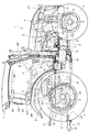
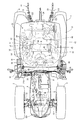
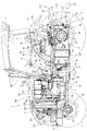
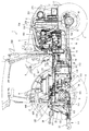
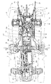
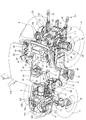
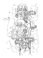
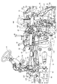
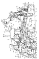
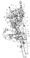
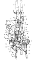
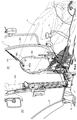
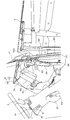
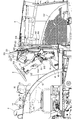
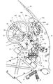
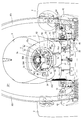
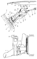
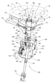
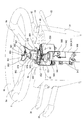
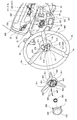
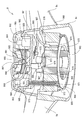
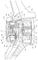
- FIG. 1 It is sectional drawing which shows the structure inside a dashboard. It is an expanded sectional view which shows the structure inside a dashboard. It is a left view which shows the structure inside a cabin. It is a perspective view which shows the structure inside a dashboard. It is the figure which looked ahead from the control seat. It is a front view of the meter panel seen from the control seat. It is a figure which shows the telescopic operation
- FIGS. 1 to 8 the traveling machine body 2 of the tractor 1 is supported by a pair of left and right rear wheels 4 as well as a pair of left and right front wheels 3 as a traveling portion.
- the pair of left and right rear wheels 4 corresponds to the rear traveling unit.
- a diesel engine 5 (hereinafter simply referred to as an engine) is mounted on the front portion of the traveling machine body 2, and the tractor 1 is configured to travel forward and backward by driving the rear wheel 4 or the front wheel 3 with the engine 5.
- the engine 5 is covered with a bonnet 6.
- a cabin 7 is installed on the upper surface of the traveling machine body 2.
- Steps 10 on which the operator gets on and off are provided on the left and right outer sides of the cabin 7.
- a fuel tank 11 for supplying fuel to the engine 5 is provided below the bottom of the cabin 7.
- the traveling machine body 2 includes an engine frame 14 having a front bumper 12 and a front axle case 13, and left and right machine body frames 15 detachably fixed to a rear portion of the engine frame 14.
- a front axle 16 is rotatably protruded outward from the left and right ends of the front axle case 13.
- the front wheels 3 are attached to the left and right ends of the front axle case 13 via the front axle 16.
- a transmission case 17 is connected to the rear part of the body frame 15 for appropriately changing the rotational power from the engine 5 and transmitting it to the front and rear four wheels 3, 3, 4, 4.
- a tank frame 18 having a rectangular frame plate shape in a bottom view projecting outward in the left and right directions is bolted to the lower surface sides of the left and right body frames 15 and the mission case 17.
- the fuel tank 11 of the embodiment is divided into left and right two parts.
- the left and right fuel tanks 11 are distributed and mounted on the upper surface side of the left and right projecting portions of the tank frame 18.
- Left and right rear axle cases 19 are mounted on the left and right outer surfaces of the mission case 17 so as to protrude outward.
- Left and right rear axle cases 20 are rotatably inserted in the left and right rear axle cases 19.
- the rear wheel 4 is attached to the mission case 17 via the rear axle 20.
- Upper portions of the left and right rear wheels 4 are covered with left and right rear fenders 21.
- a hydraulic lifting mechanism 22 that lifts and lowers a ground working machine (not shown) such as a rotary tiller is detachably attached.
- the ground work machine is connected to the rear portion of the transmission case 17 via a three-point link mechanism 111 including a pair of left and right lower links 23 and a top link 24.
- a PTO shaft 25 for projecting a PTO driving force to a ground working machine such as a rotary tiller is provided to project rearward.
- a flywheel 26 (see FIGS. 4 to 6, 10, and 11) is connected to an output shaft (piston rod) of the engine 5 that protrudes backward from the rear side surface of the engine 5.
- a main shaft 27 projecting rearward from the flywheel 26 and a main transmission input shaft 28 projecting forward from the front side of the transmission case 17 are connected via a power transmission shaft 29 having universal shaft joints at both ends. (See FIGS. 4 to 6).
- a hydraulic continuously variable transmission 500, a forward / reverse switching mechanism 501, travel transmission gear mechanisms 502, 503, 504, a rear wheel differential gear mechanism 506, and the like are arranged inside the mission case 17. Yes.
- the rotational power of the engine 5 is transmitted to the main transmission input shaft 28 of the transmission case 17 via the main driving shaft 27 and the power transmission shaft 29, and is shifted by the hydraulic continuously variable transmission 500 and the traveling transmission gear mechanism. Is transmitted to the left and right rear wheels 4 via the rear wheel differential gear mechanism 506.
- the front wheel output shaft 30 projecting forward from the front lower part of the transmission case 17 is transmitted to the front wheel projecting rearward from the front axle case 13 containing the front wheel differential gear mechanism 507 via the front wheel drive shaft 31.
- the shaft 508 is connected. Transmission power by the hydraulic continuously variable transmission 500 and the traveling transmission gear mechanism (two-wheel drive / four-wheel drive switching mechanism 504) in the mission case 17 is transmitted from the front wheel output shaft 30, the front wheel drive shaft 31, and the front wheel transmission shaft 508 to the front axle. It is configured to be transmitted to the left and right front wheels 3 via a front wheel differential gear mechanism 507 in the case 13.
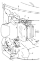
- a steering column 32 is disposed in front of the control seat 8 in the cabin 7.
- the steering column 32 is erected on the rear side of a dashboard 33 disposed on the front side inside the cabin 7.
- a steering handle 9 having a substantially round shape in plan view is attached to the upper end side of the handle shaft that protrudes upward from the upper surface of the steering column 32.
- a pair of left and right brake pedals 35 for braking the traveling machine body 2 are disposed on the lower right side of the steering column 32.
- a forward / reverse switching lever 36 (reverser lever) for switching the traveling direction of the traveling machine body 2 between forward and reverse is disposed.
- a clutch pedal 37 for disengaging the outputs of the hydraulic continuously variable transmission 500 (forward low speed hydraulic clutch 537, forward high speed hydraulic clutch 539, reverse hydraulic clutch 541) is disposed.
- the master control solenoid valve 635 is turned on by stepping on the clutch pedal 37, and the forward output or the reverse output of the hydraulic continuously variable transmission 500 is cut off (see FIG. 14).
- An erroneous operation preventing body 38 (reverser guard) extending along the forward / reverse switching lever 36 is disposed on the left side of the steering column 32 and below the forward / reverse switching lever 36.
- the erroneous operation preventing body 38 which is a contact prevention tool, to protrude outward from the forward / reverse switching lever 36, the operator is prevented from inadvertently contacting the forward / reverse switching lever 36 when getting on and off the tractor 1.
- An operation display panel 39 incorporating a liquid crystal panel is provided on the upper rear side of the dashboard 33.
- Accelerator pedal 41 for controlling the rotational speed of the engine 5 or the vehicle speed is disposed on the right side of the steering column 32 on the floor plate 40 in front of the control seat 8 in the cabin 7. Note that substantially the entire top surface of the floor plate 40 is formed as a flat surface. Left and right side columns 42 are arranged on both left and right sides of the control seat 8.
- a parking brake lever 43 that maintains the left and right rear wheels 4 in a braking state, and an ultra-low speed that forcibly and significantly reduces the forward travel speed (vehicle speed) of the tractor 1
- a lever 44 creep operation lever
- a sub-transmission lever 45 that switches the output range of the traveling sub-transmission gear mechanism 503 in the mission case 17, and a PTO transmission lever 46 that switches the driving speed of the PTO shaft 25 are arranged.
- a differential lock pedal 47 for turning on and off the differential drive of the left and right rear wheels 4 is disposed below the control seat 8.
- a reverse PTO lever 48 for performing an operation of driving the PTO shaft 25 in the reverse direction is disposed on the left rear side of the control seat 8 (see FIG. 10).
- the armrest 49 includes a main transmission lever 50 that increases / decreases the traveling speed of the tractor 1, a dial type work unit position dial 51 (elevating dial) that manually changes and adjusts the height position of a ground work machine such as a rotary tiller. It has.
- the armrest 49 is configured to be able to be turned up and rotated in a plurality of stages with the rear end lower part as a fulcrum.
- a throttle lever 52 that sets and holds the rotational speed of the engine 5
- a PTO clutch switch 53 that interrupts power transmission from the PTO shaft 25 to a work machine such as a rotary tiller
- a plurality of hydraulic operation levers 54 (SCV levers) for switching the hydraulic external take-off valve 430 (see FIG. 14) arranged on the upper surface side of the mission case 17 are arranged.
- the hydraulic external take-off valve 430 is for controlling supply of hydraulic oil to hydraulic equipment of a work machine such as a front loader that is retrofitted to the tractor 1.
- four hydraulic operation levers 54 are arranged in accordance with the number of hydraulic external take-out valves (four stations).
- left and right front support bases 96 that support the front side of the cabin 7 and left and right rear support bases 97 that support the rear part of the cabin 7 are provided.
- the front support 96 is bolted to the front and rear intermediate portions of the outer side surfaces of the left and right aircraft frames 15, and the front bottom of the cabin 7 is anti-vibrated on the upper surface of the front support 96 via the anti-vibration rubber body 98.
- the rear support base 97 is bolted to the middle portion of the left and right widths of the upper surfaces of the left and right rear axle cases 19 that are horizontally extended in the left-right direction, and the vibration-proof rubber body 99 is attached to the upper surface side of the rear support base 97.
- the rear bottom portion of the cabin 7 is supported by vibration isolation. That is, the diesel engine 5 and the cabin 7 are supported by the traveling machine body 2 (the engine frame 14, the machine frame 15, and the rear axle case 19, which are integrally connected) via the plurality of vibration-proof rubber bodies. . Further, as shown in FIGS. 4 and 5, etc., the rear support base 97 is disposed on the upper surface side of the rear axle case 19, and the steady bracket 101 is disposed on the lower surface side of the rear axle case 19.
- the fastening bracket 101 is fastened with bolts, and both ends of the steady rod body 103 with turnbuckles that can be expanded and contracted are connected to the middle portion of the lower link 23 and the steady bracket 101 that extend in the front-rear direction. The horizontal vibration of 23 is prevented.
- the diesel engine 5 has a cylinder head mounted on a cylinder block having a built-in engine output shaft and piston, and is connected to an air cleaner 221 via a turbocharger 211 on the right side surface of the diesel engine 5 (cylinder head). And an EGR device 210 that recirculates a part of the exhaust gas from the exhaust manifold 204, and a part of the exhaust gas discharged to the exhaust manifold 204 is returned to the intake manifold 203. The maximum combustion temperature during high-load operation is lowered, and NOx (nitrogen oxide) emissions from the diesel engine 5 are reduced.
- NOx nitrogen oxide
- the exhaust manifold 204 connected to the tail pipe 229 and the turbocharger 211 are arranged on the left side surface of the diesel engine 5 (cylinder head). That is, the intake manifold 203 and the exhaust manifold 204 are distributed and arranged on the left and right side surfaces along the engine output shaft in the engine 5.
- a cooling fan 206 is disposed on the front side of the diesel engine 5 (cylinder block).
- the diesel engine 5 includes a continuously regenerative exhaust gas purification device 224 (DPF) disposed on the upper surface side (above the exhaust manifold 204) of the diesel engine 5, and exhaust gas.
- a tail pipe 229 is connected to the exhaust side of the purification device 224.
- the exhaust gas purifying device 224 removes particulate matter (PM) in the exhaust gas discharged from the engine 5 through the tail pipe 229 to the outside of the machine, and at the same time, carbon monoxide (CO) and carbonization in the exhaust gas.
- Hydrogen (HC) is configured to be reduced.
- the bonnet 6 has a front grill 231 at the front lower side, and covers the upper surface side and the front surface side of the engine room 200.
- Side engine covers 232 formed of a perforated plate are arranged on the lower left and right sides of the bonnet 6 to cover the left and right sides of the engine room 200. That is, the hood 6 and the engine cover 232 cover the front, upper, and left and right sides of the diesel engine 5.
- a radiator 235 having a fan shroud 234 attached to the back side is erected on the engine frame 14 so as to be positioned on the front side of the engine 5.
- the fan shroud 234 surrounds the outer peripheral side of the cooling fan 206 and allows the radiator 235 and the cooling fan 206 to communicate with each other.
- An air cleaner 221 is disposed above the front surface of the radiator 235.
- an oil cooler, a fuel cooler, and the like are installed on the front side of the radiator 235.
- an engine control device (engine ECU) 271 is disposed in front of a heat exchanger such as the radiator 235.
- the engine ECU 271 receives sensor signals from the sensors of the engine 5 and controls driving of the engine 5.
- the engine control device 271 is erected on the frame bottom plate 233 along the longitudinal direction of the traveling machine body 2 (longitudinal direction of the engine frame 14).
- the pair of left and right body frames 15 are connected by a support beam frame 236.
- the support beam frame 236 is bolted to the left and right airframe frames 15 and is erected on the front end portions (rear side of the engine 5) of the left and right airframe frames 15, and the rear engine legs 237 having vibration-proof rubber bodies.
- the rear part of the diesel engine 5 is connected to the upper surface of the support beam frame 236 via As shown in FIGS. 1, 2, 4, 5, 11, and 12, left and right front engine legs 238 having anti-vibration rubber bodies are provided in the middle of the pair of left and right engine frames 14.
- the left and right side surfaces of the front part of the diesel engine 5 are connected to each other. That is, the front side of the diesel engine 5 is supported on the engine frame 14 by vibration isolation, and the rear part of the diesel engine 5 is supported on the front end sides of the pair of left and right body frames 15 via the support beam frame 236.
- the transmission case 17 includes a front transmission case 112 having a main transmission input shaft 28 and the like, a rear transmission case 113 having a rear axle case 19 and the like, and a front side of the rear transmission case 113 on the rear side of the front transmission case 112.
- An intermediate case 114 to be connected is provided.
- the rear ends of the left and right machine body frames 15 are connected to the left and right side surfaces of the intermediate case 114 via the left and right upper and lower machine body connecting shafts 115 and 116.
- the rear end portions of the left and right airframe frames 15 are connected to the left and right side surfaces of the intermediate case 114 by the two upper airframe connecting shaft bodies 115 and the two lower airframe connecting shaft bodies 116.
- the transmission case 17 is integrally connected to form the rear part of the traveling machine body 2, and the front transmission case 112 or the power transmission shaft 29 is disposed between the left and right machine body frames 15, so that the front transmission case is provided. 112 and the like are protected.
- the left and right rear axle cases 19 are attached to the left and right sides of the rear transmission case 113 so as to protrude outward.
- the intermediate case 114 and the rear transmission case 113 are made of high-rigid cast iron, while the front transmission case 112 is made of aluminum die cast that is lightweight and has good workability.
- the transmission case 17 is divided into the three parts of the front transmission case 112, the intermediate case 114, and the rear case 113, parts such as shafts and gears are attached to the cases 112 to 114, respectively.
- the front transmission case 112, the intermediate case 114, and the rear transmission case 113 can be assembled. Therefore, the assembly of the mission case 17 can be performed accurately and efficiently.
- the left and right rear axle cases 19 are attached to the left and right sides of the rear transmission case 113, and the middle of the high-rigidity structure connecting the front transmission case 112 and the rear transmission case 113 to the left and right body frames 15 constituting the traveling vehicle body 2. Since the case 114 is connected, for example, with the intermediate case 114 and the rear transmission case 113 attached to the body frame 15, only the front transmission case 112 is removed, and a hydraulic continuously variable transmission (not shown) or the like is installed. Maintenance or repair work such as replacement of a shaft or gear inside the provided front transmission case 112 can be performed. Therefore, the frequency of the disassembling work for removing the entire mission case 17 from the tractor 1 can be remarkably reduced, and the workability at the time of maintenance and repair can be improved.
- the intermediate case 114 and the rear transmission case 113 are made of cast iron, and the front transmission case 112 is made of aluminum die cast, the intermediate case 114 connected to the body frame 15 and the left and right rear axle cases 19 are made.
- the rear transmission case 113 to which the two are connected can be configured with high rigidity as a strength member constituting the traveling machine body 2.
- the front transmission case 112 that is not a strength member can be reduced in weight. Therefore, it is possible to reduce the weight of the transmission case 17 as a whole while sufficiently securing the rigidity of the traveling machine body 2.
- the hydraulic lifting mechanism 22 includes left and right hydraulic lift cylinders 117 that are controlled by operation of the working unit position dial 51 and the upper surface of the rear transmission case 113 of the transmission case 17.
- the left and right lift arms 120 are connected to the left and right lower links 23, and the left and right lift arms 120 are pivotally supported via a lift fulcrum shaft 119 on an openable and closable upper surface lid 118.
- Left and right lift rods 121 are provided.
- a part of the right lift rod 121 is formed by a horizontal cylinder 122 for hydraulic control, and the length of the right lift rod 121 is configured to be adjustable by the horizontal cylinder 122.
- the top link hinge 123 is fixed to the back side of the top cover 118, and the top link 24 is connected to the top link hinge 123 via a hinge pin.
- the piston of the horizontal cylinder 122 is expanded and contracted to change the length of the right lift rod 121.
- the angle is configured to change.
- the cabin 7 that covers the control seat 8 on the traveling machine body 2 includes a cabin frame 300 that forms a framework.
- the cabin frame 300 includes a pair of left and right front columns 301 positioned in front of the control seat 8, a pair of left and right rear columns 302 positioned behind the control seat 8, and a front beam that connects between the upper ends of the front columns 301.
- It is a box frame.
- a roof body 306 is detachably attached to the upper end side of the cabin frame 301, that is, on a rectangular frame constituted by the front beam member 303, the rear beam member 304, and the left and right side beam members 305.
- the longitudinal ends of the left and right bottom frames 311 extending in the front-rear direction are connected to the lower ends of the front column 301 and the rear column 302.
- the floor plate 40 is stretched on the upper surface side of the left and right bottom frames 311, the dashboard 33 is erected on the front end side of the floor plate 40, and the steering handle 9 is installed on the rear surface side of the dashboard 33 via the steering column 32.
- a brake pedal 35 and the like are disposed on the front upper surface side of the floor board 40, and the control seat 8 is attached to the rear upper surface side of the floor board 40.
- a front window glass 321 is arranged on the front side of the cabin frame 300, that is, in the region of the front portion of the cabin 7 surrounded by the left and right front columns 301, the front beam member 303, and the front end of the floor board 40.
- a rear window glass 322 is disposed on the rear surface side of the cabin frame 300, that is, on the rear upper portion of the cabin 7 surrounded by the left and right rear columns 302 and the rear beam member 304.
- Left and right side doors 323 made of transparent glass are disposed in the left and right side surfaces of the cabin frame 300, that is, in the region of the side of the cabin 7 surrounded by the front struts 301 and the rear struts 302 arranged in the front-rear direction.
- Each side door 323 is attached to the corresponding rear column 302 through a pair of upper and lower hinges 324 so as to be opened and closed.
- the columns 301 and 302 and the beam members 303, 304, and 305 are arranged on the sides of the cabin 7 (cabin frame 300).
- the cabin 7 cabin frame 300.
- a front window glass 321, a rear window glass 322, and left and right side doors 323 made of transparent glass are disposed on the front, rear, left and right side surfaces of the cabin frame 300.
- the front side of the dashboard 33 is covered with a heat shield plate (air cut plate) 901 for shielding heat from the engine 5 and the like under the bonnet 6.
- the front window glass 321 is composed of a single glass plate, and an air cut plate 901 is connected to the back surface of the front window glass 321.
- a urethane material 902 having both heat insulation and sound insulation is stretched on the front surface of the windshield 321.
- the dashboard 33 includes a wiper drive mechanism 422 that covers the rear of the windshield 321.
- the wiper drive mechanism 422 includes a drive motor that generates rotational power to the wiper 421 that is pivotally supported by the windshield 321 and a gear mechanism that transmits the rotational power of the drive motor to the wiper 421. As the drive motor in the wiper drive mechanism 422 rotates, the rotation of the drive motor is transmitted to the wiper 421 via the gear mechanism, and the wiper 421 rotates along the surface of the windshield 321.
- the wiper drive mechanism 422 is connected and fixed to the air cut plate 901. That is, the wiper drive mechanism 422 is fixed to the rear surface of the air cut plate 901, and the front window glass 321 is stretched on the front side of the air cut plate 901. Then, the drive shaft 422 a of the wiper drive mechanism 422 is passed through the windshield 321. The wiper 421 is rotated by the wiper drive mechanism 422 when the drive shaft 422 a of the wiper drive mechanism 422 pivotally supports the wiper 421.
- a urethane material (sound insulating material) 902 surrounded by a sheet metal frame is stretched in a region facing the air cut plate 901 on the front surface of the windshield 321 via a sealing material. Then, the drive shaft 422 a of the wiper drive mechanism 422 is passed through the urethane material 902.
- a meter control device (meter ECU) 904 and an antenna 905 are fixed to the rear surface of the air cut plate 901 together with the wiper drive mechanism 422. By attaching the wiper drive mechanism 422, the meter ECU 904, and the antenna 905 to the air cut plate 901, the air cut plate 901 can be configured as one unit, so that the assembling operation of each component inside the dashboard 33 can be simplified.
- the dashboard 33 includes an inner board (inner board) 33a and an outer board (outer cover) 33b.
- the outer peripheral edge of the inner board 33a is connected to the outer peripheral edge of the air cut plate 901, and the inner board 33a is fixed to the back surface of the air cut plate 901.
- the dashboard 33 is formed by fitting the outer board 33b from the upper side of the inner board 33a so as to cover the upper part of the inner board 33a.
- An opening 33c is provided on the upper center side of the inner board 33a, and the meter panel 906 is fixed to the front surface of the inner board 33a so that the display surface of the meter panel 905 fits in the opening 33c.
- the inner board 33a has a shape in which the outer peripheral portion of the opening 33c is raised, so that the outer side of the display portion of the meter panel 906 is surrounded by the side wall 33d.
- the meter panel 906 is disposed in a state where the panel surface is inclined slightly upward from the rear so as to face the operator seated on the control seat 8 at a position on the lower front side of the control handle 9.
- the outer edge of the meter panel 906 is covered with a side wall 33d of the inner board 33a raised from the inside toward the outside.
- a plurality of switch members 907 such as a parking switch and a wiper switch are arranged at a position on the outer periphery of the meter panel 906, for example.
- the key switch 61 is a rotary switch that can be rotated with a predetermined key inserted into the keyhole, and is attached to the right side of the steering handle 9 on the dashboard 33.
- the meter panel 906 has a liquid crystal panel 908 that displays characters in the center display area as a driving operation display device, and an engine tachometer 909 that indicates the rotational speed of the engine 5 with a pointer on the outer periphery of the liquid crystal panel 908. Provided.
- the meter panel 906 has a fuel meter 910 that indicates the remaining amount of fuel as a pointer on the left side of the engine tachometer 909, and a water temperature meter 911 that indicates the cooling water temperature of the engine 5 as a pointer on the right side of the engine tachometer 910. It is arranged.
- the meter panel 906 has a plurality of display lamps 912 and 913 formed by LEDs or the like in the display area on the left and right outside of the engine tachometer 909 (outside the center display area).
- the display lamp 912 disposed on the left side of the engine tachometer 909 functions as, for example, a warning lamp or a display lamp related to the traveling system.
- the display lamp 913 disposed on the right side of the engine tachometer 909 acts as a warning lamp or a display lamp for the work system.
- one of the left and right display lamps 912 and 913 acts as a warning light due to a minor failure, and the other acts as a warning light due to a severe failure.
- one of the display lamps 912 is assigned to a regeneration lamp indicating a regeneration processing state of the exhaust gas purification device 224.
- the steering column 32 is installed so as to be surrounded by the inner board 33b, and stands upright so as to be embedded in the back side of the dashboard 33.
- a vertically long steering shaft 738 is supported in the steering column 32.
- the steering shaft 738 protrudes upward from the upper surface of the steering column 32 at the upper end of the handle shaft 921, and the steering handle 9 having a substantially round shape in plan view is attached to the upper end side of the handle shaft 921.
- the distal end side of a vertically long connecting shaft 740 is connected to the lower end side of the handle shaft 921 through a universal joint 922.
- An operation shaft 742 of a power steering hydraulic mechanism 621 supported on the lower side of a board support plate (air cut plate) 901 is connected to the base end side of the connection shaft 740 via a universal joint 741.
- a tilt lever 915 and a telescopic lever 914 for adjusting the attitude of the steering handle 9 are arranged separately on the left and right of the steering column 32 where the steering handle 9 is arranged. That is, a telescopic lever 914 that is pivotally supported in the lateral direction and pivoted in the front-rear direction is provided on the right side surface of the steering column 32. A tilt lever 915 is provided below the left side surface of the steering column 32 and is pivotally supported in the horizontal direction and rotated in the front-rear direction. Further, a telescopic mechanism 917 for moving the steering handle 9 in the axial direction of the handle shaft 921 and a tilt mechanism 918 for tilting the steering handle 9 together with the handle shaft 921 are provided in the steering column 32.
- a brake pedal support mechanism 916 including a brake pedal shaft 720 that pivotally supports the left and right brake pedals 35 is disposed in front of the steering column 32.
- the brake pedal support mechanism 916 is connected and supported in the middle of the air cut plate 901.
- the tilt mechanism 915 is installed below the steering column 32 and pivotally attached to a fixed bracket 919 connected to the brake pedal support mechanism 916. That is, the tilt mechanism 918 is pivotally supported by a fixed bracket 919 fixed to the air cut plate 901 via the brake pedal support mechanism 916.
- a telescopic mechanism 917 that can be expanded and contracted by a multi-axis structure is provided above the tilt mechanism 918. Further, the steering column 32 is connected to the distal end side of the telescopic mechanism 917.
- the operator releases the fixation by the telescopic mechanism 917 by rotating the telescopic lever 914 toward the front, and the steering handle 9 can be moved along the axial direction of the handle shaft 921, as shown in FIG.
- the height position of 9 can be adjusted.
- the steering column 32 since the steering column 32 is fixed to the distal end side of the telescopic mechanism 915, the steering column 32 can be moved up and down together with the operation handle 9.
- the tilt mechanism 918 can tilt the steering handle 9 together with the handle shaft 921 by using the connecting portion between the lower end of the handle shaft 921 and the universal joint 922 as an axis.
- the telescopic mechanism 917 sandwiches the column jacket 923 that supports the handle shaft 921, the outer cover 924 that holds the column jacket 923 from the upper side, and both sides of the slit provided on the lower edge of the outer cover 924.
- a loose fastening member 925 provided so as to be recessed.
- the handle shaft 921 is configured such that a lower shaft 926 connected to a universal joint 922 is coaxially inserted into a cylindrical upper shaft 927, and the lower shaft 926 and the upper shaft 927 are spline-fitted or serrated fitted. Yes. Therefore, the handle shaft 921 allows the upper shaft 927 to slide along the axial direction with respect to the fixed lower shaft 926, and also allows the rotation from the upper shaft 927 to be transmitted to the lower shaft 926. With respect to the shaft.
- the column jacket 923 is configured such that an upper jacket in which an upper shaft 926 is pivotally supported by a bearing is slidable in an axial direction with respect to a lower jacket that is pivotally supported by a lower shaft 927 and is fixed to a movable bracket 931 described later.
- the outer cover 924 has a cylindrical shape connected to the upper upper end of the column jacket 923, and has a slit cut in the axial direction from its lower edge. Therefore, the upper jacket and the outer cover 924 of the column jacket 923 can move in the axial direction together with the upper shaft 927. Further, by fixing the lower jacket of the column jacket 923 to the movable bracket 931, the telescopic mechanism 917 tilts together with the handle shaft 921 due to the tilt of the movable bracket 931.
- the loose tightening member 925 has a fixing bolt 928 connected to one end of the telescopic lever 914 inserted into a pair of fixing plates 929 connected to both sides of the slit of the outer cover 924, and a pair of fastening cams 930 receives a pair of fixing bolts 929.
- the distance between the fixing plates 929 is changed. That is, by interlocking the fixing bolt 928 with the rotation of the telescopic lever 914, the outer cover 924 is loosely tightened by moving the pair of fixing plates 929 apart or close by the tightening cam 930, and the telescopic mechanism 917. Unfix or fix.
- a restriction groove is provided in the lower jacket of the column jacket 923, and a restriction bolt fastened to the upper jacket and the outer cover 924 of the column jacket 923 is engaged with the restriction groove, whereby a telescopic mechanism 917 is obtained.
- the movement range by is regulated.
- the tilt mechanism 918 supports the movable bracket 931 through which the handle shaft 921 penetrates the fixed bracket 919, and is provided with a fixing member 932 that fixes the tilting posture of the movable bracket 931.
- the movable bracket 931 has a substantially triangular shape on both the left and right side surfaces, and one of its apexes is pivotally supported by the fixed bracket 919, and the rear edge is connected to the upper edge of the fixed bracket 919 by a coil spring 933 and biased.
- a telescopic mechanism 917 is fixed to the upper surface of the movable bracket 931 through which the handle shaft 921 is passed. Accordingly, by tilting the movable bracket 931 with respect to the fixed bracket 919, the handle shaft 921 and the telescopic mechanism 917 tilt with the universal joint 922 as the center.
- the fixed member 932 is provided with tilt levers 915 and cams 935 at both ends of a support shaft 934 that is supported by a fixed bracket 919, and a fixing arm 937 engaged with a positioning plate 936 fixed to the movable bracket 931 is fixed bracket. 919 is pivotally supported.
- the fixing arm 937 is connected to the support shaft 934 by the coil spring 938 and is connected to the positioning plate 935 by the coil spring 939 and is urged by the support shaft 934 and the positioning plate 936, respectively.
- the fixing arm 937 includes a hole that comes into contact with the outer peripheral surface of the cam 935, and the fixing arm 937 is rotated by the rotation of the cam 935.
- the steering column 32 since the steering column 32 is fixed to the distal end side of the telescopic mechanism 917, the steering column 32 can be moved up and down (telescopic operation) and tilted (tilt operation) together with the operation handle 9. That is, the posture of the steering column 32 is changed in conjunction with the posture adjustment of the steering handle 9. Therefore, the support positions of the switches 64 and 65 and the levers 36, 62 and 63 arranged on the upper surface side of the steering column 32 are adjusted in conjunction with the steering handle 9. Accordingly, the switches 64 and 65 and the levers 36, 62, and 63 can be supported at positions that are easy to operate in accordance with the field of view of the operator who sits down.
- the steering column 32 has a forward / reverse switching lever 36 projecting from the left side thereof, and an erroneous operation prevention body 38 (reverser guard) is disposed below the forward / reverse switching lever 36. Further, the steering column 32 is provided with operation levers 62 and 63 such as a wiper lever for driving the wiper 421 and an auto cruise lever for driving the work vehicle at a constant speed on the right side surface thereof.
- a DPF regeneration switch 62 for executing regeneration control of the exhaust gas purifying device 224 is provided on the upper surface of the steering column 32 at the base of the steering handle 9. That is, the DPF regeneration switch 62 is disposed in the operator's field of view when in a straight-ahead working posture. Therefore, the position and lighting display state of the DPF regeneration switch 64 can be easily visually recognized by a seated operator without the DPF regeneration switch 62 being hidden by the steering handle 9 or the operation levers 36, 62, and 63.
- the telescopic mechanism 917 in the steering shaft 738 has a plurality of component mounting stays 941 to 943 and a screw receiving member 944 fixed to the outer peripheral surface of the outer cover 924 by welding or the like.
- the upper end side stay 941 provided at the upper end of the outer cover 924 fastens and fixes the lever switch unit 945 including the operation lever 62.
- the right stay 942 provided below the upper end side stay 941 on the right side surface of the outer cover 924 fastens and fixes the lever switch unit 946 including the operation lever 63.
- a left stay 943 provided below the right stay 941 on the left side surface of the outer cover 924 fastens and fixes the erroneous operation preventing body 38.
- the lever switch unit 947 provided with the forward / reverse switching lever 36 is fastened and fixed to the upper surface of the erroneous operation preventing body 38. That is, the lever switch unit 947 for the forward / reverse switching lever 36 is connected to the left stay 943 via the erroneous operation preventing body 38.
- the steering column 32 is fixed to the telescopic mechanism 917 by bolting to screw receiving portions 948 and 949 provided at the front and rear edges of the upper end side stay 941 and a screw receiving member 944.
- the upper end side stay 941 fastens and fixes the terminal stay 950 so as to cover the lever switch unit 945 fixed to the upper surface thereof.
- the terminal stay 950 is connected to the front end and the rear end of the upper end side stay 941 and is fixed so as to straddle the lever switch unit 945.
- the terminal stay 950 has an opening in the central region thereof, and is configured such that the tip of the handle shaft 921 covered with the telescopic mechanism 917 can pass therethrough.
- the terminal stay 950 has a first brush 951 and a second brush 952 that are electrically connected to a harness (not shown) on the surface around the opening, and are arranged at different positions around the handle shaft 921.
- the first brush 951 is electrically connected to the outer peripheral surface of the front end of the handle shaft 921 by contacting the metal portion at the front end of the handle shaft 921 so as to sandwich it.
- the second brush 952 is disposed at a position separated from a boss 963 described later, and a midway portion is fixed to the terminal stay 950 and connected to a harness (not shown), while both ends are bent toward the steering handle 9 to be described later.
- the slip ring 964 is brought into contact with the bottom surface to be electrically connected to the slip ring 964.
- a plurality of switches 65 such as work switches and one-touch automatic switches are arranged on the upper surface of the steering column 32 at positions that are symmetrical with respect to the handle shaft 921 of the steering handle 9. Therefore, the operator who sits down can easily confirm the positions of the switch for work and the one-touch automatic switch by visually recognizing the switch group 65 arranged on the upper surface of the steering column 32, so that erroneous operations can be reduced.
- a DPF regeneration switch 64 and a switch 65 such as a work switch and a one-touch automatic switch are provided on the upper surface of the steering column 32 at the base of the steering handle 9.
- a DPF regeneration switch 64 is provided on the upper surface of the steering column 32 above the brake pedal 35.
- the switches 65 and 65 by the work switch and the one-touch automatic switch are installed with the spoke of the steering handle 9 arranged on the front and rear center line of the traveling machine body 2 interposed therebetween.
- the switch 65 disposed on the left side is a work switch
- the switch 66 disposed on the right side is a one-touch automatic switch.
- the steering handle 9 has a shape in which a circular steering wheel 9b is arranged outside a Y-shaped spoke 9a whose center (hub 9c) is pivotally supported by the steering column 32. Accordingly, the steering handle 9 can be configured such that the region surrounded by the spoke 9a and the steering wheel 9b is a region 9x, 9y, 9z that can be viewed by the operator.
- the meter panel 905 is disposed in a region 9x sandwiched between the two upper spokes 9a.
- the switches 65 and 65 provided on the steering column 32 are arranged to be distributed to the left and right in the regions 9y and 9z that are distributed to the left and right around the lower one spoke 9c.
- a 4WD / double speed / 2WD switching switch 65a, a turning automatic changeover switch 65b, and a turning up / reverse up changing switch 65c are arranged at a position corresponding to the viewable region 9y on the steering column 32.
- a first automatic operation switch 65d, a display changeover switch 65e, and a second automatic operation switch 65f are arranged at a position corresponding to the visually recognizable area 9z on the steering column 32.
- the 4WD / double speed / 2WD switching switch 65a is a switch that accepts switching between the 4WD driving mode, the double speed driving mode, and the 2WD driving mode.
- the turning automatic changeover switch 65b is a switch for accepting the change of the vehicle speed or the engine speed during turning and straight running.
- the turning up / reverse up switching switch 65c is a switch for designating the execution timing of the automatic lifting of the working unit by the hydraulic lifting mechanism 22.
- the first automatic work switch 65d is a switch for collectively turning ON / OFF reverse drive control, turning control, vehicle speed or rotation speed switching control, automatic braking control during turning, and the like.
- the display changeover switch 65e is a switch that accepts display changeover of the liquid crystal panel 908 in the meter panel 906.
- the second automatic work switch 65f is a switch for collectively turning on / off automatic rotary control, engine load control, pitching control of the working unit, and the like.
- the steering handle 9 includes a handle body 960 in which a rim (steering wheel) 9b is connected to the other end of the spoke 9a that is radially arranged outward from the hub 9c, and a hub of the handle body 960.
- a hub cover 961 that covers the upper surface of 9c and a part of the spoke 9a, and a cap 962 that covers the upper surface of the hub cover 961 are provided.
- the handle body 960 includes a cylindrical boss 963 at the center of the hub 9c, and is fixed to the distal end of the handle shaft 921 by fitting the boss 963 to the distal end portion of the handle shaft 921.
- the hub cover 961 is fastened to the handle body 960 by screws 965 and is fixed on the handle body 960.
- the cap 962 is provided with a locking portion 966 having a hook shape at the lower end protruding below the outer peripheral edge (on the hub cover 961 side).
- the locking portion 966 is provided in a locking groove 967 provided on the hub 9c of the handle body 960. 966 is locked.
- the locking groove 967 is configured in a cross-sectional shape having a top edge bent toward the inner periphery so as to be locked with the lower end of the locking portion 966 bent outward.
- the hub cover 961 is provided with a locking through hole 968 in the outer peripheral portion so as to be in the same phase as the locking portion 966 of the cap 962 and the locking groove 967 of the handle body 960 in the circumferential direction.
- the locking portion 966 of the cap 962 passes through the locking through hole 968 of the hub cover 961 and locks with the locking groove 967 of the handle main body 960, so that the cap 962 is interposed between the hub cover 961 and the handle main body 960. Is fixed to the handle main body 960.
- the handle main body 960 is provided with a ring-shaped ring fixing member 969 on the lower surface of the hub 9c, and the slip ring 964 is fixed by projecting the outer peripheral edge of the lower surface of the ring fixing member 969 downward.
- the handle main body 960 has a through hole for fixing a boss 963 for inserting a cylindrical boss 963 at the center of the hub 9c, and a through hole 971 for fixing a plurality of screw receivers 972 on the outer periphery of the through hole 970 for fixing the boss 963.
- the ring fixing member 969 has a plurality of screw receivers 972 protruding from the upper surface thereof, and is fixed to the lower surface of the hub 9c by inserting the screw receivers 972 into the through holes 971 of the handle main body 960.
- the hub cover 961 has a plurality of screw receivers 973 arranged at equal intervals along the circumferential direction and projecting downward.
- the screw receiver 973 of the hub cover 961 is disposed at a position corresponding to the screw receiver 972 of the handle body 960.
- the screw receiver 972 of the ring fixing member 969 and the screw receiver 973 of the hub cover 961 overlap vertically.
- the hub cover 961 and the ring fixing member 969 are fixed to the handle body 960 by screwing the screws 965 into the screw receivers 972 and 973.
- a through hole 974 that penetrates the handle main body 960 and the ring fixing member 969 in the axial direction is provided, and a contact 975 protruding upward from the inner edge of the slip ring 964 is inserted.
- the hub 9c and the ring fixing member 969 of the handle body 960 are made of an insulating material, and the boss 963 made of a conductive material such as a metal part and the slip ring 964 are insulated by the hub 9c and the ring fixing member 969. .
- the upper surface side of the hub 9c of the handle body 960 has a shape in which the outer peripheral edge is erected on the upper side (hub cover 961 side) to form an outer peripheral wall 976, and the inner side of the outer peripheral wall 976 is recessed downward.
- terminal fixing projections 977 are provided at positions outside the outer peripheral edge of the through hole 974 and different from the through hole 974 in the circumferential direction.
- a ring terminal 978 having a ring shape equivalent to the upper surface of the boss 963 is provided on the upper surface of the boss 963.
- the ring terminal 978 includes a contact 979 with a part of the outer peripheral edge protruding outward.
- the contact 979 is fixed to the upper surface of the boss 963 by fitting the contact 979 into the terminal fixing protrusion 977.
- the contact 979 of the ring terminal 978 has a shape bent upward (to the hub cover 961 side).
- the hub cover 961 has a screw receiving portion 973 projecting downward from the lower surface, and the screw receiving portion 973 is brought into contact with the upper surface of the hub 9c of the handle main body 960 so that the space between the hub cover 961 and the handle main body 960 is made hollow.
- the hub cover 961 has a cylindrical spring holder 981 fitted into the coil spring 980 at the center of the upper surface thereof so as to protrude upward (cap 962 side), and an outer peripheral wall 982 is provided upright on the outer peripheral edge thereof.
- a cylindrical guide receiving seat 983 is erected on the outer surface of the upper surface of the hub cover 961 along the outer peripheral wall 982.
- a conical guide 984 protruding from the lower surface of the cap 961 is inserted into the guide hole of the guide receiving seat 983 of the hub cover 961 to fix the cap 961 to the hub cover 961.
- the hub cover 961 penetrates a part of the outer peripheral surface of the spring holder 981, and a leaf spring-like fixed contact 985 is inserted into the penetrating portion from the outside of the spring holder 981, and extends toward the center of the spring holder 981 (hub cover 961). It is installed.
- One end of the fixed contact 985 is fixed by a fixing pin 986 penetrating the outer portion of the spring holder 981, and one end of the harness 987 is fixed to the other end of the fixed pin 986.
- the other end of the harness 987 is connected to the contact 975 of the slip ring 964.
- the fixed contact 985 is electrically connected to the harness 987 via the fixed pin 986, while the slip ring 964 is electrically connected to the harness 987 in the handle body 960.
- the fixed contact 985 is electrically connected to the slip ring 964 via the fixed pin 986 and the harness 987.
- the cap 962 has a cylindrical spring holder 988 that is fitted into the coil spring 980 at the center of the lower surface of the cap 962 so as to protrude downward (to the hub cover 961 side), and an outer peripheral wall 989 is erected on the outer peripheral edge thereof. . A part of the outer peripheral wall 989 extends downward to provide a locking part 966.
- the locking part 966 passes through the hub cover 961 and locks to the handle body 960, and the cap 962 is locked to the handle body. 960 is fixed.
- the coil spring 980 has a spring holder 981 of the hub cover 961 inserted in the lower end side, and a spring holder 988 of the cap 962 inserted in the upper end side, and is arranged at the axial center position in the hollow portion between the cap 962 and the hub cover 961. As a result, the cap 962 is biased by the coil spring 980 against the hub cover 961.
- the cap 962 is provided with a contact fixing portion 991 for holding the movable contact 990 at the center of the lower surface thereof.
- the movable contact 990 is positioned above the fixed contact 985 of the hub cover 961, and a horn (not shown) that issues a warning sound or the like by the movable contact 990 and the fixed contact 985.
- a switch SW for electrically connecting / disconnecting is omitted.
- the cap 962 is biased upward by a coil spring 980 having one end fixed to the hub cover 961. However, the cap 962 is biased upward by locking the locking portion 966 with the locking groove 967 of the handle body 960. It is regulated.
- the operator can electrically connect the switch SW by bringing the movable contact 990 into contact with the fixed contact 985 by pressing the cap 962 toward the hub cover 961.
- the switch SW can be electrically disconnected by separating the movable contact 990 and the fixed contact 985 by the biasing force of the coil spring 980.
- the movable contact 990 is screwed to the contact fixing portion 991 together with one end of the harness 992, and is fixed to the center position of the lower surface of the cap 962 while being electrically connected to the harness 992.
- the other end of the harness 992 is connected to the contact 979 of the ring terminal 978 through the harness through hole 993 provided in the hub cover 961.
- the movable contact 990 is electrically connected to the harness 992 in the cap 962, while the boss 963 is electrically connected to the harness 992 via the ring terminal 978 in the handle body 960.
- the movable contact 990 is electrically connected to the boss 963 via the ring terminal 978 and the harness 992.
- the fixed contact 985 is electrically connected to the slip ring 964 via the fixed pin 986 and the harness 987, thereby electrically connecting to the second brush 952 that is in contact with the lower surface of the slip ring 964.
- the movable contact 990 is electrically connected to the first brush 951 that contacts the outer peripheral surface of the handle shaft 921 inserted into the boss 963 by being electrically connected to the boss 963 via the ring terminal 978 and the harness 992. . Accordingly, the first brush 951 and the second brush 952 are made conductive by pressing the cap 962 toward the hub cover 961 and bringing the movable contact 990 into contact with the fixed contact 985.
- the steering handle 9 includes a handle body 960 that is pivotally supported by the handle shaft 921, a hub cover 961 that covers the upper surface of the hub 9c at the center of the handle body 960, and a cap 962 that covers the upper surface of the hub cover 961.
- the cap 962 is provided with a first contact (movable contact) 990 of the switch SW
- the hub cover 961 is provided with a second contact (fixed contact) 985 of the switch SW.
- the first contact 990 is electrically connected to the boss 963 provided at the axial center position of the handle body 960 and fitted to the handle shaft 921, while being provided on the lower surface of the hub 9c of the handle body 960 and insulated from the boss 963.
- the second contact 985 is electrically connected to the slip ring 964.
- the reclining adjustment lever 8 a that adjusts the tilt position of the back plate of the control seat 8 in order from the rear, and the horizontal horizontal rotation position on the seat surface of the control seat 8
- a front / rear adjustment lever 8e for adjusting the front / rear position of the seat surface of the control seat 8 is disposed on the front right side of the control seat 8.
- the control seat 8 is an air suspension seat configured to be able to adjust the air pressure in a cushion disposed under the seat.
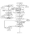
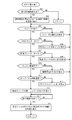
- the DPF 224 regeneration control first, if the key switch 61 is on (S101: YES), the detected values of the engine rotation sensor, the coolant temperature sensor, the differential pressure sensor and the DPF temperature sensor, and the intake throttle The opening degree of the member and the EGR valve member and the fuel injection amount by the common rail are read (S102). Next, if the accumulated drive time TI after executing the reset regeneration control or the non-work regeneration control in the past is less than the set time TI1 (for example, 50 hours) (S103: NO), the PM accumulation amount in the DPF 224 is estimated. (S104).
- the PM accumulation amount estimation is based on the P method based on the detection value of the differential pressure sensor and the exhaust gas flow map, the C method based on the detection value of the engine rotation sensor, the fuel injection amount, the PM emission map, and the exhaust gas flow map To do. If the PM accumulation amount is not less than a prescribed amount Ma (for example, 8 g / l) (S105: YES), assist regeneration control is executed (S106).
- a prescribed amount Ma for example, 8 g / l
- assist regeneration control is executed (S106).
- the PM accumulation amount in the DPF 224 is estimated based on the detected value of the engine rotation sensor, the fuel injection amount, the PM emission amount map, and the exhaust gas flow rate map (S107). If the PM accumulation amount is less than a prescribed amount Ma (for example, 6 g / l) (S108: YES), the assist regeneration control is terminated and the normal operation control is resumed. When the PM accumulation amount is equal to or greater than the prescribed amount Ma (S108: NO), when a predetermined time TI4 (for example, 10 minutes) has elapsed in this state (S109: YES), the step is a reset standby mode before reset regeneration control. The process proceeds to S201.
- a prescribed amount Ma for example, 6 g / l
- step S201 is a reset standby mode, and a reset regeneration request is executed.
- the reproduction lamp 912 and the reproduction switch 64 blink at a low speed (for example, 0.5 Hz), and the alarm buzzer sounds intermittently at a low speed (for example, 0.5 Hz).
- meter ECU 904 receives a command signal (regeneration control request output) for executing a reset regeneration request from engine ECU 271 through CAN communication bus.
- the reproduction lamp 912 blinks at a low speed
- the alarm buzzer sounds at a low speed.
- the reproduction switch 64 is blinked at a low speed.
- step S201 the meter ECU 904 switches the screen display of the liquid crystal panel 908 to the display based on the reset regeneration request information that prompts execution of reset regeneration control. It is also possible to display an operation instruction sign such as character data.
- the regeneration switch 64 is turned on for a predetermined time (for example, 3 seconds) (S202: YES)
- reset regeneration control is executed (S203).
- the regeneration lamp 912 and the regeneration switch 64 are turned on while the alarm buzzer is stopped.
- the screen display of the liquid crystal panel 908 may be changed from the reset reproduction request information to reset reproduction execution information based on a notification sign such as character data “reset reproduction in progress”.
- the PM accumulation amount in the exhaust filter 50 is estimated (S204). If the PM accumulation amount is less than a prescribed amount Mr (for example, 10 g / l) (S205: NO), reset regeneration is performed. If a predetermined time TI8 (for example, 30 minutes) has elapsed from the start of the control (S206: YES), the reset regeneration control is terminated and the normal operation control is resumed. At this time, in order to end the reset regeneration control, the regeneration lamp 912 and the regeneration switch 64 are turned off. When the reset reproduction execution information is displayed on the liquid crystal panel 908, the screen display of the liquid crystal panel 908 is changed from the reset reproduction execution information to the normal information.
- a prescribed amount Mr for example, 10 g / l
- a predetermined time TI8 for example, 30 minutes
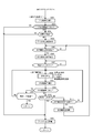
- the PM accumulation amount in the DPF 224 is estimated (S301). If the PM accumulation amount is less than a prescribed amount Mb (for example, 12 g / l) (S302: NO) and within a predetermined time TI9 (for example, 10 hours) (S303: NO), the first non-work regeneration request is executed. (S304). At this stage, the regeneration switch lamp 345 remains off, but the regeneration lamp 912 and the engine abnormality lamp 912 blink at high speed (for example, 1.0 Hz), and the alarm buzzer intermittently sounds at high speed (for example, 1.0 Hz). . Further, as shown in a flowchart of FIG.
- the screen display of the liquid crystal panel 908 may be switched to the display of the first non-work regeneration request index for notifying the execution of the non-work regeneration control.
- the first non-work regeneration request index is, for example, to alternately switch and display the character data “stop farm work” and the character data “park in a safe place”.
- the abnormality of the DPF 224 is notified (STEP 401).
- the engine abnormality lamp 912 blinks at high speed (for example, 1.0 Hz), and the alarm buzzer sounds at high speed (for example, 1.0 Hz).
- the regeneration lamp 912 and the regeneration switch 64 remain off. Further, the screen display of the liquid crystal panel 908 may be switched to a display of an abnormality warning sign that alternately switches between “exhaust filter abnormality” character data and “contact dealer” character data.
- step S305 After executing the first non-work regeneration request in step S304 described above, the process waits until a preset non-work regeneration transition condition (interlock release condition) is satisfied (S305).
- the non-work regeneration transition condition shown in step S305 is that the forward / reverse potentiometer is in the neutral position (neutral state of the forward / reverse switching lever 36), the parking brake switch is on (locked by the parking brake lever 43), and the PTO clutch switch 53 is off.
- the engine 5 has a low idle rotation speed (minimum rotation speed when there is no load) and a condition that the detected value of the cooling water temperature sensor is equal to or higher than a predetermined value (for example, 65 ° C.) (warming up of the engine 5 is completed). Yes.
- step S305 when the non-work regeneration transition condition (interlock release condition) is satisfied (YES), a second non-work regeneration request is executed (S306).
- the regeneration lamp 912 and the regeneration switch 64 blink at a low speed (for example, 0.5 Hz)
- the engine abnormality lamp 912 blinks at a high speed (for example, 1.0 Hz)
- the alarm buzzer switches to intermittent low-speed sound (for example, 0.5 Hz).
- the screen display of the liquid crystal panel 908 may be changed to the display based on the second non-work regeneration request information that prompts execution of the non-work regeneration control. That is, on the liquid crystal panel 908, as in the display by the reset reproduction request information in step S201, an operation instruction sign such as character data “Please press and hold the reproduction switch” is displayed.
- non-work regeneration control is executed (S308). That is, the meter ECU 904 notifies the engine ECU 271 that the operator has turned on the regeneration switch 64, whereby the engine controller 271 executes non-work regeneration control. At this stage, the regeneration lamp 912, the regeneration switch 64, and the engine abnormality lamp 912 are turned on, and the alarm buzzer is stopped. Thus, since the operator recognizes that the non-work regeneration control is being executed, it is possible to prevent an operator from operating erroneously when the non-work regeneration control is executed.
- the screen display of the liquid crystal panel 908 may be changed from the second non-work reproduction request information to the non-work reproduction execution information.
- the non-working regeneration notification sign for alternately switching the character data “regenerating exhaust filter” and the character data “waiting for regeneration” is displayed on the liquid crystal panel 908. That is, by configuring the display to prohibit the operation of this apparatus until the reproduction control is completed, erroneous operation by the operator can be prevented in advance.
- the PM accumulation amount in the DPR 224 is estimated (S309). If the PM accumulation amount is less than a prescribed amount Ms (for example, 8 g / l) (S310: YES) and a predetermined time TI11 (for example, 30 minutes) has elapsed from the start of non-work regeneration control (S311: YES), non-work The regeneration control is terminated and the normal operation control is resumed.
- Ms for example, 8 g / l
- TI11 for example, 30 minutes
- step S401 for notifying the abnormality of the exhaust filter 50.
- the non-work regeneration control is performed. After the interruption (S314), the process proceeds to step S304 to execute the first non-work regeneration request.
- the non-work regeneration control may be interrupted when 64 is pressed. Thereby, the non-work regeneration control of the DPF 224 can be interrupted without performing troublesome operations such as the operation of stopping the engine 5 and interrupting the non-work regeneration control of the DPF 224.
- the meter ECU 904 receives the first non-work regeneration request from the engine ECU 271 in the above step S304 (S501: YES), the character data “stop farm work section” and “park in a safe place” are displayed on the liquid crystal panel 908.
- a first non-work regeneration request index for alternately switching and displaying character data is displayed (S502).
- the meter ECU 904 confirms whether or not the forward / reverse switching lever 36 is in a neutral state (S503).
- the meter ECU 904 confirms whether or not the PTO clutch switch 53 is in an OFF state based on a signal from the PTO clutch switch 53 (S505).
- the PTO clutch switch 53 is in the on state (S505: NO)
- an operation index based on the character data “turn off the PTO switch” is displayed on the liquid crystal panel 908 to prompt the operator to turn off the PTO clutch switch 53. (S506).
- the meter ECU 904 confirms whether or not the parking brake lever 43 is locked (S507).
- the parking brake switch is in the OFF state (S507: NO)
- an operation index based on the character data “apply the parking brake” is displayed on the liquid crystal panel 908 to prompt the operator to lock the parking brake lever 43. (S508).
- the meter ECU 904 communicates with the engine ECU 271 to check whether or not the warm-up operation of the engine 5 has been completed based on the signal from the cooling water temperature sensor (S509).
- a predetermined value for example, 65 ° C.
- S509: NO the characters “perform warming operation” on the liquid crystal panel 908 to prompt the operator to complete the warming operation of the engine 5.
- An operation index based on the data is displayed (S510).
- the meter ECU 904 communicates with the engine ECU 271 to check whether or not the engine 5 is at a low idle rotation speed based on a signal from the engine rotation sensor (S511).
- an operation index based on the character data of “idling” is displayed on the liquid crystal panel 908 to prompt the operator to operate the engine 5 at the low idle. It is displayed (S512).
- the non-working regeneration transition condition is satisfied. Therefore, the second non-working regeneration request in step S306 is executed, and the “reproduction” is displayed on the liquid crystal panel 908.
- An operation instruction sign with character data “Please press and hold the switch” is displayed (S513).
- step S307 it is determined whether or not a long press operation on the reproduction switch 64 has been performed (S514). At this time, if the regeneration switch 64 is turned on for a predetermined time (S514: YES), the liquid crystal panel 908 switches between the character data “regenerating exhaust filter” and the character data “waiting for completion of regeneration” alternately. A work regeneration notification sign is displayed (S515).
Landscapes
- Engineering & Computer Science (AREA)
- Mechanical Engineering (AREA)
- Chemical & Material Sciences (AREA)
- Combustion & Propulsion (AREA)
- Transportation (AREA)
- Instrument Panels (AREA)
Abstract
DPF再生スイッチ、作業用スイッチ、ワンタッチ自動スイッチなど複数のスイッチを操縦座席正面に集中的に設けたものでありながら、各スイッチについて、オペレータが容易に視認できるようにした作業車両を提供することを目的としている。走行機体2に装設させる操縦座席8が内設されるキャビン7を備えた作業車両であって、DPF再生スイッチ64、作業用スイッチ65、ワンタッチ自動スイッチ65を備える。操縦ハンドル9基部のステアリングコラム32上面に前記DPF再生スイッチ64を設けて、直進作業姿勢のときにオペレータの視界に前記DPF再生スイッチ64が配置される。
Description
本願発明は、耕耘作業機または播種作業機などの対地作業機を牽引する農作業用のトラクタまたは土木作業用のホイルローダなどの作業車両に関するものである。
トラクタやホイルローダ等の作業車両においては、走行機体を操向操作するための操縦ハンドルや、走行機体の走行状態を設定調節するための複数のレバー部材等が、操作性を考慮して操縦座席の周囲に配置されている。例えば、農作業用のトラクタでは、複数のレバー部材として、主変速レバー、副変速レバー、前後進切換レバー、並びにPTO変速レバー等を有している(特許文献1参照)。主変速レバーは走行機体の車速を変更操作するものであり、副変速レバーは変速機の変速出力を所定範囲に設定保持するものである。前後進切換レバーは走行機体の進行方向を前進と後進とに切換操作するものであり、PTO変速レバーは作業機への出力(PTO駆動力)を変速操作するものである。
また、上記作業車両は、操縦ハンドルをはじめとする各種操作機器と操縦座席とを内装したキャビンを走行機体上に搭載している(特許文献1及び特許文献2参照)。このキャビン搭載型の作業車両は、作業者(操縦者)の視認性を確保するために、フロントガラスの汚れを除去するワイパーを設けている(特許文献2参照)。
ところで、この種の作業車両のように、フロントガラスの外側にワイパを設ける構造では、ワイパを駆動するワイパモータを含むワイパ駆動機構が必要であり、ワイパモータの支持部を簡単に確保できない等の問題があった。また、従来では、フロントガラスを3分割形成する構造であるため、接合作業などの組付け作業が煩雑であるだけでなく、接合部分が死角となり、前方の視認性を阻害している。
そして、この種の作業車両においては、DPF再生スイッチ、作業用スイッチ、ワンタッチ自動スイッチなど複数のスイッチを操縦座席正面に集中的に設けているため、操縦ハンドルや操作レバーなどに隠れて、オペレータが容易に視認できないという問題があった。また、この種の作業車両において、オペレータの運転姿勢にあわせて、操縦ハンドルの姿勢を調節するチルトレバー、テレスコレバーを設ける構造のものがあるが、チルトレバー、テレスコレバーを誤操作すると、操縦ハンドルの姿勢がオペレータの想定外の姿勢になる等の問題があった。
本願発明は、上記のような現状を検討して改善を施したトラクタを提供することを技術的課題としている。
本願発明の作業車両は、走行機体上に設けた操縦座席前方にステアリングコラムを配置しており、該ステアリングコラム上面から上向きに突出したハンドル軸の上端側に平面視略丸型の操縦ハンドルを設けた作業車両において、前記操縦ハンドルを、前記ハンドル軸に軸支されたスポークと該スポークの外側に配置したステアリングホイールとで構成しており、前記ステアリングコラム上面のうち、前記操縦ハンドル軸を中心とした左右対称の前記ステアリングコラム上面であって、直進走行位置の前記操縦ハンドルにおける前記スポークと前記ステアリングホイールで囲まれた領域に対応する位置に、複数のスイッチを配置したものである。
このような作業車両において、前記ステアリングコラムを埋設するように立設したダッシュボードにメータパネルを固定させており、前記操縦ハンドルの前記スポークをY字に設置するとともに、直進走行位置の前記操縦ハンドルにおける前記スポークの間に前記メータパネルを位置させて、直進作業姿勢のときにオペレータの視界に前記メータパネルを配置させるものとしてもよい。
そして、前記ダッシュボードは、前記メータパネルを固定する内側ボードと、内側ボード上側から覆うようにして固定する外側カバーとで構成されており、前記内側ボードは、前記メータパネル表示面を配置する開口部と、前記開口部外周部分を隆起させた側壁を備え、前記メータパネル表示面外側を前記側壁で囲んだ形状であるものとしてもよい。
また、前記ステアリングコラム上面にDPF再生スイッチと作業用スイッチとワンタッチ自動スイッチを設け、ブレーキペダル上方のステアリングコラム一側上面に前記DPF再生スイッチを設置すると共に、走行機体の前後中心線上に配置される前記操縦ハンドルのスポークを挟んで、前記作業用スイッチとワンタッチ自動スイッチを設置したものとしてもよい。
また、前記操縦ハンドルは、前記ハンドル軸に軸支されるハンドル本体と、該ハンドル本体中心部分のハブの上面を覆うハブカバーと、該ハブカバーの上面を覆うキャップとで構成されており、前記キャップにスイッチの第1接点を設ける一方、前記ハブカバーに前記スイッチの第2接点を設けており、前記ハンドル本体の軸芯位置に設けて前記ハンドル軸に嵌合されるボスに、前記第1接点を電気的に接続する一方、前記ハンドル本体のハブ下面に設けて前記ボスと絶縁されているスリップリングに、前記第2接点を電気的に接続したものとしてもよい。
また、上記作業車両において、フロントガラスの外側に設けるワイパと、前記ワイパを駆動するワイパ駆動機構を備える作業車両であって、操縦ハンドルが配置されるステアリングコラムの前面側にエアカットプレートを備える構造であって、前記エアカットプレートに前記ワイパ駆動機構を取付けたものとすることで、前記エアカットプレート上端部のメータ表示部の内方にワイパ駆動機構をコンパクトに支持できるものでありながら、前記ワイパとワイパ駆動機構の組立作業性を向上できる。
そして、前記エアカットプレートの後面に前記ワイパ駆動機構を固着し、前記エアカットプレートの前面側に前記フロントガラスを張設し、前記エアカットプレートとフロントガラスに前記ワイパ駆動機構の駆動軸を貫通させたものとすることで、前記フロントガラスを3分割形成する構造に比べ、前記フロントガラスの接合作業を省略でき、前記フロントガラスの組付け作業を簡略化できるとともに、意匠性を向上できる。
また、前記フロントガラスの前面のうち、前記エアカットプレートに対向するフロントガラス前面に、板金枠によりお遮音材を張設し、前記遮音材にワイパ駆動機構の駆動軸を貫通させたものとすることで、エアカットプレート(キャビン)側にエンジン騒音が伝達されるのを防止できる。ワイパ駆動機構の駆動軸取付け部の防水構造を簡略化できる。
また、上記作業車両において、操縦ハンドルの姿勢を調節するチルトレバーとテレスコレバーを備える作業車両であって、前記操縦ハンドルが配置されるステアリングコラムの左右に、前記チルトレバーとテレスコレバーを振分けて配置したものとすることで、前記チルトレバーまたはテレスコレバーの誤操作を低減でき、操縦ハンドルの姿勢がオペレータの想定外の姿勢に変更されるのを容易に防止できる。
そして、前記ステアリングコラムの左側に前記チルトレバーを設置し、前記ステアリングコラムの右側に前記テレスコレバーを設置したものとすることで、ペレータが左手で前記チルトレバーを握り、右手で前記操縦ハンドルを握り、テレスコ調節操作よりも頻度が高い前記操縦ハンドルのチルト調節操作性を向上できる。
更に、前記操縦ハンドルの姿勢調節と連動して前記ステアリングコラムの姿勢が変更されるように構成したものとすることで、前記ステアリングコラムの上面側に配置される表示ランプまたはスイッチ支持位置が、前記操縦ハンドルと連動して位置調節されるから、座乗したオペレータの視界に表示ランプまたはスイッチを支持できる。
本願発明によれば、操縦ハンドルの形状にあわせて、ステアリングコラム上にスイッチを配置しているので、座乗したオペレータにてスイッチを容易に視認して判別でき、作業中や走行中での誤操作を防止できる。また、操縦ハンドルの形状に合わせてメータパネルの配置位置を設定したことにより、オペレータは直視しながら容易に作業車両の状態を情報入手することができるだけでなく、作業車両の状態に合わせて的確にスイッチを選択して操作できる。
本願発明によれば、ダッシュボードの最背面よりも奥まった位置に、メータパネルの表示面を配置できるため、操縦座席をキャビン内に配置する場合に、ガラスで構成されるサイドドア等への映り込みを防止できる。そのため、メータパネル表示面の発光に基づく映り込みがなく、走行時や作業時におけるオペレータの視界の妨げを防止でき、快適に運転できる。
本願発明によれば、前記DPF再生スイッチが、操縦ハンドルまたは操作レバーなどに隠れることなく、座乗したオペレータにて、前記DPF再生スイッチの位置及び点灯表示状態を容易に視認できる。また、座乗したオペレータにて、前記作業用スイッチとワンタッチ自動スイッチの位置を容易に視認でき、誤操作を低減できる。
本願発明によれば、回転部品である操縦ハンドルにスイッチを容易に組み込むことができるとともに、操縦ハンドルの組立作業やメンテナンス作業における作業性を向上できる。スイッチをホーンスイッチとすることで、操縦ハンドルでホーンによる警報動作を操作できるため、オペレータの操作性を向上できる。
以下に、本願発明を具体化した実施形態について、農作業用トラクタを図面に基づき説明する。図1~図8に示す如く、トラクタ1の走行機体2は、走行部としての左右一対の前車輪3と同じく左右一対の後車輪4とで支持されている。左右一対の後車輪4が後方走行部に相当するものである。走行機体2の前部にディーゼルエンジン5(以下、単にエンジンという)を搭載し、後車輪4または前車輪3をエンジン5で駆動することによって、トラクタ1が前後進走行するように構成されている。エンジン5はボンネット6にて覆われている。走行機体2の上面にはキャビン7が設置される。該キャビン7の内部には、操縦座席8と、前車輪3を操向操作する操縦ハンドル9とが配置されている。キャビン7の左右外側には、オペレータが乗降するステップ10が設けられている。エンジン5に燃料を供給する燃料タンク11がキャビン7底部の下側に設けられている。
走行機体2は、前バンパー12及び前車軸ケース13を有するエンジンフレーム14と、エンジンフレーム14の後部に着脱自在に固定した左右の機体フレーム15とにより構成されている。前車軸ケース13の左右両端側から外向きに、前車軸16を回転可能に突出させている。前車軸ケース13の左右両端側に前車軸16を介して前車輪3を取り付けている。機体フレーム15の後部には、エンジン5からの回転動力を適宜変速して前後四輪3,3,4,4に伝達するためのミッションケース17を連結している。左右の機体フレーム15及びミッションケース17の下面側には、左右外向きに張り出した底面視矩形枠板状のタンクフレーム18をボルト締結している。実施形態の燃料タンク11は左右2つに分かれている。タンクフレーム18の左右張り出し部の上面側に、左右の燃料タンク11を振り分けて搭載している。ミッションケース17の左右外側面には、左右の後車軸ケース19を外向きに突出するように装着している。左右の後車軸ケース19には左右の後車軸20を回転可能に内挿している。ミッションケース17に後車軸20を介して後車輪4を取り付けている。左右の後車輪4の上方は左右のリヤフェンダー21によって覆われている。
ミッションケース17の後部には、例えばロータリ耕耘機などの対地作業機(図示省略)を昇降動させる油圧式昇降機構22を着脱可能に取付けている。前記対地作業機は、左右一対のロワーリンク23及びトップリンク24からなる3点リンク機構111を介してミッションケース17の後部に連結される。ミッションケース17の後側面には、ロータリ耕耘機等の対地作業機にPTO駆動力を伝達するためのPTO軸25を後向きに突設している。
エンジン5の後側面から後向きに突設するエンジン5の出力軸(ピストンロッド)には、フライホイル26(図4~図6、図10及び図11参照)を連結している。両端に自在軸継手を有する動力伝達軸29を介して、フライホイル26から後ろ向きに突出した主動軸27と、ミッションケース17前面側から前向きに突出した主変速入力軸28とを連結している(図4~図6参照)。図13に示す如く、ミッションケース17の内部には、油圧無段変速機500、前後進切換機構501、走行変速ギヤ機構502,503,504及び後輪用差動ギヤ機構506などを配置している。エンジン5の回転動力は、主動軸27及び動力伝達軸29を経由してミッションケース17の主変速入力軸28に伝達され、油圧無段変速機500及び走行変速ギヤ機構によって変速され、当該変速動力が後輪用差動ギヤ機構506を介して左右の後車輪4に伝達されるように構成している。
ミッションケース17の前面下部から前向きに突出した前車輪出力軸30には、前車輪駆動軸31を介して、前輪用差動ギヤ機構507を内蔵する前車軸ケース13から後向きに突出した前車輪伝達軸508を連結している。ミッションケース17内の油圧無段変速機500及び走行変速ギヤ機構(二駆四駆切換機構504)による変速動力は、前車輪出力軸30、前車輪駆動軸31及び前車輪伝達軸508から前車軸ケース13内の前輪用差動ギヤ機構507を経由して、左右の前車輪3に伝達されるように構成している。
次に、図3、図7及び図8等を参照しながら、キャビン7内部の構造を説明する。キャビン7内における操縦座席8の前方にステアリングコラム32を配置している。ステアリングコラム32は、キャビン7内部の前面側に配置したダッシュボード33の背面側に立設している。ステアリングコラム32上面から上向きに突出したハンドル軸の上端側に、平面視略丸型の操縦ハンドル9を取付けている。
ステアリングコラム32の右側下方側には、走行機体2を制動操作するための左右一対のブレーキペダル35を配置している。ステアリングコラム32の左側上方側には、走行機体2の進行方向を前進と後進とに切り換え操作するための前後進切換レバー36(リバーサレバー)を配置している。ステアリングコラム32の左側下方側には、油圧無段変速機500の出力(前進低速油圧クラッチ537、前進高速油圧クラッチ539、後進油圧クラッチ541)を遮断操作するためのクラッチペダル37を配置している。なお、クラッチペダル37の足踏み操作にてマスター制御電磁弁635がオン操作され、油圧無段変速機500の前進出力または後進出力が切断される(図14参照)。
ステアリングコラム32の左側で前後進切換レバー36の下方には、前後進切換レバー36に沿って延びる誤操作防止体38(リバーサガード)を配置している。接触防止具である誤操作防止体38を前後進切換レバー36よりも外側方に突出させることによって、トラクタ1に乗降する際に、オペレータが前後進切換レバー36に不用意に接触するのを防止している。ダッシュボード33の背面上部側には、液晶パネルを内蔵した操作表示盤39を設けている。
キャビン7内にある操縦座席8前方の床板40においてステアリングコラム32の右側には、エンジン5の回転速度または車速などを制御するアクセルペダル41を配置している。なお、床板40上面の略全体は平坦面に形成している。操縦座席8を挟んで左右両側には左右のサイドコラム42を配置している。操縦座席8と左サイドコラム42との間には、左右の後車輪4を制動状態に維持する駐車ブレーキレバー43と、トラクタ1の前進走行速度(車速)を強制的に大幅に低減させる超低速レバー44(クリープ作業レバー)と、ミッションケース17内の走行副変速ギヤ機構503の出力範囲を切換える副変速レバー45と、PTO軸25の駆動速度を切換操作するPTO変速レバー46を配置している。操縦座席8の下方には、左右の後車輪4の差動駆動をオンオフするためのデフロックペダル47を配置している。操縦座席8の後方左側には、PTO軸25を逆転駆動させる操作を実行する逆転PTOレバー48を配置している(図10参照)。
操縦座席8と右サイドコラム42との間には、操縦座席8に着座したオペレータの腕や肘を載せるためのアームレスト49を設けている。アームレスト49は、トラクタ1の走行速度を増減速させる主変速レバー50と、ロータリ耕耘機などの対地作業機の高さ位置を手動で変更調節するダイヤル式の作業部ポジションダイヤル51(昇降ダイヤル)とを備えている。なお、アームレスト49は、後端下部を支点として複数段階に跳ね上げ回動可能な構成になっている。
右サイドコラム42には、前側から順に、エンジン5の回転速度を設定保持するスロットルレバー52と、PTO軸25からロータリ耕耘機等の作業機への動力伝達を継断操作するPTOクラッチスイッチ53と、ミッションケース17の上面側に配置する油圧外部取出バルブ430(図14参照)を切換操作するための複数の油圧操作レバー54(SCVレバー)とを配置している。ここで、油圧外部取出バルブ430は、トラクタ1に後付けされるフロントローダ等の作業機の油圧機器に作動油を供給制御するためのものである。実施形態では、油圧外部取出バルブの数(4連)に合わせて、油圧操作レバー54を4つ配置している。
さらに、図9~図12などに示す如く、キャビン7の前側を支持する左右の前部支持台96と、キャビン7の後部を支持する左右の後部支持台97を備える。左右の機体フレーム15の機外側面のうち前後中間部に前部支持台96をボルト締結させ、前部支持台96の上面側に防振ゴム体98を介してキャビン7の前側底部を防振支持すると共に、左右方向に水平に延設させる左右の後車軸ケース19の上面のうち左右幅中間部に後部支持台97をボルト締結させ、後部支持台97の上面側に防振ゴム体99を介してキャビン7の後側底部を防振支持している。即ち、ディーゼルエンジン5とキャビン7は、走行機体2(一体的に連結されたエンジンフレーム14と機体フレーム15と後車軸ケース19)に、複数の前記防振ゴム体を介して防振支持される。また、図4及び図5などに示す如く、後車軸ケース19の上面側に後部支持台97を配置し、後車軸ケース19の下面側に振れ止めブラケット101を配置し、後部支持台97と振れ止めブラケット101をボルト締結すると共に、前後方向に延設したロワーリンク23の中間部と振れ止めブラケット101とに、伸縮調節可能なターンバックル付き振れ止めロッド体103の両端部を連結し、ロワーリンク23の左右方向の揺振を防止している。
次に、図4~図8などを参照して、ボンネット6下のディーゼルエンジン5とエンジンルーム構造について説明する。ディーゼルエンジン5は、エンジン出力軸とピストンとを内蔵するシリンダブロック上にシリンダヘッドを搭載しており、ディーゼルエンジン5(シリンダヘッド)右側面には、エアクリーナ221にターボ過給機211を介して接続させる吸気マニホールド203と、排気マニホールド204からの排気ガスの一部を再循環させるEGR装置210を配置し、排気マニホールド204に排出された排気ガスの一部が、吸気マニホールド203に還流することによって、高負荷運転時の最高燃焼温度が低下し、ディーゼルエンジン5からのNOx(窒素酸化物)の排出量が低減するように構成している。一方、ディーゼルエンジン5(シリンダヘッド)左側面に、テールパイプ229に接続させる排気マニホールド204と、ターボ過給機211を配置する。即ち、エンジン5においてエンジン出力軸に沿う左右側面に、吸気マニホールド203と排気マニホールド204とを振分け配置する。ディーゼルエンジン5(シリンダブロック)前面側に冷却ファン206を配置する。
加えて、図4~図8などに示す如く、ディーゼルエンジン5は、ディーゼルエンジン5の上面側(排気マニホールド204上方)に配置する連続再生式の排気ガス浄化装置224(DPF)を備え、排気ガス浄化装置224の排気側にテールパイプ229を接続している。排気ガス浄化装置224によって、エンジン5からテールパイプ229を介して機外に排出される排気ガス中の粒子状物質(PM)が除去されると共に、排気ガス中の一酸化炭素(CO)や炭化水素(HC)が低減されるように構成している。
さらに、図1~図3などに示す如く、ボンネット6は、前部下側にフロントグリル231を有し、エンジンルーム200の上面側と前面側を覆う。ボンネット6の左右下側に、多孔板で形成した側部エンジンカバー232を配置して、エンジンルーム200左右側方を覆っている。すなわち、ボンネット6及びエンジンカバー232によって、ディーゼルエンジン5の前方、上方及び左右を覆っている。
また、図4~図8に示すように、ファンシュラウド234を背面側に取り付けたラジエータ235を、エンジン5の前面側に位置するようにエンジンフレーム14上に立設している。ファンシュラウド234は冷却ファン206の外周側を囲っていて、ラジエータ235と冷却ファン206とを連通させている。ラジエータ235前面の上方位置にエアクリーナ221を配置している。なお、ラジエータ235前面側には、上記のインタークーラ他、オイルクーラや燃料クーラなどが設置される。更に、エンジン制御装置(エンジンECU)271が、ラジエータ235等の熱交換機の前方位置に配置されている。エンジンECU271は、エンジン5の各センサからのセンサ信号を受けるとともにエンジン5の駆動を制御する。エンジン制御装置271の長手方向を走行機体2の前後方向(エンジンフレーム14の長手方向)に沿わせてフレーム底板233に立設させている。
一方、図9~図12などに示す如く、左右一対の機体フレーム15は、支持用梁フレーム236によって連結されている。支持用梁フレーム236は、左右の機体フレーム15それぞれとボルト締結して、左右の機体フレーム15の前端部(エンジン5後面側)に架設しており、防振ゴム体を有する後部機関脚体237を介して、支持用梁フレーム236上面にディーゼルエンジン5の後部を連結する。なお、図1、図2、図4、図5、図11及び図12に示すように、左右一対のエンジンフレーム14の中途部に、防振ゴム体を有する左右の前部機関脚体238を介して、ディーゼルエンジン5前部の左右側面を連結している。即ち、エンジンフレーム14にディーゼルエンジン5前側を防振支持させると共に、左右一対の機体フレーム15の前端側に支持用梁フレーム236を介してディーゼルエンジン5の後部を防振支持させている。
次に、図4~図12を参照して、ミッションケース17、油圧式昇降機構22及び3点リンク機構111の取付け構造について説明する。前記ミッションケース17は、主変速入力軸28等を有する前部変速ケース112と、後車軸ケース19などを有する後部変速ケース113と、前部変速ケース112の後側に後部変速ケース113の前側を連結させる中間ケース114を備えている。中間ケース114の左右側面に左右の上下機体連結軸体115,116を介して左右の機体フレーム15の後端部を連結する。即ち、2本の上機体連結軸体115と、2本の下機体連結軸体116にて、中間ケース114の左右両側面に左右の機体フレーム15の後端部を連結させ、機体フレーム15とミッションケース17を一体的に連設して、走行機体2の後部を構成すると共に、左右の機体フレーム15の間に前部変速ケース112または動力伝達軸29などを配置して、前部変速ケース112などを保護するように構成している。左右の後車軸ケース19は、後部変速ケース113の左右両側に外向きに突出するように取り付けている。実施形態では、中間ケース114及び後部変速ケース113を高剛性の鋳鉄製にする一方、前部変速ケース112を軽量かつ加工性良好なアルミダイキャスト製にしている。
上記の構成によると、ミッションケース17を、前部変速ケース112、中間ケース114及び後部ケース113の三者に分割して構成しているから、各ケース112~114に軸やギヤ等の部品を予め組み込んでから、前部変速ケース112、中間ケース114及び後部変速ケース113の三者を組み立てできる。従って、ミッションケース17の組み立てを正確に且つ能率よく行える。
また、左右の後車軸ケース19を後部変速ケース113の左右両側に取付け、走行機体2を構成する左右の機体フレーム15に、前部変速ケース112と後部変速ケース113とをつなぐ高剛性構造の中間ケース114を連結しているから、例えば中間ケース114及び後部変速ケース113を機体フレーム15に取付けた状態で、前部変速ケース112だけを取外して、油圧無段変速機(図示省略)などが内設された前部変速ケース112内部の軸やギヤの交換などのメンテナンスまたは修理作業を実行できる。従って、ミッションケース17全体をトラクタ1から取外す分解作業の頻度を格段に低くでき、メンテナンス時や修理時の作業性の向上を図れる。
更に、中間ケース114及び後部変速ケース113を鋳鉄製にする一方、前部変速ケース112をアルミダイキャスト製にしているから、機体フレーム15に連結される中間ケース114と、左右の後車軸ケース19が連結される後部変速ケース113とを、走行機体2を構成する強度メンバーとして高剛性に構成できる。その上で強度メンバーではない前部変速ケース112を軽量化できる。従って、走行機体2の剛性を十分に確保しつつ、ミッションケース17全体としての軽量化を図れる。
一方、図4~図12に示すように、油圧式昇降機構22は、作業部ポジションダイヤル51等の操作にて作動制御する左右の油圧リフトシリンダ117と、ミッションケース17のうち後部変速ケース113上面側に設ける開閉可能な上面蓋体118にリフト支点軸119を介して基端側を回動可能に軸支する左右のリフトアーム120と、左右のロワーリンク23に左右のリフトアーム120を連結させる左右のリフトロッド121を有している。右のリフトロッド121の一部を油圧制御用の水平シリンダ122にて形成し、右のリフトロッド121の長さを水平シリンダ122にて伸縮調節可能に構成している。
なお、図7、図8及び図10などに示す如く、上面蓋体118の背面側にトップリンクヒンジ123を固着し、トップリンクヒンジ123にヒンジピンを介してトップリンク24を連結する。トップリンク24と左右のロワーリンク23に対地作業機を支持した状態下で、水平シリンダ122のピストンを伸縮させて、右のリフトロッド121の長さを変更した場合、前記対地作業機の左右傾斜角度が変化するように構成している。
次に、図1及び図2等を参照しながら、キャビン7の詳細構造について説明する。走行機体2上にある操縦座席8を覆うキャビン7は骨組を構成するキャビンフレーム300を備えている。キャビンフレーム300は、操縦座席8の前方に位置する左右一対の前支柱301と、操縦座席8の後方に位置する左右一対の後支柱302と、前支柱301同士の上端部間を連結する前梁部材303と、後支柱302同士の上端部間を連結する後梁部材304と、前後に並ぶ前支柱301と後支柱302との上端部間を連結する左右の側梁部材305とを備えた略箱枠状のものである。キャビンフレーム301の上端側、すなわち前梁部材303、後梁部材304及び左右の側梁部材305で構成した矩形枠上には屋根体306を着脱可能に取付けている。
なお、前支柱301と後支柱302の下端側には、前後に延びる左右の底フレーム311の長手方向各端部を連結している。左右の底フレーム311上面側に床板40を張設させ、床板40前端側にダッシュボード33を立設させ、ダッシュボード33の後面側にステアリングコラム32を介して操縦ハンドル9を装設している。床板40の前部上面側にブレーキペダル35などが配設されると共に、床板40の後部上面側に操縦座席8が取付けられている。
キャビンフレーム300の前面側、すなわち左右の前支柱301、前梁部材303及び床板40前端部で囲まれるキャビン7前部の領域には、フロントウィンドガラス321を配置している。キャビンフレーム300の後面側、すなわち左右の後支柱302と後梁部材304で囲まれるキャビン7後側上部の領域には、リヤウィンドガラス322を配置している。キャビンフレーム300の左右側面側、すなわち前後に並ぶ前支柱301及び後支柱302で囲まれるキャビン7側部の領域には、透明なガラスで構成した左右のサイドドア323を配置している。各サイドドア323は、対応する後支柱302に上下一対のヒンジ324を介して開閉可能に取付けている。
フロントウィンドガラス321、リヤウィンドガラス322及び左右のサイドドア323の配置構造から明らかなように、各支柱301,302及び各梁部材303,304,305は、キャビン7(キャビンフレーム300)の側辺部に位置している。即ち、キャビンフレーム300の前後左右側面に窓を広く取ることが可能になっている。実施形態では、キャビンフレーム300の前後左右側面に、フロントウィンドガラス321、リヤウィンドガラス322、透明なガラス製の左右のサイドドア323を配置している。その結果、オペレータの前後左右の視界を広く確保できるものでありながら、キャビンフレーム300の剛性も確保できる。
図13~図19等に示すように、ダッシュボード33の前側は、ボンネット6下のエンジン5等からの熱を遮蔽するための遮熱板(エアカットプレート)901で覆われる。また、フロントウィンドガラス321が1枚のガラス板で構成されており、フロントウィンドガラス321背面にエアカットプレート901を連結する。そして、フロントウィンドガラス321前面には、遮熱性と遮音性とを兼ね備えたウレタン材902を張設している。ウレタン材902外周を囲う板金枠903とエアカットプレート901とを、フロントウィンドガラス321介在させて締結させることで、フロントウィンドガラス321の前後に、ウレタン材902及びエアカットプレート901を固定させる。
ダッシュボード33は、フロントウィンドガラス321後方を覆ってワイパ駆動機構422を内装している。ワイパ駆動機構422は、フロントウィンドガラス321に軸支されているワイパ421への回転動力を生成する駆動モータと、駆動モータの回転動力をワイパ421に伝達するギヤ機構とで構成されている。ワイパ駆動機構422における駆動モータが回転することで、ギヤ機構を介して駆動モータの回転がワイパ421に伝達し、ワイパ421がフロントウィンドガラス321表面に沿って回動する。
ワイパ駆動機構422は、エアカットプレート901と連結して固定されている。すなわち、エアカットプレート901の後面にワイパ駆動機構422を固着し、エアカットプレート901の前面側にフロントウィンドガラス321を張設している。そして、フロントウィンドガラス321に、ワイパ駆動機構422の駆動軸422aを貫通させている。ワイパ駆動機構422の駆動軸422aがワイパ421を枢支することで、ワイパ駆動機構422によりワイパ421が回動する。
更に、フロントウィンドガラス321前面のうちエアカットプレート901に対向する領域に、シール材を介して、板金枠で囲われたウレタン材(遮音材)902を張設している。そして、ウレタン材902に、ワイパ駆動機構422の駆動軸422aを貫通させている。フロントウィンドガラス321前面にウレタン材902を張設することで、エアカットプレート901側にエンジン5からの騒音が伝達されるのを防止できる。
エアカットプレート901の後面には、ワイパ駆動機構422とともに、メータ制御装置(メータECU)904やアンテナ905が固着されている。エアカットプレート901に、ワイパ駆動機構422、メータECU904、及びアンテナ905を取り付けることによって、1つのユニットとして構成できるため、ダッシュボード33内側への各部品の組付け作業を簡略化できる。
ダッシュボード33は、インナーボード(内側ボード)33aと、アウターボード(外側カバー)33bとで構成されている。インナーボード33aの外周縁をエアカットプレート901の外周縁に連結して、インナーボード33aをエアカットプレート901背面に固定する。そして、インナーボード33a上部を覆うように、アウターボード33bをインナーボード33a上側から嵌めて、ダッシュボード33を形成する。インナーボード33aの中央上側に開口部33cが設けられており、開口部33cにメータパネル905表示面が収まるように、インナーボード33a前面にメータパネル906を固定させる。
また、インナーボード33aは、開口部33c外周部分を隆起させた形状を有することで、メータパネル906の表示部外側を側壁33dで囲んだ状態とする。これにより、ダッシュボード33の最背面よりも奥まった位置に、メータパネル906の表示面を配置できるため、キャビン7のサイドドア323等への映り込みを防止できる。そのため、メータパネル906表示面の発光に基づく映り込みがなく、走行時や作業時におけるオペレータの視界の妨げを防止できる。
メータパネル906は、操縦ハンドル9の前方下側となる位置で、操縦座席8に着座したオペレータに対面するように、そのパネル表面を後方からやや上方に傾けた状態で配置されている。又、メータパネル906の外縁は、内側から外側に向けて隆起させたインナーボード33aの側壁33dで覆われている。インナーボード33aは、メータパネル906外周となる位置に、例えば、パーキングスイッチやワイパスイッチなどの複数のスイッチ部材907を配置している。また、キースイッチ61は、鍵穴に差し込んだ所定の鍵にて回転操作可能なロータリ式スイッチであり、ダッシュボード33における操縦ハンドル9の右側位置に取り付けられている。
メータパネル906は、運転操作表示装置として、その中央表示領域に、文字表示などを行う液晶パネル908を配置しており、液晶パネル908外周にエンジン5の回転数を指針で示すエンジン回転計909を設けている。また、メータパネル906は、エンジン回転計909の左側に、燃料残量を指針で示す燃料計910を配置し、エンジン回転計910の右側に、エンジン5の冷却水温を指針で示す水温計911を配置している。
また、メータパネル906は、エンジン回転計909の左右外側(中央表示領域の外側)の表示領域にLED等による複数の表示ランプ912,913を配置している。エンジン回転計909の左に配置された表示ランプ912は、例えば、走行系に関する警告灯や表示灯として作用する。一方、エンジン回転計909の右に配置された表示ランプ913は、作業系に関する警告灯や表示灯として作用する。また、左右の表示ランプ912,913のうち、一方を軽度の故障による警告灯として作用させ、他方を重度の故障による警告灯として作用させる。また、左側の表示ランプ912を走行系に関する警告灯又は表示灯として作用させる場合に、表示ランプ912の一つを、排気ガス浄化装置224の再生処理状態を示す再生ランプに割り当てる。
図17~図22に示す如く、ステアリングコラム32は、インナーボード33bで周囲が囲まれるように設置されており、ダッシュボード33の背面側に埋設するような状態で立設している。ステアリングコラム32内に縦長のステアリング軸738を軸支している。ステアリング軸738は、ハンドル軸921上端をステアリングコラム32上面から上向きに突出しし、ハンドル軸921の上端側に平面視略丸型の操縦ハンドル9を取り付けている。ハンドル軸921の下端側には、自在継手922を介して縦長の連結軸740の先端側を連結している。連結軸740の基端側には、自在継手741を介して、ボード支持板(エアカットプレート)901の下部側に支持させたパワーステアリング油圧機構621の操作軸742を連結している。
操縦ハンドル9が配置されるステアリングコラム32の左右に、操縦ハンドル9の姿勢を調節するチルトレバー915とテレスコレバー914を振分けて配置している。すなわち、ステアリングコラム32の右側面に、左右横方向に軸支されて前後方向に回動するテレスコレバー914を設けている。ステアリングコラム32の左側面下側に、左右横方向に軸支されて前後方向に回動するチルトレバー915を設けている。また、ステアリングコラム32内に操縦ハンドル9をハンドル軸921の軸方向に移動させるテレスコ機構917と、操縦ハンドル9をハンドル軸921と共に傾動させるチルト機構918とを備えている。
ステアリングコラム32前方には、左右のブレーキペダル35を軸支するブレーキペダル軸720を備えたブレーキペダル支持機構916を配置している。ブレーキペダル支持機構916は、エアカットプレート901中途部に連結支持されている。そして、チルト機構915は、ステアリングコラム32下側に設置されるとともに、ブレーキペダル支持機構916に連結した固定ブラケット919に枢着している。すなわち、ブレーキペダル支持機構916を介してエアカットプレート901に固着された固定ブラケット919に対して、チルト機構918が回動可能に軸支されている。そして、ステアリングコラム32内において、チルト機構918上側に多重軸構造により伸縮可能なテレスコ機構917を設けている。また、ステアリングコラム32は、テレスコ機構917の先端側と連結している。
オペレータは、テレスコレバー914を手前に回動させることで、テレスコ機構917による固定を解除し、図20に示すように、操縦ハンドル9をハンドル軸921の軸方向に沿って移動可能として、操縦ハンドル9の高さ位置を調節できる。このとき、テレスコ機構915先端側にステアリングコラム32を固定しているため、操作ハンドル9とともにステアリングコラム32を上下動させることができる。
また、オペレータは、チルトレバー915を手前に回動させることで、チルト機構918による固定を解除し、図21に示すように、固定ブラケット919との連結部分の軸芯として回動可能として、操縦ハンドル9の傾き位置を調節できる。チルト機構918は、ハンドル軸921の下端と自在継手922との連結部分を軸芯とすることで、ハンドル軸921とともに操縦ハンドル9を傾動させることができる。
図22に示す如く、テレスコ機構917は、ハンドル軸921を軸支するコラムジャケット923と、コラムジャケット923を上側から包持するアウターカバー924と、アウターカバー924下縁に設けられたスリット両側を挟みこむように設けられた緩締部材925とを備える。ハンドル軸921は、自在継手922と連結したロワーシャフト926を円筒状のアッパーシャフト927に同軸状に挿入させて構成されており、ロワーシャフト926とアッパーシャフト927をスプライン嵌合又はセレーション嵌合させている。従って、ハンドル軸921は、固定されたロワーシャフト926に対してアッパーシャフト927を軸方向に沿って摺動可能とするとともに、アッパーシャフト927からの回転をロワーシャフト926に伝達可能とし、コラムジャケット923に対して回動可能に軸しされている。
コラムジャケット923は、アッパーシャフト926を軸受により軸支したアッパージャケットを、ロワーシャフト927を軸受により軸支するとともに後述の可動ブラケット931に固定されたロワージャケットに対して軸方向に摺動可能に構成されている。アウターカバー924は、コラムジャケット923におけるアッパージャケット上端と連結した円筒形状を有し、その下縁より軸方向に切欠いたスリットを有する。従って、コラムジャケット923のアッパージャケット及びアウターカバー924は、アッパーシャフト927と共に軸方向に移動可能となる。また、コラムジャケット923のロワージャケットを可動ブラケット931に固定することで、可動ブラケット931の傾動により、テレスコ機構917はハンドル軸921とともに傾動する。
緩締部材925は、テレスコレバー914の一端に連結させた固定用ボルト928を、アウターカバー924のスリット両側に連結させた一対の固定用プレート929に挿入しており、締付カム930により一対の固定用プレート929間の距離を変更させる。すなわち、テレスコレバー914の回動に固定用ボルト928を連動させることで、締付カム930により、一対の固定用プレート929を離間させる又は近づけることで、アウターカバー924を緩締し、テレスコ機構917を固定解除又は固定させる。また、不図示であるが、コラムジャケット923のロワージャケットに規制溝を設け、コラムジャケット923のアッパージャケット及びアウターカバー924に締結させた規制ボルトを上記規制溝に係合させることで、テレスコ機構917による移動範囲が規制される。
図22に示す如く、チルト機構918は、ハンドル軸921が貫通した可動ブラケット931を、固定ブラケット919に軸支させており、可動ブラケット931の傾斜姿勢を固定する固定部材932を設けている。可動ブラケット931は、左右両側面を略三角形状として、その一つの頂点を固定ブラケット919に軸支させるとともに、後縁を固定ブラケット919の上縁とコイルバネ933で連結して付勢させている。また、ハンドル軸921を貫通させた可動ブラケット931上面に、テレスコ機構917を固定している。従って、可動ブラケット931を固定ブラケット919に対して傾動させることで、ハンドル軸921及びテレスコ機構917が、自在継手922を中心に傾動する。
固定部材932は、固定ブラケット919の軸支させた支軸934両端にチルトレバー915とカム935を設けており、可動ブラケット931に固定された位置決めプレート936と噛合させた固定用アーム937を固定ブラケット919に軸支させている。固定用アーム937は、コイルバネ938により支軸934と連結するとともに、コイルバネ939により位置決めプレート935と連結し、支軸934及び位置決めプレート936それぞれから付勢されている。また、固定用アーム937は、カム935の外周面と当接する穴部を備えており、カム935の回転により固定用アーム937は回動する。チルトレバー915の回動にカム935を連動させることで、固定用アーム937を回動させて位置決めプレート936と固定用アーム937との噛合部分を接離することにより、チルト機構918を固定解除又は固定させる。
図17~図23に示す如く、テレスコ機構917先端側にステアリングコラム32を固定しているため、操作ハンドル9とともにステアリングコラム32を上下動(テレスコ動作)及び傾動(チルト動作)させることができる。すなわち、操縦ハンドル9の姿勢調節と連動してステアリングコラム32の姿勢が変更されるように構成している。したがって、ステアリングコラム32の上面側に配置されるスイッチ64,65やレバー36,62,63の支持位置が、操縦ハンドル9と連動して位置調節される。従って、座乗したオペレータの視界にあわせて、操作しやすい位置にスイッチ64,65やレバー36,62,63を支持できる。
ステアリングコラム32は、その左側面に前後進切換レバー36を突設させており、前後進切換レバー36の下方には、誤操作防止体38(リバーサガード)を配置している。また、ステアリングコラム32は、その右側面に、ワイパ421を駆動させるワイパレバーや作業車両を一定速度で走行させるオートクルーズ用レバーなどといった、操作レバー62,63を突設させている。
操縦ハンドル9基部のステアリングコラム32上面には、排気ガス浄化装置224の再生制御を実行させるDPF再生スイッチ62を設けている。すなわち、直進作業姿勢のときにオペレータの視界にDPF再生スイッチ62が配置されている。したがって、DPF再生スイッチ62が、操縦ハンドル9または操作レバー36,62,63などに隠れることなく、座乗したオペレータにて、DPF再生スイッチ64の位置及び点灯表示状態を容易に視認できる。
ステアリング軸738におけるテレスコ機構917は、アウターカバー924外周面に複数の部品取付けステー941~943とネジ受け部材944とを溶接などにより固定している。アウターカバー924上端に設けた上端側ステー941は、操作レバー62を備えたレバースイッチユニット945を締結固定する。アウターカバー924の右側面で上端側ステー941下側に設けた右側ステー942は、操作レバー63を備えたレバースイッチユニット946を締結固定する。アウターカバー924の左側面で右側ステー941下側に設けた左側ステー943が、誤操作防止体38を締結固定する。
前後進切換レバー36を備えたレバースイッチユニット947は、誤操作防止体38の上面に締結固定される。すなわち、前後進切換レバー36用のレバースイッチユニット947は、誤操作防止体38を介して左側ステー943に連結する。ステアリングコラム32は、上端側ステー941の前後縁に設けたネジ受け部948,949と、ネジ受け部材944とにボルト締結されて、テレスコ機構917に固定される。
上端側ステー941は、その上面に固定しているレバースイッチユニット945を覆うようにして、ターミナルステー950を締結固定している。ターミナルステー950は、上端側ステー941前端及び後端と連結しており、レバースイッチユニット945を跨ぐようにして固定される。ターミナルステー950は、その中心領域を開口しており、テレスコ機構917に覆われたハンドル軸921先端が貫通可能に構成されている。
ターミナルステー950は、開口部周辺位置となる表面に、図示しないハーネスと電気的に接続する第1ブラシ951及び第2ブラシ952を、ハンドル軸921を中心として位相の異なる位置に配置する。第1ブラシ951は、ハンドル軸921先端の金属部分を挟み持つように接触することで、ハンドル軸921先端の外周面と電気的に接続する。第2ブラシ952は、後述のボス963から離間した位置に配置されており、中途部をターミナルステー950に固定して図示しないハーネスと連結する一方、両端を操縦ハンドル9側に屈曲させて、後述のスリップリング964底面と接触させて、スリップリング964と電気的に接続する。
ステアリングコラム32上面のうち、操縦ハンドル9のハンドル軸921を中心として左右対称となる位置に、作業用スイッチやワンタッチ自動スイッチ等の複数のスイッチ65を配置している。したがって、座乗したオペレータにて、ステアリングコラム32上面に配置されたスイッチ65群を視認して、作業用スイッチとワンタッチ自動スイッチの位置を容易に確認できるので、誤操作を低減できる。
操縦ハンドル9基部のステアリングコラム32上面に、DPF再生スイッチ64と、作業用スイッチやワンタッチ自動スイッチといったスイッチ65を設けている。そして、ブレーキペダル35上方のステアリングコラム32一側上面にDPF再生スイッチ64を設置している。一方、走行機体2の前後中心線上に配置される操縦ハンドル9のスポークを挟んで、作業用スイッチやワンタッチ自動スイッチによるスイッチ65,65を設置している。なお、本実施形態では、左側に配置されたスイッチ65を作業用スイッチとし、右側に配置されたスイッチ66をワンタッチ自動スイッチとしている。
操縦ハンドル9は、ステアリングコラム32で中心(ハブ9c)が軸支されたY字のスポーク9a外側に円形のステアリングホイール9bを配置した形状を有する。従って、操縦ハンドル9は、スポーク9aとステアリングホイール9bによって囲われた領域部分を、オペレータにより視認可能領域9x,9y,9zとして構成できる。操縦ハンドル9を走行車両1を直進走行させる直進姿勢とした場合に、上側2本のスポーク9aで挟まれた領域9xに、メータパネル905が配置されることとなる。そして、下側1本のスポーク9cを中心として左右に振り分けられた領域9y、9zに、ステアリングコラム32に設けられたスイッチ65,65を左右に振り分け配置することとなる。
ステアリングコラム32上の視認可能領域9yに対応する位置に、例えば、4駆/倍速/二駆切換スイッチ65aと、旋回自動切換スイッチ65bと、旋回上昇/後進上昇切換スイッチ65cとを配置している。ステアリングコラム32上の視認可能領域9zに対応する位置に、例えば、第1自動動作スイッチ65dと、表示切換スイッチ65eと、第2自動動作スイッチ65fとを配置している。
4駆/倍速/二駆切換スイッチ65aは、4駆走行、倍速走行、2駆走行の走行モードを切換を受け付けるスイッチである。旋回自動切換スイッチ65bは、旋回走行時と直進走行時にしてした車速又はエンジン回転数の切換を受け付けるスイッチである。旋回上昇/後進上昇切換スイッチ65cは、油圧昇降機構22による作業部の自動上昇の実行タイミングを指定するためのスイッチである。
第1自動作業スイッチ65dは、後進上昇制御、旋回上昇制御、車速又は回転数切換制御、旋回時の自動制動制御などを一括でON/OFF切換させるためのスイッチである。表示切換スイッチ65eは、メータパネル906における液晶パネル908の表示切換を受け付けるスイッチである。第2自動作業スイッチ65fは、自動ロータリ制御、エンジン負荷制御、作業部のピッチング制御などを一括でON/OFF切換させるためのスイッチである。
図24~図26に示す如く、操縦ハンドル9は、ハブ9cから外側に放射状に配置させたスポーク9aの他端にリム(ステアリングホイール)9bを連結させたハンドル本体960と、ハンドル本体960のハブ9c上面とスポーク9aの一部を覆うハブカバー961と、ハブカバー961上面を覆うキャップ962とを備える。ハンドル本体960は、円筒状のボス963をハブ9c中心に備えており、ボス963をハンドル軸921先端部分に嵌合させることで、ハンドル軸921先端に固定される。ハブカバー961は、ネジ965によりハンドル本体960に締結されて、ハンドル本体960上に固定される。
キャップ962は、下側先端を鉤形状とした係止部966を外周縁より下方(ハブカバー961側)に突設しており、ハンドル本体960のハブ9cに設けた係止溝967に係止部966を係止させる。係止溝967は、外側に屈曲させた係止部966の下側先端と係止すべく、その上縁を内周に向かって屈曲させた断面鉤状に構成されている。ハブカバー961は、外周部分に係止用貫通穴968を、周方向にキャップ962の係止部966及びハンドル本体960の係止溝967と同一位相となるように設けている。キャップ962の係止部966が、ハブカバー961の係止用貫通穴968を通って、ハンドル本体960の係止溝967と係止することで、キャップ962が、ハンドル本体960との間にハブカバー961を挟持ようにして、ハンドル本体960に固定される。
ハンドル本体960は、ハブ9c下面にリング形状のリング固定部材969を設けており、リング固定部材969下面の外周縁を下側に突設させることで、スリップリング964を固定させている。ハンドル本体960は、ハブ9c中心に円筒形状のボス963を挿入するボス963固定用の貫通穴を有するとともに、ボス963固定用の貫通穴970の外周に複数のネジ受け972固定用の貫通穴971を設けている。リング固定部材969は、上面に複数のネジ受け972を突設しており、このネジ受け972をハンドル本体960の貫通穴971に挿入することで、ハブ9c下面に固定される。
ハブカバー961は、周方向に沿って等間隔に配置した複数のネジ受け973を下方に向かって突設している。ハブカバー961のネジ受け973は、ハンドル本体960のネジ受け972に対応する位置に配置されている。ハブカバー961をハンドル本体960上に重ねたとき、リング固定部材969のネジ受け972とハブカバー961のネジ受け973とが上下に重なる。そして、ネジ受け972,973にネジ965を螺入することで、ハブカバー961とリング固定部材969とをハンドル本体960に固定する。
ハンドル本体960及びリング固定部材969を軸方向に貫通する貫通穴974を設けており、スリップリング964の内縁おり上方に突出させたコンタクト975が挿入される。ハンドル本体960のハブ9c及びリング固定部材969は絶縁材料で構成されており、金属部品などの導電材料で構成されるボス963とスリップリング964とが、ハブ9c及びリング固定部材969により絶縁される。
ハンドル本体960のハブ9c上面側は、外周縁を上側(ハブカバー961側)に立設させて外周壁976を構成し、外周壁976の内側を下側に凹ませた形状を有している。ハブ9c上面には、貫通穴974外周縁の外側であって、貫通穴974と周方向で異なる位置に、端子固定用突起977を設けている。ボス963上面には、ボス963の上面と同等のリング形状となるリング端子978を設置している。リング端子978は、外周縁の一部を外側に突起させたコンタクト979を備えており、コンタクト979を端子固定用突起977に嵌合することで、ボス963上面で固定される。リング端子978のコンタクト979は上方(ハブカバー961側)に向かって屈曲させた形状を有する。
ハブカバー961は、下面からネジ受け部973を下方に突設させて、ハンドル本体960のハブ9c上面にネジ受け部973を当接させることで、ハブカバー961とハンドル本体960の間を中空状態とする。ハブカバー961は、その上面中央に、コイルバネ980に嵌挿させる円筒状のバネホルダ981を上方(キャップ962側)に向けて突設しており、その外周縁には外周壁982を立設させている。ハブカバー961の上面外側には、外周壁982に沿うようにして、円筒状のガイド受け座983を立設させている。キャップ961の下面より突設させた錐形状のガイド984を、ハブカバー961のガイド受け座983のガイド穴に挿入して、キャップ961をハブカバー961に固定する。
ハブカバー961は、バネホルダ981の外周面の一部を貫通させており、この貫通部分に板バネ状の固定接点985をバネホルダ981外側でから挿通させ、バネホルダ981(ハブカバー961)の中心に向かって延設されている。固定接点985の一端は、バネホルダ981の外側部分を貫通させた固定ピン986で固着されており、固定ピン986の他端にハーネス987の一端が固着されている。ハーネス987の他端は、スリップリング964のコンタクト975と連結している。すなわち、ハブカバー961において、固定接点985が、固定ピン986を介してハーネス987と電気的に接続する一方、ハンドル本体960において、スリップリング964がハーネス987と電気的に接続する。これにより、固定接点985は、固定ピン986及びハーネス987を介して、スリップリング964と電気的に接続される。
キャップ962は、その下面中央に、コイルバネ980に嵌挿させる円筒状のバネホルダ988を下方(ハブカバー961側)に向けて突設しており、その外周縁には外周壁989を立設させている。外周壁989の一部を下方に向けて延設させて、係止部966を設けており、この係止部966がハブカバー961を挿通してハンドル本体960に係止し、キャップ962をハンドル本体960に固定させる。コイルバネ980は、下端側にハブカバー961のバネホルダ981が挿入される一方、上端側にキャップ962のバネホルダ988が挿入され、キャップ962とハブカバー961の間の中空部分における軸芯位置に配置される。これにより、キャップ962は、ハブカバー961に対してコイルバネ980により付勢される。
キャップ962は、その下面中心に、可動接点990を保持する接点固定部991を設けている。接点固定部991に可動接点990を固定することで、ハブカバー961の固定接点985の上方に可動接点990を位置させ、可動接点990と固定接点985とによって、警告音などを発報するホーン(図示省略)等を電気的に接離するスイッチSWを構成する。キャップ962は、ハブカバー961に一端が固定されたコイルバネ980により上方に付勢されているものの、係止部966をハンドル本体960の係止溝967に係止することで、上方への付勢を規制している。これにより、オペレータは、キャップ962をハブカバー961に向かって押圧することで、可動接点990を固定接点985に接触させて、スイッチSWを電気的に接続できる。一方、オペレータからの押圧がない場合は、コイルバネ980の付勢力により、可動接点990と固定接点985とを離間させて、スイッチSWを電気的に切断できる。
可動接点990は、接点固定部991にハーネス992の一端と共に螺着されて、ハーネス992と電気的に接続しながら、キャップ962下面の中心位置に固定される。ハーネス992は、ハブカバー961に設けたハーネス用貫通穴993を通って、その他端をリング端子978のコンタクト979に連結させている。すなわち、キャップ962において、可動接点990が、ハーネス992と電気的に接続する一方、ハンドル本体960において、ボス963がリング端子978を介してハーネス992と電気的に接続する。これにより、可動接点990は、リング端子978及びハーネス992を介して、ボス963と電気的に接続される。
固定接点985は、固定ピン986及びハーネス987を介して、スリップリング964と電気的に接続することで、スリップリング964下面と接触する第2ブラシ952と電気的に接続する。可動接点990は、リング端子978及びハーネス992を介して、ボス963と電気的に接続することで、ボス963に挿入されたハンドル軸921外周面と接触する第1ブラシ951と電気的に接続する。従って、キャップ962をハブカバー961に向かって押圧して、固定接点985に可動接点990を接触させることで、第1ブラシ951と第2ブラシ952とを導通させることとなる。
操縦ハンドル9は、ハンドル軸921に軸支されるハンドル本体960と、ハンドル本体960中心部分のハブ9cの上面を覆うハブカバー961と、ハブカバー961の上面を覆うキャップ962とで構成されている。キャップ962にスイッチSWの第1接点(可動接点)990を設ける一方、ハブカバー961にスイッチSWの第2接点(固定接点)985を設けている。ハンドル本体960の軸芯位置に設けてハンドル軸921に嵌合されるボス963に、第1接点990を電気的に接続する一方、ハンドル本体960のハブ9c下面に設けてボス963と絶縁されているスリップリング964に、第2接点985を電気的に接続している。
これにより、回転部品である操縦ハンドル9にスイッチSWを容易に組み込むことができるとともに、操縦ハンドル9の組立作業やメンテナンス作業における作業性を向上できる。スイッチSWをホーンスイッチとすることで、操縦ハンドル9でホーンによる警報動作を操作できるため、オペレータの操作性を向上できる。
図27に示すように、操縦座席8の左側に、後方から順番に、操縦座席8の背面板の傾斜位置を調節するリクライニング調節レバー8aと、操縦座席8の座面における左右水平方向の回転位置を調節するスイーベル調節ノブ8bと、操縦座席8の座面の上下高さ位置を調節する高さ調節ノブ8cと、操縦座席8の座面における前後水平方向の傾斜位置を調節するロックレバー8dとを配置している。又、操縦座席8の前方右側に、操縦座席8の座面の前後位置を調節する前後調節レバー8eを配置している。操縦座席8は、座席下に配置したクッション内の空気圧を調節できるように構成したエアサスペンションシートとしている。
操縦座席8周辺に上記各レバー8a,8d,8e及びノブ8b,8c類を配置することで、オペレータの体格に合わせて操縦座席8の座席位置及び姿勢を調整できるだけでなく、操縦座席8でエアサスペンションシートで構成し、衝撃吸収可能に構成している。従って、操縦座席8に着座するオペレータは、走行中の路面状態や圃場状態に影響されることなく、快適に運転できる。
次に、図28及び図29のフローチャートを参照しながら、エンジンECU271によるDPF224再生制御の一例について説明する。すなわち、図28及び図29のフローチャートにて示すアルゴリズム(プログラム)は、エンジンECU271のROMに記憶されていて、当該アルゴリズムをRAMに呼び出してからCPUで処理して、前述の各再生制御が実行される。
図28に示すように、DPF224再生制御では、まず、キースイッチ61がオンであれば(S101:YES)、エンジン回転センサ、冷却水温センサ、差圧センサ及びDPF温度センサの検出値と、吸気スロットル部材並びにEGRバルブ部材の開度と、コモンレールによる燃料噴射量とを読み込む(S102)。次いで、過去にリセット再生制御又は非作業再生制御を実行してからの累積駆動時間TIが設定時間TI1(例えば50時間)未満であれば(S103:NO)、DPF224内のPM堆積量を推定する(S104)。PM堆積量推定は、差圧センサの検出値と排気ガス流量マップとに基づくP法と、エンジン回転センサの検出値と燃料噴射量とPM排出量マップと排気ガス流量マップとに基づくC法とを用いて行う。PM堆積量が規定量Ma(例えば8g/l)以上であれば(S105:YES)、アシスト再生制御を実行する(S106)。
アシスト再生制御を行っている際、エンジン回転センサの検出値と燃料噴射量とPM排出量マップと排気ガス流量マップとに基づき、DPF224内のPM堆積量を推定する(S107)。PM堆積量が規定量Ma(例えば6g/l)未満であれば(S108:YES)、アシスト再生制御を終了して通常運転制御に戻る。PM堆積量が規定量Ma以上の場合(S108:NO)、この状態で所定時間TI4(例えば10分)を経過した場合は(S109:YES)、リセット再生制御の前のリセット待機モードであるステップS201へ移行する。
ステップS103に戻り、累積駆動時間TIが設定時間TI1以上の場合(S103:YES)、リセット待機モードであるステップS201へ移行し、リセット再生要求を実行させる。この段階では、再生ランプ912及び再生スイッチ64が低速点滅すると共に(例えば0.5Hz)、警報ブザーが断続的に低速鳴動する(例えば0.5Hz)。このとき、メータECU904は、CAN通信バスを通じて、エンジンECU271よりリセット再生要求を実行するための指令信号(再生制御要求出力)を受ける。再生ランプ912を低速点滅させると同時に、警報ブザーを低速鳴動させる。また、再生スイッチ64を低速点滅させる。
また、ステップS201では、メータECU904は、液晶パネル908の画面表示をリセット再生制御の実行を促すリセット再生要求情報による表示に切り換えることで、例えば、液晶パネル908には、「再生スイッチを長押ししてください」の文字データ等の操作指示標識が表示されるものとしても構わない。その後、再生スイッチ64が所定時間(例えば3秒)オン操作された場合、(S202:YES)、リセット再生制御を実行する(S203)。この段階では、再生ランプ912及び再生スイッチ64を点灯させる一方、警報ブザーを鳴動停止させる。また、液晶パネル908の画面表示を、リセット再生要求情報から、「リセット再生中」という文字データ等の報知標識によるリセット再生実行情報に遷移させるものとしても構わない。
リセット再生制御の実行中に、排気フィルタ50内のPM堆積量を推定し(S204)、PM堆積量が規定量Mr(例えば10g/l)未満の状態の場合は(S205:NO)、リセット再生制御開始から所定時間TI8(例えば30分)を経過すれば(S206:YES)、リセット再生制御を終了して通常運転制御に戻る。このとき、リセット再生制御を終了するため、再生ランプ912及び再生スイッチ64を消灯させる。また、液晶パネル908にリセット再生実行情報が表示されている場合は、液晶パネル908の画面表示を、リセット再生実行情報から通常情報に遷移させる。一方、PM堆積量が規定量Mr以上であれば(S205:YES)、リセット再生制御失敗とみなし、PM過堆積の可能性が懸念されるので、非作業再生制御の前の駐車待機モードであるステップS301へ移行する。
図29に示すように、駐車待機モードでは始めに、DPF224内のPM堆積量を推定する(S301)。そして、PM堆積量が規定量Mb(例えば12g/l)未満で(S302:NO)且つ所定時間TI9(例えば10時間)内であれば(S303:NO)、第一非作業再生要求を実行させる(S304)。この段階では、再生スイッチランプ345は消灯したままであるが、再生ランプ912及びエンジン異常ランプ912が高速点滅し(例えば1.0Hz)、警報ブザーが断続的に高速鳴動する(例えば1.0Hz)。また、後述の図16のフローチャートで示すように、液晶パネル908の画面表示が、非作業再生制御の実行を予告する第一非作業再生要求指標の表示に切り替わるものとしても構わない。この第一非作業再生要求指標は、例えば、「農作業部を停止」の文字データと「安全な場所に駐車」の文字データとを交互に切換表示させるものである。
一方、PM堆積量が規定量Mb以上か(S302:YES)、駐車待機モードのままで所定時間TI9(例えば10時間)を経過した場合は(S303:YES)、PM過堆積の可能性が懸念されるので、DPF224の異常を報知する(STEP401)。このとき、エンジン異常ランプ912が高速点滅し(例えば1.0Hz)、警報ブザーが高速鳴動する(例えば1.0Hz)。一方、再生ランプ912及び再生スイッチ64は消灯したままとなる。また、液晶パネル908の画面表示が、「排気フィルタ異常」の文字データと「販売店に連絡」の文字データとを交互に切り換える異常警告標識の表示に切り替わるものとしても構わない。
上述のステップS304で第一非作業再生要求を実行した後は、予め設定した非作業再生移行条件(インターロック解除条件)が成立するまで待機する(S305)。ステップS305に示す非作業再生移行条件は、前後進ポテンショが中立位置(前後進切換レバー36の中立状態)、駐車ブレーキスイッチがオン(駐車ブレーキレバー43によるロック状態)、PTOクラッチスイッチ53がオフ状態、エンジン5がローアイドル回転速度(無負荷時の最低限度の回転速度)、並びに、冷却水温センサの検出値が所定値(例えば65℃)以上(エンジン5の暖気運転完了)という条件からなっている。
ステップS305において、上記非作業再生移行条件(インターロック解除条件)が成立すると(YES)、第二非作業再生要求を実行させる(S306)。この段階では、再生ランプ912及び再生スイッチ64が低速点滅し(例えば0.5Hz)、エンジン異常ランプ912が高速点滅し(例えば1.0Hz)、警報ブザーが断続的な低速鳴動に切り換わる(例えば0.5Hz)。また、後述の図16のフローチャートで示すように、液晶パネル908の画面表示が、非作業再生制御の実行を促す第二非作業再生要求情報による表示に遷移するものとしても構わない。すなわち、液晶パネル908には、ステップS201におけるリセット再生要求情報による表示と同様、「再生スイッチを長押ししてください」の文字データ等の操作指示標識が表示される。
そして、再生スイッチ64が所定時間オンになれば(S307:YES)、非作業再生制御を実行する(S308)。すなわち、メータECU904が、オペレータからの再生スイッチ64へのオン操作を受け付けたことを、エンジンECU271に通知することで、エンジンコントローラ271が非作業再生制御を実行する。この段階では、再生ランプ912、再生スイッチ64、及びエンジン異常ランプ912を点灯させる一方、警報ブザーを鳴動停止させる。これにより、オペレータは、非作業再生制御が実行されていることを認識するため、非作業再生制御の実行時におけるオペレータの誤操作を未然に阻止できる。
また、後述の図30のフローチャートで示すように、液晶パネル908の画面表示を、第二非作業再生要求情報から、非作業再生実行情報に遷移させるものとしても構わない。すなわち、液晶パネル908には、「排気フィルタ再生中」の文字データと「再生終了まで待機」の文字データとを交互に切り換える非作業再生報知標識が表示される。すなわち、再生制御が終了するまで、本機の操作を禁止する旨の表示するように構成することで、オペレータの誤操作を未然に阻止できる。
非作業再生制御の実行中は、DPR224内のPM堆積量を推定する(S309)。PM堆積量が規定量Ms(例えば8g/l)未満であり(S310:YES)、且つ、非作業再生制御開始から所定時間TI11(例えば30分)を経過すれば(S311:YES)、非作業再生制御を終了して通常運転制御に戻る。PM堆積量が規定量Ms以上の場合(S310:NO)、この状態で所定時間TI12(例えば30分)を経過すれば(S312:YES)、非作業再生制御失敗とみなし、PM過堆積の可能性が懸念されるので、排気フィルタ50の異常を報知するステップS401へ移行する。
非作業再生制御の実行中に、駐車ブレーキレバー43によるロック状態の解除等により、非作業再生移行条件(インターロック解除条件)が非成立の状態になると(S313:YES)、非作業再生制御が中断した後に(S314)、ステップS304に移行して、第一非作業再生要求を実行させる。なお、S312において、非作業再生移行条件(インターロック解除条件)が非成立の状態により、非作業再生制御の中断の可否が判定されるものとしたが、非作業再生制御の実行中に再生スイッチ64が押下された場合に、非作業再生制御を中断するものとしても構わない。これにより、エンジン5を停止させて、DPF224の非作業再生制御を中断させる操作などの面倒な操作を行うことなく、DPF224の非作業再生制御を中断させることができる。
図30のフローチャートに従って、非作業再生制御を実行させる際における液晶パネル908の表示動作について、以下に説明する。メータECU904は、上記ステップS304でエンジンECU271からの第一非作業再生要求を受けると(S501:YES)、液晶パネル908に、「農作業部を停止」の文字データと「安全な場所に駐車」の文字データとを交互に切換表示させる第一非作業再生要求指標を表示させる(S502)。そして、メータECU904は、前後進切換レバー36が中立状態であるか否かを確認する(S503)。前後進切換レバー36が前進側又は後進側にある場合(S503:NO)、前後進切換レバー36を中立状態とすることをオペレータに促すべく、液晶パネル908に「リバーサを中立に」の文字データによる操作指標を表示させる(S504)。
次に、メータECU904は、PTOクラッチスイッチ53からの信号に基づいて、PTOクラッチスイッチ53がオフ状態であるか否かを確認する(S505)。PTOクラッチスイッチ53がオン状態である場合(S505:NO)、PTOクラッチスイッチ53をオフとすることをオペレータに促すべく、液晶パネル908に「PTOスイッチを切りに」の文字データによる操作指標を表示させる(S506)。
次に、メータECU904は、駐車ブレーキレバー43によるロック状態であるか否かを確認する(S507)。駐車ブレーキスイッチがオフ状態である場合(S507:NO)、駐車ブレーキレバー43によるロック状態とすることをオペレータに促すべく、液晶パネル908に「駐車ブレーキをかける」の文字データによる操作指標を表示させる(S508)。
次に、メータECU904は、エンジンECU271と通信して、冷却水温センサからの信号に基づいて、エンジン5の暖気運転が完了しているか否かを確認する(S509)。冷却水温センサによる検出値が所定値(例えば65℃)を下回る場合(S509:NO)、エンジン5の暖気運転を完了させることをオペレータに促すべく、液晶パネル908に「暖気運転をする」の文字データによる操作指標を表示させる(S510)。
次に、メータECU904は、エンジンECU271と通信して、エンジン回転センサからの信号に基づいて、エンジン5がローアイドル回転速度であるか否かを確認する(S511)。エンジン5がローアイドル回転速度で動作していない場合(S511:NO)、ローアイドルでエンジン5を動作させることをオペレータに促すべく、液晶パネル908に「アイドリングにする」の文字データによる操作指標を表示させる(S512)。上記ステップS503、S505、S507、S509、S511それぞれの条件を全て満たした場合、非作業再生移行条件が成立するため、上記ステップS306における第二非作業再生要求を実行させ、液晶パネル908に「再生スイッチを長押ししてください」の文字データによる操作指示標識を表示させる(S513)。
その後、上記ステップS307と同様、再生スイッチ64への長押し操作がなされたか否かが判断される(S514)。このとき、再生スイッチ64が所定時間オンになれば(S514:YES)、液晶パネル908には、「排気フィルタ再生中」の文字データと「再生終了まで待機」の文字データとを交互に切り換える非作業再生報知標識が表示される(S515)。
なお、本願発明における各部の構成は図示の実施形態に限定されるものではなく、本願発明の趣旨を逸脱しない範囲で種々変更が可能である。
2 走行機体
7 キャビン
8 操縦座席
61 キースイッチ
62 操作レバー
63 操作レバー
64 再生スイッチ
421 ワイパー
422 ワイパー駆動機構
901 エアカットプレート
902 ウレタン材
903 板金枠
904 メータECU
905 アンテナ
906 メータパネル
907 スイッチ部材
908 液晶パネル
909 エンジン回転計
910 燃料計
911 水温計
912 表示ランプ
913 表示ランプ
914 テレスコレバー
915 チルトレバー
916 ブレーキペダル支持機構
917 テレスコ機構
918 チルト機構
919 固定ブラケット
921 ハンドル軸
7 キャビン
8 操縦座席
61 キースイッチ
62 操作レバー
63 操作レバー
64 再生スイッチ
421 ワイパー
422 ワイパー駆動機構
901 エアカットプレート
902 ウレタン材
903 板金枠
904 メータECU
905 アンテナ
906 メータパネル
907 スイッチ部材
908 液晶パネル
909 エンジン回転計
910 燃料計
911 水温計
912 表示ランプ
913 表示ランプ
914 テレスコレバー
915 チルトレバー
916 ブレーキペダル支持機構
917 テレスコ機構
918 チルト機構
919 固定ブラケット
921 ハンドル軸
Claims (5)
- 走行機体上に設けた操縦座席前方にステアリングコラムを配置しており、該ステアリングコラム上面から上向きに突出したハンドル軸の上端側に平面視略丸型の操縦ハンドルを設けた作業車両において、
前記操縦ハンドルを、前記ハンドル軸に軸支されたスポークと該スポークの外側に配置したステアリングホイールとで構成しており、
前記ステアリングコラム上面のうち、前記操縦ハンドル軸を中心とした左右対称の前記ステアリングコラム上面であって、直進走行位置の前記操縦ハンドルにおける前記スポークと前記ステアリングホイールで囲まれた領域に対応する位置に、複数のスイッチを配置したことを特徴とする作業車両。 - 前記ステアリングコラムを埋設するように立設したダッシュボードにメータパネルを固定させており、
前記操縦ハンドルの前記スポークをY字に設置するとともに、直進走行位置の前記操縦ハンドルにおける前記スポークの間に前記メータパネルを位置させて、直進作業姿勢のときにオペレータの視界に前記メータパネルを配置させることを特徴とする請求項1に記載の作業車両。 - 前記ダッシュボードは、前記メータパネルを固定する内側ボードと、内側ボード上側から覆うようにして固定する外側カバーとで構成されており、
前記内側ボードは、前記メータパネル表示面を配置する開口部と、前記開口部外周部分を隆起させた側壁を備え、前記メータパネル表示面外側を前記側壁で囲んだ形状であることを特徴とする請求項2に記載の作業車両。 - 前記ステアリングコラム上面にDPF再生スイッチと作業用スイッチとワンタッチ自動スイッチを設け、ブレーキペダル上方のステアリングコラム一側上面に前記DPF再生スイッチを設置すると共に、走行機体の前後中心線上に配置される前記操縦ハンドルのスポークを挟んで、前記作業用スイッチとワンタッチ自動スイッチを設置したことを特徴とする請求項1に記載の作業車両。
- 前記操縦ハンドルは、前記ハンドル軸に軸支されるハンドル本体と、該ハンドル本体中心部分のハブの上面を覆うハブカバーと、該ハブカバーの上面を覆うキャップとで構成されており、
前記キャップにスイッチの第1接点を設ける一方、前記ハブカバーに前記スイッチの第2接点を設けており、
前記ハンドル本体の軸芯位置に設けて前記ハンドル軸に嵌合されるボスに、前記第1接点を電気的に接続する一方、前記ハンドル本体のハブ下面に設けて前記ボスと絶縁されているスリップリングに、前記第2接点を電気的に接続したことを特徴とする請求項1に記載の作業車両。
Priority Applications (4)
| Application Number | Priority Date | Filing Date | Title |
|---|---|---|---|
| CN201580052712.0A CN107074169B (zh) | 2014-10-24 | 2015-10-06 | 作业车辆 |
| EP15851978.5A EP3210834B9 (en) | 2014-10-24 | 2015-10-06 | Work vehicle |
| KR1020177009626A KR102011583B1 (ko) | 2014-10-24 | 2015-10-06 | 작업 차량 |
| US15/493,419 US10442454B2 (en) | 2014-10-24 | 2017-04-21 | Work vehicle |
Applications Claiming Priority (4)
| Application Number | Priority Date | Filing Date | Title |
|---|---|---|---|
| JP2014217215 | 2014-10-24 | ||
| JP2014-217215 | 2014-10-24 | ||
| JP2015-082009 | 2015-04-13 | ||
| JP2015082009A JP6496180B2 (ja) | 2014-10-24 | 2015-04-13 | トラクタ |
Related Child Applications (1)
| Application Number | Title | Priority Date | Filing Date |
|---|---|---|---|
| US15/493,419 Continuation US10442454B2 (en) | 2014-10-24 | 2017-04-21 | Work vehicle |
Publications (1)
| Publication Number | Publication Date |
|---|---|
| WO2016063721A1 true WO2016063721A1 (ja) | 2016-04-28 |
Family
ID=55760765
Family Applications (1)
| Application Number | Title | Priority Date | Filing Date |
|---|---|---|---|
| PCT/JP2015/078382 Ceased WO2016063721A1 (ja) | 2014-10-24 | 2015-10-06 | 作業車両 |
Country Status (1)
| Country | Link |
|---|---|
| WO (1) | WO2016063721A1 (ja) |
Cited By (1)
| Publication number | Priority date | Publication date | Assignee | Title |
|---|---|---|---|---|
| CN115299204A (zh) * | 2017-12-08 | 2022-11-08 | 株式会社久保田 | 农田作业机和农田作业支援终端 |
Citations (6)
| Publication number | Priority date | Publication date | Assignee | Title |
|---|---|---|---|---|
| JPS63108863U (ja) * | 1987-01-06 | 1988-07-13 | ||
| JP2000289491A (ja) * | 1999-04-01 | 2000-10-17 | Harness Syst Tech Res Ltd | 自動車のインストゥルメントパネルにおける配線構造 |
| JP2001120008A (ja) * | 1999-10-27 | 2001-05-08 | Yanmar Agricult Equip Co Ltd | 線引きマーカー解除装置 |
| JP2003143924A (ja) * | 2001-11-07 | 2003-05-20 | Yanmar Agricult Equip Co Ltd | 農作業機 |
| JP2008184143A (ja) * | 2007-01-31 | 2008-08-14 | Yanmar Co Ltd | 作業車両の警報装置 |
| JP2013181406A (ja) * | 2012-02-29 | 2013-09-12 | Iseki & Co Ltd | 作業車両 |
-
2015
- 2015-10-06 WO PCT/JP2015/078382 patent/WO2016063721A1/ja not_active Ceased
Patent Citations (6)
| Publication number | Priority date | Publication date | Assignee | Title |
|---|---|---|---|---|
| JPS63108863U (ja) * | 1987-01-06 | 1988-07-13 | ||
| JP2000289491A (ja) * | 1999-04-01 | 2000-10-17 | Harness Syst Tech Res Ltd | 自動車のインストゥルメントパネルにおける配線構造 |
| JP2001120008A (ja) * | 1999-10-27 | 2001-05-08 | Yanmar Agricult Equip Co Ltd | 線引きマーカー解除装置 |
| JP2003143924A (ja) * | 2001-11-07 | 2003-05-20 | Yanmar Agricult Equip Co Ltd | 農作業機 |
| JP2008184143A (ja) * | 2007-01-31 | 2008-08-14 | Yanmar Co Ltd | 作業車両の警報装置 |
| JP2013181406A (ja) * | 2012-02-29 | 2013-09-12 | Iseki & Co Ltd | 作業車両 |
Cited By (2)
| Publication number | Priority date | Publication date | Assignee | Title |
|---|---|---|---|---|
| CN115299204A (zh) * | 2017-12-08 | 2022-11-08 | 株式会社久保田 | 农田作业机和农田作业支援终端 |
| CN115299204B (zh) * | 2017-12-08 | 2024-04-30 | 株式会社久保田 | 农田作业机和农田作业支援终端 |
Similar Documents
| Publication | Publication Date | Title |
|---|---|---|
| JP6496180B2 (ja) | トラクタ | |
| JP6467272B2 (ja) | 作業車両 | |
| JP6445402B2 (ja) | 作業車両 | |
| EP3373104B1 (en) | Tractor | |
| JP2016078600A (ja) | 作業車両 | |
| JP6324872B2 (ja) | 作業車両 | |
| WO2015037700A1 (ja) | 作業車両 | |
| JP2016078602A (ja) | 作業車両 | |
| WO2015146545A1 (ja) | エンジン装置 | |
| WO2017026103A1 (ja) | 作業車両 | |
| WO2016060021A1 (ja) | 作業車両 | |
| WO2016031661A1 (ja) | トラクタ | |
| JP2015148174A (ja) | 作業車両 | |
| JP6353340B2 (ja) | トラクタ | |
| KR20160140585A (ko) | 트랙터 | |
| JP6143618B2 (ja) | 作業車両 | |
| JP6378036B2 (ja) | トラクタ | |
| JP2015054687A (ja) | 作業車両 | |
| JP2008184143A (ja) | 作業車両の警報装置 | |
| JP2016078598A (ja) | 作業車両 |
Legal Events
| Date | Code | Title | Description |
|---|---|---|---|
| 121 | Ep: the epo has been informed by wipo that ep was designated in this application |
Ref document number: 15851978 Country of ref document: EP Kind code of ref document: A1 |
|
| ENP | Entry into the national phase |
Ref document number: 20177009626 Country of ref document: KR Kind code of ref document: A |
|
| NENP | Non-entry into the national phase |
Ref country code: DE |
|
| REEP | Request for entry into the european phase |
Ref document number: 2015851978 Country of ref document: EP |