WO2016065893A1 - 镜头限位组件、相机的机身及相机 - Google Patents
镜头限位组件、相机的机身及相机 Download PDFInfo
- Publication number
- WO2016065893A1 WO2016065893A1 PCT/CN2015/079521 CN2015079521W WO2016065893A1 WO 2016065893 A1 WO2016065893 A1 WO 2016065893A1 CN 2015079521 W CN2015079521 W CN 2015079521W WO 2016065893 A1 WO2016065893 A1 WO 2016065893A1
- Authority
- WO
- WIPO (PCT)
- Prior art keywords
- lens
- ring
- limiting
- elastic member
- elastic
- Prior art date
- Legal status (The legal status is an assumption and is not a legal conclusion. Google has not performed a legal analysis and makes no representation as to the accuracy of the status listed.)
- Ceased
Links
Images


Classifications
-
- G—PHYSICS
- G03—PHOTOGRAPHY; CINEMATOGRAPHY; ANALOGOUS TECHNIQUES USING WAVES OTHER THAN OPTICAL WAVES; ELECTROGRAPHY; HOLOGRAPHY
- G03B—APPARATUS OR ARRANGEMENTS FOR TAKING PHOTOGRAPHS OR FOR PROJECTING OR VIEWING THEM; APPARATUS OR ARRANGEMENTS EMPLOYING ANALOGOUS TECHNIQUES USING WAVES OTHER THAN OPTICAL WAVES; ACCESSORIES THEREFOR
- G03B17/00—Details of cameras or camera bodies; Accessories therefor
- G03B17/02—Bodies
- G03B17/12—Bodies with means for supporting objectives, supplementary lenses, filters, masks, or turrets
- G03B17/14—Bodies with means for supporting objectives, supplementary lenses, filters, masks, or turrets interchangeably
-
- G—PHYSICS
- G03—PHOTOGRAPHY; CINEMATOGRAPHY; ANALOGOUS TECHNIQUES USING WAVES OTHER THAN OPTICAL WAVES; ELECTROGRAPHY; HOLOGRAPHY
- G03B—APPARATUS OR ARRANGEMENTS FOR TAKING PHOTOGRAPHS OR FOR PROJECTING OR VIEWING THEM; APPARATUS OR ARRANGEMENTS EMPLOYING ANALOGOUS TECHNIQUES USING WAVES OTHER THAN OPTICAL WAVES; ACCESSORIES THEREFOR
- G03B17/00—Details of cameras or camera bodies; Accessories therefor
- G03B17/02—Bodies
- G03B17/12—Bodies with means for supporting objectives, supplementary lenses, filters, masks, or turrets
-
- F—MECHANICAL ENGINEERING; LIGHTING; HEATING; WEAPONS; BLASTING
- F16—ENGINEERING ELEMENTS AND UNITS; GENERAL MEASURES FOR PRODUCING AND MAINTAINING EFFECTIVE FUNCTIONING OF MACHINES OR INSTALLATIONS; THERMAL INSULATION IN GENERAL
- F16M—FRAMES, CASINGS OR BEDS OF ENGINES, MACHINES OR APPARATUS, NOT SPECIFIC TO ENGINES, MACHINES OR APPARATUS PROVIDED FOR ELSEWHERE; STANDS; SUPPORTS
- F16M13/00—Other supports for positioning apparatus or articles; Means for steadying hand-held apparatus or articles
- F16M13/02—Other supports for positioning apparatus or articles; Means for steadying hand-held apparatus or articles for supporting on, or attaching to, an object, e.g. tree, gate, window-frame, cycle
-
- G—PHYSICS
- G02—OPTICS
- G02B—OPTICAL ELEMENTS, SYSTEMS OR APPARATUS
- G02B7/00—Mountings, adjusting means, or light-tight connections, for optical elements
- G02B7/02—Mountings, adjusting means, or light-tight connections, for optical elements for lenses
- G02B7/021—Mountings, adjusting means, or light-tight connections, for optical elements for lenses for more than one lens
-
- G—PHYSICS
- G03—PHOTOGRAPHY; CINEMATOGRAPHY; ANALOGOUS TECHNIQUES USING WAVES OTHER THAN OPTICAL WAVES; ELECTROGRAPHY; HOLOGRAPHY
- G03B—APPARATUS OR ARRANGEMENTS FOR TAKING PHOTOGRAPHS OR FOR PROJECTING OR VIEWING THEM; APPARATUS OR ARRANGEMENTS EMPLOYING ANALOGOUS TECHNIQUES USING WAVES OTHER THAN OPTICAL WAVES; ACCESSORIES THEREFOR
- G03B2217/00—Details of cameras or camera bodies; Accessories therefor
- G03B2217/002—Details of arrangement of components in or on camera body
Definitions
- the present invention relates to a lens limit assembly, and to a body of a camera having a lens limit assembly and a camera having the same.
- the camera includes a lens and a body, and the lens is fixed or detachably attached to the body.
- the lens is fixed or detachably attached to the body.
- the existing camera lens is assembled by rotating the lens onto the camera body, hooking it against the lens mount ring on the body, and then adding a lens release button assembly to the lens mount ring to insert the lens to prevent the lens. Fall off.
- the lens since the lens can rotate, it usually has a gap of at least 0.05mm. However, if the camera is used on a platform with vibration, the contact between the rear contact and the camera lens will not be very good or even invalid, and the lens will also be used.
- the flange distance may vary slightly due to the gap.
- the technical problem to be solved by the embodiments of the present invention is to provide a lens limiting component that can lock the lens and prevent the lens from rotating and axially falling off.
- Another technical problem that is mainly solved by the embodiments of the present invention is to provide a camera body having the lens limiting component, which can lock the lens to prevent the lens from rotating and axially falling off.
- Still another technical problem that is mainly solved by the embodiments of the present invention is to provide a camera having the body.
- an embodiment of the present invention provides a lens limiting component for limiting a lens having a holding body on an outer side, the lens limiting component comprising: an elastic component; a lens mounting ring, the lens assembly ring setting On the elastic member, after the lens is assembled into the lens assembly ring, the holding body is held under the elastic member; and the locking ring is locked when the locking ring is rotated in one direction.
- the tight ring resists and compresses the elastic member, causing the elastic member to press the retaining body of the lens to lock the lens.
- an embodiment of the present invention provides a camera body including a fixing frame having a contact base mounting position for assembling a lens having a holding body on an outer side, the contact base
- the lens mounting position is provided with a lens limiting component
- the lens limiting component includes: a lens mounting ring, the lens mounting ring is disposed on the elastic component, and the card is assembled into the lens mounting circle, the card Holding the body under the elastic member; and a locking ring, the locking ring abuts and presses the elastic member when the locking ring rotates in one direction, so that the elastic member presses the card of the lens Hold the body to lock the lens.
- an embodiment of the present invention provides a camera including a camera body and a lens, the camera body includes a fixing frame, and the fixing frame has a contact base mounting position for assembling the outer side.
- a lens of the holding body the contact base mounting position is provided with a lens limiting component, the lens limiting component comprises: an elastic component; a lens mounting ring, the lens mounting ring is disposed on the elastic component, After the lens is assembled into the lens assembly ring, the holding body is held under the elastic member; and a locking ring, the locking ring abuts and presses the locking ring when rotating in one direction
- the elastic member causes the elastic member to press the retaining body of the lens to lock the lens.
- the lens limiting component provided by the embodiment of the invention is provided with a locking ring.
- the locking ring is screwed, the elastic component is pressed, thereby pressing the locking body of the lens, thereby locking the lens to prevent the lens from rotating and axially falling off.
- the lens and the body can be locked to prevent the lens from rotating and axially falling off.
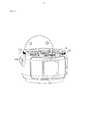
- FIG. 1 is a schematic view showing the assembly of a camera according to a first preferred embodiment of the present invention.
- FIG. 2 is an exploded perspective view of the camera shown in FIG. 1.
- FIG. 3 is an exploded perspective view of the camera shown in FIG. 2.
- FIG. 4 is an exploded perspective view of the limit structure shown in FIG. 3.
- Figure 5 is a partial assembled view of the position limiting structure shown in Figure 4 assembled on the camera.
- Figure 6 is a cross-sectional view of the camera of Figure 5 taken along line VI-VI.
- FIG. 7 is an exploded perspective view of the lens limiting assembly shown in FIG. 3.
- FIG. 7 is an exploded perspective view of the lens limiting assembly shown in FIG. 3.
- Figure 8 is an enlarged schematic view of a portion VIII of Figure 4.
- Figure 9 is a schematic view showing the assembly of the lens fitting ring and the locking ring shown in Figure 4.
- Figure 10 is a schematic view showing the assembly of the lens limiting assembly shown in Figure 4.
- Figure 11 is a cross-sectional view of the camera of Figure 1 taken along line XI-XI.
- Figure 12 is an enlarged schematic view of a portion XI of Figure 11.
- Figure 13 is an exploded perspective view of a lens limiting assembly according to a second preferred embodiment of the present invention.
- Figure 14 is a schematic side view of the lens assembly ring of Figure 13;
- Figure 15 is a schematic view showing the assembly of the lens assembly ring and the locking ring of Figure 14;
- FIG. 16 is a partially exploded perspective view showing the body of the camera according to the second preferred embodiment of the present invention.
- FIG. 17 is a schematic view showing the assembly of a camera body according to a second preferred embodiment of the present invention.
- FIG. 18 is a perspective view of the lens and the body of the camera according to the second preferred embodiment of the present invention.
- Figure 19 is a cross-sectional view of the lens of Figure 18 assembled with the body
- Figure 20 is an enlarged view of a portion XIX of Figure 7.
- Lens 310 Lens barrel 312 Assembly department 313 Card holder 314 Camera body 200 Fixed frame 210 Contact 215 First assembly hole 216 Second assembly hole 217 Mounting column 2171 Step surface 2173 Via 2174 Contact base mounting position 220 Locating pin 230 bolt 240 Limit structure 250 button 251 Key body 2511 First side 2512 Second side 2513 Card space 2514 Holder 2515 First card holding arm 2516 First slope 2517 surface 2518 Second card holding arm 2519 Limit boss 253 Tab 2531 support 2533 Shaft 2535 First support 2536 Second support 2537 Limit end 2538 Upper boss 2538a Lower boss 2538b Second slope 2538c Support end 2539 First elastic member 255 Second elastic member 257 Lens limit assembly 100 Elastic component 10 Elastic body 11 Elastic arm 12 First end 121 Second end 123 First positioning hole 14 Bayonet 16 Lens assembly ring 20 First end face twenty one Second positioning hole 211 Storage slot 213 Second end face twenty three Assembly hole 231 Bolt hole 233 Limiting department 25 Installation department 27 Locking ring 30 Ontology 31 hook up 33 Connection 331 Bending section 210
- a first preferred embodiment of the present invention provides a camera 300 , which may be a camera with a common detachable lens, a SLR camera with better imaging quality, or special use, such as no. Aerial camera used on the human machine.
- the camera 300 includes a lens 310, a camera body 200, and a lens limit assembly 100.
- the lens 310 is mounted in the camera body 200 through the lens limit assembly 100.
- the lens 310 includes a lens barrel 312.
- the bottom of the lens barrel 312 is provided with a mounting portion 313.
- the outer wall of the mounting portion 313 is provided with three mutually spaced latching bodies 314 for the lens limiting component 100. With the use of.
- the camera body 200 of the camera includes a fixing frame 210 , and the lens limiting component 100 is disposed in the fixing frame 210 .
- a contact 215 is disposed in the fixing frame 210 for electrically connecting with the driver in the lens 310 when the lens 310 is fastened and assembled.
- a plurality of contact base mounting positions 220 are formed on the fixing frame 210 for assembling the lens 310.
- a fixing pin 230 is further disposed on the fixing frame 210, and the four bolts 240 are extended and contracted by the limiting structure 250.
- the number of the positioning pin 230, the bolt 240 and the holding body 314 is not limited to the above number, and can be designed according to actual needs.
- the limiting structure 250 includes a button 251 , a limiting boss 253 , a first elastic member 255 , and a second elastic member 257 .
- the button 251 is connected to the limiting boss 253.
- the first elastic member 255 is disposed between the button 251 and the limiting boss 253.
- the second elastic member 257 is sleeved on the limiting boss 253.
- the button 251 is movably disposed on the side of the camera body 200 to facilitate user pressing.
- the button 251 includes a key body 2511 and two latching portions 2515 disposed on the key body 2511.
- the key body 2511 is substantially a rectangular parallelepiped structure including a first face 2512 and a second face 2513 disposed opposite each other.
- the first surface 2512 is adjacent to the limiting boss 253, and the second surface 2513 is away from the limiting boss 253.
- the two holding portions 2515 are vertically formed by two sides of the first surface 2512 facing away from the first surface 2512 and are spaced apart from each other.
- the second surface 2513 is for facilitating a user to press to control the Button 251.
- Each of the latching portions 2515 includes a first latching arm 2516 and a second latching arm 2519 that are integrally provided.
- One side of the first holding arm 2516 forms a first inclined surface 2517.
- the first inclined surface 2517 is inclined by the first surface 2512 of the key body 2511 in a direction away from the first surface 2512, that is, the first holding arm 2516 is parallel to the first surface 2512.
- the width in the direction gradually decreases from the first face 2512 toward the direction away from the first face 2512.
- the first latching arm 2516 further includes a surface 2518 opposite the first beveled surface 2517. In the present embodiment, the surface 2518 is planar.
- the second latching arm 2519 is disposed at one end of the first latching arm 2516 opposite to the first surface 2512 and substantially parallel to the first surface 2512 .
- the second clamping arm 2519 includes a clamping edge 2510 formed by a downward direction of the first slope 2517 opposite to the first surface 2512 in a direction parallel to the first surface 2512.
- a clamping space 2514 is formed between the clamping edge 2510 and the first inclined surface 2517 to clamp the limiting boss 253.
- the number of the holding portions 2515 is not limited to the above-mentioned number, and can be designed according to actual needs.
- the limiting boss 253 is movably disposed in the body 200 of the camera for relatively limiting the lens 310.
- the limiting boss 253 includes a protrusion 2531, a bracket 2533 and a shaft 2535.
- the boss 2531 and the shaft 2535 are disposed on opposite sides of the bracket 2533.
- the bracket 2533 is generally an inverted "L" structure including a first support portion 2536 and a second support portion 2537 that are disposed substantially perpendicular to each other.
- the protrusion 2531 is vertically disposed on the first support portion 2536.
- the shaft 2535 is vertically disposed on the other surface of the first support portion 2536 opposite to the protrusion 2531 and is in line with the protrusion 2531.
- the second support portion 2537 is disposed in parallel with the key body 2511 of the button 251.
- the two sides of the lower portion of the second support portion 2537 are respectively cut inwardly, so that two limit ends 2538 are formed on both sides of the second support portion 2537 and the two limit ends 2538 are located.
- Each of the limiting ends 2538 includes an upper boss 2538a and a lower boss 2538b that are convexly disposed with respect to the supporting end 2539.
- a second inclined surface 2538c is further formed on the lower boss 2538b. The inclination of the second slope 2538c matches the inclination of the first slope 2517.
- the outer wall of the fixing frame 210 defines a first mounting hole 216 toward the inside.
- the lens limiting component 100 includes a lens limiting ring 20 , and the lens limiting ring 20 is disposed on the fixing frame 210 .
- the lens mounting ring 20 defines a second mounting hole 217 toward a side of the lens 310.
- the button 251 and the first elastic member 255 are received in the body 200 of the camera through the first mounting hole 216.
- the limiting boss 253 and the second elastic member 257 pass through the second mounting hole 217. It is housed in the body 200 of the camera.
- the first assembly hole 216 and the second assembly hole 217 are internally connected to each other, so that the button 251, the first elastic member 255, the limiting boss 253 and the second elastic member 257 are assembled to each other.
- a mounting post 2171 is formed on the inside of the second mounting hole 217, and two sides of the mounting post 2171 form a stepped surface 2173.
- the center of the mounting post 2171 further defines a through hole 2174 to facilitate the shaft.
- the rod 2535 passes through to prevent the limit boss 253 from tilting.
- the supporting end 2539 of the limiting boss 253 is received between the two latching portions 2515 of the button 251, and the first latching arm 2516 of each of the latching portions 2515 passes through.
- Each of the limiting ends 2538, the first inclined surface 2517 of the first holding arm 2516 abuts against the second inclined surface 2538c of the lower boss 2538b of the limiting boss 253, respectively.
- the first elastic member 255 is elastically held between the first surface 2512 of the key body 2511 and the supporting end 2539, and the second elastic member 257 is sleeved on the shaft 2535. One end is abutted against the first support portion 2536, and the other end is abutted against the stepped surface 2173.
- the second inclined surface 2538c cooperates with the first inclined surface 2517, and the force along the first inclined surface 2517 can be decomposed into a thrust perpendicular to the key body 2511 and the key body. 2511 parallel downforce.
- the thrust compresses the first elastic member 255 toward the supporting end 2539, and the downward pressure acts on the second inclined surface 2538c to drive the limiting boss 253 to move downward, thereby compressing the second elastic member 257 and disengaging from the
- the first elastic member 255 and the second elastic member 257 are deformed and the button 251 is rebounded, and the protrusion 2531 is driven into the lens 310 to prevent the button 251 from being locked.
- the lens 310 rotates. During the rebound of the button 251, the clamping edge 2510 is clamped on the lower boss 2538b to prevent the button 251 from rebounding excessively from the first mounting hole 216.
- the lens limiting assembly 100 is used to lock the lens 310 and prevent the lens 310 from rotating or falling off from the axial direction of the camera body 200.
- the lens limiting assembly 100 includes a resilient member 10 , a lens assembly ring 20 , and a locking ring 30 .
- the lens assembly ring 20 is disposed on the elastic member 10 and received in the locking ring 30, and the locking ring 30 is rotatable relative to the lens assembly ring 20.
- the elastic member 10 includes an elastic body 11 and a plurality of elastic arms 12 disposed on the elastic body 11.
- the elastic body 11 is an annular elastic piece, and the number of the elastic arms 12 is three, and the three elastic arms 12 are disposed at an inner side of the elastic body 11 at intervals.
- each of the elastic arms 12 is formed to extend downward from the inner side of the elastic body 11 in the direction of the axis of the elastic body 11.
- the elastic arm 12 includes a first end 121 and a second end 123. The position of the first end 121 in the direction of the axis of the elastic body 11 is higher than the second end 123 in the axial direction of the elastic body 11.
- the position is such that a gap 13 is formed between the resilient arm 12 and the resilient body 11 to receive the components of the locking ring 30.
- the first positioning hole 14 and the bayonet 16 are further defined on the elastic body 11 .
- the bayonet 16 is formed by recessing an outer wall of the elastic body 11 , and the shape of the bayonet 16 is adapted to the limit structure 250 of the camera body 200 to be nested. The engagement on the limiting structure 250 is performed.
- the lens mount ring 20 includes a first end face 21 and a second end face 23 that are disposed opposite each other, the first end face 21 being disposed toward the elastic member 10, the second end face 23 being disposed away from the elastic member 10.
- a second positioning hole 211 is defined in the first end surface 21 , and the second positioning hole 211 is connected to the first positioning hole 14 through a positioning pin 230 of the camera body 200 of the camera. .
- a positioning pin 230 on the body 200 of the camera passes through the first positioning hole 14 and the second positioning hole 211 to fix the elastic member 10 and the lens mount 20 to the camera.
- the first end surface 21 further defines three mutually spaced receiving grooves 213 for receiving the components on the locking ring 30.
- An assembly hole 231 penetrating the first end surface 21 and the second end surface 23 is disposed on the second end surface 23, and the limiting boss 253 of the camera body 200 passes through the assembly hole 231.
- the lens 310 is positioned.
- a fourth bolt hole 233 is further formed in the second end surface 23 .
- the four bolt holes 233 are used to pass four bolts 240 on the body 200 of the camera to secure the lens mount 20 to the camera body 200 of the camera.
- the inner wall of the lens assembly ring 20 is a smooth surface, and three mutually spaced limiting portions 25 are protruded toward the inner side, and a mounting portion 27 is formed between each of the two limiting portions 25 to facilitate the lens 310.
- the retaining body 314 passes through and is mounted within the body 200 of the camera.
- the number of the elastic arm 12, the receiving groove 213 and the limiting portion 25 is not limited to the above number, and can be designed according to actual needs.
- the locking ring 30 includes a body 31, a hook 33 and a non-slip portion 35.
- the hook 33 and the anti-slip portion 35 are disposed on both inner and outer sides of the body 31.
- the body 31 is a ring structure, and the ring is larger in diameter than the lens assembly ring 20 to receive the lens assembly ring 20 therein.
- the hook 33 is formed inwardly from the inner side of the body 31.
- the hook 33 is substantially in an "L" shape, and includes a connecting portion 331 and a bent portion 333 which are integrally provided.
- the connecting portion 331 is connected to the inner wall of the body 31, and one end of the bent portion 333 is connected to the other end of the connecting portion 331 and extends straight.
- the end of the bent portion 333 extends toward a side close to the resilient arm 12 to form a flange 335 for abutting the resilient arm 12 of the elastic member 10.
- a side of the flange 335 facing the connecting portion 331 forms a slope 334 to connect the bent portion 333 and the flange 335 .
- FIG. 9 and FIG. 10 when the elastic member 10 and the lens assembly ring 20 are received in the locking ring 30 , the connecting portion 331 and the bending portion 333 of the hook 33 are received in the receiving slot. In 213, the flange 335 is received in the gap 13 and abuts the elastic arm 12.
- the anti-slip portion 35 may be a non-slip thread for preventing a slippery phenomenon when the user turns the locking ring 30.
- the elastic component 10 is nested and engaged on the limiting structure 250 through the bayonet 16 .
- the lens assembly ring 20 is received on the locking ring 30 and disposed on the elastic member 10 .
- the positioning pin 230 passes through the first positioning hole 14 of the elastic member 10 and the lens assembly ring 20 .
- the second positioning hole 211 thus connects the elastic member 10 and the lens assembly ring 20 in series; the limiting structure 250 passes through the mounting hole 231 of the lens assembly ring 20 and can protrude along the limiting structure 250
- the lens is telescoped to position the lens 310; the locking ring 30 is rotatably disposed outside the lens mounting ring 20, and the hook 33 is received in the receiving groove 213 and resists the elasticity.
- the elastic arm 12 of the element 10 is on.
- the retaining body 314 is slid into the lens mount ring 20 by the mounting portion 27, and then rotated.
- the lens 310 rotates the holding body 314 to the limiting portion 25 of the lens fitting ring 20 and the elastic arm 12, and then the locking ring 30 can be rotated in one direction, the flange of the hook 33 335 is slid by the second end 123 of the resilient arm 12 toward the first end 121 of the resilient arm 12, since the position of the first end 121 of the resilient arm 12 is higher than the position of the second end 123, Therefore, the flange 335 slides while pressing the elastic member 10, which in turn presses the catching body 314 of the lens 310 to move the lens 310 toward the camera body 200.
- the lens 310 is thus locked to the body 200 of the camera.
- the locking ring 30 is rotated in the opposite direction, the flange 335 of the hook 33 slides from the first end 121 of the resilient arm 12 toward the second end 123, thereby releasing the resilient arm 12, thereby The lens 310 and the camera body 200 of the camera are no longer locked, and the lens 310 can be taken out from the camera body 200 of the camera.
- the shape of the flange 335 of the hook 33 is not limited to the one shown in the above embodiment, and only needs to be higher than the distance between the first end 121 of the elastic arm 12 and the elastic body 11. .
- the lens mount ring 20 is not limited to being fixed to the body 200 of the camera by bolt holes and bolts, and may be fixed by means of glue or the like.
- a second preferred embodiment of the present invention provides a lens limiting assembly 500 that includes a resilient member 510 , a lens mount ring 520 , and a locking ring 530 .
- the lens mount ring 520 is disposed on the elastic member 510.
- the lens mount ring 520 is received in the lock ring 530, and the lock ring 530 is rotatable relative to the lens mount ring 520.
- the elastic member 510 is an annular elastic piece, and the inner side of the elastic piece extends three elastic arms 512 spaced apart from each other.
- a first positioning hole 514 and a bayonet 516 are defined in the elastic member 510.
- the bayonet 516 is opened inwardly from the outer wall of the elastic member 510 and is semicircular.
- the lens mounting ring 520 is disposed with a second positioning hole 528 facing the end surface of the elastic member 510.
- the second positioning hole 528 is a blind hole for a positioning pin corresponding to the first positioning hole 514 and passing through the camera body. Concatenation.
- the lens mount ring 520 is further provided with a matching hole 529 extending through the opposite end faces thereof for engaging with other components of the camera body, and 4 bolt holes 5291 lens assembly ring for fixing to the camera body.
- the inner wall of the 520 extends three spaced-apart limiting portions 522, and the lens mounting ring 520 is provided with three mutually spaced receiving grooves 527 toward the end surface of the elastic member 510.
- a first mating surface 524 is disposed on one side of each of the receiving slots 527.
- the bottom surface of the receiving groove 527 is a flat surface, and the first mating surface 524 is formed to extend outward from the bottom surface and is inclined along the circumferential direction of the lens mounting ring 520.
- the limiting portion 522 is a rib provided on the inner side of the lens mount ring 520.
- the left and right sides of each of the limiting portions 522 are smooth surfaces, and may directly form an inner wall surface of the lens fitting ring 520 or a sliding groove surface opened inward.
- each of the hooks 532 extends substantially in an L shape from the inner wall of the locking ring 530, and each of the hooks 532 has a connecting portion 5321 connected to the inner wall of the locking ring 530, and the connecting portion 5321 connected bent portion 5322.
- An end of each of the bent portions 5322 facing the surface of the lens mount ring 520 is provided with a second mating surface 534 inclined with respect to other portions of the surface, each of the bent portions 5322 and the second mating surface
- the other surface opposite 534 is plane 536.
- the second mating surface 534 is matched with the first mating surface 524. Each of the hooks 532 is received in a corresponding receiving slot 527. The second mating surface 534 abuts the first mating surface 524.
- the flat surface 536 is for resisting the resilient arm 512 of the resilient member 510.
- a lens (see FIG. 17) having three mutually spaced retaining members on the outside is ready to be fitted into the lens mount ring 520, and the catch portion slides into the lens mount ring 520 from the smooth surface 526 of the lens mount ring 520. Then, the locking portion can be rotated to the lower portion 522 and the elastic arm 512 of the elastic member 510 by rotating the lens, and then the user can rotate the locking ring 530 in a direction, the second mating surface of the hook 532
- the 534 moves on the first mating surface 524 and presses the elastic member 510 as the height of the first mating surface 524 increases.
- the elastic arm 512 of the elastic member presses the latching portion of the lens toward the camera body. That is, the lens is locked.
- the second mating surface 534 of the hook 532 moves in the opposite direction on the first mating surface 524 and releases the elastic member 510 as the height of the first mating surface 524 decreases. So that the lens can be rotated out.
- the camera body 600 of the embodiment of the present invention includes a fixing frame 610 having a contact base mounting position 612 for assembling a lens having a holding portion on the outer side.
- the contact base mounting position 612 is provided with the lens limit assembly 500.
- the fixing frame 610 further protrudes from a positioning pin 621 , four bolts 622 , and a limiting structure 650 .
- the elastic element 510 passes through the bayonet 516 and the retractable limiting structure 650 .
- the nut 651 is nested and snapped.
- the lens assembly ring 520 is coupled to the locking ring 530 and disposed on the elastic member 510.
- the positioning pin 621 passes through the first positioning hole 514 of the elastic member 510 and extends into the second lens assembly ring 520.
- the positioning hole 528 is connected in series with the elastic member 510 and the lens mounting ring 520; the four bolts 622 extend into the four bolt holes 5291 of the lens mounting ring 520 to fix the lens mounting ring 520; the retractable limiting structure
- the protrusion 652 of the 650 protrudes from the matching hole 529 of the lens assembly ring 520, and can be extended and contracted in the direction in which the protrusion 652 protrudes, and is positioned with the lens; the locking ring 530 is rotatably disposed on the lens assembly ring 520. periphery.
- the camera 800 includes a lens 700 and a camera body 600.
- the lens holder 700 has a lens barrel 712 having a mounting portion 713.
- the outer wall of the mounting portion 713 is provided with three mutually spaced apart holding bodies 714.
- the holding body 714 is a flange.
- the second mating face 534 of the hook 532 moves over the first mating face 524 and along the first mating face 524
- the elastic member 510 is pressed against the increase in the height in the direction perpendicular to the bottom surface of the receiving groove 527.
- the elastic arm 512 of the elastic member 510 presses the holding body 714 of the lens 700 toward the camera body 600 of the camera. That is, the locking lens 700 is attached to the body 600 of the camera.
- the second mating surface 534 of the hook 532 moves in the opposite direction on the first mating surface 524 and releases the elastic member 510 as the height of the first mating surface 524 decreases. Thereby the lens 700 can be rotated out of the body 600 of the camera.
- a contact 620 is disposed in the body 600 of the camera for electrically connecting to a driver or the like in the lens 700 when the lens 700 is fastened and assembled.
- the number of the elastic arm 512, the receiving groove 527, the limiting portion 522, the hook 532 and the holding body 714 is not limited to the above number, and can be designed according to actual needs.
- the shape of the hook 532 is not necessarily as shown in the above embodiment, but only needs to be able to stably slide between the first mating surface 524 and the elastic member 510.
- the lens mount ring 520 is not necessarily fixed by bolts and bolts of the camera body, but may be fixed by means of glue or the like.
- the lens limiting component provided by the embodiment of the invention is provided with a locking ring, and when the locking ring is screwed, the elastic component is pressed, thereby pressing the clamping portion of the lens, thereby locking the lens to prevent the lens from rotating and the shaft Fall off.
- the lens and the body can be locked to prevent the lens from rotating and axially falling off.
Landscapes
- Physics & Mathematics (AREA)
- General Physics & Mathematics (AREA)
- Engineering & Computer Science (AREA)
- General Engineering & Computer Science (AREA)
- Mechanical Engineering (AREA)
- Optics & Photonics (AREA)
- Structure And Mechanism Of Cameras (AREA)
- Lens Barrels (AREA)
Abstract
一种镜头限位组件(100),用于限位外侧设有卡持体(314)的镜头(310)。镜头限位组件(100)包括:弹性元件(10);镜头装配圈(20),设置在弹性元件(10)上,镜头(310)装配入镜头装配圈(20)后,卡持体(314)卡持在弹性元件(10)下方;和锁紧圈(30),锁紧圈(30)往一方向转动时,锁紧圈(30)抵持并压迫弹性元件(10),使弹性元件(10)压迫镜头的卡持体(314)从而锁紧镜头(310)。
Description
本发明涉及镜头限位组件,以及涉及具有镜头限位组件的相机的机身及具有所述机身的相机。
相机包含镜头和机身,镜头与机身固定或者可拆卸连接。要保证成像稳定,需要保证镜头到影像传感器的法兰距要尽量精确,这样成像才会稳定清晰。现有的相机镜头的装配方式是将镜头旋转安装到相机的机身上,靠机身上的镜头装配圈勾住,然后在镜头装配圈处增加一个镜头释放按钮组件,插入镜头里,防止镜头脱落。
上述方式中,镜头既然能旋转,通常至少有0.05mm左右的间隙,然而若相机用在有振动的平台上,将会导致后面的触点和相机镜头接触不是很好,甚至失效,另外镜头也可能因间隙而使法兰距微微变化。有设计者提出使用弹簧片消除上述间隙,然而弹簧片不够稳定,无法保证紧密配合程度。
本发明实施例主要解决的技术问题是提供一种镜头限位组件,可锁紧镜头,防止镜头旋转及轴向脱落。
本发明实施例主要解决的另一技术问题是提供一种具有所述镜头限位组件的相机的机身,可锁紧镜头,防止镜头旋转及轴向脱落。
本发明实施例主要解决的再一技术问题是提供一种具有所述机身的相机。
一方面,本发明实施例提供了一种镜头限位组件,用于限位外侧设有卡持体的镜头,所述镜头限位组件包括:弹性元件;镜头装配圈,所述镜头装配圈设置在所述弹性元件上,所述镜头装配入所述镜头装配圈后,所述卡持体卡持在弹性元件下方;以及锁紧圈,所述锁紧圈往一方向转动时,所述锁紧圈抵持并压迫所述弹性元件,使所述弹性元件压迫所述镜头的卡持体从而锁紧镜头。
另一方面,本发明实施例提供一种相机的机身,其包括固定框,所述固定框具有触点基托安装位置,用于装配外侧设有卡持体的镜头,所述触点基托安装位置设置有镜头限位组件,所述镜头限位组件包括:镜头装配圈,所述镜头装配圈设置在所述弹性元件上,所述镜头装配入所述镜头装配圈后,所述卡持体卡持在弹性元件下方;以及锁紧圈,所述锁紧圈往一方向转动时,所述锁紧圈抵持并压迫所述弹性元件,使所述弹性元件压迫所述镜头的卡持体从而锁紧镜头。
再一方面,本发明实施例提供一种相机,其包括相机的机身和镜头,所述相机的机身包括固定框,所述固定框具有触点基托安装位置,用于装配外侧设有卡持体的镜头,所述触点基托安装位置设置有镜头限位组件,所述镜头限位组件包括:弹性元件;镜头装配圈,所述镜头装配圈设置在所述弹性元件上,所述镜头装配入所述镜头装配圈后,所述卡持体卡持在弹性元件下方;以及锁紧圈,所述锁紧圈往一方向转动时,所述锁紧圈抵持并压迫所述弹性元件,使所述弹性元件压迫所述镜头的卡持体从而锁紧镜头。
本发明实施例提供的镜头限位组件设有锁紧圈,在拧锁紧圈时,弹性元件受到压迫,从而压紧镜头的卡持体,从而锁紧镜头,防止镜头旋转及轴向脱落。本发明实施例提供的相机的机身和相机,由于有所述镜头限位组件,镜头与机身可以锁紧,防止镜头旋转及轴向脱落。
图1是本发明第一较佳实施例提供的相机的装配示意图。
图2是图1所示的相机的分解示意图。
图3是图2所示的相机的分解示意图。
图4是图3所示的限位结构的分解示意图。
图5是图4所示的限位结构装配在所述相机上的部分装配示意图。
图6是图5中的相机沿VI-VI的剖视图。
图7是图3所示的镜头限位组件的分解示意图。
图8是图4中VIII部分的放大示意图。
图9是图4所示的镜头装配圈与锁紧圈的装配示意图。
图10是图4所示的镜头限位组件的装配示意图。
图11是图1所示的相机沿XI-XI的剖视图。
图12是图11中XI部分的放大示意图。
图13是本发明第二较佳实施例提供的镜头限位组件的分解立体图;
图14是图13的镜头装配圈的反面示意图;
图15是图14的镜头装配圈与锁紧圈的装配示意图;
图16是本发明第二较佳实施例提供的相机的机身的部分分解立体示意图;
图17是本发明第二较佳实施例提供的相机的机身的装配示意图;
图18是本发明第二较佳实施例提供的相机的镜头与机身装配前的立体示意图;
图19是图18的镜头与机身装配后的剖示图;
图20是图7中的XIX部分的放大图。
| 相机 | 300 |
| 镜头 | 310 |
| 镜筒 | 312 |
| 装配部 | 313 |
| 卡持体 | 314 |
| 相机的机身 | 200 |
| 固定框 | 210 |
| 触点 | 215 |
| 第一装配孔 | 216 |
| 第二装配孔 | 217 |
| 安装柱 | 2171 |
| 台阶面 | 2173 |
| 导通孔 | 2174 |
| 触点基托安装位置 | 220 |
| 定位销 | 230 |
| 螺栓 | 240 |
| 限位结构 | 250 |
| 按键 | 251 |
| 键体 | 2511 |
| 第一面 | 2512 |
| 第二面 | 2513 |
| 卡持空间 | 2514 |
| 卡持部 | 2515 |
| 第一卡持臂 | 2516 |
| 第一斜面 | 2517 |
| 表面 | 2518 |
| 第二卡持臂 | 2519 |
| 限位凸台 | 253 |
| 凸柱 | 2531 |
| 支架 | 2533 |
| 轴杆 | 2535 |
| 第一支撑部 | 2536 |
| 第二支撑部 | 2537 |
| 限位端 | 2538 |
| 上凸台 | 2538a |
| 下凸台 | 2538b |
| 第二斜面 | 2538c |
| 支撑端 | 2539 |
| 第一弹性件 | 255 |
| 第二弹性件 | 257 |
| 镜头限位组件 | 100 |
| 弹性元件 | 10 |
| 弹性本体 | 11 |
| 弹性臂 | 12 |
| 第一端 | 121 |
| 第二端 | 123 |
| 第一定位孔 | 14 |
| 卡口 | 16 |
| 镜头装配圈 | 20 |
| 第一端面 | 21 |
| 第二定位孔 | 211 |
| 收容槽 | 213 |
| 第二端面 | 23 |
| 装配孔 | 231 |
| 螺栓孔 | 233 |
| 限位部 | 25 |
| 安装部 | 27 |
| 锁紧圈 | 30 |
| 本体 | 31 |
| 挂钩 | 33 |
| 连接部 | 331 |
| 弯折部 | 333 |
| 凸缘 | 335 |
| 防滑部 | 35 |
| 镜头限位组件 | 500 |
| 弹性元件 | 510 |
| 第一定位孔 | 514 |
| 第二定位孔 | 528 |
| 配合孔 | 529 |
| 螺栓孔 | 291 |
| 卡口 | 516 |
| 镜头装配圈 | 520 |
| 锁紧圈 | 530 |
| 弹性臂 | 512 |
| 限位部 | 522 |
| 收容槽 | 527 |
| 第一配合面 | 524 |
| 平滑表面 | 526 |
| 挂钩 | 532 |
| 连接部 | 5321 |
| 弯折部 | 5322 |
| 第二配合面 | 534 |
| 平面 | 536 |
| 防滑槽 | 538 |
| 相机的机身 | 600 |
| 固定框 | 610 |
| 触点基托安装位置 | 612 |
| 镜头 | 700 |
| 镜筒 | 712 |
| 装配部 | 713 |
| 卡持体 | 714 |
| 触点 | 720 |
| 定位销 | 721 |
| 螺栓 | 722 |
| 可伸缩的限位结构 | 650 |
| 圆形螺母 | 651 |
| 凸柱 | 652 |
| 相机 | 800 |
如下具体实施方式将结合上述附图进一步说明本发明。
下面将结合本发明实施例中的附图,对本发明实施例中的技术方案进行清楚、完整地描述,显然,所描述的实施例仅仅是本发明一部分实施例,而不是全部的实施例。基于本发明中的实施例,本领域普通技术人员在没有做出创造性劳动前提下所获得的所有其他实施例,都属于本发明保护的范围。
请参照图1,本发明实施例第一较佳实施例提供一种相机300,所述相机300可以是普通可拆卸镜头的相机,成像品质较好的单反相机,或者是特殊使用的,例如无人机上使用的航拍相机等。请结合参照图2,所述相机300包括镜头310、相机的机身200和镜头限位组件100,所述镜头310通过所述镜头限位组件100安装于所述相机的机身200内。
所述镜头310包括镜筒312,所述镜筒312底端设置一装配部313,所述装配部313的外壁设有三个相互间隔的卡持体314,用于与所述镜头限位组件100配合使用。
请参阅图3,所述相机的机身200包括固定框210,所述镜头限位组件100设置在所述固定框210内。所述固定框210内设置有触点215,用于当镜头310紧固装配时与镜头310内的驱动器等电性连接。
所述固定框210上开设多个触点基托安装位置220,用于装配所述镜头310。所述固定框210上进一步设置一个定位销230,四个螺栓240伸缩的限位结构250。
可以理解,所述定位销230、所述螺栓240和所述卡持体314的数量不限于上述数量,可以根据实际需求设计。
请参阅图4,所述限位结构250包括按键251、限位凸台253、第一弹性件255和第二弹性件257。该按键251和该限位凸台253连接,该第一弹性件255设置在该按键251和该限位凸台253之间,该第二弹性件257套设在该限位凸台253上。
该按键251可活动地设置在该相机的机身200的侧面,以便于用户按压。该按键251包括键体2511及设置在该键体2511上的二个卡持部2515。该键体2511大致为一长方体结构,其包括相对设置的第一面2512和第二面2513。所述第一面2512靠近所述限位凸台253,而所述第二面2513远离所述限位凸台253。二个所述卡持部2515由所述第一面2512的两侧朝向远离所述第一面2512的方向垂直延伸形成且相互间隔设置,所述第二面2513用于便于用户按压以操控该按键251。每一卡持部2515包括一体设置的第一卡持臂2516和第二卡持臂2519。所述第一卡持臂2516的一侧形成一第一斜面2517。在本实施例中,该第一斜面2517由该键体2511的第一面2512朝向远离该第一面2512的方向倾斜,即所述第一卡持臂2516在沿平行该第一面2512的方向上的宽度由该第一面2512处开始朝向远离该第一面2512的方向逐渐减小。该第一卡持臂2516进一步包括一与该第一斜面2517相对的表面2518,在本实施例中,该表面2518为平面。该第二卡持臂2519设置在该第一卡持臂2516相对该第一面2512的一端且与该第一面2512大致平行设置。该第二卡持臂2519包括一夹持边2510,该夹持边2510由该第一斜面2517相对该第一面2512的一侧沿与该第一面2512平行的方向向下延伸形成。该夹持边2510与该第一斜面2517之间形成一卡持空间2514,以卡持该限位凸台253。
可以理解,所述卡持部2515的数量不限于上述数量,可以根据实际需求设计。
该限位凸台253可活动地设置在该相机的机身200内,用于相对限位该镜头310。该限位凸台253包括凸柱2531、支架2533及轴杆2535。该凸柱2531和该轴杆2535设置在该支架2533的相对两侧。该支架2533大致为一倒“L”结构,其包括大致相互垂直设置的第一支撑部2536和第二支撑部2537。该凸柱2531垂直设置在该第一支撑部2536上,该轴杆2535垂直设置在该第一支撑部2536相对该凸柱2531的另一面上且与该凸柱2531位于一条直线上。该第二支撑部2537与该按键251的键体2511平行设置。所述第二支撑部2537的中下部位置两侧分别向内切去部分切块,从而在该第二支撑部2537的两侧形成二个限位端2538以及位于该二个限位端2538中间位置的支撑端2539。每一所述限位端2538包括相对该支撑端2539凸出设置的上凸台2538a和下凸台2538b。所述下凸台2538b上进一步形成一第二斜面2538c。所述第二斜面2538c的倾斜度与所述第一斜面2517的倾斜度相匹配。
请结合参照图5及图6,该固定框210的外壁朝向内部开设一第一装配孔216。该镜头限位组件100包括镜头限位圈20,该镜头限位圈20设置在该固定框210上。该镜头装配圈20朝向该镜头310的一侧开设一第二装配孔217。该按键251和第一弹性件255穿过该第一装配孔216收容于所述相机的机身200内,该限位凸台253和该第二弹性件257穿过所述第二装配孔217收容于所述相机的机身200内。该第一装配孔216和该第二装配孔217内部相连通,以便于该按键251、该第一弹性件255、该限位凸台253和该第二弹性件257相互装配。
在本实施例中,该第二装配孔217的内部形成一安装柱2171,该安装柱2171的两侧形成台阶面2173,该安装柱2171的中心进一步开设导通孔2174,以便于所述轴杆2535穿过以防止该限位凸台253倾斜。
组装该限位结构250时,该限位凸台253的支撑端2539容置在该按键251的二卡持部2515之间,每一所述卡持部2515的第一卡持臂2516穿过每一所述限位端2538,所述第一卡持臂2516的第一斜面2517分别抵靠在该限位凸台253的下凸台2538b的第二斜面2538c上,该夹持边2510夹持在该下凸台2538b上,该第一弹性件255弹性抵持在该键体2511的第一面2512及该支撑端2539之间,该第二弹性件257套设在该轴杆2535上且一端抵持于该第一支撑部2536上,另一端抵持于该台阶面2173上。当使用者按压该按键251时,所述第二斜面2538c与所述第一斜面2517相互配合,该沿第一斜面2517的作用力可分解为垂直于该键体2511的推力和与该键体2511平行的下压力。该推力朝向该支撑端2539压缩该第一弹性件255,该下压力作用在该第二斜面2538c上并带动该限位凸台253向下运动,进而压缩所述第二弹性件257并脱离所述镜头310;当使用者不再按压该按键251时,该第一弹性件255和该第二弹性件257回复形变并带动该按键251回弹,同时带动该凸柱2531卡入镜头310以防止该镜头310旋转。当该按键251回弹过程中,该夹持边2510夹持在该下凸台2538b上,以防止该按键251回弹过度脱离该第一装配孔216。
所述镜头限位组件100用于锁紧所述镜头310并防止镜头310旋转或从所述相机的机身200的轴向脱落。
请结合参阅图7,所述镜头限位组件100包括弹性元件10、镜头装配圈20和锁紧圈30。所述镜头装配圈20设置在所述弹性元件10上并容置在所述锁紧圈30中,且所述锁紧圈30可相对所述镜头装配圈20转动。
所述弹性元件10包括弹性本体11和设置在所述弹性本体11上的多个弹性臂12。在本实施例中,所述弹性本体11为环状的弹片,所述弹性臂12的数量为三个,三个所述弹性臂12间隔地设置在所述弹性本体11的内侧。具体地,每一所述弹性臂12由所述弹性本体11的内侧沿所述弹性本体11轴线的方向向下延伸形成。所述弹性臂12包括第一端121和第二端123,所述第一端121在所述弹性本体11轴线的方向上的位置高于所述第二端123在所述弹性本体11轴线方向的位置,从而使得所述弹性臂12与所述弹性本体11之间形成一间隙13以容置所述锁紧圈30的元件。所述弹性本体11上进一步开设第一定位孔14和卡口16。本实施例中,所述卡口16为所述弹性本体11的外壁向内凹陷形成,所述卡口16的形状与所述相机的机身200的所述限位结构250相适应以嵌套卡合在所述限位结构250上。
所述镜头装配圈20包括相对设置的第一端面21和第二端面23,所述第一端面21朝向所述弹性元件10设置,所述第二端面23背离所述弹性元件10设置。请参阅图9,所述第一端面21上开设一第二定位孔211,所述第二定位孔211与所述第一定位孔14通过所述相机的机身200的一个定位销230串接。具体地,所述相机的机身200上的定位销230穿过所述第一定位孔14和所述第二定位孔211从而将所述弹性元件10和镜头装配圈20固定在所述相机的机身200上。所述第一端面21上进一步凹设三个相互间隔的收容槽213,用于收容所述锁紧圈30上的元件。所述第二端面23上设置一贯穿所述第一端面21和所述第二端面23的一装配孔231,所述相机的机身200的限位凸台253穿过所述装配孔231以定位所述镜头310。所述第二端面23上进一步开设四螺栓孔233。所述四螺栓孔233用于使得所述相机的机身200上的四个螺栓240穿过以将所述镜头装配圈20固定在所述相机的机身200上。
所述镜头装配圈20的内壁为平滑的表面,其朝向内侧凸设三个相互间隔的限位部25,每二所述限位部25之间形成一安装部27以便于所述镜头310的卡持体314穿过并安装在所述相机的机身200内。
可以理解,所述弹性臂12,所述收容槽213和所述限位部25的数量不限于上述数量,可以根据实际需求设计。
所述锁紧圈30包括本体31、挂钩33和防滑部35,所述挂钩33和所述防滑部35设置在所述本体31的内外两侧。所述本体31为一圆环结构,且所述圆环直径大于所述镜头装配圈20以收容所述镜头装配圈20于其内。所述挂钩33由所述本体31的内侧向内凸设形成,在本实施例中,所述挂钩33大致呈“L”型,其包括一体设置的连接部331和弯折部333。所述连接部331与所述本体31的内壁相连接,所述弯折部333一端连接在所述连接部331上另一端平直延伸。所述弯折部333的末端朝向靠近所述弹性臂12的一侧延伸形成一凸缘335,用于抵持所述弹性元件10的弹性臂12。请参阅图8,所述凸缘335朝向所述连接部331的一侧形成一斜面334以连接所述弯折部333与所述凸缘335。请结合参阅图9及图10,当所述弹性元件10和镜头装配圈20收容在所述锁紧圈30内时,所述挂钩33的连接部331和弯折部333收容于所述收容槽213内,所述凸缘335容置于所述间隙13中并抵持所述弹性臂12。当所述凸缘335相对所述弹性臂12运动并抵持所述弹性臂12时,所述斜面334接触所述弹性臂12,并使得所述凸缘335通过所述斜面334运动从而抵持在所述弹性臂12上,从而保证所述凸缘335与所述弹性臂12配合的流畅性。所述防滑部35可为防滑螺纹,其用于避免使用者转动所述锁紧圈30时出现滑手现象。
请参阅图6,当将所述镜头限位组件100装配在所述固定框210内时,所述弹性元件10通过所述卡口16嵌套卡合在所述限位结构250上,所述镜头装配圈20容置在所述锁紧圈30上并设置在所述弹性元件10上,所述定位销230穿过所述弹性元件10的第一定位孔14及所述镜头装配圈20的第二定位孔211从而串接所述弹性元件10和所述镜头装配圈20;所述限位结构250穿过所述镜头装配圈20的装配孔231并可沿所述限位结构250凸出的方向伸缩,从而定位所述镜头310;所述锁紧圈30可转动地设置在所述镜头装配圈20的外侧且所述挂钩33收容于所述收容槽213内并抵持于所述弹性元件10的弹性臂12上。
请结合参照图11及图12,当将所述镜头310装配入所述镜头装配圈20时,所述卡持体314由所述安装部27处滑入所述镜头装配圈20,随后通过旋转所述镜头310使卡持体314旋转至所述镜头装配圈20的所述限位部25及弹性臂12下方,然后可沿一方向旋转所述锁紧圈30,所述挂钩33的凸缘335由所述弹性臂12的第二端123朝向所述弹性臂12的第一端121滑动,由于所述弹性臂12的第一端121的位置高于所述第二端123在的位置,因此所述凸缘335滑动的同时压迫所述弹性元件10,所述弹性臂12进而压迫所述镜头310的卡持体314以使得所述镜头310朝向所述相机的机身200的方向运动,从而将所述镜头310锁紧于所述相机的机身200上。当沿相反方向旋转所述锁紧圈30时,所述挂钩33的凸缘335由所述弹性臂12的第一端121朝向所述第二端123滑动,进而释放所述弹性臂12,从而不再锁紧所述镜头310与所述相机的机身200,所述镜头310即可从所述相机的机身200中取出。
可以理解,所述挂钩33的凸缘335的形状不限于上述实施例的图中所示,仅需高度大于所述弹性臂12的第一端121与所述弹性本体11之间的距离即可。
在其它实施例中,所述镜头装配圈20不限于通过螺栓孔与螺栓的方式固定于所述相机的机身200上,也可以采用粘胶等方式固定。
请参阅图13至图15,本发明第二较佳实施例提供一种镜头限位组件500,该镜头限位组件500包括弹性元件510、镜头装配圈520和锁紧圈530。该镜头装配圈520设置在该弹性元件510上,该镜头装配圈520容置在该锁紧圈530中,且该锁紧圈530相对该镜头装配圈520可转动。
该弹性元件510为环状的弹片,该弹片的内侧延伸出3个相互间隔的弹性臂512。该弹性元件510上开设有第一定位孔514和卡口516。本实施例中,该卡口516由该弹性元件510的外壁向内开设,且为半圆形。
该镜头装配圈520朝向该弹性元件510的端面设置有第二定位孔528,该第二定位孔528为盲孔,用于与该第一定位孔514对应并通过相机的机身的一个定位销串接。该镜头装配圈520还设有贯穿其两相对端面,并用于与相机的机身的其它部件配合的1个配合孔529,以及用于与相机的机身固定的4个螺栓孔5291镜头装配圈520的内壁延伸出3个相互间隔的限位部522,且该镜头装配圈520朝向该弹性元件510的端面设有3个相互间隔的收容槽527。每个该收容槽527的一侧设置有一第一配合面524。本实施例中,该收容槽527的底面为平面,该第一配合面524由该底面向外延伸形成,且沿该镜头装配圈520的圆周方向倾斜。而该限位部522为设置于该镜头装配圈520的内侧的凸肋。每个该限位部522的左右两侧是平滑的表面,可以直接为该镜头装配圈520的内壁面或向内开设的滑槽面。
该锁紧圈530的外侧设有防滑槽538,内侧设有3个相互间隔的挂钩532。本实施例中,每个该挂钩532大致呈L形从该锁紧圈530的内壁延伸出,每个该挂钩532具有与该锁紧圈530的内壁连接的连接部5321,和与该连接部5321连接的弯折部5322。每个该弯折部5322的朝向所述镜头装配圈520的表面的端部设有一个相对该表面其它部位倾斜的第二配合面534,每个该弯折部5322与所述第二配合面534相对的另一表面是平面536。该第二配合面534的倾斜度与该第一配合面524相匹配,每个该挂钩532收容在一个对应的该收容槽527,该第二配合面534抵持该第一配合面524,该平面536用于抵持该弹性元件510的弹性臂512。
当外侧具有3个相互间隔的卡持体的镜头(见图17)准备装配入该镜头装配圈520,该卡持部自该镜头装配圈520的平滑表面526处滑入该镜头装配圈520,接下来可以通过旋转该镜头使卡持部旋转至该限位部522及弹性元件510的弹性臂512下方,然后使用者沿一方向可以旋转该锁紧圈530,该挂钩532的第二配合面534在该第一配合面524上运动且随该第一配合面524高度的增加而压迫该弹性元件510,该弹性元件的弹性臂512会压迫该镜头的卡持部向相机的机身方向,即锁紧镜头。当沿相反方向旋转该锁紧圈530时,该挂钩532的第二配合面534在该第一配合面524上反向运动且随该第一配合面524高度的减小而释放该弹性元件510,从而镜头可以旋转出来。
请一并参阅图16和图17,本发明实施例提供的相机的机身600包括固定框610,该固定框610具有触点基托安装位置612,用于装配外侧设有卡持部的镜头,该触点基托安装位置612设置有该镜头限位组件500。该固定框610还凸出有1个定位销621、4个螺栓622和设置有可伸缩的限位结构650,该弹性元件510通过该卡口516与该可伸缩的限位结构650的圆形螺母651嵌套卡合。该镜头装配圈520与该锁紧圈530配合好而设置在该弹性元件510上,该定位销621穿过该弹性元件510的第一定位孔514,并伸入该镜头装配圈520的第二定位孔528而串接该弹性元件510与该镜头装配圈520;该4个螺栓622伸入该镜头装配圈520的4个螺栓孔5291而固定该镜头装配圈520;该可伸缩的限位结构650的凸柱652伸出该镜头装配圈520的配合孔529,并可沿该凸柱652凸出的方向伸缩,与和镜头定位;该锁紧圈530可转动地设置在该镜头装配圈520外围。
请一并参阅图18至图20,本发明第二较佳实施例提供的相机800包括镜头700和相机的机身600。该镜头700具有镜筒712,该镜筒712具有一装配部713,该装配部713的外壁设有3个相互间隔的卡持体714,本实施例中,该卡持体714为凸缘。当该镜头700准备装配入该镜头装配圈520,该卡持体714自该镜头装配圈520的平滑表面526处滑入该镜头装配圈520,接下来可以通过旋转该镜头700使卡持体714旋转至该弹性元件510的弹性臂512下方,然后沿一方向可以旋转该锁紧圈530,该挂钩532的第二配合面534在该第一配合面524上运动且随该第一配合面524相对该收容槽527的底面相垂直方向上的高度的增加而压迫该弹性元件510,该弹性元件510的弹性臂512会压迫该镜头700的卡持体714向所述相机的机身600方向,即锁紧镜头700于所述相机的机身600上。当沿相反方向旋转该锁紧圈530,该挂钩532的第二配合面534在该第一配合面524上反向运动且随该第一配合面524高度的减小而释放该弹性元件510,从而镜头700可以从所述相机的机身600旋转出来。
该相机的机身600内设置有触点620,用于当镜头700紧固装配时与镜头700内的驱动器等电性连接。
可以理解,所述弹性臂512,所述收容槽527,所述限位部522,所述挂钩532及所述卡持体714的数量不限于上述数量,可以根据实际需求设计。
可以理解的是,所述挂钩532的形状不一定如上述实施例的图中所示,而仅需能够在第一配合面524与弹性元件510之间稳定滑动即可。
在其它实施例中,所述镜头装配圈520不一定通过螺栓孔与相机的机身的螺栓固定的方式,而可以采用粘胶等方式固定。
综上,本发明实施例提供的镜头限位组件设有锁紧圈,在拧锁紧圈时,弹性元件受到压迫,从而压紧镜头的卡持部,从而锁紧镜头,防止镜头旋转及轴向脱落。本发明实施例提供的相机的机身和相机,由于有所述限位组件,镜头与机身可以锁紧,防止镜头旋转及轴向脱落。
以上所述仅为本发明的实施例,并非因此限制本发明的专利范围,凡是利用本发明说明书及附图内容所作的等效结构或等效流程变换,或直接或间接运用在其他相关的技术领域,均同理包括在本发明的专利保护范围内。
Claims (40)
- 一种镜头限位组件,用于限位一镜头,所述镜头外侧设有卡持体,所述镜头限位组件包括:弹性元件;镜头装配圈,所述镜头装配圈设置在所述弹性元件上,所述镜头装配入所述镜头装配圈后,所述卡持体卡持在弹性元件下方;以及锁紧圈,所述锁紧圈往一方向转动时,所述锁紧圈抵持并压迫所述弹性元件,使所述弹性元件压迫所述镜头的卡持体从而锁紧镜头。
- 如权利要求1所述的镜头限位组件,其特征在于:所述弹性元件为环状的弹片,所述弹性元件包括弹性本体和弹性臂,所述弹性臂由所述弹性本体的内侧沿所述本体的轴线向下延伸形成,所述锁紧圈包括凸缘,所述凸缘抵持所述弹性臂。
- 如权利要求2所述的镜头限位组件,其特征在于:所述弹性臂包括第一端和第二端,所述第一端在所述本体轴线的方向上的位置高于所述第二端在所述弹性本体轴线的方向上的位置,从而使得所述弹性臂与所述弹性本体之间形成一间隙,所述凸缘容置在所述间隙内。
- 如权利要求2所述的镜头限位组件,其特征在于:所述锁紧圈包括本体和由所述本体朝向内侧凸设形成的挂钩,所述挂钩包括连接部和弯折部,所述连接部与所述本体的内壁相连接,所述镜头装配圈包括容置槽,所述连接部和所述弯折部容置于所述容置槽内,所述弯折部一端连接在所述连接部上另一端平直延伸,所述凸缘形成于所述弯折部的末端且朝向所述弹性臂延伸。
- 如权利要求4所述的镜头限位组件,其特征在于:所述凸缘朝向所述连接部的一侧形成一斜面,所述斜面连接所述凸缘和所述弯折部。
- 如权利要求1所述的镜头限位组件,其特征在于:所述镜头装配圈包括第一配合面,所述第一配合面设置在所述镜头装配圈朝向所述弹性元件的端面,且沿所述镜头装配圈的圆周方向倾斜。
- 如权利要求6所述的镜头限位组件,其特征在于:所述镜头装配圈的端面还设置有与所述第一配合面连接的收容槽,所述镜头装配圈容置在所述锁紧圈中,所述锁紧圈包括挂钩,所述挂钩自所述锁紧圈的内侧延伸出并收容在所述收容槽内,所述镜头装配圈包括与所述第一配合面抵持的第二配合面,所述第二配合面设置在所述挂钩的朝向所述镜头装配圈的表面的端部,所述挂钩相对所述第二配合面的另一个表面为平面,所述平面抵持所述弹性元件。
- 如权利要求7所述的镜头限位组件,其特征在于:所述挂钩包括与所述锁紧圈的内侧连接的连接部和自所述连接部弯折延伸的弯折部,所述第二配合面设置在所述弯折部朝向所述镜头装配圈的表面的端部,所述平面设置在所述弯折部与所述第二配合面相对的另一个表面。
- 如权利要求1所述的镜头限位组件,其特征在于:所述镜头装配圈包括限位部,所述限位部的左右两侧是平滑表面,供所述镜头自所述平滑表面滑入所述镜头装配圈后适于旋转使所述卡持体移动至所述限位部及弹性元件下方。
- 一种相机的机身,包括固定框及镜头限位组件,所述固定框具有触点基托安装位置,所述镜头限位组件设置在所述触点基托安装位置上,所述镜头限位组件用于限位一镜头,所述镜头外侧设有卡持体,所述镜头限位组件包括:弹性元件;镜头装配圈,所述镜头装配圈设置在所述弹性元件上,所述镜头装配入所述镜头装配圈后,所述卡持体卡持在弹性元件下方;以及锁紧圈,所述锁紧圈往一方向转动时,所述锁紧圈抵持并压迫所述弹性元件,使所述弹性元件压迫所述镜头的卡持体从而锁紧镜头。
- 如权利要求10所述的相机的机身,其特征在于:所述弹性元件为环状的弹片,所述弹性元件包括弹性本体和弹性臂,所述弹性臂由所述弹性本体的内侧沿所述本体的轴线向下延伸形成,所述锁紧圈包括凸缘,所述凸缘抵持所述弹性臂。
- 如权利要求11所述的相机的机身,其特征在于:所述弹性臂包括第一端和第二端,所述第一端在所述本体轴线的方向上的位置高于所述第二端在所述弹性本体轴线的方向上的位置,从而使得所述弹性臂与所述弹性本体之间形成一间隙,所述凸缘容置在所述间隙内。
- 如权利要求11所述的相机的机身,其特征在于:所述锁紧圈包括本体和由所述弹性本体朝向内侧凸设形成的挂钩,所述挂钩包括连接部和弯折部,所述连接部与所述弹性本体的内壁相连接,所述镜头装配圈包括容置槽,所述连接部和所述弯折部容置于所述容置槽内,所述弯折部一端连接在所述连接部上另一端平直延伸,所述凸缘形成于所述弯折部的末端且朝向所述弹性臂延伸。
- 如权利要求13所述的相机的机身,其特征在于:所述凸缘朝向所述连接部的一侧形成一斜面,所述斜面连接所述凸缘和所述弯折部。
- 如权利要求10所述的相机的机身,其特征在于:所述镜头装配圈包括第一配合面,所述第一配合面设置在所述镜头装配圈朝向所述弹性元件的端面,且沿所述镜头装配圈的圆周方向倾斜。
- 如权利要求15所述的相机的机身,其特征在于:所述镜头装配圈的端面还设置有与所述第一配合面连接的收容槽,所述镜头装配圈容置在所述锁紧圈中,所述锁紧圈包括挂钩,所述挂钩自所述锁紧圈的内侧延伸出并收容在所述收容槽内,所述镜头装配圈包括与所述第一配合面抵持的第二配合面,所述第二配合面设置在所述挂钩的朝向所述镜头装配圈的表面的端部,所述挂钩相对所述第二配合面的另一个表面为平面,所述平面抵持所述弹性元件。
- 如权利要求16所述的相机的机身,其特征在于:所述挂钩包括与所述锁紧圈的内侧连接的连接部和自所述连接部弯折延伸的弯折部,所述第二配合面设置在所述弯折部朝向所述镜头装配圈的表面的端部,所述平面设置在所述弯折部与所述第二配合面相对的另一个表面。
- 如权利要求10所述的相机的机身,其特征在于:所述镜头装配圈包括多个相互间隔的限位部,二个相邻的限位部之间形成一安装部,所述卡持体由所述安装部进入所述镜头装配圈并卡持在所述限位部的下方。
- 如权利要求10所述的相机的机身,其特征在于:所述固定框上设置一定位销和多个螺栓,所述弹性元件上开设第一定位孔,所述镜头装配圈包括相对设置的第一端面和第二端面,所述第一端面上开设第二定位孔,所述定位销穿过所述第一定位孔和所述第二定位孔,所述第二端面上开设多个螺栓孔,所述螺栓对应穿过所述螺栓孔。
- 如权利要求19所述的相机的机身,其特征在于:所述固定框进一步包括限位结构,所述弹性元件上开有卡口,所述限位结构与所述卡口嵌套卡合,所述镜头装配圈进一步开设贯穿所述第一端面和所述第二端面设置的装配孔,所述限位结构包括限位凸台,所述限位凸台穿过所述装配孔以定位所述镜头。
- 如权利要求10所述的相机的机身,其特征在于:该固定框上的外壁朝内开设一第一装配孔,该镜头装配圈朝向该镜头的一侧开设一第二装配孔,该第一装配孔和该第二装配孔相互连通,该限位结构进一步包括按键、第一弹性件和第二弹性件,该按键和该第一弹性件穿过该第一装配孔,该限位凸台和该第二弹性件穿过该第二装配孔。
- 如权利要求21所述的相机的机身,其特征在于:该按键包括键体和凸设于该键体上的二相互间隔的卡持部,每一所述卡持部包括相互连接的第一连接臂和第二连接臂,该第一连接臂包括一第一斜面,该第二连接臂包括夹持边,该夹持边由该第一斜面沿与该键体平行的方向向下延伸形成,该第一斜面抵靠该限位结构,该夹持边夹持该限位结构。
- 如权利要求21所述的相机的机身,其特征在于:该限位结构包括支架,凸柱和轴杆,该支架包括第一支撑部,该凸柱和该轴杆设置在该第一支撑部的相对两侧,该第二装配孔内形成安装柱,该安装柱两侧形成台阶面,该第二弹性件套设在该轴杆上且抵持于该第一支撑部和该台阶面之间,该安装柱上开有导通孔,该轴杆穿过该导通孔。
- 如权利要求23所述的相机的机身,其特征在于:该支架包括第二支撑部,该第二支撑部上部分朝向内侧形成二限位端及支撑端,该第一弹性件抵持于该键体和该支撑端之间,所述限位端包括相对设置的上凸台和下凸台,所述下凸台形成第二斜面,所述第一斜面抵靠在该第二斜面上,所述卡持部穿过所述限位端,所述夹持边夹持所述下凸台。
- 一种相机,包括镜头及相机的机身,所述相机的机身包括固定框及镜头限位组件,所述固定框具有触点基托安装位置,所述镜头限位组件设置在所述触点基托安装位置上,所述镜头限位组件用于限位所述镜头,所述镜头外侧设有卡持体,所述镜头限位组件包括:弹性元件;镜头装配圈,所述镜头装配圈设置在所述弹性元件上,所述镜头装配入所述镜头装配圈后,所述卡持体卡持在弹性元件下方;以及锁紧圈,所述锁紧圈往一方向转动时,所述锁紧圈抵持并压迫所述弹性元件,使所述弹性元件压迫所述镜头的卡持体从而锁紧镜头。
- 如权利要求25所述的相机,其特征在于:所述弹性元件为环状的弹片,所述弹性元件包括弹性本体和弹性臂,所述弹性臂由所述弹性本体的内侧沿所述本体的轴线向下延伸形成,所述锁紧圈包括凸缘,所述凸缘抵持所述弹性臂。
- 如权利要求26所述的相机,其特征在于:所述弹性臂包括第一端和第二端,所述第一端在所述本体轴线的方向上的位置高于所述第二端在所述弹性本体轴线的方向上的位置,从而使得所述弹性臂与所述弹性本体之间形成一间隙,所述凸缘容置在所述间隙内。
- 如权利要求26所述的相机,其特征在于:所述锁紧圈包括本体和由所述弹性本体朝向内侧凸设形成的挂钩,所述挂钩包括连接部和弯折部,所述连接部与所述弹性本体的内壁相连接,所述镜头装配圈包括容置槽,所述连接部和所述弯折部容置于所述容置槽内,所述弯折部一端连接在所述连接部上另一端平直延伸,所述凸缘形成于所述弯折部的末端且朝向所述弹性臂延伸。
- 如权利要求28所述的相机,其特征在于:所述凸缘朝向所述连接部的一侧形成一斜面,所述斜面连接所述凸缘和所述弯折部。
- 如权利要求25所述的相机,其特征在于:所述镜头装配圈包括第一配合面,所述第一配合面设置在所述镜头装配圈朝向所述弹性元件的端面,且沿所述镜头装配圈的圆周方向倾斜。
- 如权利要求30所述的相机,其特征在于:所述镜头装配圈的端面还设置有与所述第一配合面连接的收容槽,所述镜头装配圈容置在所述锁紧圈中,所述锁紧圈包括挂钩,所述挂钩自所述锁紧圈的内侧延伸出并收容在所述收容槽内,所述镜头装配圈包括与所述第一配合面抵持的第二配合面,所述第二配合面设置在所述挂钩的朝向所述镜头装配圈的表面的端部,所述挂钩相对所述第二配合面的另一个表面为平面,所述平面抵持所述弹性元件。
- 如权利要求31所述的相机,其特征在于:所述挂钩包括与所述锁紧圈的内侧连接的连接部和自所述连接部弯折延伸的弯折部,所述第二配合面设置在所述弯折部朝向所述镜头装配圈的表面的端部,所述平面设置在所述弯折部与所述第二配合面相对的另一个表面。
- 如权利要求25所述的相机,其特征在于:所述镜头装配圈包括多个相互间隔的限位部,二个相邻的限位部之间形成一安装部,所述卡持体由所述安装部进入所述镜头装配圈并卡持在所述限位部的下方。
- 如权利要求25所述的相机的机身,其特征在于:所述固定框上设置一定位销和多个螺栓,所述弹性元件上开设第一定位孔,所述镜头装配圈包括相对设置的第一端面和第二端面,所述第一端面上开设第二定位孔,所述定位销穿过所述第一定位孔和所述第二定位孔,所述第二端面上开设多个螺栓孔,所述螺栓对应穿过所述螺栓孔。
- 如权利要求34所述的相机,其特征在于:所述固定框进一步包括限位结构,所述弹性元件上开有卡口,所述限位结构与所述卡口嵌套卡合,所述镜头装配圈进一步开设贯穿所述第一端面和所述第二端面设置的装配孔,所述限位结构包括限位凸台,所述限位凸台穿过所述装配孔以定位所述镜头。
- 如权利要求25所述的相机,其特征在于:该固定框上的外壁朝内开设一第一装配孔,该固定框朝向该镜头的一侧开设一第二装配孔,该第一装配孔和该第二装配孔相互连通,该限位结构进一步包括按键、第一弹性件和第二弹性件,该按键和该第一弹性件容置在该第一装配孔内,该限位凸台和该第二弹性件容置在该第二装配孔内。
- 如权利要求36所述的相机,其特征在于:该按键包括键体和凸设于该键体上的二相互间隔的卡持部,每一所述卡持部包括相互连接的第一连接臂和第二连接臂,该第一连接臂包括一第一斜面,该第二连接臂包括夹持边,该夹持边由该第一斜面沿与该键体平行的方向向下延伸形成,该第一斜面抵靠该限位结构,该夹持边夹持该限位结构。
- 如权利要求36所述的相机,其特征在于:该限位结构包括支架,凸柱和轴杆,该支架包括第一支撑部,该凸柱和该轴杆设置在该第一支撑部的相对两侧,该第二装配孔内形成安装柱,该安装柱两侧形成台阶面,该第二弹性件套设在该轴杆上且抵持于该第一支撑部和该台阶面之间,该安装柱上开有导通孔,该轴杆穿过该导通孔。
- 如权利要求38所述的相机,其特征在于:该支架包括第二支撑部,该第二支撑部上部分朝向内侧形成二限位端及支撑端,该第一弹性件抵持于该键体和该支撑端之间,所述限位端包括相对设置的上凸台和下凸台,所述下凸台形成第二斜面,所述第一斜面抵靠在该第二斜面上,所述卡持部穿过所述限位端,所述夹持边夹持所述下凸台。
- 如权利要求25所述的相机,其特征在于:所述镜头包括镜筒,所述镜筒底端设置一装配部,所述卡持体间隔地设置在所述装配部的外壁上。
Priority Applications (8)
| Application Number | Priority Date | Filing Date | Title |
|---|---|---|---|
| EP20158592.4A EP3677965A1 (en) | 2014-10-27 | 2015-05-21 | Lens limiting assembly, camera body, and camera |
| EP15853756.3A EP3214493B1 (en) | 2014-10-27 | 2015-05-21 | Lens limiting assembly, camera body, and camera |
| CN201580000518.8A CN105518527B (zh) | 2014-10-27 | 2015-05-21 | 镜头限位组件、相机的机身及相机 |
| JP2016560425A JP6208896B2 (ja) | 2014-10-27 | 2015-05-21 | レンズ位置制限組立体、カメラのボディ及びカメラ |
| US15/497,368 US10073325B2 (en) | 2014-10-27 | 2017-04-26 | Lens limiting assembly, camera body and camera |
| US16/121,117 US10437135B2 (en) | 2014-10-27 | 2018-09-04 | Lens limiting assembly, camera body and camera |
| US16/575,055 US10859893B2 (en) | 2014-10-27 | 2019-09-18 | Lens limiting assembly, camera body and camera |
| US17/114,397 US11347136B2 (en) | 2014-10-27 | 2020-12-07 | Lens limiting assembly, camera body and camera |
Applications Claiming Priority (2)
| Application Number | Priority Date | Filing Date | Title |
|---|---|---|---|
| CNPCT/CN2014/089604 | 2014-10-27 | ||
| PCT/CN2014/089604 WO2016065518A1 (zh) | 2014-10-27 | 2014-10-27 | 镜头限位组件、相机的机身及相机模块 |
Related Child Applications (1)
| Application Number | Title | Priority Date | Filing Date |
|---|---|---|---|
| US15/497,368 Continuation US10073325B2 (en) | 2014-10-27 | 2017-04-26 | Lens limiting assembly, camera body and camera |
Publications (1)
| Publication Number | Publication Date |
|---|---|
| WO2016065893A1 true WO2016065893A1 (zh) | 2016-05-06 |
Family
ID=55724994
Family Applications (2)
| Application Number | Title | Priority Date | Filing Date |
|---|---|---|---|
| PCT/CN2014/089604 Ceased WO2016065518A1 (zh) | 2014-10-27 | 2014-10-27 | 镜头限位组件、相机的机身及相机模块 |
| PCT/CN2015/079521 Ceased WO2016065893A1 (zh) | 2014-10-27 | 2015-05-21 | 镜头限位组件、相机的机身及相机 |
Family Applications Before (1)
| Application Number | Title | Priority Date | Filing Date |
|---|---|---|---|
| PCT/CN2014/089604 Ceased WO2016065518A1 (zh) | 2014-10-27 | 2014-10-27 | 镜头限位组件、相机的机身及相机模块 |
Country Status (5)
| Country | Link |
|---|---|
| US (4) | US10073325B2 (zh) |
| EP (2) | EP3214493B1 (zh) |
| JP (1) | JP6208896B2 (zh) |
| CN (1) | CN105518525B (zh) |
| WO (2) | WO2016065518A1 (zh) |
Families Citing this family (28)
| Publication number | Priority date | Publication date | Assignee | Title |
|---|---|---|---|---|
| WO2016061773A1 (zh) | 2014-10-22 | 2016-04-28 | 深圳市大疆创新科技有限公司 | 可伸缩的限位结构、相机的机身和相机 |
| WO2016065518A1 (zh) * | 2014-10-27 | 2016-05-06 | 深圳市大疆创新科技有限公司 | 镜头限位组件、相机的机身及相机模块 |
| CN107404603B (zh) * | 2016-05-19 | 2021-05-04 | 环球兴国际有限公司 | 镜头适配器及其背锁式镜头固定装置 |
| JP6758974B2 (ja) * | 2016-07-20 | 2020-09-23 | キヤノン株式会社 | 電子機器、及び監視システム |
| USD856396S1 (en) * | 2016-08-31 | 2019-08-13 | Fujifilm Corporation | Lens for camera |
| CN111741202B (zh) * | 2017-10-11 | 2021-12-24 | 深圳市大疆灵眸科技有限公司 | 成像装置 |
| JP6521023B2 (ja) * | 2017-10-26 | 2019-05-29 | 株式会社ニコン | アクセサリ |
| USD896872S1 (en) * | 2018-01-22 | 2020-09-22 | Samyang Optics Co., Ltd | Interchangeable lens for camera |
| USD888804S1 (en) * | 2018-05-04 | 2020-06-30 | New Ideas Manufacturing LLC | Step-up ring |
| USD908162S1 (en) * | 2018-08-24 | 2021-01-19 | Samyang Optics Co., Ltd. | Interchangeable lens for camera |
| JP6521163B1 (ja) * | 2018-10-18 | 2019-05-29 | 株式会社ニコン | 交換レンズ |
| JP6794599B2 (ja) * | 2019-02-25 | 2020-12-02 | エスゼット ディージェイアイ テクノロジー カンパニー リミテッドSz Dji Technology Co.,Ltd | マウント、撮像装置、撮像システム、及び移動体 |
| TWI756523B (zh) * | 2019-03-12 | 2022-03-01 | 緯創資通股份有限公司 | 卡扣機構及電子裝置的承載結構 |
| CN110035212B (zh) * | 2019-05-21 | 2023-11-03 | 昆山丘钛微电子科技有限公司 | 摄像头模组及终端 |
| CN110240224A (zh) * | 2019-07-15 | 2019-09-17 | 珠海格力电器股份有限公司 | 发光件的安装结构及发光装置 |
| WO2021017380A1 (en) | 2019-07-29 | 2021-02-04 | Zhejiang Dahua Technology Co., Ltd. | Camera device |
| JP7490343B2 (ja) * | 2019-08-20 | 2024-05-27 | キヤノン株式会社 | フランジバック調整部材 |
| CN112511721B (zh) * | 2019-08-26 | 2022-07-08 | 杭州海康威视数字技术股份有限公司 | 摄像机 |
| CN112543263B (zh) * | 2019-09-20 | 2023-06-16 | 富泰华工业(深圳)有限公司 | 摄像头及电子装置 |
| JP6953663B1 (ja) * | 2020-08-03 | 2021-10-27 | エスゼット ディージェイアイ テクノロジー カンパニー リミテッドSz Dji Technology Co.,Ltd | マウント構造、及び撮像装置 |
| JP6957808B1 (ja) * | 2020-08-03 | 2021-11-02 | エスゼット ディージェイアイ テクノロジー カンパニー リミテッドSz Dji Technology Co.,Ltd | マウント構造、及び撮像装置 |
| CN112212143A (zh) * | 2020-09-25 | 2021-01-12 | 杭州未来已来科技有限公司 | 一种智能家居安全防盗装置 |
| CN214954298U (zh) * | 2021-05-19 | 2021-11-30 | 深圳市绎立锐光科技开发有限公司 | 镜头壳体、镜头模组及光源系统 |
| CN114542562A (zh) * | 2022-03-28 | 2022-05-27 | 重庆金山医疗机器人有限公司 | 连接组件、器械臂及手术机器系统 |
| CN115002321B (zh) * | 2022-05-27 | 2024-04-23 | 杭州海康威视数字技术股份有限公司 | 摄像机 |
| CN115202028B (zh) * | 2022-07-08 | 2024-04-12 | 嘉兴锐星光学仪器有限公司 | 一种内置导星功能且具有替换式镜头的天文摄星镜 |
| CN116366936A (zh) * | 2023-02-13 | 2023-06-30 | 杭州海康威视数字技术股份有限公司 | 摄像机 |
| WO2026048739A1 (ja) * | 2024-08-28 | 2026-03-05 | パナソニックプロジェクター&ディスプレイ株式会社 | レンズマウント機構およびそれを備えた投射型画像表示装置 |
Citations (7)
| Publication number | Priority date | Publication date | Assignee | Title |
|---|---|---|---|---|
| CN201104277Y (zh) * | 2007-11-07 | 2008-08-20 | 承奕科技股份有限公司 | 相机的附加镜头固定结构 |
| CN103064234A (zh) * | 2011-10-24 | 2013-04-24 | 索尼公司 | 附件和成像装置 |
| CN203250100U (zh) * | 2012-05-07 | 2013-10-23 | 奥林巴斯映像株式会社 | 光学设备 |
| CN103365043A (zh) * | 2012-04-10 | 2013-10-23 | 佳能株式会社 | 能够更换镜头的摄像设备及其镜头接口 |
| CN103608725A (zh) * | 2011-06-17 | 2014-02-26 | 理光映像有限公司 | 照相机机身 |
| JP2014157248A (ja) * | 2013-02-15 | 2014-08-28 | Nikon Corp | カメラ用アクセサリ |
| CN204178095U (zh) * | 2014-10-27 | 2015-02-25 | 深圳市大疆创新科技有限公司 | 镜头限位组件、相机的机身及相机模块 |
Family Cites Families (20)
| Publication number | Priority date | Publication date | Assignee | Title |
|---|---|---|---|---|
| US73325A (en) * | 1868-01-14 | John w | ||
| US3559542A (en) * | 1969-02-03 | 1971-02-02 | Camera Service Center Inc | Quick release and locking mechanism for a camera lens mounting |
| US3782260A (en) * | 1972-07-14 | 1974-01-01 | Eastman Kodak Co | Photographic camera with interchangeable lenses and bayonet lock |
| JPS5836726U (ja) * | 1981-03-25 | 1983-03-10 | ソニー株式会社 | レンズ装置 |
| JPH0623821B2 (ja) * | 1983-09-02 | 1994-03-30 | ミノルタカメラ株式会社 | バヨネットマウント装置とこの装置を用いる光学機器 |
| JP2512749B2 (ja) | 1987-05-22 | 1996-07-03 | 株式会社 タムロン | レンズマウント機構 |
| JP2942294B2 (ja) * | 1990-02-14 | 1999-08-30 | 旭光学工業株式会社 | 光学装置のマウント部材 |
| BE1013550A3 (nl) | 2000-06-09 | 2002-03-05 | Barco Nv | Objectiefbevestiging. |
| DE10121439A1 (de) * | 2001-04-27 | 2002-10-31 | Hensoldt & Soehne Optik | Rastmechanismus |
| JP4152168B2 (ja) | 2002-08-12 | 2008-09-17 | Thk株式会社 | レンズ取付機構及びプロジェクタ装置 |
| JP4555556B2 (ja) * | 2003-10-09 | 2010-10-06 | オリンパス株式会社 | レンズ交換式カメラシステム |
| JP4986501B2 (ja) * | 2006-04-28 | 2012-07-25 | 富士フイルム株式会社 | 光学オプション取付リング |
| JP4963914B2 (ja) * | 2006-09-25 | 2012-06-27 | ペンタックスリコーイメージング株式会社 | 交換式レンズ鏡筒及びレンズ鏡筒交換式カメラシステム |
| JP5086214B2 (ja) * | 2008-09-19 | 2012-11-28 | 株式会社日立製作所 | レンズ取付け機構、およびレンズ取付け機構を有するプロジェクタ装置 |
| CN103581508A (zh) | 2012-07-18 | 2014-02-12 | 派尔高公司 | 摄像机 |
| JP2015141382A (ja) * | 2014-01-30 | 2015-08-03 | ソニー株式会社 | 撮像装置および撮像システム |
| US9568808B2 (en) * | 2014-08-07 | 2017-02-14 | Houdinix Llc | Low-profile lens mount |
| WO2016061773A1 (zh) * | 2014-10-22 | 2016-04-28 | 深圳市大疆创新科技有限公司 | 可伸缩的限位结构、相机的机身和相机 |
| WO2016065518A1 (zh) * | 2014-10-27 | 2016-05-06 | 深圳市大疆创新科技有限公司 | 镜头限位组件、相机的机身及相机模块 |
| TWI660660B (zh) * | 2015-02-11 | 2019-05-21 | 佳能企業股份有限公司 | 連接模組及應用其之系統 |
-
2014
- 2014-10-27 WO PCT/CN2014/089604 patent/WO2016065518A1/zh not_active Ceased
- 2014-10-27 CN CN201480019859.5A patent/CN105518525B/zh not_active Expired - Fee Related
-
2015
- 2015-05-21 EP EP15853756.3A patent/EP3214493B1/en active Active
- 2015-05-21 WO PCT/CN2015/079521 patent/WO2016065893A1/zh not_active Ceased
- 2015-05-21 EP EP20158592.4A patent/EP3677965A1/en not_active Withdrawn
- 2015-05-21 JP JP2016560425A patent/JP6208896B2/ja not_active Expired - Fee Related
-
2017
- 2017-04-26 US US15/497,368 patent/US10073325B2/en active Active
-
2018
- 2018-09-04 US US16/121,117 patent/US10437135B2/en not_active Expired - Fee Related
-
2019
- 2019-09-18 US US16/575,055 patent/US10859893B2/en not_active Expired - Fee Related
-
2020
- 2020-12-07 US US17/114,397 patent/US11347136B2/en active Active
Patent Citations (7)
| Publication number | Priority date | Publication date | Assignee | Title |
|---|---|---|---|---|
| CN201104277Y (zh) * | 2007-11-07 | 2008-08-20 | 承奕科技股份有限公司 | 相机的附加镜头固定结构 |
| CN103608725A (zh) * | 2011-06-17 | 2014-02-26 | 理光映像有限公司 | 照相机机身 |
| CN103064234A (zh) * | 2011-10-24 | 2013-04-24 | 索尼公司 | 附件和成像装置 |
| CN103365043A (zh) * | 2012-04-10 | 2013-10-23 | 佳能株式会社 | 能够更换镜头的摄像设备及其镜头接口 |
| CN203250100U (zh) * | 2012-05-07 | 2013-10-23 | 奥林巴斯映像株式会社 | 光学设备 |
| JP2014157248A (ja) * | 2013-02-15 | 2014-08-28 | Nikon Corp | カメラ用アクセサリ |
| CN204178095U (zh) * | 2014-10-27 | 2015-02-25 | 深圳市大疆创新科技有限公司 | 镜头限位组件、相机的机身及相机模块 |
Non-Patent Citations (1)
| Title |
|---|
| See also references of EP3214493A4 * |
Also Published As
| Publication number | Publication date |
|---|---|
| JP6208896B2 (ja) | 2017-10-04 |
| EP3214493B1 (en) | 2020-04-01 |
| EP3214493A1 (en) | 2017-09-06 |
| JP2017509930A (ja) | 2017-04-06 |
| CN105518525B (zh) | 2018-02-02 |
| US20210088883A1 (en) | 2021-03-25 |
| CN105518525A (zh) | 2016-04-20 |
| EP3677965A1 (en) | 2020-07-08 |
| WO2016065518A1 (zh) | 2016-05-06 |
| US20180373124A1 (en) | 2018-12-27 |
| US10859893B2 (en) | 2020-12-08 |
| US10073325B2 (en) | 2018-09-11 |
| EP3214493A4 (en) | 2017-09-06 |
| US20200012176A1 (en) | 2020-01-09 |
| US11347136B2 (en) | 2022-05-31 |
| US10437135B2 (en) | 2019-10-08 |
| US20170227833A1 (en) | 2017-08-10 |
Similar Documents
| Publication | Publication Date | Title |
|---|---|---|
| WO2016065893A1 (zh) | 镜头限位组件、相机的机身及相机 | |
| US7555192B2 (en) | Connecting structure of optical connectors | |
| US20100149408A1 (en) | Accessory and accessory for image pickup apparatus | |
| CN113467158B (zh) | 影视灯 | |
| US9456114B2 (en) | Video surveillance component and video surveillance assembly | |
| WO2017071338A1 (zh) | 云台快速装拆装置以及具有其的无人机 | |
| US10432833B2 (en) | Interchangeable lens camera | |
| WO2019105358A1 (zh) | 一种马桶盖 | |
| CN204807892U (zh) | 镜头限位组件、相机的机身及相机 | |
| WO2015192791A1 (zh) | 一种快速拆装墙座组件及装拆方法及升降杆 | |
| CN105518527B (zh) | 镜头限位组件、相机的机身及相机 | |
| CN204178095U (zh) | 镜头限位组件、相机的机身及相机模块 | |
| CN216479919U (zh) | 一种摄影摄像云台快装板限位结构 | |
| CN111741202B (zh) | 成像装置 | |
| WO2016106749A1 (zh) | 易拆卸固定装置 | |
| CN105900009A (zh) | 相机和适配器 | |
| CN107105137A (zh) | 摄像装置外壳及摄像装置 | |
| CN212900483U (zh) | 一种夹持装置 | |
| US20130175411A1 (en) | Stand adapter for projector or recording device | |
| KR101109597B1 (ko) | 디지털 기기용 삼각대 어댑터 및 이를 구비한 삼각대 | |
| CN223137433U (zh) | 快拆装置及摄影系统 | |
| CN220020075U (zh) | 镜头壳、镜头组件及拍摄装置 | |
| JPS6243190Y2 (zh) | ||
| JPS6243189Y2 (zh) | ||
| JP2003179793A (ja) | 取付面側の取付機構部並びにバッテリー及びアダプター |
Legal Events
| Date | Code | Title | Description |
|---|---|---|---|
| 121 | Ep: the epo has been informed by wipo that ep was designated in this application |
Ref document number: 15853756 Country of ref document: EP Kind code of ref document: A1 |
|
| ENP | Entry into the national phase |
Ref document number: 2016560425 Country of ref document: JP Kind code of ref document: A |
|
| NENP | Non-entry into the national phase |
Ref country code: DE |
|
| REEP | Request for entry into the european phase |
Ref document number: 2015853756 Country of ref document: EP |