WO2016067631A1 - 硫化物ガラス及び結晶性固体電解質の製造方法、結晶性固体電解質、硫化物ガラス及び固体電池 - Google Patents
硫化物ガラス及び結晶性固体電解質の製造方法、結晶性固体電解質、硫化物ガラス及び固体電池 Download PDFInfo
- Publication number
- WO2016067631A1 WO2016067631A1 PCT/JP2015/005477 JP2015005477W WO2016067631A1 WO 2016067631 A1 WO2016067631 A1 WO 2016067631A1 JP 2015005477 W JP2015005477 W JP 2015005477W WO 2016067631 A1 WO2016067631 A1 WO 2016067631A1
- Authority
- WO
- WIPO (PCT)
- Prior art keywords
- solid electrolyte
- sulfide
- ppm
- crystalline solid
- peak
- Prior art date
- Legal status (The legal status is an assumption and is not a legal conclusion. Google has not performed a legal analysis and makes no representation as to the accuracy of the status listed.)
- Ceased
Links
Images




Classifications
-
- C—CHEMISTRY; METALLURGY
- C03—GLASS; MINERAL OR SLAG WOOL
- C03C—CHEMICAL COMPOSITION OF GLASSES, GLAZES OR VITREOUS ENAMELS; SURFACE TREATMENT OF GLASS; SURFACE TREATMENT OF FIBRES OR FILAMENTS MADE FROM GLASS, MINERALS OR SLAGS; JOINING GLASS TO GLASS OR OTHER MATERIALS
- C03C3/00—Glass compositions
- C03C3/32—Non-oxide glass compositions, e.g. binary or ternary halides, sulfides or nitrides of germanium, selenium or tellurium
-
- C—CHEMISTRY; METALLURGY
- C03—GLASS; MINERAL OR SLAG WOOL
- C03C—CHEMICAL COMPOSITION OF GLASSES, GLAZES OR VITREOUS ENAMELS; SURFACE TREATMENT OF GLASS; SURFACE TREATMENT OF FIBRES OR FILAMENTS MADE FROM GLASS, MINERALS OR SLAGS; JOINING GLASS TO GLASS OR OTHER MATERIALS
- C03C1/00—Ingredients generally applicable to manufacture of glasses, glazes, or vitreous enamels
- C03C1/02—Pretreated ingredients
-
- C—CHEMISTRY; METALLURGY
- C03—GLASS; MINERAL OR SLAG WOOL
- C03C—CHEMICAL COMPOSITION OF GLASSES, GLAZES OR VITREOUS ENAMELS; SURFACE TREATMENT OF GLASS; SURFACE TREATMENT OF FIBRES OR FILAMENTS MADE FROM GLASS, MINERALS OR SLAGS; JOINING GLASS TO GLASS OR OTHER MATERIALS
- C03C3/00—Glass compositions
- C03C3/32—Non-oxide glass compositions, e.g. binary or ternary halides, sulfides or nitrides of germanium, selenium or tellurium
- C03C3/321—Chalcogenide glasses, e.g. containing S, Se, Te
-
- C—CHEMISTRY; METALLURGY
- C03—GLASS; MINERAL OR SLAG WOOL
- C03C—CHEMICAL COMPOSITION OF GLASSES, GLAZES OR VITREOUS ENAMELS; SURFACE TREATMENT OF GLASS; SURFACE TREATMENT OF FIBRES OR FILAMENTS MADE FROM GLASS, MINERALS OR SLAGS; JOINING GLASS TO GLASS OR OTHER MATERIALS
- C03C4/00—Compositions for glass with special properties
- C03C4/14—Compositions for glass with special properties for electro-conductive glass
-
- H—ELECTRICITY
- H01—ELECTRIC ELEMENTS
- H01B—CABLES; CONDUCTORS; INSULATORS; SELECTION OF MATERIALS FOR THEIR CONDUCTIVE, INSULATING OR DIELECTRIC PROPERTIES
- H01B1/00—Conductors or conductive bodies characterised by the conductive materials; Selection of materials as conductors
- H01B1/06—Conductors or conductive bodies characterised by the conductive materials; Selection of materials as conductors mainly consisting of other non-metallic substances
-
- H—ELECTRICITY
- H01—ELECTRIC ELEMENTS
- H01B—CABLES; CONDUCTORS; INSULATORS; SELECTION OF MATERIALS FOR THEIR CONDUCTIVE, INSULATING OR DIELECTRIC PROPERTIES
- H01B1/00—Conductors or conductive bodies characterised by the conductive materials; Selection of materials as conductors
- H01B1/06—Conductors or conductive bodies characterised by the conductive materials; Selection of materials as conductors mainly consisting of other non-metallic substances
- H01B1/10—Conductors or conductive bodies characterised by the conductive materials; Selection of materials as conductors mainly consisting of other non-metallic substances sulfides
-
- H—ELECTRICITY
- H01—ELECTRIC ELEMENTS
- H01B—CABLES; CONDUCTORS; INSULATORS; SELECTION OF MATERIALS FOR THEIR CONDUCTIVE, INSULATING OR DIELECTRIC PROPERTIES
- H01B13/00—Apparatus or processes specially adapted for manufacturing conductors or cables
-
- H—ELECTRICITY
- H01—ELECTRIC ELEMENTS
- H01M—PROCESSES OR MEANS, e.g. BATTERIES, FOR THE DIRECT CONVERSION OF CHEMICAL ENERGY INTO ELECTRICAL ENERGY
- H01M10/00—Secondary cells; Manufacture thereof
- H01M10/05—Accumulators with non-aqueous electrolyte
- H01M10/052—Li-accumulators
-
- H—ELECTRICITY
- H01—ELECTRIC ELEMENTS
- H01M—PROCESSES OR MEANS, e.g. BATTERIES, FOR THE DIRECT CONVERSION OF CHEMICAL ENERGY INTO ELECTRICAL ENERGY
- H01M10/00—Secondary cells; Manufacture thereof
- H01M10/05—Accumulators with non-aqueous electrolyte
- H01M10/052—Li-accumulators
- H01M10/0525—Rocking-chair batteries, i.e. batteries with lithium insertion or intercalation in both electrodes; Lithium-ion batteries
-
- H—ELECTRICITY
- H01—ELECTRIC ELEMENTS
- H01M—PROCESSES OR MEANS, e.g. BATTERIES, FOR THE DIRECT CONVERSION OF CHEMICAL ENERGY INTO ELECTRICAL ENERGY
- H01M10/00—Secondary cells; Manufacture thereof
- H01M10/05—Accumulators with non-aqueous electrolyte
- H01M10/056—Accumulators with non-aqueous electrolyte characterised by the materials used as electrolytes, e.g. mixed inorganic/organic electrolytes
- H01M10/0561—Accumulators with non-aqueous electrolyte characterised by the materials used as electrolytes, e.g. mixed inorganic/organic electrolytes the electrolyte being constituted of inorganic materials only
- H01M10/0562—Solid materials
-
- H—ELECTRICITY
- H01—ELECTRIC ELEMENTS
- H01M—PROCESSES OR MEANS, e.g. BATTERIES, FOR THE DIRECT CONVERSION OF CHEMICAL ENERGY INTO ELECTRICAL ENERGY
- H01M4/00—Electrodes
- H01M4/02—Electrodes composed of, or comprising, active material
- H01M4/36—Selection of substances as active materials, active masses, active liquids
- H01M4/58—Selection of substances as active materials, active masses, active liquids of inorganic compounds other than oxides or hydroxides, e.g. sulfides, selenides, tellurides, halogenides or LiCoFy; of polyanionic structures, e.g. phosphates, silicates or borates
- H01M4/583—Carbonaceous material, e.g. graphite-intercalation compounds or CFx
- H01M4/587—Carbonaceous material, e.g. graphite-intercalation compounds or CFx for inserting or intercalating light metals
-
- H—ELECTRICITY
- H01—ELECTRIC ELEMENTS
- H01M—PROCESSES OR MEANS, e.g. BATTERIES, FOR THE DIRECT CONVERSION OF CHEMICAL ENERGY INTO ELECTRICAL ENERGY
- H01M4/00—Electrodes
- H01M4/02—Electrodes composed of, or comprising, active material
- H01M4/62—Selection of inactive substances as ingredients for active masses, e.g. binders, fillers
-
- H—ELECTRICITY
- H01—ELECTRIC ELEMENTS
- H01M—PROCESSES OR MEANS, e.g. BATTERIES, FOR THE DIRECT CONVERSION OF CHEMICAL ENERGY INTO ELECTRICAL ENERGY
- H01M2300/00—Electrolytes
- H01M2300/0017—Non-aqueous electrolytes
- H01M2300/0065—Solid electrolytes
- H01M2300/0068—Solid electrolytes inorganic
- H01M2300/008—Halides
-
- Y—GENERAL TAGGING OF NEW TECHNOLOGICAL DEVELOPMENTS; GENERAL TAGGING OF CROSS-SECTIONAL TECHNOLOGIES SPANNING OVER SEVERAL SECTIONS OF THE IPC; TECHNICAL SUBJECTS COVERED BY FORMER USPC CROSS-REFERENCE ART COLLECTIONS [XRACs] AND DIGESTS
- Y02—TECHNOLOGIES OR APPLICATIONS FOR MITIGATION OR ADAPTATION AGAINST CLIMATE CHANGE
- Y02E—REDUCTION OF GREENHOUSE GAS [GHG] EMISSIONS, RELATED TO ENERGY GENERATION, TRANSMISSION OR DISTRIBUTION
- Y02E60/00—Enabling technologies; Technologies with a potential or indirect contribution to GHG emissions mitigation
- Y02E60/10—Energy storage using batteries
Definitions
- the present invention relates to a method for producing a sulfide glass and a crystalline solid electrolyte.
- the present invention also relates to a crystalline solid electrolyte, sulfide glass, and a solid state battery.
- lithium ion secondary batteries With the recent development of mobile communication and information electronic devices, demand for high-capacity and lightweight lithium ion secondary batteries tends to increase. Most electrolytes exhibiting high lithium ion conductivity at room temperature are liquids, and many of the commercially available lithium ion secondary batteries use organic electrolytes. In the lithium ion secondary battery using this organic electrolyte, there is a risk of leakage, ignition or explosion, and a battery with higher safety is desired.
- Patent Documents 1 to 3 a sulfide-based solid electrolyte having high safety and high ionic conductivity.
- the sulfide-based solid electrolytes described in Patent Documents 1 to 3 exhibit high ionic conductivity by crystallizing heat-treated sulfide glass.
- the heating temperature range in which high ionic conductivity is exhibited is high. There was a problem that it was narrow and difficult to manufacture. In particular, when manufacturing equipment is enlarged for mass production, there is a problem that heating at a uniform temperature becomes difficult.
- A represents the peak area of peaks appearing in the range of 57.2 ppm to 58.3 ppm and 63.0 ppm to 64.5 ppm in the 31 PNMR spectrum analysis, and D represents the peak position.
- D represents the peak position.
- B represents the sum of the peak areas of all measured peaks.
- A represents the peak area of a peak appearing in the range of 57.2 ppm to 58.3 ppm and 63.0 ppm to 64.5 ppm in the 31 PNMR spectrum analysis
- C represents the peak position.
- the peak area of the peak appearing in the range of 56.6 ppm or more and 57.1 ppm or less is shown, and D is the peak area of the peak appearing in the range of 84.0 ppm or more and 86.0 ppm or less and 110 ppm or more and 113 ppm or less, B represents the sum of the peak areas of all measured peaks.) 4). 4.
- D represents the peak area of the peak appearing in the range of 84.0 ppm or more and 86.0 ppm or less and 110 ppm or more and 113 ppm or less in the 31 PNMR spectrum analysis
- B represents all the peaks measured. Indicates the total peak area.
- Tc1 is an exotherm that appears for the first time when differential thermothermal gravimetric measurement is performed from 20 ° C. to 600 ° C. at a heating rate of 10 ° C./min in a dry nitrogen atmosphere.
- Tc2 means the temperature of the exothermic peak that appears next to Tc1.
- Tc1 + 45 ⁇ Tc2 (9) (In the formula, Tc1 means the temperature of the exothermic peak that appears for the first time when differential thermothermal gravimetric measurement is performed from 20 ° C. to 600 ° C. at a heating rate of 10 ° C./min in a dry nitrogen atmosphere, Tc2 means the temperature of the exothermic peak that appears next to Tc1.) 10.
- the following crystalline solid electrolyte and the like are provided.
- 14 The crystalline solid according to any one of 11 to 13, wherein the molar ratio of lithium, phosphorus and sulfur (lithium element: phosphorus element: sulfur element) is 0.1 to 12: 1 to 2: 0.1 to 9 Electrolytes.
- 15. The crystalline solid electrolyte according to any one of 11 to 14, wherein phosphorus sulfide is used as a raw material, and the phosphorus sulfide contains 37 mol% or more of a P 4 S 9 structure. 16.
- Sulfurization which contains lithium, phosphorus and sulfur as constituent components and can obtain the crystalline solid electrolyte according to any one of 11 to 15 at least at one point or more when heat-treated at intervals of 1 ° C. in a temperature range of 160 to 350 ° C. Glass. 17. 17. The sulfide glass according to 16, having ionic conductivity. 18. An electrode mixture comprising a solid electrolyte and an electrode active material, wherein the solid electrolyte comprises at least one of the crystalline solid electrolyte according to any one of 11 to 15 and the sulfide glass according to 17. 19.
- An electrode including a first solid electrolyte and an electrode active material; and an electrolyte layer including a second solid electrolyte, and at least one of the first solid electrolyte and the second solid electrolyte is any one of 11 to 15 18.
- a solid state battery comprising at least one of the crystalline solid electrolyte according to claim 18 and the sulfide glass according to 17.
- the manufacturing method of the sulfide glass from which the crystalline solid electrolyte with easy manufacture is obtained can be provided. Further, according to the present invention, a sulfide glass having a wide crystallization temperature range can be provided. Moreover, according to the present invention, a crystalline solid electrolyte that can be easily produced can be provided.
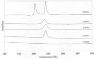
- FIG. 6 is a view showing the analysis results of the sulfide glass or crystalline solid electrolyte produced in Examples 1 to 5 by differential thermogravimetry.
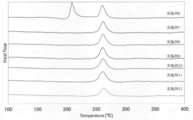
- FIG. 6 is a view showing the analysis results by differential thermogravimetry of the sulfide glass or crystalline solid electrolyte produced in Comparative Examples 1 to 5.
- FIG. 6 is a diagram showing the analysis results of differential thermal thermogravimetry of the sulfide glass or crystalline solid electrolyte produced in Examples 6-12.
- FIG. 6 is a view showing the analysis results by differential thermogravimetry of the sulfide glass or crystalline solid electrolyte produced in Comparative Examples 6 to 12.
- FIG. 6 is a view showing the analysis results by differential thermogravimetry of the sulfide glass or crystalline solid electrolyte produced in Examples 13 to 15.
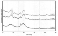
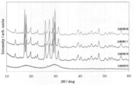
- 3 is a powder X-ray diffraction pattern of the sulfide glass or crystalline solid electrolyte produced in Examples 13 to 15.
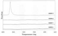
- FIG. 6 is a diagram showing the analysis results by differential thermogravimetry of the sulfide glass or crystalline solid electrolyte produced in Comparative Examples 15-18.
- 7 is a powder X-ray diffraction pattern of sulfide glass or crystalline solid electrolyte produced in Comparative Examples 15-18.
- the manufacturing method of sulfide glass of the first invention uses phosphorus sulfide according to the following formula (1) as a raw material.
- A represents the peak area of the peak appearing in the range of 57.2 ppm to 58.3 ppm and 63.0 ppm to 64.5 ppm in the 31 PNMR spectrum analysis
- B represents the measurement. The sum of the peak areas of all the peaks that are performed.
- the manufacturing method of the sulfide glass of the other aspect of 1st invention uses the phosphorus sulfide according to following formula (2) as a raw material.
- a and B are the same as the above formula (1).
- D represents the peak area of a peak appearing in the range of 84.0 ppm to 86.0 ppm and 110.0 ppm to 113.0 ppm in the 31 PNMR spectrum analysis.
- the method for producing a sulfide glass according to another aspect of the first invention uses phosphorus sulfide according to the following formulas (3) to (5) as a raw material.
- A, B and D are the same as the above formulas (1) and (2).
- C represents the peak area of a peak appearing in the range of 56.6 ppm or more and 57.1 ppm or less in the 31 PNMR spectrum analysis.
- phosphorus sulfides according to the above formulas (1) and (2) are preferably used as raw materials, and phosphorus sulfides according to the above formulas (1) to (5) are more preferably used as raw materials.
- the sulfide glass produced by the method for producing a sulfide glass of the first invention is heated.
- the method for producing the crystalline solid electrolyte of the first invention preferably conforms to the following formulas (7) and (8).
- T ⁇ Tc2 (8) (In the formula, T represents a heating temperature (° C., hereinafter, the unit of temperature is ° C., unless otherwise defined in units other than ° C.), and Tc 1 represents the sulfide glass by dry nitrogen. It means the temperature of the exothermic peak that appears for the first time when differential thermogravimetric measurement is performed from 20 ° C. to 600 ° C. at a heating rate of 10 ° C./min in an atmosphere.
- Tc2 is the temperature of the exothermic peak that appears next to Tc1. means.
- the temperature range of crystallization can be widened by producing sulfide glass using specific phosphorus sulfide as a raw material.
- mass producing a crystalline solid electrolyte it is difficult to uniformly heat the sulfide glass.
- the crystalline solid electrolyte has a wide temperature range. Can be produced.
- the temperature range represented by the formula (7) is preferably a temperature range represented by the following formula (7 ′).
- the condition of the formula (8) is preferably the following formula (8 ′).
- the term “crystalline solid electrolyte” refers to a peak derived from a crystal structure in which a peak other than a peak derived from a crystalline solid electrolyte raw material is observed in X-ray diffraction measurement, and the observed peak expresses ionic conductivity. Means a solid electrolyte.
- the crystal structure that expresses the peak is a single crystal structure or a plurality of crystal structures, and both a single crystal structure and a plurality of crystal structures. There can be.
- the peak derived from a crystalline solid electrolyte raw material does not ask
- require it is preferable that the peak derived from this raw material is small, and it is more preferable that there is no peak.
- the presence of a peak derived from the raw material indicates that an unreacted raw material remains, and depending on the type of the raw material, may cause a decrease in the ionic conductivity of the crystalline solid electrolyte.
- the “sulfide glass” is a halo pattern in which an X-ray diffraction pattern does not substantially show a peak other than a peak derived from a sulfide glass raw material in X-ray diffraction measurement.
- the sulfide glass may not have ionic conductivity, but preferably has it.
- the crystallinity of the crystalline solid electrolyte is not 100% and contains a sulfide glass component, the higher the ion conductivity of the sulfide glass, the higher the crystalline solid produced using this sulfide glass. This is because the ionic conductivity of the electrolyte is increased.
- the phosphorus sulfide includes an elemental compound containing elemental sulfur and an elemental phosphorus (for example, P 4 S 10 , P 4 S 9 , P 4 S 7 ), or two or more types of compounds including an elemental sulfur and an element of phosphorus (for example, P 4 S 10, P 4 phosphorus sulfide consisting of S 9 and P 4 S 7).
- P 4 S 9 has a peak position of 57.2 ppm to 58.3 ppm and 63.0 ppm to 64
- the peak position can be specified by a peak appearing in the range of 5 ppm or less
- P 4 S 10 can be specified by the peak appearing in the range of 56.6 ppm or more and 57.1 ppm or less
- P 4 S 7 is the peak position.
- the definitions of A, B, C and D described later are the same as those in the above formulas (1) to (5).
- “100 ⁇ A / B” uses phosphorus sulfide satisfying the requirement of 37.0 or more as a raw material, Phosphorous sulfide satisfying the requirement of “100 ⁇ A / B” of 38.0 or more is used.
- “100 ⁇ A / B” may be phosphorus sulfide satisfying the requirement of 40.0 or more and 42.0 or more.
- the upper limit of “100 ⁇ A / B”, which is a requirement that is satisfied or preferably satisfied by phosphorus sulfide, is not particularly limited, but may be 99, 95, or 90, for example. Even if phosphorus sulfide satisfying the requirements of “100 ⁇ C / B” from 25 to 60, “100 ⁇ A / B” from 37 to 60, and “100 ⁇ D / B” from 0 to 10 is used. Good.
- the phosphorus sulfide used is “100 ⁇ D / B” ⁇
- the phosphorus sulfide is preferably “100 ⁇ C / B "is phosphorus sulfide satisfying the requirements of 25 to 60," 100xA / B "is 37 to 60, and" 100xD / B "is 0 to 10 and more preferably” 100x Phosphorus sulfide satisfying the requirements of “C / B” of 30 to 55, “100 ⁇ A / B” of 37 to 55, and “100 ⁇ D / B” of 0 to 6 and more preferably “100 XC / B is phosphorus sulfide that satisfies the requirements of 35 to 55, “100 ⁇ A / B” is 38 to 50, and “100 ⁇ D / B” is 0 to 4 inclusive.
- phosphorus sulfide is preferably “100 ⁇ C / B "is phosphorus sulfide satisfying the requirements of 25 to 60," 100x
- the phosphorus sulfide to be used is “100 ⁇ D / B” ⁇ 0, it is preferable to satisfy the following formula (10), more preferably to satisfy the following formula (11), and to satisfy the following formula (12). And more preferred. 37 ⁇ X + Y ⁇ 70 (10) 37 ⁇ X + Y ⁇ 61 (11) 38 ⁇ X + Y ⁇ 54 (12) (In the formula, X represents “100 ⁇ A / B” in the phosphorous sulfide, and Y represents “100 ⁇ D / B” in the phosphorous sulfide.)
- the phosphorus sulfide may contain other components other than P 4 S 7, P 4 S 9 and P 4 S 7, the Other components such polysulfide phosphorus and the like.
- the ratio of the other components “100 ⁇ E / B” satisfies the requirement of 0 or more and 35 or less, more preferably satisfies the requirement of 0 or more and 30 or less, and more preferably satisfies the requirement of 0 or more and 10 or less.
- E is less than 56.6 ppm, greater than 57.1 ppm, less than 57.2 ppm, greater than 58.3 ppm, less than 63.0 ppm, greater than 64.5 ppm, and greater than 64.5 ppm in 31 PNMR spectral analysis.
- the sum of peak areas of peaks appearing in a range smaller than 0 ppm, larger than 86.0 ppm, smaller than 110.0 ppm and larger than 113.0 ppm is shown.
- B is the same as the above formula (1).
- the phosphorus sulfide to be used preferably satisfies “100 ⁇ D / B” of 0.1 or more and 10 or less.
- the phosphorous sulfide to be used satisfies the condition of “100 ⁇ D / B”> 0, the phosphorous sulfide is preferably “100 ⁇ C / B” of 25 to 60 and “100 ⁇ A / B” of 37.
- phosphorus sulfide containing P 4 S 7 preferably satisfies the following formula (10), more preferably satisfies the following formula (11), and further preferably satisfies the following formula (12).
- 37 ⁇ X + Y ⁇ 70 (10) 37 ⁇ X + Y ⁇ 61 (11)
- X represents “100 ⁇ A / B” in the phosphorous sulfide
- Y represents “100 ⁇ D / B” in the phosphorous sulfide.
- the phosphorus sulfide may contain other components other than P 4 S 7, P 4 S 9 and P 4 S 7, the Other components such polysulfide phosphorus and the like.
- the content of other components in phosphorus sulfide is preferably “100 ⁇ E / B”, preferably satisfies the requirement of 0 to 35, more preferably satisfies the requirement of 0 to 30 and more preferably 0 to 10 Satisfy requirements.
- P 4 S 9 includes ⁇ -type P 4 S 9 and ⁇ -type P 4 S 9 , and any of them may be used in the production method of the present invention.
- ⁇ -type P 4 S 9 and ⁇ -type P 4 S 9 have different molecular structures.
- P 4 S 9 is a molecule lacking a part of the structure of diphosphorus pentasulfide (molecular formula: P 4 S 10 ), and the commercially available diphosphorus pentasulfide has a low P 4 S 9 content.
- Phosphorus sulfide satisfying the requirement of “100 ⁇ A / B” of 37.0 or more may be produced by performing the following treatment on phosphorous pentasulfide, that is, phosphorous pentasulfide containing P 4 S 9 . Specifically, it is obtained by a Soxhlet extraction method using carbon disulfide as a solvent.
- the Soxhlet extraction method is an extraction method generally used for extracting a target component from a solid.
- the flask containing the solvent at the bottom was heated to evaporate the solvent, and the droplets condensed by the cooler at the top were dropped onto the cylindrical filter paper containing the sample at the middle to dissolve the target components. It is poured into the flask later. This is extracted in a constant cycle (hereinafter referred to as an extraction cycle) for a fixed time (hereinafter referred to as an extraction time), whereby the target component is concentrated in the solvent in the flask. More specifically, in a Soxhlet extraction method using carbon disulfide as a solvent, it is 2 to 10 times per hour, preferably 3 to 9 times per hour, for example, 1 to 4 extraction cycles.
- Extraction is performed for a time period of 48 hours or less and preferably 2 hours or more and 48 hours or less, for example 24 hours.
- the resulting extract is evaporated to dryness and then volatile material remaining in the extract is removed under vacuum (less than 1 Torr or less than about 130 Pa, ambient temperature). Thereby, phosphorus sulfide satisfying the requirement that “100 ⁇ A / B” is 37.0 or more is obtained.
- the water content of carbon disulfide as a solvent is preferably 100 ppm or less.
- diphosphorus pentasulfide is extracted by Soxhlet extraction method using carbon disulfide as a solvent for 24 hours with 4 to 5 extraction cycles per hour.
- the resulting extract is evaporated to dryness and the remaining volatiles are then removed under vacuum (less than 1 Torr or less than about 130 Pa, ambient temperature).
- vacuum less than 1 Torr or less than about 130 Pa, ambient temperature.
- the phosphorus sulfide used as a raw material preferably contains P 4 S 10 .
- “100 ⁇ D / B” contained in phosphorus sulfide is preferably 60.0 or less, more preferably 58.0 or less, and further preferably 55.0 or less.
- “100 ⁇ D / B” may satisfy the requirement of 50.0 or less, 45.0 or less, 40.0 or less.
- the phosphorus sulfide used as a raw material preferably contains P 4 S 7 .
- “100 ⁇ (A + D) / B” in phosphorus sulfide may satisfy the requirement of 40.0 or more and 45.0 or more.
- the phosphorus sulfide only needs to satisfy the requirement of “100 ⁇ A / B” of 37.0 or more, and may further include P 4 S 10 and / or P 4 S 7 , P 4 S 9 , P 4 S 10 and It may consist of P 4 S 7 .
- “100 ⁇ (A + C + D) / B” may satisfy the requirements of 85 or more, 90 or more, and 95 or more.
- the values A to E can be calculated from the results of 31 PNMR spectrum.
- the measurement conditions are as follows. Here, the value to be measured is the peak area of each peak, but the values A to E can be obtained by the method described above.
- Solution preparation 7 ml of carbon disulfide (Aldrich made by Aldrich) is added to 20 mg of a sample and completely dissolved. Further, 1 ml of benzene-d6 (99.6% made by ISOTEC) is added and stirred, and 0.7 ml of that is filled into the NMR sample tube.
- Apparatus ECA-500 NMR apparatus manufactured by JEOL RESONANCE Co., Ltd.
- the chemical shift can be obtained by using a deuterium solution of 85% phosphoric acid (chemical shift 0 ppm) as an external reference.
- the raw material preferably contains lithium sulfide.
- lithium sulfide will be described.
- the lithium sulfide used as a raw material is not particularly limited, and for example, commercially available ones can be used, and Japanese Patent Application Laid-Open Nos. 7-330121, 9-283156, 2010-163356, Lithium sulfide that can be produced by the method disclosed in JP 2011-084438 A can be used.
- JP-A-2010-163356 lithium hydroxide and hydrogen sulfide are reacted at 70 ° C. to 300 ° C. in a hydrocarbon organic solvent to produce lithium hydrosulfide, and then this reaction solution is desulfurized. Lithium sulfide is synthesized by hydrogenation.
- JP 2011-084438 A lithium hydroxide and hydrogen sulfide are reacted at 10 ° C. to 100 ° C. in an aqueous solvent to produce lithium hydrosulfide. To synthesize lithium sulfide.
- the obtained lithium sulfide can be used as it is without purification because it contains a very small amount of lithium oxide such as a lithium salt of sulfur oxide.
- a preferable purification method includes, for example, a purification method disclosed in International Publication WO2005 / 40039, and the obtained lithium sulfide is washed with an organic solvent at a temperature of 100 ° C. or higher. To purify.
- the raw material may contain lithium halide.
- the lithium halide include LiI, LiBr, LiCl, and LiF. One of these may be used, or two or more may be used.
- the mixing may be performed without using balls or beads, or may be performed in the presence of balls or beads, and preferably mixed in the presence of balls or beads.
- the mixing may be performed without using a solvent, or may be performed in a solvent.
- a solvent a method of circulating a reaction vessel using balls and beads and a reaction vessel not using balls and beads is preferable.
- the solvent may be a polar solvent or a nonpolar solvent.
- Nonpolar solvents include hydrocarbon solvents. Examples of the hydrocarbon solvent include aliphatic hydrocarbon solvents and aromatic hydrocarbon solvents, and mixing in an aromatic hydrocarbon solvent is preferable.
- the aromatic hydrocarbon solvent alkylbenzene is preferable.
- alkylbenzene toluene is preferable.
- the temperature at the time of mixing does not have limitation in particular, For example, they are 0 degreeC or more and 150 degrees C or less, 5 degrees C or more and 140 degrees C or less.
- the boiling point of the solvent or less is preferred.
- the mixing time is not particularly limited, but is, for example, 1 hour to 72 hours, 2 hours to 48 hours.
- the mixing ratio of lithium sulfide, phosphorus sulfide and lithium halide during mixing may be such that the molar ratio of lithium element, phosphorus element and halogen element is 120 to 165: 20 to 65: 5 to 35. preferable.
- the mixing ratio of lithium sulfide and phosphorus sulfide is preferably 85 to 60:15 to 40, and more preferably 85 to 65:15:35.
- the sulfide glass of the first invention may be manufactured by the above-described method for manufacturing a sulfide glass.
- the crystalline solid electrolyte of the first invention may be manufactured by the above-described method for manufacturing a crystalline solid electrolyte.
- the sulfide glass of the first invention may comply with the formula (9).
- Tc1 means the temperature of an exothermic peak that appears for the first time when a differential temperature thermogravimetry is performed from 20 ° C. to 600 ° C. at a heating rate of 10 ° C./min in a dry nitrogen atmosphere. Means the temperature of the exothermic peak that appears next to Tc1.
- the sulfide glass of 1st invention contains a sulfur element and a lithium element.
- the sulfide glass of the first invention preferably contains a sulfur element, a lithium element and a phosphorus element.
- the sulfide glass of the first invention may contain a sulfur element, a lithium element, a phosphorus element, and a halogen element.
- the first sulfide glass preferably has ionic conductivity.
- the halogen element is preferably bromine or iodine.
- the sulfide glass of the first invention preferably satisfies the formula (9 ′). Tc1 + 50 ⁇ Tc2 (9 ′) (In the formula, Tc1 and Tc2 are the same as in formula (9).)
- the crystalline solid electrolyte obtained by the production method of the first invention or the sulfide glass of the first invention is a crystalline sulfide solid electrolyte or sulfide glass containing Li, P and S.
- the crystalline solid electrolyte obtained by the production method of the first invention or the sulfide glass of the first invention may be a crystalline solid electrolyte or sulfide glass containing Li, P, S and halogen.
- the crystalline solid electrolyte obtained by the production method of the first invention or the sulfide glass of the first invention is specifically a crystalline solid electrolyte or sulfide glass containing Li, P and S, Li, P, S and Examples include crystalline solid electrolytes or sulfide glasses containing I, crystalline solid electrolytes or sulfide glasses containing Li, P, S and Br, crystalline solid electrolytes or sulfide glasses containing Li, P, S and Cl. .
- the crystalline solid electrolyte of the first invention or the sulfide glass of the first invention preferably has a composition represented by the following formula (13).
- M represents an element selected from B, Zn, Si, Cu, Ga, or Ge.
- X represents an element selected from F, I, Br, Cl, or At. a to e indicate the composition ratio of each element, and a: b: c: d: e satisfies 0.1 to 12: 0 to 0.2: 1 to 2: 0.1 to 9: 0 to 9.
- the crystalline solid electrolyte is at least partly crystallized.
- the glass transition point is a temperature at which atoms and ions can move, and in a glass having a glass transition point or higher, the diffusion and movement of structural units become remarkable.
- crystallization means that rearrangement between atoms occurs due to diffusion and movement of structural units in a glass having a disordered atomic arrangement structure, and changes into a crystalline phase through a two-stage process of nucleation and crystal growth, that is, The atomic arrangement structure has regularity (see NEW GLASS, 20 (3) 2005). From the above, it is considered that crystallization occurs at a temperature at which “diffusion or movement of structural units” is possible, that is, at a temperature higher than at least the vicinity of the glass transition point.
- Tc1 the glass transition point
- the heating temperature at which the crystal structure can be obtained is the exothermic heat that appears next to Tc1 when differential thermothermal gravimetric measurement is performed from 20 ° C. to 600 ° C. at a heating rate of 10 ° C./min in a dry nitrogen atmosphere. It must be lower than the peak temperature (Tc2).
- Tc2 peak temperature
- a phenomenon similar to a peak may look like a peak depending on how it is viewed.
- a peak-like phenomenon may be observed due to a small amount of heat generation.
- the phenomenon similar to a peak is referred to as a peak or the like in the following paragraphs, depending on how it is viewed, from what appears to be a peak due to a slight exotherm.
- Tc1 and Tc2 are peaks having the second highest peak top, etc.
- Tc2 is a temperature higher than Tc1. It is assumed that when heated at a temperature of Tc2 or higher, the stable phase begins to mix with the metastable phase. Since the stable phase does not have high ionic conductivity, the heating temperature needs to be Tc2 or lower.
- the sulfide glass used in the production method of the first invention can obtain a crystalline solid electrolyte in a wide heat treatment temperature range. This can be confirmed by differential thermogravimetry.
- differential thermothermal gravimetric measurement is performed on the sulfide glass used in the production method of the first invention, two separated exothermic peaks are obtained, and the peak temperatures of the two exothermic peaks are sufficiently separated, and a wide heat treatment temperature range. Can be crystallized.
- the intensity after the heat treatment is desirably substantially zero with respect to the peak intensity before the heat treatment, and the exothermic peak expressed by Tc2 is before the heat treatment. It is desirable that 70% or more strength remains. Thereby, a sufficient amount of metastable phase can be formed.
- the heating time is preferably 0.005 minutes or more and 10 hours or less. More preferably, it is 0.005 minutes or more and 4 hours or less, and particularly preferably 1 minute or more and 3 hours or less.
- the temperature raising method The temperature may be raised slowly to a predetermined temperature or heated rapidly. Heating is preferably performed in an environment having a dew point of ⁇ 40 ° C. or lower, more preferably in an environment having a dew point of ⁇ 60 ° C. or lower.
- the atmospheric pressure during heating may be a normal pressure or a reduced pressure.
- the atmosphere may be in the air or an inert atmosphere.
- the crystalline solid electrolyte obtained by the production method of the first invention includes, for example, one or more of the following crystal structures: -Li 3 PS 4 crystal structure-Li 4 P 2 S 6 crystal structure-Li 7 PS 6 crystal structure-Li 7 P 3 S 11 crystal structure-Li 4-x Ge 1-x P x S 4 system thiolithic region II And III crystal structures (see Kanno et al., Journal of The Electrochemical Society, 148 (7) A742-746 (2001)) -Li 4-x Ge 1-x P x S 4 system thiolithicon region II type and III type partly different crystal structure similar to thiolithic region type II and III (Solid StateIonics 177 (2006) ) See 2721-2725)
- the crystalline solid electrolyte only needs to have one crystal structure, and may have a plurality of crystal structures.
- the crystal structure can be confirmed by X-ray diffraction.
- As the crystal structure Li 7 P 3 S 11 is preferable when higher ionic conductivity is required, and crystals corresponding to thiolysicon regions II and III are required when higher chemical stability is required.
- Preferred are the structures (including crystal structures of thiolithicone regions II and III, including crystal structures similar to the above-mentioned thiolithicone regions II and III), and Li 3 PS 4 crystal structures.
- a negative electrode mixture is obtained by blending the negative electrode active material with the crystalline solid electrolyte obtained by the production method of the first invention.
- the negative electrode active material known materials such as carbon materials and metal materials can be used. Among these, a complex composed of two or more kinds can also be used.
- carbon materials include graphite (eg, artificial graphite), graphite carbon fiber, resin-fired carbon, pyrolytic vapor-grown carbon, coke, mesocarbon microbeads (MCMB), furfuryl alcohol resin-fired carbon, polyacene, pitch-based carbon. Examples thereof include fibers, vapor-grown carbon fibers, natural graphite, and non-graphitizable carbon.
- Examples of the metal material include simple metals, alloys, and metal compounds.
- Examples of the metal simple substance include metal silicon, metal tin, metal lithium, metal indium, and metal aluminum.
- Examples of the alloy include an alloy containing at least one of silicon, tin, lithium, indium, and aluminum.
- Examples of the metal compound include metal oxides. Examples of the metal oxide include silicon oxide, tin oxide, and aluminum oxide.
- the capacity may be reduced.
- the negative electrode mixture can further contain a conductive additive.
- the conductive additive is a component added to achieve high capacity and high rate of the negative electrode mixture.
- Specific examples of the conductive assistant include highly conductive carbon black such as acetylene black and ketjen black, and metal powder such as Ni powder, Cu powder, and Ag powder. Among them, it is preferable to use any one of highly conductive carbon black, Ni powder, and Cu powder that exhibits excellent conductivity when added in a very small amount.
- the content of the conductive additive in the mixed material is preferably 1 to 40% by mass, more preferably 2 to 20% by mass.
- the electron conduction network which only includes a negative electrode active material cannot be formed, a capacity
- capacitance will fall and a high rate characteristic will also fall remarkably.
- the bulk density of a negative electrode compound material will fall, and there exists a tendency for the charge / discharge capacity per unit volume of a negative electrode compound material to fall as a result.
- the strength of the negative electrode mixture is likely to decrease.
- Binders include polytetrafluoroethylene (PTFE), polyvinylidene fluoride (PVDF), fluorine-containing resins such as fluorine rubber, thermoplastic resins such as polypropylene and polyethylene, ethylene-propylene-diene rubber (EPDM), and sulfonation.
- PTFE polytetrafluoroethylene
- PVDF polyvinylidene fluoride
- fluorine-containing resins such as fluorine rubber
- thermoplastic resins such as polypropylene and polyethylene
- EPDM ethylene-propylene-diene rubber
- SBR aqueous dispersion of cellulose or styrene butadiene rubber
- the negative electrode mixture can be produced by mixing a crystalline solid electrolyte, a negative electrode active material, and an optional conductive additive and / or binder.
- the mixing method is not particularly limited, but, for example, dry mixing using a mortar, ball mill, bead mill, jet mill, planetary ball mill, vibrating ball mill, sand mill, cutter mill; and mortar after dispersing the raw material in an organic solvent , Ball mill, bead mill, planetary ball mill, vibrating ball mill, sand mill, and wet mix, and then wet mixing to remove the solvent can be applied.
- wet mixing is preferable in order not to destroy the negative electrode active material particles.
- a positive electrode mixture is obtained by blending the positive electrode active material with the crystalline solid electrolyte obtained by the production method of the first invention.
- the positive electrode active material is a material capable of inserting and removing lithium ions, and those known as a positive electrode active material in the battery field can be used.
- a well-known thing can be used as a positive electrode active material.
- a metal oxide, sulfide, etc. are mentioned.
- the sulfide includes a metal sulfide and a nonmetal sulfide.
- the metal oxide is, for example, a transition metal oxide.
- metal sulfide examples include titanium sulfide (TiS 2 ), molybdenum sulfide (MoS 2 ), iron sulfide (FeS, FeS 2 ), copper sulfide (CuS), and nickel sulfide (Ni 3 S 2 ).
- metal oxide examples include bismuth oxide (Bi 2 O 3 ) and bismuth leadate (Bi 2 Pb 2 O 5 ).
- non-metal sulfides include organic disulfide compounds and carbon sulfide compounds.
- niobium selenide (NbSe 3 ) metal indium, and sulfur can also be used as the positive electrode active material.
- the positive electrode mixture may further contain a conductive additive.
- the conductive auxiliary agent only needs to have conductivity, and its electronic conductivity is preferably 1 ⁇ 10 3 S / cm or more, more preferably 1 ⁇ 10 5 S / cm or more.
- Examples of the conductive aid include substances selected from carbon materials, metal powders and metal compounds, and mixtures thereof.
- conductive aids are preferably carbon materials, nickel, copper, aluminum, indium, silver, cobalt, magnesium, lithium, chromium, gold, ruthenium, platinum, beryllium, iridium, molybdenum, niobium, osnium, rhodium, A substance containing at least one element selected from the group consisting of tungsten and zinc, and more preferably a carbon simple substance having a high conductivity, or a carbon material other than simple carbon; nickel, copper, silver, cobalt, magnesium, lithium, ruthenium , Gold, platinum, niobium, osnium or rhodium, simple metals, mixtures or compounds.
- carbon materials include carbon blacks such as ketjen black, acetylene black, denka black, thermal black, and channel black; graphite, carbon fiber, activated carbon, and the like. These may be used alone or in combination of two or more. Is possible. Among these, acetylene black, denka black, and ketjen black having high electron conductivity are preferable.
- the blending ratio of the crystalline solid electrolyte and the positive electrode active material of the positive electrode mixture, the content of the conductive additive, and the method for producing the positive electrode mixture are the same as those of the negative electrode mixture described above.
- the lithium ion battery is an all-solid battery including a positive electrode layer, an electrolyte layer, and a negative electrode layer in this order, and at least one selected from the positive electrode layer, the electrolyte layer, and the negative electrode layer is a crystalline solid obtained by the production method of the first invention. Contains electrolyte.
- each layer of the lithium ion battery will be described.
- Negative electrode layer is preferably a layer made of the negative electrode mixture.
- the thickness of the negative electrode layer is preferably from 100 nm to 5 mm, more preferably from 1 ⁇ m to 3 mm, and even more preferably from 5 ⁇ m to 1 mm.
- a negative electrode layer can be manufactured by a well-known method, for example, can be manufactured by the apply
- the electrolyte layer is a layer containing a solid electrolyte.
- the solid electrolyte is not particularly limited, but is preferably a crystalline solid electrolyte produced in the first invention.
- the electrolyte layer may consist only of a solid electrolyte, and may further contain a binder.
- the binder the same binder as that for the negative electrode mixture can be used.
- the thickness of the electrolyte layer is preferably 0.001 mm or more and 1 mm or less.
- the solid electrolyte of the electrolyte layer may be fused. Fusion means that a part of the solid electrolyte particles is dissolved and the dissolved part is integrated with other solid electrolyte particles.
- the electrolyte layer may be a solid electrolyte plate, and the plate includes a case where a part or all of the solid electrolyte particles are dissolved to form a plate.
- the electrolyte layer can be manufactured by a known method, and can be manufactured by, for example, a coating method or an electrostatic method (an electrostatic spray method, an electrostatic screen method, or the like).
- Positive electrode layer is a layer containing a positive electrode active material, Preferably it is a layer which consists of the said positive electrode compound material.
- the thickness of the positive electrode layer is preferably 0.01 mm or more and 10 mm or less.
- a positive electrode layer can be manufactured by a well-known method, for example, can be manufactured by the apply
- the lithium ion battery preferably further comprises a current collector.
- the negative electrode current collector is provided on the side opposite to the electrolyte side of the negative electrode
- the positive electrode current collector is provided on the side opposite to the electrolyte side of the positive electrode.
- a plate or foil made of copper, magnesium, stainless steel, titanium, iron, cobalt, nickel, zinc, aluminum, germanium, indium, lithium, or an alloy thereof can be used as the current collector.
- the lithium ion battery can be manufactured by bonding and joining the above-described members.
- a method of joining there are a method of laminating each member, pressurizing and pressure bonding, a method of pressing through two rolls (roll to roll), and the like.
- the lithium ion battery can also be manufactured by sequentially forming the above-described members. It can be manufactured by a known method, for example, it can be manufactured by a coating method or an electrostatic method (electrostatic spray method, electrostatic screen method, etc.).
- the crystalline solid electrolyte of the second invention contains lithium element, phosphorus element and sulfur element as constituent components.
- peaks are observed at the following three locations (A) to (C).
- (A) 2 ⁇ 18.9 ⁇ 0.5 deg
- (B) 2 ⁇ 21.5 ⁇ 0.5 deg
- (C) 2 ⁇ 38.6 ⁇ 0.5 deg
- the peak measured by powder X-ray diffraction represents the presence of a specific crystal structure.
- the crystalline solid electrolyte of the second invention has a crystal structure specified by the peaks (A) to (C). In the second invention, it is possible to obtain a solid electrolyte capable of widening the heating temperature during crystallization.
- the following peaks (D) and (E) are observed in a diffraction pattern obtained by powder X-ray diffraction measurement.
- (D) 2 ⁇ 17.6 ⁇ 0.5 deg
- (E) 2 ⁇ 23.5 ⁇ 0.5 deg
- the following peak (F) is observed in a diffraction pattern obtained by powder X-ray diffraction measurement.
- (F) 2 ⁇ 34.6 ⁇ 0.5 deg
- the crystal structure may be one type or two or more types.
- the “crystalline solid electrolyte” means that a peak other than the peak derived from the crystalline solid electrolyte raw material is observed in the X-ray diffraction measurement, and the observed peak expresses ionic conductivity.
- the solid electrolyte that is the peak of Therefore, the crystalline solid electrolyte of the present invention is considered to have a crystal structure that exhibits a peak at the positions (A) to (C).
- the crystal structure that expresses the peak at the positions (A) to (C) is a single crystal structure or a plurality of crystal structures. And the case of multiple crystal structures.
- the crystalline solid electrolyte may have a crystal structure other than the crystal structure that exhibits a peak at the positions (A) to (C).
- the crystalline solid electrolyte of the second invention contains lithium element, phosphorus element and sulfur element as essential components.
- B, Zn, Si, Cu, Ga, Ge, F, I, Br, Cl, or At may be included. These elements may be contained singly or plurally.
- 120-160: 20-70: 125-240: 0-25 is more preferable,
- 120-150: 25-65: 125-250: 0-25 is more preferable,
- Even more preferred is ⁇ 250: 0-25.
- the molar ratio of lithium element, phosphorus element and sulfur element is 0.1 to 12: It preferably satisfies 1 to 2: 0.1 to 9, more preferably 1 to 9: 1 to 1.8: 3 to 7, and 1.5 to 4: 1 to 1.5: 3.25. It is more preferable that ⁇ 4.5 is satisfied.
- the crystalline solid electrolyte of the second invention preferably has a composition represented by the following formula (13).
- M represents an element selected from B, Zn, Si, Cu, Ga, or Ge.
- X represents an element selected from F, I, Br, Cl, or At. a to e indicate the composition ratio of each element, and a: b: c: d: e satisfies 0.1 to 12: 0 to 0.2: 1 to 2: 0.1 to 9: 0 to 9.
- the crystalline solid electrolyte of the second invention can be produced, for example, by heating the sulfide glass of the second invention described later in a temperature range of 160 to 350 ° C.
- the heating time is preferably 0.005 minutes or more and 10 hours or less. More preferably, it is 0.005 minutes or more and 4 hours or less, and particularly preferably 1 minute or more and 3 hours or less.
- the temperature may be raised slowly to a predetermined temperature or heated rapidly. Heating is preferably performed in an environment having a dew point of ⁇ 40 ° C. or lower, more preferably in an environment having a dew point of ⁇ 60 ° C. or lower.
- the atmospheric pressure during heating may be a normal pressure or a reduced pressure.
- the atmosphere may be in the air or an inert atmosphere.
- the sulfide glass of the second invention contains lithium, phosphorus and sulfur as constituent components, and when the heat treatment is performed at intervals of 1 ° C. in the temperature range of 160 to 350 ° C., the crystal of the second invention described above Can be obtained.
- the sulfide glass of the second invention may contain B, Zn, Si, Cu, Ga, Ge, F, I, Br, Cl or At in addition to the lithium element, phosphorus element and sulfur element. These elements may be contained singly or plurally.
- the molar ratio of lithium element, phosphorus element and sulfur element is 0.1 to 12: 1 to 2: 0. 1 to 9 is preferably satisfied, 1 to 9: 1 to 1.8: 3 to 7 is more preferably satisfied, and 1.5 to 4: 1 to 1.5: 3.25 to 4.5 is satisfied. It is more preferable to satisfy.
- the sulfide glass of the second invention preferably has a composition represented by the following formula (13).
- M represents an element selected from B, Zn, Si, Cu, Ga, or Ge.
- X represents an element selected from F, I, Br, Cl, or At. a to e indicate the composition ratio of each element, and a: b: c: d: e satisfies 0.1 to 12: 0 to 0.2: 1 to 2: 0.1 to 9: 0 to 9.
- the sulfide glass of the second invention is a synthetic treatment by mixing lithium, phosphorus and sulfur and, if desired, raw materials containing B, Zn, Si, Cu, Ga, Ge, F, I, Br, Cl or At described above. Can be manufactured.
- Li 2 S lithium sulfide
- phosphorus sulfide SiS 2 (silicon sulfide)
- Li 4 SiO 4 lithium orthosilicate
- Al 2 S 3 aluminum sulfide
- simple phosphorus P
- Simple sulfur (S) silicon (Si), GeS 2 (germanium sulfide), B 2 S 3 (diarsenic trisulfide)
- Li 3 PO 4 lithium phosphate
- Li 4 GeO 4 lithium germanate
- LiBO 2 lithium metaborate
- LiAlO 3 lithium aluminate
- LiI lithium iodide
- LiBr lithium bromide
- lithium sulfide glass using lithium sulfide and phosphorus sulfide as raw materials. Since lithium sulfide is the same as that of the first invention, description thereof is omitted.
- Phosphorus sulfide contains an elemental compound containing elemental sulfur and elemental phosphorus (eg, P 4 S 10 , P 4 S 9 , P 4 S 7 ), or two or more kinds of compounds containing elemental sulfur and elemental phosphorus (for example, Phosphorus sulfide consisting of P 4 S 10 , P 4 S 9 and P 4 S 7 ). Since the phosphorus sulfide used in the second invention is the same as the phosphorus sulfide of the first invention, description thereof is omitted.
- the electrode composite of the second invention includes a solid electrolyte and an electrode active material.
- the solid electrolyte includes at least one of the above-described crystalline solid electrolyte and sulfide glass of the second invention.
- the sulfide glass used here has ionic conductivity. When a negative electrode active material is used as the electrode active material, a negative electrode mixture is obtained. On the other hand, when a positive electrode active material is used, it becomes a positive electrode mixture. Except for the solid electrolyte, the description is omitted because it is the same as the first invention.
- the solid battery of the second invention includes an electrode including a first solid electrolyte and an electrode active material, and an electrolyte layer including a second solid electrolyte. And at least one of a 1st solid electrolyte and a 2nd solid electrolyte contains at least 1 among the crystalline solid electrolyte and sulfide glass of 2nd invention, It is characterized by the above-mentioned.
- the sulfide glass used here has ionic conductivity.
- An example of the solid battery is a lithium ion battery. Note that the solid battery of the second invention is the same as the lithium ion battery of the first invention except that the crystalline solid electrolyte and sulfide glass of the second invention are used.
- Production and purification of lithium sulfide were performed as follows. Toluene (manufactured by Sumitomo Corporation) as a water-insoluble medium was dehydrated, and 303.8 kg having a water content of 100 ppm measured with a Karl Fischer moisture meter was added to a 500 L stainless steel reaction kettle under a nitrogen stream. Subsequently, 33.8 kg of anhydrous lithium hydroxide (manufactured by Honjo Chemical Co., Ltd.) was added and maintained at 95 ° C. while stirring with a twin star stirring blade 131 rpm.
- Toluene manufactured by Sumitomo Corporation
- 303.8 kg having a water content of 100 ppm measured with a Karl Fischer moisture meter was added to a 500 L stainless steel reaction kettle under a nitrogen stream.
- 33.8 kg of anhydrous lithium hydroxide manufactured by Honjo Chemical Co., Ltd.
- the temperature was raised to 104 ° C. while hydrogen sulfide (manufactured by Sumitomo Seika Co., Ltd.) was blown into the slurry at a supply rate of 100 L / min.
- An azeotropic gas of water and toluene was continuously discharged from the reaction kettle. This azeotropic gas was dehydrated by condensing with a condenser outside the system. During this time, the same amount of toluene as the distilled toluene was continuously supplied to keep the reaction liquid level constant. The amount of water in the condensate gradually decreased, and water distilling was not observed 24 hours after the introduction of hydrogen sulfide. During the reaction, the solid was dispersed and stirred in toluene, and there was no moisture separated from toluene. Thereafter, the hydrogen sulfide was switched to nitrogen and circulated at 100 L / min for 1 hour.
- lithium sulfide which is a white powder obtained by filtering and drying the obtained solid
- the purity of lithium sulfide was 97.9%.
- X-ray diffraction measurement confirmed that no peaks other than the crystal pattern of lithium sulfide were detected. It was 16.8 m ⁇ 2 > / g as a result of measuring the specific surface area of the obtained lithium sulfide by BET method by nitrogen gas using AUTOSORB6.
- lithium sulfide was subjected to titration analysis (hydrochloric acid titration) and ion chromatographic analysis.
- titration analysis hydroochloric acid titration
- ion chromatographic analysis ion chromatographic analysis.
- lithium sulfide was used as an impurity, and 0.4 mass% of lithium hydroxide.
- extract 1 phosphorus sulfide (extract 1), peaks attributed to P 4 S 10 and ⁇ -P 4 S 9 were confirmed, of which ⁇ -P 4 S It was confirmed that the main peak of 9 was large phosphorus sulfide.
- the obtained phosphorus sulfide (extract 1), measurements were performed 31 PNMR spectrum under the following conditions to evaluate the phosphorus ratio. Peak assignments are shown in Table 1, and evaluation results are shown in Table 2. Moreover, the same phosphorus ratio was evaluated also about the commercially available phosphorus sulfide (Thermophos diphosphorus pentasulfide Special grade / FS). The results are shown in Table 2. The phosphorus ratio is the ratio (%) of the area of each peak in the total peak area as described above.
- the solution preparation was performed as follows. 7 ml of carbon disulfide (special grade dehydration grade manufactured by Aldrich) was added to 20 mg of the sample and completely dissolved. Further, 1 ml of benzene-d6 (99.6 Atom%, manufactured by ISOTEC) was added and stirred, and 0.7 ml of that was filled into an NMR sample tube. Apparatus: ECA-500 NMR apparatus (manufactured by JEOL RESONANCE Inc.) Observation nucleus: 31 P Observation frequency: 200.43 MHz Measurement temperature: Room temperature Pulse series: Single pulse (30 ° pulse used) 90 ° pulse width: 11.4 ⁇ s Wait time until the next pulse application after FID measurement: 20s Integration count: 2048 times
- the chemical shift was obtained by using a deuterium solution of 85% phosphoric acid (chemical shift 0 ppm) as an external reference.
- the measurement range was ⁇ 201 ppm to 201 ppm.
- phosphorous pentasulfide includes not only phosphorous pentasulfide having a molecular formula of P 4 S 10 but also other phosphorous sulfides such as P 4 S 9 .
- diphosphorus pentasulfide the one in which the ratio of phosphorus element to sulfur element is 2: 5 is named diphosphorus pentasulfide.
- the amount of substance phosphorus sulfide herein (mol) was calculated by the molecular weight of P 2 S 5.
- Differential thermothermogravimetry was performed on the obtained sulfide glass. Differential thermogravimetric measurement was performed at 20 to 600 ° C. in a dry nitrogen atmosphere at a heating rate of 10 ° C./min. Using a differential thermal-thermogravimetric measuring apparatus (TGA / DSC1 manufactured by METTLER TOLEDO), the measurement was performed with about 20 mg of sulfide glass.
- FIG. 1 shows the analysis results by differential thermogravimetry.
- Table 3 shows the exothermic peak temperatures Tc1 and Tc1 that appear first in differential thermogravimetry, and the temperature difference T between Tc1 and Tc2.
- the peak expressed at Tc1 disappears and only the peak expressed at Tc2 is present.
- the integrated intensity of the peak expressed in Tc1 before heat treatment is Hc1p
- the integrated intensity of the peak expressed in Tc2 is Hc2p
- the integrated intensity of the peak expressed in Tc1 after heat treatment is expressed in Hc1 and Tc2.
- Table 3 shows the peak intensity ratio (Hc1 / Hc1p and Hc2 / Hc2p) before and after the heat treatment when the integrated intensity of the peak is Hc2.
- the integration of the peak value was calculated with the analysis software attached to the device. Specifically, the differential thermal analysis result curve was normalized by weight, and integration was performed by designating an integration range. As the base line, a range of 75 to 300 ° C. approximated by a straight line and extrapolated was used. However, a straight line was approximated in the range excluding the range determined to have a crystallization peak or a curve due to the glass transition point in the range of 75 to 300 ° C., and a baseline was defined.
- the integration range is ⁇ 20 ° C from the peak top position of each peak, and the absolute value of (Heat flow value at each temperature-baseline value) is the smallest on the low temperature side from the peak top to the high temperature side from the peak top. Until the smallest point. In the range, the integrated intensity was calculated by analysis software. Peak positions Tc1 and Tc2, and peak integrated intensities Hc1, Hc2, Hc1p, and Hc2p were obtained.
- a planetary ball mill was mechanically milled at 220 rpm for 40 hours to synthesize sulfide glass. Take this toluene slurry of sulfide glass into a Schlenk bottle in the glove box, remove the supernatant, and then dry under vacuum (less than 1 torr or less than about 130 Pa, room temperature) for 5 hours to obtain a white powder of sulfide glass. It was. The sulfide glass was evaluated in the same manner as in Example 1. The results are shown in FIG.
- the lithium sulfide produced in Production Example 1 and the phosphorus sulfide produced in Production Example 2 (Extract 1) were used as starting materials.
- About 10 g of a mixture prepared by adjusting the molar ratio of lithium sulfide: phosphorous sulfide 75: 25 and toluene (manufactured by Wako Pure Chemicals, special grade) to be dehydrated and measured with a Karl Fischer moisture meter, the water content is 10 ppm or less.
- FIG. 8 shows a powder X-ray diffraction (XRD) pattern of the produced sulfide glass.
- XRD powder X-ray diffraction
- Tube voltage 45kV
- Tube current 200 mA
- X-ray wavelength Cu-K ⁇ ray (1.5418mm)
- Optical system Parallel beam method
- Slit configuration Solar slit 5 °, entrance slit 1 mm, light receiving slit 1 mm
- Example 2 the peak intensity ratio (Hc1 / Hc1p and Hc2 / Hc2p) before and after the heat treatment was measured in the same manner as in Example 2. The results are shown in FIG. Further, measurement of powder X-ray diffraction of the produced crystalline solid electrolyte was performed in the same manner as in Example 13. The obtained powder X-ray diffraction pattern is shown in FIG. In Table 4, only representative peak positions are displayed.
- a crystalline solid electrolyte was produced and evaluated in the same manner as in Example 14 except that the heat treatment temperature was 300 ° C. The results are shown in FIG. Further, measurement of powder X-ray diffraction of the produced crystalline solid electrolyte was performed in the same manner as in Example 13. The obtained powder X-ray diffraction pattern is shown in FIG. In Table 4, only representative peak positions are displayed.
- the powder X-ray-diffraction measurement of the produced crystalline solid electrolyte was performed similarly to Example 13, and the obtained powder X-ray-diffraction pattern is shown in FIG.
- the powder X-ray-diffraction measurement of the produced crystalline solid electrolyte was performed similarly to Example 13, and the obtained powder X-ray-diffraction pattern is shown in FIG.
- the powder X-ray-diffraction measurement of the produced crystalline solid electrolyte was performed similarly to Example 13, and the obtained powder X-ray-diffraction pattern is shown in FIG.
- the solid electrolytes of Examples have a wide temperature range for heat treatment for crystallization.
- the solid electrolyte of the comparative example has a narrow temperature range for heat treatment for crystallization. This corresponds to the magnitude of the temperature difference between Tc1 and Tc2.
- the production method of the present invention is suitable as a method for producing a solid electrolyte.
- the crystalline solid electrolyte and sulfide glass of the present invention can be used as a constituent material of a lithium ion battery, for example, a positive electrode, a negative electrode, an electrolyte layer, and the like.
Landscapes
- Chemical & Material Sciences (AREA)
- Chemical Kinetics & Catalysis (AREA)
- General Chemical & Material Sciences (AREA)
- Engineering & Computer Science (AREA)
- Electrochemistry (AREA)
- Materials Engineering (AREA)
- Manufacturing & Machinery (AREA)
- Organic Chemistry (AREA)
- Life Sciences & Earth Sciences (AREA)
- Geochemistry & Mineralogy (AREA)
- Inorganic Chemistry (AREA)
- Physics & Mathematics (AREA)
- Condensed Matter Physics & Semiconductors (AREA)
- General Physics & Mathematics (AREA)
- Secondary Cells (AREA)
- Glass Compositions (AREA)
- Battery Electrode And Active Subsutance (AREA)
- Conductive Materials (AREA)
Abstract
Description
また、本発明は、結晶性固体電解質及び硫化物ガラス及び固体電池に関する。
特許文献1~3に記載の硫化物系固体電解質は、硫化物ガラスを加熱処理して結晶化させることにより高いイオン伝導度を発現しているが、高いイオン伝導度が発現する加熱温度範囲が狭く、製造が難しいという課題があった。特に量産化を行うために製造設備を大型化すると均一の温度で加熱することが難しくなるという課題もある。
また、本発明の目的は、結晶化のための加熱処理の温度範囲が広い硫化物ガラスを提供することである。
また、本発明の目的は、製造が容易な結晶性固体電解質を提供することである。
第一発明によれば、以下の硫化物ガラスの製造方法等が提供される。
1.下記式(1)に従う硫化リンを原料に用いる硫化物ガラスの製造方法。
100×A/B≧37…(1)
(式中、Aは31PNMRスペクトル解析において、ピーク位置が57.2ppm以上58.3ppm以下、及び、63.0ppm以上64.5ppm以下の範囲に現れるピークのピーク面積を示し、Bは測定されるすべてのピークのピーク面積の合計を示す。)
2.下記式(2)に従う硫化リンを原料に用いる硫化物ガラスの製造方法。
37≦100×(A+D)/B≦70…(2)
(式中、Aは31PNMRスペクトル解析において、ピーク位置が57.2ppm以上58.3ppm以下、及び、63.0ppm以上64.5ppm以下の範囲に現れるピークのピーク面積を示し、Dはピーク位置が84.0ppm以上86.0ppm以下、及び、110ppm以上113ppm以下の範囲に現れるピークのピーク面積を示し、Bは測定されるすべてのピークのピーク面積の合計を示す。)
3.下記式(3)~(5)に従う硫化リンを原料に用いる硫化物ガラスの製造方法。
37≦100×A/B≦60…(3)
25≦100×C/B≦60…(4)
0≦100×D/B≦10……(5)
(式中、Aは31PNMRスペクトル解析において、ピーク位置が57.2ppm以上58.3ppm以下、及び、63.0ppm以上64.5ppm以下の範囲に現れるピークのピーク面積を示し、Cはピーク位置が56.6ppm以上57.1ppm以下の範囲に現れるピークのピーク面積を示し、Dはピーク位置が84.0ppm以上86.0ppm以下、及び、110ppm以上113ppm以下の範囲に現れるピークのピーク面積を示し、Bは測定されるすべてのピークのピーク面積の合計を示す。)
4.下記式(6)に従う硫化リンを原料に用いる1~3のいずれかに記載の硫化物ガラスの製造方法。
0.1≦100×D/B≦10…(6)
(式中、Dは31PNMRスペクトル解析において、ピーク位置が84.0ppm以上86.0ppm以下、及び、110ppm以上113ppm以下の範囲に現れるピークのピーク面積を示し、Bは測定されるすべてのピークのピーク面積の合計を示す。)
5.1~4のいずれかに記載の製造方法により製造された硫化物ガラスを加熱する結晶性固体電解質の製造方法。
6.下記式(7)と(8)に従う5に記載の結晶性固体電解質の製造方法。
Tc1-18≦T≦Tc1+150…(7)
T<Tc2…(8)
(式中、Tは加熱温度を示し、Tc1は、硫化物ガラスを乾燥窒素雰囲気下、昇温速度10℃/minで20℃から600℃まで示差熱熱重量測定を行った場合に初めて現れる発熱ピークの温度を意味し、Tc2は、Tc1の次に現れる発熱ピークの温度を意味する。)
7.1~4のいずれかに記載の硫化物ガラスの製造方法により製造された硫化物ガラス。
8.5又は6に記載の結晶性固体電解質の製造方法により製造された結晶性固体電解質。
9.下記式(9)に従う硫化物ガラス。
Tc1+45≦Tc2…(9)
(式中、Tc1は、硫化物ガラスを乾燥窒素雰囲気下、昇温速度10℃/minで20℃から600℃まで示差熱熱重量測定を行った場合に初めて現れる発熱ピークの温度を意味し、Tc2は、Tc1の次に現れる発熱ピークの温度を意味する。)
10.硫黄元素とリチウム元素を含む9に記載の硫化物ガラス。
第二発明によれば、以下の結晶性固体電解質等が提供される。
11.構成成分としてリチウム、リン及び硫黄を含み、
粉末X線回折(CuKα:λ=1.5418Å)において、少なくとも2θ=18.9±0.5deg,21.5±0.5deg及び38.6±0.5degに回折ピークを有する結晶性固体電解質。
12.粉末X線回折(CuKα:λ=1.5418Å)において、2θ=17.6±0.5deg及び23.5±0.5degに回折ピークを有する11に記載の結晶性固体電解質。
13.粉末X線回折(CuKα:λ=1.5418Å)において、2θ=34.6±0.5degに回折ピークを有する11又は12に記載の結晶性固体電解質。
14.前記リチウム、リン及び硫黄のモル比(リチウム元素:リン元素:硫黄元素)が、0.1~12:1~2:0.1~9である11~13のいずれかに記載の結晶性固体電解質。
15.硫化リンを原料とし、前記硫化リンがP4S9構造を37mol%以上含む11~14のいずれかに記載の結晶性固体電解質。
16.構成成分としてリチウム、リン及び硫黄を含み、160~350℃の温度範囲で、1℃間隔で熱処理すると少なくとも1点以上で11~15のいずれかに記載の結晶性固体電解質を得ることができる硫化物ガラス。
17.イオン伝導性を有する16に記載の硫化物ガラス。
18.固体電解質と電極活物質を含み、前記固体電解質が、11~15のいずれかに記載の結晶性固体電解質及び17に記載の硫化物ガラスのうち少なくとも1つを含む電極合材。
19.第一の固体電解質と電極活物質を含む電極と、第二の固体電解質を含む電解質層と、を含み、前記第一の固体電解質及び第二の固体電解質の少なくとも一方が、11~15のいずれかに記載の結晶性固体電解質及び17に記載の硫化物ガラスのうち少なくとも1つを含む固体電池。
また、本発明によれば、結晶化の温度範囲が広い硫化物ガラスが提供できる。
また、本発明によれば、製造が容易な結晶性固体電解質が提供できる。
第一発明の硫化物ガラスの製造方法は下記式(1)に従う硫化リンを原料に用いる。
100×A/B≧37…(1)
式(1)において、Aは31PNMRスペクトル解析において、ピーク位置が57.2ppm以上58.3ppm以下、及び、63.0ppm以上64.5ppm以下の範囲に現れるピークのピーク面積を示し、Bは測定されるすべてのピークのピーク面積の合計を示す。
37≦100×(A+D)/B≦70…(2)
式(2)において、A及びBは上記式(1)と同様である。Dは31PNMRスペクトル解析において、ピーク位置が84.0ppm以上86.0ppm以下、及び、110.0ppm以上113.0ppm以下の範囲に現れるピークのピーク面積を示す。
37≦100×A/B≦60…(3)
25≦100×C/B≦60…(4)
0≦100×D/B≦10……(5)
式(3)~(5)において、A、B及びDは上記式(1)及び(2)と同様である。Cは、31PNMRスペクトル解析において、ピーク位置が56.6ppm以上57.1ppm以下の範囲に現れるピークのピーク面積を示す。
0.1≦100×D/B≦10…(6)
式(6)において、B及びDは上記式(1)~(5)と同様である。
第一発明の結晶性固体電解質の製造方法は、下記式(7)と(8)に従うことが好ましい。
Tc1-18≦T≦Tc1+150…(7)
T<Tc2…(8)
(式中、Tは加熱温度(℃、以下、本願において温度の単位は℃とする。なお、℃以外の単位で別途定義する場合を除く。)を示し、Tc1は、硫化物ガラスを乾燥窒素雰囲気下、昇温速度10℃/minで20℃から600℃まで示差熱熱重量測定を行った場合に初めて現れる発熱ピークの温度を意味し、Tc2は、Tc1の次に現れる発熱ピークの温度を意味する。)
結晶性固体電解質を大量生産する場合には、硫化物ガラスを均一に加熱することが困難となる。第一発明の結晶性固体電解質の製造方法では、結晶性固体電解質とすることができる温度範囲が広いため、加熱の際に多少の加熱ムラがあったとしても結晶性固体電解質を安定的に大量生産することができる。
Tc1≦T≦Tc1+110…(7’)
第一発明の結晶性固体電解質の製造方法において、式(8)の条件は、下記式(8’)であると好ましい。
T<Tc2-45…(8’)
なお、結晶性固体電解質原料由来のピークの有無は問わないものとするが、該原料由来のピークが小さいことが好ましく、ピークがないことがより好ましい。該原料由来のピークがあるということは、未反応の原料が残っていることを示し、原料の種類によっては、結晶性固体電解質のイオン伝導度を下げる原因になるからである。
また、「硫化物ガラス」とは、X線回折測定においてX線回折パターンが実質的に硫化物ガラスの原料由来のピーク以外のピークを示さないハローパターンである。ここで、硫化物ガラスの原料由来のピークの有無は問わないものとするが、ピーク強度が小さいことが好ましく、ピークがないことがより好ましい。硫化物ガラスはイオン伝導性を有していなくてもよいが、有していることが好ましい。通常、結晶性固体電解質の結晶化度は100%ではなく、硫化物ガラス成分が含まれるため、硫化物ガラスのイオン伝導度が高ければ高いほど、この硫化物ガラスを用いて製造した結晶性固体電解質のイオン伝導度が高くなるためである。
硫化リンは、硫黄元素及びリン元素を含む個々の化合物(例えばP4S10、P4S9、P4S7)、あるいは硫黄元素及びリン元素を含む化合物を2種以上含む(例えばP4S10、P4S9及びP4S7からなる硫化リン)。
ここで、P4S10、P4S9及びP4S7は、31PNMRスペクトル解析において、P4S9は、ピーク位置が57.2ppm以上58.3ppm以下、及び、63.0ppm以上64.5ppm以下の範囲に現れるピークにより特定することができ、P4S10はピーク位置が56.6ppm以上57.1ppm以下の範囲に現れるピークにより特定することができ、P4S7はピーク位置が84.0ppm以上86.0ppm以下、及び、110.0ppm以上113.0ppm以下の範囲に現れるピークにより特定することができると考える。
なお、後記するA、B、C及びDの定義は上記式(1)~(5)と同様である。
なお、硫化リンが満たす要件又は満たした方が好ましい要件である「100×A/B」の上限は特に限定されないが、例えば、99、95又は90とすることができる。
「100×C/B」を25以上60以下、「100×A/B」を37以上60以下、及び「100×D/B」を0以上10以下の要件を満たす硫化リンを使用してもよい。
また、「100×A/B」が42以上50以下、及び「100×D/B」が0以上4以下である硫化リンであってもよい。
37≦X+Y≦70…(10)
37≦X+Y≦61…(11)
38≦X+Y≦54…(12)
(式中、Xは前記硫化リンにおける「100×A/B」を示し、Yは前記硫化リンにおける「100×D/B」を示す。)
その他の成分の割合は、「100×E/B」が0以上35以下の要件を満たし、より好ましくは0以上30以下の要件を満たし、さらに好ましくは0以上10以下である要件を満たす。
ここで、Eは、31PNMRスペクトル解析において、56.6ppmより小さく、57.1ppmより大きく、57.2ppmより小さく、58.3ppmより大きく、63.0ppmより小さく、64.5ppmより大きく、84.0ppmより小さく、86.0ppmより大きく、110.0ppmより小さく、113.0ppmより大きい範囲に現れるピークのピーク面積の合計を示す。
Bは上記式(1)と同様である。
使用する硫化リンが「100×D/B」>0の条件を満たす場合は、当該硫化リンは、好ましくは「100×C/B」が25以上60以下、「100×A/B」が37以上60以下、及び「100×D/B」が0.1以上10以下の要件を満たす硫化リンであり、より好ましくは「100×C/B」が35以上55以下、「100×A/B」が37以上55以下、及び「100×D/B」が0.5以上6以下の要件を満たす硫化リンであり、さらに好ましくは「100×C/B」が35以上55以下、「100×A/B」が38以上50以下、及び「100×D/B」が1以上4以下での要件を満たす硫化リンである。
また、「100×A/B」が42以上50以下、及び「100×D/B」が1以上4以下の要件を満たす硫化リンであってもよい。
37≦X+Y≦70…(10)
37≦X+Y≦61…(11)
38≦X+Y≦54…(12)
(式中、Xは前記硫化リンにおける「100×A/B」を示し、Yは前記硫化リンにおける「100×D/B」を示す。)
即ち、X=100×A/B、Y=100×D/Bである。
硫化リン中のその他成分の含有量は、「100×E/B」が好ましくは0以上35以下の要件を満たし、より好ましくは0以上30以下の要件を満たし、さらに好ましくは0以上10以下の要件を満たす。
α型P4S9とβ型P4S9は互いに分子構造が異なり、α型とはP4S10構造からP=S結合のSがひとつ欠損した構造で、β型とはP4S10構造からP-S-P結合のSがひとつ欠損した構造である。これらはXRDのピーク位置により判別できる。
「100×A/B」が37.0以上の要件を満たす硫化リンは、五硫化二リン、即ちP4S9を含む五硫化二リンについて以下の処理をして製造するとよい。具体的には、二硫化炭素を溶媒としたソックスレー抽出法により得られる。
ソックスレー抽出法とは、固体から目的成分を抽出するために、一般的に用いられている抽出方法である。即ち、最下部の溶媒を入れたフラスコを加熱して溶媒を蒸発させ、最上部の冷却器で凝結した液滴を、中間部の試料を入れた円筒濾紙に滴り落とし、目的成分を溶かしこんだ後にフラスコに流し込ませる。これを一定のサイクル(以下抽出サイクル)にて、一定の時間(以下抽出時間)抽出することにより、目的成分をフラスコ内の溶媒に濃縮するものである。
より具体的には、二硫化炭素を溶媒としたソックスレー抽出法にて、毎時2回以上10回以下、好ましくは毎時3回以上9回以下、例えば4回から5回の抽出サイクルにて、1時間以上48時間以下、好ましくは2時間以上48時間以下、例えば24時間抽出を行う。
得られた抽出物を蒸発乾固し、次に、抽出物に残存している揮発性物質を真空下(1トール未満又は約130Pa未満、常温)で除去する。これにより、「100×A/B」が37.0以上の要件を満たす硫化リンが得られる。
溶媒である二硫化炭素の含有水分量は100ppm以下であることが好ましい。
得られた抽出物を蒸発乾固し、次に、残存している揮発性物質を真空下(1トール未満又は約130Pa未満、常温)で除去する。これにより、「100×A/B」が37.0以上の要件を満たす硫化リンが得られる。
原料として使用する硫化リンは、好ましくはP4S7を含む。
硫化リンにおける「100×(A+D)/B」が、40.0以上、45.0以上の要件を満たしても良い。
ここで、測定される値は、各ピークのピーク面積であるが、上記した方法によりA~Eの値を求めることができる。
溶液調製:サンプル20mgに対し二硫化炭素(アルドリッチ社製anhydrous)7mlを加えて、完全溶解させる。さらにベンゼン-d6(ISOTEC社製99.6%)を1ml加え撹拌し、そのうちの0.7mlをNMR試料管へ充填する。
装置:(株)JEOL RESONANCE製 ECA-500NMR装置
観測核:31P
観測周波数:200.43MHz
測定温度:室温
パルス系列:シングルパルス(30°パルスを使用)
90°パルス幅:13.3μs
FID測定後、次のパルス印加までの待ち時間:20s
積算回数:2048回
原料に硫化リチウムを含むことが好ましい。
以下、硫化リチウムについて説明する。
尚、上記特開2010-163356号公報では、炭化水素系有機溶媒中で水酸化リチウムと硫化水素とを70℃~300℃で反応させて、水硫化リチウムを生成し、次いでこの反応液を脱硫化水素化することにより硫化リチウムを合成する。また、上記特開2011-084438号公報では、水溶媒中で水酸化リチウムと硫化水素とを10℃~100℃で反応させて、水硫化リチウムを生成し、次いでこの反応液を脱硫化水素化することにより硫化リチウムを合成する。
原料にハロゲン化リチウムを含んでもよい。ハロゲン化リチウムは、例えば、LiI、LiBr、LiCl、LiFが挙げられ、これらのうち1種としてもよく、2種以上としてもよい。
硫化リンを含む原料を混合して硫化物ガラスを製造する方法としては、MM(メカニカルミリング)法、溶融急冷法、炭化水素系溶媒中で原料を接触させる方法(WO2009/047977)、炭化水素系溶媒中で原料を接触させる手段と粉砕合成手段とを交互に行う方法(特開2010-140893)、溶媒中で原料を接触させる工程の後に粉砕合成工程を行う方法(PCT/JP2012/005992)のいずれでもよい。
また混合は、溶媒を用いずに混合してもよく、溶媒中で混合してもよい。溶媒を用いる場合には、ボールやビーズを用いる反応容器とボールやビーズを用いない反応容器を循環させる方法が好ましい。
上記溶媒は、極性溶媒であっても非極性溶媒であってもよい。非極性溶媒としては、炭化水素溶媒が挙げられる。当該炭化水素溶媒としては、脂肪族炭化水素溶媒、芳香族炭化水素溶媒が挙げられ、芳香族炭化水素溶媒中で混合することが好ましい。芳香族炭化水素溶媒としては、アルキルベンゼンが好ましい。アルキルベンゼンとしては、トルエンが好ましい。
混合時間は特に限定は無いが、例えば1時間以上72時間以下、2時間以上48時間以下である。
また、硫化リチウムと硫化リンの混合の割合は、85~60:15~40が好ましく、85~65:15:35がより好ましい。
また、第一発明の結晶性固体電解質は上記結晶性固体電解質の製造方法により製造されてもよい。
また、第一発明の硫化物ガラスは式(9)に従っていても良い。
Tc1+45≦Tc2…(9)
式中、Tc1は、硫化物ガラスを乾燥窒素雰囲気下、昇温速度10℃/minで20℃から600℃まで示差熱熱重量測定を行った場合に初めて現れる発熱ピークの温度を意味し、Tc2は、Tc1の次に現れる発熱ピークの温度を意味する。
さらに、第一発明の硫化物ガラスは、硫黄元素とリチウム元素とリン元素を含むことが好ましい。
また、第一発明の硫化物ガラスは、硫黄元素とリチウム元素とリン元素とハロゲン元素を含んでいてもよい。
第一の硫化物ガラスはイオン伝導度を有することが好ましい。
さらに、ハロゲン元素は、臭素又はヨウ素であることが好ましい。
第一発明の硫化物ガラスは、式(9’)を満たすことが好ましい。
Tc1+50≦Tc2…(9’)
(式中、Tc1及びTc2は、式(9)と同様である。)
第一発明の製造方法で得られる結晶性固体電解質又は第一発明の硫化物ガラスは、Li、P及びSを含む結晶性硫化物固体電解質又は硫化物ガラスである。
また、第一発明の製造方法で得られる結晶性固体電解質又は第一発明の硫化物ガラスは、Li、P、S及びハロゲンを含む結晶性固体電解質又は硫化物ガラスであってもよい。
第一発明の製造方法で得られる結晶性固体電解質又は第一発明の硫化物ガラスは、具体的には、Li、P及びSを含む結晶性固体電解質又は硫化物ガラス、Li、P、S及びIを含む結晶性固体電解質又は硫化物ガラス、Li、P、S及びBrを含む結晶性固体電解質又は硫化物ガラス、Li、P、S及びClを含む結晶性固体電解質又は硫化物ガラスが挙げられる。
また、ハロゲン元素を含まない場合、結晶性固体電解質又は硫化物ガラス中のリチウム元素とリン元素と硫黄のモル比は、リチウム元素:リン元素:硫黄元素=0.1~12:1~2:0.1~9が好ましく、1~9:1~1.8:3~7がより好ましい。
LiaMbPcSdXe…(13)
式(13)において、MはB、Zn、Si、Cu、Ga又はGeから選択される元素を示す。XはF、I、Br、Cl又はAtから選択される元素を示す。
a~eは各元素の組成比を示し、a:b:c:d:eは0.1~12:0~0.2:1~2:0.1~9:0~9を満たす。
好ましくは、bは0であり、より好ましくは、a、c、d及びeの比(a:c:d:e)がa:c:d:e=1~9:1:3~7:0~6、さらに好ましくは、a:c:d:e=1.5~4:1:3.25~4.5:0~5である。
上記から、結晶化は、「構造単位の拡散や移動」が可能となる温度、即ち少なくともガラス転移点付近からそれ以上に高い温度で結晶化が起こるものと考えている。ここで、硫化物ガラスを乾燥窒素雰囲気下、昇温速度10℃/minで20℃から600℃まで示差熱熱重量測定を行った場合に初めて現れる発熱ピークの温度(Tc1)とガラス転移点との関係は明確ではないが、上記硫化リンを原料にして製造した硫化物ガラスは、Tc1-18℃以上Tc1+150℃の温度範囲で加熱すると結晶構造が得られることを見出した。ここで、ガラス転移点とTc1とは近似する温度であると考えられる。また、結晶構造が得られる加熱温度は、硫化物ガラスを乾燥窒素雰囲気下、昇温速度10℃/minで20℃から600℃まで示差熱熱重量測定を行った場合にTc1の次に現れる発熱ピークの温度(Tc2)より低い必要がある。
ここで、硫化物ガラス(例えば、第一発明の硫化物ガラス)を乾燥窒素雰囲気下、昇温速度10℃/minで20℃から600℃まで示差熱熱重量測定を行った場合に、20℃から400℃の間かつTc1とTc2の間にピークに類似した現象が観察されることがある(図7参照)。
ピークに類似した現象は、見方によっては、ピークのように見えることがある。また、少々の発熱量によりピークのような現象が観察されることがある。ここで、ピークに類似した現象は、見方によっては、ピークのように見えるようなものと少々の発熱量によりピークのように見えるものを本段落以降では、ピーク等という。
このような場合には、「昇温速度10℃/minで20℃から600℃まで示差熱熱重量測定を行った場合に、20℃から400℃の間に現れるピーク等の内、1番目と2番目に高いピークトップを有するピーク等をTc1とTc2とする。なお、Tc2はTc1より高い温度である。
なお、Tc2以上の温度で加熱すると準安定相に安定相が混ざり始めると推測しており、安定相はイオン伝導度が高くないため、加熱温度はTc2以下である必要がある。
第一発明の製造方法で用いられる硫化物ガラスについて示差熱熱重量測定した場合、分離した2つの発熱ピークが得られ、且つ2つの発熱ピークのピーク温度が十分に離れており、幅広い熱処理温度範囲で結晶化が可能である。
加熱時間は、0.005分以上、10時間以下が好ましい。さらに好ましくは、0.005分以上、4時間以下であり、特に好ましくは、1分以上、3時間以下である。
昇温方法については特に指定がない。所定温度までゆっくり昇温してもよいし、急速に加熱してもよい。
加熱は、露点-40℃以下の環境下で行うことが好ましく、より好ましくは露点-60℃以下の環境下で行うことが好ましい。加熱時の気圧は、常圧であってもよく、減圧下であってもよい。雰囲気は、空気中であってもよく、不活性雰囲気下であってもよい。
・Li3PS4結晶構造
・Li4P2S6結晶構造
・Li7PS6結晶構造
・Li7P3S11結晶構造
・Li4-xGe1-xPxS4系チオリシコンリージョンII型及びIII型の結晶構造
(Kannoら、Journal of The Electrochemical Society,148(7)A742-746(2001)参照)
・上記Li4-xGe1-xPxS4系チオリシコンリージョンII型及びIII型とは元素が一部異なる、チオリシコンリージョンII型及びIII型に類似の結晶構造(Solid StateIonics 177(2006)2721-2725参照)
第一発明の製造方法で得られる結晶性固体電解質に負極活物質を配合することにより負極合材が得られる。
上記負極活物質としては、炭素材料、金属材料等、公知のものが使用できる。これらのうち2種以上からなる複合体も使用できる。
炭素材料としては、グラファイト(例えば、人造黒鉛)、黒鉛炭素繊維、樹脂焼成炭素、熱分解気相成長炭素、コークス、メソカーボンマイクロビーズ(MCMB)、フルフリルアルコール樹脂焼成炭素、ポリアセン、ピッチ系炭素繊維、気相成長炭素繊維、天然黒鉛及び難黒鉛化性炭素等が挙げられる。
金属材料としては、金属単体、合金、金属化合物が挙げられる。当該金属単体としては、金属ケイ素、金属スズ、金属リチウム、金属インジウム、金属アルミニウムが挙げられる。当該合金としては、ケイ素、スズ、リチウム、インジウム及びアルミニウムのうち少なくとも1つを含む合金が挙げられる。当該金属化合物としては、金属酸化物が挙げられる。金属酸化物は、例えば酸化ケイ素、酸化スズ、酸化アルミニウムである。
負極合材における負極活物質の含有量が少なすぎる(結晶性固体電解質が多すぎる)と、所望の電池容量が得られにくい。一方、負極合材における負極活物質の含有量が多すぎる(結晶性固体電解質が少なすぎる)と、負極合材内でのリチウムイオン伝導パスが十分に形成されないため、内部抵抗が上昇し、結果として容量低下の原因となるおそれがある。
導電助剤は、負極合材の高容量化やハイレート化を達成するために添加される成分である。導電助剤の具体例としては、アセチレンブラックやケッチェンブラック等の高導電性カーボンブラックや、Ni粉末、Cu粉末、Ag粉末等の金属粉末等が挙げられる。なかでも、極少量の添加で優れた導電性を発揮する高導電性カーボンブラック、Ni粉末、Cu粉末のいずれかを用いることが好ましい。
結着剤としては、ポリテトラフルオロエチレン(PTFE)、ポリフッ化ビニリデン(PVDF)、フッ素ゴム等の含フッ素樹脂、あるいはポリプロピレン、ポリエチレン等の熱可塑性樹脂、エチレン-プロピレン-ジエンゴム(EPDM)、スルホン化EPDM、天然ブチルゴム(NBR)等を単独で、あるいは2種以上の混合物として用いることができる。また、水系バインダーであるセルロース系やスチレンブタジエンゴム(SBR)の水分散体等を用いることもできる。
混合方法は特に限定されないが、例えば、乳鉢、ボールミル、ビーズミル、ジェットミル、遊星ボールミル、振動ボールミル、サンドミル、カッターミルを用いて混合する乾式混合;及び有機溶媒中に原料を分散させた後に、乳鉢、ボールミル、ビーズミル、遊星ボールミル、振動ボールミル、サンドミル、フィルミックスを用いて混合し、その後溶媒を除去する湿式混合を適用することができる。これらのうち、負極活物質粒子を破壊しないために湿式混合が好ましい。
第一発明の製造方法で得られる結晶性固体電解質に正極活物質を配合することにより正極合材が得られる。
正極活物質は、リチウムイオンの挿入脱離が可能な物質であり、電池分野において正極活部質として公知のものが使用できる。
金属酸化物は、例えば遷移金属酸化物である。具体的には、V2O5、V6O13、LiCoO2、LiNiO2、LiMnO2、LiMn2O4、Li(NiaCobMnc)O2(ここで、0<a<1、0<b<1、0<c<1、a+b+c=1)、LiNi1-YCoYO2、LiCo1-YMnYO2、LiNi1-YMnYO2(ここで、0≦Y<1)、Li(NiaCobMnc)O4(0<a<2、0<b<2、0<c<2、a+b+c=2)、LiMn2-ZNiZO4、LiMn2-ZCoZO4(ここで、0<Z<2)、LiCoPO4、LiFePO4、CuO、Li(NiaCobAlc)O2(ここで、0<a<1、0<b<1、0<c<1、a+b+c=1)等が挙げられる。
金属硫化物としては、硫化チタン(TiS2)、硫化モリブデン(MoS2)、硫化鉄(FeS、FeS2)、硫化銅(CuS)及び硫化ニッケル(Ni3S2)等が挙げられる。
その他、金属酸化物としては、酸化ビスマス(Bi2O3)、鉛酸ビスマス(Bi2Pb2O5)等が挙げられる。
非金属硫化物としては、有機ジスルフィド化合物、カーボンスルフィド化合物等が挙げられる。
上記の他、セレン化ニオブ(NbSe3)、金属インジウム、硫黄も正極活物質として使用できる。
導電助剤は、導電性を有していればよく、その電子伝導度は、好ましくは1×10³S/cm以上であり、より好ましくは1×105S/cm以上である。導電助剤としては、炭素材料、金属粉末及び金属化合物から選択される物質、及びこれらの混合物が挙げられる。
導電助剤の具体例としては、好ましくは炭素材料、ニッケル、銅、アルミニウム、インジウム、銀、コバルト、マグネシウム、リチウム、クロム、金、ルテニウム、白金、ベリリウム、イリジウム、モリブデン、ニオブ、オスニウム、ロジウム、タングステン及び亜鉛からなる群より選択される少なくとも1つの元素を含む物質であり、より好ましくは導電性が高い炭素単体、炭素単体以外の炭素材料;ニッケル、銅、銀、コバルト、マグネシウム、リチウム、ルテニウム、金、白金、ニオブ、オスニウム又はロジウムを含む金属単体、混合物又は化合物である。
尚、炭素材料の具体例としては、ケッチェンブラック、アセチレンブラック、デンカブラック、サーマルブラック、チャンネルブラック等のカーボンブラック;黒鉛、炭素繊維、活性炭等が挙げられ、これらは単独でも2種以上でも併用可能である。なかでも、電子伝導性が高いアセチレンブラック、デンカブラック、ケッチェンブラックが好適である。
リチウムイオン電池は、正極層、電解質層及び負極層をこの順に備える全固体電池であり、正極層、電解質層及び負極層から選択される1以上が第一発明の製造方法により得られる結晶性固体電解質を含む。
以下、リチウムイオン電池の各層について説明する。
負極層は、好ましくは上記負極合材からなる層である。
負極層の厚さは、100nm以上5mm以下が好ましく、1μm以上3mm以下がより好ましく、5μm以上1mm以下がさらに好ましい。
負極層は公知の方法により製造することができ、例えば、塗布法、静電法(静電スプレー法、静電スクリーン法等)により製造することができる。
電解質層は、固体電解質を含む層である。当該固体電解質は特に限定されないが、好ましくは第一発明で製造される結晶性固体電解質である。
電解質層は、固体電解質のみからなってもよく、さらにバインダーを含んでもよい。当該バインダーとしては、上記負極合材の結着剤と同じものが使用できる。
電解質層の固体電解質は、融着していてもよい。融着とは、固体電解質粒子の一部が溶解し、溶解した部分が他の固体電解質粒子と一体化することを意味する。また、電解質層は、固体電解質の板状体であってもよく、当該板状体は、固体電解質粒子の一部又は全部が溶解し、板状体になっている場合も含む。
電解質層は、公知の方法により製造することができ、例えば、塗布法、静電法(静電スプレー法、静電スクリーン法等)により製造することができる。
正極層は、正極活物質を含む層であり、好ましくは上記正極合材からなる層である。
正極層の厚さは、0.01mm以上10mm以下であることが好ましい。
正極層は、公知の方法により製造することができ、例えば、塗布法、静電法(静電スプレー法、静電スクリーン法等)により製造することができる。
上記リチウムイオン電池は好ましくは集電体をさらに備える。例えば負極集電体は負極の電解質側とは反対側に、正極集電体は正極の電解質側とは反対側に設ける。
集電体として、銅、マグネシウム、ステンレス鋼、チタン、鉄、コバルト、ニッケル、亜鉛、アルミニウム、ゲルマニウム、インジウム、リチウム、又はこれらの合金等からなる板状体や箔状体等が使用できる。
また、接合面にイオン伝導性を有する活物質や、イオン伝導性を阻害しない接着物質を介して接合してもよい。
接合においては、固体電解質の結晶構造が変化しない範囲で加熱融着してもよい。
また、上記リチウムイオン電池は、上述した各部材を順次形成することでも製造できる。公知の方法により製造することができ、例えば、塗布法、静電法(静電スプレー法、静電スクリーン法等)により製造することができる。
A.結晶性固体電解質
第二発明の結晶性固体電解質は、構成成分としてリチウム元素、リン元素及び硫黄元素を含む。そして、粉末X線回折(CuKα:λ=1.5418Å)測定で得られる回折パターンにおいて、以下の(A)~(C)の3カ所にピークが観測されることを特徴とする。
(A)2θ=18.9±0.5deg
(B)2θ=21.5±0.5deg
(C)2θ=38.6±0.5deg
粉末X線回折で測定されるピークは、特定の結晶構造の存在を表している。第二発明の結晶性固体電解質では、上記ピーク(A)~(C)で特定される結晶構造を有する。第二発明では、結晶化時の加熱温度を広範囲にできる固体電解質を得ることができる。
(D)2θ=17.6±0.5deg
(E)2θ=23.5±0.5deg
特に、好ましくは、さらに粉末X線回折測定で得られる回折パターンにおいて、以下のピーク(F)が観測される。
(F)2θ=34.6±0.5deg
なお、結晶構造は1種類であってもよく、2種類以上であってもよい。
また、結晶性固体電解質は、(A)~(C)の位置にピークを発現する結晶構造以外の結晶構造を有していてもよい。
また、第二発明の結晶性固体電解質は、ハロゲン元素を含まない場合には、リチウム元素、リン元素及び硫黄元素のモル比(リチウム元素:リン元素:硫黄元素)が、0.1~12:1~2:0.1~9を満たすことが好ましく、1~9:1~1.8:3~7を満たすことがより好ましく、1.5~4:1~1.5:3.25~4.5を満たすことがさらに好ましい。
LiaMbPcSdXe…(13)
式(13)において、MはB、Zn、Si、Cu、Ga又はGeから選択される元素を示す。XはF、I、Br、Cl又はAtから選択される元素を示す。
a~eは各元素の組成比を示し、a:b:c:d:eは0.1~12:0~0.2:1~2:0.1~9:0~9を満たす。
好ましくは、bは0であり、より好ましくは、a、c、d及びeの比(a:c:d:e)がa:c:d:e=1~9:1:3~7:0~6、さらに好ましくは、a:c:d:e=1.5~4:1:3.25~4.5:0~5である。
加熱時間は、0.005分以上、10時間以下が好ましい。さらに好ましくは、0.005分以上、4時間以下であり、特に好ましくは、1分以上、3時間以下である。
昇温方法については特に指定がない。所定温度までゆっくり昇温してもよいし、急速に加熱してもよい。
加熱は、露点-40℃以下の環境下で行うことが好ましく、より好ましくは露点-60℃以下の環境下で行うことが好ましい。加熱時の気圧は、常圧であってもよく、減圧下であってもよい。雰囲気は、空気中であってもよく、不活性雰囲気下であってもよい。
第二発明の硫化物ガラスは、構成成分としてリチウム、リン及び硫黄を含み、160~350℃の温度範囲で、1℃間隔で熱処理すると少なくとも1点以上で上述した第二発明の結晶性固体電解質を得ることができる。
また、硫化物ガラスは、ハロゲン元素を含まない場合には、リチウム元素、リン元素及び硫黄元素のモル比(リチウム元素:リン元素:硫黄元素)が、0.1~12:1~2:0.1~9を満たすことが好ましく、1~9:1~1.8:3~7を満たすことがより好ましく、1.5~4:1~1.5:3.25~4.5を満たすことがさらに好ましい。
LiaMbPcSdXe…(13)
式(13)において、MはB、Zn、Si、Cu、Ga又はGeから選択される元素を示す。XはF、I、Br、Cl又はAtから選択される元素を示す。
a~eは各元素の組成比を示し、a:b:c:d:eは0.1~12:0~0.2:1~2:0.1~9:0~9を満たす。
好ましくは、bは0であり、より好ましくは、a、c、d及びeの比(a:c:d:e)がa:c:d:e=1~9:1:3~7:0~6、さらに好ましくは、a:c:d:e=1.5~4:1:3.25~4.5:0~5である。
硫化物ガラスの原料としては、Li2S(硫化リチウム)、硫化リン、SiS2(硫化珪素)、Li4SiO4(オルト珪酸リチウム)、Al2S3(硫化アルミニウム)、単体リン(P)、単体の硫黄(S)、シリコン(Si)、GeS2(硫化ゲルマニウム)、B2S3(三硫化二砒素)、Li3PO4(リン酸リチウム)、Li4GeO4(ゲルマン酸リチウム)、LiBO2(メタホウ酸リチウム)、LiAlO3(リチウムアルミネート)、LiI(ヨウ化リチウム)、LiBr(臭化リチウム)等を用いることができる。
硫化リチウムは、第一の発明と同様であるため、記載を省略する。
第二発明で使用する硫化リンは、第一発明の硫化リンと同様であるため、説明を省略する。
第二発明の結晶化は第一発明と同様であることから説明を省略する。
C.電極合材
第二発明の電極合材は、固体電解質と電極活物質を含む。そして、固体電解質が、上述した第二発明の結晶性固体電解質及び硫化物ガラスのうち少なくとも1つを含む。なお、ここで用いる硫化物ガラスはイオン伝導性を有する。
電極活物質として負極活物質を使用すると負極合材となる。一方、正極活物質を使用すると正極合材となる。
固体電解質以外は、第一発明と同様であることから記載を省略する。
第二発明の固体電池は、第一の固体電解質と電極活物質を含む電極と、第二の固体電解質を含む電解質層と、を含む。そして、第一の固体電解質及び第二の固体電解質の少なくとも一方が、第二発明の結晶性固体電解質及び硫化物ガラスのうち少なくとも1つを含むことを特徴とする。
ここで用いる硫化物ガラスはイオン伝導性を有する。
固体電池としては、例えば、リチウムイオン電池が挙げられる。
なお、第二発明の固体電池は、第一発明のリチウムイオン電池とは、第二発明の結晶性固体電解質及び硫化物ガラスを用いる以外は同様であることから、記載を省略する。
製造例1
[硫化リチウム(Li2S)の製造]
硫化リチウムの製造及び精製は、下記のように行った。
非水溶性媒体としてトルエン(住友商事株式会社製)を脱水処理し、カールフィッシャー水分計にて測定し水分量が100ppmとなったもの303.8kgを窒素気流下で500Lステンレス製反応釜に加え、続いて無水水酸化リチウム33.8kg(本荘ケミカル株式会社製)を投入し、ツインスター撹拌翼131rpmで撹拌しながら、95℃に保持した。
スラリー中に硫化水素(住友精化株式会社製)を100L/分の供給速度で吹き込みながら104℃まで昇温した。反応釜からは、水とトルエンの共沸ガスが連続的に排出された。この共沸ガスを、系外のコンデンサで凝縮させることにより脱水した。この間、留出するトルエンと同量のトルエンを連続的に供給し、反応液レベルを一定に保持した。
凝縮液中の水分量は徐々に減少し、硫化水素導入後24時間で水の留出は認められなくなった。尚、反応の間は、トルエン中に固体が分散して撹拌された状態であり、トルエンから分層した水分は無かった。
この後、硫化水素を窒素に切り替え100L/分で1時間流通した。
得られた硫化リチウムの比表面積を窒素ガスによるBET法で、AUTOSORB6を用いて測定した結果、16.8m2/gであった。
[P4S9の含有量が多い硫化リン(抽出物1)の製造]
市販品である五硫化二リン(サーモフォス社製Special grade/FS、以下「市販品の硫化リン」という。)25gについて、二硫化炭素(アルドリッチ社製特級脱水グレード)を溶媒としたソックスレー抽出法によって、毎時4回から5回の抽出サイクルにて24時間抽出を行った。この抽出工程が完了して得られた抽出物を蒸発乾固し、次に、抽出物に残存している揮発性物質を真空下(1トール未満又は約130Pa未満、常温)で除去した。
装置:ECA-500NMR装置(株式会社JEOL RESONANCE製)
観測核:31P
観測周波数:200.43MHz
測定温度:室温
パルス系列:シングルパルス(30°パルスを使用)
90°パルス幅:11.4μs
FID測定後、次のパルス印加までの待ち時間:20s
積算回数:2048回
尚、本願において硫化リンの物質量(mol)は、P2S5の分子量で算出した。
[P4S9の含有量が少ない硫化リン(残留物1)の製造]
五硫化二リン(サーモフォス社製Special grade/FS)25gについて、二硫化炭素(アルドリッチ社製特級脱水グレード)を溶媒としたソックスレー抽出法によって、毎時4回から5回の抽出サイクルにて24時間抽出を行った。円筒濾紙内の残留物を蒸発乾固し、次に、残留物に残存している揮発性物質を真空下(1トール未満又は約130Pa未満、常温)で除去した。
得られた残留物(残留物1)は、XRD測定の結果、P4S10及びα-P4S9に帰属されるピークが確認され、これらのうちP4S10のメインピークが大きい材料であることが確認された。
また、得られた硫化リン(残留物1)について、製造例2と同様にして31PNMRスペクトルの測定を実施した。結果を表2に示す。
[P4S9の含有量が多い硫化リン(抽出物2)の製造]
市販品である五硫化二リン(サーモフォス社製Special grade/FS)30gについて、二硫化炭素(アルドリッチ社製特級脱水グレード)を溶媒としたソックスレー抽出法によって、毎時4回から5回の抽出サイクルにて25時間抽出を行った。この抽出工程が完了して得られた抽出物を蒸発乾固し、次に、抽出物に残存している揮発性物質を真空下(1トール未満又は約130Pa未満、常温)で除去した。
また、得られた硫化リン(抽出物2)について、製造例2と同様にして31PNMRスペクトルの測定を実施した。結果を表2に示す。
[P4S9の含有量が少ない硫化リン(残留物2)の製造]
五硫化二リン(サーモフォス社製Special grade/FS)30gについて、二硫化炭素(アルドリッチ社製特級脱水グレード)を溶媒としたソックスレー抽出法によって、毎時4回から5回の抽出サイクルにて25時間抽出を行った。円筒濾紙内の残留物を蒸発乾固し、次に、残留物に残存している揮発性物質を真空下(1トール未満又は約130Pa未満、常温)で除去した。
また、得られた硫化リン(残留物2)について、製造例2と同様にして31PNMRスペクトルの測定を実施した。結果を表2に示す。


[原料比:硫化リチウム/硫化リン(抽出物1)/LiBr=63.75/21.25/15:MM(乾式)法]
(1)硫化物ガラスの合成
製造例1で製造した硫化リチウム、製造例2で製造した硫化リン(抽出物1)、及びLiBr(本荘ケミカル株式会社製)を出発原料に用いた。これらをモル比で硫化リチウム:硫化リン:LiBr=63.75:21.25:15に調整した混合物約1gと、直径10mmのジルコニア製ボール10ケとを遊星型ボールミル(フリッチュ社製:型番P-7)アルミナ製ポット(45mL)に入れ、完全密閉した。ポット内はアルゴン雰囲気とした。遊星型ボールミルの回転数を370rpmで40時間メカニカルミリングを行い、硫化物ガラスを合成した。
示差熱熱重量測定は、乾燥窒素雰囲気下、昇温速度10℃/minで20~600℃で実施した。示差熱-熱重量測定装置(メトラートレド社製TGA/DSC1)を使用し、硫化物ガラス約20mgで測定した。
図1に、示差熱熱重量測定による分析結果を示す。示差熱熱重量測定で初めに現れる発熱ピークの温度Tc1、Tc1の次に現れる発熱ピークの温度Tc2、及びTc1とTc2の温度差ΔTを表3に示す。

[硫化リチウム/硫化リン(残留物1)/LiBr=63.75/21.25/15:MM(乾式)法]
原料に使用する硫化リンを製造例3で製造した硫化リン(残留物1)とした以外は実施例1と同様に硫化物ガラスを製造し、評価した。結果を図2、表3に示す。
[原料比:硫化リチウム/硫化リン(抽出物1)/LiBr=63.75/21.25/15:MM(乾式)法-206℃(ピークトップ温度)熱処理結晶性固体電解質]
実施例1で合成した硫化物ガラス0.7gをアルゴン雰囲気下にて50mlシュレンク瓶へ封入した。当該シュレンク瓶を予め206℃にしたオイルバスへ投入し、2時間熱処理して、結晶性固体電解質とした。得られた結晶性固体電解質について、実施例1と同様にして示差熱熱重量測定を実施した。結果を図1、表3に示す。
[原料比:硫化リチウム/硫化リン(抽出物1)/LiBr=63.75/21.25/15:MM(乾式)法-203℃(ピークトップ温度-3℃)熱処理結晶性固体電解質]
熱処理温度を203℃とした以外は、実施例2と同様に結晶性固体電解質を製造し評価した。結果を図1、表3に示す。
[原料比:硫化リチウム/硫化リン(抽出物1)/LiBr=63.75/21.25/15:MM(乾式)法-201℃(ピークトップ温度-5℃)熱処理結晶性固体電解質]
熱処理温度を201℃とした以外は、実施例2と同様にして結晶性固体電解質を製造し評価した。結果を図1、表3に示す。
[原料比:硫化リチウム/硫化リン(抽出物1)/LiBr=63.75/21.25/15:MM(乾式)法-225℃(Tc1とTc2の間)熱処理結晶性固体電解質]
熱処理温度を225℃とした以外は、実施例2と同様に結晶性固体電解質を製造し評価した。結果を図1、表3に示す。
[原料比:硫化リチウム/硫化リン(残留物1)/LiBr=63.75/21.25/15:MM(乾式)法-205℃(ピークトップ温度)熱処理結晶性固体電解質]
比較例1で調製した硫化物ガラス0.7gをアルゴン雰囲気下にて50mlシュレンク瓶へ封入した。当該シュレンク瓶を、予め205℃にしたオイルバスへ投入して、2時間熱処理して、結晶性固体電解質とした。得られた結晶性固体電解質について、実施例1と同様にして示差熱熱重量測定を実施した。結果を図2、表3に示す。
[原料比:硫化リチウム/硫化リン(残留物1)/LiBr=63.75/21.25/15:MM(乾式)法-202℃(ピークトップ温度-3℃)熱処理結晶性固体電解質]
熱処理温度を202℃とした以外は、比較例2と同様に結晶性固体電解質を製造し評価した。結果を図2、表3に示す。
[原料比:硫化リチウム/硫化リン(残留物1)/LiBr=63.75/21.25/15:MM(乾式)法-200℃(ピークトップ温度-5℃)熱処理結晶性固体電解質]
熱処理温度を200℃とした以外は、比較例2と同様にして結晶性固体電解質を製造し評価した。結果を図2、表3に示す。
[原料比:硫化リチウム/硫化リン(残留物1)/LiBr=63.75/21.25/15:MM(乾式)法-225℃(Tc1とTc2の間)熱処理結晶性固体電解質]
熱処理温度を225℃とした以外は、比較例2と同様にして結晶性固体電解質を製造し評価した。結果を図2、表3に示す。
[原料比:硫化リチウム/硫化リン(抽出物2)/LiBr=63.75/21.25/15:MM(湿式)法]
(1)硫化物ガラスの合成
製造例1で製造した硫化リチウム、製造例4で製造した硫化リン(抽出物2)、及びLiBr(本荘ケミカル株式会社製)を出発原料に用いた。これらをモル比で硫化リチウム:硫化リン:LiBr=63.75:21.25:15に調整した混合物約10gと、トルエン(和光純薬製、特級)を脱水処理し、カールフィッシャー水分計にて測定し水分量が10ppm以下となったもの100mLと、直径2mmのジルコニア製ボール600gとを遊星型ボールミル(フリッチュ社製:型番P-5)アルミナ製ポット(500mL)に入れ、完全密閉した。ポット内はアルゴン雰囲気とした。遊星型ボールミルの回転数を220rpmで40時間メカニカルミリングを行い、硫化物ガラスを合成した。この硫化物ガラスのトルエンスラリーをグローブボックス内でシュレンク瓶へ取り、上澄み除去後、真空下(1トール未満又は約130Pa未満、常温)で5時間の乾燥をし、硫化物ガラスの白色粉末を得た。
実施例1と同様に硫化物ガラスを評価した。結果を図3、表3に示す。
[硫化リチウム/硫化リン(残留物2)/LiBr=63.75/21.25/15:MM(湿式)法]
原料に使用する硫化リンを製造例5で製造した硫化リン(残留物2)とした以外は実施例6と同様に硫化物ガラスを製造し、評価した。結果を図4、表3に示す。
[原料比:硫化リチウム/硫化リン(抽出物2)/LiBr=63.75/21.25/15:MM(湿式)法-204℃(ピークトップ温度-5℃)熱処理結晶性固体電解質]
実施例6で合成した硫化物ガラス0.9gをアルゴン雰囲気下にて50mlシュレンク瓶へ封入した。当該シュレンク瓶を予め204℃にしたオイルバスへ投入し、2時間熱処理して、結晶性固体電解質とした。得られた結晶性固体電解質について、実施例1と同様にして示差熱熱重量測定を実施した。結果を図3、表3に示す。
[原料比:硫化リチウム/硫化リン(抽出物2)/LiBr=63.75/21.25/15:MM(湿式)法-206℃(ピークトップ温度-3℃)熱処理結晶性固体電解質]
熱処理温度を206℃とした以外は、実施例7と同様にして結晶性固体電解質を製造し評価した。結果を図3、表3に示す。
[原料比:硫化リチウム/硫化リン(抽出物2)/LiBr=63.75/21.25/15:MM(湿式)法-209℃(ピークトップ温度)熱処理結晶性固体電解質]
熱処理温度を209℃とした以外は、実施例7と同様にして結晶性固体電解質を製造し評価した。結果を図3、表3に示す。
[原料比:硫化リチウム/硫化リン(抽出物2)/LiBr=63.75/21.25/15:MM(湿式)法-212℃(ピークトップ温度+3℃)熱処理結晶性固体電解質]
熱処理温度を212℃とした以外は、実施例7と同様にして結晶性固体電解質を製造し評価した。結果を図3、表3に示す。
[原料比:硫化リチウム/硫化リン(抽出物2)/LiBr=63.75/21.25/15:MM(湿式)法-214℃(ピークトップ温度+5℃)熱処理結晶性固体電解質]
熱処理温度を214℃とした以外は、実施例7と同様にして結晶性固体電解質を製造し評価した。結果を図3、表3に示す。
[原料比:硫化リチウム/硫化リン(抽出物2)/LiBr=63.75/21.25/15:MM(湿式)法-215℃(Tc1とTc2の間)熱処理結晶性固体電解質]
熱処理温度を215℃とした以外は、実施例7と同様にして結晶性固体電解質を製造し評価した。結果を図3、表3に示す。
[原料比:硫化リチウム/硫化リン(残留物2)/LiBr=63.75/21.25/15:MM(湿式)法-193℃(ピークトップ温度-5℃)熱処理ガラスセラミックス]
比較例6で調製した硫化物ガラス0.9gをアルゴン雰囲気下にて50mlシュレンク瓶へ封入した。当該シュレンク瓶を、予め193℃にしたオイルバスへ投入して、2時間熱処理して、結晶性固体電解質とした。得られた結晶性固体電解質について、実施例1と同様にして示差熱熱重量測定を実施した。結果を図4、表3に示す。
[原料比:硫化リチウム/硫化リン(残留物2)/LiBr=63.75/21.25/15:MM(湿式)法-195℃(ピークトップ温度-3℃)熱処理結晶性固体電解質]
熱処理温度を195℃とした以外は、比較例7と同様にして結晶性固体電解質を製造し評価した。結果を図4、表3に示す。
[原料比:硫化リチウム/硫化リン(残留物2)/LiBr=63.75/21.25/15:MM(湿式)法-198℃(ピークトップ温度)熱処理結晶性固体電解質]
熱処理温度を198℃とした以外は、比較例7と同様にして結晶性固体電解質を製造し評価した。結果を図4、表3に示す。
[原料比:硫化リチウム/硫化リン(残留物2)/LiBr=63.75/21.25/15:MM(湿式)法-201℃(ピークトップ温度+3℃)熱処理結晶性固体電解質]
熱処理温度を201℃とした以外は、比較例7と同様にして結晶性固体電解質を製造し評価した。結果を図4、表3に示す。
[原料比:硫化リチウム/硫化リン(残留物2)/LiBr=63.75/21.25/15:MM(湿式)法-203℃(ピークトップ温度+5℃)熱処理結晶性固体電解質]
熱処理温度を203℃とした以外は、比較例7と同様にして結晶性固体電解質を製造し評価した。結果を図4、表3に示す。
[原料比:硫化リチウム/硫化リン(残留物2)/LiBr=63.75/21.25/15:MM(湿式)法-215℃(Tc1とTc2の間)熱処理結晶性固体電解質]
熱処理温度を215℃とした以外は、比較例7と同様にして結晶性固体電解質を製造し評価した。結果を図4、表3に示す。
[硫化リチウム/硫化リン(市販品)/LiBr=63.75/21.25/15:MM(乾式)法]
原料に使用する硫化リンを市販品の硫化リンとした以外は実施例1と同様に硫化物ガラスを製造し、評価した。結果を図5、表3に示す。
[硫化リチウム/硫化リン(市販品の硫化リン)/LiBr=63.75/21.25/15:MM(湿式)法]
原料に使用する硫化リンを市販品とした以外は比較例6と同様に硫化物ガラスを製造し、示差熱熱重量測定を行った。結果を図6、表3に示す。
[原料比:硫化リチウム/硫化リン(抽出物1)=75/25:MM(湿式)法]
(1)硫化物ガラスの合成
製造例1で製造した硫化リチウム、製造例2で製造した硫化リン(抽出物1)を出発原料に用いた。これらをモル比で硫化リチウム:硫化リン=75:25に調整した混合物約10gと、トルエン(和光純薬製、特級)を脱水処理し、カールフィッシャー水分計にて測定し水分量が10ppm以下となったもの100mLと、直径2mmのジルコニア製ボール600gとを遊星型ボールミル(フリッチュ社製:型番P-5)アルミナ製ポット(500mL)に入れ、完全密閉した。ポット内はアルゴン雰囲気とした。遊星型ボールミルの回転数を220rpmで40時間メカニカルミリングを行い、硫化物ガラスを合成した。この硫化物ガラスのトルエンスラリーをグローブボックス内でシュレンク瓶へ取り、上澄み除去後、真空下(1トール未満又は約130Pa未満、常温)で5時間の乾燥をし、硫化物ガラスの白色粉末を得た。
得られた硫化物ガラスについて、実施例1と同様にして示差熱熱重量測定を実施した。
図7に、示差熱熱重量測定による分析結果を示す。また、Tc1及びTc2を表3に示す。
粉末X線回折の測定は以下の通りである。
得られた合成物から、直径10mm、高さ0.1~0.3cmの円形ペレットを成形して試料とした。この試料を、XRD用気密ホルダーを用いて空気に触れさせずに測定した。回折ピークの2θ位置は、XRD解析プログラムJADEを用いて重心法にて決定した。
株式会社リガクの粉末X線回折測定装置SmartLabを用いて以下の条件にて実施した。
管電圧:45kV
管電流:200mA
X線波長:Cu-Kα線(1.5418Å)
光学系:平行ビーム法
スリット構成:ソーラースリット5°、入射スリット1mm、受光スリット1mm
検出器:シンチレーションカウンター
測定範囲:2θ=10-60°
ステップ幅、スキャンスピード:0.02°、1°/分
[原料比:硫化リチウム/硫化リン(抽出物1)=75/25:MM(湿式)法-274℃(ピークトップ)熱処理結晶性固体電解質]
実施例13で合成した硫化物ガラス1gをアルゴン雰囲気下にて50mlシュレンク瓶へ封入した。当該シュレンク瓶を予め274℃にしたオイルバスへ投入し、2時間熱処理して、結晶性固体電解質とした。
得られた結晶性固体電解質について、実施例1と同様にして示差熱熱重量測定を実施した。また、実施例2と同様にして熱処理前後のピーク強度比(Hc1/Hc1p及びHc2/Hc2p)を測定した。結果を図7、表3に示す。
また、作製した結晶性固体電解質の粉末X線回折の測定を実施例13と同様に行い、得られた粉末X線回折パターンを図8に、主なピーク位置を表4に示す。なお、表4では代表的なピーク位置のみ表示する。

[原料比:硫化リチウム/硫化リン(抽出物1)=75/25:MM(湿式)法-300℃(ピーク終了付近)熱処理結晶性固体電解質]
熱処理温度を300℃とした以外は、実施例14と同様の操作で結晶性固体電解質を製造し評価した。結果を図7、表3に示す。
また、作製した結晶性固体電解質の粉末X線回折の測定を実施例13と同様に行い、得られた粉末X線回折パターンを図8に、主なピーク位置を表4に示す。なお、表4では代表的なピーク位置のみ表示する。
[硫化リチウム/硫化リン(市販の五硫化二リン)=75/25:MM(湿式)法]
原料に使用する硫化リンを市販の五硫化ニリンとした以外は実施例1と同様に硫化物ガラスを製造し、評価した。結果を図9、表3に示す。
また、作製した硫化物ガラスの粉末X線回折の測定を実施例13と同様に行い、得られた粉末X線回折パターンを図10に示す。
[硫化リチウム/硫化リン(市販の五硫化二リン)=75/25:MM(湿式)法-230℃(ピークトップ-5℃)熱処理結晶性固体電解質]
比較例15で調製した硫化物ガラス1gをアルゴン雰囲気下にて50mlシュレンク瓶へ封入した。当該シュレンク瓶を、予め230℃にしたオイルバスへ投入して、2時間熱処理して、結晶性固体電解質とした。得られた結晶性固体電解質について、実施例1と同様にして示差熱熱重量測定を実施した。結果を図9、表3に示す。
また、作製した結晶性固体電解質の粉末X線回折測定を実施例13と同様に行い、得られた粉末X線回折パターンを図10に示す。結晶性固体電解質の粉末X線回折パターンのピークは、上記(A)2θ=18.9±0.5deg、(C)2θ=38.6±0.5deg、(E)2θ=23.5±0.5deg及び(F)2θ=34.6±0.5degに該当する位置のいずれにも観測されなかった。
[硫化リチウム/硫化リン(市販の五硫化二リン)=75/25:MM(湿式)法-235℃(ピークトップ)熱処理結晶性固体電解質]
比較例15で調製した硫化物ガラス1gをアルゴン雰囲気下にて50mlシュレンク瓶へ封入した。当該シュレンク瓶を、予め235℃にしたオイルバスへ投入して、2時間熱処理して、結晶性固体電解質とした。得られた結晶性固体電解質について、実施例1と同様にして示差熱熱重量測定を実施した。結果を図9、表3に示す。
また、作製した結晶性固体電解質の粉末X線回折測定を実施例13と同様に行い、得られた粉末X線回折パターンを図10に示す。結晶性固体電解質の粉末X線回折パターンのピークは、上記(A)2θ=18.9±0.5deg、(C)2θ=38.6±0.5deg、(E)2θ=23.5±0.5deg及び(F)2θ=34.6±0.5degに該当する位置のいずれにも観測されなかった。
[硫化リチウム/硫化リン(市販の五硫化二リン)=75/25:MM(湿式)法-240℃(ピークトップ+5℃)熱処理結晶性固体電解質]
比較例15で調製した硫化物ガラス1gをアルゴン雰囲気下にて50mlシュレンク瓶へ封入した。当該シュレンク瓶を、予め240℃にしたオイルバスへ投入して、2時間熱処理して、結晶性固体電解質とした。得られた結晶性固体電解質について、実施例1と同様にして示差熱熱重量測定を実施した。結果を図9、表3に示す。
また、作製した結晶性固体電解質の粉末X線回折測定を実施例13と同様に行い、得られた粉末X線回折パターンを図10に示す。結晶性固体電解質の粉末X線回折パターンのピークは、上記(A)2θ=18.9±0.5deg、(C)2θ=38.6±0.5deg、(E)2θ=23.5±0.5deg及び(F)2θ=34.6±0.5degに該当する位置のいずれにも観測されなかった。
本発明の結晶性固体電解質及び硫化物ガラスは、リチウムイオン電池の構成材料、例えば、正極、負極、電解質層等に使用できる。
本願のパリ優先の基礎となる日本出願明細書の内容を全てここに援用する。
Claims (19)
- 下記式(1)に従う硫化リンを原料に用いる硫化物ガラスの製造方法。
100×A/B≧37…(1)
(式中、Aは31PNMRスペクトル解析において、ピーク位置が57.2ppm以上58.3ppm以下、及び、63.0ppm以上64.5ppm以下の範囲に現れるピークのピーク面積を示し、Bは測定されるすべてのピークのピーク面積の合計を示す。) - 下記式(2)に従う硫化リンを原料に用いる硫化物ガラスの製造方法。
37≦100×(A+D)/B≦70…(2)
(式中、Aは31PNMRスペクトル解析において、ピーク位置が57.2ppm以上58.3ppm以下、及び、63.0ppm以上64.5ppm以下の範囲に現れるピークのピーク面積を示し、Dはピーク位置が84.0ppm以上86.0ppm以下、及び、110ppm以上113ppm以下の範囲に現れるピークのピーク面積を示し、Bは測定されるすべてのピークのピーク面積の合計を示す。) - 下記式(3)~(5)に従う硫化リンを原料に用いる硫化物ガラスの製造方法。
37≦100×A/B≦60…(3)
25≦100×C/B≦60…(4)
0≦100×D/B≦10……(5)
(式中、Aは31PNMRスペクトル解析において、ピーク位置が57.2ppm以上58.3ppm以下、及び、63.0ppm以上64.5ppm以下の範囲に現れるピークのピーク面積を示し、Cはピーク位置が56.6ppm以上57.1ppm以下の範囲に現れるピークのピーク面積を示し、Dはピーク位置が84.0ppm以上86.0ppm以下、及び、110ppm以上113ppm以下の範囲に現れるピークのピーク面積を示し、Bは測定されるすべてのピークのピーク面積の合計を示す。) - 下記式(6)に従う硫化リンを原料に用いる請求項1~3のいずれかに記載の硫化物ガラスの製造方法。
0.1≦100×D/B≦10…(6)
(式中、Dは31PNMRスペクトル解析において、ピーク位置が84.0ppm以上86.0ppm以下、及び、110.0ppm以上113.0ppm以下の範囲に現れるピークのピーク面積を示し、Bは測定されるすべてのピークのピーク面積の合計を示す。) - 請求項1~4のいずれかに記載の製造方法により製造された硫化物ガラスを加熱する結晶性固体電解質の製造方法。
- 下記式(7)と(8)に従う請求項5に記載の結晶性固体電解質の製造方法。
Tc1-18≦T≦Tc1+150…(7)
T<Tc2…(8)
(式中、Tは加熱温度を示し、Tc1は、硫化物ガラスを乾燥窒素雰囲気下、昇温速度10℃/minで20℃から600℃まで示差熱熱重量測定を行った場合に初めて現れる発熱ピークの温度を意味し、Tc2は、Tc1の次に現れる発熱ピークの温度を意味する。) - 請求項1~4のいずれかに記載の硫化物ガラスの製造方法により製造された硫化物ガラス。
- 請求項5又は6に記載の結晶性固体電解質の製造方法により製造された結晶性固体電解質。
- 下記式(9)に従う硫化物ガラス。
Tc1+45≦Tc2…(9)
(式中、Tc1は、硫化物ガラスを乾燥窒素雰囲気下、昇温速度10℃/minで20℃から600℃まで示差熱熱重量測定を行った場合に初めて現れる発熱ピークの温度を意味し、Tc2は、Tc1の次に現れる発熱ピークの温度を意味する。) - 硫黄元素とリチウム元素を含む請求項9に記載の硫化物ガラス。
- 構成成分としてリチウム、リン及び硫黄を含み、
粉末X線回折(CuKα:λ=1.5418Å)において、少なくとも2θ=18.9±0.5deg,21.5±0.5deg及び38.6±0.5degに回折ピークを有する結晶性固体電解質。 - 粉末X線回折(CuKα:λ=1.5418Å)において、2θ=17.6±0.5deg及び23.5±0.5degに回折ピークを有する請求項11に記載の結晶性固体電解質。
- 粉末X線回折(CuKα:λ=1.5418Å)において、2θ=34.6±0.5degに回折ピークを有する請求項11又は12に記載の結晶性固体電解質。
- 前記リチウム、リン及び硫黄のモル比(リチウム元素:リン元素:硫黄元素)が、0.1~12:1~2:0.1~9である請求項11~13のいずれかに記載の結晶性固体電解質。
- 硫化リンを原料とし、前記硫化リンがP4S9構造を37mol%以上含む請求項11~14のいずれかに記載の結晶性固体電解質。
- 構成成分としてリチウム、リン及び硫黄を含み、
160~350℃の温度範囲で、1℃間隔で熱処理すると少なくとも1点以上で請求項11~15のいずれかに記載の結晶性固体電解質を得ることができる硫化物ガラス。 - イオン伝導性を有する請求項16に記載の硫化物ガラス。
- 固体電解質と電極活物質を含み、
前記固体電解質が、請求項11~15のいずれかに記載の結晶性固体電解質及び請求項17に記載の硫化物ガラスのうち少なくとも1つを含む電極合材。 - 第一の固体電解質と電極活物質を含む電極と、
第二の固体電解質を含む電解質層と、を含み、
前記第一の固体電解質及び第二の固体電解質の少なくとも一方が、請求項11~15のいずれかに記載の結晶性固体電解質及び請求項17に記載の硫化物ガラスのうち少なくとも1つを含む固体電池。
Priority Applications (4)
| Application Number | Priority Date | Filing Date | Title |
|---|---|---|---|
| US15/522,580 US10280109B2 (en) | 2014-10-31 | 2015-10-30 | Sulfide glass and crystalline solid electrolyte production method, crystalline solid electrolyte, sulfide glass and solid-state battery |
| EP15854516.0A EP3214054A4 (en) | 2014-10-31 | 2015-10-30 | Sulfide glass and crystalline solid electrolyte production method, crystalline solid electrolyte, sulfide glass and solid-state battery |
| CN201580059024.7A CN107108328A (zh) | 2014-10-31 | 2015-10-30 | 硫化物玻璃和结晶性固体电解质的制造方法、结晶性固体电解质、硫化物玻璃和固体电池 |
| JP2016556375A JP6633538B2 (ja) | 2014-10-31 | 2015-10-30 | 硫化物ガラス及び結晶性固体電解質の製造方法、結晶性固体電解質、硫化物ガラス及び固体電池 |
Applications Claiming Priority (8)
| Application Number | Priority Date | Filing Date | Title |
|---|---|---|---|
| JP2014223157 | 2014-10-31 | ||
| JP2014-223157 | 2014-10-31 | ||
| JP2015-051301 | 2015-03-13 | ||
| JP2015051301 | 2015-03-13 | ||
| JP2015-185838 | 2015-09-18 | ||
| JP2015-185845 | 2015-09-18 | ||
| JP2015185845 | 2015-09-18 | ||
| JP2015185838 | 2015-09-18 |
Publications (1)
| Publication Number | Publication Date |
|---|---|
| WO2016067631A1 true WO2016067631A1 (ja) | 2016-05-06 |
Family
ID=55856994
Family Applications (1)
| Application Number | Title | Priority Date | Filing Date |
|---|---|---|---|
| PCT/JP2015/005477 Ceased WO2016067631A1 (ja) | 2014-10-31 | 2015-10-30 | 硫化物ガラス及び結晶性固体電解質の製造方法、結晶性固体電解質、硫化物ガラス及び固体電池 |
Country Status (5)
| Country | Link |
|---|---|
| US (1) | US10280109B2 (ja) |
| EP (1) | EP3214054A4 (ja) |
| JP (1) | JP6633538B2 (ja) |
| CN (1) | CN107108328A (ja) |
| WO (1) | WO2016067631A1 (ja) |
Cited By (9)
| Publication number | Priority date | Publication date | Assignee | Title |
|---|---|---|---|---|
| WO2018225526A1 (ja) | 2017-06-09 | 2018-12-13 | 出光興産株式会社 | 硫化物固体電解質の製造方法 |
| CN109937507A (zh) * | 2016-11-16 | 2019-06-25 | 出光兴产株式会社 | 硫化物固体电解质 |
| JP2020061306A (ja) * | 2018-10-11 | 2020-04-16 | 古河機械金属株式会社 | 五硫化二リン組成物の製造方法 |
| JPWO2021054433A1 (ja) * | 2019-09-20 | 2021-03-25 | ||
| WO2021065228A1 (ja) | 2019-10-02 | 2021-04-08 | 古河機械金属株式会社 | 硫化物系無機固体電解質材料用の硫化リン組成物 |
| WO2022149477A1 (ja) * | 2021-01-08 | 2022-07-14 | 国立研究開発法人産業技術総合研究所 | 酸化物固体電解質、電極合材、および全固体リチウムイオン電池 |
| JP2023526984A (ja) * | 2020-05-26 | 2023-06-26 | ソルヴェイ(ソシエテ アノニム) | 新規の固体硫化物電解質 |
| JP2023112139A (ja) * | 2018-04-12 | 2023-08-10 | 古河機械金属株式会社 | 硫化物系無機固体電解質材料、固体電解質、固体電解質膜およびリチウムイオン電池 |
| WO2025037517A1 (ja) * | 2023-08-16 | 2025-02-20 | 出光興産株式会社 | 結晶性硫化物固体電解質 |
Families Citing this family (7)
| Publication number | Priority date | Publication date | Assignee | Title |
|---|---|---|---|---|
| EP3419098B1 (en) * | 2016-02-19 | 2019-11-27 | FUJIFILM Corporation | Solid electrolytic composition, electrode sheet for full-solid secondary batteries, full-solid secondary battery, and method for manufacturing electrode sheet for full-solid secondary batteries and full-solid secondary battery |
| JP6679736B2 (ja) * | 2016-09-12 | 2020-04-15 | 出光興産株式会社 | 硫化物固体電解質 |
| EP3886119A4 (en) * | 2018-11-22 | 2022-08-10 | Idemitsu Kosan Co.,Ltd. | SOLID ELECTROLYTE CAPACITOR AND METHOD OF TREATMENT THEREOF |
| WO2020203045A1 (ja) | 2019-03-29 | 2020-10-08 | 古河機械金属株式会社 | 硫化物系無機固体電解質材料用の五硫化二リン組成物 |
| KR102748657B1 (ko) * | 2019-03-29 | 2024-12-30 | 후루카와 기카이 긴조쿠 가부시키가이샤 | 원료 무기 조성물 및 황화물계 무기 고체 전해질 재료 |
| CN111063861B (zh) * | 2019-04-08 | 2021-06-11 | 中科(马鞍山)新材料科创园有限公司 | 一种全固态电池用阳极板及其制备方法 |
| CN110311169B (zh) * | 2019-07-02 | 2021-10-12 | 国联汽车动力电池研究院有限责任公司 | 一种具有硫空位结构的固体电解质及其制备方法和应用 |
Citations (4)
| Publication number | Priority date | Publication date | Assignee | Title |
|---|---|---|---|---|
| JP2002109955A (ja) * | 2000-10-02 | 2002-04-12 | Osaka Prefecture | 硫化物系結晶化ガラス、固体型電解質及び全固体二次電池 |
| JP2013116837A (ja) * | 2011-12-02 | 2013-06-13 | Nippon Shokubai Co Ltd | ガラスセラミックス |
| JP2013201110A (ja) * | 2011-11-07 | 2013-10-03 | Idemitsu Kosan Co Ltd | 固体電解質 |
| JP2015011898A (ja) * | 2013-06-28 | 2015-01-19 | トヨタ自動車株式会社 | 硫化物固体電解質材料の製造方法 |
Family Cites Families (12)
| Publication number | Priority date | Publication date | Assignee | Title |
|---|---|---|---|---|
| JP3528866B2 (ja) | 1994-06-03 | 2004-05-24 | 出光石油化学株式会社 | 硫化リチウムの製造方法 |
| JP3510420B2 (ja) | 1996-04-16 | 2004-03-29 | 松下電器産業株式会社 | リチウムイオン伝導性固体電解質およびその製造方法 |
| JP4896520B2 (ja) | 2003-10-23 | 2012-03-14 | 出光興産株式会社 | 硫化リチウムの精製方法 |
| US8012631B2 (en) | 2005-12-09 | 2011-09-06 | Idemitsu Kosan Co., Ltd | Lithium ion conductive sulfide-based solid electrolyte and all-solid lithium battery using same |
| US8518585B2 (en) | 2007-10-11 | 2013-08-27 | Idemitsu Kosan Co., Ltd. | Method for producing lithium ion conductive solid electrolyte |
| JP5396239B2 (ja) | 2008-11-17 | 2014-01-22 | 出光興産株式会社 | 固体電解質の製造装置及び製造方法 |
| JP5460283B2 (ja) | 2008-12-15 | 2014-04-02 | 出光興産株式会社 | 硫化リチウムの製造方法 |
| JP5599573B2 (ja) * | 2009-04-10 | 2014-10-01 | 出光興産株式会社 | 固体電解質粒子からなるガラス及びリチウム電池 |
| JP5303428B2 (ja) | 2009-10-16 | 2013-10-02 | 出光興産株式会社 | 硫化リチウム及びその製造方法 |
| JP5443445B2 (ja) | 2011-07-06 | 2014-03-19 | トヨタ自動車株式会社 | 硫化物固体電解質材料、リチウム固体電池、および、硫化物固体電解質材料の製造方法 |
| US9196925B2 (en) | 2011-09-22 | 2015-11-24 | Idemitsu Kosan Co., Ltd. | Glass particles |
| EP2919313A4 (en) * | 2012-11-06 | 2016-03-30 | Idemitsu Kosan Co | SOLID ELECTROLYTE |
-
2015
- 2015-10-30 EP EP15854516.0A patent/EP3214054A4/en not_active Withdrawn
- 2015-10-30 JP JP2016556375A patent/JP6633538B2/ja active Active
- 2015-10-30 WO PCT/JP2015/005477 patent/WO2016067631A1/ja not_active Ceased
- 2015-10-30 US US15/522,580 patent/US10280109B2/en active Active
- 2015-10-30 CN CN201580059024.7A patent/CN107108328A/zh active Pending
Patent Citations (4)
| Publication number | Priority date | Publication date | Assignee | Title |
|---|---|---|---|---|
| JP2002109955A (ja) * | 2000-10-02 | 2002-04-12 | Osaka Prefecture | 硫化物系結晶化ガラス、固体型電解質及び全固体二次電池 |
| JP2013201110A (ja) * | 2011-11-07 | 2013-10-03 | Idemitsu Kosan Co Ltd | 固体電解質 |
| JP2013116837A (ja) * | 2011-12-02 | 2013-06-13 | Nippon Shokubai Co Ltd | ガラスセラミックス |
| JP2015011898A (ja) * | 2013-06-28 | 2015-01-19 | トヨタ自動車株式会社 | 硫化物固体電解質材料の製造方法 |
Non-Patent Citations (1)
| Title |
|---|
| See also references of EP3214054A4 * |
Cited By (28)
| Publication number | Priority date | Publication date | Assignee | Title |
|---|---|---|---|---|
| US11444317B2 (en) | 2016-11-16 | 2022-09-13 | Idemitsu Kosan Co., Ltd. | Sulfide solid electrolyte |
| CN109937507A (zh) * | 2016-11-16 | 2019-06-25 | 出光兴产株式会社 | 硫化物固体电解质 |
| US12525641B2 (en) | 2016-11-16 | 2026-01-13 | Idemitsu Kosan Co., Ltd. | Sulfide solid electrolyte |
| CN109937507B (zh) * | 2016-11-16 | 2022-10-28 | 出光兴产株式会社 | 硫化物固体电解质 |
| CN110709950A (zh) * | 2017-06-09 | 2020-01-17 | 出光兴产株式会社 | 硫化物固体电解质的制造方法 |
| WO2018225526A1 (ja) | 2017-06-09 | 2018-12-13 | 出光興産株式会社 | 硫化物固体電解質の製造方法 |
| CN110709950B (zh) * | 2017-06-09 | 2022-04-15 | 出光兴产株式会社 | 硫化物固体电解质的制造方法 |
| JP7546111B2 (ja) | 2018-04-12 | 2024-09-05 | 古河機械金属株式会社 | 硫化物系無機固体電解質材料、固体電解質、固体電解質膜およびリチウムイオン電池 |
| JP2023112139A (ja) * | 2018-04-12 | 2023-08-10 | 古河機械金属株式会社 | 硫化物系無機固体電解質材料、固体電解質、固体電解質膜およびリチウムイオン電池 |
| JP2022186776A (ja) * | 2018-10-11 | 2022-12-15 | 古河機械金属株式会社 | 五硫化二リン組成物の製造方法 |
| JP7427743B2 (ja) | 2018-10-11 | 2024-02-05 | 古河機械金属株式会社 | 五硫化二リン組成物の製造方法 |
| JP2020061306A (ja) * | 2018-10-11 | 2020-04-16 | 古河機械金属株式会社 | 五硫化二リン組成物の製造方法 |
| JP7158990B2 (ja) | 2018-10-11 | 2022-10-24 | 古河機械金属株式会社 | 五硫化二リン組成物の製造方法 |
| JP2025013456A (ja) * | 2019-09-20 | 2025-01-24 | 出光興産株式会社 | 固体電解質 |
| JPWO2021054433A1 (ja) * | 2019-09-20 | 2021-03-25 | ||
| US12381254B2 (en) | 2019-09-20 | 2025-08-05 | Idemitsu Kosan Co., Ltd. | Solid electrolyte and method for producing same |
| JP7584205B2 (ja) | 2019-09-20 | 2024-11-15 | 出光興産株式会社 | 固体電解質及びその製造方法 |
| WO2021065228A1 (ja) | 2019-10-02 | 2021-04-08 | 古河機械金属株式会社 | 硫化物系無機固体電解質材料用の硫化リン組成物 |
| KR20220059514A (ko) | 2019-10-02 | 2022-05-10 | 후루카와 기카이 긴조쿠 가부시키가이샤 | 황화물계 무기 고체 전해질 재료용 황화인 조성물 |
| KR102702128B1 (ko) | 2019-10-02 | 2024-09-02 | 후루카와 기카이 긴조쿠 가부시키가이샤 | 황화물계 무기 고체 전해질 재료용 황화인 조성물 |
| JPWO2021065228A1 (ja) * | 2019-10-02 | 2021-04-08 | ||
| JP7297911B2 (ja) | 2019-10-02 | 2023-06-26 | 古河機械金属株式会社 | 硫化物系無機固体電解質材料の製造方法 |
| US12418045B2 (en) | 2019-10-02 | 2025-09-16 | Furukawa Co., Ltd. | Phosphorus sulfide composition for sulfide-based inorganic solid electrolyte material |
| JP2023526984A (ja) * | 2020-05-26 | 2023-06-26 | ソルヴェイ(ソシエテ アノニム) | 新規の固体硫化物電解質 |
| JP2022107399A (ja) * | 2021-01-08 | 2022-07-21 | 国立研究開発法人産業技術総合研究所 | 酸化物固体電解質、電極合材、および全固体リチウムイオン電池 |
| JP7634256B2 (ja) | 2021-01-08 | 2025-02-21 | 国立研究開発法人産業技術総合研究所 | 酸化物固体電解質、電極合材、および全固体リチウムイオン電池 |
| WO2022149477A1 (ja) * | 2021-01-08 | 2022-07-14 | 国立研究開発法人産業技術総合研究所 | 酸化物固体電解質、電極合材、および全固体リチウムイオン電池 |
| WO2025037517A1 (ja) * | 2023-08-16 | 2025-02-20 | 出光興産株式会社 | 結晶性硫化物固体電解質 |
Also Published As
| Publication number | Publication date |
|---|---|
| CN107108328A (zh) | 2017-08-29 |
| US20180016185A1 (en) | 2018-01-18 |
| EP3214054A4 (en) | 2018-07-18 |
| JPWO2016067631A1 (ja) | 2017-08-31 |
| EP3214054A1 (en) | 2017-09-06 |
| JP6633538B2 (ja) | 2020-01-22 |
| US10280109B2 (en) | 2019-05-07 |
Similar Documents
| Publication | Publication Date | Title |
|---|---|---|
| JP6633538B2 (ja) | 硫化物ガラス及び結晶性固体電解質の製造方法、結晶性固体電解質、硫化物ガラス及び固体電池 | |
| KR102428981B1 (ko) | 황화물 고체 전해질 | |
| JP6599865B2 (ja) | 固体電解質組成物、その製造方法、固体電解質含有層の製造方法、電解質層及び電池 | |
| JP6719202B2 (ja) | 硫化物固体電解質、硫化物ガラス、電極合材及びリチウムイオン電池 | |
| JP2017199631A (ja) | 硫化物固体電解質、電極合材及びリチウムイオン電池 | |
| US20130295464A1 (en) | Composite material of alkaline metal sulfide and conducting agent | |
| JP6088797B2 (ja) | 固体電解質 | |
| WO2013069243A1 (ja) | 固体電解質 | |
| JP2017117635A (ja) | 硫化物固体電解質、硫化物ガラス、電極合材及びリチウムイオン電池 | |
| WO2014073197A1 (ja) | 固体電解質 | |
| WO2013080553A1 (ja) | 固体電解質 | |
| JP5864993B2 (ja) | 複合電極材料及びその製造方法、並びに該複合電極材料を用いたリチウム電池 | |
| JP6712165B2 (ja) | 硫化物固体電解質、電極合材及びリチウムイオン電池 | |
| JP2016091717A (ja) | 固体電解質の製造方法 | |
| JP6884171B2 (ja) | 高電圧リチウムイオン正極材料 | |
| KR102477155B1 (ko) | 고전압 리튬 이온 양극 물질 | |
| KR101233410B1 (ko) | 리튬 이차 전지용 양극 활물질 및 이를 포함하는 리튬 이차 전지 | |
| JP2014160629A (ja) | 負極材料 | |
| US20260018661A1 (en) | Solid electrolyte composition, solid electrolyte layer or electrode mixture, and lithium ion battery | |
| KR101389125B1 (ko) | 리튬 이차 전지용 양극 활물질, 이의 제조 방법 및 이를 포함하는 리튬 이차 전지 |
Legal Events
| Date | Code | Title | Description |
|---|---|---|---|
| 121 | Ep: the epo has been informed by wipo that ep was designated in this application |
Ref document number: 15854516 Country of ref document: EP Kind code of ref document: A1 |
|
| ENP | Entry into the national phase |
Ref document number: 2016556375 Country of ref document: JP Kind code of ref document: A |
|
| REEP | Request for entry into the european phase |
Ref document number: 2015854516 Country of ref document: EP |
|
| WWE | Wipo information: entry into national phase |
Ref document number: 2015854516 Country of ref document: EP |
|
| WWE | Wipo information: entry into national phase |
Ref document number: 15522580 Country of ref document: US |
|
| NENP | Non-entry into the national phase |
Ref country code: DE |